EP3666556B1 - Pneumatique - Google Patents
Pneumatique Download PDFInfo
- Publication number
- EP3666556B1 EP3666556B1 EP19208935.7A EP19208935A EP3666556B1 EP 3666556 B1 EP3666556 B1 EP 3666556B1 EP 19208935 A EP19208935 A EP 19208935A EP 3666556 B1 EP3666556 B1 EP 3666556B1
- Authority
- EP
- European Patent Office
- Prior art keywords
- tyre
- radial direction
- bead
- carcass ply
- region
- Prior art date
- Legal status (The legal status is an assumption and is not a legal conclusion. Google has not performed a legal analysis and makes no representation as to the accuracy of the status listed.)
- Active
Links
- 239000011324 bead Substances 0.000 claims description 77
- 230000001012 protector Effects 0.000 claims description 35
- 238000012360 testing method Methods 0.000 description 17
- 238000005096 rolling process Methods 0.000 description 7
- 241000254043 Melolonthinae Species 0.000 description 6
- 230000003014 reinforcing effect Effects 0.000 description 6
- 230000000694 effects Effects 0.000 description 5
- 239000000835 fiber Substances 0.000 description 3
- 239000000203 mixture Substances 0.000 description 3
- 229920000297 Rayon Polymers 0.000 description 2
- 229910000831 Steel Inorganic materials 0.000 description 2
- 239000004760 aramid Substances 0.000 description 2
- 229920003235 aromatic polyamide Polymers 0.000 description 2
- 230000003247 decreasing effect Effects 0.000 description 2
- 230000006866 deterioration Effects 0.000 description 2
- 230000002542 deteriorative effect Effects 0.000 description 2
- 239000002964 rayon Substances 0.000 description 2
- 239000011435 rock Substances 0.000 description 2
- 239000010959 steel Substances 0.000 description 2
- 229920001875 Ebonite Polymers 0.000 description 1
- 239000004677 Nylon Substances 0.000 description 1
- 239000010426 asphalt Substances 0.000 description 1
- 239000012141 concentrate Substances 0.000 description 1
- 238000005034 decoration Methods 0.000 description 1
- 238000006073 displacement reaction Methods 0.000 description 1
- 229920001778 nylon Polymers 0.000 description 1
- 229920000728 polyester Polymers 0.000 description 1
- 238000010998 test method Methods 0.000 description 1
Images


Classifications
-
- B—PERFORMING OPERATIONS; TRANSPORTING
- B60—VEHICLES IN GENERAL
- B60C—VEHICLE TYRES; TYRE INFLATION; TYRE CHANGING; CONNECTING VALVES TO INFLATABLE ELASTIC BODIES IN GENERAL; DEVICES OR ARRANGEMENTS RELATED TO TYRES
- B60C13/00—Tyre sidewalls; Protecting, decorating, marking, or the like, thereof
- B60C13/002—Protection against exterior elements
-
- B—PERFORMING OPERATIONS; TRANSPORTING
- B60—VEHICLES IN GENERAL
- B60C—VEHICLE TYRES; TYRE INFLATION; TYRE CHANGING; CONNECTING VALVES TO INFLATABLE ELASTIC BODIES IN GENERAL; DEVICES OR ARRANGEMENTS RELATED TO TYRES
- B60C11/00—Tyre tread bands; Tread patterns; Anti-skid inserts
- B60C11/01—Shape of the shoulders between tread and sidewall, e.g. rounded, stepped or cantilevered
-
- B—PERFORMING OPERATIONS; TRANSPORTING
- B60—VEHICLES IN GENERAL
- B60C—VEHICLE TYRES; TYRE INFLATION; TYRE CHANGING; CONNECTING VALVES TO INFLATABLE ELASTIC BODIES IN GENERAL; DEVICES OR ARRANGEMENTS RELATED TO TYRES
- B60C13/00—Tyre sidewalls; Protecting, decorating, marking, or the like, thereof
- B60C13/02—Arrangement of grooves or ribs
-
- B—PERFORMING OPERATIONS; TRANSPORTING
- B60—VEHICLES IN GENERAL
- B60C—VEHICLE TYRES; TYRE INFLATION; TYRE CHANGING; CONNECTING VALVES TO INFLATABLE ELASTIC BODIES IN GENERAL; DEVICES OR ARRANGEMENTS RELATED TO TYRES
- B60C15/00—Tyre beads, e.g. ply turn-up or overlap
- B60C15/06—Flipper strips, fillers, or chafing strips and reinforcing layers for the construction of the bead
-
- B—PERFORMING OPERATIONS; TRANSPORTING
- B60—VEHICLES IN GENERAL
- B60C—VEHICLE TYRES; TYRE INFLATION; TYRE CHANGING; CONNECTING VALVES TO INFLATABLE ELASTIC BODIES IN GENERAL; DEVICES OR ARRANGEMENTS RELATED TO TYRES
- B60C9/00—Reinforcements or ply arrangement of pneumatic tyres
- B60C9/02—Carcasses
- B60C9/0292—Carcass ply curvature
-
- B—PERFORMING OPERATIONS; TRANSPORTING
- B60—VEHICLES IN GENERAL
- B60C—VEHICLE TYRES; TYRE INFLATION; TYRE CHANGING; CONNECTING VALVES TO INFLATABLE ELASTIC BODIES IN GENERAL; DEVICES OR ARRANGEMENTS RELATED TO TYRES
- B60C15/00—Tyre beads, e.g. ply turn-up or overlap
- B60C15/0009—Tyre beads, e.g. ply turn-up or overlap features of the carcass terminal portion
- B60C15/0054—Tyre beads, e.g. ply turn-up or overlap features of the carcass terminal portion with ply turn-up portion parallel and adjacent to carcass main portion
-
- B—PERFORMING OPERATIONS; TRANSPORTING
- B60—VEHICLES IN GENERAL
- B60C—VEHICLE TYRES; TYRE INFLATION; TYRE CHANGING; CONNECTING VALVES TO INFLATABLE ELASTIC BODIES IN GENERAL; DEVICES OR ARRANGEMENTS RELATED TO TYRES
- B60C15/00—Tyre beads, e.g. ply turn-up or overlap
- B60C15/06—Flipper strips, fillers, or chafing strips and reinforcing layers for the construction of the bead
- B60C15/0603—Flipper strips, fillers, or chafing strips and reinforcing layers for the construction of the bead characterised by features of the bead filler or apex
- B60C15/0607—Flipper strips, fillers, or chafing strips and reinforcing layers for the construction of the bead characterised by features of the bead filler or apex comprising several parts, e.g. made of different rubbers
-
- B—PERFORMING OPERATIONS; TRANSPORTING
- B60—VEHICLES IN GENERAL
- B60C—VEHICLE TYRES; TYRE INFLATION; TYRE CHANGING; CONNECTING VALVES TO INFLATABLE ELASTIC BODIES IN GENERAL; DEVICES OR ARRANGEMENTS RELATED TO TYRES
- B60C15/00—Tyre beads, e.g. ply turn-up or overlap
- B60C15/0009—Tyre beads, e.g. ply turn-up or overlap features of the carcass terminal portion
- B60C2015/009—Height of the carcass terminal portion defined in terms of a numerical value or ratio in proportion to section height
-
- B—PERFORMING OPERATIONS; TRANSPORTING
- B60—VEHICLES IN GENERAL
- B60C—VEHICLE TYRES; TYRE INFLATION; TYRE CHANGING; CONNECTING VALVES TO INFLATABLE ELASTIC BODIES IN GENERAL; DEVICES OR ARRANGEMENTS RELATED TO TYRES
- B60C15/00—Tyre beads, e.g. ply turn-up or overlap
- B60C15/06—Flipper strips, fillers, or chafing strips and reinforcing layers for the construction of the bead
- B60C2015/0617—Flipper strips, fillers, or chafing strips and reinforcing layers for the construction of the bead comprising a cushion rubber other than the chafer or clinch rubber
- B60C2015/0621—Flipper strips, fillers, or chafing strips and reinforcing layers for the construction of the bead comprising a cushion rubber other than the chafer or clinch rubber adjacent to the carcass turnup portion
Definitions
- the present invention relates to pneumatic tyres, and more particularly to a pneumatic tyre having a side protector provided on a sidewall portion.
- Patent Document 1 discloses a pneumatic tyre which includes a sidewall portion provided with a plurality of side protectors protruding outwardly in the tyre axial direction. Such a pneumatic tyre can prevent cut damage on the sidewall portion due to contacts with rocks and bushes.
- Patent Document 1 Japanese Unexamined Patent Application Publication 2017-170937 .
- EP 2 505 388 A1 discloses a tyre comprising the features according to the preamble of claim 1.
- EP 3 275 698 A1 discloses a tyre comprising features according to a related technology.
- the thick side protectors tend to enhance stiffness of a radially outer region of the sidewall portion locally.
- strain during driving tends to concentrate on a region located radially inwardly of the side protectors, especially the bead portion, resulting in deterioration of durability of the bead portion and the like.
- the present invention has an object to provide a pneumatic tyre capable of improving durability.
- a pneumatic tyre includes a tread portion, two axially spaced sidewall portions extending inwardly in a tyre radial direction from the tread portion, at least one of the sidewall portions being provided with a side protector that protrudes outwardly in a tyre axial direction, the side protector having an inner end in the tyre radial direction located outwardly in the tyre radial direction of a tyre-maximum-width position, and two axially spaced bead portions connected to inward in the tyre radial direction of the respective sidewall portions, each bead portion including a bead apex rubber, the bead apex rubber having an outer end in the tyre radial direction being located inwardly in the tyre radial direction of the tyre-maximum-width position, wherein a length in the tyre radial direction of a tyre inner region
- the bead portions include bead cores, and in each bead portion, the bead apex rubber includes a main apex that extends outwardly in the tyre radial direction from an outer surface in the tyre radial direction of the bead core, and an outer apex disposed outwardly in the tyre axial direction of the main apex.
- the pneumatic tyre further includes at least one carcass ply extending between the bead portions, wherein the at least one carcass ply, in each bead portion, extends between the main apex and the outer apex.
- a tyre middle region which is a region between the tyre inner region and the tyre outer region may have a length in the tyre radial direction in a range of from 5% to 25% of a tyre section height.
- the tyre-maximum-width position may be located on a middle region in the tyre radial direction of a tyre middle region which is a region between the tyre inner region and the tyre outer region.
- a tyre middle region which is a region between the tyre inner region and the tyre outer region may have a difference of thickness between a maximum thickness thereof and a minimum thickness thereof being equal to or less than 15% of the maximum thickness.
- the outer apex may have an outer end in the tyre radial direction located outwardly in the tyre radial direction of an outer end in the tyre radial direction of the main apex.
- the at least one carcass ply may include a main portion extending between the bead cores of the bead portions through the tread portion and the sidewall portions, and axially spaced two turn-up portions turned up around the respective bead cores from axially inside to the outside of the tyre, and lengths in the tyre radial direction between outer ends in the tyre radial direction of the turn-up portion and the bead base line may be equal to or less than 50% of a tyre section height.
- the at least one carcass ply may include a first carcass ply and a second carcass ply arranged adjacently on the first carcass ply, and wherein in each bead portion, the outer end of the turn-up portion of the first carcass ply may be away from the outer end of the turn-up portion of the second carcass ply in the tyre radial direction.
- the tyre-maximum-width position in each bead portion, may be located between the outer end of the first carcass ply and the outer end of the second carcass ply in the tyre radial direction.
- a distance in the tyre radial direction between the outer ends of the first carcass ply and the second carcass ply may be equal to or more than 15 mm.
- the carcass ply may have a single radius curvature profile in a radial region between a first height position and a second height position, where the first height position is defined as a position away from the tyre-maximum-width position outwardly in the tyre radial direction at a radial length that is twice of a radial length from the inner end of the side protector to the tyre-maximum-width position, and the second height position is defined as a position away from the tyre-maximum-width position inwardly in the tyre radial direction at a radial length that is twice of a radial length from the outer end of the bead apex rubber to the tyre-maximum-width position.
- the tread portion may include a belt layer extending in the tyre axial direction, and wherein the side protector may have an outer end in the tyre radial direction located inwardly in the tyre radial direction of an extended line in which the belt layer is extended smoothly outwardly in the tyre axial direction.
- the side protector may have a protruding height of from 3 to 7 mm.
- FIG. 1 illustrates a cross-sectional view of a pneumatic tyre 1 (hereinafter, simply referred to as "tyre") 1 according to one embodiment of the present invention under a normal condition.
- tyre pneumatic tyre 1
- FIG. 1 shows a passenger car tyre which may be suitably mounted onto 4WD vehicles capable of driving not only dry asphalt road conditions but also off-road conditions such as debris and mud.
- 4WD vehicles capable of driving not only dry asphalt road conditions but also off-road conditions such as debris and mud.
- the present disclosure for example, may be embodied as a heavy-duty tyre.
- the "normal condition" is such that the tyre 1 is mounted onto a standard wheel rim (not illustrated) with a standard pressure but loaded with no tyre load.
- dimensions of respective portions of the tyre 1 are values measured under the normal condition.
- the "standard wheel rim” is a wheel rim officially approved for each tyre by standards organizations on which the tyre is based, wherein the standard wheel rim is the "standard rim” specified in JATMA, the "Design Rim” in TRA, and the “Measuring Rim” in ETRTO, for example.
- the "standard pressure” is a standard pressure officially approved for each tyre by standards organizations on which the tyre is based, wherein the standard pressure is the "maximum air pressure” in JATMA, the maximum pressure given in the "Tire Load Limits at Various Cold Inflation Pressures” table in TRA, and the “Inflation Pressure” in ETRTO, for example.
- the tyre 1 includes a tread portion 2, two axially spaced sidewall portions 3 extending inwardly in the tyre radial direction from the tread portion 2, two axially spaced bead portions 4 connected to inward in the tyre radial direction of the respective sidewall portions 3.
- An annular bead core 5 is disposed in a respective one of the bead portions 4.
- the tyre 1 further includes a tread rubber layer 2G defining a ground-contact surface 2a of the tread portion 2, sidewall rubber layers 3G defining outer surfaces 3a of the respective sidewall portions 3, and clinch rubber layers 4G defining outer surfaces 4a of the respective bead portions 4.
- the tread rubber layers 2G, the sidewall rubber layers 3G and the clinch rubber layers 4G may be made of respective conventional rubber compositions.
- the tyre 1, in the present embodiment, further includes a carcass 6 extending between the bead portions 4 and 4, and a belt layer 7 disposed in the tread portion 2.
- the carcass 6 includes at least one carcass ply.
- the carcass 6 includes a first carcass ply 6A and a second carcass ply 6B arranged adjacently on the first carcass ply 6A.
- the first carcass ply 6A in the present embodiment, is arranged inwardly in the tyre radial direction of the second carcass ply 6B. Note that the first carcass ply 6A may be arranged outwardly in the tyre radial direction of the second carcass ply 6B.
- Each of the carcass plies 6A and 6B includes a main portion 6a and two axially spaced turn-up portions 6b.
- the main portion 6a extends between the bead cores 5 of the bead portions 4 through the tread portion 2 and the sidewall portions 3.
- Each turn-up portion 6b is connected to the main portion 6a and turned up around a respective one of the bead cores 5 from axially inside to the outside of the tyre.
- Each turn-up portion 6b in the present embodiment, has an outer end 6o in the tyre radial direction terminating within a respective one of the sidewall portions 3.
- each turn-up portion 6b for example, includes an inner portion 6i inclined inwardly in the tyre axial direction from the bead core 5 toward outwardly in the tyre radial direction, and an outer portion 6e connected to the inner portion 6i and inclined outwardly in the tyre axial direction toward outwardly in the tyre radial direction. Note that each turn-up portion 6b is not limited to the above aspect.
- the carcass plies 6A and 6B for example, comprise carcass cords (not illustrated) coated with a topping rubber.
- the carcass cords according to the present embodiment are oriented at an angle of from 75 to 90 degrees with respect to the tyre equator C, for example.
- steel cords and organic fiber cords such as polyester, nylon, rayon, aramid and the like may be used.
- the belt layer 7 includes one or more belt plies.
- the belt layer 7 includes an inner belt ply 7A and an outer belt ply 7B which are adjacent with one another.
- the belt plies 7A and 7B include belt cords (not illustrated) which are oriented at an angle of from 10 to 35 degrees with respect to the tyre equator C.
- the belt plies 7A and 7B are arranged such that belt cords of the respective plies cross with one another.
- steel cords are preferably employed, for example, but high elasticity organic fiber cords such as aramid, rayon and the like can also be employed.
- the inner belt ply 7A in the present embodiment, has an axial width greater than that of the outer belt ply 7B. It is preferable that the width Wa in the tyre axial direction of the inner belt ply 7A is in a range of from 80% to 100% of the tread width TW. Alternatively, the inner belt ply 7A, for example, may have a narrower width than the outer belt ply 7B.
- the tread width TW shall mean an axial distance between tread edges Te.
- the tread edges Te are the axial outermost edges of the ground contacting patch of the tyre 1 which occurs under the normal condition with a standard tyre load when the camber angle of the tyre is zero.
- the standard tyre load is a tyre load officially approved for each tyre by standards organizations in which the tyre is based, wherein the standard tyre load is the "maximum load capacity" in JATMA, the maximum value given in the above-mentioned table in TRA, the "Load Capacity" in ETRTO, for example.
- each bead portion 4 a bead apex rubber 8 is disposed. Further, each bead apex rubber 8 has an outer end 8e in the tyre radial direction which is located inwardly in the tyre radial direction of the tyre-maximum-width position M.
- the "tyre-maximum-width position" M is a position where a profile line S of an outer surface 3a of each sidewall portion 3 protrudes outermost in the tyre axial direction.
- the "profile line" S is a smooth curve line which is defined by eliminating partial protrusions and recesses, e.g., serrated patterns for decoration, ribs for identifying trademark, side protectors described later and the like, on the outer surface 3a of each sidewall portion 3a.
- At least one of the sidewall portions 3 is provided with at least one side protector 9 which protrudes outwardly in the tyre axial direction from the profile line S. Further, the side protector 9 has an inner end 9i in the tyre radial direction which is located outwardly in the tyre radial direction of the tyre-maximum-width position M. In the present embodiment, at least one side protector 9 is provided on both sidewall portions 3 and 3.
- “Tyre inner region” 1a is a region from a bead baseline BL to the outer end 8e of each bead apex rubber 8.
- Tyre outer region 1b is a region from an outermost position 2e of the tread portion 2 in the tyre radial direction to the respective inner ends 9i of the side protectors 9 of the sidewall portions.
- the "outermost position" 2e is an intersection where the ground-contact surface 2a of the tread portion 2 cross the tyre equator C.
- the ground-contact surface 2a is defined based on a virtual ground contact surface which is obtained by being filled up the groove element completely.
- a length L1 in the tyre radial direction of the tyre inner region 1a is in a range of from 0.8 to 1.2 times a length L2 in the tyre radial direction of the tyre outer region 1b in each sidewall portion 3.
- the above feature may bend intensively a portion of and around the tyre-maximum-width position M which is located between high stiffness regions of the tyre inner region 1a and the tyre outer region 1b, reducing strain of the bead portions 4.
- the tyre 1 according to the present disclosure can exhibit better durability.
- the length L1 of the tyre inner region 1a is approximately same as the length L2 of the tyre outer region 1b, e.g., the length L1 being in a range of from 0.9 to 1.1 times the length L2.
- a length L3 in the tyre radial direction between the tyre-maximum-width position M and the outer end 8e of the bead apex rubber 8 is in a range of from 0.8 to 1.2 times a length L4 in the tyre radial direction between the tyre-maximum-width position M and the inner end 9i of the side protector 9, in each sidewall portion 3.
- the main portion 6a of the first carcass ply 6A has a single radius of curvature R1 (i.e., having a single radius curvature profile) in a radial region from a first height position h1 to a second height position h2.
- the first height position h1 is defined as a position away from the tyre-maximum-width position M outwardly in the tyre radial direction at a radial length that is twice of a radial length L4 from the inner end 9i of the side protector 9 to the tyre-maximum-width position M.
- the second height position h2 is defined as a position away from the tyre-maximum-width position M inwardly in the tyre radial direction at a radial length that is twice of a radial length L3 from the outer end 8e of the bead apex rubber 8 to the tyre-maximum-width position.
- single radius of curvature includes radii of curvature with the difference (Ra1-R1b) between the maximum radius curvature R1a and the minimum radius curvature R1b being equal to or less than 10% of the maximum radius curvature P1a in a region between the first height position h1 and the second height position h2. Further, in the same viewpoint, it is preferable that the main portion 6a of the second carcass ply 6B is profiled so as to have a single radius of curvature R2 from the first height position h1 to the second height position h2.
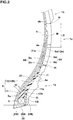
- FIG. 2 is a partial enlarged view of FIG. 1 .
- a tyre middle region 1c which is a region between the tyre inner region 1a and the tyre outer region 1b has a length L5 in the tyre radial direction in a range of from 5% to 25% of the tyre section height H (shown in FIG. 1 ).
- the length L5 of the tyre middle region 1c is less than 5% of the tyre section height H, lengths L1 and L2 of the tyre inner region 1a and the tyre outer region 1b, respectively, become larger, these mass increase, and thus large load may apply to the tyre middle region 1c.
- the length L5 of the tyre middle region 1c exceeds 25% of the tyre section height H, strain occurs on a portion away from the tyre-maximum-width position M, and thus it may be difficult to reduce strain of the bead portions 4. From the above viewpoint, it is more preferable that the length L5 of the tyre middle region 1c is in a range of from 10% to 20% of the tyre section height H.
- the tyre-maximum-width position M is located on a middle region in the tyre radial direction of the tyre middle region 1c.
- the "middle region" in the tyre radial direction of the tyre middle region 1c is a 10% region of the length L5 of the tyre middle region 1c centered at the center location 1i of the tyre middle region 1c in the tyre radial direction.
- the difference of thickness of the tyre middle region 1c between the maximum thickness da and the minimum thickness db is equal to or less than 15% of the maximum thickness da.
- stiffness difference of the tyre middle region 1c tends to be small over the tyre radial direction, uniform flexibility of and around the tyre-maximum-width position M can be ensured.
- the difference between the maximum thickness da and the minimum thickness db is equal to or less than 10%, more preferably equal to or less than 5%, of the maximum thickness da.
- Each bead apex rubber 8 includes a main apex 11 and an outer apex 12.
- the main apex 11, for example, extends outwardly in the tyre radial direction from an outer surface 5a in the tyre radial direction of the bead core 5.
- the outer apex 12, for example, is disposed outwardly in the tyre axial direction of the main apex 11.
- the main apex 11, in the present embodiment, is disposed between the main portions 6a and the turn-up portions 6b of the carcass plies 6A and 6B.
- the outer apex 12, in the present embodiment, is disposed outwardly in the tyre axial direction of the turn-up portions 6b.
- the outer apex 12 can maintain high durability by suppressing the turn-up portions 6b being bent outwardly excessively in the tyre axial direction.
- the carcass plies 6A and 6B extend between the main apex 11 and the outer apex 12 in each bead portion 4.
- the outer end 12e in the tyre radial direction of the outer apex 12, for example, is located outwardly in the tyre radial direction of the outer end 11e in the tyre radial direction of the main apex 11.
- Such an outer apex 12 may exhibit the above-mentioned effect effectively.
- the outer apex 12 has complex elastic modulus E1* in a range of from 15 to 39 MPa.
- complex elastic modulus E2* of the main apex 11 is not limited but is preferably equal to the complex elastic modulus E1* of the outer apex 12.
- complex elastic modulus of rubber is measured based on the Japanese Industrial Standard JIS-K-6394 using a viscoelastic spectrometer manufactured by IWAMOTO SEISAKUSYO under the following conditions:
- the outer apex 12 for example, includes a first portion 12A having a thickness t1 in the tyre axial direction increasing gradually outwardly in the tyre radial direction, and a second portion 12B connected to the first portion 12A and having a thickness t1 in the tyre axial direction decreasing gradually outwardly in the tyre radial direction.
- the first portion 12A in the present embodiment, is in contact with the inner portion 6i of the turn-up portions 6b.
- the second portion 12B in the present embodiment, is in contact with the outer portion 6e of the turn-up portions 6b.
- the outer apex 12 has an inner end 12i in the tyre radial direction which is located outwardly in the tyre radial direction of the outer surface 5a of the bead core 5, for example. Further, the inner end 12i of the outer apex 12, in the present embodiment, is located inwardly in the tyre radial direction of the outer end 11e of the main apex 11. Such an outer apex 12 enables to make the bead portions 4 small in stiffness difference over the tyre radial direction.
- the main apex 11 in the present embodiment, is configured as a triangular cross-sectional shape having a thickness t2 in the tyre axial direction decreasing gradually outwardly in the tyre radial direction from the outer surface 5a of bead core 5.
- the outer end 11e of the main apex 11 is located proximate to the outer end of the inner portion 6i of the turn-up portions 6b in the tyre radial direction.
- FIG. 3 illustrates a partial enlarged view of FIG. 1 .
- the side protector 9 for example, has a protruding height h of from 3 to 7 mm.
- the protruding height h is less than 3 mm, the side protector 9 becomes small in stiffness, and thus it may be difficult to bend the tyre-maximum-width position M sufficiently.
- the protruding height h exceeds 7 mm, the side protector 7 becomes large in rubber volume, and thus the side protector 9 tends to generate heat to excess upon driving, deteriorating durability as well as rolling resistance.
- the "protruding height” is measured perpendicular to the profile line S.
- the side protector 9, in the present embodiment is made of the same rubber as the sidewall rubber 3G. It is preferable that the sidewall rubber 3G had complex elastic modulus E3* of from 3.5 to 9.5 MPa.
- the side protector 9 has an outer end 9e in the tyre radial direction located inwardly in the tyre radial direction of an extended line k in which the belt layer 7 is extended smoothly outwardly in the tyre axial direction while maintain a belt layer profile.
- the inventor has found that a portion around the axial outer ends 7e of the belt layer 7 upon driving generates heat to excess.
- positioning the outer end 9e of the side protector 9 at the above-mentioned location can avoid transmitting heat around the outer ends 7e of the belt layer 7 upon driving to the side protector 9, preventing deterioration of durability as well as rolling resistance.
- the "extended line” is defined by extending the centerline 7c of the innermost belt ply 7A which is disposed innermost in the tyre radial direction smoothly (e.g. while maintaining the profile of the centerline).
- a distance L6 in the tyre radial direction between an intersection k1 of the extended line k to the profile line S and the outer end 9e of the side protector 9, for example, is equal to or more than 2% of the tyre section height H.
- the distance L6 is preferably equal to or less than 10% of the tyre section height H.
- a distance La in the tyre radial direction between at least one of the outer ends 6o of the turn-up portions 6b of the carcass 6 and the bead baseline BL is equal to or more than 50% of the tyre section height H.
- This aspect may offer high stiffness of the tyre middle region 1c, resulting in superior durability.
- the distance La in the tyre radial direction between the outer end 6o of the turn-up portion 6b of the first carcass ply 6A and the bead baseline BL is equal to or more than 50% of the tyre section height H.
- a distance Lb in the tyre radial direction between the outer end 6o of the turn-up portions 6b of the second carcass ply 6B and the bead baseline BL may be equal to or more than 50% of the tyre section height H.
- each sidewall portion 3 the outer ends 6o of the turn-up portions 6b of the first carcass ply 6A and the second carcass ply 6B, respectively, are away from one another in the tyre radial direction, for example. This aspect enables to make the sidewall portion 3 small in stiffness difference, improving durability.
- the tyre-maximum-width position M is located between the outer ends 6o of the first carcass ply 6A and the second carcass ply 6B in the tyre radial direction. This aspect may be useful to bend a portion around the tyre-maximum-width position M further.
- the outer end 6o of the second carcass ply 6B in the present embodiment, is located inwardly in the tyre radial direction of the tyre-maximum-width position M.
- the outer ends 6o of the first and second carcass plies 6A and 6B, in the present embodiment are located in the tyre middle region 1c.
- a distance Lc in the tyre radial direction between the outer ends 6o of the first carcass ply 6A and the second carcass ply 6B is equal to or more than 15 mm, in each sidewall portion 3.
- the tyre middle region 1c varies in stiffness gradually.
- the distance Lc is preferably equal to or less than 25 mm.
- each bead portion 4 includes a chafer rubber 20 for preventing deviation with respect to a rim, and a reinforcing rubber layer 21 for improving stiffness of the bead portion 4.
- the chafer rubber 20 for example, has a thin rubber sheet body having a thickness of from about 0.5 to 1.5 mm.
- the chafer rubber 20, for example, is made of a hard rubber composition with high wear resistance property having complex elastic modulus E*3 of from 4 to 10 MPa.
- the chafer rubber 20 may be configured as a rubber composition only.
- the chafer rubber 20 may be reinforced by a member, e.g., a canvas and/or a cord arrangement body of organic fiber cords.
- the chafer rubber 20, in the present embodiment, includes a main portion 20A, an outer portion 20B, and an inner portion 20C.
- the main portion 20A in the present embodiment, extends in the tyre axial direction so as to be in contact with a rim seat of the rim (not illustrated).
- the outer portion 20B in the present embodiment, is connected to an axially outer end of the main portion 20A and extends outwardly in the tyre radial direction to its terminal end which is sandwiched between the turn-up portions 6b and the outer apex 12.
- the inner portion 20C in the present embodiment, is connected to an axially inner end of the main portion 20A and extends outwardly in the tyre radial direction along the tyre inner surface to its terminal end.
- the outer portion 20B in the present embodiment, is sandwiched between the inner portion 6i of the turn-up portions 6b and the first portion 12A of the outer apex 12.
- the terminal end of the outer portion 20B is located inwardly in the tyre radial direction of the outer end 11e of the main apex 11.
- Such an outer portion 20B can prevent an excessive increase of stiffness of the tyre inner region 1a, and thus strain to be generated upon driving may be concentrated on and around the tyre-maximum-width position M.
- the reinforcing rubber layer 21, in the present embodiment, is connected to the main apex 11 and extends outwardly in the tyre radial direction.
- the reinforcing rubber layer 21, for example, is sandwiched between the main portion 6a and the turn-up portions 6b.
- the reinforcing rubber layer 21 has an outer end 21e in the tyre radial direction located inwardly in the tyre radial direction of the outer end 12e of the outer apex 12.
- the reinforcing rubber layer 21, in the present embodiment, has complex elastic modulus E*4 of from 25 to 85 MPa.
- the reinforcing rubber layer 21, for example, has a thickness t4 in a range of from 0.5 to 3.0 mm.
- Pneumatic tyres having the basic structure shown in FIG. 1 were manufactured by way of trial based on the detail shown in Table 1. Then, durability, cut resistance, appearance, and rolling resistance of each test tyre was tested.
- the common specification and the test method are as follows.
- each test tyre was driven under the following condition: speed of 60 km/hr.; and tyre load of 14.35 kN. Then, runnable distance until damage occurs on either the sidewall portions or the bead portions was measured.
- the test results are shown in Table 1 using an index based on Ref. 1 being 100. The larger value indicates the better performance.
- test tyre set was mounted onto all wheels of a passenger car having a displacement of 2500 cc. Then, a test driver drove the above passenger car on an off-road test course covered with rocks and debris for about 500 km. After driving, damage on the sidewall portions was evaluated based on the number of cuts as well as depths of the cuts. The test results are shown in Table 1 using marks based on Ref. 1 being 100. The larger value indicates the better cut resistance.
- a tester inspected the sidewall portions of each test tyre with naked eyes to evaluate its appearance.
- the test results are shown in Table 1 using marks based on Ref. 1 being 100. The larger the value indicates the better cut resistance.
- rolling resistance of each test tyre was measured under the following condition: speed of 80 km/h; and tyre load of 14.35 kN.
- the test results are shown in Table 1 using an index based on Ref. 1 being 100. The smaller value indicates the smaller rolling resistance.
Claims (12)
- Bandage pneumatique (1) comprenant :une portion formant bande de roulement (2) ;deux portions formant parois latérales axialement distantes (3) s'étendant vers l'intérieur dans une direction radiale du pneumatique depuis la portion formant bande de roulement (2), au moins une des portions formant parois latérales (3) étant dotée d'un protecteur latéral (9) qui se projette vers l'extérieur dans une direction axiale du pneumatique, le protecteur latéral (9) ayant une extrémité intérieure (9i) dans la direction radiale du pneumatique située à l'extérieur dans la direction radiale du pneumatique d'une position de largeur maximum du pneumatique (M) ;deux portions de talon axialement distantes (4) connectées à l'intérieur dans la direction radiale du pneumatique des portions formant parois latérales respectives (3), chaque portion de talon (4) comprenant un caoutchouc de sommet de talon (8), le caoutchouc de sommet de talon (8) ayant une extrémité extérieure (8e) dans la direction radiale du pneumatique qui est située à l'intérieur dans la direction radiale du pneumatique de la position de largeur maximum du pneumatique (M) ; etau moins une nappe de carcasse (6A, 6B) s'étendant entre les portions de talon (4) ;dans lequel les portions de talon (4) comprennent des âmes de talon (5), etdans lequel, dans chaque portion de talon (4), le caoutchouc de sommet de talon (8) comprend un sommet principal (11) qui s'étend vers l'extérieur dans la direction radiale du pneumatique depuis une surface extérieure (5a) dans la direction radiale du pneumatique de l'âme de talon (5), et un sommet extérieur (12) disposé à l'extérieur dans la direction axiale du pneumatique du sommet principal (11),caractérisé en ce queune longueur (L1) dans la direction radiale du pneumatique d'une région intérieure de pneumatique (1a) depuis une ligne de base de talon (BL) jusqu'à l'extrémité extérieure (8e) de chaque caoutchouc de sommet de talon (8) est dans une plage allant de 0,8 à 1,2 fois une longueur (L2) dans la direction radiale du pneumatique d'une région extérieure de pneumatique (1b) depuis une position la plus à l'extérieur (2e) de la portion formant bande de roulement (2) dans la direction radiale du pneumatique jusqu'à l'extrémité intérieure (9i) du protecteur latéral (9), etladite au moins une nappe de carcasse (6A, 6B), dans chaque portion de talon (4), s'étend entre le sommet principal (11) et le sommet extérieur (12).
- Bandage pneumatique (1) selon la revendication 1, dans lequel
une région médiane de pneumatique (1c) qui est une région entre la région intérieure de pneumatique (1a) et la région extérieure de pneumatique (1b) a une longueur (L5) dans la direction radiale du pneumatique dans une plage allant de 5 % à 25 % d'une hauteur de section du pneumatique (H). - Bandage pneumatique (1) selon la revendication 1 ou 2, dans lequel
la position de largeur maximum du pneumatique (M) est située sur une région médiane dans la direction radiale du pneumatique d'une région médiane de pneumatique (1c) qui est une région entre la région intérieure de pneumatique (1a) et la région extérieure de pneumatique (1b). - Bandage pneumatique (1) selon l'une quelconque des revendications 1 à 3, dans lequel
une région médiane de pneumatique (1c) qui est une région entre la région intérieure de pneumatique (1a) et la région extérieure de pneumatique (1b) a une différence d'épaisseur entre une épaisseur maximum (da) de celle-ci et une épaisseur minimum (db) de celle-ci qui est égale ou inférieure à 15 % de l'épaisseur maximum (da). - Bandage pneumatique (1) selon l'une quelconque des revendications 1 à 4, dans lequel
le sommet extérieur (12) a une extrémité extérieure (12e) dans la direction radiale du pneumatique située à l'extérieur dans la direction radiale du pneumatique d'une extrémité extérieure (11e) dans la direction radiale du pneumatique du sommet principal (11). - Bandage pneumatique (1) selon l'une quelconque des revendications 1 à 5, dans lequel
ladite au moins une nappe de carcasse (6A, 6B) comprend une portion principale (6a) s'étendant entre les âmes de talon (5) des portions de talon (4) à travers les portions formant bande de roulement (2) et les portions formant parois latérales (3), et deux portions retroussées axialement distantes (6b) retroussées autour des âmes de talon respectives (5) depuis l'intérieur, axialement, vers l'extérieur du pneumatique (1), et
des longueurs (La) dans la direction radiale du pneumatique entre des extrémités extérieures (6o) dans la direction radiale du pneumatique de la portion retroussée (6b) et la ligne de base de talon (BL) sont égales ou inférieures à 50 % d'une hauteur de section du pneumatique (H). - Bandage pneumatique (1) selon la revendication 6, dans lequel
ladite au moins une nappe de carcasse (6A, 6B) comprend une première nappe de carcasse (6A) et une seconde nappe de carcasse (6B) agencée de manière adjacente sur la première nappe de carcasse (6A), et
dans lequel, dans chaque portion de talon (4), l'extrémité extérieure (6o) de la portion retroussée (6b) de la première nappe de carcasse (6A) est en éloignement de l'extrémité extérieure (6o) de la portion retroussée (6b) de la seconde nappe de carcasse (6B) dans la direction radiale du pneumatique. - Bandage pneumatique (1) selon la revendication 7, dans lequel
dans chaque portion de talon (4), la position de largeur maximum du pneumatique (M) est située entre l'extrémité extérieure (6o) de la première nappe de carcasse (6A) et l'extrémité extérieure (6o) de la seconde nappe de carcasse (6B) dans la direction radiale du pneumatique. - Bandage pneumatique (1) selon la revendication 7 ou 8, dans lequel
dans chaque portion de talon (4), une distance (Lc) dans la direction radiale du pneumatique entre les extrémités extérieures (6o) de la première nappe de carcasse (6A) et de la seconde nappe de carcasse (6B) est égale ou supérieure à 15 mm. - Bandage pneumatique (1) selon l'une quelconque des revendications 1 à 9, dans lequel
dans une condition normale telle que le pneumatique (1) est monté sur une jante de roue standard et est gonflé à une pression standard mais chargé d'aucune charge de pneumatique, la nappe de carcasse (6A, 6B) a un profil de courbure de rayon unique dans une région radiale entre une première position en hauteur (h1) et une seconde position en hauteur (h2), dans lequel
la première position en hauteur (h1) est définie comme étant une position en éloignement de la position de largeur maximum du pneumatique (M) vers l'extérieur dans la direction radiale du pneumatique à une longueur radiale qui est deux fois une longueur radiale (L4) depuis l'extrémité intérieure (9i) du protecteur latéral (9) jusqu'à la position de largeur maximum du pneumatique (M), et
la seconde position en hauteur (h2) est définie comme étant une position en éloignement de la position de largeur maximum du pneumatique (M) vers l'intérieur dans la direction radiale du pneumatique à une longueur radiale qui est deux fois une longueur radiale (L3) depuis l'extrémité extérieure (8e) du caoutchouc de sommet de talon (8) jusqu'à la position de largeur maximum du pneumatique (M). - Bandage pneumatique (1) selon l'une quelconque des revendications 1 à 10, dans lequel
la portion formant bande de roulement (2) comprend une couche de ceinture (7) s'étendant dans la direction axiale du pneumatique, et
dans lequel le protecteur latéral (9) a une extrémité extérieure (9e) dans la direction radiale du pneumatique située dans la direction radiale du pneumatique d'une ligne en extension (k) dans laquelle la couche de ceinture (7) s'étend en douceur vers l'extérieur dans la direction axiale du pneumatique. - Bandage pneumatique (1) selon l'une quelconque des revendications 1 à 11, dans lequel
le protecteur latéral (9) a une hauteur en projection (h) allant de 3 à 7 mm.
Applications Claiming Priority (1)
| Application Number | Priority Date | Filing Date | Title |
|---|---|---|---|
| JP2018234693A JP7192470B2 (ja) | 2018-12-14 | 2018-12-14 | 空気入りタイヤ |
Publications (2)
| Publication Number | Publication Date |
|---|---|
| EP3666556A1 EP3666556A1 (fr) | 2020-06-17 |
| EP3666556B1 true EP3666556B1 (fr) | 2021-04-07 |
Family
ID=68581456
Family Applications (1)
| Application Number | Title | Priority Date | Filing Date |
|---|---|---|---|
| EP19208935.7A Active EP3666556B1 (fr) | 2018-12-14 | 2019-11-13 | Pneumatique |
Country Status (4)
| Country | Link |
|---|---|
| US (1) | US11254167B2 (fr) |
| EP (1) | EP3666556B1 (fr) |
| JP (1) | JP7192470B2 (fr) |
| CN (1) | CN111319403B (fr) |
Families Citing this family (3)
| Publication number | Priority date | Publication date | Assignee | Title |
|---|---|---|---|---|
| JP2023068958A (ja) | 2021-11-04 | 2023-05-18 | 住友ゴム工業株式会社 | 空気入りタイヤ |
| JP2023131633A (ja) | 2022-03-09 | 2023-09-22 | 住友ゴム工業株式会社 | 空気入りタイヤ |
| JP2023151038A (ja) | 2022-03-31 | 2023-10-16 | 住友ゴム工業株式会社 | 空気入りタイヤ |
Family Cites Families (18)
| Publication number | Priority date | Publication date | Assignee | Title |
|---|---|---|---|---|
| US5637162A (en) * | 1991-09-19 | 1997-06-10 | Michelin Recherche Et Technique S.A. | Tire structure for improved tread life |
| JPH0899508A (ja) * | 1994-09-30 | 1996-04-16 | Bridgestone Corp | 空気入りタイヤ |
| US6223797B1 (en) * | 1998-01-29 | 2001-05-01 | The Yokohama Rubber Co. | Pneumatic tire with specified rubber properties |
| JP3337453B2 (ja) | 2000-02-15 | 2002-10-21 | 住友ゴム工業株式会社 | 空気入りタイヤ |
| JP3934623B2 (ja) | 2004-03-29 | 2007-06-20 | 住友ゴム工業株式会社 | 空気入りタイヤ |
| JP4567482B2 (ja) * | 2005-02-14 | 2010-10-20 | 住友ゴム工業株式会社 | 空気入りタイヤ |
| JP4681497B2 (ja) * | 2006-05-08 | 2011-05-11 | 住友ゴム工業株式会社 | 空気入りタイヤ |
| JP5395527B2 (ja) * | 2009-06-12 | 2014-01-22 | 住友ゴム工業株式会社 | 空気入りタイヤ |
| JP2011084144A (ja) | 2009-10-14 | 2011-04-28 | Bridgestone Corp | ランフラットタイヤ |
| BR112012012626A2 (pt) * | 2009-11-25 | 2016-07-12 | Bridgestone Corp | pneu radial enchido com ar para cargas pesadas |
| JP5066240B2 (ja) * | 2010-09-24 | 2012-11-07 | 住友ゴム工業株式会社 | 空気入りタイヤ |
| JP5342580B2 (ja) | 2011-02-28 | 2013-11-13 | 住友ゴム工業株式会社 | 空気入りタイヤ |
| JP5537597B2 (ja) * | 2012-04-23 | 2014-07-02 | 住友ゴム工業株式会社 | 空気入りタイヤ |
| DE112013005717T5 (de) * | 2012-11-30 | 2015-08-20 | The Yokohama Rubber Co., Ltd. | Luftreifen |
| JP6724450B2 (ja) | 2016-03-18 | 2020-07-15 | 住友ゴム工業株式会社 | 空気入りタイヤ |
| JP6786927B2 (ja) * | 2016-07-28 | 2020-11-18 | 住友ゴム工業株式会社 | 空気入りタイヤ |
| JP6848356B2 (ja) * | 2016-11-04 | 2021-03-24 | 住友ゴム工業株式会社 | 空気入りタイヤ |
| JP6946641B2 (ja) * | 2016-12-12 | 2021-10-06 | 住友ゴム工業株式会社 | 空気入りタイヤ |
-
2018
- 2018-12-14 JP JP2018234693A patent/JP7192470B2/ja active Active
-
2019
- 2019-11-01 CN CN201911059195.6A patent/CN111319403B/zh active Active
- 2019-11-13 EP EP19208935.7A patent/EP3666556B1/fr active Active
- 2019-11-22 US US16/692,799 patent/US11254167B2/en active Active
Non-Patent Citations (1)
| Title |
|---|
| None * |
Also Published As
| Publication number | Publication date |
|---|---|
| JP2020093755A (ja) | 2020-06-18 |
| US20200189319A1 (en) | 2020-06-18 |
| EP3666556A1 (fr) | 2020-06-17 |
| US11254167B2 (en) | 2022-02-22 |
| JP7192470B2 (ja) | 2022-12-20 |
| CN111319403A (zh) | 2020-06-23 |
| CN111319403B (zh) | 2023-04-21 |
Similar Documents
| Publication | Publication Date | Title |
|---|---|---|
| EP1440822B1 (fr) | Bandage pneumatique | |
| US7036541B2 (en) | Pneumatic tire | |
| US9108472B2 (en) | Pneumatic heavy-duty tire having circumferential reinforcing layer and sipes | |
| US9150052B2 (en) | Pneumatic tire | |
| EP3424751B1 (fr) | Pneumatique | |
| CN108473004B (zh) | 充气轮胎 | |
| EP3666556B1 (fr) | Pneumatique | |
| US11207927B2 (en) | Pneumatic tire | |
| JP7298622B2 (ja) | 空気入りタイヤ | |
| US11951772B2 (en) | Pneumatic tire | |
| CN109476189B (zh) | 具有减轻重量胎圈区域的轮胎 | |
| JP7388056B2 (ja) | 空気入りタイヤ | |
| JP4687342B2 (ja) | 空気入りタイヤ | |
| JPH11348509A (ja) | 重荷重用空気入りラジアルタイヤ | |
| JP2011235785A (ja) | 空気入りタイヤ | |
| JP7070216B2 (ja) | 空気入りタイヤ | |
| JP7067356B2 (ja) | 空気入りタイヤ | |
| CN108284711B (zh) | 充气轮胎 | |
| JP6852568B2 (ja) | 空気入りタイヤ | |
| EP3838630A1 (fr) | Pneumatique | |
| JP3222682B2 (ja) | 空気入り扁平ラジアルタイヤ | |
| EP3332992B1 (fr) | Pneu pour motocyclettes | |
| EP3613613B1 (fr) | Pneumatique | |
| EP4219193A1 (fr) | Pneumatique et son procédé d'utilisation | |
| JP7187882B2 (ja) | ランフラットタイヤ |
Legal Events
| Date | Code | Title | Description |
|---|---|---|---|
| PUAI | Public reference made under article 153(3) epc to a published international application that has entered the european phase |
Free format text: ORIGINAL CODE: 0009012 |
|
| STAA | Information on the status of an ep patent application or granted ep patent |
Free format text: STATUS: THE APPLICATION HAS BEEN PUBLISHED |
|
| AK | Designated contracting states |
Kind code of ref document: A1 Designated state(s): AL AT BE BG CH CY CZ DE DK EE ES FI FR GB GR HR HU IE IS IT LI LT LU LV MC MK MT NL NO PL PT RO RS SE SI SK SM TR |
|
| AX | Request for extension of the european patent |
Extension state: BA ME |
|
| STAA | Information on the status of an ep patent application or granted ep patent |
Free format text: STATUS: REQUEST FOR EXAMINATION WAS MADE |
|
| 17P | Request for examination filed |
Effective date: 20200723 |
|
| RBV | Designated contracting states (corrected) |
Designated state(s): AL AT BE BG CH CY CZ DE DK EE ES FI FR GB GR HR HU IE IS IT LI LT LU LV MC MK MT NL NO PL PT RO RS SE SI SK SM TR |
|
| RIC1 | Information provided on ipc code assigned before grant |
Ipc: B60C 15/06 20060101ALI20201113BHEP Ipc: B60C 9/02 20060101ALN20201113BHEP Ipc: B60C 15/00 20060101ALN20201113BHEP Ipc: B60C 13/02 20060101AFI20201113BHEP |
|
| GRAP | Despatch of communication of intention to grant a patent |
Free format text: ORIGINAL CODE: EPIDOSNIGR1 |
|
| STAA | Information on the status of an ep patent application or granted ep patent |
Free format text: STATUS: GRANT OF PATENT IS INTENDED |
|
| INTG | Intention to grant announced |
Effective date: 20210113 |
|
| GRAS | Grant fee paid |
Free format text: ORIGINAL CODE: EPIDOSNIGR3 |
|
| GRAA | (expected) grant |
Free format text: ORIGINAL CODE: 0009210 |
|
| STAA | Information on the status of an ep patent application or granted ep patent |
Free format text: STATUS: THE PATENT HAS BEEN GRANTED |
|
| AK | Designated contracting states |
Kind code of ref document: B1 Designated state(s): AL AT BE BG CH CY CZ DE DK EE ES FI FR GB GR HR HU IE IS IT LI LT LU LV MC MK MT NL NO PL PT RO RS SE SI SK SM TR |
|
| REG | Reference to a national code |
Ref country code: GB Ref legal event code: FG4D |
|
| REG | Reference to a national code |
Ref country code: AT Ref legal event code: REF Ref document number: 1379213 Country of ref document: AT Kind code of ref document: T Effective date: 20210415 Ref country code: CH Ref legal event code: EP |
|
| REG | Reference to a national code |
Ref country code: DE Ref legal event code: R096 Ref document number: 602019003775 Country of ref document: DE |
|
| REG | Reference to a national code |
Ref country code: IE Ref legal event code: FG4D |
|
| REG | Reference to a national code |
Ref country code: LT Ref legal event code: MG9D |
|
| REG | Reference to a national code |
Ref country code: NL Ref legal event code: MP Effective date: 20210407 Ref country code: AT Ref legal event code: MK05 Ref document number: 1379213 Country of ref document: AT Kind code of ref document: T Effective date: 20210407 |
|
| PG25 | Lapsed in a contracting state [announced via postgrant information from national office to epo] |
Ref country code: HR Free format text: LAPSE BECAUSE OF FAILURE TO SUBMIT A TRANSLATION OF THE DESCRIPTION OR TO PAY THE FEE WITHIN THE PRESCRIBED TIME-LIMIT Effective date: 20210407 Ref country code: LT Free format text: LAPSE BECAUSE OF FAILURE TO SUBMIT A TRANSLATION OF THE DESCRIPTION OR TO PAY THE FEE WITHIN THE PRESCRIBED TIME-LIMIT Effective date: 20210407 Ref country code: FI Free format text: LAPSE BECAUSE OF FAILURE TO SUBMIT A TRANSLATION OF THE DESCRIPTION OR TO PAY THE FEE WITHIN THE PRESCRIBED TIME-LIMIT Effective date: 20210407 Ref country code: AT Free format text: LAPSE BECAUSE OF FAILURE TO SUBMIT A TRANSLATION OF THE DESCRIPTION OR TO PAY THE FEE WITHIN THE PRESCRIBED TIME-LIMIT Effective date: 20210407 Ref country code: BG Free format text: LAPSE BECAUSE OF FAILURE TO SUBMIT A TRANSLATION OF THE DESCRIPTION OR TO PAY THE FEE WITHIN THE PRESCRIBED TIME-LIMIT Effective date: 20210707 Ref country code: NL Free format text: LAPSE BECAUSE OF FAILURE TO SUBMIT A TRANSLATION OF THE DESCRIPTION OR TO PAY THE FEE WITHIN THE PRESCRIBED TIME-LIMIT Effective date: 20210407 |
|
| PG25 | Lapsed in a contracting state [announced via postgrant information from national office to epo] |
Ref country code: NO Free format text: LAPSE BECAUSE OF FAILURE TO SUBMIT A TRANSLATION OF THE DESCRIPTION OR TO PAY THE FEE WITHIN THE PRESCRIBED TIME-LIMIT Effective date: 20210707 Ref country code: LV Free format text: LAPSE BECAUSE OF FAILURE TO SUBMIT A TRANSLATION OF THE DESCRIPTION OR TO PAY THE FEE WITHIN THE PRESCRIBED TIME-LIMIT Effective date: 20210407 Ref country code: PL Free format text: LAPSE BECAUSE OF FAILURE TO SUBMIT A TRANSLATION OF THE DESCRIPTION OR TO PAY THE FEE WITHIN THE PRESCRIBED TIME-LIMIT Effective date: 20210407 Ref country code: SE Free format text: LAPSE BECAUSE OF FAILURE TO SUBMIT A TRANSLATION OF THE DESCRIPTION OR TO PAY THE FEE WITHIN THE PRESCRIBED TIME-LIMIT Effective date: 20210407 Ref country code: RS Free format text: LAPSE BECAUSE OF FAILURE TO SUBMIT A TRANSLATION OF THE DESCRIPTION OR TO PAY THE FEE WITHIN THE PRESCRIBED TIME-LIMIT Effective date: 20210407 Ref country code: PT Free format text: LAPSE BECAUSE OF FAILURE TO SUBMIT A TRANSLATION OF THE DESCRIPTION OR TO PAY THE FEE WITHIN THE PRESCRIBED TIME-LIMIT Effective date: 20210809 Ref country code: IS Free format text: LAPSE BECAUSE OF FAILURE TO SUBMIT A TRANSLATION OF THE DESCRIPTION OR TO PAY THE FEE WITHIN THE PRESCRIBED TIME-LIMIT Effective date: 20210807 Ref country code: GR Free format text: LAPSE BECAUSE OF FAILURE TO SUBMIT A TRANSLATION OF THE DESCRIPTION OR TO PAY THE FEE WITHIN THE PRESCRIBED TIME-LIMIT Effective date: 20210708 |
|
| REG | Reference to a national code |
Ref country code: DE Ref legal event code: R097 Ref document number: 602019003775 Country of ref document: DE |
|
| PG25 | Lapsed in a contracting state [announced via postgrant information from national office to epo] |
Ref country code: DK Free format text: LAPSE BECAUSE OF FAILURE TO SUBMIT A TRANSLATION OF THE DESCRIPTION OR TO PAY THE FEE WITHIN THE PRESCRIBED TIME-LIMIT Effective date: 20210407 Ref country code: CZ Free format text: LAPSE BECAUSE OF FAILURE TO SUBMIT A TRANSLATION OF THE DESCRIPTION OR TO PAY THE FEE WITHIN THE PRESCRIBED TIME-LIMIT Effective date: 20210407 Ref country code: RO Free format text: LAPSE BECAUSE OF FAILURE TO SUBMIT A TRANSLATION OF THE DESCRIPTION OR TO PAY THE FEE WITHIN THE PRESCRIBED TIME-LIMIT Effective date: 20210407 Ref country code: SM Free format text: LAPSE BECAUSE OF FAILURE TO SUBMIT A TRANSLATION OF THE DESCRIPTION OR TO PAY THE FEE WITHIN THE PRESCRIBED TIME-LIMIT Effective date: 20210407 Ref country code: SK Free format text: LAPSE BECAUSE OF FAILURE TO SUBMIT A TRANSLATION OF THE DESCRIPTION OR TO PAY THE FEE WITHIN THE PRESCRIBED TIME-LIMIT Effective date: 20210407 Ref country code: ES Free format text: LAPSE BECAUSE OF FAILURE TO SUBMIT A TRANSLATION OF THE DESCRIPTION OR TO PAY THE FEE WITHIN THE PRESCRIBED TIME-LIMIT Effective date: 20210407 Ref country code: EE Free format text: LAPSE BECAUSE OF FAILURE TO SUBMIT A TRANSLATION OF THE DESCRIPTION OR TO PAY THE FEE WITHIN THE PRESCRIBED TIME-LIMIT Effective date: 20210407 |
|
| PLBE | No opposition filed within time limit |
Free format text: ORIGINAL CODE: 0009261 |
|
| STAA | Information on the status of an ep patent application or granted ep patent |
Free format text: STATUS: NO OPPOSITION FILED WITHIN TIME LIMIT |
|
| 26N | No opposition filed |
Effective date: 20220110 |
|
| PG25 | Lapsed in a contracting state [announced via postgrant information from national office to epo] |
Ref country code: IS Free format text: LAPSE BECAUSE OF FAILURE TO SUBMIT A TRANSLATION OF THE DESCRIPTION OR TO PAY THE FEE WITHIN THE PRESCRIBED TIME-LIMIT Effective date: 20210807 Ref country code: AL Free format text: LAPSE BECAUSE OF FAILURE TO SUBMIT A TRANSLATION OF THE DESCRIPTION OR TO PAY THE FEE WITHIN THE PRESCRIBED TIME-LIMIT Effective date: 20210407 |
|
| PG25 | Lapsed in a contracting state [announced via postgrant information from national office to epo] |
Ref country code: MC Free format text: LAPSE BECAUSE OF FAILURE TO SUBMIT A TRANSLATION OF THE DESCRIPTION OR TO PAY THE FEE WITHIN THE PRESCRIBED TIME-LIMIT Effective date: 20210407 |
|
| PG25 | Lapsed in a contracting state [announced via postgrant information from national office to epo] |
Ref country code: LU Free format text: LAPSE BECAUSE OF NON-PAYMENT OF DUE FEES Effective date: 20211113 Ref country code: IT Free format text: LAPSE BECAUSE OF FAILURE TO SUBMIT A TRANSLATION OF THE DESCRIPTION OR TO PAY THE FEE WITHIN THE PRESCRIBED TIME-LIMIT Effective date: 20210407 Ref country code: BE Free format text: LAPSE BECAUSE OF NON-PAYMENT OF DUE FEES Effective date: 20211130 |
|
| REG | Reference to a national code |
Ref country code: BE Ref legal event code: MM Effective date: 20211130 |
|
| PG25 | Lapsed in a contracting state [announced via postgrant information from national office to epo] |
Ref country code: IE Free format text: LAPSE BECAUSE OF NON-PAYMENT OF DUE FEES Effective date: 20211113 |
|
| P01 | Opt-out of the competence of the unified patent court (upc) registered |
Effective date: 20230510 |
|
| PG25 | Lapsed in a contracting state [announced via postgrant information from national office to epo] |
Ref country code: CY Free format text: LAPSE BECAUSE OF FAILURE TO SUBMIT A TRANSLATION OF THE DESCRIPTION OR TO PAY THE FEE WITHIN THE PRESCRIBED TIME-LIMIT Effective date: 20210407 |
|
| REG | Reference to a national code |
Ref country code: CH Ref legal event code: PL |
|
| PG25 | Lapsed in a contracting state [announced via postgrant information from national office to epo] |
Ref country code: LI Free format text: LAPSE BECAUSE OF NON-PAYMENT OF DUE FEES Effective date: 20221130 Ref country code: HU Free format text: LAPSE BECAUSE OF FAILURE TO SUBMIT A TRANSLATION OF THE DESCRIPTION OR TO PAY THE FEE WITHIN THE PRESCRIBED TIME-LIMIT; INVALID AB INITIO Effective date: 20191113 Ref country code: CH Free format text: LAPSE BECAUSE OF NON-PAYMENT OF DUE FEES Effective date: 20221130 |
|
| PGFP | Annual fee paid to national office [announced via postgrant information from national office to epo] |
Ref country code: FR Payment date: 20230929 Year of fee payment: 5 |
|
| PGFP | Annual fee paid to national office [announced via postgrant information from national office to epo] |
Ref country code: DE Payment date: 20230929 Year of fee payment: 5 |
|
| PG25 | Lapsed in a contracting state [announced via postgrant information from national office to epo] |
Ref country code: MK Free format text: LAPSE BECAUSE OF FAILURE TO SUBMIT A TRANSLATION OF THE DESCRIPTION OR TO PAY THE FEE WITHIN THE PRESCRIBED TIME-LIMIT Effective date: 20210407 |