EP3662240B1 - Élément de machine muni d'un dispositif de détection et procédé de fabrication d'un élément de machine - Google Patents
Élément de machine muni d'un dispositif de détection et procédé de fabrication d'un élément de machine Download PDFInfo
- Publication number
- EP3662240B1 EP3662240B1 EP16739014.5A EP16739014A EP3662240B1 EP 3662240 B1 EP3662240 B1 EP 3662240B1 EP 16739014 A EP16739014 A EP 16739014A EP 3662240 B1 EP3662240 B1 EP 3662240B1
- Authority
- EP
- European Patent Office
- Prior art keywords
- sensor device
- radially inwardly
- machine element
- formation
- inwardly projecting
- Prior art date
- Legal status (The legal status is an assumption and is not a legal conclusion. Google has not performed a legal analysis and makes no representation as to the accuracy of the status listed.)
- Active
Links
- 238000004519 manufacturing process Methods 0.000 title claims description 15
- 230000015572 biosynthetic process Effects 0.000 claims description 85
- 238000005755 formation reaction Methods 0.000 claims description 85
- 230000002093 peripheral effect Effects 0.000 claims description 14
- 238000007493 shaping process Methods 0.000 claims description 11
- 238000000034 method Methods 0.000 claims description 10
- 230000005540 biological transmission Effects 0.000 description 6
- 239000000463 material Substances 0.000 description 6
- 238000005259 measurement Methods 0.000 description 5
- 238000011156 evaluation Methods 0.000 description 4
- 238000010273 cold forging Methods 0.000 description 3
- 238000001514 detection method Methods 0.000 description 3
- 238000012544 monitoring process Methods 0.000 description 3
- 239000010453 quartz Substances 0.000 description 3
- VYPSYNLAJGMNEJ-UHFFFAOYSA-N silicon dioxide Inorganic materials O=[Si]=O VYPSYNLAJGMNEJ-UHFFFAOYSA-N 0.000 description 3
- 238000005520 cutting process Methods 0.000 description 2
- 230000006735 deficit Effects 0.000 description 2
- 238000013461 design Methods 0.000 description 2
- 238000011161 development Methods 0.000 description 2
- 238000003754 machining Methods 0.000 description 2
- 230000036316 preload Effects 0.000 description 2
- 239000007787 solid Substances 0.000 description 2
- 238000004026 adhesive bonding Methods 0.000 description 1
- 239000011324 bead Substances 0.000 description 1
- 239000011248 coating agent Substances 0.000 description 1
- 238000000576 coating method Methods 0.000 description 1
- 239000013078 crystal Substances 0.000 description 1
- 230000001419 dependent effect Effects 0.000 description 1
- 238000006073 displacement reaction Methods 0.000 description 1
- 230000000694 effects Effects 0.000 description 1
- 238000005516 engineering process Methods 0.000 description 1
- 230000007613 environmental effect Effects 0.000 description 1
- 239000011796 hollow space material Substances 0.000 description 1
- 238000003780 insertion Methods 0.000 description 1
- 230000037431 insertion Effects 0.000 description 1
- 230000010354 integration Effects 0.000 description 1
- 238000004898 kneading Methods 0.000 description 1
- 239000002184 metal Substances 0.000 description 1
- 230000000717 retained effect Effects 0.000 description 1
- 238000010099 solid forming Methods 0.000 description 1
- 238000012360 testing method Methods 0.000 description 1
- 238000005303 weighing Methods 0.000 description 1
Images


Classifications
-
- G—PHYSICS
- G01—MEASURING; TESTING
- G01L—MEASURING FORCE, STRESS, TORQUE, WORK, MECHANICAL POWER, MECHANICAL EFFICIENCY, OR FLUID PRESSURE
- G01L5/00—Apparatus for, or methods of, measuring force, work, mechanical power, or torque, specially adapted for specific purposes
- G01L5/0004—Force transducers adapted for mounting in a bore of the force receiving structure
-
- G—PHYSICS
- G01—MEASURING; TESTING
- G01L—MEASURING FORCE, STRESS, TORQUE, WORK, MECHANICAL POWER, MECHANICAL EFFICIENCY, OR FLUID PRESSURE
- G01L1/00—Measuring force or stress, in general
- G01L1/16—Measuring force or stress, in general using properties of piezoelectric devices
-
- G—PHYSICS
- G01—MEASURING; TESTING
- G01L—MEASURING FORCE, STRESS, TORQUE, WORK, MECHANICAL POWER, MECHANICAL EFFICIENCY, OR FLUID PRESSURE
- G01L1/00—Measuring force or stress, in general
- G01L1/20—Measuring force or stress, in general by measuring variations in ohmic resistance of solid materials or of electrically-conductive fluids; by making use of electrokinetic cells, i.e. liquid-containing cells wherein an electrical potential is produced or varied upon the application of stress
- G01L1/22—Measuring force or stress, in general by measuring variations in ohmic resistance of solid materials or of electrically-conductive fluids; by making use of electrokinetic cells, i.e. liquid-containing cells wherein an electrical potential is produced or varied upon the application of stress using resistance strain gauges
- G01L1/2206—Special supports with preselected places to mount the resistance strain gauges; Mounting of supports
- G01L1/2218—Special supports with preselected places to mount the resistance strain gauges; Mounting of supports the supports being of the column type, e.g. cylindric, adapted for measuring a force along a single direction
- G01L1/2225—Special supports with preselected places to mount the resistance strain gauges; Mounting of supports the supports being of the column type, e.g. cylindric, adapted for measuring a force along a single direction the direction being perpendicular to the central axis
-
- G—PHYSICS
- G01—MEASURING; TESTING
- G01L—MEASURING FORCE, STRESS, TORQUE, WORK, MECHANICAL POWER, MECHANICAL EFFICIENCY, OR FLUID PRESSURE
- G01L1/00—Measuring force or stress, in general
- G01L1/20—Measuring force or stress, in general by measuring variations in ohmic resistance of solid materials or of electrically-conductive fluids; by making use of electrokinetic cells, i.e. liquid-containing cells wherein an electrical potential is produced or varied upon the application of stress
- G01L1/22—Measuring force or stress, in general by measuring variations in ohmic resistance of solid materials or of electrically-conductive fluids; by making use of electrokinetic cells, i.e. liquid-containing cells wherein an electrical potential is produced or varied upon the application of stress using resistance strain gauges
- G01L1/2287—Measuring force or stress, in general by measuring variations in ohmic resistance of solid materials or of electrically-conductive fluids; by making use of electrokinetic cells, i.e. liquid-containing cells wherein an electrical potential is produced or varied upon the application of stress using resistance strain gauges constructional details of the strain gauges
-
- G—PHYSICS
- G01—MEASURING; TESTING
- G01L—MEASURING FORCE, STRESS, TORQUE, WORK, MECHANICAL POWER, MECHANICAL EFFICIENCY, OR FLUID PRESSURE
- G01L5/00—Apparatus for, or methods of, measuring force, work, mechanical power, or torque, specially adapted for specific purposes
- G01L5/16—Apparatus for, or methods of, measuring force, work, mechanical power, or torque, specially adapted for specific purposes for measuring several components of force
- G01L5/167—Apparatus for, or methods of, measuring force, work, mechanical power, or torque, specially adapted for specific purposes for measuring several components of force using piezoelectric means
-
- G—PHYSICS
- G01—MEASURING; TESTING
- G01L—MEASURING FORCE, STRESS, TORQUE, WORK, MECHANICAL POWER, MECHANICAL EFFICIENCY, OR FLUID PRESSURE
- G01L5/00—Apparatus for, or methods of, measuring force, work, mechanical power, or torque, specially adapted for specific purposes
- G01L5/16—Apparatus for, or methods of, measuring force, work, mechanical power, or torque, specially adapted for specific purposes for measuring several components of force
- G01L5/168—Apparatus for, or methods of, measuring force, work, mechanical power, or torque, specially adapted for specific purposes for measuring several components of force using counterbalancing forces
Definitions
- the invention relates to a machine element with a hollow shaft section and with a sensor device for detecting a mechanical stress affecting the hollow shaft section, the sensor device being arranged in the hollow shaft section, the hollow shaft section having a first radially inwardly protruding formation and a second radially inwardly protruding formation having, and wherein the sensor device is positively fixed with an axial preload between the first radially inwardly projecting formation and the second radially inwardly projecting formation.
- Tubular or rod-shaped machine elements are used as shafts or hollow shafts, as axles or as rod structures in many areas of mechanical and plant engineering.
- suitable sensors are fixed externally to a surface of the machine element, particularly in test benches and development trials, and the sensor values are recorded and evaluated.
- strain gauges can be used, with which even minor deformations on the surface of the machine element can be measured cost-effectively and reliably.
- a continuous acquisition of sensor values is advantageous and sometimes necessary, for example, in weighing technology, in load monitoring and in production monitoring and production control.
- sensor devices and possible uses are also known with which structural damage such as cracks or plastic deformations can be detected at an early stage, which can possibly lead to an impairment of the function of the machine element or to damage and reduce the service life and reliability of the machine element.
- structural damage such as cracks or plastic deformations
- an impending failure of the machine element can be detected before a critical state occurs.
- the sensor device In order to enable the most reliable and precise detection possible of the mechanical stresses affecting the machine element, the sensor device must be fixed to the machine element as precisely and permanently as possible. At the same time should avoid that the sensor device is exposed to excessive stress during the measurement period, during the intended use and also during manufacture and assembly, which could lead to incorrect measurements or damage to the sensor device. At the same time, compared to a conventional machine element, there should be no restrictions due to the sensors and handling and use, such as those caused by sensors applied to an outside of the machine element or by joints that may be required for the attachment of sensors.
- the sensor device is arranged to protect against external influences and environmental conditions in a cavity of a shaft.
- the sensor device is protected in the hollow space of the shaft against operational mechanical and schematic influences and against any willful damage.
- vibrations and structure-borne noise of the machine element can be recorded and evaluated.
- a permanently precise fixing of the sensor device in the cavity is not necessary since no deformation of the cavity of the machine element is to be detected by the sensor device in the embodiment in question.
- Hollow shafts are known in which a sensor device is adhesively fixed in an interior space of the hollow shaft or is pressed in with a non-positive fit.
- sensor devices arranged in this way are only suitable to a limited extent for the comprehensive detection of axial and radial deformations of the hollow shaft, since reliable evaluation of the sensor signals usually requires that the sensor in question or the sensor device be fixed with a prestress at the measuring point.
- assembly work involved in arranging and fixing the sensor device for example, in the pamphlet US2015/030408 discloses a device and a method, wherein the sensor device arranged in a hollow shaft can be fixed in an axial direction in the hollow shaft.
- the sensor device is introduced into a cylindrical cavity which has a constant diameter in the hollow shaft.
- the sensor unit is then fixed in the hollow shaft in the axial direction by forces acting radially on the hollow shaft.
- a non-rotatable fixing of the sensor device as a result of which torsional forces acting on the hollow shaft can also be transmitted to the sensor unit with little loss, is not discussed here.
- a stop surface of the first radially inwardly projecting formation and/or a stop surface of the second radially inwardly projecting formation has a circumferentially profiled surface which forms an engagement with the sensor device.
- the two radially inwardly projecting formations can be, for example, peripheral beads in a cylindrical surface delimiting an interior space of the hollow shaft section.
- the radially inwardly projecting formations each have a smaller inside diameter than the areas of the hollow shaft section that adjoin in the axial direction on both sides of the respective formation.
- the radially inwardly projecting formation may have a triangular cross-sectional area with tapering or conically tapering side surfaces. It is also possible for the radially inwardly projecting formation to have an asymmetrical cross-sectional shape.
- the inwardly protruding formations can each form one or more stop surfaces on which each other opposite end faces of the sensor device can abut.
- the sensor device is fixed in a form-fitting manner between the two radially inwardly projecting formations, so that an undesired axial displacement of the sensor device can be ruled out.
- a contact pressure can be exerted on the sensor device located between them, thereby forcing an axial pretension of the sensor device.
- the axial prestressing can be predetermined to be sufficiently large, so that the sensor device is fixed in a frictionally sufficiently non-rotatable manner relative to the surrounding hollow shaft section in order to also be able to reliably detect acting torques and torsional loads.
- the axial preload is expediently specified to be sufficiently large in order to counteract gradual creep effects that could otherwise occur at the temperatures and mechanical loads that usually occur during the intended use.
- the prestressing of the sensor device can, with suitably selected and attached sensors, enable a measurement signal that is linearly dependent on the deformation to be measured over wide ranges and facilitates precise evaluation.
- the surface profiled in the circumferential direction can be, for example, wavy or tooth-shaped have structuring. It is also conceivable that the surface has grooves or ridges running in the axial direction. The surface can also be roughened or provided with a sufficiently uneven or rough coating.
- the sensor device is fixed in a rotationally fixed manner in the hollow shaft section, so that even large torques can be reliably detected.
- the sensor device has a first end face and/or a second end face with a peripheral edge area and with a chamfer formed in the edge area.
- the first radially inwardly protruding formation and/or the second radially inwardly protruding formation have a stop surface inclined at an angle to a central axis of the hollow shaft section.
- the abutment surface can, for example, have an angle or an inclination of the abutment surface of between 20 and 30 degrees.
- the radially inward projections can be with produce a stop surface inclined at an angle easily and inexpensively.
- the desired prestressing of the sensor device can be maintained over a long period of time with low error tolerances by means of an inclined stop surface.
- the first radially inwardly projecting formation and/or the second radially inwardly projecting formation to have a constant cross-sectional area in the circumferential direction.
- the risk of an undesired imbalance during the intended rotation of the machine element can be reduced with a constant or rotationally symmetrical shape of the protrusions.
- the constant cross-sectional area of the inwardly protruding formations in the circumferential direction favors alignment of the sensor device along a central axis and significantly reduces the risk of undesired transverse force components that could act on the sensor device in the radial direction.
- the sensor device has a first end face and/or a second end face with a peripheral edge region with a shape that is profiled in the peripheral direction and which, with the first one, radially downwards inwardly projecting formation or the second radially inwardly projecting formation forms an engagement.
- the circumferentially profiled shape in the edge area of the end faces of the sensor device is expediently adapted to the surface profile of the stop faces of the inwardly projecting formations. In this way, the sensor device can be fastened in the hollow shaft section in a reliable and extremely non-rotatable manner with little effort.
- the shape, which is profiled in the circumferential direction, can advantageously be combined with a likewise circumferential chamfer.
- Such a form-fitting engagement in the circumferential direction can ensure that the sensor device is secured against rotation in the hollow shaft section and torques and deformations caused by torsion can be detected reliably and precisely with the sensor device.
- Undesirable twisting of the sensor device relative to the surrounding hollow shaft section only occurs when the external forces and moments force plastic deformation of the positive engagement between the sensor device and the adjacent radially inwardly projecting formations or destroy the positive engagement.
- the sensor device prefferably has a shape of the circumferential edge region of a first end face and/or second end face of the sensor device that is adapted to a shape of the first or second radially inwardly projecting formation. In this way, the largest possible contact surface can be made possible and it can be achieved that the sensor device rests over a large area on corresponding stop surfaces of these formations even with formations that protrude only slightly inwards.
- the sensor device has at least one deformation sensor.
- Suitable preforming sensors are, for example, strain gauge arrangements or piezo sensors or quartz disc sensors, with which very precise measurements of deformations of the hollow shaft section, which are generated by an acting mechanical stress, are possible at low cost. Due to the prestressing of the sensor device generated in the axial direction, the deformation sensors used can be operated with a corresponding prestressing and thus not only torques but also tensile and compressive forces acting in the axial direction can be reliably detected. In addition, numerous deformation sensors, which can be fixed under prestress at the respective measurement location, show a linear and thus permanently precisely analyzable dependency of the sensor signals generated on the causing deformation over a wide measuring range.
- An arrangement of several piezoelectric elementary sensors connected in series allows several differently directed components of acting forces and moments to be recorded and also offers the advantage that there is no need for time-consuming gluing of other elementary sensors, such as strain gauges .
- the machine element can be a shaft.
- the hollow shaft section can also extend essentially over the entire shaft in the axial direction, so that the machine element is a hollow shaft. It is also possible for the hollow shaft section to only have a short extent in the axial direction, which is adapted to the dimensions of the sensor device to be accommodated therein, so that only the smallest possible mechanical influence on a solid shaft or a solid machine element occurs.
- the machine element can also be an axis or a rod-shaped component of a rod structure in a machine or plant.
- the invention also relates to a method for producing a machine element with a hollow shaft section and with a sensor device arranged therein for measuring a mechanical stress affecting the hollow shaft section, the sensor device having an axial prestress between a first radially inwardly projecting formation and a second radially backward inside protruding formation is fixed positively.
- a first radially inwardly projecting shape is produced in the hollow shaft section of the machine element.
- a sensor device is placed in a form-fitting manner in the hollow shaft section on the first radially inwardly projecting formation.
- a second radial inwardly projecting formation is produced in the hollow shaft section, a mandrel introduced into the hollow shaft section being used to define a circumferentially profiled shaping of the first and/or second radially inwardly projecting formation.
- a forming process to reduce a diameter of the hollow shaft section can be carried out.
- the arrangement and fixing of the sensor device is therefore integrated according to the invention into the manufacturing process of the machine element, which is possible with little additional effort.
- the mandrel has a profiling in its end area, which represents a negative form of the desired profiling of the inwardly projecting formations.
- a cold forging of the machine element some material of the blank or the machine element flows into the through the end area of the Dorn's predetermined negative shape, whereby a corresponding profiling of the radially inwardly projecting formations is generated.
- the specified surface profile remains.
- the machine element can be produced particularly inexpensively and easily in that the first formation projecting radially inward and the second formation projecting radially inward are produced by cold forging.
- the machine element consists of a material in the area of the radially inwardly projecting formations that is suitable for cold solid forming. Since the machine element can or should be made of metal for numerous purposes and areas of use, the manufacturing method according to the invention can be used advantageously in combination with cold forging for such machine elements.
- the formations projecting radially inwards are produced by rotary swaging.
- At least the hollow shaft section and possibly the entire machine element are expediently converted into the desired shape by rotary swaging, starting from a blank.
- a prefabricated blank shape is expedient, which has outer and inner contours adapted to the manufacturing process.
- an in mandrel inserted into the cavity can be used, which has a suitable design and shape of an end region and, depending on its positioning within the hollow shaft section, influences or predetermines the shaping of a radially inwardly projecting shape forced by rotary kneading.
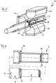
- a tubular blank 3 can be used for production, as is shown in 1 is shown. Inserted into the tubular blank 3 is a mandrel 4 having a first section 5 with a slightly smaller radius and a second section 6 with a slightly larger radius.
- the respective end regions of the two sections 5 and 6 each have one in the circumferential direction profiled chamfer 7 and 8.
- the length of the first section 5 and the distance between the two bevels 7 and 8 correspond approximately to the length of the sensor device 2 in the axial direction, with the sensor device 2 expediently being somewhat longer.
- the inwardly flowing material of the blank 3 in this area flows to the circumferentially profiled bevel 7 of the mandrel 3, which acts as a negative mold and creates a corresponding profiling of an inclined contact surface 13 of the inwardly projecting formation 12.
- the angle of inclination ⁇ of the contact surface 13 relative to the central axis 11 is approximately 21°.
- a conically tapering area 14 of the blank 3 in the area of the bevel 8 of the mandrel 4 is produced by machining the blank 3 with the machine tool 9 .
- This area 14 also has a profile in the circumferential direction that is adapted to the profile of the bevel 8 or is predetermined by it.
- the mandrel 4 is then pulled out and the sensor device 2 is inserted into the blank 3 until a first end face 15 of the sensor device 2 rests against the inwardly projecting formation 12 .
- a second mandrel 16 is then inserted into the blank 3 and pressed against a second end face 17 of the sensor device 2, so that the sensor device 2 is under axial prestress.
- the second mandrel 16 has a diameter that corresponds to the diameter of the first section 5 of the mandrel 4 .
- the mandrel 16 also has a chamfer 19, as shown in 3 is shown.
- the first mandrel 4 could also be reinserted and pressed against the second end face 17 of the sensor device 2.
- the blank 3 with the sensor device 2 arranged therein is shifted together with the mandrel 16 relative to the machine tool 9, while the oscillating rotary swaging tools 10 are used to convert the blank 3 into the final shape of the hollow shaft 1 via the initially conically tapering area 14 .
- a second inwardly protruding formation 20 is formed, the shape of which is predetermined by the second end face 17 of the sensor device 2 and the chamfer 19 of the mandrel 16 .
- a contact surface 21 of the formation 20 facing the sensor device 2 essentially retains the profiling of the conically tapering region 14 , which is converted into the second formation 20 protruding inwards.
- the sensor device 2 is under the predetermined by the mandrel 16 bias in the axial direction form-fitting between the first after inwardly protruding formation 12 and the newly formed second inwardly protruding formation 20, wherein a snuggling of the conically tapering area 14 to the second end face 17 leads to an additional axially directed force component or prestressing in the sensor device 2.
- the finished hollow shaft 1 with the sensor device 2 fixed therein is in 4 pictured.
- the sensor device 2 is pressed together and compressed in the axial direction, so that the prestress is generated or maintained during the forming process that reduces the diameter.
- the angle of inclination ⁇ of the first radially inwardly projecting formation 12 can also be specified differently, since the contact surface 13 can be designed exclusively with the aim of a reliable form fit.
- the angle of inclination ⁇ on the contact surface 21 of the second inwardly projecting formation 20 is also important with regard to the desired material flow during the forming process and for the generation of a transverse force acting in the axial direction during the radially acting rotary swaging process and should therefore expediently be in a range be between 20° and 30°.
- the previously generated profiling in the circumferential direction of the tapering area 14 and a corresponding profiling of the first inwardly projecting formation 12 simultaneously creates a form-fitting engagement in the circumferential direction and the sensor device 2 is rotationally fixed between the two inwards projecting formations 12 and 20 set in an interior of the hollow shaft 1.
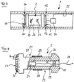
- the sensor device 2 has a suitable sensor carrier 22 on which a plurality of deformation sensors 23 are fixed.
- the sensor values measured with the deformation sensors 23 can, for example, be transmitted wirelessly to an evaluation device.
- FIG 7 shows an example of the sensor device 2 fixed in the hollow shaft 1 between the two radially inwardly projecting formations 12 and 20 together with an amplifier and transmission device 24 and an antenna 25 for wireless transmission of the sensor values to an external evaluation device (not shown).
- the amplifier and transmission device 24 is arranged directly adjacent to the sensor device 2 in the hollow shaft 1 and is electrically conductively connected to the deformation sensors 23 on the sensor carrier 22 through the end face 15 .
- the Amplifier and transmission device 24 in a cavity 26 inside the sensor carrier 22.
- the deformation sensors 23 glued to an outer peripheral surface 28 in a radially recessed belt area 27 of the sensor carrier 22 are electrically conductively connected to the amplifier and transmission device 24.
- the antenna 25 is guided out of the sensor carrier 22 in the axial direction through a seal 29 .
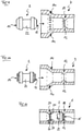
- the sensor device 2 has a number of tooth-shaped or nose-shaped ones on both end faces 15 and 17 Formations 30 on.
- the profiling of the contact surfaces 13 and 21 and the formation of tooth-shaped or nose-shaped formations 30 in the area of the end faces 15 and 17 of the sensor device 2 can be produced in various ways.
- suitable profiling of the bevels 7 and 8 of the mandrel 4 arranged inside the blank 3 predetermines a profiling of the contact surface 13 and the tapering area 14 that is adapted thereto or forced by it.
- the two end faces 15 and 17 of the subsequently introduced sensor device 2 are made of a less hard material than the blank 3, so that its profiling can occur when the sensor device 2 is pressed in axially and the tapering area 14 is retained and a profiling of the end faces 15 and 17 of the sensor device 2 adapted thereto is enforced.
- the profiling on the end faces 15 and 17 of the sensor device 2 is specified and transferred to the contact surfaces 13 and 21 of the radially inwardly projecting formations 12 and 20.
- an in 11 causes a form fit shown schematically, which exists in the circumferential direction between the end faces 15 and 17 and the respective associated contact surfaces 13 and 21 and undesired twisting of the sensor device 2 relative to the surrounding hollow shaft 1 prevents.
- a portion of the sensor device 2 is shown in the figure on the right.
- the profiling specified in the circumferential direction is located both on the end face 15 of the sensor device 2 shown on the right and in the contact surface 21 shown on the left of the radially inwardly projecting formation 20, so that a form-fitting engagement between the sensor device 2 and the hollow shaft emanating from both surfaces 1 is specified.
- the sensor device 2 is arranged in a blind hole 31 in a shaft 32 .
- the sensor device 2 has several piezoelectric quartz discs 33 with different Cutting direction planes, which are connected in series in the axial direction one behind the other.
Landscapes
- Physics & Mathematics (AREA)
- General Physics & Mathematics (AREA)
- Force Measurement Appropriate To Specific Purposes (AREA)
- Forging (AREA)
Claims (13)
- Élément de machine (1, 32) comprenant une partie d'arbre creux et un dispositif de détection (2) pour détecter une contrainte mécanique agissant sur la partie d'arbre creux, le dispositif de détection (2) étant disposé dans la partie d'arbre creux, la partie d'arbre creux présentant une première protubérance (12) faisant saillie radialement vers l'intérieur et une seconde protubérance (20) faisant saillie radialement vers l'intérieur, et le dispositif de détection (2) étant immobilisé par complémentarité de forme, avec une précontrainte axiale, entre la première protubérance (12) faisant saillie radialement vers l'intérieur et la seconde protubérance (20) faisant saillie radialement vers l'intérieur, caractérisé en ce qu'une surface de butée (13) de la première protubérance (12) faisant saillie radialement vers l'intérieur et/ou une surface de butée (21) de la seconde protubérance (20) faisant saillie radialement vers l'intérieur présente une surface profilée dans la direction circonférentielle, qui forme un engrènement avec le dispositif de détection (2).
- Élément de machine (1, 32) selon la revendication 1, caractérisé en ce que la première protubérance (12) faisant saillie radialement vers l'intérieur et/ou la seconde protubérance (20) faisant saillie radialement vers l'intérieur présente une surface de butée (13, 21) inclinée selon un angle par rapport à un axe central (11) de la partie d'arbre creux.
- Élément de machine (1, 32) selon la revendication 1 ou la revendication 2, caractérisé en ce que la première protubérance (12) faisant saillie radialement vers l'intérieur et/ou la seconde protubérance (20) faisant saillie radialement vers l'intérieur présentent une aire de section transversale constante dans la direction circonférentielle.
- Élément de machine (1, 32) selon l'une des revendications 1 à 3, caractérisé en ce que le dispositif de détection (2) présente une première face frontale (15) et/ou une seconde face frontale (17) avec une zone de bord périphérique et avec un chanfrein réalisé dans la zone de bord.
- Élément de machine (1, 32) selon l'une des revendications précédentes, caractérisé en ce que le dispositif de détection (2) présente une première face frontale (15) et/ou une seconde face frontale (17) avec une zone de bord périphérique avec une forme profilée dans la direction circonférentielle, qui forme un engrènement avec respectivement la première protubérance (12) faisant saillie radialement vers l'intérieur et la seconde protubérance (20) faisant saillie radialement vers l'intérieur.
- Élément de machine (1, 32) selon la revendication 5, caractérisé en ce que la zone de bord périphérique de la première face frontale (15) et/ou de la seconde face frontale (17) forme, avec la forme profilée dans la direction circonférentielle, une surface de contact inclinée selon un angle par rapport à l'axe central (11) et la précontrainte axiale du dispositif de détection (2) est prédéfinie par la surface de contact inclinée.
- Élément de machine (1, 32) selon l'une des revendications précédentes, caractérisé en ce que le dispositif de détection (2) présente une forme d'une première face frontale (15) et/ou d'une seconde face frontale (17) du dispositif de détection (2) adaptée à une forme respectivement de la première et de la seconde protubérance (12, 20) faisant saillie radialement vers l'intérieur.
- Élément de machine (1, 32) selon l'une des revendications précédentes, caractérisé en ce que le dispositif de détection (2) présente au moins un capteur de déformation (23) .
- Élément de machine (1, 32) selon l'une des revendications précédentes, caractérisé en ce que l'élément de machine est un arbre (32) ou un arbre creux (1).
- Procédé de fabrication d'un élément de machine (1, 32) comprenant une partie d'arbre creux et un dispositif de détection (2) disposé dans celle-ci pour mesurer une contrainte mécanique agissant sur la partie d'arbre creux, dans lequel le dispositif de détection (2) est immobilisé par complémentarité de forme, avec une précontrainte axiale, entre une première protubérance (12) faisant saillie radialement vers l'intérieur et une seconde protubérance (20) faisant saillie radialement vers l'intérieur, caractérisé en ce que, dans une première étape de façonnage, une première protubérance (12) faisant saillie radialement vers l'intérieur est générée dans la partie d'arbre creux de l'élément de machine (1, 32), dans lequel, dans une étape suivante de disposition de capteur, un dispositif de détection (2) est appliqué par complémentarité de forme dans la partie d'arbre creux contre la première protubérance (12) faisant saillie vers l'intérieur, et dans lequel, dans une étape suivante d'immobilisation, une seconde protubérance (20) faisant saillie radialement vers l'intérieur est générée dans la partie d'arbre creux, dans lequel une forme profilée dans la direction circonférentielle de la première et/ou seconde protubérance (12, 20) faisant saillie radialement vers l'intérieur est prédéfinie avec un mandrin (4) introduit dans la partie d'arbre creux.
- Procédé selon la la revendication 10, caractérisé en ce que la première protubérance (12) faisant saillie radialement vers l'intérieur et la seconde protubérance (20) faisant saillie radialement vers l'intérieur sont générées par matriçage à froid.
- Procédé selon la revendication 11, caractérisé en ce que les protubérances (12, 20) faisant saillie radialement vers l'intérieur sont générées par rétreint.
- Procédé selon l'une des revendications 10 à 12, caractérisé en ce qu'une forme profilée dans la direction circonférentielle de la première et/ou seconde protubérance (12, 20) faisant saillie radialement vers l'intérieur est prédéfinie par les faces frontales (15, 17) profilées du dispositif de détection (2).
Applications Claiming Priority (2)
| Application Number | Priority Date | Filing Date | Title |
|---|---|---|---|
| DE102015106933.4A DE102015106933A1 (de) | 2015-05-04 | 2015-05-04 | Maschinenelement mit einer Sensoreinrichtung und Verfahren zur Herstellung eines Maschinenelements |
| PCT/DE2016/000184 WO2016177356A1 (fr) | 2015-05-04 | 2016-05-03 | Élément de machine muni d'un dispositif de détection et procédé de fabrication d'un élément de machine |
Publications (2)
| Publication Number | Publication Date |
|---|---|
| EP3662240A1 EP3662240A1 (fr) | 2020-06-10 |
| EP3662240B1 true EP3662240B1 (fr) | 2022-03-09 |
Family
ID=56413447
Family Applications (1)
| Application Number | Title | Priority Date | Filing Date |
|---|---|---|---|
| EP16739014.5A Active EP3662240B1 (fr) | 2015-05-04 | 2016-05-03 | Élément de machine muni d'un dispositif de détection et procédé de fabrication d'un élément de machine |
Country Status (6)
| Country | Link |
|---|---|
| US (1) | US10466120B2 (fr) |
| EP (1) | EP3662240B1 (fr) |
| JP (1) | JP6805171B2 (fr) |
| CN (1) | CN107923804B (fr) |
| DE (1) | DE102015106933A1 (fr) |
| WO (1) | WO2016177356A1 (fr) |
Families Citing this family (13)
| Publication number | Priority date | Publication date | Assignee | Title |
|---|---|---|---|---|
| WO2018113995A1 (fr) * | 2016-12-23 | 2018-06-28 | Thyssenkrupp Millservices & Systems Gmbh | Arbre doté d'une sonde ultrasonique, procédé de détection in-situ d'un point de changement d'un arbre et utilisation d'un arbre |
| WO2019078865A1 (fr) * | 2017-10-19 | 2019-04-25 | Fmc Technologies, Inc. | Capteur sans fil monté sur un arbre pour une machine tournante |
| WO2020156845A1 (fr) | 2019-01-28 | 2020-08-06 | Kistler Holding Ag | Dispositif de détection d'une charge sur un rail et procédé de montage d'un tel dispositif dans un rail |
| SE544125C2 (en) * | 2019-07-24 | 2022-01-04 | Atlas Copco Ind Technique Ab | Power tool attachment part with a torque sensor detecting radial forces |
| JP7399050B2 (ja) * | 2019-10-03 | 2023-12-15 | アガトン・アクチエンゲゼルシャフト・マシーネンファブリーク | 基準部品監視システム |
| US11787286B2 (en) * | 2019-12-20 | 2023-10-17 | Deere & Company | Axle assembly with torque sensor |
| DE102020119655B4 (de) | 2020-07-24 | 2022-11-03 | Core Sensing Gmbh | Hohlkörper mit einem zylinderförmigen Innenraumabschnitt und einer Messeinrichtung zur Anordnung in dem Hohlkörper |
| DE102020120192A1 (de) | 2020-07-30 | 2022-02-03 | Technische Universität Darmstadt | Bauteil mit einer integrierten Sensorvorrichtung für eine optische, mehrachsige Messung einer Krafteinwirkung |
| US20220155160A1 (en) * | 2020-11-17 | 2022-05-19 | Board Of Trustees Of Michigan State University | Sensor Apparatus |
| DE102021109516B3 (de) | 2021-04-15 | 2022-03-24 | Core Sensing Gmbh | Generator zur Anordnung in einer in Rotation versetzbaren Hohlwelle |
| CN113324689B (zh) * | 2021-05-25 | 2022-08-26 | 重庆大学 | 剪切侧向力实时测量装置及测量方法 |
| IT202100017615A1 (it) * | 2021-07-02 | 2023-01-02 | Easting Electronics Societa’ A Responsabilita’ Limitata | Dispositivo per la misura di coppie e relativo procedimento d’installazione |
| CN114923605B (zh) * | 2022-04-26 | 2023-08-25 | 苏州大学 | 一种微悬臂梁传感器及其制备方法 |
Citations (1)
| Publication number | Priority date | Publication date | Assignee | Title |
|---|---|---|---|---|
| US20150030408A1 (en) * | 2012-03-22 | 2015-01-29 | GLBS Patentverwertungsgesellschaft GbR | Sensor-containing connection element and manufacturing method |
Family Cites Families (36)
| Publication number | Priority date | Publication date | Assignee | Title |
|---|---|---|---|---|
| US3895689A (en) * | 1970-01-07 | 1975-07-22 | Judson S Swearingen | Thrust bearing lubricant measurement and balance |
| JPS61145427A (ja) * | 1984-12-19 | 1986-07-03 | Hitachi Constr Mach Co Ltd | 荷重検出装置 |
| JPH06313740A (ja) * | 1993-03-04 | 1994-11-08 | Yazaki Corp | センシング素子及びその固定方法 |
| JP3433591B2 (ja) * | 1995-10-06 | 2003-08-04 | 日本精工株式会社 | 拡管組立式中空カム軸 |
| DE19608543A1 (de) * | 1996-03-06 | 1997-09-11 | Bosch Gmbh Robert | Meßfühler |
| JP3250482B2 (ja) * | 1997-02-28 | 2002-01-28 | 三菱自動車工業株式会社 | 磁歪式センサの取付構造 |
| DE59811747D1 (de) * | 1997-05-28 | 2004-09-09 | K Tron Tech Inc | Monolithischer kraftsensor |
| ES2163879T3 (es) * | 1997-08-15 | 2002-02-01 | Bishop Innovation Ltd | Transductor de par. |
| JP2000202536A (ja) * | 1999-01-13 | 2000-07-25 | Emi Shaft:Kk | 組立カムシャフトの製造方法 |
| DE10045351A1 (de) * | 2000-09-14 | 2002-03-28 | Mannesmann Vdo Ag | Einrichtung zur Lenkhilfe |
| DE10109121A1 (de) * | 2001-02-24 | 2002-09-05 | Schenck Process Gmbh | Kraftaufnehmer |
| DE10307950B4 (de) | 2003-02-25 | 2005-10-27 | Fraunhofer-Gesellschaft zur Förderung der angewandten Forschung e.V. | Einrichtung zur Überwachung einer rotierenden Welle und/oder daran angebrachter Elemente |
| CN100392369C (zh) * | 2003-09-27 | 2008-06-04 | 北京迪威尔石油天然气技术开发有限公司 | 扭矩、载荷传感器 |
| US20050197048A1 (en) * | 2004-03-04 | 2005-09-08 | Leping Li | Method for manufacturing a workpiece and torque transducer module |
| FR2886400B1 (fr) * | 2005-05-25 | 2007-09-07 | Messier Bugatti Sa | Cellule de mesure d'effort et axe de liaison equipe d'une telle cellule |
| EP1926676B1 (fr) * | 2005-09-09 | 2010-06-02 | Alcoa Deutschland GmbH | Dispositif de fermeture pour mettre en place des bouchons a vis sur des recipients |
| DE102007000596A1 (de) * | 2007-10-30 | 2009-05-07 | Zf Friedrichshafen Ag | Verfahren und Vorrichtung zum Messen eines von einer Welle übertragenen Drehmomentes |
| DE102009007425B3 (de) * | 2009-02-04 | 2010-07-29 | Still Gmbh | Sensorbolzen zur Krafterfassung sowie Verfahren zur Krafterfassung bei einem Flurförderzeug |
| GB2472619B (en) * | 2009-08-12 | 2015-07-29 | Romax Technology Ltd | Bearing cartridge |
| JP5513902B2 (ja) * | 2010-01-12 | 2014-06-04 | カヤバ工業株式会社 | トルクセンサ |
| DE102010027959A1 (de) * | 2010-04-20 | 2011-10-20 | Bayerische Motoren Werke Aktiengesellschaft | Vorrichtung zur Erfassung des über eine Hohlwelle, insbesondere einen Abschnitt eines Querstabilisators eines Fahrzeugs, übertragenen Drehmoments |
| DE102010040008A1 (de) * | 2010-08-31 | 2012-03-01 | Zf Lenksysteme Gmbh | Hohlwelle zur Kraftübertragung innerhalb eines EPS-Lenksystems mit Riemenscheibe |
| DE102010040017A1 (de) * | 2010-08-31 | 2012-03-01 | Zf Lenksysteme Gmbh | Hohlwelle zur Kraftübertragung innerhalb eines EPS-Lenksystems |
| FR2964737B1 (fr) * | 2010-09-14 | 2013-05-31 | Airbus Operations Sas | Procede de mesure d'efforts dans des jonctions en environnement haute temperature et axe instrumente de mise en oeuvre, en particulier pour attache arriere de turboreacteur d'aeronef |
| KR101872897B1 (ko) * | 2011-04-25 | 2018-06-29 | 엘지이노텍 주식회사 | 토크 센서의 로터 및 이를 포함하는 토크 센서 |
| CN104330203B (zh) * | 2011-05-07 | 2017-03-22 | 河南送变电工程公司 | 一种压力测力连接器 |
| CN102243123B (zh) * | 2011-05-07 | 2014-12-17 | 河南送变电工程公司 | 测力连接器 |
| DE102011103848A1 (de) * | 2011-05-27 | 2012-11-29 | Deutsches Zentrum für Luft- und Raumfahrt e.V. | Sensoreinrichtung |
| US9383274B2 (en) * | 2011-10-31 | 2016-07-05 | Nsk Ltd. | Torque detection apparatus and electric power steering apparatus |
| WO2013127425A1 (fr) * | 2012-02-27 | 2013-09-06 | Schmittergroup Ag | Arbre creux de transmission pourvu d'une bride et son procédé de fabrication |
| JP5675700B2 (ja) * | 2012-05-25 | 2015-02-25 | 株式会社日本自動車部品総合研究所 | トルクセンサ |
| CN202732652U (zh) * | 2012-07-09 | 2013-02-13 | 王成 | 一种转矩传感器的感应轴 |
| DE102012212060A1 (de) * | 2012-07-11 | 2014-05-22 | Schaeffler Technologies Gmbh & Co. Kg | Wellenanordnung mit einem Drehmoment-Sensor |
| CN102829909A (zh) * | 2012-09-21 | 2012-12-19 | 北京科瑞思创测控科技有限公司 | 双量程扭矩传感器 |
| DE102012112947B3 (de) * | 2012-12-21 | 2013-11-07 | Thiele Gmbh & Co. Kg | Montageverfahren für einen Dehnmessstreifen |
| JP6103216B2 (ja) * | 2013-05-29 | 2017-03-29 | 日本精工株式会社 | パワーステアリング装置 |
-
2015
- 2015-05-04 DE DE102015106933.4A patent/DE102015106933A1/de active Pending
-
2016
- 2016-05-03 JP JP2017557280A patent/JP6805171B2/ja active Active
- 2016-05-03 CN CN201680025962.XA patent/CN107923804B/zh active Active
- 2016-05-03 US US15/571,476 patent/US10466120B2/en active Active
- 2016-05-03 WO PCT/DE2016/000184 patent/WO2016177356A1/fr active Application Filing
- 2016-05-03 EP EP16739014.5A patent/EP3662240B1/fr active Active
Patent Citations (1)
| Publication number | Priority date | Publication date | Assignee | Title |
|---|---|---|---|---|
| US20150030408A1 (en) * | 2012-03-22 | 2015-01-29 | GLBS Patentverwertungsgesellschaft GbR | Sensor-containing connection element and manufacturing method |
Also Published As
| Publication number | Publication date |
|---|---|
| WO2016177356A1 (fr) | 2016-11-10 |
| CN107923804B (zh) | 2021-03-12 |
| DE102015106933A1 (de) | 2016-11-10 |
| EP3662240A1 (fr) | 2020-06-10 |
| CN107923804A (zh) | 2018-04-17 |
| US20180128697A1 (en) | 2018-05-10 |
| US10466120B2 (en) | 2019-11-05 |
| JP2018514775A (ja) | 2018-06-07 |
| JP6805171B2 (ja) | 2020-12-23 |
Similar Documents
| Publication | Publication Date | Title |
|---|---|---|
| EP3662240B1 (fr) | Élément de machine muni d'un dispositif de détection et procédé de fabrication d'un élément de machine | |
| EP2981796B1 (fr) | Dispositif de mesure de forces | |
| EP3084379B1 (fr) | Capteur de force pour presses manuelles ou pneumatiques | |
| EP2276658B1 (fr) | Palier de mesure, notamment pour une paire de roues d un véhicule ferroviaire | |
| EP2539677A1 (fr) | Manchon de mesure de force et procédé de mesure et de calcul | |
| EP2636990B1 (fr) | Corps de mesure pour un dispositif de mesure pneumatique | |
| EP2513621B1 (fr) | Procédé de fabrication d'un dispositif capteur de pression et dispositif capteur de pression | |
| DE102012024264A1 (de) | Drehmomentsensor | |
| WO2015043734A2 (fr) | Procédé de fabrication d'une pièce frittée avec une très grande précision radiale et jeu de pièces comportant des pièces de jonction frittée | |
| EP2638303A1 (fr) | Procédé de montage d'un module porteur de palier à roulement et module porteur de palier à roulement | |
| DE19853798C1 (de) | Einrichtung zum Verbinden eines Wellenteiles mit einer Hülse | |
| DE102013109284A1 (de) | Lenkwelle für eine Kraftfahrzeuglenkung | |
| DE19710847A1 (de) | Zusammengesetzte Steuerwelle und Verfahren für deren Herstellung | |
| DE10004419B4 (de) | Meßvorrichtung für eine angestellte Kegelrollenlagerung und Verfahren zur Herstellung einer angestellten Kegelrollenlagerung | |
| DE102011101482B4 (de) | Sensoranordnung für eine drehbare Welle | |
| EP3536448A1 (fr) | Élément de serrage destiné au positionnement et/ou à la fixation d'une pièce à usiner ou d'un outil | |
| EP1943108A1 (fr) | Moyeu de roue pourvu d'evidements axiaux formes entre les trous destines a des boulons de roue | |
| EP1016483A2 (fr) | Ensemble de fraise-mère et son mandrin | |
| EP2891764B1 (fr) | Pompe volumétrique et procédé destiné à supporter une soufflante de pompe volumétrique par rapport à un boîtier | |
| DE102017115712B4 (de) | Verbundbremsscheibe | |
| DE102016214434B3 (de) | Kraft-Moment-Sensor für eine Robotikeinheit | |
| DE10256334B4 (de) | Kugelgelenkvorrichtung für Gestängeverbindungen | |
| DE202015005709U1 (de) | Kraftaufnehmer, Zugmittelgetriebe mit einem Kraftaufnehmer und Kraftfahrzeug mit einem solchen Zugmittelgetriebe | |
| WO2012139829A1 (fr) | Liaison par assemblage de pièces au moyen d'un ajustement | |
| DE102018107320B4 (de) | Kraftmesseinrichtung |
Legal Events
| Date | Code | Title | Description |
|---|---|---|---|
| STAA | Information on the status of an ep patent application or granted ep patent |
Free format text: STATUS: THE INTERNATIONAL PUBLICATION HAS BEEN MADE |
|
| PUAI | Public reference made under article 153(3) epc to a published international application that has entered the european phase |
Free format text: ORIGINAL CODE: 0009012 |
|
| STAA | Information on the status of an ep patent application or granted ep patent |
Free format text: STATUS: REQUEST FOR EXAMINATION WAS MADE |
|
| 17P | Request for examination filed |
Effective date: 20180315 |
|
| AK | Designated contracting states |
Kind code of ref document: A1 Designated state(s): AL AT BE BG CH CY CZ DE DK EE ES FI FR GB GR HR HU IE IS IT LI LT LU LV MC MK MT NL NO PL PT RO RS SE SI SK SM TR |
|
| TPAC | Observations filed by third parties |
Free format text: ORIGINAL CODE: EPIDOSNTIPA |
|
| RAP1 | Party data changed (applicant data changed or rights of an application transferred) |
Owner name: CORE SENSING GMBH |
|
| RIN1 | Information on inventor provided before grant (corrected) |
Inventor name: CORE SENSING GMBH |
|
| STAA | Information on the status of an ep patent application or granted ep patent |
Free format text: STATUS: EXAMINATION IS IN PROGRESS |
|
| 17Q | First examination report despatched |
Effective date: 20210311 |
|
| REG | Reference to a national code |
Ref country code: DE Ref legal event code: R079 Ref document number: 502016014617 Country of ref document: DE Free format text: PREVIOUS MAIN CLASS: G01L0005000000 Ipc: G01L0001160000 |
|
| RIC1 | Information provided on ipc code assigned before grant |
Ipc: G01L 5/00 20060101ALI20210823BHEP Ipc: G01L 1/22 20060101ALI20210823BHEP Ipc: G01L 1/16 20060101AFI20210823BHEP |
|
| GRAP | Despatch of communication of intention to grant a patent |
Free format text: ORIGINAL CODE: EPIDOSNIGR1 |
|
| STAA | Information on the status of an ep patent application or granted ep patent |
Free format text: STATUS: GRANT OF PATENT IS INTENDED |
|
| GRAS | Grant fee paid |
Free format text: ORIGINAL CODE: EPIDOSNIGR3 |
|
| STAA | Information on the status of an ep patent application or granted ep patent |
Free format text: STATUS: GRANT OF PATENT IS INTENDED |
|
| INTG | Intention to grant announced |
Effective date: 20211105 |
|
| GRAA | (expected) grant |
Free format text: ORIGINAL CODE: 0009210 |
|
| STAA | Information on the status of an ep patent application or granted ep patent |
Free format text: STATUS: THE PATENT HAS BEEN GRANTED |
|
| RIN1 | Information on inventor provided before grant (corrected) |
Inventor name: KRECH, MARTIN Inventor name: GROCHE, PETER |
|
| AK | Designated contracting states |
Kind code of ref document: B1 Designated state(s): AL AT BE BG CH CY CZ DE DK EE ES FI FR GB GR HR HU IE IS IT LI LT LU LV MC MK MT NL NO PL PT RO RS SE SI SK SM TR |
|
| REG | Reference to a national code |
Ref country code: GB Ref legal event code: FG4D Free format text: NOT ENGLISH |
|
| REG | Reference to a national code |
Ref country code: CH Ref legal event code: EP Ref country code: AT Ref legal event code: REF Ref document number: 1474544 Country of ref document: AT Kind code of ref document: T Effective date: 20220315 |
|
| REG | Reference to a national code |
Ref country code: IE Ref legal event code: FG4D Free format text: LANGUAGE OF EP DOCUMENT: GERMAN |
|
| REG | Reference to a national code |
Ref country code: DE Ref legal event code: R096 Ref document number: 502016014617 Country of ref document: DE |
|
| REG | Reference to a national code |
Ref country code: LT Ref legal event code: MG9D |
|
| REG | Reference to a national code |
Ref country code: NL Ref legal event code: MP Effective date: 20220309 |
|
| PG25 | Lapsed in a contracting state [announced via postgrant information from national office to epo] |
Ref country code: SE Free format text: LAPSE BECAUSE OF FAILURE TO SUBMIT A TRANSLATION OF THE DESCRIPTION OR TO PAY THE FEE WITHIN THE PRESCRIBED TIME-LIMIT Effective date: 20220309 Ref country code: RS Free format text: LAPSE BECAUSE OF FAILURE TO SUBMIT A TRANSLATION OF THE DESCRIPTION OR TO PAY THE FEE WITHIN THE PRESCRIBED TIME-LIMIT Effective date: 20220309 Ref country code: NO Free format text: LAPSE BECAUSE OF FAILURE TO SUBMIT A TRANSLATION OF THE DESCRIPTION OR TO PAY THE FEE WITHIN THE PRESCRIBED TIME-LIMIT Effective date: 20220609 Ref country code: LT Free format text: LAPSE BECAUSE OF FAILURE TO SUBMIT A TRANSLATION OF THE DESCRIPTION OR TO PAY THE FEE WITHIN THE PRESCRIBED TIME-LIMIT Effective date: 20220309 Ref country code: HR Free format text: LAPSE BECAUSE OF FAILURE TO SUBMIT A TRANSLATION OF THE DESCRIPTION OR TO PAY THE FEE WITHIN THE PRESCRIBED TIME-LIMIT Effective date: 20220309 Ref country code: BG Free format text: LAPSE BECAUSE OF FAILURE TO SUBMIT A TRANSLATION OF THE DESCRIPTION OR TO PAY THE FEE WITHIN THE PRESCRIBED TIME-LIMIT Effective date: 20220609 |
|
| PG25 | Lapsed in a contracting state [announced via postgrant information from national office to epo] |
Ref country code: LV Free format text: LAPSE BECAUSE OF FAILURE TO SUBMIT A TRANSLATION OF THE DESCRIPTION OR TO PAY THE FEE WITHIN THE PRESCRIBED TIME-LIMIT Effective date: 20220309 Ref country code: GR Free format text: LAPSE BECAUSE OF FAILURE TO SUBMIT A TRANSLATION OF THE DESCRIPTION OR TO PAY THE FEE WITHIN THE PRESCRIBED TIME-LIMIT Effective date: 20220610 Ref country code: FI Free format text: LAPSE BECAUSE OF FAILURE TO SUBMIT A TRANSLATION OF THE DESCRIPTION OR TO PAY THE FEE WITHIN THE PRESCRIBED TIME-LIMIT Effective date: 20220309 |
|
| PG25 | Lapsed in a contracting state [announced via postgrant information from national office to epo] |
Ref country code: NL Free format text: LAPSE BECAUSE OF FAILURE TO SUBMIT A TRANSLATION OF THE DESCRIPTION OR TO PAY THE FEE WITHIN THE PRESCRIBED TIME-LIMIT Effective date: 20220309 |
|
| PG25 | Lapsed in a contracting state [announced via postgrant information from national office to epo] |
Ref country code: SM Free format text: LAPSE BECAUSE OF FAILURE TO SUBMIT A TRANSLATION OF THE DESCRIPTION OR TO PAY THE FEE WITHIN THE PRESCRIBED TIME-LIMIT Effective date: 20220309 Ref country code: SK Free format text: LAPSE BECAUSE OF FAILURE TO SUBMIT A TRANSLATION OF THE DESCRIPTION OR TO PAY THE FEE WITHIN THE PRESCRIBED TIME-LIMIT Effective date: 20220309 Ref country code: RO Free format text: LAPSE BECAUSE OF FAILURE TO SUBMIT A TRANSLATION OF THE DESCRIPTION OR TO PAY THE FEE WITHIN THE PRESCRIBED TIME-LIMIT Effective date: 20220309 Ref country code: PT Free format text: LAPSE BECAUSE OF FAILURE TO SUBMIT A TRANSLATION OF THE DESCRIPTION OR TO PAY THE FEE WITHIN THE PRESCRIBED TIME-LIMIT Effective date: 20220711 Ref country code: ES Free format text: LAPSE BECAUSE OF FAILURE TO SUBMIT A TRANSLATION OF THE DESCRIPTION OR TO PAY THE FEE WITHIN THE PRESCRIBED TIME-LIMIT Effective date: 20220309 Ref country code: EE Free format text: LAPSE BECAUSE OF FAILURE TO SUBMIT A TRANSLATION OF THE DESCRIPTION OR TO PAY THE FEE WITHIN THE PRESCRIBED TIME-LIMIT Effective date: 20220309 Ref country code: CZ Free format text: LAPSE BECAUSE OF FAILURE TO SUBMIT A TRANSLATION OF THE DESCRIPTION OR TO PAY THE FEE WITHIN THE PRESCRIBED TIME-LIMIT Effective date: 20220309 |
|
| PG25 | Lapsed in a contracting state [announced via postgrant information from national office to epo] |
Ref country code: PL Free format text: LAPSE BECAUSE OF FAILURE TO SUBMIT A TRANSLATION OF THE DESCRIPTION OR TO PAY THE FEE WITHIN THE PRESCRIBED TIME-LIMIT Effective date: 20220309 Ref country code: IS Free format text: LAPSE BECAUSE OF FAILURE TO SUBMIT A TRANSLATION OF THE DESCRIPTION OR TO PAY THE FEE WITHIN THE PRESCRIBED TIME-LIMIT Effective date: 20220709 Ref country code: AL Free format text: LAPSE BECAUSE OF FAILURE TO SUBMIT A TRANSLATION OF THE DESCRIPTION OR TO PAY THE FEE WITHIN THE PRESCRIBED TIME-LIMIT Effective date: 20220309 |
|
| REG | Reference to a national code |
Ref country code: DE Ref legal event code: R097 Ref document number: 502016014617 Country of ref document: DE |
|
| REG | Reference to a national code |
Ref country code: CH Ref legal event code: PL |
|
| PLBE | No opposition filed within time limit |
Free format text: ORIGINAL CODE: 0009261 |
|
| STAA | Information on the status of an ep patent application or granted ep patent |
Free format text: STATUS: NO OPPOSITION FILED WITHIN TIME LIMIT |
|
| REG | Reference to a national code |
Ref country code: BE Ref legal event code: MM Effective date: 20220531 |
|
| PG25 | Lapsed in a contracting state [announced via postgrant information from national office to epo] |
Ref country code: MC Free format text: LAPSE BECAUSE OF FAILURE TO SUBMIT A TRANSLATION OF THE DESCRIPTION OR TO PAY THE FEE WITHIN THE PRESCRIBED TIME-LIMIT Effective date: 20220309 Ref country code: LU Free format text: LAPSE BECAUSE OF NON-PAYMENT OF DUE FEES Effective date: 20220503 Ref country code: LI Free format text: LAPSE BECAUSE OF NON-PAYMENT OF DUE FEES Effective date: 20220531 Ref country code: DK Free format text: LAPSE BECAUSE OF FAILURE TO SUBMIT A TRANSLATION OF THE DESCRIPTION OR TO PAY THE FEE WITHIN THE PRESCRIBED TIME-LIMIT Effective date: 20220309 Ref country code: CH Free format text: LAPSE BECAUSE OF NON-PAYMENT OF DUE FEES Effective date: 20220531 |
|
| 26N | No opposition filed |
Effective date: 20221212 |
|
| PG25 | Lapsed in a contracting state [announced via postgrant information from national office to epo] |
Ref country code: SI Free format text: LAPSE BECAUSE OF FAILURE TO SUBMIT A TRANSLATION OF THE DESCRIPTION OR TO PAY THE FEE WITHIN THE PRESCRIBED TIME-LIMIT Effective date: 20220309 |
|
| GBPC | Gb: european patent ceased through non-payment of renewal fee |
Effective date: 20220609 |
|
| PG25 | Lapsed in a contracting state [announced via postgrant information from national office to epo] |
Ref country code: IE Free format text: LAPSE BECAUSE OF NON-PAYMENT OF DUE FEES Effective date: 20220503 Ref country code: FR Free format text: LAPSE BECAUSE OF NON-PAYMENT OF DUE FEES Effective date: 20220509 |
|
| PG25 | Lapsed in a contracting state [announced via postgrant information from national office to epo] |
Ref country code: GB Free format text: LAPSE BECAUSE OF NON-PAYMENT OF DUE FEES Effective date: 20220609 Ref country code: BE Free format text: LAPSE BECAUSE OF NON-PAYMENT OF DUE FEES Effective date: 20220531 |
|
| REG | Reference to a national code |
Ref country code: AT Ref legal event code: MM01 Ref document number: 1474544 Country of ref document: AT Kind code of ref document: T Effective date: 20220503 |
|
| PG25 | Lapsed in a contracting state [announced via postgrant information from national office to epo] |
Ref country code: IT Free format text: LAPSE BECAUSE OF FAILURE TO SUBMIT A TRANSLATION OF THE DESCRIPTION OR TO PAY THE FEE WITHIN THE PRESCRIBED TIME-LIMIT Effective date: 20220309 Ref country code: AT Free format text: LAPSE BECAUSE OF NON-PAYMENT OF DUE FEES Effective date: 20220503 |
|
| PGFP | Annual fee paid to national office [announced via postgrant information from national office to epo] |
Ref country code: DE Payment date: 20230414 Year of fee payment: 8 |
|
| PG25 | Lapsed in a contracting state [announced via postgrant information from national office to epo] |
Ref country code: MK Free format text: LAPSE BECAUSE OF FAILURE TO SUBMIT A TRANSLATION OF THE DESCRIPTION OR TO PAY THE FEE WITHIN THE PRESCRIBED TIME-LIMIT Effective date: 20220309 Ref country code: CY Free format text: LAPSE BECAUSE OF FAILURE TO SUBMIT A TRANSLATION OF THE DESCRIPTION OR TO PAY THE FEE WITHIN THE PRESCRIBED TIME-LIMIT Effective date: 20220309 |