EP3661587B1 - Kompakter hoher mechanischer energiespeicher und aktuator mit geringer auslösekraft für die abgabe von mikroprojektions-array-patches (map) - Google Patents
Kompakter hoher mechanischer energiespeicher und aktuator mit geringer auslösekraft für die abgabe von mikroprojektions-array-patches (map) Download PDFInfo
- Publication number
- EP3661587B1 EP3661587B1 EP18841863.6A EP18841863A EP3661587B1 EP 3661587 B1 EP3661587 B1 EP 3661587B1 EP 18841863 A EP18841863 A EP 18841863A EP 3661587 B1 EP3661587 B1 EP 3661587B1
- Authority
- EP
- European Patent Office
- Prior art keywords
- dome
- microprojection array
- skin
- applicator
- microprojection
- Prior art date
- Legal status (The legal status is an assumption and is not a legal conclusion. Google has not performed a legal analysis and makes no representation as to the accuracy of the status listed.)
- Active
Links
Images


Classifications
-
- A—HUMAN NECESSITIES
- A61—MEDICAL OR VETERINARY SCIENCE; HYGIENE
- A61M—DEVICES FOR INTRODUCING MEDIA INTO, OR ONTO, THE BODY; DEVICES FOR TRANSDUCING BODY MEDIA OR FOR TAKING MEDIA FROM THE BODY; DEVICES FOR PRODUCING OR ENDING SLEEP OR STUPOR
- A61M37/00—Other apparatus for introducing media into the body; Percutany, i.e. introducing medicines into the body by diffusion through the skin
- A61M37/0015—Other apparatus for introducing media into the body; Percutany, i.e. introducing medicines into the body by diffusion through the skin by using microneedles
-
- B—PERFORMING OPERATIONS; TRANSPORTING
- B29—WORKING OF PLASTICS; WORKING OF SUBSTANCES IN A PLASTIC STATE IN GENERAL
- B29C—SHAPING OR JOINING OF PLASTICS; SHAPING OF MATERIAL IN A PLASTIC STATE, NOT OTHERWISE PROVIDED FOR; AFTER-TREATMENT OF THE SHAPED PRODUCTS, e.g. REPAIRING
- B29C45/00—Injection moulding, i.e. forcing the required volume of moulding material through a nozzle into a closed mould; Apparatus therefor
- B29C45/17—Component parts, details or accessories; Auxiliary operations
- B29C45/46—Means for plasticising or homogenising the moulding material or forcing it into the mould
- B29C45/56—Means for plasticising or homogenising the moulding material or forcing it into the mould using mould parts movable during or after injection, e.g. injection-compression moulding
- B29C45/561—Injection-compression moulding
-
- A—HUMAN NECESSITIES
- A61—MEDICAL OR VETERINARY SCIENCE; HYGIENE
- A61M—DEVICES FOR INTRODUCING MEDIA INTO, OR ONTO, THE BODY; DEVICES FOR TRANSDUCING BODY MEDIA OR FOR TAKING MEDIA FROM THE BODY; DEVICES FOR PRODUCING OR ENDING SLEEP OR STUPOR
- A61M37/00—Other apparatus for introducing media into the body; Percutany, i.e. introducing medicines into the body by diffusion through the skin
- A61M37/0015—Other apparatus for introducing media into the body; Percutany, i.e. introducing medicines into the body by diffusion through the skin by using microneedles
- A61M2037/0023—Drug applicators using microneedles
-
- A—HUMAN NECESSITIES
- A61—MEDICAL OR VETERINARY SCIENCE; HYGIENE
- A61M—DEVICES FOR INTRODUCING MEDIA INTO, OR ONTO, THE BODY; DEVICES FOR TRANSDUCING BODY MEDIA OR FOR TAKING MEDIA FROM THE BODY; DEVICES FOR PRODUCING OR ENDING SLEEP OR STUPOR
- A61M37/00—Other apparatus for introducing media into the body; Percutany, i.e. introducing medicines into the body by diffusion through the skin
- A61M37/0015—Other apparatus for introducing media into the body; Percutany, i.e. introducing medicines into the body by diffusion through the skin by using microneedles
- A61M2037/0053—Methods for producing microneedles
-
- A—HUMAN NECESSITIES
- A61—MEDICAL OR VETERINARY SCIENCE; HYGIENE
- A61M—DEVICES FOR INTRODUCING MEDIA INTO, OR ONTO, THE BODY; DEVICES FOR TRANSDUCING BODY MEDIA OR FOR TAKING MEDIA FROM THE BODY; DEVICES FOR PRODUCING OR ENDING SLEEP OR STUPOR
- A61M37/00—Other apparatus for introducing media into the body; Percutany, i.e. introducing medicines into the body by diffusion through the skin
- A61M37/0015—Other apparatus for introducing media into the body; Percutany, i.e. introducing medicines into the body by diffusion through the skin by using microneedles
- A61M2037/0061—Methods for using microneedles
Definitions
- Intradermal injection is limited by cross-contamination through needle-stick injuries in health workers, injection phobia from a needle and syringe, and the inability for needle and syringe methodology to target key cells in the outer skin layers.
- a light-weight and compact single use applicator that can be triggered easily by the user without discomfort to the user or patient, and/or enable the patient to use the applicator by self-administration, and/or target the more challenging geriatric and/or paediatric populations.
- the delivery of a device such as a medical device at high speed (e.g. a high density microprojection array) with minimal user trigger force and pressure on the patient, is highly desirable for the sake of public health.
- US Patent Publication No. 2009/0198189 describes a device for applying a microneedle array to a skin surface in which the device is comprised of a base which defines a skin contacting plane, a microneedle array and a connecting member having a portion affixed to the base through a hinge and another portion affixed to the microneedle array.
- US Patent Publication No. 2011/0276027 also describes an applicator for microneedles in which the applicator comprises an energy-storing element which upon application of force cause the compressed element to extend or transition from a first to a second configuration releasing the stored energy to deploy a member which is configured to hold a microneedle array.
- US Patent No. 8,540,672 describes an applicator including a housing, a slidably disposed applicator plate, and a compression spring.
- the applicator plate is moveable between a retracted position and a deployed position, and has an engaging surface suitable for mashing up against a microneedle patch and pressing it against a skin surface.
- a docking system transfers the microneedle patch from a support to the applicator without requiring a user to handle the microneedle patch directly.
- the microneedle patch is deployed against a skin surface of a patient for delivery of a desired agent via a microneedle array contained on the patch.
- US Patent Publication No. 2008/0009811 describes an applicator capable of sensing a controlled distance from a skin surface and propelling a microneedle array across this distance and into the skin surface is disclosed.
- a method of applying a microneedle array to a skin surface by placing the microneedle array a predetermined distance away from the skin surface and propelling the microneedle array into the skin surface is disclosed.
- WO 2014/058746 describes an applicator for applying a microneedle device to a skin surface.
- the applicator can include a microneedle device, a housing, and a connecting member.
- the connecting member can be configured to allow the microneedle device to move between: (i) a first position in which at least a portion of the microneedle device extends beyond the housing; and (ii) a second position in which the microneedle device is recessed within the housing when a threshold application force is applied to the microneedle device in a direction substantially perpendicular with respect to the microneedle device.
- microprojection arrays have a large number of densely packed microprojections in a small area array.
- the present invention provides devices and methods for projecting high density microprojection arrays (e.g. microprojection arrays having more than 1,000 projections /cm 2 .
- the prior art does not disclose an applicator for microprojection arrays or a method of application of microprojection arrays into the skin where the microprojection array can achieve high velocities thereby delivering the high density microprojection array to efficiently deliver a drug or vaccine such that the patient does not feel discomfort.
- the present invention seeks to provide for one or more of the desirable outcomes outlined above, or to at least provide a useful alternative to prior art solutions.
- the present invention relates to the embodiments as characterized in the claims.
- the invention relates to compact stable, self-contained mechanical energy storage devices for the administration of a microprojection array.
- the mechanisms and applicators of the present invention provide for actuation of medical devices at high speeds (e.g.18 - 24 m/s) using a micro array patch (MAP) low mass (e.g. around 450 mg) while requiring a low trigger force (e.g. 10 - 25 N) from the user.
- MAP micro array patch
- the devices of the present invention do not cause discomfort to the patient.
- Such mechanisms may be achieved by putting a high performance asymmetric bi-stable metal dome in a state of partial buckling, which is close to the dome's critical snap-through state, by encasing the dome while it is transiting from an unloaded to loaded state.
- the dome's trigger force may be reduced such that triggering a device holding such a dome can be accomplished easily.
- the dome may be encased by forming a plastic over-moulding of the dome's outer rim, by ultrasound crimping plastic ribs over the dome's outer rim, by over moulding a plastic vault with a pattern of stiffening ribs on the dome, by using a folded metal casing, by using a ceramic casing, or by self-encasement of the dome by folding back the dome's edges on itself, or a combination of these approaches.
- Metal discs or strips stamped in the shape of a dome or a strip of metal can exhibit bi-stable positions when specifically designed with pre-determined parameters with respect to stamping profile, height, thickness and steel properties.
- the dome When a static or dynamic load is exerted on the dome, the dome will start buckling until a critical load is reached. Once the critical load is reached the dome suddenly accelerates and inverts its geometry (“snap through”) without further loading.
- An asymmetric bi-stable dome may be designed such that the force to load the dome in its energized state is higher than the force required for triggering the dome to return to its unloaded position. This asymmetry means the dome is able to store potential mechanical energy, which can be released in a highly transient timeframe due to a lower energy trigger.
- the present invention relates to microprojection array applicators comprising such domes that provide application of microprojection arrays to the skin for the delivery of substances.
- the dome devices of the present invention are particularly useful for applying small area, high-density microprojection arrays having a large number of densely packed microprojections.
- the microprojection array applicators of the present invention are useful in the application of microprojection arrays that are of low mass and which may be projected into the skin by transiting a space between the applicator and the skin.
- the device of the present invention provide applicators in which the low mass microprojection array is propelled through space prior to penetrating the skin.
- the high density microprojection array has from about 1,000 - 20,000 projections/cm 2 , and the array weighs around 450 mg and attains velocities of about 18 - 24 m/s prior to piercing the skin.
- Such high microprojection array velocities are normally considered unusual as the delivery of prior art microprojection arrays at high velocities often led to excessive bruising when applied to a patient.
- the present invention provides a compact mechanism which enables the design of high density microprojection array applicators, able to provide high-velocities for low trigger forces and low impact on the patient, while containing its stored energy for an extended time.
- the devices of the present invention are used as a mechanical potential energy storage unit and actuator for a microprojection array.
- the patch is accelerated or struck at high speed by the transiting dome, and propelled toward the patient skin.
- the attained velocity enables the patch to counter the natural elasticity of the skin and pierce the skin, and ultimately deliver the compounds coated on the microprojections of the array and into the skin tissues.
- This mechanical potential energy storage unit and actuator interfaces with the inner mechanism of the applicator (i.e. patch attach inner mechanism) which enables the assembly of the coated patch and its triggering upon contact with the transiting dome.
- the system provides guidance to the microprojection array while accelerating the array.
- the system provides a mechanism for preventing the release of the microprojection array during an unintentional triggering.
- the dome system and patch attach inner mechanism are lodged in the applicator shell which acts as a sterile and low water ingress barrier.
- the bottom shell has a closure system, such as a foil lid that may be opened or removed before application of the microprojection array.
- the bottom shell can incorporate a skin contact membrane that is pierced by the MAP.
- the top shell has a flexible top that when collapsed actuates the dome system which in turn accelerates the patch toward the patient's skin.
- the present invention seeks to provide a device for applying a microprojection array to the skin of a mammal, the device comprising a housing and a collapsible trigger operably linked to a pre-loaded dome, and a spring fixed to the microprojection array, wherein the pre-loaded dome is encased in the housing such that when the trigger is collapsed the dome transitions from a loaded position to an unloaded position, thereby propelling the microprojection array into the mammal's skin, characterized in that the microprojection array is propelled through a space between the device and the mammal's skin, wherein the insertion of the microprojection array and its flight guiding is accomplished by the spring.
- the dome is encased in the housing by ultrasound crimping.
- the dome has a flattened outer edge
- the ultrasound crimping provides that the housing encases the flattened outer edge of the dome.
- the housing that encases the flattened outer edge of the dome encompasses a portion of the flattened edge of the dome.
- the portion of the housing that encases the flattened outer edge of the dome comprises one or more ribs protruding from the housing.
- the device further comprises a microprojection array.
- the microprojection array is embedded in the dome.
- the microprojection array is not embedded in the dome.
- the present invention relates to compact stable, self-contained mechanical energy storage devices for the administration of a microprojection array as characterized in the claims.
- the mechanisms and applicators of the present invention provide for actuation of medical devices at high speeds (e.g. 18 - 24 m/s) using a micro array patch (MAP) low mass (e.g. around 450 mg) while requiring a low trigger force (e.g. 10 - 25 N) from the user.
- MAP micro array patch
- the devices of the present invention do not cause discomfort to the patient when the applicator applies the device to the patient.
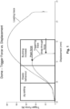
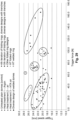
- High performance asymmetric bi-stable domes which provide high speeds in the [18 - 24] m/s range have a loading force in the range of 200 - 300 Newtons and a trigger force around 100 Newtons (i.e. an approximate weight of 10 kg at standard gravity acceleration), (See Figure 1 for a plot of trigger force versus displacement for a high performance dome). Trigger force may result in a discomfort both for the user who needs to provide the large device trigger force and the patient who feels the large device pressure on the skin when triggering.
- the devices of the present invention provide a mechanism to lower the force when triggering the application device to a comfortable range of approximately 10 - 25 Newtons, while preserving or increasing the dome's velocity, such that the dome may accelerate a 450 mg projectile (such as a microprojection array) to a velocity of approximately 18 - 24 m/s.
- the domes of the present invention are induced into a partially buckled state by encasing the dome in the applicator, such as by encasing the dome in an over-moulding.
- the dome may be encased by forming a plastic over-moulding of the dome's outer rim, by ultrasound crimping plastic ribs over the dome's outer rim, by over moulding a plastic vault with a pattern of stiffening ribs on the dome, by using a folded metal casing, by using a ceramic casing, or by self-encasement of the dome by folding back the dome's edges on itself, or a combination of these approaches.
- the devices of the present invention must have the dome correctly integrated into the housing so that the energy release generated by triggering the dome is funnelled toward the patch and not lost in random fluctuations.
- a dome without integration into the device without any encasement (continuous or tabbed metal ring or ultrasound crimping or other methods described herein) will "jump" in the device and as a consequence the acceleration of the patch will be adversely impacted.
- An efficient coupling of the dome to the patch results in efficient acceleration of the patch and a successful application of the patch to the skin.
- the dome may be made from an austenitic stainless steel strip (Sandvik 11R51, 0.3mm thick), laser cut in an approximately 31.1 mm diameter disc, with a centred, approximately 3.0 mm diameter hole.
- This particular type of steel has excellent spring properties, with a high tensile strength (2050 MPa), and high yield strength (0.2% offset yield strength of 1975 MPa).
- domes include diameters which range from about 5 to 80mm, or from about 5 to 70mm or from about 5 to 60mm or from about 5 to 50mm or from about 5 to 40mm or from about 5 to 30 mm or from about 5 to about 20 mm or from about 10 to 80mm, or from about 10 to 70mm or from about 10 to 60mm or from about 10 to 50mm or from about 10 to 40mm or from about 10 to 30 mm or from about 10 to about 20 mm or from about 20 to 80mm, or from about 20 to 70mm or from about 20 to 60mm or from about 20 to 50mm or from about 20 to 40mm or from about 20 to 30 mm or from about 30 to 80mm, or from about 30 to 70mm or from about 30 to 60mm or from about 30 to 50mm or from about 30 to 40mm or from about 40 to 80mm, or from about 40 to 70mm or from about 40 to 60mm or from about 40 to 80mm, or from about 40 to 70mm or from about 40 to 60mm or from about 40 to 50mm or from about 50 to 80mm, or from about
- the thickness of the dome may be from about 0.1 to 2mm or from about 0.1 to 1.5mm or from about 0.1 to 1.0mm or from about 0.1 to 0.5mm or from about 0.25 to 2mm or from about 0.25 to 1.5mm or from about 0.25 to 1.0mm or from about 0.25 to 0.5mm or from about 0.5 to 2mm or from about 0.5 to 1.5mm or from about 0.5 to 1.0mm or from about 0.75 to 2mm or from about 0.75 to 1.5mm or from about 0.75 to 1.0mm or from about 1.0 to 2mm or from about 1.0 to 1.5mm or from about 1.5 to 2.0mm.
- the hole diameter in the dome may be from about 0% to 70% of the dome or from about 0% to 60% of the dome or from about 0% to 50% of the dome or from about 0% to 40% of the dome or from about 0% to 30% of the dome or from about 0% to 20% of the dome or from about 0% to 10% of the dome or from about 10% to 70% of the dome or from about 10% to 60% of the dome or from about 10% to 50% of the dome or from about 10% to 40% of the dome or from about 10% to 30% of the dome or from about 10% to 20% of the dome or from about 20% to 70% of the dome or from about 20% to 60% of the dome or from about 20% to 50% of the dome or from about 20% to 40% of the dome or from about 20% to 30% of the dome or from about 30% to 70% of the dome or from about 30% to 60% of the dome or from about 30% to 50% of the dome or from about 30% to 40% of the dome or from about 40% to 70% of the dome or from about 40% to 60% of the dome or from about 40% to 50% of the dome or from about 30% to 40% of the dome or from about 40% to 70%
- the yield strength of the dome may be from about 400 to 3500MPa, or from about 400 to 3000Mpa, or from about 400 to 2500MPa or from about 400 to 2000Mpa, or from about 400 to 1500MPa, or from about 400 to 1000MPa, or from about 400 to 500Mpa, or from about 1000 to 3500MPa or from about 1000 to 3000Mpa, or from about 1000 to 2500MPa or from about 1000 to 2000Mpa, or from about 1000 to 1500MPa or from about 1500 to 3500Mpa, or from about 1500 to 3000MPa, or from about 1500 to 2500Mpa, or from about 1500 to 2000MPa, or from about 2000 to 3500MPa or from about 2000 to 3000MPa or from about 2000 to 2500 or from about 2000 to 3000MPa or from about 2000 to 2500 or from about 2500 to about 3500 or from about 2500 to about 3000..
- the tensile strength of the dome may be from about 250 to 2400MPa, or from about 250 to 2000Mpa, or from about 250 to 1500MPa or from about 250 to 1000Mpa, or from about 250 to 500MPa, or from about 500 to 2400MPa, or from about 500 to 2000Mpa, or from about 500 to 1500MPa or from about 500 to 1000Mpa, or from about 750 to 2400MPa or from about 750 to 2000Mpa, or from about 750 to 1500MPa or from about 750 to 1000Mpa, or from about 1000 to 2400MPa, or from about 1000 to 2000Mpa, or from about 1000 to 1500MPa, or from about 1500 to 2400MPa or from about 1500 to 200MPa.
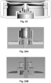
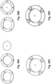
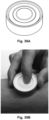
- the dome may be plastically deformed under 1 to 5 tons of pressure using a hydraulic press, into a spherical cap, using the specific tool T6.2 (See Figures 2A and 2B ) which can have an anti-wrinkling pressure pad added.
- This tool profile results in a high performance asymmetric bi-stable dome spring with a circumferentially flat lip which is 3.6mm wide and a domed central region, with an approximately 3 mm centre hole at the apex of the central region (See Figures 3A to 3B ).
- the transition radius between the lip and the dome central region is a fold line.
- a natural slight second curvature appears in the dome due to the anisotropy induced by the grain structure of the steel.
- the central region of the dome may be "loaded” by displacing it perpendicularly to the flat of the dome's base until the concavity inverts through buckling ("snap-through”).
- a “loader” can be used to load the dome, for example an approximately 15.3mm diameter plastic ring with a section of 1.3mm is pushed against the dome convex side until loading.
- This loaded dome may then be placed on a test jig (See Figures 4A to 4C ), comprised of a hollow cylinder for support around the unloaded flat circumferential region, with the convex surface rising in the vertical plane.
- a window in the jig enables the tracking of a 450 mg projectile accelerated by the dome actuation, via a high speed camera (40,000 fps).
- a motorised stage with a cell force enables the triggering of the dome at a constant speed of 50mm/min, while recording the applied load and deflection of the dome at the same time.
- the triggering is achieved with a plastic trigger having similar dimensions as the "loader".
- the dome may be considered a shell structure (a three-dimensional solid whose thickness is very small compared with its other dimensions).
- a compressive load is applied axially to the dome, its geometry evolves (i.e. deformation) under the increasing bending moment while accommodating the build-up of membrane and shear forces, and related stresses.
- This phase of deformation corresponds to the first elastic part of the force vs. displacement graph, where the resulting load on the dome increases linearly with the deformation (characterised by the apex displacement) (See Figure 1 ).
- some areas of the dome start to experience buckling, meaning that locally these areas become unstable and are poised to snap-through in order to minimise their energy level.
- the dome inverts in order to minimise the bending moment, shear and membrane stresses, and reaches a lower energetic state (the inverted state).
- the transient nature of the inversion results in a high acceleration and deceleration of the centre part of the dome (apex), which can be used as a high speed actuator to project a device such as a microprojection array.
- the final section of the graph displays the load collapse to zero as the dome goes faster than the motorised stage of the recording cell force.
- the user In order to trigger the dome, the user needs to bring the dome to this critical state where the buckling propagates to the full dome.
- the user applies a peak load which can be significantly higher than the snap-through force.
- the embodiment of the particular asymmetric bistable dome described above when non constrained (stand-alone dome) has a peak loading force of 195 ⁇ 2.85 N and speed around 11 m/s (loading speed) for a peak trigger force of 96 ⁇ 2.24 N, which results in an unloading speed of 20.80 ⁇ 1.34 m/s.
- This design provides a two-fold increase of the performance with a halving of the force resulting in the doubling of the speed (convention loading-triggering).
- the device of the present invention bring the dome close to this critically unstable state where a high ratio of the dome surface is buckling, ready to propagate to the full dome.
- close it is meant that a low remaining load still needs to be applied by the user to ultimately bring the dome to the critical state.
- the remaining force (“the trigger force”) needs to be tailored in order to fall in a range, where the maximum corresponds to a force which is considered too high to deliver by a user and/or to be received by a patient, and the minimum corresponds to a force which is not sufficient to prevent any unintentional triggering.
- the critical force can vary with imperfections in the dome (stamping, grain, defects, dints etc.), with the triggering (off-centring, angle, shape and size), with the dynamic of the triggering (low speed, high impact speed, vibrations) and stress variation (temperature, humidity, dilatation of steel/plastic). Therefore, some buffering needs to be considered in choosing the ends of the trigger force range.
- the range of the triggering force for a encased dome may be from 5 to 100N, or from 5 to 90N or from 5 to 80N, or from 5 to 70N or from 5 to 60N, or from 5 to 50N or from 5 to 40N, or from 5 to 30N or from 5 to 20N or from 5 to 10N, or from 10 to 100N, or from 10 to 90N or from 10 to 80N, or from 10 to 70N or from 10 to 60N, or from 10 to 50N or from 10 to 40N, or from 10 to 30N or from 10 to 20N, or from 20 to 100N or from 20 to 90N or from 20 to 80N, or from 20 to 70N or from 20 to 60N, or from 20 to 50N or from 20 to 40N, or from 20 to 30N or from 30 to 100N or from 30 to 90N or from 30 to 80N, or from 30 to 70N or from 30 to 60N, or from 30 to 50N or from 30 to 40N, or from 40 to 100N or from 40 to 90N or from 40 to 80N
- the range of the triggering force for an stand-alone dome may be from 100 to 200N, or from 100 to 190N or from 100 to 180N, or from 100 to 170N or from 100 to 160N, or from 100 to 150N or from 100 to 140N, or from 100 to 130N or from 100 to 120N, or from 100 to 110N or from 110 to 200N, or from 110 to 190N or from 110 to 180N, or from 110 to 170N or from 110 to 160N, or from 110 to 150N or from 110 to 140N, or from 110 to 130N or from 110 to 120N or from 120 to 200N, or from 120 to 190N or from 120 to 180N, or from 120 to 170N or from 120 to 160N, or from 120 to 150N or from 120 to 140N, or from 120 to 130N or from 130 to 200N, or from 130 to 190N or from 130 to 180N, or from 130 to 170N or from 130 to 160N, or from 130 to 150N or from 130 to 140N, or from 130 to 190N or from 130
- the range of the loading force for a encased dome may be from 100 to 400N, or from 100 to 350N or from 100 to 300N, or from 100 to 250N or from 100 to 200N, or from 100 to 200N or from 100 to 150N, or from 150 to 400N or from 150 to 350N, or from 150 to 300N or from 150 to 250N or from 150 to 200N, or from 200 to 400N or from 250 to 350N, or from 200 to 300N or from 200 to 250N, or from 250 to 400N or from 250 to 350N or from 250 to 300N or from 300 to 400N, or from 300 to 350N or from 350 to 400N.
- the range of the loading force for an stand-alone dome may be from 100 to 200N, or from 100 to 190N or from 100 to 180N, or from 100 to 170N or from 100 to 160N, or from 100 to 150N or from 100 to 140N, or from 100 to 130N or from 100 to 120N, or from 100 to 110N or from 110 to 200N, or from 110 to 190N or from 110 to 180N, or from 110 to 170N or from 110 to 160N, or from 110 to 150N or from 110 to 140N, or from 110 to 130N or from 110 to 120N or from 120 to 200N, or from 120 to 190N or from 120 to 180N, or from 120 to 170N or from 120 to 160N, or from 120 to 150N or from 120 to 140N, or from 120 to 130N or from 130 to 200N, or from 130 to 190N or from 130 to 180N, or from 130 to 170N or from 130 to 160N, or from 130 to 150N or from 130 to 140N, or from 120 to 130N or from 130 to 200
- the ratio of the triggering force to the loading force may be from about 1:100 or from about 1:90 or from about 1:80 or from about 1:70 or from about 1:60 or from about 1:50 or from about 1:40 or from about 1:30 or from about 1:20 or from about 1:10 or from about 1:5.
- the ratio of the triggering force to the loading force may be from about 1:100 to about 1:5 or from about 1:90 to about 1:5 or from about 1:80 to about 1:5 or from about 1:70 to about 1:5 or from about 1:60 to about 1:5 or from about 1:50 to about 1:5 or from about 1:40 to about 1:5 or from about 1:30 to about 1:5 or from about 1:20 to about 1:5 or from about 1:10 to about 1:5 or from about 1:100 to about 1:10 or from about 1:90 to about 1:10 or from about 1:80 to about 1:10 or from about 1:70 to about 1:10 or from about 1:60 to about 1:10 or from about 1:50 to about 1:10 or from about 1:40 to about 1:10 or from about 1:30 to about 1:10 or from about 1:20 to about 1:10.
- the domes of the present invention are brought to a state of stable partial buckling while transitioning from the unloaded to the loaded positions.
- This intermediate energetic state cannot be captured for a non-encased device as the state is highly transient due to the dynamics of snapping-through which makes the dome pass through this state, and reach instead the lower energetic state of the fully inverted dome.
- the user can apply a load from this state without having all the 100 N of load retransmitted to the user.
- This is achieved by encasing the unloaded dome, and by loading the dome in a casing.
- the casing may be designed such that the transition of the loading dome is stopped in the desired state close to critical stable intermediary energetic state.
- the casing needs to provide some load against the dome to keep it in this intermediary position and prevent the dome from transitioning to reach the lower energetic state of the fully inverted dome, most of the load is provided by the buckled partition of the dome, as demonstrated by the fact that an extra smaller load (the "trigger force") can be applied without resuming the full load of 100 N.
- the required trigger force is lower than for the unconstrained loaded position; however, the velocity the dome achieves on release is not prejudiced.
- the amount of constraint can be used to reduce the trigger force on a high performance dome (high speed) without sacrificing the velocity.
- a comparison between constrained (encased) and unconstrained (non-encased) domes show that the velocity of the constrained dome is slightly increased from [20.80 ⁇ 1.34] m/s to [22.3 ⁇ 1.07] m/s. This may due to the fact that most of the constrained dome (the buckled partition) is ready to snap-through, whereas in the case of the unconstrained dome some dynamic is lost in fluctuating vibrations around the critical state.
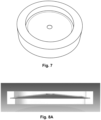
- One particular embodiment of the encapsulated dome is accomplished by over-moulding the outer rim of the dome in an appropriate material including but not limited to plastic, ceramic, aluminium metals, steel, glass, carbon fibers or combinations thereof prior to loading the dome (See Figures 5A and 5B , and Figures 6A to 6C for mould designs and Figure 7 and Figures 8A to 8C for an example of over moulded dome).
- Over moulding the dome with a plastic lends itself to integrating the overmoulded dome into a microprojection array applicator device. This design can be scaled-up for high-number throughput production at a low cost per part.
- the plastic dome-encasing material prevents the dome from transitioning from the unloaded state to the loaded states while maintaining the dome at the equilibrium state and maintains the dome in this desired state over the shelf-life of the device (high creeping resistance).
- the devices of the present invention are capable of being stored for long periods of time without the dome transitioning from the unloaded state to the loaded state.
- the devices of the present invention may be stored without transitioning from the unloaded state to the loaded state for at least about 6 months or about 1 year or about 2 years or about 3 years or about 4 years or about 5 years or about 6 years or about 7 years or about 8 years or about 9 years or about 10 years or more.
- the devices of the present invention may be stored without transitioning from the unloaded state to the loaded state for about 1 year to 20 years or from 1 year to 15 years or from 1 year to 10 years or from 1 year to 5 years or from 2 years to 20 years or from 2 years to 15 years or from 2 year to 10 years or from 2 year to 5 years or from 3 years to 20 years or from 3 year to 15 years or from 3 year to 10 years or from 3 year to 5 years or from 4 years to 20 years or from 4 year to 15 years or from 4 years to 10 years or from 4 year to 5 years or from 5 years to 20 years or from 5 years to 15 years or from 5 years to 10 years or from 10 years to 20 years or from 15 years to 20 years.
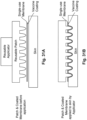
- the dome-encasing material should have high impact strength to sustain the shock of the inverting dome while loading. Loading and maintaining the dome in its desired state can be achieved in at least two ways, stiff or flexible encasing designs (see Figures 9A and 9B ).
- First provide an over moulding which restrains the bending of the dome. This approach enables an easy tailoring of the bending of the dome by varying the dimensions of the dome-encasing material, and hence the compliance of the material. Having flexible parts, however, may not be the most favourable design in an applicator.
- Second, providing a stiff dome-encasing material that holds a part of the dome tightly at some anchoring points of the dome e.g.
- dome-encasing material such as plastics with high flexural modulus (> 10GPa) are preferred.
- Plastics that can be used in the casing for the domes include but are not limited to 15%-50% glass reinforced nylon 6, 40% glass reinforced polyphenylene sulphide (PPS) and 50% GF PBT (polybutylene) or PBT/PET blends (polybutylene and polyethylene terephthalate).
- PPS glass reinforced polyphenylene sulphide
- GF PBT polybutylene
- PBT/PET blends polybutylene and polyethylene terephthalate
- Other dome-encasing materials that can be used in the devices and methods of the present invention include but are not limited to ceramic, aluminium (powder metallurgy, reinforced plastic with steel, glass or carbon fibres or a combination thereof.
- the over moulded portion of the device will depend in part on the diameter of the dome it encases.
- the diameter of the over moulding may be from about 5 to 100mm, or from about 5 to 90mm or from about 5 to 80mm or from about 5 to 70mm or from about 5 to 60mm or from about 5 to 50 mm or from about 5 to about 40 mm or from about 5 to 30mm or from about 5 to 20 mm or from about 5 to about 10 mm or from about 10 to 100mm, or from about 10 to 90mm about 10 to 80mm, or from about 10 to 70mm or from about 10 to 60mm or from about 10 to 50mm or from about 10 to 40mm or from about 10 to 30 mm or from about 10 to about 20 mm or from about 20 to 80mm, or from about 20 to 70mm or from about 20 to 60mm or from about 20 to 50mm or from about 20 to 40mm or from about 20 to 30 mm or from about 30 to 80mm, or from about 30 to 70mm or from about 30 to 60mm or from about 30 to 50mm or from about
- the thickness of the overmoulding may be from about 1 to 30mm or from about 1 to 25mm or from about 1 to 20mm or from about 1 to 15mm or from about 1 to 10mm or from about 1 to 5mm or from about 5 to 30mm or from about 5 to 25mm or from about 5 to 20mm or from about 5 to 15mm or from about 5 to 10mm or from about 10 to 30mm or from about 10 to 25mm or from about 10 to 20mm or from about 10 to 15mm or from about 15 to 30mm or from about 15 to 25mm or from about 15 to 20mm or from about 20 to 30mm or from about 20 to 25mm or from about 25 to 30mm.
- the over moulding of the dome will encroached on the dome for about 1 to 30mm or from about or from about 1 to 25mm or from about 1 to 20mm or from about 1 to 15mm or from about 1 to 10mm or from about 1 to 5mm or from about 5 to 30mm or from about 5 to 25mm or from about 5 to 20mm or from about 5 to 15mm or from about 5 to 10
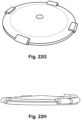
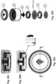
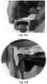
- the primed dome is held is in place in the housing and/or applicator by using ultrasound crimping to encase the flattened edge of the dome is the housing (See Figures 37 and 38 ).
- the ultrasound crimping may be used to crimp a portion of the housing (such as a plastic rib as shown in Figure 37A and 37B ) over the flattened edge of the dome to hold the dome in place.
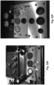
- Figure 39A shows the top view of a picture of an applicator for a microprojection array
- Figure 39B shows a top view of a picture of an applicator in which the microprojection array is being applied to a patient's skin.
- the top of the applicator is a collapsible trigger mechanism which triggers the dome to release the microprojection array if the trigger mechanism is pressured with enough force to activate the dome.
- the dome is activated it can impact the microprojection array such that the array can be propelled from the applicator into the patient's skin.
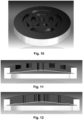
- the dome can be over-moulded with a plastic vault with a pattern of ribs (See Figures 10 to 12 ).
- a plastic vault could be incorporated in a 3 steps process in the same mould:
- the pattern of plastic vault and ribs enables the stiffening and holding of the dome in place and prevent creeping.
- the use of ribs instead of a solid body reduces the need for too much extra material.
- the fact that the ribs do not touch the domes leads to a simple moulding process as the exact shape of the domes need not be known and thus the ribs can vary slightly.
- the cavity between the dome and the ribs may be filled by a covering plastic vault. It may be useful to provide a coating to avoid adhesion of the metal dome with the plastic vault. (Coating on the dome, on the plastic, or both).
- Figure 10 shows a dome casing with an over moulded vault with ribs.
- the dome in grey is first moulded in the unloaded state (white plastic), then while still in the mould the dome is pushed until loading, then a second over moulding occurs over the convex side of the over moulded dome. It may also be useful to provide some tiny holes in the plastic in order to prevent shrinkage of the ribs (thicker section otherwise), and allow some venting for the dome (See Figure 12 ).
- the holes may be made by small pins such that the pins are sufficiently small so that the contacting section with the dome can be kept to a simple compliant contacting shape.
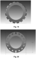
- a foldable metal ring which envelopes the outer edge of the dome.
- a metal strip of thickness 0.5 mm to 2 mm may be cut into a ring that can be folded back onto the dome, see Figures 13 to 21 .
- the foldable metal ring can have tabs or can be a continuous ring without tabs.
- the metal strip may be made of but is not limited to any steel, stainless steel, aluminium or any other metal. It is preferred that a metal that can be bend without too much spring back and able to sustain a load on the loaded dome is selected.
- the metal strip can be cut by punch tool, laser cut or waterjet cut for example.
- the design of the foldable ring is such that the inner diameter 1 (ID1) enables the unloaded (and triggered) dome to sit flush on the ring (see Figure 13 ), and the design of the extended radial tabs such as that when folded the tabs extend to hold back the dome to fully load and set the dome to its desired trigger force in a way similar to that described above for the over-moulded dome.
- the foldable metal ring may encompass the entire dome edge or portions thereof. This extension can be characterised by another inner diameter 2 (ID2).
- Figure 21A shows a primed dome in a metal ring with three tabs and Figure 21B shows the dome inserted in an injected moulded applicator.
- the hardness of the steel used for the dome is from about 500 to about 650 HV (Vickers Hardness) pre-heat treatment.
- the hardness of the steel used for the dome may be from about 400 to about 750 HV or from about 450 to about 750 HV or from about 500 to about 750 HV or from about 550 to about 750 HV or from about 600 to about 750 HV or from about 650 to about 750 HV or from about 700 to about 750 HV or from about 400 to about 700 HV or from about 450 to about 700 HV or from about 500 to about 700 HV or from about 550 to about 700 HV or from about 600 to about 700 HV or from about 650 to about 700 HV or from about 400 to about 650 HV or from about 450 to about 650 HV or from about 500 to about 650 HV or from about 550 to about 650 HV or from about 550 to about 600 HV or from about 600 to about 750 HV or from about 600 to about 700 HV or from about 600 to about
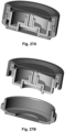
- the process for making the encased dome can be accomplished with a first vertical bending of the tabs in a punch tool, followed by folding the tabs down onto the dome, see Figures 22A to 22H .
- a thin ring with fewer tabs may provide similar performance compared to thicker foldable metal rings with more tabs while providing for a lower weight and lower cost.
- the ID between the closed tabs may be the dominant parameter for the tailoring of the trigger force.
- the tool forces the tabs to close with an ID ⁇ of between 26.7- 26.8 mm.
- the encasement may comprise two metal rings which may be attached to the outer edge of the dome by welding or by constructing the ring with a pocket for the dome.
- the cover ring is tailored to the right ID to control the trigger force and the dome is sandwiched by the two rings clamped together by screws or other attachment devices for holding the rings and dome together. See Figure 30 . By changing the depth of the pocket and the IDs of the rings different performances can be achieved.
- the foldable metal rings may be from about 0.1mm to about 5 mm, or from about 0.1mm to about 4.5mm, or from about 0.1mm to about 4 mm, or from about 0.1mm to about 3.5mm, or from about 0.1mm to about 3 mm, or from about 0.1mm to about 2.5mm, or from about 0.1mm to about 2 mm, or from about 0.1mm to about 1.5mm, or from about 0.1mm to about 1 mm, or from about 0.1mm to about 0.5mm, or from about 0.2mm to about 5 mm, or from about 0.2mm to about 4.5mm, or from about 0.2mm to about 4 mm, or from about 0.2mm to about 3.5mm, or from about 0.2mm to about 3 mm, or from about 0.2mm to about 2.5mm, or from about 0.2mm to about 2 mm, or from about 0.2mm to about 1.5mm, or from about 0.2mm to about 1 mm, or from about 0.2mm to about 0.5mm, or from about 0.3mm to about 5 mm,
- the number of tabs in the foldable metal ring can be from 2 to 20 or from 2 to 19 or from 2 to 18 or from 2 to 17 or from 2 to 16 or from 2 to 15 or from 2 to 14 or from 2 to 13 or from 2 to 12 or from 2 to 11 or from 2 to 10 or from 2 to 9 or from 2 to 8 or from 2 to 7 or from 2 to 6 or from 2 to 5 or from 2 to 4 or from 2 to 3 or from 3 to 20 or from 3 to 19 or from 3 to 18 or from 3 to 17 or from 3 to 16 or from 3 to 15 or from 3 to 14 or from 3 to 13 or from 3 to 12 or from 3 to 11 or from 3 to 9 or from 3 to 8 or from 3 to 7 or from 3 to 6 or from 3 to 5 or from 3 to 4 or from 4 to 20 or from 4 to 19 or from 4 to 18 or from 4 to 17 or from 4 to 16 or from 4 to 15 or from 4 to 14 or from 4 to 13 or from 4 to 12 or from 4 to 11 or from 4 to 10 or from 4 to 9 or from 4 to 8 or from 4 to 7 or
- the performance of the encased dome may be improved with respect to speed, force and stability by conditioning the dome and the foldable metal ring in which it is encased.
- the encased domes may be treated with a heat treatment.
- the heat may be from about 300°C to about 475°C or from about 300°C to about 450°C or from about 300°C to about 425°C or from about 300°C to about 400°C or from about 300°C to about 350°C or from about 350°C to about 500°C or from about 350°C to about 475°C or from about 350°C to about 450°C or from about 350°C to about 425°C or from about 350°C to about 400°C or from about 375°C to about 500°C or from about 375°C to about 475°C or from about 375°C to about 450°C or from about 375°C to about 425°C or from about 400°C to about 500°C or from about 400°C to about 475°C or
- the duration of the heating may be from about 1 hour to about 6 hours or from about 1 hour to about 5 hours or from about 1 hour to about 4 hours or from about 1 hour to about 3 hours or from about 1 hour to about 2 hours or from about 2 hour to about 6 hours or from about 2 hour to about 5 hours or from about 2 hour to about 4 hours or from about 2 hour to about 3 hours or from about 3 hour to about 5 hours or from about 3 hour to about 4 hours or from about 4 hour to about 6 hours or from about 4 hours to 5 hours.
- the dome and the foldable metal ring encasing the dome may be tempered dome at 425°C for 4h and then freely cooled in the furnace.
- the metal strip may be part of the dome itself.
- the outer lip of the dome can be folded over in a variety of ways to effect an over-moulded dome arrangement.
- encase the dome include but are not limited to by forming a plastic over-moulding of the dome outer rim, by over moulding a plastic vault with a pattern of stiffening ribs on the dome, by using a folded metal casing, by using a ceramic casing, or by self-encasement of the dome by folding back the dome's edges on itself, or a combination of these approaches.
- the dome system can be a stand-alone system or a part of an applicator system such as when the system is inserted in an applicator.
- the overmoulded dome is placed between the applicator trigger (e.g. flexible top of the applicator) and the microprojection patch held in the patch attach inner mechanism.
- the dome system could be part of a sub-assembly of the applicator (e.g. dome overmoulded in the top assembly or an overmoulded metal ring folded over the dome in the top assembly.
- Figure 23 shows a design of MAP applicator where the dome system (overmoulded dome) is a stand-alone part positioned between the flexible/collapsable top of the applicator and the microprojection patch attach inner mechanism.
- the top of the applicator acts as the trigger against the dome, but also acts as part of the guiding system of the patch due to an inner spigot that protrudes from the flexible top and inserts in the patch through the centre hole of the encased dome.
- a slight gap is visible between the dome and the head of the patch which enables the release of the patch from its position in the applicator only when the dome starts to transition, and not before pressure from the user is placed on the applicator's flexible top.
- Figures 24A to 24E demonstrate different embodiments of the patch attach inner mechanisms. All of these dome system designs provide an efficient way of storing the energy in the dome so as to release the patch from its attachment and accelerate the microprojection array to high speeds, while requiring only a small force from the user to trigger the applicator.
- Figure 25 is a photograph of an embodiment of the MAP applicator in its packaging. This embodiment of the applicator is very compact having a diameter of 38mm and a height of 15.8mm, which provides a user friendly device with less waste generation and raw material use.
- the devices and methods of the present invention provide a compact dense energy system, with a low trigger actuation providing a high acceleration over a small span.
- a traditional applicator capable of achieving such speeds would require a 10cm long bulky applicator in order to be able to hold the spring compressed, and accelerate over a long path to propel the patch to the desired speed.
- a MAP applicator based on the encased dome can incorporate the sterile and low water ingress barrier and keep the coated MAP in a small dry sterile inner environment.
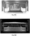
- barriers and seal designs can be incorporated into the applicator devices as seen in Figures 26A, 26B , 27A, 27B , 28A and 28B .
- the parameters for delivering the microprojection array may be, but are not limited to: application momentum 6 - 22 g ⁇ m ⁇ s-1, application momentum per projection 1 - 4 mg m s-1, application energy 65 - 165 mJ; application energy per projection 10 - 40 ⁇ J; dome mass 0.5 - 2 g; patch velocity 15 - 24 m s-1.
- the parameters for the patch may include patch mass 265 - 1400 mg; patch number of projections 1,000-21,000; tip radius can be from 1 to 100 ⁇ m; patch size 4x4 mm to 11 ⁇ 11 mm (round diameter of 10mm); length of projection 100-300 ⁇ m; base width 20-100 ⁇ m; projection spacing 70-185 ⁇ m; projection density 10-200 projections/mm 2 .
- the speed of the microprojection array as it is projected into the skin depends at least in part upon the density of the projections in the microarray and the area of the array.
- the range of speeds for the microprojection array entering the skin may be from about 10 m/s to about 50 m/s or from about 10 m/s to about 40 m/s or from about 10 m/s to about 30 m/s or from about 10 m/s to about 25 m/s or from about 10 m/s to about 20 m/s or from about 20 m/s to about 50 m/s or from about 20 m/s to about 40 m/s or from about 20 m/s to about 30 m/s or from about 25 m/s to about 50 m/s or from about 25 m/s to about 40 m/s or from about 25 m/s to about 30 m/s.
- the speed of the microprojection array is at least 15 m/s or at least 20
- the microprojection arrays that the applicator of the present invention projects into the skin may have a variety of shapes and sizes.
- the microprojection array may be square, circular, rectangular or irregular depending on its use.
- the microprojection arrays can be varied in size depending on its use.
- the area of the patch will have an impact on the ability to penetrate the subject, but this must be balanced by the need to induce cell damage over a sufficiently large area to induce a response. Consequently the patch typically has an area of between 0.5 ⁇ 0.5 mm and 20 ⁇ 20 mm, between 0.5 ⁇ 0.5 mm and 15 ⁇ 15 mm and more typically between 1 ⁇ 1 mm and 10 ⁇ 10 mm.
- the microprojection array is 10 ⁇ 10mm.
- the microprojection arrays may have a density of projections of between 1,000 to 20,000 per cm 2 or from 1,000 to 15,000 per cm 2 , or from 1,000 to 10,000 per cm 2 for from 1,000 to 5,000 per cm 2 , or from 2,500 to 20,000 per cm 2 or from 2,500 to 15,000 per cm 2 or from 2,500 to 10,000 per cm 2 or from 2,500 to 7,500 per cm 2 or from 2,500 to 5,000 per cm 2 or from 5,000 to 20,000 per cm 2 or from 5,000 to 15,000 per cm 2 or from 5,000 to 10,000 per cm 2 or from 5,000 to 9,000 per cm 2 or from 5,000 to 8,000 per cm 2 or from 5,000 to 7,000 per cm 2 or from 5,000 to 6,000 per cm 2 .
- the applicators of the present invention are often utilized to project high density microprojection arrays into the skin.
- Such high density arrays are microprojection arrays of sufficient size and density such that forces that can be applied manually will be insufficient to overcome the elasticity of the skin.
- the projections are typically separated by between 10 ⁇ m and 200 ⁇ m, between 30 ⁇ m and 150 ⁇ m, between 50 ⁇ m and 120 ⁇ m and more typically between 70 ⁇ m and 100 ⁇ m, leading to patches having between 10 and 1000 projections per mm 2 and more typically between 100 and 3000 projections per mm 2 , and in one specific example approximately 20,000 per cm 2 .
- the length of the projections may be from 100 ⁇ m to 700 ⁇ m or from 100 ⁇ m to 600 ⁇ m or from 100 ⁇ m to 500 ⁇ m or from 100 ⁇ m to 400 ⁇ m or from 100 ⁇ m to 300 ⁇ m or from 100 ⁇ m to 250 ⁇ m or from 100 ⁇ m to 200 ⁇ m or from 150 ⁇ m to 700 ⁇ m or from 150 ⁇ m to 600 ⁇ m or from 150 ⁇ m to 500 ⁇ m or from 150 ⁇ m to 400 ⁇ m or from 150 ⁇ m to 300 ⁇ m or from 150 ⁇ m to 250 ⁇ m or from 150 ⁇ m to 200 ⁇ m or from 200 ⁇ m to 700 ⁇ m or from 200 ⁇ m to 600 ⁇ m or from 200 ⁇ m to 500 ⁇ m or from 200 ⁇ m to 400 ⁇ m or from 200 ⁇ m to 300 ⁇ m or from 200 ⁇ m to 250 ⁇ m or from 225 ⁇ m to 700 ⁇ m or from 225 ⁇ m to 600 ⁇ m or from 225 ⁇ m to 500 ⁇ m or from 225 ⁇ m to 400 ⁇ m or from 225 ⁇ m to 300 ⁇ m or from 225 ⁇ m to 250 ⁇ m or from 225 ⁇ m to
- the projections may have a step shoulder between the cone and pillar of the projection.
- the microprojection array may be made of any suitable materials including but not limited to silicon, polymers, and plastic.
- the base thickness is about 60 um or silicon with a thin (1mm) polymer backing.
- the overall mass of some embodiments of the microprojection array is about 0.3 gm.
- the microprojection array may have bevelled edges to reduce peak stresses on the edge of the array.
- the patch can be quartered or subdivided by other ratios to reduce the stress load on the patch and mitigate patch breakage. Polymer embodiments may have reduced mass.
- the microprojection array may also have an overall weakly convex shape of the patch to improve the mechanical engagement with skin and mitigate the effect of high speed rippling application: a 'high velocity/low mass' system.
- the microprojection array may have a mass of less than 1 gram, or less than 0.9 grams or less than 0.8 grams or less than 0.7 grams, or less than 0.6 grams or less than 0.5 grams or less than 0.6 grams, or less than 0.5 grams or less than 0.4 grams or less than 0.3 grams or less than 0.2 grams or less than 0.1 grams or less than 0.05 grams.
- the microprojection array may have a mass of about 0.05 grams to about 2 grams, or from about 0.05 grams to about 1.5 grams or from about 0.05 grams to about 1.0 grams or from about 0.05 grams to about 0.9 grams, or from about 0.05 grams to about 0.8 grams or from about 0.05 grams to about 0.7 grams, or from about 0.05 grams to about 0.6 grams or from about 0.05 grams to about 0.5 grams or from about 0.05 grams to about 0.4 grams, or from about 0.05 grams to about 0.3 grams or from about 0.05 grams to about 0.2 grams, or from about 0.05 grams to about 0.1 grams or from about 0.1 grams to about 1.0 grams or from about 0.1 grams to about 0.9 grams, or from about 0.1 grams to about 0.8 grams or from about 0.1 grams to about 0.7 grams, or from about 0.1 grams to about 0.6 grams or from about 0.1 grams to about 0.5 grams or from about 0.1 grams to about 0.4 grams, or from about 0.1 grams to about 0.3 grams or from about 0.1 grams to about 0.2 grams. In one embodiment of the applic
- the parameters for delivering the microprojection array may be: application momentum 6 - 22 g ⁇ m ⁇ s-1, application momentum per projection 1 - 4 mg m s-1, application energy 65 - 165 mJ; application energy per projection10 - 40 ⁇ J; dome mass 0.5 - 2 g; patch velocity 15 - 24 m s-1.
- the parameters for the patch may include patch mass 265 - 1400 mg; patch number of projections 5,000-21,000; tip radius; patch size 4x4 mm to 11 ⁇ 11 mm (round diameter of 10mm); length of projection 100-300 ⁇ m; base width 20-50 ⁇ m; projection spacing 70-185 ⁇ m; projection density 10-200 projections/mm 2 .
- the present invention relates to microprojection array applicators that provide application of microprojection arrays to the skin for the delivery of substances in particular the delivery of vaccine antigens.
- the applicators of the present invention are especially useful for the delivery of high density microprojection arrays to the skin surface.
- the applicators of the present invention are also useful for the delivery of high density microprojection arrays at a high rate of speed to the skin surface.
- the present invention is designed to achieve tolerable penetration for high density, low mass microprojection arrays (> 5,000 /cm 2 ) that are delivered to the skin at high velocities.
- the applicators of the present invention are comprised of a sterile housing in which an encased dome and one or more microprojection array(s) are contained.
- the housing may preferably be made of plastic or a metallic material such as steel or aluminium or a fibrous paper based material or a laminate including any of these materials.
- the bottom of the microprojection array applicator is covered with a foil sheet to protect the membrane and to keep the device sterile.
- the housing encompasses the inner workings of the applicator.
- the housing has an upper and lower section.
- the housing may have a collapsible section which acts as a trigger to activate the dome(s).
- the collapsible section or sections of the housing may be on upper section of the device or incorporated into the bottom of the housing.
- the flexible or collapsible section of the housing is actuated through a force applied by hand such that application of the microprojection array is comfortable to both the patient and the person activating the applicator.
- the force is applied to the applicator in a fashion that is substantially perpendicular to the skin to which the microprojection array is applied such that the force travels down through the encased dome.
- the activation force could be applied in a direction substantially parallel to the skin by a mechanism that may be actuated between the thumb and forefinger. The mechanism by which the applicator is activated should not cause discomfort to the patient.
- the microprojection array is propelled from the device after the device is activated such that the microprojection array transits a distance between the applicator device and the target skin and then penetrates the skin. In essence, the microprojection array is propelled across some distance and then penetrate the target skin.
- the applicator where the microprojection array is discharged from the device the microprojection array is tethered to a mechanism that protrudes through the dome such that when the dome is activated the mechanism releases the microprojection array with sufficient force to propel the array into the skin.
- the microprojection array could be fixed to a guide shaft (spigot) that fits through a center hole in the dome.
- the spigot enables guided travel of the microprojection array to ensure that the microprojection array contacts the skin in a flat manner, so that the microprojection array and the skin meet flush.
- the microprojection array and the dome are disconnected such that the large mass of the ring is not attached to the array. This should permit a high speed, low mass, pain free delivery of the microprojection array to the skin.
- the microprojection array may be attached to a low mass tether.
- the microprojection array is either not in direct contact with the dome or the only contact between the dome and the microprojection array is when the dome impacts the array sending the array toward the skin. In these cases the microprojection array can be struck at the point where the dome achieves maximum velocity and the mass of the dome does not impact the skin of the patient.
- the patch insertion and flight guiding are accomplished with springs instead of a sliding spigot (See Figures 34A to 34G ).
- Another alternative is to insert the patch directly in the dome instead of utilizing a separate part by having the spring feature incorporated into the dome. This embodiment can be by manufactured by laser cutting the domes (See Figure 35 ).
- the present invention further relates to microprojection applicators in which a membrane is introduced between the microprojection array and the skin surface to which the array is applied.
- the membrane flattens the skin to which the microprojection array is applied and absorbs the initial impact from the microprojection applicator.
- the use of a membrane results in an even surface for application regardless of skin condition or thickness and provides even penetration of the microprojections across the skin surface.
- Microprojection application through a membrane has distinct advantages over application of a microprojection array directly into the skin. It allows the skin to be smoothed flat creating a consistent and uniform application surface.
- the use of a membrane over the microprojection array allows a device design whereby the microprojection array can be kept in a sterile environment until the membrane is pierced at the time of application.
- the membrane also allows the patch to be removed from the skin with the applicator and provides confirmation of the application of the microprojection array via the penetration pattern visible on the membrane surface.
- the membrane also reduces the need for external packaging to maintain sterility thereby reducing packaging waste.
- the membrane is non-permeable.
- the membrane may be made of but is not limited to polymer films, organic and organic fiber films or laminates.
- the membrane is from about 2 to about 20 ⁇ m or from about 5 to 20 ⁇ m or from about 10 to about 20 ⁇ m or from about 5 to 10 ⁇ m in thickness.
- the microprojections of the microprojection array may be uncoated and the membrane may be coated by a substance such as a vaccine.
- the applicator pushes the microprojections of the microprojection array through the vaccine coated membrane thereby delivering the vaccine to the skin of a patient by penetrating the membrane.
- the membrane and microprojection array may be designed such that the microprojections do not penetrated the membrane but rather force the membrane into the skin where the vaccine can be delivered.
- the tips of the microprojections may be modified so that they are not so sharp as to penetrated the membrane but still strong enough to penetrate the skin (See Figure 31 ).
- the ductile membrane with the vaccine coating on the side of the membrane facing the skin will form a disposable element forming an impenetrable barrier between the microprojections and the skin during application.
- the coated membrane delivers the coating to the skin via the patch microprojections locally deforming but not penetrating the membrane.
- the entire applicator or parts of the applicator may be re-usable.
- the membrane may be coated by various coating techniques including but not limited to gas-jetting or inkjet coating or other printing means.
- the coating may be applied as a layer or as "dots" on the membrane that align with the microprojections of the microprojection array.
- the membrane may be dissolvable and provide for an extended release of coating into the skin.
- the membrane may also be covered by a label or covering which serves to protect and keep sterile the membrane and the microprojection array.
- the label may be in the form of a foil seal or a mesh that can be removed just prior to the use of the microprojection array applicator. In embodiments where a membrane is not used the label may cover the microprojection array.
- microprojection arrays to deliver vaccines to the skin may cause erythema, oedema and visual discoloration of the skin
- various substances could be added to the applicator, for example between the membrane and the foil seal or mesh. See Figures 32A to 32D .
- the substances could be impregnated in the membrane or foil seal/mesh.
- Such substances include but are not limited to moisturizing gel, sterilizing gel, anaesthetic agents, antibiotics, anti-inflammatory agents, therapeutic or prophylactic substances to improve wound healing or combinations thereof.
- the substances could include vaccine adjuvants or dyes to reduce the visual impact of erythema or dyes to indicate delivery of the vaccine or dyes to indicate what vaccine has been delivered.
- a desiccant film may be included in the microprojection array applicator to maintain the internal environment and water content of the coating.
- One method of incorporating a desiccant into the applicator is by incorporating the desiccant into the membrane which may be layered under the foil seal or internal to the device housing.
- a high performance dome was tested for [11R51 0.3mm steel - T6.2 stamping profile], standalone performance which is controlled displacement at constant speed, load recording.
- the loading of the dome is the black trace and the triggering of the dome is the blue trace. Different zones of strain-stress (jig setting, elastic behaviour and buckling increase are explained on the triggering trace.
- Performance loading of the dome 11.32 m/s for 197.89 N; triggering 22.17 m/s for a peak force (trigger force) of 95.46 N.
- Figure 1 is a graph that shows the triggering of a high performance dome [11R51 0.3mm - T6.2], that has been over moulded with 15% Glass filled nylon 6 high impact - dimensions [OD ⁇ 33.4mm, thickness 4.9mm, convex ID ⁇ 27.9, concave ID ⁇ 27.1 (of the loaded dome)).
- the beginning of the graph is an artefact from the test method: the jig and the sample are loaded at 2N and permitted to settle, then the displacement was reset to zero and the load was then increased.
- the end of the graph corresponds to the cell force losing contact with the dome when it triggers, and following rebounds.
- Performance 23.36 m/s for a peak force (trigger force) of 20.62 N.
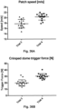
- the graph in Figure 29 shows the trigger force versus trigger speed for a variety of conditions and dome designs including treating the domes with heat and various gases.
- the normal plain untreated new dome is centred around a trigger speed of 20 ⁇ 2m/s with a trigger force of 100N.
- the trigger speed increases and force trigger force decreases to 24 ⁇ 2m/s and 70N respectively. Dome stability is also improved.
- the speed is preserved in the 20 ⁇ 2m/s range but the force can be tailored down to anywhere between 0- 60N, a beneficial increase in speed may take place for lower forces.
- the folded domes also experience a decrease in trigger force to about 20- 40 N and an increase in speed up to 25 to 26 m/s.
- the speed of the dome is preserved in the 20 ⁇ 2m/s range but the force can be tailored down to anywhere between 0 to 60N, an increase in speed may take place for lower forces.
- engineering plastics are required.
- any indication that a feature is optional is intended provide adequate support (e.g., under 35 U.S.C. 112 or Art. 83 and 84 of EPC) for claims that include closed or exclusive or negative language with reference to the optional feature.
- Exclusive language specifically excludes the particular recited feature from including any additional subject matter. For example, if it is indicated that A can be drug X, such language is intended to provide support for a claim that explicitly specifies that A consists of X alone, or that A does not include any other drugs besides X. "Negative" language explicitly excludes the optional feature itself from the scope of the claims.
- Non-limiting examples of exclusive or negative terms include “only,” “solely,” “consisting of,” “consisting essentially of,” “alone,” “without”, “in the absence of (e.g., other items of the same type, structure and/or function)" "excluding,” “not including”, “not", “cannot,” or any combination and/or variation of such language.
- a dog is intended to include support for one dog, no more than one dog, at least one dog, a plurality of dogs, etc.
- qualifying terms that indicate singularity include “a single”, “one,” “alone”, “only one,” “not more than one”, etc.
- qualifying terms that indicate (potential or actual) plurality include “at least one,” “one or more,” “more than one,” “two or more,” “a multiplicity,” “a plurality,” “any combination of,” “any permutation of,” “any one or more of,” etc.
Landscapes
- Health & Medical Sciences (AREA)
- Engineering & Computer Science (AREA)
- Dermatology (AREA)
- Medical Informatics (AREA)
- Anesthesiology (AREA)
- Biomedical Technology (AREA)
- Heart & Thoracic Surgery (AREA)
- Hematology (AREA)
- Life Sciences & Earth Sciences (AREA)
- Animal Behavior & Ethology (AREA)
- General Health & Medical Sciences (AREA)
- Public Health (AREA)
- Veterinary Medicine (AREA)
- Manufacturing & Machinery (AREA)
- Mechanical Engineering (AREA)
- Media Introduction/Drainage Providing Device (AREA)
- Prostheses (AREA)
- Surgical Instruments (AREA)
Claims (14)
- Vorrichtung zum Applizieren eines Mikroprojektions-Arrays an die Haut eines Säugetiers, wobei die Vorrichtung umfasst:a) ein Gehäuse;b) einen zusammendrückbaren Auslöser, der mit einer vorgespannten Kuppel verbunden ist; undc) eine Feder, die an dem Mikroprojektions-Array befestigt ist, wobei die vorgespannte Kuppel in dem Gehäuse eingeschlossen ist, so dass die Kuppel von einer gespannten Position in eine ungespannte Position übergeht, wenn der Auslöser zusammengedrückt wird, wodurch der Mikroprojektions-Array in die Haut des Säugetiers getrieben wird,dadurch gekennzeichnet, dass
der Mikroprojektions-Array durch einen Raum zwischen der Vorrichtung und der Haut des Säugetiers angetrieben wird, wobei das Einführen des Mikroprojektions-Array und ihre Flugführung durch die Feder erfolgt. - Vorrichtung nach Anspruch 1, wobei die Kuppel eine abgeflachte Außenkante hat.
- Vorrichtung nach Anspruch 2, wobei das Gehäuse, das die abgeflachte Außenkante der Kuppel umgibt, einen Teil der abgeflachten Kante der Kuppel umschließt.
- Vorrichtung nach Anspruch 2 oder Anspruch 3, wobei die abgeflachte Außenkante der Kuppel umlaufend ist.
- Vorrichtung nach einem der Ansprüche 1 bis 4, wobei die Vorrichtung ferner einen Foliendeckel (6) umfasst, der eine Öffnung in einer Basis des Gehäuses abdeckt, die bei der Verwendung in Kontakt mit der Hautoberfläche vorgesehen ist.
- Vorrichtung nach Anspruch 5, wobei der Foliendeckel (6) eine oder mehrere Substanzen enthält.
- Die Vorrichtung nach Anspruch 6, wobei die Substanz ein Trockenmittel ist.
- Vorrichtung nach einem der Ansprüche 1 bis 7, wobei die Kuppel aus austenitischem Stahl mit einer Dicke von 0,1 bis 0,5 mm hergestellt ist.
- Vorrichtung nach Anspruch 8, wobei die Kuppel 0,3 mm dick ist.
- Vorrichtung nach einem der Ansprüche 1 bis 9, wobei der Mikroprojektions-Array mit 10-30 m/s angetrieben wird.
- Vorrichtung nach Anspruch 10, wobei der Mikroprojektions-Array mit 20-26 m/s angetrieben wird.
- Vorrichtung nach einem der Ansprüche 1 bis 11, wobei der Mikroprojektions-Array eine Masse von 0,1 g bis 0,3 g hat.
- Vorrichtung nach einem der Ansprüche 1 bis 12, wobei die Kuppel wärmebehandelt wurde.
- Vorrichtung nach Anspruch 13, wobei die Wärmebehandlung bei etwa 300°C bis 450°C erfolgt.
Priority Applications (3)
| Application Number | Priority Date | Filing Date | Title |
|---|---|---|---|
| EP24222213.1A EP4548954A3 (de) | 2017-08-04 | 2018-08-03 | Kompakter hoher mechanischer energiespeicher und aktuator mit geringer auslösekraft für die abgabe von mikroprojektions-array-patches (map) |
| EP22214247.3A EP4218893B1 (de) | 2017-08-04 | 2018-08-03 | Kompakter hoher mechanischer energiespeicher und aktuator mit geringer auslösekraft für die abgabe von mikroprojektions-array-patches (map) |
| EP24207988.7A EP4473998A3 (de) | 2017-08-04 | 2018-08-03 | Kompakter hoher mechanischer energiespeicher und aktuator mit geringer auslösekraft für die abgabe von mikroprojektions-array-patches (map) |
Applications Claiming Priority (2)
| Application Number | Priority Date | Filing Date | Title |
|---|---|---|---|
| US201762605205P | 2017-08-04 | 2017-08-04 | |
| PCT/AU2018/050810 WO2019023757A1 (en) | 2017-08-04 | 2018-08-03 | COMPACT MECHANICAL HIGH ENERGY STORAGE ACTUATOR WITH LOW TRIGGER STRENGTH FOR ADMINISTRATION OF MICROPROJECTION NETWORK (PRM) PATCHES |
Related Child Applications (4)
| Application Number | Title | Priority Date | Filing Date |
|---|---|---|---|
| EP24222213.1A Division EP4548954A3 (de) | 2017-08-04 | 2018-08-03 | Kompakter hoher mechanischer energiespeicher und aktuator mit geringer auslösekraft für die abgabe von mikroprojektions-array-patches (map) |
| EP22214247.3A Division EP4218893B1 (de) | 2017-08-04 | 2018-08-03 | Kompakter hoher mechanischer energiespeicher und aktuator mit geringer auslösekraft für die abgabe von mikroprojektions-array-patches (map) |
| EP22214247.3A Division-Into EP4218893B1 (de) | 2017-08-04 | 2018-08-03 | Kompakter hoher mechanischer energiespeicher und aktuator mit geringer auslösekraft für die abgabe von mikroprojektions-array-patches (map) |
| EP24207988.7A Division EP4473998A3 (de) | 2017-08-04 | 2018-08-03 | Kompakter hoher mechanischer energiespeicher und aktuator mit geringer auslösekraft für die abgabe von mikroprojektions-array-patches (map) |
Publications (3)
| Publication Number | Publication Date |
|---|---|
| EP3661587A1 EP3661587A1 (de) | 2020-06-10 |
| EP3661587A4 EP3661587A4 (de) | 2021-06-09 |
| EP3661587B1 true EP3661587B1 (de) | 2024-10-23 |
Family
ID=65232187
Family Applications (4)
| Application Number | Title | Priority Date | Filing Date |
|---|---|---|---|
| EP18841863.6A Active EP3661587B1 (de) | 2017-08-04 | 2018-08-03 | Kompakter hoher mechanischer energiespeicher und aktuator mit geringer auslösekraft für die abgabe von mikroprojektions-array-patches (map) |
| EP24222213.1A Pending EP4548954A3 (de) | 2017-08-04 | 2018-08-03 | Kompakter hoher mechanischer energiespeicher und aktuator mit geringer auslösekraft für die abgabe von mikroprojektions-array-patches (map) |
| EP22214247.3A Active EP4218893B1 (de) | 2017-08-04 | 2018-08-03 | Kompakter hoher mechanischer energiespeicher und aktuator mit geringer auslösekraft für die abgabe von mikroprojektions-array-patches (map) |
| EP24207988.7A Pending EP4473998A3 (de) | 2017-08-04 | 2018-08-03 | Kompakter hoher mechanischer energiespeicher und aktuator mit geringer auslösekraft für die abgabe von mikroprojektions-array-patches (map) |
Family Applications After (3)
| Application Number | Title | Priority Date | Filing Date |
|---|---|---|---|
| EP24222213.1A Pending EP4548954A3 (de) | 2017-08-04 | 2018-08-03 | Kompakter hoher mechanischer energiespeicher und aktuator mit geringer auslösekraft für die abgabe von mikroprojektions-array-patches (map) |
| EP22214247.3A Active EP4218893B1 (de) | 2017-08-04 | 2018-08-03 | Kompakter hoher mechanischer energiespeicher und aktuator mit geringer auslösekraft für die abgabe von mikroprojektions-array-patches (map) |
| EP24207988.7A Pending EP4473998A3 (de) | 2017-08-04 | 2018-08-03 | Kompakter hoher mechanischer energiespeicher und aktuator mit geringer auslösekraft für die abgabe von mikroprojektions-array-patches (map) |
Country Status (5)
| Country | Link |
|---|---|
| US (2) | US11464957B2 (de) |
| EP (4) | EP3661587B1 (de) |
| AU (2) | AU2018309562A1 (de) |
| CA (1) | CA3071680A1 (de) |
| WO (1) | WO2019023757A1 (de) |
Families Citing this family (10)
| Publication number | Priority date | Publication date | Assignee | Title |
|---|---|---|---|---|
| EP3881781B1 (de) | 2011-10-12 | 2023-03-29 | Vaxxas Pty Limited | Abgabegerät |
| WO2017045031A1 (en) | 2015-09-18 | 2017-03-23 | Vaxxas Pty Limited | Microprojection arrays with microprojections having large surface area profiles |
| EP3355981B1 (de) | 2015-09-28 | 2025-11-19 | Vaxxas Pty Limited | Mikroprojektionsanordnungen mit verbesserten hautdurchdringenden eigenschaften und verfahren dafür |
| JP7152787B2 (ja) | 2017-03-31 | 2022-10-13 | ヴァクザス ピーティーワイ リミテッド | 表面をコーティングするための装置および方法 |
| US11175128B2 (en) | 2017-06-13 | 2021-11-16 | Vaxxas Pty Limited | Quality control of substrate coatings |
| EP3661587B1 (de) | 2017-08-04 | 2024-10-23 | Vaxxas Pty Limited | Kompakter hoher mechanischer energiespeicher und aktuator mit geringer auslösekraft für die abgabe von mikroprojektions-array-patches (map) |
| DE102019200557A1 (de) * | 2019-01-17 | 2020-07-23 | Lts Lohmann Therapie-Systeme Ag | Applikator |
| EP3946549A4 (de) * | 2019-03-29 | 2023-01-25 | Vaxxas Pty Limited | Impfung unter verwendung eines mikroprojektionsfeldpflasters mit hoher dichte |
| EP4142857A4 (de) | 2020-04-28 | 2024-07-10 | Ticona LLC | Mikronadelanordnung |
| CN121712550A (zh) * | 2023-02-04 | 2026-03-20 | 瓦克萨斯私人有限公司 | 用于递送微突出物阵列贴片(map)的轻质一体罐式致动器 |
Citations (1)
| Publication number | Priority date | Publication date | Assignee | Title |
|---|---|---|---|---|
| EP2766067B1 (de) * | 2011-10-12 | 2020-04-22 | 3M Innovative Properties Company | Integriertes mikronadelfeldfreisetzungssystem |
Family Cites Families (233)
| Publication number | Priority date | Publication date | Assignee | Title |
|---|---|---|---|---|
| US2213830A (en) | 1938-12-10 | 1940-09-03 | Anastasi John Joseph | Suturing and ligating instrument |
| US2881500A (en) | 1958-07-03 | 1959-04-14 | Charles W Furness | Corneal clamp |
| DE3484951D1 (de) | 1983-10-14 | 1991-09-26 | Sumitomo Pharma | Verlaengerte praeparate mit verzoegerter abgabe. |
| US4702799A (en) | 1985-09-03 | 1987-10-27 | Nestec S.A. | Dryer and drying method |
| US5017007A (en) | 1989-07-27 | 1991-05-21 | Milne Christopher G | Apparatus and microbase for surface-enhanced raman spectroscopy system and method for producing same |
| FI921979A0 (fi) | 1989-11-03 | 1992-04-30 | Immunologic Pharma Corp | Human t-cell reaktivisk kattprotein (trfp) isolerad fraon rumsdamm och anvaendningar daerav. |
| US5201992A (en) | 1990-07-12 | 1993-04-13 | Bell Communications Research, Inc. | Method for making tapered microminiature silicon structures |
| US5527288A (en) | 1990-12-13 | 1996-06-18 | Elan Medical Technologies Limited | Intradermal drug delivery device and method for intradermal delivery of drugs |
| US5657138A (en) | 1991-10-13 | 1997-08-12 | Lewis; Aaron | Generating defined structures on materials using combined optical technologies for transforming the processing beam |
| WO1994024281A1 (en) | 1993-04-14 | 1994-10-27 | Immulogic Pharmaceutical Corporation | T cell epitopes of the major allergens from dermatophagoides (house dust mite) |
| AT397458B (de) | 1992-09-25 | 1994-04-25 | Avl Verbrennungskraft Messtech | Sensoranordnung |
| US5461482A (en) | 1993-04-30 | 1995-10-24 | Hewlett-Packard Company | Electrical interconnect system for a printer |
| US5449064A (en) | 1994-03-03 | 1995-09-12 | University Of Kansas | On-line interface and valve for capillary electophoresis system |
| US5457041A (en) | 1994-03-25 | 1995-10-10 | Science Applications International Corporation | Needle array and method of introducing biological substances into living cells using the needle array |
| DE19518932C2 (de) | 1994-05-23 | 1999-03-18 | Samsung Electro Mech | Vorrichtung zur Perforation der Haut für die Vorbereitung einer transdermalen Medikation |
| AUPM873294A0 (en) | 1994-10-12 | 1994-11-03 | Csl Limited | Saponin preparations and use thereof in iscoms |
| US5499474A (en) | 1994-11-28 | 1996-03-19 | Knooihuizen; Louis D. | Method and apparatus for liquid application |
| JP3366146B2 (ja) | 1995-03-06 | 2003-01-14 | セイコーエプソン株式会社 | インク噴射ヘッド |
| AU5869796A (en) | 1995-05-22 | 1996-12-11 | Ned A. Godshall | Micromechanical patch for enhancing the delivery of compound s through the skin |
| US6969635B2 (en) | 2000-12-07 | 2005-11-29 | Reflectivity, Inc. | Methods for depositing, releasing and packaging micro-electromechanical devices on wafer substrates |
| US6230051B1 (en) | 1996-06-18 | 2001-05-08 | Alza Corporation | Device for enhancing transdermal agent delivery or sampling |
| CA2217134A1 (en) | 1996-10-09 | 1998-04-09 | Sumitomo Pharmaceuticals Co., Ltd. | Sustained release formulation |
| CN1133472C (zh) | 1996-12-20 | 2004-01-07 | 阿尔萨公司 | 增加经皮样剂流量的装置 |
| WO1998028038A1 (en) | 1996-12-24 | 1998-07-02 | Alza Corporation | Method and device for controlling mammalian reproductive cycle |
| US5859937A (en) | 1997-04-04 | 1999-01-12 | Neomecs Incorporated | Minimally invasive sensor |
| KR100219848B1 (ko) | 1997-04-22 | 1999-09-01 | 이종수 | 구조물의 강도분석 방법 및 장치 |
| US5928207A (en) | 1997-06-30 | 1999-07-27 | The Regents Of The University Of California | Microneedle with isotropically etched tip, and method of fabricating such a device |
| AUPP807899A0 (en) | 1999-01-08 | 1999-02-04 | University Of Queensland, The | Codon utilization |
| WO1999002694A1 (en) | 1997-07-09 | 1999-01-21 | The University Of Queensland | Nucleic acid sequence and method for selectively expressing a protein in a target cell or tissue |
| US5943075A (en) | 1997-08-07 | 1999-08-24 | The Board Of Trustees Of The Leland Stanford Junior University | Universal fluid droplet ejector |
| NL1008315C2 (nl) | 1998-02-16 | 1999-08-25 | Stichting Fund Ond Material | Met Si-chip geïntegreerde microdialyse-sonde. |
| AU2872199A (en) | 1998-02-20 | 1999-09-06 | Rockefeller University, The | Apoptotic cell-mediated antigen presentation to dendritic cells |
| US5870806A (en) * | 1998-03-18 | 1999-02-16 | Black, Jr.; Robert P. | Bistable member for ejecting snap fastener and spring latch assemblies |
| JP3372862B2 (ja) | 1998-03-25 | 2003-02-04 | 株式会社日立製作所 | 生体液の質量分析装置 |
| US6091975A (en) * | 1998-04-01 | 2000-07-18 | Alza Corporation | Minimally invasive detecting device |
| US6503231B1 (en) | 1998-06-10 | 2003-01-07 | Georgia Tech Research Corporation | Microneedle device for transport of molecules across tissue |
| EP1086214B1 (de) | 1998-06-10 | 2009-11-25 | Georgia Tech Research Corporation | Mikronadel-einrichtungen und verfahren zur deren herstellung |
| GB9815819D0 (en) | 1998-07-22 | 1998-09-16 | Secr Defence | Transferring materials into cells and a microneedle array |
| US6004815A (en) | 1998-08-13 | 1999-12-21 | The Regents Of The University Of California | Bacteria expressing nonsecreted cytolysin as intracellular microbial delivery vehicles to eukaryotic cells |
| US7048723B1 (en) | 1998-09-18 | 2006-05-23 | The University Of Utah Research Foundation | Surface micromachined microneedles |
| US6414501B2 (en) | 1998-10-01 | 2002-07-02 | Amst Co., Ltd. | Micro cantilever style contact pin structure for wafer probing |
| US6610382B1 (en) | 1998-10-05 | 2003-08-26 | 3M Innovative Properties Company | Friction control article for wet and dry applications |
| US20020004041A1 (en) | 1999-02-19 | 2002-01-10 | Albert Matthew L. | Methods for abrogating a cellular immune response |
| US6743211B1 (en) | 1999-11-23 | 2004-06-01 | Georgia Tech Research Corporation | Devices and methods for enhanced microneedle penetration of biological barriers |
| WO2000074763A2 (en) | 1999-06-04 | 2000-12-14 | Georgia Tech Research Corporation | Devices and methods for enhanced microneedle penetration of biological barriers |
| US6256533B1 (en) | 1999-06-09 | 2001-07-03 | The Procter & Gamble Company | Apparatus and method for using an intracutaneous microneedle array |
| US6312612B1 (en) | 1999-06-09 | 2001-11-06 | The Procter & Gamble Company | Apparatus and method for manufacturing an intracutaneous microneedle array |
| US6299621B1 (en) | 1999-06-18 | 2001-10-09 | Novare Surgical Systems, Inc. | Surgical clamp pads with elastomer impregnated mesh |
| US6233797B1 (en) | 1999-07-13 | 2001-05-22 | Groz Beckert Kg | Felt needle |
| DE19935165A1 (de) | 1999-07-28 | 2001-02-01 | Roche Diagnostics Gmbh | Verfahren und Anordnung zur Konzentrationsbestimmung von Glucose in einer Körperflüssigkeit |
| US6835184B1 (en) | 1999-09-24 | 2004-12-28 | Becton, Dickinson And Company | Method and device for abrading skin |
| WO2001033614A1 (en) | 1999-11-02 | 2001-05-10 | University Of Hawaii | Method for fabricating arrays of micro-needles |
| WO2001041863A1 (en) | 1999-12-10 | 2001-06-14 | Alza Corporation | Device and method for enhancing microprotrusion skin piercing |
| US6558361B1 (en) | 2000-03-09 | 2003-05-06 | Nanopass Ltd. | Systems and methods for the transport of fluids through a biological barrier and production techniques for such systems |
| US6565532B1 (en) | 2000-07-12 | 2003-05-20 | The Procter & Gamble Company | Microneedle apparatus used for marking skin and for dispensing semi-permanent subcutaneous makeup |
| US6537242B1 (en) | 2000-06-06 | 2003-03-25 | Becton, Dickinson And Company | Method and apparatus for enhancing penetration of a member for the intradermal sampling or administration of a substance |
| US6540675B2 (en) | 2000-06-27 | 2003-04-01 | Rosedale Medical, Inc. | Analyte monitor |
| US6589202B1 (en) | 2000-06-29 | 2003-07-08 | Becton Dickinson And Company | Method and apparatus for transdermally sampling or administering a substance to a patient |
| GB0017999D0 (en) | 2000-07-21 | 2000-09-13 | Smithkline Beecham Biolog | Novel device |
| US6749575B2 (en) | 2001-08-20 | 2004-06-15 | Alza Corporation | Method for transdermal nucleic acid sampling |
| US6533949B1 (en) | 2000-08-28 | 2003-03-18 | Nanopass Ltd. | Microneedle structure and production method therefor |
| US7828827B2 (en) | 2002-05-24 | 2010-11-09 | Corium International, Inc. | Method of exfoliation of skin using closely-packed microstructures |
| ATE428466T1 (de) | 2000-10-26 | 2009-05-15 | Alza Corp | Transdermales arzneistoffverabreichungssytem mit beschichteten mikrovorsprüngen |
| US9302903B2 (en) | 2000-12-14 | 2016-04-05 | Georgia Tech Research Corporation | Microneedle devices and production thereof |
| WO2003106964A2 (en) | 2001-01-10 | 2003-12-24 | Dermal Systems International Inc. | High throughput methods and devices for assaying analytes in a fluid sample |
| US6663820B2 (en) | 2001-03-14 | 2003-12-16 | The Procter & Gamble Company | Method of manufacturing microneedle structures using soft lithography and photolithography |
| WO2002074173A1 (en) | 2001-03-16 | 2002-09-26 | Alza Corporation | Method and apparatus for coating skin piercing microprojections |
| KR20040020889A (ko) | 2001-04-20 | 2004-03-09 | 알자 코포레이션 | 유용한 약물을 갖는 코팅을 포함하는 미세돌출부 어레이 |
| US20020193729A1 (en) | 2001-04-20 | 2002-12-19 | Cormier Michel J.N. | Microprojection array immunization patch and method |
| US6591124B2 (en) | 2001-05-11 | 2003-07-08 | The Procter & Gamble Company | Portable interstitial fluid monitoring system |
| ATE336276T1 (de) | 2001-06-08 | 2006-09-15 | Becton Dickinson Co | Vorrichtung zur manipulation von nadeln oder polierarray |
| US6767341B2 (en) | 2001-06-13 | 2004-07-27 | Abbott Laboratories | Microneedles for minimally invasive drug delivery |
| US6557849B2 (en) | 2001-06-21 | 2003-05-06 | Da La Rue International | Sheet handling apparatus |
| AT412060B (de) | 2001-07-06 | 2004-09-27 | Schaupp Lukas Dipl Ing Dr Tech | Verfahren zur messung von konzentrationen in lebenden organismen mittels mikrodialyse und und vorrichtung zur durchführung dieses verfahrens |
| US6881203B2 (en) | 2001-09-05 | 2005-04-19 | 3M Innovative Properties Company | Microneedle arrays and methods of manufacturing the same |
| US20040087992A1 (en) | 2002-08-09 | 2004-05-06 | Vladimir Gartstein | Microstructures for delivering a composition cutaneously to skin using rotatable structures |
| EP1480712A2 (de) | 2001-09-28 | 2004-12-01 | BioValve Technologies, Inc. | Schaltbare mikronadelanordnungen und -systeme und zugehörige methoden |
| JP3835532B2 (ja) | 2001-10-26 | 2006-10-18 | リコープリンティングシステムズ株式会社 | インクジェット式印刷装置 |
| US20030199810A1 (en) | 2001-11-30 | 2003-10-23 | Trautman Joseph Creagan | Methods and apparatuses for forming microprojection arrays |
| WO2003053258A1 (en) | 2001-12-20 | 2003-07-03 | Alza Corporation | Skin-piercing microprojections having piercing depth control |
| US6908453B2 (en) | 2002-01-15 | 2005-06-21 | 3M Innovative Properties Company | Microneedle devices and methods of manufacture |
| DE10209763A1 (de) | 2002-03-05 | 2003-10-02 | Bosch Gmbh Robert | Vorrichtung und Verfahren zum anisotropen Plasmaätzen eines Substrates, insbesondere eines Siliziumkörpers |
| JP4414235B2 (ja) | 2002-03-14 | 2010-02-10 | テイラー・ホブソン・リミテッド | 表面プロファイリング装置及び表面プロファイルデータ作成方法 |
| WO2003092785A1 (en) | 2002-04-30 | 2003-11-13 | Morteza Shirkhanzadeh | Arrays of microneedles comprising porous calcium phosphate coating and bioactive agents |
| JP3693115B2 (ja) | 2002-05-13 | 2005-09-07 | セイコーエプソン株式会社 | アクチュエータ装置及び液体噴射ヘッド並びにそれらの検査方法 |
| JP4829497B2 (ja) | 2002-06-25 | 2011-12-07 | セラジェクト, インコーポレイテッド | 薬物送達のための急速に溶解する微小穿孔器および他の適用 |
| US6945952B2 (en) | 2002-06-25 | 2005-09-20 | Theraject, Inc. | Solid solution perforator for drug delivery and other applications |
| US7052117B2 (en) | 2002-07-03 | 2006-05-30 | Dimatix, Inc. | Printhead having a thin pre-fired piezoelectric layer |
| EP1523355B1 (de) | 2002-07-22 | 2019-01-23 | Becton, Dickinson and Company | Pflasterartige infusionsvorrichtung |
| US7081118B2 (en) | 2002-08-22 | 2006-07-25 | Helmut Weber | Medical tool |
| AU2003268206B2 (en) * | 2002-08-29 | 2008-12-18 | Becton, Dickinson And Company | Microprotrusion arrays and methods for using same to deliver substances into tissue |
| WO2004024224A1 (en) | 2002-09-16 | 2004-03-25 | Sung-Yun Kwon | Solid micro-perforators and methods of use |
| FR2845267B1 (fr) * | 2002-10-08 | 2004-12-31 | Antialis | Kit cutane de diagnostic de l'atopie |
| US7045069B2 (en) | 2002-11-14 | 2006-05-16 | Gennady Ozeryansky | Microfabrication method based on metal matrix composite technology |
| US20040161470A1 (en) | 2002-11-22 | 2004-08-19 | Alexander Andrianov | Preparation of polyphosphazene microspheres |
| US7780688B2 (en) | 2003-03-06 | 2010-08-24 | Applied Medical Resources Corporation | Spring clip and method for assembling same |
| DE10328730B4 (de) | 2003-06-25 | 2006-08-17 | Micronas Gmbh | Verfahren zum Herstellen eines Microarrays und Vorrichtung zum Versehen eines Trägers für ein Microarray mit Beschichtungsstoffen |
| CA2543084A1 (en) | 2003-10-24 | 2005-05-12 | Alza Corporation | Apparatus and method for enhancing transdermal drug delivery |
| CA2543154A1 (en) | 2003-10-28 | 2005-05-19 | Alza Corporation | Method and apparatus for reducing the incidence of tobacco use |
| CN100571643C (zh) | 2003-10-31 | 2009-12-23 | 阿尔扎公司 | 用于微凸起阵列的自驱动施加器 |
| JP4457229B2 (ja) | 2003-11-10 | 2010-04-28 | エイジェンシー フォー サイエンス, テクノロジー アンド リサーチ | マイクロニードルおよびマイクロニードルの製造 |
| US20060036209A1 (en) | 2003-11-13 | 2006-02-16 | Janardhanan Subramony | System and method for transdermal delivery |
| WO2005060621A2 (en) | 2003-11-21 | 2005-07-07 | The Regents Of The University Of California | Method and/or apparatus for puncturing a surface for extraction, in situ analysis, and/or substance delivery using microneedles |
| IL160033A0 (en) | 2004-01-25 | 2004-06-20 | Transpharma Medical Ltd | Transdermal delivery system for polynucleotides |
| GB0402131D0 (en) | 2004-01-30 | 2004-03-03 | Isis Innovation | Delivery method |
| US20080312669A1 (en) | 2004-03-31 | 2008-12-18 | Vries Luc De | Surgical instrument and method |
| US7591806B2 (en) | 2004-05-18 | 2009-09-22 | Bai Xu | High-aspect-ratio microdevices and methods for transdermal delivery and sampling of active substances |
| WO2005123173A1 (en) | 2004-06-10 | 2005-12-29 | 3M Innovative Properties Company | Patch application device and kit |
| JP2006029881A (ja) | 2004-07-14 | 2006-02-02 | Hitachi High-Technologies Corp | パターン欠陥検査方法および装置 |
| TWI246929B (en) | 2004-07-16 | 2006-01-11 | Ind Tech Res Inst | Microneedle array device and its fabrication method |
| US7316665B2 (en) | 2004-08-25 | 2008-01-08 | Becton, Dickinson And Company | Method and device for the delivery of a substance including a covering |
| US7524430B2 (en) | 2004-09-10 | 2009-04-28 | Lexmark International, Inc. | Fluid ejection device structures and methods therefor |
| JP2008520367A (ja) | 2004-11-18 | 2008-06-19 | スリーエム イノベイティブ プロパティズ カンパニー | 皮膚非接触型のマイクロニードルアレイアプリケータ |
| CA2587505C (en) | 2004-11-18 | 2013-01-08 | 3M Innovative Properties Company | Low-profile microneedle array applicator |
| EP1827564B1 (de) | 2004-11-18 | 2015-07-29 | 3M Innovative Properties Company | Maskierungsverfahren zum beschichten einer mikronadelanordnung |
| WO2006101459A1 (en) | 2005-03-23 | 2006-09-28 | Agency For Science, Technology And Research | Microneedles |
| US10035008B2 (en) | 2005-04-07 | 2018-07-31 | 3M Innovative Properties Company | System and method for tool feedback sensing |
| US20070270738A1 (en) | 2005-04-25 | 2007-11-22 | Wu Jeffrey M | Method of treating ACNE with stratum corneum piercing patch |
| US20060253079A1 (en) | 2005-04-25 | 2006-11-09 | Mcdonough Justin | Stratum corneum piercing device |
| NZ564141A (en) | 2005-05-09 | 2011-02-25 | Theranos Inc | Two way communication system for monitoring an analyte |
| US8043250B2 (en) | 2005-05-18 | 2011-10-25 | Nanomed Devices, Inc. | High-aspect-ratio microdevices and methods for transdermal delivery and sampling of active substances |
| US20080213461A1 (en) | 2005-06-17 | 2008-09-04 | Georgia Tech Research Corporation | Coated Microstructures and Methods of Manufacture Thereof |
| US20070009587A1 (en) | 2005-06-21 | 2007-01-11 | Peter Daddona | Method and device for coating a continuous strip of microprojection members |
| EP1901799B1 (de) | 2005-06-27 | 2012-06-13 | 3M Innovative Properties Company | Applikator für mikronadelanordnungen |
| AU2006261899B2 (en) | 2005-06-27 | 2012-05-10 | Kindeva Drug Delivery L.P. | Microneedle cartridge assembly and method of applying |
| US20070027474A1 (en) | 2005-07-15 | 2007-02-01 | Jeffrey Lasner | Pressure limiting forceps |
| EP1909868A1 (de) | 2005-07-25 | 2008-04-16 | Nanotechnology Victoria PTY Ltd | Mikroarray-vorrichtung |
| AU2006287603B2 (en) | 2005-09-06 | 2012-05-10 | Theraject, Inc. | Solid solution perforator containing drug particle and/or drug-adsorbed particles |
| EP1928539A1 (de) | 2005-09-30 | 2008-06-11 | Tti Ellebeau, Inc. | Transdermale funktionalisierte mikronadel-arzneiabgabesysteme, vorrichtungen und verfahren |
| WO2007054090A1 (en) | 2005-11-09 | 2007-05-18 | Pharmexa A/S | Therapeutic vaccines targeting hmgb1 |
| CA2629193C (en) | 2005-11-18 | 2016-03-29 | 3M Innovative Properties Company | Coatable compositions, coatings derived therefrom and microarrays having such coatings |
| EP1957145A4 (de) | 2005-11-30 | 2011-03-23 | 3M Innovative Properties Co | Mikronadelanordnungen und anwendungsverfahren |
| EP1962679B1 (de) | 2005-12-14 | 2012-04-11 | Silex Microsystems AB | Verfahren zur herstellung von mikronadeln und seine anwendungen |
| US7658728B2 (en) | 2006-01-10 | 2010-02-09 | Yuzhakov Vadim V | Microneedle array, patch, and applicator for transdermal drug delivery |
| GB0600795D0 (en) | 2006-01-16 | 2006-02-22 | Functional Microstructures Ltd | Method of making microneedles |
| JP5028872B2 (ja) | 2006-03-02 | 2012-09-19 | 凸版印刷株式会社 | 針状体の製造方法 |
| US20070224252A1 (en) | 2006-03-27 | 2007-09-27 | Trautman Joseph C | Microprojections with capillary control features and method |
| WO2007124411A1 (en) * | 2006-04-20 | 2007-11-01 | 3M Innovative Properties Company | Device for applying a microneedle array |
| CN101432040A (zh) | 2006-04-25 | 2009-05-13 | 阿尔扎公司 | 具有雕刻的微突出物的微突出物阵列用于高的药物负载 |
| WO2007127815A2 (en) | 2006-04-25 | 2007-11-08 | Alza Corporation | Microprojection array application with multilayered microprojection member for high drug loading |
| US8101114B2 (en) | 2006-05-01 | 2012-01-24 | Georgia Tech Research Corporation | Particle based molding |
| US7425465B2 (en) | 2006-05-15 | 2008-09-16 | Fujifilm Diamatix, Inc. | Method of fabricating a multi-post structures on a substrate |
| KR100793615B1 (ko) | 2006-07-21 | 2008-01-10 | 연세대학교 산학협력단 | 생분해성 솔리드 마이크로니들 및 이의 제조방법 |
| WO2008011625A2 (en) | 2006-07-21 | 2008-01-24 | Georgia Tech Researh Corporation | Microneedle devices and methods of drug delivery or fluid withdrawal |
| JPWO2008020632A1 (ja) | 2006-08-18 | 2010-01-07 | 凸版印刷株式会社 | マイクロニードル及びマイクロニードルパッチ |
| WO2008053481A1 (en) | 2006-11-01 | 2008-05-08 | Svip 6 Llc | Microneedle arrays |
| JP2008114561A (ja) | 2006-11-08 | 2008-05-22 | Ricoh Co Ltd | 液体吐出ヘッド、液体吐出装置、画像形成装置 |
| KR20080051342A (ko) | 2006-12-05 | 2008-06-11 | 연세대학교 산학협력단 | 마이크로니들 기기 및 이의 응용방법 |
| WO2008083209A2 (en) | 2006-12-29 | 2008-07-10 | Amir Genosar | Hypodermic drug delivery reservoir and apparatus |
| DE102007002832A1 (de) | 2007-01-19 | 2008-07-24 | Robert Bosch Gmbh | Verfahren zur Herstellung einer Vorrichtung umfassend eine Anordnung von Mikronadeln auf einem Träger und nach diesem Verfahren herstellbare Vorrichtung |
| WO2008091602A2 (en) * | 2007-01-22 | 2008-07-31 | Corium International, Inc. | Applicators for microneedle arrays |
| EP2173431A4 (de) | 2007-07-09 | 2013-06-12 | Apogee Technology Inc | Immunstimulierende polyphosphazen-verbindungen zur intradermalen immunisierung |
| US20090017210A1 (en) | 2007-07-09 | 2009-01-15 | Andrianov Alexander K | Methods and systems for coating a microneedle with a dosage of a biologically active compound |
| US9549746B2 (en) | 2007-09-28 | 2017-01-24 | The Queen's University Of Belfast | Delivery device and method |
| WO2009051147A1 (ja) | 2007-10-18 | 2009-04-23 | Hisamitsu Pharmaceutical Co., Inc. | マイクロニードルデバイス |
| EP2213284B1 (de) | 2007-11-21 | 2017-11-15 | BioSerenTach Co., Ltd. | Vorrichtung für die anwendung auf einer körperfläche und halterung für die vorrichtung zur anwendung auf der körperfläche |
| GB0724402D0 (en) | 2007-12-14 | 2008-01-30 | Univ Leiden | Microneedle injecting apparatus and method |
| GB0725018D0 (en) | 2007-12-21 | 2008-01-30 | Univ Cardiff | Monitoring system for microneedle delivery |
| CA2745339C (en) | 2007-12-24 | 2016-06-28 | The University Of Queensland | Coating method |
| CN101214395A (zh) | 2008-01-02 | 2008-07-09 | 西南交通大学 | 一种无机材料表面生物化的方法 |
| US8883015B2 (en) | 2008-02-07 | 2014-11-11 | The University Of Queensland | Patch production |
| WO2009140735A1 (en) | 2008-05-23 | 2009-11-26 | The University Of Queensland | Analyte detection by microneedle patch with analyte selective reagents. |
| CN101297989B (zh) | 2008-06-19 | 2010-06-23 | 上海交通大学 | 基于模压的中空微针批量制备方法 |
| JPWO2010001671A1 (ja) | 2008-06-30 | 2011-12-15 | 久光製薬株式会社 | マイクロニードルデバイスおよびマイクロニードルデバイスによるインフルエンザワクチンの奏功性を上昇させる方法 |
| JP2010071845A (ja) | 2008-09-19 | 2010-04-02 | Toppan Printing Co Ltd | 検査装置 |
| US20110288484A1 (en) | 2008-10-16 | 2011-11-24 | The Univeristy Of Queensland | Method and associated apparatus for coating projections on a patch assembly |
| US20110021996A1 (en) | 2008-12-18 | 2011-01-27 | Miti Systems Inc. | Structure of micro-needle with side channel and manufacturing method thereof |
| US20100156998A1 (en) | 2008-12-19 | 2010-06-24 | Nobuo Matsumoto | Method and apparatus for printing |
| AU2009329806A1 (en) | 2008-12-22 | 2010-07-01 | The University Of Queensland | Patch production |
| WO2010109471A1 (en) | 2009-03-27 | 2010-09-30 | Technion Research & Development Foundation Ltd. | Applicators for patches and adhesives |
| ES2634667T3 (es) | 2009-04-24 | 2017-09-28 | Corium International, Inc. | Métodos para fabricar conjuntos de microproyección |
| US8696638B2 (en) | 2009-07-23 | 2014-04-15 | Hisamitsu Pharmaceutical Co., Inc. | Microneedle array |
| EP2528540A4 (de) | 2010-01-29 | 2013-11-13 | Icon Medical Corp | Biologisch abbaubare erhebungen auf einer aufblasbaren vorrichtung |
| US8911422B2 (en) | 2010-02-24 | 2014-12-16 | Hisamitsu Pharmaceutical Co., Inc. | Micro-needle device |
| US20110306853A1 (en) | 2010-03-19 | 2011-12-15 | Michael Darryl Black | Body fluid sampling/fluid delivery device |
| AU2011311255B2 (en) | 2010-04-28 | 2015-10-08 | Sorrento Therapeutics, Inc. | Method for increasing permeability of an epithelial barrier |
| AU2011248166B2 (en) | 2010-05-04 | 2015-12-17 | Corium Pharma Solutions, Inc. | Applicators for microneedles |
| US9199976B2 (en) | 2010-06-01 | 2015-12-01 | The University Of Queensland | Haematopoietic-prostaglandin D2 synthase inhibitors |
| US9943673B2 (en) | 2010-07-14 | 2018-04-17 | Vaxxas Pty Limited | Patch applying apparatus |
| US20130158482A1 (en) | 2010-07-26 | 2013-06-20 | Seventh Sense Biosystems, Inc. | Rapid delivery and/or receiving of fluids |
| AU2011321343A1 (en) * | 2010-10-25 | 2013-05-23 | Medrx Co., Ltd. | Microneedle |
| US9017289B2 (en) | 2010-11-03 | 2015-04-28 | Covidien Lp | Transdermal fluid delivery device |
| EP2460553A1 (de) * | 2010-12-02 | 2012-06-06 | Debiotech S.A. | Vorrichtung für das Einsetzen von Nadeln |
| AU2011349277A1 (en) | 2010-12-22 | 2013-06-27 | Valeritas, Inc. | Microneedle patch applicator |
| US9089677B2 (en) | 2011-01-25 | 2015-07-28 | The Regents Of The University Of California | Transcutaneous multimodal delivery system (TMDS) |
| CN103402496B (zh) | 2011-03-07 | 2016-01-20 | 3M创新有限公司 | 微针装置及方法 |
| EP2497463A1 (de) | 2011-03-09 | 2012-09-12 | Rogier Biemans | Verfahren zum Schutz biologisch aktiver Substanzen vor Denaturierung |
| US8512286B2 (en) | 2011-04-18 | 2013-08-20 | Medtronic, Inc. | Detecting a full reservoir of an implantable infusion device |
| US20130158468A1 (en) * | 2011-12-19 | 2013-06-20 | Seventh Sense Biosystems, Inc. | Delivering and/or receiving material with respect to a subject surface |
| EP3087919B2 (de) * | 2011-04-29 | 2022-04-13 | Seventh Sense Biosystems, Inc. | Aufnahme von flüssigkeiten |
| CN103874461B (zh) | 2011-04-29 | 2017-05-10 | 第七感生物系统有限公司 | 收集和/或操纵血斑或其他体液的装置 |
| GB201107642D0 (en) * | 2011-05-09 | 2011-06-22 | Univ Cork | Method |
| JP2013043034A (ja) | 2011-08-26 | 2013-03-04 | Dainippon Printing Co Ltd | マイクロニードルデバイスの製造方法 |
| JP5682513B2 (ja) | 2011-09-06 | 2015-03-11 | 株式会社村田製作所 | 流体制御装置 |
| EP2764887B1 (de) | 2011-10-06 | 2020-12-02 | Hisamitsu Pharmaceutical Co., Inc. | Applikator |
| CA2851606C (en) * | 2011-10-12 | 2020-08-04 | 3M Innovative Properties Company | Integrated microneedle array delivery system |
| EP3881781B1 (de) | 2011-10-12 | 2023-03-29 | Vaxxas Pty Limited | Abgabegerät |
| AU2013212528B2 (en) * | 2012-01-24 | 2017-10-05 | International Scientific Pty Ltd | Delivery device |
| EP2833957A4 (de) | 2012-04-02 | 2016-03-09 | Capricor Therapeutics Inc | Therapie für nierenerkrankungen und/oder herzinsuffizienz durch intradermale infusion |
| ES2761255T3 (es) | 2012-04-05 | 2020-05-19 | Hisamitsu Pharmaceutical Co | Dispositivo de punción |
| US9044582B2 (en) * | 2012-06-26 | 2015-06-02 | Franklin J. Chang | Apparatus and method for transdermal fluid delivery |
| EP2906284B8 (de) | 2012-10-10 | 2021-01-20 | Kindeva Drug Delivery L.P. | Kraftgesteuerter applikator zum auftragen einer mikronadelvorrichtung auf der haut |
| EP2974768A4 (de) | 2013-03-12 | 2017-05-17 | Takeda Pharmaceutical Company Limited | Mikronadelpflaster |
| US10624865B2 (en) | 2013-03-14 | 2020-04-21 | Pathak Holdings Llc | Methods, compositions, and devices for drug/live cell microarrays |
| EP4059450A1 (de) | 2013-03-15 | 2022-09-21 | Corium, Inc. | Mikrostrukturanordnung zur freisetzung von wirkstoffen |
| AU2014237357B2 (en) | 2013-03-15 | 2019-11-28 | Corium Pharma Solutions, Inc. | Multiple impact microprojection applicators and methods of use |
| CN105579059B (zh) | 2013-09-03 | 2020-07-31 | 佐治亚科技研究公司 | 热稳定的疫苗配制物、工艺和包含疫苗配制物的微针 |
| JP6556632B2 (ja) | 2013-12-16 | 2019-08-07 | 武田薬品工業株式会社 | マイクロニードル |
| JPWO2015152360A1 (ja) | 2014-04-04 | 2017-04-13 | 富士フイルム株式会社 | 不活化全粒子ワクチンを含有するマイクロニードルアレイ製剤およびその投与方法 |
| CN112121302A (zh) | 2014-05-06 | 2020-12-25 | 穆医药有限公司 | 非侵入性剂施用器 |
| WO2015177976A1 (ja) | 2014-05-20 | 2015-11-26 | 凸版印刷株式会社 | 針状体の製造方法、及び針状体 |
| JP6020771B2 (ja) | 2014-11-06 | 2016-11-02 | 凸版印刷株式会社 | 経皮投与デバイス、および、経皮投与デバイスの製造方法 |
| US11147954B2 (en) | 2015-02-02 | 2021-10-19 | Vaxxas Pty Limited | Microprojection array applicator and method |
| JP6268114B2 (ja) | 2015-03-09 | 2018-01-24 | 富士フイルム株式会社 | マイクロニードルの検査方法 |
| JP6411395B2 (ja) | 2015-03-10 | 2018-10-24 | 富士フイルム株式会社 | 経皮吸収シートの製造方法 |
| JP6487728B2 (ja) | 2015-03-10 | 2019-03-20 | 富士フイルム株式会社 | 計測システム、計測方法及び計測プログラム |
| CN107405477B (zh) | 2015-03-18 | 2020-06-16 | 凸版印刷株式会社 | 药剂施予装置及药剂施予装置的制造方法 |
| US10441768B2 (en) | 2015-03-18 | 2019-10-15 | University of Pittsburgh—of the Commonwealth System of Higher Education | Bioactive components conjugated to substrates of microneedle arrays |
| MA41818A (fr) * | 2015-03-27 | 2018-01-30 | Leo Pharma As | Timbre à micro-aiguilles pour administration d'un principe actif à la peau |
| CN108290031A (zh) | 2015-09-17 | 2018-07-17 | Aof株式会社 | 微针 |
| WO2017045031A1 (en) | 2015-09-18 | 2017-03-23 | Vaxxas Pty Limited | Microprojection arrays with microprojections having large surface area profiles |
| EP3355981B1 (de) | 2015-09-28 | 2025-11-19 | Vaxxas Pty Limited | Mikroprojektionsanordnungen mit verbesserten hautdurchdringenden eigenschaften und verfahren dafür |
| BR112018011936B1 (pt) | 2015-12-28 | 2022-10-04 | Endoderma Co., Ltd | Microestrutura para absorção transdérmica e método para a fabricação da mesma |
| CN108778365B (zh) | 2016-01-11 | 2021-05-25 | 沃达瑞公司 | 微针组合物及其使用方法 |
| JP2017176460A (ja) | 2016-03-30 | 2017-10-05 | 富士フイルム株式会社 | 針状凸部を有するシートの製造方法 |
| JP6736337B2 (ja) | 2016-04-15 | 2020-08-05 | 富士フイルム株式会社 | マイクロニードルアレイ |
| US11241563B2 (en) | 2016-12-22 | 2022-02-08 | Johnson & Johnson Consumer Inc. | Microneedle arrays and methods for making and using |
| JP7152787B2 (ja) | 2017-03-31 | 2022-10-13 | ヴァクザス ピーティーワイ リミテッド | 表面をコーティングするための装置および方法 |
| US11175128B2 (en) | 2017-06-13 | 2021-11-16 | Vaxxas Pty Limited | Quality control of substrate coatings |
| EP3661587B1 (de) | 2017-08-04 | 2024-10-23 | Vaxxas Pty Limited | Kompakter hoher mechanischer energiespeicher und aktuator mit geringer auslösekraft für die abgabe von mikroprojektions-array-patches (map) |
| US20200246450A1 (en) | 2017-08-10 | 2020-08-06 | Vaxxas Pty Limited | Differential coating of microprojections and microneedles on arrays |
| SG10201800072YA (en) * | 2018-01-03 | 2019-08-27 | Micropoint Tech Pte Ltd | Microneedle Patches Comprising Corticosteroid |
| WO2020160399A1 (en) | 2019-02-01 | 2020-08-06 | Massachusetts Institute Of Technology | Systems and methods for liquid injection |
-
2018
- 2018-08-03 EP EP18841863.6A patent/EP3661587B1/de active Active
- 2018-08-03 CA CA3071680A patent/CA3071680A1/en active Pending
- 2018-08-03 AU AU2018309562A patent/AU2018309562A1/en not_active Abandoned
- 2018-08-03 EP EP24222213.1A patent/EP4548954A3/de active Pending
- 2018-08-03 EP EP22214247.3A patent/EP4218893B1/de active Active
- 2018-08-03 EP EP24207988.7A patent/EP4473998A3/de active Pending
- 2018-08-03 US US16/636,467 patent/US11464957B2/en active Active
- 2018-08-03 WO PCT/AU2018/050810 patent/WO2019023757A1/en not_active Ceased
-
2022
- 2022-08-17 US US17/890,006 patent/US20230149679A1/en active Pending
-
2024
- 2024-08-30 AU AU2024216456A patent/AU2024216456A1/en active Pending
Patent Citations (1)
| Publication number | Priority date | Publication date | Assignee | Title |
|---|---|---|---|---|
| EP2766067B1 (de) * | 2011-10-12 | 2020-04-22 | 3M Innovative Properties Company | Integriertes mikronadelfeldfreisetzungssystem |
Also Published As
| Publication number | Publication date |
|---|---|
| US20200368511A1 (en) | 2020-11-26 |
| EP4218893B1 (de) | 2025-10-01 |
| EP4473998A2 (de) | 2024-12-11 |
| EP4548954A3 (de) | 2025-07-30 |
| CA3071680A1 (en) | 2019-02-07 |
| EP4473998A3 (de) | 2025-02-26 |
| AU2018309562A1 (en) | 2020-02-20 |
| US11464957B2 (en) | 2022-10-11 |
| WO2019023757A1 (en) | 2019-02-07 |
| US20230149679A1 (en) | 2023-05-18 |
| EP3661587A1 (de) | 2020-06-10 |
| EP3661587A4 (de) | 2021-06-09 |
| EP4548954A2 (de) | 2025-05-07 |
| AU2024216456A1 (en) | 2024-10-03 |
| EP4218893A1 (de) | 2023-08-02 |
Similar Documents
| Publication | Publication Date | Title |
|---|---|---|
| EP3661587B1 (de) | Kompakter hoher mechanischer energiespeicher und aktuator mit geringer auslösekraft für die abgabe von mikroprojektions-array-patches (map) | |
| AU2023204326B2 (en) | Microprojection array applicator and method | |
| CN102497909B (zh) | 中空微针阵列 | |
| KR102022574B1 (ko) | 통합된 마이크로니들 어레이 전달 시스템 | |
| CN103857423B (zh) | 一体的微针阵列递送系统 | |
| EP2758116B1 (de) | System für den transport von flüssigkeiten durch oder in eine biologische barriere | |
| CN104870049A (zh) | 粘合剂组件和包括该粘合剂组件的微针注入设备 | |
| US20070021717A1 (en) | Intradermal Delivery Device | |
| AU2011203724A1 (en) | Drug delivery device | |
| WO2015111673A1 (ja) | マイクロニードルユニット、および、マイクロニードルアセンブリー | |
| WO2024159278A1 (en) | Lightweight one piece can actuator for the delivery of microprojection array patches (map) |
Legal Events
| Date | Code | Title | Description |
|---|---|---|---|
| STAA | Information on the status of an ep patent application or granted ep patent |
Free format text: STATUS: THE INTERNATIONAL PUBLICATION HAS BEEN MADE |
|
| PUAI | Public reference made under article 153(3) epc to a published international application that has entered the european phase |
Free format text: ORIGINAL CODE: 0009012 |
|
| STAA | Information on the status of an ep patent application or granted ep patent |
Free format text: STATUS: REQUEST FOR EXAMINATION WAS MADE |
|
| 17P | Request for examination filed |
Effective date: 20200303 |
|
| AK | Designated contracting states |
Kind code of ref document: A1 Designated state(s): AL AT BE BG CH CY CZ DE DK EE ES FI FR GB GR HR HU IE IS IT LI LT LU LV MC MK MT NL NO PL PT RO RS SE SI SK SM TR |
|
| AX | Request for extension of the european patent |
Extension state: BA ME |
|
| DAV | Request for validation of the european patent (deleted) | ||
| DAX | Request for extension of the european patent (deleted) | ||
| A4 | Supplementary search report drawn up and despatched |
Effective date: 20210511 |
|
| RIC1 | Information provided on ipc code assigned before grant |
Ipc: A61M 37/00 20060101AFI20210504BHEP |
|
| STAA | Information on the status of an ep patent application or granted ep patent |
Free format text: STATUS: EXAMINATION IS IN PROGRESS |
|
| 17Q | First examination report despatched |
Effective date: 20220419 |
|
| P01 | Opt-out of the competence of the unified patent court (upc) registered |
Effective date: 20230525 |
|
| GRAP | Despatch of communication of intention to grant a patent |
Free format text: ORIGINAL CODE: EPIDOSNIGR1 |
|
| STAA | Information on the status of an ep patent application or granted ep patent |
Free format text: STATUS: GRANT OF PATENT IS INTENDED |
|
| INTG | Intention to grant announced |
Effective date: 20240523 |
|
| GRAS | Grant fee paid |
Free format text: ORIGINAL CODE: EPIDOSNIGR3 |
|
| GRAA | (expected) grant |
Free format text: ORIGINAL CODE: 0009210 |
|
| STAA | Information on the status of an ep patent application or granted ep patent |
Free format text: STATUS: THE PATENT HAS BEEN GRANTED |
|
| AK | Designated contracting states |
Kind code of ref document: B1 Designated state(s): AL AT BE BG CH CY CZ DE DK EE ES FI FR GB GR HR HU IE IS IT LI LT LU LV MC MK MT NL NO PL PT RO RS SE SI SK SM TR |
|
| REG | Reference to a national code |
Ref country code: GB Ref legal event code: FG4D |
|
| REG | Reference to a national code |
Ref country code: CH Ref legal event code: EP |
|
| REG | Reference to a national code |
Ref country code: DE Ref legal event code: R096 Ref document number: 602018075815 Country of ref document: DE |
|
| REG | Reference to a national code |
Ref country code: IE Ref legal event code: FG4D |
|
| REG | Reference to a national code |
Ref country code: LT Ref legal event code: MG9D |
|
| REG | Reference to a national code |
Ref country code: NL Ref legal event code: MP Effective date: 20241023 |
|
| REG | Reference to a national code |
Ref country code: AT Ref legal event code: MK05 Ref document number: 1734340 Country of ref document: AT Kind code of ref document: T Effective date: 20241023 |
|
| PG25 | Lapsed in a contracting state [announced via postgrant information from national office to epo] |
Ref country code: NL Free format text: LAPSE BECAUSE OF FAILURE TO SUBMIT A TRANSLATION OF THE DESCRIPTION OR TO PAY THE FEE WITHIN THE PRESCRIBED TIME-LIMIT Effective date: 20241023 |
|
| PG25 | Lapsed in a contracting state [announced via postgrant information from national office to epo] |
Ref country code: NL Free format text: LAPSE BECAUSE OF FAILURE TO SUBMIT A TRANSLATION OF THE DESCRIPTION OR TO PAY THE FEE WITHIN THE PRESCRIBED TIME-LIMIT Effective date: 20241023 |
|
| PG25 | Lapsed in a contracting state [announced via postgrant information from national office to epo] |
Ref country code: PT Free format text: LAPSE BECAUSE OF FAILURE TO SUBMIT A TRANSLATION OF THE DESCRIPTION OR TO PAY THE FEE WITHIN THE PRESCRIBED TIME-LIMIT Effective date: 20250224 Ref country code: HR Free format text: LAPSE BECAUSE OF FAILURE TO SUBMIT A TRANSLATION OF THE DESCRIPTION OR TO PAY THE FEE WITHIN THE PRESCRIBED TIME-LIMIT Effective date: 20241023 Ref country code: IS Free format text: LAPSE BECAUSE OF FAILURE TO SUBMIT A TRANSLATION OF THE DESCRIPTION OR TO PAY THE FEE WITHIN THE PRESCRIBED TIME-LIMIT Effective date: 20250223 |
|
| PG25 | Lapsed in a contracting state [announced via postgrant information from national office to epo] |
Ref country code: FI Free format text: LAPSE BECAUSE OF FAILURE TO SUBMIT A TRANSLATION OF THE DESCRIPTION OR TO PAY THE FEE WITHIN THE PRESCRIBED TIME-LIMIT Effective date: 20241023 |
|
| PG25 | Lapsed in a contracting state [announced via postgrant information from national office to epo] |
Ref country code: BG Free format text: LAPSE BECAUSE OF FAILURE TO SUBMIT A TRANSLATION OF THE DESCRIPTION OR TO PAY THE FEE WITHIN THE PRESCRIBED TIME-LIMIT Effective date: 20241023 |
|
| PG25 | Lapsed in a contracting state [announced via postgrant information from national office to epo] |
Ref country code: ES Free format text: LAPSE BECAUSE OF FAILURE TO SUBMIT A TRANSLATION OF THE DESCRIPTION OR TO PAY THE FEE WITHIN THE PRESCRIBED TIME-LIMIT Effective date: 20241023 |
|
| PG25 | Lapsed in a contracting state [announced via postgrant information from national office to epo] |
Ref country code: NO Free format text: LAPSE BECAUSE OF FAILURE TO SUBMIT A TRANSLATION OF THE DESCRIPTION OR TO PAY THE FEE WITHIN THE PRESCRIBED TIME-LIMIT Effective date: 20250123 |
|
| PG25 | Lapsed in a contracting state [announced via postgrant information from national office to epo] |
Ref country code: LV Free format text: LAPSE BECAUSE OF FAILURE TO SUBMIT A TRANSLATION OF THE DESCRIPTION OR TO PAY THE FEE WITHIN THE PRESCRIBED TIME-LIMIT Effective date: 20241023 Ref country code: GR Free format text: LAPSE BECAUSE OF FAILURE TO SUBMIT A TRANSLATION OF THE DESCRIPTION OR TO PAY THE FEE WITHIN THE PRESCRIBED TIME-LIMIT Effective date: 20250124 Ref country code: AT Free format text: LAPSE BECAUSE OF FAILURE TO SUBMIT A TRANSLATION OF THE DESCRIPTION OR TO PAY THE FEE WITHIN THE PRESCRIBED TIME-LIMIT Effective date: 20241023 |
|
| PG25 | Lapsed in a contracting state [announced via postgrant information from national office to epo] |
Ref country code: PL Free format text: LAPSE BECAUSE OF FAILURE TO SUBMIT A TRANSLATION OF THE DESCRIPTION OR TO PAY THE FEE WITHIN THE PRESCRIBED TIME-LIMIT Effective date: 20241023 |
|
| PG25 | Lapsed in a contracting state [announced via postgrant information from national office to epo] |
Ref country code: RS Free format text: LAPSE BECAUSE OF FAILURE TO SUBMIT A TRANSLATION OF THE DESCRIPTION OR TO PAY THE FEE WITHIN THE PRESCRIBED TIME-LIMIT Effective date: 20250123 |
|
| PG25 | Lapsed in a contracting state [announced via postgrant information from national office to epo] |
Ref country code: SM Free format text: LAPSE BECAUSE OF FAILURE TO SUBMIT A TRANSLATION OF THE DESCRIPTION OR TO PAY THE FEE WITHIN THE PRESCRIBED TIME-LIMIT Effective date: 20241023 |
|
| PG25 | Lapsed in a contracting state [announced via postgrant information from national office to epo] |
Ref country code: DK Free format text: LAPSE BECAUSE OF FAILURE TO SUBMIT A TRANSLATION OF THE DESCRIPTION OR TO PAY THE FEE WITHIN THE PRESCRIBED TIME-LIMIT Effective date: 20241023 |
|
| PG25 | Lapsed in a contracting state [announced via postgrant information from national office to epo] |
Ref country code: EE Free format text: LAPSE BECAUSE OF FAILURE TO SUBMIT A TRANSLATION OF THE DESCRIPTION OR TO PAY THE FEE WITHIN THE PRESCRIBED TIME-LIMIT Effective date: 20241023 |
|
| PG25 | Lapsed in a contracting state [announced via postgrant information from national office to epo] |
Ref country code: RO Free format text: LAPSE BECAUSE OF FAILURE TO SUBMIT A TRANSLATION OF THE DESCRIPTION OR TO PAY THE FEE WITHIN THE PRESCRIBED TIME-LIMIT Effective date: 20241023 |
|
| REG | Reference to a national code |
Ref country code: DE Ref legal event code: R097 Ref document number: 602018075815 Country of ref document: DE |
|
| PG25 | Lapsed in a contracting state [announced via postgrant information from national office to epo] |
Ref country code: SK Free format text: LAPSE BECAUSE OF FAILURE TO SUBMIT A TRANSLATION OF THE DESCRIPTION OR TO PAY THE FEE WITHIN THE PRESCRIBED TIME-LIMIT Effective date: 20241023 |
|
| PG25 | Lapsed in a contracting state [announced via postgrant information from national office to epo] |
Ref country code: CZ Free format text: LAPSE BECAUSE OF FAILURE TO SUBMIT A TRANSLATION OF THE DESCRIPTION OR TO PAY THE FEE WITHIN THE PRESCRIBED TIME-LIMIT Effective date: 20241023 |
|
| PG25 | Lapsed in a contracting state [announced via postgrant information from national office to epo] |
Ref country code: IT Free format text: LAPSE BECAUSE OF FAILURE TO SUBMIT A TRANSLATION OF THE DESCRIPTION OR TO PAY THE FEE WITHIN THE PRESCRIBED TIME-LIMIT Effective date: 20241023 |
|
| PLBE | No opposition filed within time limit |
Free format text: ORIGINAL CODE: 0009261 |
|
| STAA | Information on the status of an ep patent application or granted ep patent |
Free format text: STATUS: NO OPPOSITION FILED WITHIN TIME LIMIT |
|
| PG25 | Lapsed in a contracting state [announced via postgrant information from national office to epo] |
Ref country code: SE Free format text: LAPSE BECAUSE OF FAILURE TO SUBMIT A TRANSLATION OF THE DESCRIPTION OR TO PAY THE FEE WITHIN THE PRESCRIBED TIME-LIMIT Effective date: 20241023 |
|
| 26N | No opposition filed |
Effective date: 20250724 |
|
| PGFP | Annual fee paid to national office [announced via postgrant information from national office to epo] |
Ref country code: DE Payment date: 20250820 Year of fee payment: 8 |
|
| PGFP | Annual fee paid to national office [announced via postgrant information from national office to epo] |
Ref country code: GB Payment date: 20250820 Year of fee payment: 8 |
|
| PGFP | Annual fee paid to national office [announced via postgrant information from national office to epo] |
Ref country code: FR Payment date: 20250828 Year of fee payment: 8 |
|
| REG | Reference to a national code |
Ref country code: CH Ref legal event code: H13 Free format text: ST27 STATUS EVENT CODE: U-0-0-H10-H13 (AS PROVIDED BY THE NATIONAL OFFICE) Effective date: 20260324 |