EP3660990A1 - Verfahren zum bereitstellen einer datenkabelanbindung - Google Patents
Verfahren zum bereitstellen einer datenkabelanbindung Download PDFInfo
- Publication number
- EP3660990A1 EP3660990A1 EP18209245.2A EP18209245A EP3660990A1 EP 3660990 A1 EP3660990 A1 EP 3660990A1 EP 18209245 A EP18209245 A EP 18209245A EP 3660990 A1 EP3660990 A1 EP 3660990A1
- Authority
- EP
- European Patent Office
- Prior art keywords
- data cable
- connection housing
- housing
- connection
- building
- Prior art date
- Legal status (The legal status is an assumption and is not a legal conclusion. Google has not performed a legal analysis and makes no representation as to the accuracy of the status listed.)
- Granted
Links
Images


Classifications
-
- H—ELECTRICITY
- H02—GENERATION; CONVERSION OR DISTRIBUTION OF ELECTRIC POWER
- H02G—INSTALLATION OF ELECTRIC CABLES OR LINES, OR OF COMBINED OPTICAL AND ELECTRIC CABLES OR LINES
- H02G1/00—Methods or apparatus specially adapted for installing, maintaining, repairing or dismantling electric cables or lines
- H02G1/06—Methods or apparatus specially adapted for installing, maintaining, repairing or dismantling electric cables or lines for laying cables, e.g. laying apparatus on vehicle
- H02G1/08—Methods or apparatus specially adapted for installing, maintaining, repairing or dismantling electric cables or lines for laying cables, e.g. laying apparatus on vehicle through tubing or conduit, e.g. rod or draw wire for pushing or pulling
-
- H—ELECTRICITY
- H02—GENERATION; CONVERSION OR DISTRIBUTION OF ELECTRIC POWER
- H02G—INSTALLATION OF ELECTRIC CABLES OR LINES, OR OF COMBINED OPTICAL AND ELECTRIC CABLES OR LINES
- H02G9/00—Installations of electric cables or lines in or on the ground or water
- H02G9/10—Installations of electric cables or lines in or on the ground or water in cable chambers, e.g. in manhole or in handhole
-
- G—PHYSICS
- G02—OPTICS
- G02B—OPTICAL ELEMENTS, SYSTEMS OR APPARATUS
- G02B6/00—Light guides; Structural details of arrangements comprising light guides and other optical elements, e.g. couplings
- G02B6/46—Processes or apparatus adapted for installing or repairing optical fibres or optical cables
- G02B6/50—Underground or underwater installation; Installation through tubing, conduits or ducts
- G02B6/501—Underground or underwater installation; Installation through tubing, conduits or ducts underground installation of connection boxes
Definitions
- the present invention relates to a method for providing a data cable connection for a data user or distribution point, in particular for a building.
- the present subject is aimed specifically at the last section of a data cable network, namely the connection of the user / distributor or building to a data cable junction.
- This can be, in particular, a branch from a strand that runs, for example, along a road in the ground.
- the present invention is based on the technical problem of specifying an advantageous method for connecting to a data cable junction.
- connection housing is located in the layer structure of the road.
- the opening is nevertheless still accessible from above without removing the cover layer, so it can lie essentially flush with an upper edge of the finished layer structure, for example the cover layer made of asphalt or paving stones or slabs.
- an access point By placing and connecting the connector housing to the data cable branching point, an access point is created which can simplify the further connection or opening up of the data user / distribution point.
- this can also be an antenna station or unit (e.g. for public WLAN), see below in detail.
- an antenna station or unit e.g. for public WLAN
- the subject is aimed in particular at a fiber optic connection, so the data cable or fiber optic cable is preferred.
- the network can typically be laid for entire streets or parts of town or city. Then the street, e.g. the sidewalk, is dug up and z. B. laid a cable harness from which a cable is branched off for each household to be connected (at a respective data cable junction). The roadside ditch is then filled again and the previously broken cover layer is restored.
- the procedure according to the invention offers the possibility of placing a connection housing in each of the buildings which have not yet been connected.
- the data cable can then either already be laid into the connection housing and stored there (for the time being), or the connection housing can at least be connected via the empty pipe. If the building is to be connected later (after the road has actually been opened), depending on the position of the connection housing, at least the sidewalk / street does not have to be dug up, sometimes no digging is necessary (if the connection housing is located directly on the building, see below in detail).
- connection housing Even if the data cable is not routed straight into the connection housing, but is initially only connected to the data cable junction via the empty conduit, subsequent connection of the building can be significantly simplified.
- the data cable can then be subsequently inserted or blown through the empty tube, which is preferably carried out by the data cable branching point or via it.
- the procedure according to the invention is advantageous not only in the case of a development in the existing building, but also in a new building.
- a new development area it may at first glance appear less complex and more cost-effective to connect the individual buildings or building floor areas directly, i.e. the data cable or conduit directly from the data cable junction to the building or its base area.
- the inventors have found that the construction progress on the individual plots can diverge considerably in practice, so that some buildings are already occupied, for example, while others are still in the shell construction stage, if at all. The network operator can therefore not access the entire area in one go, but only gradually.
- connection housings can be placed, for example, on the property boundaries.
- the network operator can then lay the individual data cables (for the individual buildings or building base areas) in one go up to the connection housing, i.e. in one work cycle (within one working day or several connected ones).
- This advance to the connection housing can take place, for example, as soon as the first household receives its data connection. If the other households then gradually need their data connection, the effort involved in laying these last meters is significantly less than laying from or via the data cable junction. The latter usually requires at least two technicians; the last few meters can also be installed by a single technician.
- the data cables are preferably laid from a node at which several, that is to say the individual data cable junction points converge.
- a cable or conduit can extend from this junction along the street (in the ground), with one cable / conduit going off each of the buildings (or generally users / distributors).
- a distribution box (splice box) or a splice sleeve, for example, can be arranged at the higher-level node. There can be a certain distance between the node and the individual buildings (users / distributors), and the data cables are usually blown into the empty pipes with a special tool and thus advanced over correspondingly large distances.
- the above-described procedure that is to say the advance laying of data cables that are not initially required in one work step, can be advantageous in that the corresponding special tool (blowing device) then only has to be provided once at the node.
- the work at the junction can also require special tools with regard to the cable connection / branching there, for example a cable splicer in the case of the preferred glass fiber cables.
- This also then only has to be provided once, together with appropriately trained personnel, at least at the node (sometimes also in general, see in particular the "plug" variant below).
- connection housing arranged on the street side is located outside the building's base area, i.e. outside the area occupied by the building including the walls, i.e. the gross base area taken according to the external dimensions. This can be smaller than the built-up area (roof overhang).
- the junction box is placed outside the base area, but it can be inside the built-up area, e.g. in the case of a junction box placed directly on the building's outer wall. The latter is particularly important when retrofitting existing buildings. On the other hand, however, a certain minimum distance from the building floor area can also be preferred.
- connection housing Due to the placement of the connection housing on the street (in other words: bordering the roadside), in particular the sidewalk, e.g. bordering the property boundary, the sidewalk / street does not have to be dug up again when it is subsequently occupied, e.g. it can be opened or be dug laterally from the property to the connection housing.
- the "horizontal" positioning of the connection housing "in the area of a street” means that the connection housing is arranged vertically aligned with the layer structure of the street. When the road is finished, the connection housing is located in the layer structure of the road (because it is also placed at a vertical height within the finished layer structure height).
- the "layer structure” comprises in particular a base layer, wherein several base layers placed one on top of the other are also possible.
- the mixture of building materials of the base layer can in particular comprise ballast, which is compacted.
- a covering layer for example asphalt or slabs or paving stones, but in general an unbound covering layer is also possible (a layer of gravel in the case of a gravel path).
- Placement in the layer structure of the road is advantageous, for example, insofar as this layer (s) is or are compacted, that is to say they offer good mechanical stability. This is of particular importance in the present context, because the data cables or the comparatively thin conduits are relatively sensitive to it.
- the pipes (made of plastic) or data cables can easily bend, whereby the glass fibers can break and lose their function.
- the layer structure of the road is compacted in a defined manner. B. with a dynamic plate printing device and / or a ram probe (uniformity of compression) can be checked (or checked in road construction).
- connection housing z When assembling or manufacturing the layer structure of the road is then laterally around the connection housing z.
- a gravel layer for example with a vibrating plate.
- the connection housing is then defined and stably installed, especially after the cover layer has been applied.
- the connection housing preferably has a wall thickness (housing wall thickness) of at least 5 mm, 7 mm or 8 mm, with possible (independent) upper limits at z.
- connection housing which is preferably provided from plastic material Stability can be achieved.
- connection housing can also be made of metal (e.g. die casting).
- the term "road” includes both the roadway and the sidewalk, other components can be a cycle path and also median or hard shoulder (overland / highway).
- the connection housing can be placed in each of the areas mentioned (in the area of the road or the cycle path or the median / side lane or the walkway); in the case of customary development in local / urban areas, positioning in the area of the walkway is preferred, particularly preferred on the property boundary (on the roadside).
- connection housing can also be placed directly adjacent to the building floor area, for example if the outer wall in the urban area is located directly on the walkway. On the other hand, there can also be a minimum distance of at least 1 m, 2 m or 3 m between the building floor area and the connection housing. Possible upper limits, which also depend on the size of the property, can be, for example, a maximum of 50 m, 40 m, 30 m, 20 m, 15 m or 10 m.
- connection housing is placed at a height within the finished layer construction height of the street. This does not mean that in order to fulfill the main claim, the layer structure must also be created (which in practice is usually carried out by other workers and sometimes much later). Once the layer structure has been created, however, the connection housing sits within it.
- An upper edge of the connection housing is preferably essentially flush with the Top edge of the layer structure (the position of which is known in advance), i.e. with the top edge of the top layer. "Essentially flush” means, for example, an offset of less than 3 cm, 2 cm or 1 cm. Flush installation (0 cm) is preferred within the scope of the usual technical accuracy.
- the connection housing preferably extends into the base layer or layers, i.e. it extends, for example, at least over a height of 20 cm, 25 cm or 30 cm (with a possible upper limit of at most 50 cm, see below in detail).
- connection housing is on the top side, preferably it is closed with a reversibly removable and reinsertable cover.
- the lid can preferably extend a little into the opening, which can ensure a secure fit.
- a closable cover can be provided in order to prevent unauthorized access to the interior of the housing.
- the lid can then only be opened with a special key.
- the connection housing can be in one piece; however, it can also be provided in several parts, in particular divided into an upper and a lower part. These parts can be vertically displaceable relative to one another for height adjustment, that is to say telescopically allow a certain adjustment of the vertical extent of the connection housing.
- an opening with certain minimum dimensions may be preferred.
- An average opening width which is the average of the largest and smallest horizontal extension of the opening and in the preferred case corresponds to the circular shape to the circular diameter, can be, for example, at least 5 cm, further and particularly preferably at least 10 cm or 12 cm. Possible upper limits (regardless of this) can be, for example, a maximum of 40 cm or 30 cm.
- the lid is then sized according to the opening.
- the “data user or distribution point” is a building, for example an office or residential building, with both an apartment building and in particular a single-family house can be considered.
- the “data user or distribution point” can also be an antenna station or unit, for example for public WLAN.
- Such an antenna unit can be provided on its own (free-standing), but it can, for example, also be part of a street lamp or traffic light (attached or also structurally integrated).
- the antenna unit is then connected to the node by means of the data cable via the data cable branching point.
- Data is transmitted to and from the antenna unit via the data cable, which converts the wired signal into a radio signal.
- This can also be a mobile radio signal, so the data user or distribution point can also be, for example, a mobile radio station (e.g. for 5G).
- a data user or distribution point can also include a technical building through which the data cable is led.
- the connection housing is then placed outside of this technical building in the area of the street, cf. the comments above.
- a respective connection housing can be placed, for example, next to a lantern, preferably directly next to the lamppost or a base. The lantern can then later take on a holding function for the antenna unit, and there is also a power connection available there (for the converter or converter).
- connection housings along the street for example with each or every nth lantern, can be used to set up such a WLAN network. It does not have to be dug up again later, cf. the comments above. Even if the structure of the WLAN network has already been decided, those placed at the lanterns can Connection housings simplify the procedure. Analogous to the above description, the data cables can be laid from the node to the individual connection housings in one work step, and the actual mounting on the individual lanterns can then take place gradually.
- the data cable itself or an empty pipe for this is laid between the data cable junction and the connection housing. If the data cable itself is laid, which can then be temporarily stored in the form of a loop (until the corresponding building or the user / distributor is actually connected, see above), it could in principle also be laid directly in the ground. However, an empty pipe is preferably also installed in this case and the data cable inserted (blown in, see above).
- an empty pipe is thus laid between the data cable branching point and the connection housing, which can then initially remain unoccupied or can be used to lay the data cable.
- the empty pipe can, for example, have an outer diameter of at most 30 mm, 25 mm, 20 mm or 15 mm (a possible lower limit can be at least 7 mm or 10 mm, for example). With a wall thickness of 1-2 mm, an internal cross-section is available in which the data cable is well guided.
- the empty pipe is laid at a height within the finished layer construction height of the road or the floor, i.e. below the top edge of the finished surface layer (paving / slabs or asphalt). For example, it can run at least 10 cm, 20 cm, 30 cm or 40 cm below the latter, with possible upper limits at a maximum of 1.5 m, 1.2 m or 1 m.
- the empty pipe is preferably located in the ground over the entire distance between the data cable junction and the connection housing, that is to say below the upper edge of the layer structure.
- the data cable is laid with an excess length in the connection housing when the empty tube is occupied.
- an end section of the data cable should then have a length of at least 1 m, at least 2 m, 3 m, 4 m, 5 m, 6 m, 7 m, 8 m, 9 m and 10 m are further preferred lower limits.
- Possible upper limits can be, for example, a maximum of 30 m, 20 m or 15 m. Specifically, this length is taken between the entry point at which the data cable enters the housing interior from the empty pipe to the end of the data cable (the end that lies outside the empty pipe, that is, in one direction from the data cable junction to the connection housing ).
- the excess length that is to say the end section
- the connection housing that is to say inside the housing.
- the end section is preferably made in the form of a loop, so that the minimum bending radii cannot be reliably exceeded.
- a cassette can be provided, that is to say a storage surface with webs or hooks thereon, the spacing of which from one another determines the size of the loop shape.
- a suitable holder for the loop can be provided, for example, directly on the inner wall of the housing or as an otherwise integral part of the housing itself, but the cassette can also be provided such that it can be removed and reinserted.
- the connection housing can then have, for example, a receptacle for hanging or pushing or clipping the cassette.
- connection housing is preferably closed after the loop-shaped placement of the end section, that is to say the cover is put on or inserted. If the data cable is only stored for a short time and, for example, is moved to the building or user / distributor on the same working day, loop-shaped storage without closing the lid can also offer advantages, since the data cable can be somewhat protected inside the housing.
- connection housing and the building or user / distributor is preferably also carried out in the ground, particularly preferably an empty pipe (connection empty pipe) is first laid for this purpose, through which the data cable can then be pushed. In the course of subsequent occupancy, digging must be carried out again, but only on the property, not in public space (sidewalk / street), which means a correspondingly lower effort.
- connection housing is preferably placed directly on the property boundary.
- the data cable or the end section is preferably laid from the connection housing to the building such that the end of the end section is then in the building. So that's where the line technology ends.
- the data cable then extends uninterruptedly from this inside the building via the connection housing to the data cable junction (usually beyond this to a node).
- "uninterrupted” means without a connection point between them (in particular without a splice point).
- This procedure can be advantageous, for example, in that no "more complex" work on the data cable is then required in the connection housing, that is to say, for example, no splicer has to be made to the connection housing.
- the data cable in the connection housing can be somewhat “exposed” to environmental influences, which is why an uninterrupted course can be advantageous there.
- connection housing is used to establish a connection point there.
- the data cable that is extending from the data cable junction to the connection housing can also have a certain excess length there, for example at least 0.5 m, 1 m or 1.5 m, which can simplify the work. However, the excess length will then typically be less than in the previous example. B. be at most 5 m, 4 m, 3 m or 2 m.
- the building or the user / distributor is actually connected, another data cable is then laid between the building (user / distributor) and the connection housing, preferably in an empty connection pipe (see the above comments).
- This additional data cable is then connected to the data cable (which comes from the data cable junction), which can generally also be done, for example, by splicing.
- "connect" should be read to establish a functional connection point over which data can be transmitted.
- the data in question can be internet data in particular, which also includes telecommunications data such as e-mail etc. and telephony (VOIP), as well as television or general entertainment data.
- the data cable is preferably a glass fiber cable, which can have a single or preferably a plurality of glass fibers. When connecting, in the case of several optical fibers, one optical fiber of one data cable is then connected to one optical fiber of the other data cable.
- a connector is provided for connecting the data cable that comes from or via the data cable junction and that for the building connection.
- the first-mentioned data cable can then be laid, for example, by the network operator, preferably initially without a plug, which simplifies or enables insertion / blowing.
- the data cable is then routed through the empty pipe without a plug at the end, preferably via the data cable junction in the direction of the connection housing (in particular by blowing in from a node, see above).
- the end laid in the connection housing is then prepared for the plug connection, for example a plug is spliced on.
- the further data cable which is laid between the connection housing and the user / distributor or building, is preferably prefabricated at one or both ends with a plug or attachment for attaching a plug.
- the connector can then be assembled at a pre-assembled end without any special tools, in particular without a splicer EP 2 482 109 A2 or the product DiaLink from Diamond.
- the pre-assembled end can be easily routed through the empty conduit without the plug part attached, then the plug part is attached and the plug-in connection can be made with the data cable (this is, for example, the sequence when inserting the additional data cable from inside the building).
- the additional data cable can also be inserted from the connection housing, so the end with the removable and attachable plug part is then pushed into the interior of the building and assembled there.
- the end arranged in the connection housing can in this case also be equipped with a finished plug.
- a waterproof connector housing is arranged in the connection housing. To simplify the installation, it can be removed and reinserted, so a corresponding receptacle can be provided in the connection housing.
- the connection housing can also be designed for different applications, so it can be equipped both with a plug housing and with a cassette for receiving a loop-shaped data cable. Depending on the application, one or the other option can then be used.
- data cable connectors can be plugged together in a sealed manner. It preferably has an interior space which is sealed off from the outside and in which the data cable plug can be plugged together.
- the housing there can be a penetration or entry point for each of the data cables, which, for example, each equipped with a sealing insert, can ensure a watertight entry of the cable into the interior.
- An interior divided into at least two chambers can be particularly preferred, the chambers being accessible from the outside in each case via a separate closure.
- a chamber By opening a closure, a chamber can be opened and z. B. the data cable can be inserted, the other chamber can be opened by opening the other lock and the additional data cable can be inserted. The lock (s) can then be locked again.
- the separate chambers it is also possible, in particular if the data cables are installed with a time offset, to determine in whose area of responsibility which processes lie. After laying the data cable or other data cable, the corresponding opening is closed. If, for example, the corresponding opening is not closed properly when the additional data cable is laid, this assembly error can be clearly assigned.
- connection housing (not the connector housing) is not watertight, but is provided on the underside with one or more openings. Through this, water that has run in or seeped in can then run down again.
- connection housing can of course also be designed to be watertight, that is to say the housing interior can represent a closed volume when the cover is attached or inserted.
- the handling or professional assembly of such a connection housing is sometimes more difficult and more complex, and in the event of installation errors, water can eventually penetrate, which then cannot run off (but is inside the housing).
- connection point on the housing (sealed against the empty pipe).
- the connection point can have a sealing element to which the empty pipe is attached, preferably the empty pipe is inserted.
- a union nut is preferably screwed on or tightened, which then, for example, with or can press the sealing element over an inclined surface.
- a fitting for attaching the empty pipe is integrated in the connection housing, in particular placed on or in an outer wall thereof.
- connection housing preferably has a further connection point, namely for the connection empty pipe, the connection points are then preferably constructed identically.
- connection point (s) is or are structurally fixed on the connection housing, i.e. they create a spatial fixed point on the connection housing for the empty pipes, i.e. an outer wall thereof (a side wall or preferably bottom wall, see below).
- the respective empty pipe is thus held securely on the connection housing, which helps prevent kinking or other damage to the empty pipe (and thus the data cable).
- the empty pipe and / or the building connection empty pipe is sealed to the interior of the housing. If a data cable is laid through the corresponding empty pipe, a sealing element with a corresponding passage opening can be provided (this seals against the cable and against the empty pipe). If a data cable has not yet been laid, the empty pipe can be closed with a blind plug or closure. Sealing the empty pipes can, for example, prevent water from entering (towards the building or junction) or it can also be a barrier for creeping gas. Especially in conjunction with the "pull-out protection" described above, sealing can increase safety because it prevents slipping or setting of the empty pipe, which could loosen the seal of the empty pipe. An integration of the empty pipe seal into the connection point can be particularly preferred, i.e. the empty pipe is attached and held there, and at the same time sealed (not or not only on the outer wall surface, but also on the interior).
- connection housing has a guide device in order to lead a data cable pushed in from the data cable junction upwards through the opening out of the connection housing.
- This guide device connects to the entry point which gets the data cable inside the housing. It is preferably fixed in its position on the connection housing, for example molded on or fastened. It is preferably attached to the connection point to which the empty pipe is placed on the outside of the housing.
- the guide device can delimit a channel in which the end of the data cable is guided upwards when it is inserted into the interior of the housing. This channel can generally also be open, for example a U or. V-shaped, but it can also be formed by a short piece of pipe.
- a guide plate or the like can generally also be provided as the guide device; functionally, the end of the data cable is to be directed upward along the guide device.
- the guiding device can thus prevent the data cable from getting caught in the interior of the housing or opening edge etc., thus helping to avoid damage.
- the data cable junction is preferably on an empty pipe run, namely it forms a branch thereof.
- the empty pipe string extends along several user or distribution points. In the case of buildings, it extends along several building areas that can already be built on (existing) or built on (new development area).
- a distance between the data cable junction and the connection housing can be, for example, a maximum of 15 m, 10 m, 5 m or 3 m.
- B. are at least 0.5 m or 1 m.
- an empty pipe can be laid directly from the respective data cable junction to the building, i.e. without a connection housing in between. This can be used for those households or owners who already decide on a corresponding data connection when opening up.
- a connection housing is placed in each case (and connected via an empty pipe from the data cable junction).
- several buildings could also be combined via a common connection housing; each building is preferably assigned its own connection housing.
- connection housing directly on the building floor area or on the property boundary, etc.
- options for placing the connection housing are referred to the above explanations, the same applies to the options for preparing the subsequent assignment (end section held in the form of a loop inside the housing, plug or initially only an empty pipe connection).
- connection housing preferably a separate connection housing is provided for each building. With a view to the construction work that follows, this is then preferably placed on the property boundary.
- all the installation techniques discussed above also come into consideration here, in the connection housing the end section can then be placed in a loop or the connection can be prepared via a plug.
- the individual data cables can be laid in one operation from the node.
- connection housing is provided that has a housing interior , which is accessible from the outside via an opening in the connection housing, the connection housing being positioned between the data cable junction and the building, specifically outside of a building base area (cf. the previous definitions), but close to the building base area, e.g. at a distance of at most 1 m, preferably directly adjacent to it, the connection housing being placed at a vertical height which is within the finished floor structure height, but the opening remains accessible from above.
- the connection housing is preferably placed in such a way that it borders on an outer wall surface of a basement outer wall of the building.
- connection housing is not necessarily in the area of the road, ie arranged in the layered structure of the street. Positioning in the layered structure of the street is possible (e.g. in the city, outer wall of the building / facade directly on the sidewalk), but not mandatory.
- the junction box can also be laid on a plot of land, for example, in the ground. In principle, this could result in the settlement problems described above, but the positioning on the building floor area creates a stabilization, the basement outer wall can therefore have a supporting effect (on the one hand, the connection housing is supported, on the other hand, the soil is also somewhat stabilized (to the side).
- Positioning on the building floor area can also be advantageous, for example, insofar as the connection between the connection housing and the building can then be made entirely without digging. It is possible to drill through the outer wall of the building, through this hole the data cable or other data cable (see above) can then be laid into the building.
- the borehole can be made above ground in the outer wall of the building, for example in the case of a building without a basement, or in the case of a building with a basement, also underground, i.e. in the basement outer wall.
- the (additional) data cable can be routed to an above-ground hole, for example in a cable duct along the outer wall surface, and the underground hole can preferably extend directly into the connection housing.
- connection housing device which can be used in a method described here.
- This has on the one hand the connection housing and on the other hand a stand which carries the connection housing. If the stand is placed on the ground in the ground, the connection housing is raised slightly. In particular, an underside is accessible, that is, an underbody of the connection housing, where the connection point (s) for the empty pipe (s) are seated.
- connection housing can be used accordingly have a more compact design in the height direction, for example of at most 50 cm, preferably at most 40 cm.
- a possible minimum height of the connection housing can be, for example, at least 15 cm, 20 cm or 25 cm.
- the arrangement of the connection points on the underside therefore allows a certain minimum depth of installation (frost protection etc.), on the other hand the connection housing as a whole does not become too large, which can be advantageous in terms of material and transport costs and also in terms of handling.
- the invention also relates to a use in which a connection housing is placed in a manner discussed above (horizontally in the area of the street, vertically at a height within the finished construction height of the layer structure of the street) and then the layer structure of the street is produced, cf. also the above comments.
- Part of the use can also be the subsequent opening of the lid (for assembly purposes), after which the opening can be closed again (with the lid).
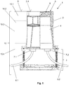
- Figure 1 shows a connection housing device 1 with a connection housing 2 and a stand 3.
- the connection housing 2 delimits a housing interior 4, which is accessible from above through an opening 5.
- the opening 5 is closed with a cover 6, which can be removed upwards.
- connection housing 2 is equipped with two connection points 7.1.7.2.
- an empty pipe 8.1 is inserted into the connection point 7.1 and then extends from an empty pipe string to the connection housing 2.
- an empty connection pipe 8.2 is inserted into the connection point 7.2, which then connects the connection housing 2 to the distributor / user, for example a building.
- connection housing 2 is placed outside the building in the layer structure 10 of the street 15 (see also Fig. 2 ), so that an upper edge 2.1 of the connection housing 2 is flush with an upper edge 9 of the layer structure 10, which is sketched in the left half of the picture.
- An upper layer 10.1 can, for example, be the paving layer (sidewalk) or asphalt surface layer (road), the layer 10.2 below can accordingly be a bed or a binder layer.
- the layers 10.3, 10.4 below represent base layers. If the connection housing 2 is positioned, the position of the upper edge 9 is already known (fixed), even if the layer structure 10 is sometimes only created significantly later.
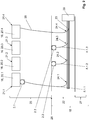
- Figure 2 illustrates various options for an application in the inventory.
- a street is opened up by laying fiber optics.
- buildings 20.1-20.4 are shown schematically as data user locations 16, each standing on a building floor area 21.1-21.4.
- the walkway 22 is broken open and a trench is dug, this is not shown in detail in the schematic top view.
- An empty pipe run 23 is laid in the trench, for each building 20.1-20.4 there is a respective data cable junction 24.1-24.4.
- the respective plots 25 extend, in between there is the property boundary 26.
- the carriageway 27 runs, which like the walkway 22 is part of the street 15.
- connection housing 2.1-2.3 For the buildings 20.1-20.3, for which (for the time being) no connection is desired, a connection housing 2.1-2.3 is placed. Furthermore, because the trench is currently dug, a respective empty pipe 8.1.1-8.1.3 is laid between the respective data cable junction 24.1-24.3 and the respective connection housing 2.1-2.3, cf. also the synopsis with Figure 1 for illustration. The trench can then be filled up and the layer structure 10 can be restored.
- the walkway 22 no longer has to be dug up.
- a data cable can be blown through the corresponding empty pipe 8.1.1-8.1.3 via the respective data cable junction 24.1-24.3 from a node 29, the cover 6 of the connection housing 2 can be opened and the data cable can be received there.
- the junction box 2.1 is located directly on the building floor area 21.1, and not in the main area, not in the area of the street, but on the property 25. When placed directly on the building, it no longer has to be dug up, but only drilled through the building's outer wall. In buildings 20.2, 20.3, a piece of land 25 must be excavated for laying the ground, but the effort for this is significantly less than for digging up the walkway 22.
- connection housings 2.2, 2.3 Due to their positioning in the layer structure 10 of the street 15, the connection housings 2.2, 2.3 are kept stable, they cannot sag or tilt. This can prevent the empty pipes 8.1,8.2 from slipping out and thus kinking the data cable.
- the connection housing 2.1 is not provided in the layer structure 10 of the street 15, but is stabilized due to the positioning directly on the building 20.1.
- FIGs 3a , b illustrate in a representation analog Figure 1 how a data cable 30 is laid through the empty pipe 8.1 into the housing interior 4. This takes place with an excess length, an end section 30. 1 of the data cable 30 has a length of approximately 10 m, taken away from an entry point 31 into the housing interior 4.
- Figure 3b illustrates how this end section 30.1 is then further routed to the data user or distribution point 16 through the previously or subsequently attached empty conduit 8.2, ie in the case of Fig. 2 to the building.
- the end 30.2 of the data cable 30 is pushed into the empty pipe 8.2, in the fully installed state it is then inside the building.
- connection housing 2.1-2.3 Advanced up to the connection housing 2
- connection housing 2.1-2.3 are produced in the same operation in which the connection is also made through the empty pipe 28.
- a data cable 30 would then be advanced into each of the connection housings 2.1-2.3, the corresponding end section 30.1 preferably being stored in a loop shape (risk of breakage).
- the connection housings 2.1-2.3 are actually already equipped with data cables 30 during the pre-routing.
- the positioning and connection via the empty pipes 8.1.1-8.1.3 alone is sufficient in that the sidewalk no longer has to be dug up.
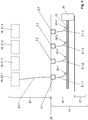
- Figure 4 illustrates an application in a new development area.
- the sidewalk 22 and the carriageway 27 of the street 15 are again drawn in for orientation, although these have not yet been produced when the empty conduit line 23 is being laid. In this case, no buildings have been created (at least not yet completely), which is why only the building floor areas 21.1-21.4 are shown.
- connection housing 2.1-2.4 When laying the empty pipe section 23, a respective empty pipe 8.1.1-8.1.4 is laid to a respective connection housing 2.1-2.4 at each data cable junction 24.1-24.4. In this case, the connection housings 2.1-2.4 are placed on the property boundaries 26, but still on the walkway 22. As a result, the later construction work on the land 25 is not hindered.
- connection pipe 8.2.1 is laid between the connection housing 2.1 and this building.
- the data cable is then laid from the node 29 through the data cable junction 24.1 and the connection housing 2.1 into the building.
- the data cables are already laid to the other connection housings 2.2-2.4, where they can be analog Figure 3a be filed.
- the node 29 must advantageously only be handled once.
- Figure 5 illustrates an alternative to the procedure according to the Figures 3a , b , namely the establishment of the user / distributor, in particular building connection via a further data cable 50.
- This is connected in the connection housing 2 to the data cable 30, in the present case by plugging together in a plug housing 51.
- This has a sealed interior, in which the data cables are 30.50 put together.
- Each of the data cables 30, 50 enters the plug housing 51 in a sealed manner.
- the plug housing can have an access opening; a variant with two separate access openings 52.1, 52.2 can be preferred.
- Each opening 52.1, 52.2 is provided with its own closure, the opening 52.1 is opened for the insertion of the data cable 30, the opening 52.2 for the insertion of the data cable 50.
- connection housing 2 in turn being placed between a data cable branch point 24 and a data user or distribution point 16.
- the latter is a radio unit 60, namely a WLAN module.
- This is or is arranged to provide a public WLAN network in a lantern post 61 shown schematically here.
- connection housing 2 is placed in each case (not necessarily on each lamppost, for example every second one may also be sufficient for sufficient network coverage). If the data cables are then blown in later from the node 29, the data cables can be laid in a single operation in each connection housing 2, analogously to the above description (see “new construction”), the respective radio module 60 can then be connected gradually.
- the connection housing 2 can also be placed at lampposts 61 if they are not or should not be equipped with a radio module 60 for the time being. The connection housing 2 can significantly simplify subsequent retrofitting (no digging of the walkway 22).
- connection housing 2 analog Figure 5 be moved (plug connection), the variant according to the Figures 3a , b (Looping through an excess length).
- the connection housing 2 can be opened, for example, and a connection can then be drilled through a housing wall of the connection housing 2 and a base wall of the lamppost 61.
- the variant according to Figure 6 for example also with that according to Figure 2 can be combined when the road 15 is being developed, so that connection housing 2 can be placed both on the buildings 20.1-20.3 that are not connected for the time being and on lampposts 61 (or also traffic lights etc.).
Landscapes
- Laying Of Electric Cables Or Lines Outside (AREA)
Abstract
- mit der Öffnung (5) nach oben weisend;
- horizontal im Bereich einer Straße (15);
- auf einer vertikalen Höhe, die innerhalb einer fertigen Aufbauhöhe eines Schichtaufbaus (10) der Straße (15) liegt, wobei aber die Öffnung (5) und damit der Gehäuseinnenraum (4) von oben zugänglich bleibt;
bei welchem Verfahren ferner ein Datenkabel (30) oder ein Leerrohr (8.1) für ein Datenkabel (30) zwischen der Datenkabel-Verzweigungsstelle (24) und dem Anschlussgehäuse (2) verlegt wird, das also die Datenkabel-Verzweigungsstelle (24) mit dem Anschlussgehäuse (2) verbindet.
Description
- Die vorliegende Erfindung betrifft ein Verfahren zum Bereitstellen einer Datenkabelanbindung für eine Datennutzer- oder Verteilerstelle, insbesondere für ein Gebäude.
- Der vorliegende Gegenstand richtet sich speziell auf das letzte Teilstück eines Datenkabelnetzes, nämlich die Anbindung des Nutzers/Verteilers bzw. Gebäudes an eine Datenkabel-Verzweigungsstelle. Bei dieser kann es sich insbesondere um einen Abzweig aus einem Strang handeln, der bspw. entlang einer Straße im Boden verläuft.
- Der vorliegenden Erfindung liegt das technische Problem zugrunde, ein vorteilhaftes Verfahren zur Anbindung an eine Datenkabel-Verzweigungsstelle anzugeben.
- Dies wird erfindungsgemäß mit dem Verfahren gemäß Anspruch 1 gelöst. Das Datenkabel bzw. ein Leerrohr dafür wird dabei nicht direkt von der Datenkabel-Verzweigungsstelle zu dem Nutzer/Verteiler bzw. Gebäude verlegt, sondern in bzw. über ein Anschlussgehäuse. Dieses wird im Bereich der Straße platziert, also im Falle des Gebäudes jedenfalls außerhalb der Gebäudegrundfläche, je nach Baustadium bzw. Anwendung (Neubau/Bestand) außerhalb des bereits errichteten Gebäudes oder der Fläche, auf welcher das Gebäude später errichtet wird. Das Anschlussgehäuse weist eine Öffnung auf, über die ein Gehäuseinnenraum zugänglich ist. Es wird zwischen der Datenkabel-Verzweigungsstelle und dem Nutzer/Verteiler bzw. Gebäude platziert, und zwar
- mit der Öffnung nach oben weisend;
- horizontal im Bereich einer Straße;
- vertikal auf einer Höhe, die innerhalb einer fertigen Schichtaufbauhöhe der Straße liegt, wobei aber die Öffnung und damit der Gehäuseinnenraum von oben zugänglich bleibt.
- Wird dann später der Straßenaufbau erstellt, also die Trag- und Deckschicht aufgebracht (z. B. Schotter aufgeschüttet, verdichtet und asphaltiert bzw. gepflastert), sitzt das Anschlussgehäuse in dem Schichtaufbau der Straße. Die Öffnung ist gleichwohl noch von oben ohne Entfernen der Deckschicht zugänglich, sie kann also im Wesentlichen bündig mit einer Oberkante des fertigen Schichtaufbaus liegen, bspw. der Deckschicht aus Asphalt oder Pflaster bzw. Platten.
- Mit dem Platzieren und Anschließen des Anschlussgehäuses an die Datenkabel-Verzweigungsstelle wird ein Zugangspunkt geschaffen, der das weitere Anschließen bzw. Erschließen der Datennutzer-/Verteilerstelle vereinfachen kann. Alternativ zu einem Gebäude (Büro- oder Wohngebäude) kann es sich hierbei bspw. auch um eine Antennenstation bzw. -einheit handeln (z. B. für öffentliches WLAN), siehe unten im Detail. Zur Veranschaulichung werden die Vorteile des Erfindungsgegenstands zunächst anhand der Erschließung eines Gebäudes diskutiert.
- Dabei können sich je nach Anwendung (Neubau/Bestand) unterschiedliche Vorteile ergeben, was im Folgenden illustriert wird. Der Gegenstand richtet sich insbesondere auf eine Glasfaser-Erschließung, bevorzugt ist bzw. sind also die Datenkabel Glasfaserkabel.
- Wird die Datenanbindung im Bestand nachgerüstet, kann die Netzverlegung typischerweise für ganze Straßenzüge bzw. Orts- oder Stadtteile erfolgen. Es wird dann die Straße, bspw. der Gehweg, aufgegraben und z. B. ein Kabelstrang verlegt, von dem bei jedem anzuschließenden Haushalt ein Kabel abgezweigt wird (an einer jeweiligen Datenkabel-Verzweigungsstelle). Der straßenseitige Graben wird dann wieder verfüllt und die zuvor aufgebrochene Deckschicht wird wiederhergestellt.
- Die Erfinder haben festgestellt, dass sich hierbei jedoch meist nur der kleinere Teil der Anwohner bzw. Eigentümer für eine Nachrüstung sofort entscheidet (typischerweise 1/3). Weitere Anschlüsse werden dann erst später, nach und nach angefragt. Hierfür muss dann jeweils erneut aufgegraben, also insbesondere die Deckschicht aufgebrochen und ein Abzweig zu dem jeweiligen Gebäude verlegt werden, was erheblichen Aufwand bedeutet. Es muss ferner bei jeder Nachbelegung der Bodenaufbau dann auch wiederhergestellt werden (insbesondere die Deckschicht/der Belag).
- Demgegenüber bietet das erfindungsgemäße Vorgehen die Möglichkeit, bei den vorerst noch nicht angeschlossenen Gebäuden jeweils ein Anschlussgehäuse zu setzen. Es kann dann entweder sogar bereits das Datenkabel bis in das Anschlussgehäuse verlegt und dort (vorerst) verwahrt werden, oder es kann das Anschlussgehäuse zumindest über das Leerrohr angebunden sein. Soll das Gebäude dann später (nach der eigentlichen Erschließung des Straßenzugs) doch noch angeschlossen werden, muss je nach Position des Anschlussgehäuses zumindest nicht der Gehweg/die Straße aufgegraben werden, mitunter ist auch gar kein Aufgraben notwendig (wenn das Anschlussgehäuse direkt am Gebäude sitzt, siehe unten im Detail).
- Auch wenn das Datenkabel nicht gleich bis in das Anschlussgehäuse vorverlegt wird, sondern dieses zunächst nur über das Leerrohr an die Datenkabel-Verzweigungsstelle angebunden ist, kann ein nachträgliches Anschließen des Gebäudes deutlich vereinfacht sein. Durch das Leerrohr kann dann nämlich das Datenkabel nachträglich eingeschoben bzw. -blasen werden, was bevorzugt von der Datenkabel-Verzweigungsstelle bzw. über diese erfolgt.
- Das erfindungsgemäße Vorgehen ist jedoch nicht nur bei einer Erschließung im Bestand, sondern auch im Neubau von Vorteil. In einem Neubaugebiet mag es zwar auf den ersten Blick weniger aufwendig und kostengünstiger erscheinen, die einzelnen Gebäude bzw. Gebäudegrundflächen jeweils direkt anzuschließen, also das Datenkabel bzw. Leerrohr dafür von der Datenkabel-Verzweigungsstelle direkt bis zum Gebäude bzw. dessen Grundfläche zu verlegen. Die Erfinder haben jedoch festgestellt, dass der Baufortschritt auf den einzelnen Grundstücken in der Praxis erheblich divergieren kann, sodass einige Gebäude bspw. schon bezogen werden, während sich andere noch im Rohbaustadium befinden, wenn überhaupt. Der Netzbetreiber kann deshalb nicht in einem Zug das gesamte Gebiet erschlie-ßen, sondern wiederum nur nach und nach.
- Das erfindungsgemäße Vorgehen eröffnet auch hier eine Möglichkeit der Vorverlegung, bspw. bis an das jeweilige Grundstück. Die Anschlussgehäuse können, wo später die Straße, insbesondere der Gehweg verläuft, bspw. an den Grundstückgrenzen platziert werden. Unabhängig von ihrer Position im Einzelnen kann der Netzbetreiber die einzelnen Datenkabel (für die einzelnen Gebäude bzw. Gebäudegrundflächen) dann in einem Zug bis in die Anschlussgehäuse verlegen, also in einem Arbeitsdurchgang (innerhalb eines Arbeitstages oder mehrerer zusammenhängender). Dieses Vorverlegen bis in die Anschlussgehäuse kann bspw. erfolgen, sobald der erste Haushalt seinen Datenanschluss erhält. Benötigen dann nach und nach die übrigen Haushalte ihren Datenanschluss, ist der Aufwand für die Verlegung dieser letzten Meter deutlich geringer als das Verlegen von der Datenkabel-Verzweigungsstelle aus bzw. über diese. Letzteres erfordert nämlich in der Regel mindestens zwei Techniker, die letzten Meter können auch von einem einzelnen Techniker verlegt werden.
- Generell werden die Datenkabel bevorzugt von einem Knotenpunkt aus verlegt, an dem mehrere, also die einzelnen Datenkabelverzweigungsstellen zusammenlaufen. Von diesem Knotenpunkt kann sich, wie vorstehend geschildert, ein Kabel- bzw. Leerrohrstrang entlang der Straße erstrecken (im Erdreich), wobei an den Gebäuden (bzw. allgemein Nutzern/Verteilern) jeweils ein Kabel/Leerrohr abgeht. An dem übergeordneten Knotenpunkt kann bspw. ein Verteilerkasten (Spleißkasten) oder eine Spleißmuffe angeordnet sein. Zwischen dem Knotenpunkt und den einzelnen Gebäuden (Nutzern/Verteilern) kann eine gewisse Wegstrecke liegen, und die Datenkabel werden in der Regel mit einem Spezialwerkzeug in die Leerrohre eingeblasen und damit über entsprechend große Strecken vorgeschoben. In dieser Hinsicht kann das vorstehend geschilderte Vorgehen, also das Vorverlegen vorerst nicht benötigter Datenkabel in einem Arbeitsgang, insoweit von Vorteil sein, als dann das entsprechende Spezialwerkzeug (Einblasvorrichtung) nur einmal an dem Knotenpunkt bereitgestellt werden muss. Die Arbeiten am Knotenpunkt können auch hinsichtlich der Kabelverbindung/-verzweigung dort Spezialwerkzeug erfordern, bspw. einen Kabelspleißer im Falle der bevorzugten Glasfaserkabel. Auch dieser muss dann nur einmal samt entsprechend geschultem Personal bereitgestellt werden, jedenfalls am Knotenpunkt (mitunter auch generell, vgl. insbesondere die Variante "Stecker" unten).
- Im Falle des Gebäudes sitzt das straßenseitig angeordnete Anschlussgehäuse außerhalb der Gebäudegrundfläche, also außerhalb der von dem Gebäude eingenommenen Fläche inklusive der Wände, also der nach den Außenmaßen genommene Brutto-Grundfläche. Diese kann kleiner sein als die überbaute Fläche (Dachüberstand). Das Anschlussgehäuse wird zwar außerhalb der Grundfläche platziert, kann jedoch durchaus innerhalb der überbauten Fläche liegen, bspw. im Falle eines direkt an der Gebäudeaußenwand platzierten Anschlussgehäuses. Letzteres kommt insbesondere bei einer Nachrüstung im Bestand in Betracht. Andererseits kann jedoch auch ein gewisser Mindestabstand zur Gebäudegrundfläche bevorzugt sein.
- Aufgrund der Platzierung des Anschlussgehäuses auf der Straße (in anderen Worten: an den Straßenrand grenzend), insbesondere dem Gehweg, etwa an die Grundstücksgrenze grenzend, muss dann bei einer nachträglichen Belegung der Gehweg / die Straße nicht nochmals aufgegraben werden, es kann bspw. auf bzw. von dem Grundstück seitlich an das Anschlussgehäuse herangegraben werden. Generell meint die "horizontale" Positionierung des Anschlussgehäuses "im Bereich einer Straße", dass das Anschlussgehäuse mit dem Schichtaufbau der Straße vertikal fluchtend angeordnet ist. Ist die Straße fertiggestellt, sitzt das Anschlussgehäuse in dem Schichtaufbau der Straße (weil es zudem auf einer vertikalen Höhe innerhalb der fertigen Schichtaufbauhöhe platziert wird).
- Der "Schichtaufbau" umfasst insbesondere eine Tragschicht, wobei auch mehrere aufeinandergesetzte Tragschichten möglich sind. Das Baustoffgemisch der Tragschicht kann insbesondere Schotter umfassen, dieser wird verdichtet. Darauf kommt eine Deckschicht, bspw. Asphalt oder Platten bzw. Pflastersteine, im Allgemeinen ist jedoch bspw. auch eine ungebundene Deckschicht möglich (eine Schotterschicht im Falle eines Schotterwegs). Das Platzieren im Schichtaufbau der Straße ist bspw. insoweit von Vorteil, als diese Schicht(en) verdichtet ist bzw. sind, also eine gute mechanische Stabilität bieten. Dies ist im vorliegenden Zusammenhang von besonderer Bedeutung, weil die Datenkabel bzw. die vergleichsweise dünnen Leerrohre dafür relativ empfindlich sind. Die Rohre (aus Kunststoff) bzw. Datenkabel können leicht abknicken, wobei die Glasfasern brechen können und ihre Funktion verlieren. Würde man das Anschlussgehäuse nicht im definierten Schichtaufbau der Straße, sondern an beliebiger Stelle im Erdreich platzieren, kann es bei Setzungen im Erdreich zu einem Abknicken bzw. anderweitigen Beschädigung des Leerrohres/Datenkabels kommen. Der Schichtaufbau der Straße wird hingegen definiert verdichtet, was z. B. mit einem dynamischen Plattendruckgerät und/oder einer Rammsonde (Gleichmäßigkeit der Verdichtung) überprüft werden kann (bzw. im Straßenbau überprüft wird).
- Bei der Montage bzw. Herstellung des Schichtaufbaus der Straße wird dann also seitlich um das Anschlussgehäuse herum z. B. eine Schotterschicht verdichtet, etwa mit einer Rüttelplatte. Bevorzugt gibt es mehrere aufeinander gesetzte, also nacheinander hergestellte Schotterschichten, die jeweils um das Anschlussgehäuse herum verdichtet werden. Das Anschlussgehäuse ist dann, speziell nach Aufbringen der Deckschicht, definiert und stabil eingebaut. Auch mit Blick auf einen solchen Einbau hat das Anschlussgehäuse bevorzugt eine Wandstärke (Gehäusewanddicke) von mindestens 5 mm, 7 mm, bzw. 8 mm, mit möglichen (davon unabhängigen) Obergrenzen bei z. B. höchstens 25 mm, 20 mm bzw. 15 mm (eine entsprechende Wandstärke soll die Gehäusewand nicht nur punktuell, sondern großflächig haben, bspw. über mindestens 70 %, 80 % bzw. 90 % der Gehäusewandfläche, bevorzugt über 100 %). Damit kann insbesondere auch im Falle des bevorzugt aus Kunststoffmaterial vorgesehenen Anschlussgehäuses eine hinreichende Stabilität erreicht werden. Generell kann das Anschlussgehäuse auch aus Metall vorgesehen sein (z. B. Druckguss), bevorzugt ist ein Kunststoffmaterial (Hartkunststoff), z. B. Polyamid, insbesondere Glasfaser-verstärkt, oder ein Copolymer-Material.
- Aufgrund der erforderlichen Abstimmung mit den Tiefbau-/Straßenbauunternehmen etc. mag die Positionierung im Straßenbereich zwar zunächst nachteilig erscheinen, in der Gesamtschau überwiegen jedoch die technischen Vorteile. Der Begriff "Straße" umfasst hierbei sowohl die Fahrbahn als auch den Gehweg, weitere Bestandteile können ein Radweg und auch Mittel- bzw. Seitenstreifen (Überland/Autobahn) sein. Prinzipiell kann das Anschlussgehäuse in jedem der genannten Bereiche platziert werden (im Bereich der Fahrbahn oder des Radwegs oder des Mittel-/Seitenstreifens oder des Gehwegs), bevorzugt ist bei einer üblichen Bebauung im örtlichen/städtischen Bereich eine Positionierung im Bereich des Gehwegs, besonders bevorzugt an der Grundstücksgrenze (am Straßenrand).
- Das Anschlussgehäuse kann dabei auch direkt an die Gebäudegrundfläche grenzend platziert werden, wenn bspw. im städtischen Bereich die Außenwand direkt am Gehweg liegt. Es kann es aber andererseits zwischen Gebäudegrundfläche und Anschlussgehäuse auch einen Mindestabstand von mindestens 1 m, 2 m bzw. 3 m geben. Mögliche Obergrenzen, die im Einzelnen auch von der Grundstücksgröße abhängen, können bspw. bei höchstens 50 m, 40 m, 30 m, 20 m, 15 m bzw. 10 m liegen.
- Wie bereits erwähnt, wird das Anschlussgehäuse auf einer Höhe innerhalb der fertigen Schichtaufbauhöhe der Straße platziert. Dies meint nicht, dass zur Erfüllung des hauptanspruchsgemäßen Gegenstands dann auch noch der Schichtaufbau erstellt werden muss (was in der Praxis in der Regel von anderen Arbeitern und mitunter auch erst deutlich später vorgenommen wird). Ist der Schichtaufbau dann fertig erstellt, sitzt das Anschlussgehäuse jedoch innerhalb davon. Bevorzugt liegt eine Oberkante des Anschlussgehäuses im Wesentlichen bündig mit der Oberkante des Schichtaufbaus (deren Lage ist vorab bekannt), also mit der Oberkante der Deckschicht. "Im Wesentlichen bündig" meint bspw. einen Versatz um weniger als 3 cm, 2 cm bzw. 1 cm. Im Rahmen der technisch üblichen Genauigkeit ist ein bündiger Einbau bevorzugt (0 cm). Das Anschlussgehäuse reicht bevorzugt in die Tragschicht bzw. -schichten hinein, erstreckt sich also bspw. mindestens über eine Höhe von 20 cm, 25 cm bzw. 30 cm (mit einer möglichen Obergrenze bei höchstens 50 cm, siehe unten im Detail).
- Die Öffnung des Anschlussgehäuses liegt oberseitig, bevorzugt ist sie mit einem reversibel herausnehm- und wiedereinsetzbaren Deckel verschlossen. Der Deckel kann sich bevorzugt ein Stück weit in die Öffnung hineinerstrecken, was einen sicheren Sitz gewährleisten kann. Es kann insbesondere ein verschließbarer Deckel vorgesehen sein, um einem unbefugten Zugang zu dem Gehäuseinneren vorzubeugen. Der Deckel lässt sich dann also nur mit einem speziellen Schlüssel öffnen. Das Anschlussgehäuse kann, von dem Deckel abgesehen, für sich einstückig sein; es kann aber auch mehrteilig vorgesehen sein, insbesondere in ein Ober- und ein Unterteil unterteilt sein. Diese Teile können zur Höhenpassung vertikal zueinander verschiebbar sein, also teleskopartig eine gewisse Anpassung der vertikalen Erstreckung des Anschlussgehäuses ermöglichen.
- Mit Blick auf die bevorzugten Glasfaserkabel, die bestimmte minimale Biegeradien haben (Bruchgefahr), kann eine Öffnung mit gewissen Mindestmaßen bevorzugt sein. Eine mittlere Öffnungsweite, die sich als Mittelwert der größten und kleinsten horizontalen Erstreckung der Öffnung ergibt und im bevorzugten Fall der Kreisform dem Kreisdurchmesser entspricht, kann bspw. bei mindestens 5 cm liegen, weiter und besonders bevorzugt mindestens 10 cm bzw. 12 cm. Mögliche Obergrenzen können (davon unabhängig) bspw. bei höchstens 40 cm bzw. 30 cm liegen. Der Deckel ist dann der Öffnung entsprechend bemessen.
- Wie vorstehend dargelegt, können sich vielfältige Vorteile ergeben, wenn die "Datennutzer- oder -verteilerstelle" ein Gebäude ist, bspw. ein Büro- oder Wohngebäude, wobei sowohl ein Mehrfamilienhaus als auch insbesondere ein Einfamilienhaus infrage kommt. Wie eingangs erwähnt, kann es sich bei der "Datennutzer-bzw. -verteilerstelle" jedoch auch um eine Antennenstation bzw. -einheit handeln, bspw. für öffentliches WLAN. Eine solche Antenneneinheit kann für sich (freistehend) vorgesehen sein, sie kann aber bspw. auch Teil einer Straßenlaterne oder Ampel sein (angesetzt oder auch baulich integriert).
- Im fertig montierten Zustand ist die Antenneneinheit dann mittels des Datenkabels über die Datenkabel-Verzweigungsstelle mit dem Knotenpunkt verbunden, über das Datenkabel werden Daten zu und auch von der Antenneneinheit übertragen, diese setzt das drahtgebundene Signal in ein Funksignal um. Dies kann auch ein Mobilfunksignal sein, es kann sich bei der Datennutzer- oder -verteilerstelle also bspw. auch um eine Mobilfunkstation handeln (z. B. für 5G). Eine solche Datennutzer- bzw. -verteilerstelle kann auch ein Technikgebäude umfassen, durch welches das Datenkabel geführt wird. Das Anschlussgehäuse wird dann außerhalb dieses Technikgebäudes im Bereich der Straße platziert, vgl. die vorstehenden Anmerkungen.
- Prinzipiell können sich bei der Anwendung "Antenneneinheit bzw. -station" dieselben Vorteile ergeben, wie vorstehend anhand der Gebäude geschildert. Wird bspw. ein Ortsteil bzw. Straßenzug erschlossen (die Straße aufgegraben und ein Leerrohrstrang verlegt, vgl. im Detail die vorstehenden Anmerkungen zum "Bestand"), ist nicht nur für die Büro-/Wohngebäude eine Vorverlegung möglich, sondern bspw. auch zur Errichtung eines öffentlichen WLAN-Netzes. Dazu kann ein jeweiliges Anschlussgehäuse bspw. an, also neben einer Laterne platziert werden, bevorzugt direkt neben dem Laternenpfosten bzw. einem Sockel. Die Laterne kann dann später für die Antenneneinheit eine Halterungsfunktion übernehmen, zudem ist dort auch Stromanschluss verfügbar (für den Umsetzer bzw. Konverter). Durch ein entsprechendes Platzieren von Anschlussgehäusen entlang der Straße, bspw. bei jeder oder jeder n-ten Laterne, kann ein Aufbau eines solchen WLAN-Netzes veranlagt werden. Es muss dann später nicht nochmals gesondert aufgegraben werden, vgl. die vorstehenden Anmerkungen. Auch wenn der Aufbau des WLAN-Netzes bereits beschlossen ist, können die bei den Laternen platzierten Anschlussgehäuse das Prozedere vereinfachen. Analog der vorstehenden Schilderung können die Datenkabel nämlich in einem Arbeitsgang vom Knotenpunkt zu den einzelnen Anschlussgehäusen verlegt werden, die eigentliche Montage an den einzelnen Laternen kann dann nach und nach erfolgen.
- Bevorzugte Ausgestaltungen finden sich in der vorliegenden Beschreibung, inklusive der Figuren, und den abhängigen Ansprüchen. In der Darstellung der Merkmale wird dabei nicht immer im Einzelnen zwischen Verfahrens- bzw. Verwendungs- oder Vorrichtungsaspekten unterschieden, jedenfalls implizit bezieht sich die Offenbarung auf sämtliche Anspruchskategorien. Wird also bspw. ein für einen bestimmten Einbau geeignetes Anschlussgehäuse beschrieben, ist dies auch als Offenbarung einer entsprechenden Verwendung bzw. des entsprechenden Verfahrens zu lesen (und umgekehrt).
- Hauptanspruchsgemäß wird zwischen der Datenkabelverzweigungsstelle und dem Anschlussgehäuse das Datenkabel selbst oder ein Leerrohr für dieses verlegt. Wird das Datenkabel selbst verlegt, das in dem Anschlussgehäuse dann zeitweilig in Schleifenform abgelegt werden kann (bis das entsprechende Gebäude bzw. der Nutzer/Verteiler tatsächlich angeschlossen wird, siehe vorne), könnte es im Prinzip auch direkt ins Erdreich gelegt werden. Bevorzugt wird jedoch auch in diesem Fall ein Leerrohr verlegt und das Datenkabel eingeschoben (eingeblasen, siehe vorne).
- In bevorzugter Ausgestaltung wird also zwischen der Datenkabel-Verzweigungsstelle und dem Anschlussgehäuse ein Leerrohr verlegt, das dann als Option zunächst unbelegt bleiben oder gleich zum Verlegen des Datenkabels genutzt werden kann. Das Leerrohr kann bspw. einen Außendurchmesser von höchstens 30 mm, 25 mm, 20 mm bzw. 15 mm haben (eine mögliche Untergrenze kann bspw. bei mindestens 7 mm bzw. 10 mm liegen). Bei einer Wandstärke von 1-2 mm steht ein Innenquerschnitt zur Verfügung, in dem das Datenkabel gut geführt ist.
- Generell wird das Leerrohr auf einer Höhe innerhalb der fertigen Schichtaufbauhöhe der Straße bzw. des Bodens verlegt, also unterhalb der Oberkante der fertigen Deckschicht (Pflaster/Platten bzw. Asphalt). Es kann bspw. mindestens 10 cm, 20 cm, 30 cm bzw. 40 cm unterhalb letzterer verlaufen, mit möglichen Obergrenzen bei höchstens 1,5 m, 1,2 m bzw. 1 m. Bevorzugt liegt das Leerrohr über die gesamte Strecke zwischen Datenkabel-Verzweigungsstelle und Anschlussgehäuse im Erdreich, also unterhalb der Oberkante des Schichtaufbaus.
- Wie bereits erwähnt, wird das Datenkabel, wenn das Leerrohr belegt wird, in bevorzugter Ausgestaltung mit einer Überlänge in das Anschlussgehäuse verlegt. Im fertig in das Anschlussgehäuse verlegten Zustand soll dann ein Endabschnitt des Datenkabels eine Länge von mindestens 1 m haben, wobei mindestens 2 m, 3 m, 4 m, 5 m, 6 m, 7 m, 8 m, 9 m bzw. 10 m weitere bevorzugte Untergrenzen sind. Mögliche Obergrenzen können bspw. höchstens 30 m, 20 m bzw. 15 m liegen. Konkret wird diese Länge zwischen der Eintrittsstelle, an welcher das Datenkabel aus dem Leerrohr in das Gehäuseinnere eintritt, bis zum Ende des Datenkabels genommen (dem Ende, das außerhalb des Leerrohres liegt, das also in einer Richtung von der Datenkabel-Verzweigungsstelle zu dem Anschlussgehäuse liegt).
- Bei einer bevorzugten Ausführungsform kann die Überlänge, also der Endabschnitt, dann vorübergehend in dem Anschlussgehäuse, also im Gehäuseinneren abgelegt werden. Dazu wird der Endabschnitt bevorzugt in Schleifenform gebracht, womit sich zuverlässig minimale Biegeradien nicht unterschreiten lassen. Es kann bspw. eine Kassette vorgesehen sein, also eine Ablagefläche mit Stegen bzw. Haken darauf, deren Abstand zueinander die Größe der Schleifenform vorgibt. Eine entsprechende Halterung für die Schleife kann bspw. direkt an der Gehäuseinnenwand bzw. als anderweitig integraler Teil des Gehäuses selbst vorgesehen sein, die Kassette kann aber auch herausnehm- und wiedereinsetzbar vorgesehen sein. Das Anschlussgehäuse kann dann bspw. eine Aufnahme zum Einhängen bzw. -schieben oder -clipsen der Kassette aufweisen.
- Bevorzugt wird die Öffnung des Anschlussgehäuses nach dem schleifenförmigen Ablegen des Endabschnitts verschlossen, wird also der Deckel auf- bzw. eingesetzt. Wird das Datenkabel nur kurzzeitig abgelegt und bspw. noch am selben Arbeitstag weiter zum Gebäude bzw. Nutzer/Verteiler verlegt, kann auch ein schleifenförmiges Ablegen ohne Verschließen des Deckels Vorteile bieten, kann das Datenkabel nämlich in dem Gehäuseinneren etwas geschützt sein.
- Die Verlegung zwischen Anschlussgehäuse und Gebäude bzw. Nutzer/Verteiler erfolgt bevorzugt ebenfalls im Erdreich, besonders bevorzugt wird hierfür zunächst wiederum ein Leerrohr (Anschluss-Leerrohr) verlegt, durch welches dann das Datenkabel geschoben werden kann. Im Zuge einer Nachbelegung muss hierfür zwar nochmals ausgegraben werden, allerdings nur auf dem Grundstück, nicht im öffentlichen Raum (Gehweg/Straße), was einen entsprechend geringeren Aufwand bedeutet. Das Anschlussgehäuse wird im Falle eines Gebäudes nämlich bevorzugt direkt an die Grundstücksgrenze gesetzt.
- Das Datenkabel bzw. der Endabschnitt wird bevorzugt derart von dem Anschlussgehäuse zum Gebäude verlegt, dass das Ende des Endabschnitts dann im Gebäude liegt. Dort liegt also der Abschlusspunkt der Linientechnik. In diesem Fall erstreckt sich das Datenkabel dann unterbrechungsfrei von diesem im Gebäudeinneren über das Anschlussgehäuse zu der Datenkabel-Verzweigungsstelle (in der Regel über diese hinaus bis zu einem Knotenpunkt). "Unterbrechungsfrei" meint insoweit ohne Verbindungstelle dazwischen (insbesondere ohne Spleißstelle). Dieses Vorgehen kann bspw. insoweit von Vorteil sein, als dann in dem Anschlussgehäuse keine "komplexeren" Arbeiten am Datenkabel erforderlich sind, also bspw. kein Spleißgerät zu dem Anschlussgehäuse geschafft werden muss. Zudem kann das Datenkabel in dem Anschlussgehäuse etwas "exponiert" gegenüber Umwelteinflüssen sein, weswegen ein unterbrechungsfreier Verlauf dort vorteilhaft sein kann.
- Bei einer alternativ bevorzugten Ausführungsform wird das Anschlussgehäuse genutzt, um dort eine Verbindungsstelle herzustellen. Das Datenkabel, das sich von der Datenkabel-Verzweigungsstelle bis in das Anschlussgehäuse erstreckt, kann dort ebenfalls eine gewisse Überlänge haben, bspw. von mindestens 0,5 m, 1 m bzw. 1,5 m, was das Arbeiten vereinfachen kann. Die Überlänge wird dann jedoch typischerweise geringer als im vorherigen Beispiel sein, sie kann z. B. höchstens 5 m, 4 m, 3 m bzw. 2 m betragen.
- Wird das Gebäude bzw. der Nutzer/Verteiler tatsächlich angeschlossen, wird dann zwischen dem Gebäude (Nutzer/Verteiler) und dem Anschlussgehäuse ein weiteres Datenkabel verlegt, bevorzugt in einem Anschluss-Leerrohr (vgl. insofern die vorstehenden Anmerkungen). Dieses weitere Datenkabel wird dann mit dem Datenkabel (das von der Datenkabel-Verzweigungsstelle kommt) verbunden, was im Allgemeinen bspw. auch durch Spleißen erfolgen kann. "Verbinden" ist in diesem Zusammenhang auf das Herstellen einer funktionalen Verbindungsstelle zu lesen, über welche hinweg Daten übertragbar sind. Allgemein können die vorliegend in Rede stehenden Daten insbesondere Internetdaten sein, was auch Telekommunikationsdaten wie E-Mail etc. und Telefonie (VOIP) umfasst, ebenso auch Fernseh- bzw. allgemein Unterhaltungsdaten. Wie verschiedentlich erwähnt, ist das Datenkabel bevorzugt ein Glasfaserkabel, welches eine einzige oder bevorzugt mehrere Glasfasern aufweisen kann. Beim Verbinden wird im Falle mehrerer Glasfasern dann jeweils eine Glasfaser des einen Datenkabels mit einer Glasfaser des anderen Datenkabels verbunden.
- Bei einer bevorzugten Ausführungsform ist zum Verbinden des Datenkabels, das von bzw. über die Datenkabel-Verzweigungsstelle kommt, und jenem für den Gebäudeanschluss ein Stecker vorgesehen. Das erstgenannte Datenkabel kann dann bspw. vom Netzbetreiber verlegt werden, bevorzugt zunächst ohne Stecker, was das Einschieben/Einblasen vereinfacht bzw. ermöglicht. Das Datenkabel wird dann also ohne Stecker am Ende durch das Leerrohr verlegt, bevorzugt über die Datenkabel-Verzweigungsstelle in Richtung des Anschlussgehäuses (insbesondere durch Einblasen von einem Knotenpunkt aus, siehe vorne). Anschließend wird das in das Anschlussgehäuse verlegte Ende für die Steckverbindung vorbereitet, wird also bspw. ein Stecker angespleißt.
- Das weitere Datenkabel, das zwischen Anschlussgehäuse und Nutzer/Verteiler bzw. Gebäude verlegt wird, ist bevorzugt an einem oder auch beiden Enden mit einem Stecker bzw. Aufsatz zum Ansetzen eines Steckers vorkonfektioniert. An einem vorkonfektionierten Ende lässt sich der Stecker dann ohne besonderes Spezialwerkzeug, insbesondere ohne Spleißgerät, zusammensetzen, exemplarisch wird auf die
EP 2 482 109 A2 bzw. das Produkt DiaLink von Diamond verwiesen. Das vorkonfektionierte Ende lässt sich ohne das angesetzte Steckerteil gut durch das Anschluss-Leerrohr verlegen, danach wird das Steckerteil aufgesetzt und kann die Steckverbindung mit dem Datenkabel hergestellt werden (dies ist bspw. der Ablauf beim Einschieben des weiteren Datenkabels vom Gebäudeinneren her). Das weitere Datenkabel kann jedoch auch vom Anschlussgehäuse her eingeschoben werden, das Ende mit dem abnehm- und aufsetzbaren Steckerteil wird dann also ins Gebäudeinnere geschoben und dort zusammengesetzt. Das in dem Anschlussgehäuse angeordnete Ende kann in diesem Fall auch mit einem fertigen Stecker ausgestattet sein. - Gemäß einer bevorzugten Ausführungsform ist in dem Anschlussgehäuse ein wasserdichtes Steckergehäuse angeordnet. Zur Vereinfachung der Installation kann dieses herausnehm- und wiedereinsetzbar sein, kann also in dem Anschlussgehäuse eine entsprechende Aufnahme vorgesehen sein. Das Anschlussgehäuse kann auch für unterschiedliche Anwendungen ausgelegt sein, es kann also sowohl mit einem Steckergehäuse als auch mit einer Kassette zum Aufnehmen eines schleifenförmig abgelegten Datenkabels ausgestattet sein. Je nach Einsatz kann dann die eine oder die andere Möglichkeit genutzt werden.
- In dem wasserdichten Steckergehäuse sind Datenkabel-Stecker abgedichtet zusammensteckbar. Bevorzugt weist es einen nach außen abgedichteten Innenraum auf, in dem die Datenkabel-Stecker zusammengesteckt werden können. In dem Gehäuse kann es für jedes der Datenkabel eine Durchdringungs- bzw. Einrittsstelle geben, die bspw. jeweils mit einem Dichteinsatz ausgestattet einen wasserdichten Eintritt des Kabels in den Innenraum gewährleisten kann.
- Besonders bevorzugt kann ein in mindestens zwei Kammern unterteilter Innenraum sein, wobei die Kammern von außen über jeweils einen eigenen Verschluss zugänglich sind. Durch Öffnen des einen Verschlusses kann eine Kammer geöffnet und z. B. das Datenkabel eingesteckt werden, durch Öffnen des anderen Verschlusses kann die andere Kammer geöffnet und das weitere Datenkabel eingesteckt werden. Der bzw. die Verschlüsse können danach wieder verschlossen werden. Mit den separaten Kammern kann insbesondere auch dann, wenn die Datenkabel mit einem Zeitversatz verlegt werden, festgelegt sein, in wessen Verantwortungsbereich jeweils welche Vorgänge liegen. Nach dem Verlegen des Datenkabels bzw. weiteren Datenkabels wird jeweils die entsprechende Öffnung verschlossen. Wird bspw. beim Verlegen des weiteren Datenkabels die entsprechende Öffnung nicht richtig verschlossen, lässt sich dieser Montagefehler eindeutig zuordnen.
- Das Anschlussgehäuse (nicht das Steckergehäuse) ist in bevorzugter Ausgestaltung nicht wasserdicht, sondern unterseitig mit einer oder mehreren Öffnungen ausgestattet. Durch diese kann von oben eingelaufenes oder eingesickertes Wasser dann wieder nach unten ablaufen. Im Allgemeinen kann das Anschlussgehäuse hingegen selbstverständlich auch wasserdicht gestaltet sein, kann also der Gehäuseinnenraum bei auf- bzw. eingesetztem Deckel ein abgeschlossenes Volumen darstellen. Die Handhabung bzw. fachgerechte Montage eines solchen Anschlussgehäuses ist jedoch mitunter schwieriger und aufwendiger, und bei Montagefehlern kann schließlich doch Wasser eindringen, das dann nicht ablaufen kann (sondern im Gehäuseinnenraum steht).
- Für das Leerrohr gibt es bevorzugt eine gedichtete Anschlussstelle am Gehäuse (gedichtet gegen das Leerrohr). Dazu kann die Anschlussstelle ein Dichtelement aufweisen, an welches das Leerrohr angesetzt wird, bevorzugt wird das Leerrohr eingeschoben. Prinzipiell ist auch ein alleiniges Einschieben des Leerrohres denkbar, einem Steckfitting vergleichbar. Bevorzugt wird nach dem Einschieben des Leerrohres eine Überwurfmutter auf- bzw. festgeschraubt, die dann bspw. mit bzw. über eine Schrägfläche das Dichtelement andrücken kann. Unabhängig von der technischen Umsetzung im Einzelnen ist also ein Fitting (Schraub- und/oder Steckfitting) zum Ansetzen des Leerrohres in das Anschlussgehäuse integriert, insbesondere an bzw. in eine Außenwand davon gesetzt. Bevorzugt weist das Anschlussgehäuse eine weitere Anschlussstelle auf, nämlich für das Anschluss-Leerrohr, bevorzugt sind die Anschlussstellen dann identisch aufgebaut. Generell ist bzw. sind die Anschlussstelle(n) baulich am Anschlussgehäuse festgelegt, schaffen sie also für das bzw. die Leerrohre einen räumlichen Fixpunkt am Anschlussgehäuse, also einer Außenwand davon (einer Seitenwand oder bevorzugt Bodenwand, siehe unten). Das jeweilige Leerrohr ist damit auszugsicher am Anschlussgehäuse gehalten, was einem Abknicken bzw. anderweitigen Beschädigung des Leerrohres (und damit des Datenkabels) vorbeugen hilft.
- In bevorzugter Ausgestaltung wird das Leerrohr und/oder das Gebäudeanschluss-Leerrohr zum Gehäuseinneren hin gedichtet. Ist durch das entsprechende Leerrohr ein Datenkabel verlegt, kann bspw. ein Dichtelement mit einer entsprechenden Durchlassöffnung vorgesehen sein (dieses dichtet gegen das Kabel und gegen das Leerrohr). Ist noch kein Datenkabel verlegt, kann das Leerrohr mit einem Blindstopfen bzw. -verschluss verschlossen sein. Das Abdichten der Leerrohre kann bspw. einem Wassereintritt (zum Gebäude oder Knotenpunkt hin) vorbeugen oder auch eine Barriere für Schleichgas darstellen. Speziell in Verbindung mit der vorstehend geschilderten "Auszugsicherung" kann das Abdichten die Sicherheit erhöhen, weil damit einem Verrutschen bzw. -setzen des Leerrohres vorgebeugt wird, bei dem sich die Abdichtung des Leerrohres lösen könnte. Besonders bevorzugt kann eine Integration der Leerrohr-Abdichtung in die Anschlussstelle sein, wird dort also das Leerrohr angesetzt und gehalten, sowie zugleich gedichtet (nicht bzw. nicht nur an der Außenwandfläche, sondern auch der Innenraum).
- Bei einer bevorzugten Ausführungsform weist das Anschlussgehäuse eine Führungsvorrichtung auf, um ein von der Datenkabel-Verzweigungsstelle her eingeschobenes Datenkabel nach oben durch die Öffnung aus dem Anschlussgehäuse herauszuführen. Diese Führungsvorrichtung schließt an die Eintrittsstelle an, an welcher das Datenkabel ins Gehäuseinnere gelangt. Sie ist bevorzugt in ihrer Position am Anschlussgehäuse festgelegt, bspw. angeformt oder befestigt. Sie ist bevorzugt an der Anschlussstelle befestigt an welche gehäuseaußenseitig das Leerrohr gesetzt ist. Die Führungsvorrichtung kann einen Kanal begrenzen, in dem das Ende des Datenkabels beim Einschieben ins Gehäuseinnere nach oben geführt wird. Dieser Kanal kann im Allgemeinen auch offen sein, bspw. eine U-bzw. V-Form haben, er kann jedoch auch von einem kurzen Rohrstück gebildet sein. Als Führungsvorrichtung kann im Allgemeinen auch ein Leitblech oder dergleichen vorgesehen sein, funktional soll das Ende des Datenkabels entlang der Führungsvorrichtung nach oben gelenkt werden. Die Führungsvorrichtung kann damit einem Verfangen des Datenkabels im Gehäuseinneren bzw. Öffnungsrand etc. vorbeugen, also eine Beschädigung vermeiden helfen.
- Wie bereits erwähnt, liegt die Datenkabel-Verzweigungsstelle bevorzugt an einem Leerrohrstrang, bildet sie nämlich einen Abzweig davon. Der Leerrohrstrang erstreckt sich entlang mehrerer Nutzer- bzw. Verteilerstellen. Im Falle der Gebäude erstreckt er sich entlang mehrerer Gebäudegrundflächen, die bereits bebaut sein können (Bestand) oder bebaut werden (Neubaugebiet). Ein Abstand zwischen Datenkabel-Verzweigungsstelle und Anschlussgehäuse kann bspw. höchstens 15 m, 10 m, 5 m bzw. 3 m betragen, mögliche Untergrenzen können (davon unabhängig) bei z. B. mindestens 0,5 m bzw. 1 m liegen.
- Im Bestand kann bei der Erschließung dann bei einem oder auch mehreren der Gebäude direkt ein Leerrohr von der jeweiligen Datenkabel-Verzweigungsstelle zum Gebäude verlegt werden, also ohne Anschlussgehäuse dazwischen. So kann für jene Haushalte bzw. Eigentümer vorgegangen werden, die sich bereits bei der Erschließung für einen entsprechenden Datenanschluss entscheiden. Bei jenen Gebäuden, für die (vorerst) kein Datenanschluss gewünscht ist, wird jeweils ein Anschlussgehäuse platziert (und über ein Leerrohr von der Datenkabel-Verzweigungsstelle angeschlossen). Prinzipiell könnten dabei mehrere Gebäude auch über ein gemeinsames Anschlussgehäuse zusammengefasst werden, bevorzugt wird jedem Gebäude ein eigenes Anschlussgehäuse zugeordnet. Bezüglich der Möglichkeiten zur Platzierung des Anschlussgehäuses (direkt an der Gebäudegrundfläche oder an der Grundstücksgrenze etc.) wird auf die vorstehenden Ausführungen verwiesen, gleiches gilt für die Möglichkeiten der Vorbereitung der Nachbelegung (Endabschnitt in Schleifenform im Gehäuseinneren vorgehalten, Stecker oder auch vorerst nur Leerrohranbindung).
- Im Neubaugebiet werden bevorzugt sämtliche Anschlüsse über ein Anschlussgehäuse geführt, bevorzugt ist für jedes Gebäude ein eigenes Anschlussgehäuse vorgesehen. Mit Blick auf die noch folgenden Bauarbeiten wird dieses dann bevorzugt an der Grundstücksgrenze platziert. Auch hier kommen prinzipiell sämtliche vorstehend diskutierten Verlegetechniken (zwischen Anschlussgehäuse und dem dann errichteten Gebäude) in Betracht, im Anschlussgehäuse kann dann der Endabschnitt schleifenförmig abgelegt werden oder die Anbindung über einen Stecker vorbereitet werden. Von dem Knotenpunkt aus können die einzelnen Datenkabel jedenfalls in einem Arbeitsvorgang verlegt werden.
- Offenbart sein soll auch ein Verfahren zum Bereitstellen einer Datenkabelanbindung für ein Gebäude (vgl. die vorst. Definitionen), und zwar einer Anbindung an eine Datenkabel-Verzweigungsstelle (vgl. die vorst. Definitionen), wobei ein Anschlussgehäuse vorgesehen wird, das einen Gehäuseinnenraum aufweist, der von außen über eine Öffnung in dem Anschlussgehäuse zugänglich ist, wobei das Anschlussgehäuse zwischen der Datenkabel-Verzweigungsstelle und dem Gebäude positioniert wird, und zwar außerhalb einer Gebäudegrundfläche (vgl. die vorst. Definitionen), dabei aber nahe an der Gebäudegrundfläche, bspw. in einem Abstand von höchstens 1 m, bevorzugt direkt daran grenzend, wobei das Anschlussgehäuse auf einer vertikalen Höhe platziert wird, die innerhalb der fertigen Bodenaufbauhöhe liegt, wobei aber die Öffnung von oben zugänglich bleibt. Bevorzugt wird das Anschlussgehäuse so platziert, dass es an eine Außenwandfläche einer Kelleraußenwand des Gebäudes grenzt.
- Im Unterschied zu der bzw. den vorstehend diskutierten Varianten ist bzw. wird das Anschlussgehäuse in diesem Fall nicht zwingend im Bereich der Straße, also im Schichtaufbau der Straße angeordnet. Eine Positionierung im Schichtaufbau der Straße ist zwar möglich (z. B. in der Stadt, Gebäudeaußenwand/Fassade direkt am Gehweg), aber nicht zwingend. Das Anschlussgehäuse kann bspw. auch auf einem Grundstück im Boden, also im Erdreich verlegt werden. Dabei könnte sich zwar prinzipiell die vorstehend geschilderte Setzungsproblematik ergeben, die Positionierung an der Gebäudegrundfläche schafft jedoch eine Stabilisierung, die Kelleraußenwand kann also abstützend wirken (dort stützt sich einerseits das Anschlussgehäuse selbst ab, andererseits ist auch das Erdreich etwas stabilisiert (zur Seite hin).
- Die Positionierung an der Gebäudegrundfläche kann bspw. auch insoweit von Vorteil sein, als die Verbindung zwischen Anschlussgehäuse und Gebäude dann auch ganz ohne Aufgraben hergestellt werden kann. Durch die Gebäudeaußenwand kann gebohrt werden, durch diese Bohrung lässt sich das Datenkabel bzw. weitere Datenkabel (siehe vorne) dann ins Gebäude verlegen. Die Bohrung kann bspw. oberirdisch in die Gebäudeaußenwand eingebracht werden, etwa im Falle eines kellerlosen Gebäudes, oder im Falle eines unterkellerten Gebäudes auch unterirdisch, also in die Kelleraußenwand. Zu einer oberirdischen Bohrung kann das (weitere) Datenkabel bspw. in einem Kabelschacht entlang der Außenwandfläche geführt werden, die unterirdische Bohrung kann sich bevorzugt direkt in das Anschlussgehäuse erstrecken.
- Die Erfindung betrifft auch eine Anschlussgehäusevorrichtung, die in einem vorliegend geschilderten Verfahren Anwendung finden kann. Diese weist zum einen das Anschlussgehäuse und zum anderen einen Ständer auf, der das Anschlussgehäuse trägt. Wird also der Ständer im Erdreich auf dem Boden platziert, ist das Anschlussgehäuse damit etwas angehoben. Es ist insbesondere eine Unterseite zugänglich, also ein Unterboden des Anschlussgehäuses, dort sitzt bzw. sitzen dann die Anschlussstelle(n) für das/die Leerrohr(e).
- Das bzw. die Leerrohre werden also von unten an/in das Anschlussgehäuse geführt. Geht man bspw. von einer Verlegetiefe von rund 60 cm aus, kann das Anschlussgehäuse dementsprechend eine in Höhenrichtung kompaktere Bauform haben, bspw. von höchstens 50 cm, bevorzugt höchstens 40 cm. Eine mögliche Mindesthöhe des Anschlussgehäuses kann bspw. bei mindestens 15 cm, 20 cm bzw. 25 cm liegen. Die unterseitige Anordnung der Anschlussstellen erlaubt also einerseits eine gewisse Mindesttiefe der Verlegung (Frostsicherheit etc.), andererseits wird das Anschlussgehäuse insgesamt nicht zu groß, was hinsichtlich der Material- bzw. Transportkosten und auch die Handhabung betreffend von Vorteil sein kann.
- Die Erfindung betrifft auch eine Verwendung, bei welcher ein Anschlussgehäuse in einer vorstehend diskutierten Weise platziert wird (horizontal im Bereich der Straße, vertikal auf einer Höhe innerhalb der fertigen Aufbauhöhe des Schichtaufbaus der Straße) und dann der Schichtaufbau der Straße hergestellt wird, vgl. auch die vorstehenden Anmerkungen. Teil der Verwendung kann insbesondere auch das anschließende Öffnen des Deckels sein (zu Montagezwecken), danach kann die Öffnung wieder verschlossen werden (mit dem Deckel).
- Im Folgenden wird die Erfindung anhand eines Ausführungsbeispiels näher erläutert, wobei die einzelnen Merkmale im Rahmen der nebengeordneten Ansprüche auch in anderer Kombination erfindungswesentlich sein können und auch weiterhin nicht im Einzelnen zwischen den unterschiedlichen Anspruchskategorien unterschieden wird.
- Im Einzelnen zeigt
- Figur 1
- eine Anschlussgehäusevorrichtung mit einem Anschlussgehäuse zur Durchführung eines erfindungsgemäßen Verfahrens in einer teilweise geschnittenen Seitenansicht;
- Figur 2
- verschiedene Möglichkeiten zur Positionierung von Anschlussgehäusen bei einer Erschließung von Gebäuden im Bestand;
- Figur 3a,b
- eine erste Möglichkeit zur Weiterverlegung zwischen Anschlussgehäuse und Gebäude bzw. Verteiler/Nutzer;
- Figur 4
- analog
Figur 2 eine Möglichkeit zur Positionierung von Anschlussgegehäusen im Falle eines Neubaugebiets; - Figur 5
- eine zweite Möglichkeit zur Weiterverlegung zwischen Anschlussgehäuse und Gebäude bzw. Verteiler/Nutzer;
- Figur 6
- eine WLAN-Einheit für öffentliches WLAN als Nutzer/Verteiler.
-
Figur 1 zeigt eine Anschlussgehäusevorrichtung 1 mit einem Anschlussgehäuse 2 und einem Ständer 3. Das Anschlussgehäuse 2 begrenzt einen Gehäuseinnenraum 4, dieser ist von oben durch eine Öffnung 5 zugänglich. Die Öffnung 5 ist vorliegend mit einem Deckel 6 verschlossen, der nach oben herausgenommen werden kann. - Unterseitig ist das Anschlussgehäuse 2 mit zwei Anschlussstellen 7.1,7.2 ausgestattet. Wie nachstehend im Einzelnen diskutiert, wird in die Anschlussstelle 7.1 ein Leerrohr 8.1 eingeschoben, dass sich dann von einem Leerrohrstrang zu dem Anschlussgehäuse 2 erstreckt. In die Anschlussstelle 7.2 wird, je nach Anwendung und Vorgehen im Einzelnen, ein Anschluss-Leerrohr 8.2 eingeschoben, welches dann das Anschlussgehäuse 2 mit dem Verteiler/Nutzer, bspw. einem Gebäude verbindet.
- Das Anschlussgehäuse 2 wird außerhalb des Gebäudes im Schichtaufbau 10 der Straße 15 platziert (siehe auch
Fig. 2 ), sodass also eine Oberkante 2.1 des Anschlussgehäuses 2 bündig mit einer Oberkante 9 des Schichtaufbaus 10 liegt, der in der linken Bildhälfte skizziert ist. Eine obere Schicht 10.1 kann bspw. die Pflasterschicht (Gehweg) oder Asphaltdeckschicht (Straße) sein, die Schicht 10.2 darunter kann entsprechend ein Bett oder eine Binderschicht sein. Die darunterliegenden Schichten 10.3,10.4 stellen Tragschichten dar. Wird das Anschlussgehäuse 2 positioniert, ist die Lage der Oberkante 9 bereits bekannt (festgelegt), auch wenn der Schichtaufbau 10 mitunter erst deutlich später erstellt wird. -
Figur 2 illustriert verschiedene Möglichkeiten bei einer Anwendung im Bestand. In der hier dargestellten Situation wird ein Straßenzug durch Glasfaserverlegung erschlossen. Schematisch sind als Datennutzerstellen 16 vier Gebäude 20.1-20.4 dargestellt, die jeweils auf einer Gebäudegrundfläche 21.1-21.4 stehen. Für die Erschließung wird der Gehweg 22 aufgebrochen und wird ein Graben ausgehoben, dieser ist in der schematischen Aufsicht nicht im Einzelnen dargestellt. In dem Graben wird ein Leerrohrstrang 23 verlegt, für jedes Gebäude 20.1-20.4 gibt es eine jeweilige Datenkabel-Verzweigungsstelle 24.1-24.4. Zur Illustration und Orientierung: in der Darstellung oberhalb des Gehwegs 22 erstrecken sich die jeweiligen Grundstücke 25, dazwischen liegt jeweils die Grundstücksgrenze 26. In der Darstellung unterhalb des Gehwegs 22 verläuft die Fahrbahn 27, die wie der Gehweg 22 Teil der Straße 15 ist. - Im Zuge der Erschließung dieses Straßenzugs hat sich hier exemplarisch nur ein Eigentümer für einen sofortigen Anschluss entschlossen, dies ist das Gebäude 20.4. In diesem Fall kann von der Datenkabel-Verzweigungsstelle 24.4 zu dem Gebäude 20.4 direkt ein Leerrohr 28 verlegt werden. Durch dieses wird dann das Datenkabel verlegt.
- Für die Gebäude 20.1-20.3, für die (vorerst) kein Anschluss gewünscht ist, wird jeweils ein Anschlussgehäuse 2.1-2.3 platziert. Ferner wird, weil ja der Graben momentan ausgehoben ist, ein jeweiliges Leerrohr 8.1.1-8.1.3 zwischen der jeweiligen Datenkabel-Verzweigungsstelle 24.1-24.3 und dem jeweiligen Anschlussgehäuse 2.1-2.3 verlegt, vgl. auch die Zusammenschau mit
Figur 1 zur Illustration. Der Graben kann dann aufgeschüttet, und es kann der Schichtaufbau 10 wiederhergestellt werden. - Soll dann später zu einem der Gebäude 20.1-20.3 doch ein Datenkabel verlegt werden, muss jedenfalls der Gehweg 22 nicht mehr aufgegraben werden. Durch das entsprechende Leerrohr 8.1.1-8.1.3 kann über die jeweilige Datenkabel-Verzweigungsstelle 24.1-24.3 von einem Knotenpunkt 29 aus ein Datenkabel eingeblasen werden, es kann der Deckel 6 des Anschlussgehäuses 2 geöffnet und das Datenkabel dort entgegengenommen werden. Bei dem Gebäude 20.1 sitzt das Anschlussgehäuse 2.1 direkt an der Gebäudegrundfläche 21.1, und zwar nicht hauptanspruchsgemäß nicht im Bereich der Straße, sondern auf dem Grundstück 25. Bei der Platzierung direkt am Gebäude muss gar nicht mehr aufgegraben, sondern nur durch die Gebäudeaußenwand gebohrt werden. Bei den Gebäuden 20.2,20.3 muss zur Erdverlegung zwar ein Stück auf dem Grundstück 25 ausgehoben werden, der Aufwand hierfür ist jedoch deutlich geringer als für das Aufgraben des Gehwegs 22.
- Aufgrund ihrer Positionierung im Schichtaufbau 10 der Straße 15 sind die Anschlussgehäuse 2.2,2.3 stabil gehalten, sie können nicht absacken bzw. verkippen. Damit kann einem Herausrutschen der Leerrohre 8.1,8.2 und damit einem Abknicken des Datenkabels vorgebeugt werden. Ein einfach in die Erde gesetztes, also nicht in Tragschichten 10.3,10.4 eingefasstes Anschlussgehäuse 2 wäre hingegen instabil, speziell Glasfaserkabel wären bruchgefährdet. Das Anschlussgehäuse 2.1 ist zwar nicht im Schichtaufbau 10 der Straße 15 vorgesehen, jedoch aufgrund der Positionierung direkt am Gebäude 20.1 stabilisiert.
- Die
Figuren 3a ,b illustrieren in einer Darstellung analogFigur 1 , wie ein Datenkabel 30 durch das Leerrohr 8.1 in das Gehäuseinnere 4 verlegt wird. Dies erfolgt mit einer Überlänge, ein Endabschnitt 30.1 des Datenkabels 30 hat von einer Eintrittsstelle 31 in das Gehäuseinnere 4 weg genommen eine Länge von rund 10 m.Figur 3b illustriert, wie dieser Endabschnitt 30.1 dann durch das vorab oder nachträglich angesetzte Anschluss-Leerrohr 8.2 weiter zur Datennutzer- bzw. - verteilerstelle 16 verlegt, also im Falle vonFig. 2 zum Gebäude. Konkret wird das Ende 30.2 des Datenkabels 30 in das Leerrohr 8.2 eingeschoben, im fertig installierten Zustand liegt es dann innerhalb des Gebäudes. - Der Zustand gemäß
Figur 3a (Vorverlegung bis in das Anschlussgehäuse 2) kann in der Situation gemäßFigur 2 für die Anschlussgehäuse 2.1-2.3 im selben Arbeitsvorgang hergestellt werden, in dem auch der Anschluss durch das Leerrohr 28 gelegt wird. Es wäre dann also in jedes der Anschlussgehäuse 2.1-2.3 ein Datenkabel 30 vorverlegt, wobei der entsprechende Endabschnitt 30.1 bevorzugt in Schleifenform (Bruchgefahr) abgelegt wird. Zusammengefasst gibt es also einerseits die Möglichkeit, dass die Anschlussgehäuse 2.1-2.3 bei der Vorverlegung bereits tatsächlich mit Datenkabeln 30 bestückt werden. Andererseits ist jedoch auch allein die Positionierung und Anbindung über die Leerrohre 8.1.1-8.1.3 dahingehend ausreichend, dass der Gehweg nicht mehr aufgegraben werden muss. -
Figur 4 illustriert eine Anwendung in einem Neubaugebiet. Zur Orientierung sind wiederum der Gehweg 22 und die Fahrbahn 27 der Straße 15 eingezeichnet, wobei diese bei der Verlegung des Leerrohrstranges 23 noch gar nicht hergestellt sind. In diesem Fall sind auch noch keine Gebäude erstellt (jedenfalls noch nicht vollständig), weswegen nur die Gebäudegrundflächen 21.1-21.4 eingezeichnet sind. - Bei der Verlegung des Leerrohrstranges 23 wird an jeder Datenkabel-Verzweigungsstelle 24.1-24.4 ein jeweiliges Leerrohr 8.1.1-8.1.4 zu einem jeweiligen Anschlussgehäuse 2.1-2.4 verlegt. Die Anschlussgehäuse 2.1-2.4 werden in diesem Fall an den Grundstücksgrenzen 26, aber noch auf dem Gehweg 22 platziert. Dadurch werden die späteren Bauarbeiten auf den Grundstücken 25 nicht behindert.
- Wird dann das erste Gebäude fertiggestellt, bspw. auf der Gebäudegrundfläche 21.1, wird zwischen dem Anschlussgehäuse 2.1 und diesem Gebäude ein Anschluss-Leerrohr 8.2.1 verlegt. Von dem Knotenpunkt 29 her wird dann das Datenkabel über die Datenkabel-Verzweigungsstelle 24.1 und das Anschlussgehäuse 2.1 bis in das Gebäude verlegt. In diesem Zuge werden dann auch zu den anderen Anschlussgehäusen 2.2-2.4 bereits die Datenkabel verlegt, sie können dort analog
Figur 3a abgelegt werden. Es muss dann vorteilhafterweise nur einmal an dem Knotenpunkt 29 hantiert werden. -
Figur 5 illustriert eine Alternative zu dem Vorgehen gemäß denFiguren 3a ,b , nämlich die Herstellung der Nutzer/Verteiler-, insbesondere Gebäudeanbindung über ein weiteres Datenkabel 50. Dieses wird in dem Anschlussgehäuse 2 mit dem Datenkabel 30 verbunden, vorliegend durch Zusammenstecken in einem Steckergehäuse 51. Dieses weist einen abgedichteten Innenraum auf, in diesem werden die Datenkabel 30,50 zusammengesteckt. Jedes der Datenkabel 30,50 tritt gedichtet in das Steckergehäuse 51 ein. Das Steckergehäuse kann prinzipiell eine Zugangsöffnung haben, bevorzugt kann eine Variante mit zwei separaten Zugangsöffnungen 52.1,52.2 sein. Jede Öffnung 52.1,52.2 ist mit einem eigenen Verschluss versehen, die Öffnung 52.1 wird zum Einbringen des Datenkabels 30 geöffnet, die Öffnung 52.2 zum Einbringen des Datenkabels 50. -
Figur 6 zeigt eine weitere Anwendungsmöglichkeit, wobei das Anschlussgehäuse 2 wiederum zwischen einer Datenkabel-Verzweigungsstelle 24 und einer Datennutzer- oder -verteilerstelle 16 platziert wird. Konkret handelt es sich bei letzterer um eine Funkeinheit 60, nämlich ein WLAN-Modul. Dieses ist bzw. wird zur Bereitstellung eines öffentlichen WLAN-Netzes in einem hier schematisch gezeigten Laternenpfosten 61 angeordnet. Bei der Erschließung des Straßenzugs, also wenn der Gehweg 22 aufgegraben ist und der Leerrohrstrang 23 verlegt wird, wird das Anschlussgehäuse 2 neben dem Laternenpfosten 61 platziert und über das Leerrohr 8.1 mit der Datenkabel-Verzweigungsstelle 24 verbunden. - Bei den übrigen, entlang der Straße 15 angeordneten (nicht dargestellten) Laternenpfosten wird in analoger Weise verfahren, wird also jeweils ein Anschlussgehäuse 2 platziert (nicht zwingend an jedem Laternenpfosten, es kann bspw. auch jeder zweite für eine hinreichende Netzabdeckung ausreichend sein). Werden dann später die Datenkabel von dem Knotenpunkt 29 her eingeblasen, können die Datenkabel analog der vorstehenden Schilderung (siehe "Neubau") in einem Arbeitsgang in jedes Anschlussgehäuse 2 verlegt werden, die Anbindung des jeweiligen Funkmoduls 60 kann dann nach und nach erfolgen. Die Anschlussgehäuse 2 lassen sich auch bei Laternenpfosten 61 platzieren, wenn diese vorerst noch gar nicht mit einem Funkmodul 60 ausgestattet sind bzw. werden sollen. Das Anschlussgehäuse 2 kann eine spätere Nachrüstung deutlich vereinfachen (kein Aufgraben des Gehwegs 22).
- Bei der Variante gemäß
Figur 6 kann in dem Anschlussgehäuse 2 analogFigur 5 verfahren werden (Steckverbindung), bevorzugt ist die Variante gemäß denFiguren 3a ,b (Hindurchschleifen einer Überlänge). Das Anschlussgehäuse 2 kann hierfür bspw. geöffnet werden, und es kann dann eine Verbindung durch eine Gehäusewand des Anschlussgehäuses 2 und eine Sockelwand des Laternenpfostens 61 gebohrt werden. Selbstverständlich kann die Variante gemäßFigur 6 bspw. auch mit jener gemäßFigur 2 kombiniert werden, können bei der Erschließung der Straße 15 also sowohl an den vorerst nicht angeschlossenen Gebäuden 20.1-20.3 als auch an Laternenpfosten 61 (oder auch Ampeln etc.) Anschlussgehäuse 2 platziert werden.
Claims (16)
- Verfahren zum Bereitstellen einer Datenkabelanbindung für eine Datennutzer- oder -verteilerstelle (16), und zwar einer Anbindung an eine Datenkabel-Verzweigungsstelle (24),wozu ein Anschlussgehäuse (2) vorgesehen wird, das einen Gehäuseinnenraum (4) aufweist, der von außen über eine Öffnung (5) in dem Anschlussgehäuse (2) zugänglich ist, wobei das Anschlussgehäuse (2) zwischen der Datennutzer- oder -verteilerstelle (16) positioniert wird, und zwar- mit der Öffnung (5) nach oben weisend;- horizontal im Bereich einer Straße (15);- auf einer vertikalen Höhe, die innerhalb einer fertigen Aufbauhöhe eines Schichtaufbaus (10) der Straße (15) liegt, wobei aber die Öffnung (5) und damit der Gehäuseinnenraum (4) von oben zugänglich bleibt;bei welchem Verfahren ferner ein Datenkabel (30) oder ein Leerrohr (8.1) für ein Datenkabel (30) zwischen der Datenkabel-Verzweigungsstelle (24) und dem Anschlussgehäuse (2) verlegt wird, das also die Datenkabel-Verzweigungsstelle (24) mit dem Anschlussgehäuse (2) verbindet.
- Verfahren nach Anspruch 1, bei welchem in einem zwischen der Datenkabel-Verzweigungsstelle (24) und dem Anschlussgehäuse (2) verlegten Leerrohr (8.1) ein Datenkabel (30) verlegt wird, vorzugsweise in einer Richtung von der Datenkabel-Verzweigungsstelle (24) zu dem Anschlussgehäuse (2) eingeschoben wird.
- Verfahren nach Anspruch 1 oder 2, bei welchem das in das Anschlussgehäuse (2) verlegte Datenkabel (30) dort eine Überlänge hat, nämlich ein Endabschnitt (30.1) des verlegten Datenkabels (30) von einer Eintrittsstelle (31) in das Gehäuseinnere (4) weg genommen eine Länge von mindestens 1 m hat.
- Verfahren nach Anspruch 3, bei welchem der Endabschnitt (30.1) in dem Anschlussgehäuse (2) in Schleifenform abgelegt wird und danach die Öffnung (5) des Anschlussgehäuses (2) verschlossen wird.
- Verfahren nach Anspruch 3 oder 4, bei welchem die Öffnung (5) des Anschlussgehäuses (2) wieder geöffnet wird und der Endabschnitt (30.1) des Datenkabels (30) zu der Datennutzer- oder -verteilerstelle (16) verlegt wird, vorzugsweise in einem Anschluss-Leerrohr (8.2).
- Verfahren nach einem der Ansprüche 2 bis 4, bei welchem ein Endabschnitt (30.1) des Datenkabels (30), der sich in das Gehäuseinnere (4) erstreckt, mit einem weiteren Datenkabel (50) verbunden wird, das sich im verlegten Zustand von dem Anschlussgehäuse (2) zu der Datennutzer- oder - verteilerstelle (16) hin erstreckt.
- Verfahren nach Anspruch 6, bei welchem der Endabschnitt (30.1) des Datenkabels (30) mit einem Stecker versehen ist oder wird, über welchen das Datenkabel (30) mit dem weiteren Datenkabel (50) zusammengesteckt und dadurch verbunden wird.
- Verfahren nach einem der vorstehenden Ansprüche, bei welchem in dem Anschlussgehäuse (2) ein wasserdichtes Steckergehäuse (51) angeordnet ist, in dem Datenkabel-Stecker abgedichtet zusammensteckbar sind.
- Verfahren nach Anspruch 8, bei welchem die Datenkabel-Stecker in einem Innenraum des wasserdichten Steckergehäuses (51) zusammensteckbar sind, der in mindestens zwei Kammern unterteilt ist, die von außerhalb des Steckergehäuses (51) jeweils über eine eigene Zugangsöffnung (52.1,52.2) mit jeweils einem eigenen, offen- und wiederverschließbaren Verschluss zugänglich sind.
- Verfahren nach einem der vorstehenden Ansprüche, bei welchem das Anschlussgehäuse (2) eine Öffnung aufweist, durch welche in den Gehäuseinnenraum (4) eingelaufenes oder -gesickertes Wasser nach unten ablaufen kann.
- Verfahren nach einem der vorstehenden Ansprüche, bei welchem das Leerrohr (8.1) und/oder ein zusätzliches, an das Anschlussgehäuse (2) gesetztes Anschluss-Leerrohr auf einer Höhe innerhalb der fertigen Aufbauhöhe des Schichtaufbaus (10) verlegt wird, wobei zumindest eines der Leerrohre (8.1,8.2) zum Gehäuseinneren (4) hin gedichtet wird.
- Verfahren nach einem der vorstehenden Ansprüche, bei welchem das Anschlussgehäuse (2) eine Führungsvorrichtung aufweist, die dazu vorgesehen ist, ein in einer Richtung von der Datenkabel-Verzweigungsstelle (24) zu dem Anschlussgehäuse (2) durch das Leerrohr (8.1) eingeschobenes Datenkabel (31) nach oben durch die Öffnung (5) des Anschlussgehäuses (2) aus diesem herauszuführen.
- Verfahren nach einem der vorstehenden Ansprüche, bei welchem die Verzweigungsstelle (24) an einem Leerrohrstrang (23) liegt, der sich entlang mehrerer Datennutzer- oder -verteilerstellen (16) erstreckt, nämlich entlang mehrerer Gebäude (20.1-20.4) bzw. Gebäudegrundflächen (21.1-21.4), wobei jeder Gebäudegrundfläche (21) ein jeweiliges Anschlussgehäuse (2.1-2.4) zugeordnet wird, nämlich außerhalb der jeweiligen Gebäudegrundfläche (21.1-21.4) platziert wird, und wobei für jedes Anschlussgehäuse (2.1-2.4) zwischen einer jeweiligen Datenkabel-Verzweigungsstelle (24.1-24.4) an dem Leerrohrstrang (23) und dem jeweiligen Anschlussgehäuse (2.1-2.4) ein jeweiliges Leerrohr (8.1.1-8.1.4) für ein jeweiliges Datenkabel verlegt wird.
- Verfahren nach einem der Ansprüche 1 bis 12, bei welchem die Verzweigungsstelle (24) an einem Leerrohrstrang (23) liegt, der sich entlang mehrerer Datennutzer- oder -verteilerstellen (16) erstreckt, nämlich entlang mehrerer Gebäude (20.1-20.4), wobei zu einem Teil (20.4) der Gebäude (20) ein jeweiliges Leerrohr (28) direkt zwischen einer jeweiligen Datenkabel-Verzweigungsstelle (24.4) an dem Leerrohrstrang (23) und dem Gebäude (20.4) verlegt wird, und wobei bei einem anderen Teil (20.1-20.3) der Gebäude (20) ein jeweiliges Anschlussgehäuse (2.1-2.3) außerhalb der jeweiligen Gebäudegrundfläche (21.1-21.3) platziert wird und für jedes Anschlussgehäuse (2.1-2.3) zwischen einer jeweiligen Datenkabel-Verzweigungsstelle (24.1-24.3) an dem Leerrohrstrang (23) und dem jeweiligen Anschlussgehäuse (2.1-2.3) ein jeweiliges Leerrohr (8.1.1-8.1.3) für ein jeweiliges Datenkabel verlegt wird.
- Anschlussgehäusevorrichtung für ein Verfahren nach einem der vorstehenden Ansprüche,
welches ein Anschlussgehäuse (2) und
einen Ständer (3) aufweist, der das Anschlussgehäuse (2) trägt, also eine Unterseite des Anschlussgehäuses (2) anhebt,
wobei das Anschlussgehäuse (2) für sich eine Höhe von maximal 50 cm hat und an der Unterseits eine Anschlussstelle (7.1,7.2) zum Ansetzen eines Leerrohres hat. - Verwendung eines Anschlussgehäuses (2), bei welcher gemäß einem der Ansprüche 1 bis 14 das Anschlussgehäuse (2) positioniert und zwischen der Datenkabel-Verzweigungsstelle (24) und dem Anschlussgehäuse (2) das Datenkabel (30) oder das Leerrohr (8.1) für ein Datenkabel (30) verlegt wird, wobei dann ferner der Schichtaufbau (10) der Straße (15) hergestellt wird, innerhalb welchem das Anschlussgehäuse (2) dann sitzt, wobei die Öffnung (5) und damit der Gehäuseinnenraum (4) von oben zugänglich ist.
Priority Applications (6)
| Application Number | Priority Date | Filing Date | Title |
|---|---|---|---|
| PL18209245.2T PL3660990T3 (pl) | 2018-11-29 | 2018-11-29 | Sposób dostarczania połączenia kabla do przesyłu danych |
| EP18209245.2A EP3660990B1 (de) | 2018-11-29 | 2018-11-29 | Verfahren zum bereitstellen einer datenkabelanbindung |
| DE102019007483.1A DE102019007483A1 (de) | 2018-11-29 | 2019-10-28 | Anschlussgehäusevorrichtung |
| EP19205652.1A EP3660992A1 (de) | 2018-11-29 | 2019-10-28 | Anschlussgehäusevorrichtung |
| EP19205632.3A EP3660991B1 (de) | 2018-11-29 | 2019-10-28 | Anschlussgehäusevorrichtung |
| EP19205668.7A EP3660993A1 (de) | 2018-11-29 | 2019-10-28 | Anschlussgehäusevorrichtung |
Applications Claiming Priority (1)
| Application Number | Priority Date | Filing Date | Title |
|---|---|---|---|
| EP18209245.2A EP3660990B1 (de) | 2018-11-29 | 2018-11-29 | Verfahren zum bereitstellen einer datenkabelanbindung |
Publications (2)
| Publication Number | Publication Date |
|---|---|
| EP3660990A1 true EP3660990A1 (de) | 2020-06-03 |
| EP3660990B1 EP3660990B1 (de) | 2024-01-10 |
Family
ID=64572102
Family Applications (1)
| Application Number | Title | Priority Date | Filing Date |
|---|---|---|---|
| EP18209245.2A Active EP3660990B1 (de) | 2018-11-29 | 2018-11-29 | Verfahren zum bereitstellen einer datenkabelanbindung |
Country Status (2)
| Country | Link |
|---|---|
| EP (1) | EP3660990B1 (de) |
| PL (1) | PL3660990T3 (de) |
Cited By (3)
| Publication number | Priority date | Publication date | Assignee | Title |
|---|---|---|---|---|
| DE202020106773U1 (de) | 2020-11-25 | 2022-02-28 | Hexatronic Gmbh | Installationssystem mit einem Einführmechanismus |
| DE202020106772U1 (de) | 2020-11-25 | 2022-02-28 | Hexatronic Gmbh | Installationssystem |
| EP4047766A1 (de) * | 2021-02-22 | 2022-08-24 | Hauff-Technik GmbH & Co. KG | Gebäudeinstallationsanordnung |
Citations (8)
| Publication number | Priority date | Publication date | Assignee | Title |
|---|---|---|---|---|
| JPH04102803A (ja) * | 1990-08-22 | 1992-04-03 | Tokyo Met Gov Gesuidou Service Kk | 光通信路の布設工法 |
| GB2260034A (en) * | 1991-09-20 | 1993-03-31 | Ackermann Ltd | Underfloor cable distribution system |
| JPH06118253A (ja) * | 1992-10-03 | 1994-04-28 | Sumitomo Electric Ind Ltd | 光ファイバケーブルの直埋敷設方法及びピットボックス |
| JPH10290517A (ja) * | 1997-04-15 | 1998-10-27 | Haneda Hume Pipe Co Ltd | 通信ケーブル用マンホール |
| JPH10336847A (ja) * | 1997-05-27 | 1998-12-18 | Haneda Hume Pipe Co Ltd | 通信ケーブル用マンホール |
| US20010043839A1 (en) * | 1998-07-30 | 2001-11-22 | Martin Prusak | Method of laying data cables and the like in underground pipes and pipe-cable combinations |
| WO2009000004A1 (de) * | 2007-06-25 | 2008-12-31 | Cablerunner Austria Gmbh | Netzwerk und verfahren zur übertragung von daten in rohrleitungssystemen |
| EP2482109A2 (de) | 2011-01-28 | 2012-08-01 | Diamond SA | Zugbegrenzungselement für eine faseroptische Verbindung, sowie Patchcord und Pigtail mit diesem Zugbegrenzungselement |
Family Cites Families (1)
| Publication number | Priority date | Publication date | Assignee | Title |
|---|---|---|---|---|
| US8588571B1 (en) * | 2010-11-08 | 2013-11-19 | Google Inc. | Installation of fiber-to-the-premise using optical demarcation devices |
-
2018
- 2018-11-29 PL PL18209245.2T patent/PL3660990T3/pl unknown
- 2018-11-29 EP EP18209245.2A patent/EP3660990B1/de active Active
Patent Citations (8)
| Publication number | Priority date | Publication date | Assignee | Title |
|---|---|---|---|---|
| JPH04102803A (ja) * | 1990-08-22 | 1992-04-03 | Tokyo Met Gov Gesuidou Service Kk | 光通信路の布設工法 |
| GB2260034A (en) * | 1991-09-20 | 1993-03-31 | Ackermann Ltd | Underfloor cable distribution system |
| JPH06118253A (ja) * | 1992-10-03 | 1994-04-28 | Sumitomo Electric Ind Ltd | 光ファイバケーブルの直埋敷設方法及びピットボックス |
| JPH10290517A (ja) * | 1997-04-15 | 1998-10-27 | Haneda Hume Pipe Co Ltd | 通信ケーブル用マンホール |
| JPH10336847A (ja) * | 1997-05-27 | 1998-12-18 | Haneda Hume Pipe Co Ltd | 通信ケーブル用マンホール |
| US20010043839A1 (en) * | 1998-07-30 | 2001-11-22 | Martin Prusak | Method of laying data cables and the like in underground pipes and pipe-cable combinations |
| WO2009000004A1 (de) * | 2007-06-25 | 2008-12-31 | Cablerunner Austria Gmbh | Netzwerk und verfahren zur übertragung von daten in rohrleitungssystemen |
| EP2482109A2 (de) | 2011-01-28 | 2012-08-01 | Diamond SA | Zugbegrenzungselement für eine faseroptische Verbindung, sowie Patchcord und Pigtail mit diesem Zugbegrenzungselement |
Cited By (4)
| Publication number | Priority date | Publication date | Assignee | Title |
|---|---|---|---|---|
| DE202020106773U1 (de) | 2020-11-25 | 2022-02-28 | Hexatronic Gmbh | Installationssystem mit einem Einführmechanismus |
| DE202020106772U1 (de) | 2020-11-25 | 2022-02-28 | Hexatronic Gmbh | Installationssystem |
| EP4047766A1 (de) * | 2021-02-22 | 2022-08-24 | Hauff-Technik GmbH & Co. KG | Gebäudeinstallationsanordnung |
| EP4611195A3 (de) * | 2021-02-22 | 2025-10-29 | Hauff-Technik GmbH & Co. KG | Gebäudeinstallationsanordnung |
Also Published As
| Publication number | Publication date |
|---|---|
| EP3660990B1 (de) | 2024-01-10 |
| PL3660990T3 (pl) | 2024-05-13 |
Similar Documents
| Publication | Publication Date | Title |
|---|---|---|
| EP3660990B1 (de) | Verfahren zum bereitstellen einer datenkabelanbindung | |
| DE102008020847A1 (de) | Fundamentkörper, Verfahren zur Herstellung eines Fundamentkörpers sowie Verfahren zum Aufstellen eines Mastes | |
| DE202019001267U1 (de) | Anschlussgehäusevorrichtung | |
| EP4059101A1 (de) | Verwendung eines anschlussgehäuses | |
| EP3660991B1 (de) | Anschlussgehäusevorrichtung | |
| DE10023399B4 (de) | Erschließungs-, Revisions- und Verteilerschacht mit Hausanschluß-Winkelplatte | |
| DE202019002446U1 (de) | Anschlussgehäusevorrichtung | |
| DE10018432A1 (de) | Mehrfach-Kanalrohrsystem | |
| DE202018107162U1 (de) | Kabelschacht | |
| EP4148927B1 (de) | Verwendung einer gehäusevorrichtung | |
| DE10233981A1 (de) | Hausanschlussschacht | |
| EP4047766B1 (de) | Gebäudeinstallationsanordnung | |
| DE102005006240B4 (de) | Infrastrukturleerrohrsystem | |
| EP4175086A1 (de) | Verwendung eines leerrohrsystems | |
| DE102019133706A1 (de) | Verwendung zum Anbinden einer Datennutzer- oder Datenverteilerstelle | |
| EP4295454A1 (de) | Verfahren zum bereitstellen einer datenkabelanbindung | |
| EP1662051B1 (de) | Verfahren zum Verbinden eines öffentlichen Verteilerschachtes mit einem Hausanschluss | |
| DE202021004205U1 (de) | Gebäudeinstallationsanordnung | |
| DE202021004206U1 (de) | Gebäudeinstallationsanordnung | |
| DE102021104116A1 (de) | Gebäudeinstallationsanordnung | |
| DE202021004207U1 (de) | Gebäudeinstallationsanordnung | |
| EP3835841A1 (de) | Verwendung eines anschlussgehäuses | |
| DE1515669A1 (de) | Stadtnetz fuer Stromvesorgung und/oder Telefonie | |
| DE202014006416U1 (de) | Einzel - Hausanschluss - Box und Hausanschluß - Winkelplatte | |
| DE102020003258A1 (de) | Verwendung eines Anschlussgehäuses |
Legal Events
| Date | Code | Title | Description |
|---|---|---|---|
| PUAI | Public reference made under article 153(3) epc to a published international application that has entered the european phase |
Free format text: ORIGINAL CODE: 0009012 |
|
| STAA | Information on the status of an ep patent application or granted ep patent |
Free format text: STATUS: THE APPLICATION HAS BEEN PUBLISHED |
|
| AK | Designated contracting states |
Kind code of ref document: A1 Designated state(s): AL AT BE BG CH CY CZ DE DK EE ES FI FR GB GR HR HU IE IS IT LI LT LU LV MC MK MT NL NO PL PT RO RS SE SI SK SM TR |
|
| AX | Request for extension of the european patent |
Extension state: BA ME |
|
| STAA | Information on the status of an ep patent application or granted ep patent |
Free format text: STATUS: REQUEST FOR EXAMINATION WAS MADE |
|
| 17P | Request for examination filed |
Effective date: 20201201 |
|
| RBV | Designated contracting states (corrected) |
Designated state(s): AL AT BE BG CH CY CZ DE DK EE ES FI FR GB GR HR HU IE IS IT LI LT LU LV MC MK MT NL NO PL PT RO RS SE SI SK SM TR |
|
| STAA | Information on the status of an ep patent application or granted ep patent |
Free format text: STATUS: EXAMINATION IS IN PROGRESS |
|
| 17Q | First examination report despatched |
Effective date: 20210319 |
|
| GRAP | Despatch of communication of intention to grant a patent |
Free format text: ORIGINAL CODE: EPIDOSNIGR1 |
|
| STAA | Information on the status of an ep patent application or granted ep patent |
Free format text: STATUS: GRANT OF PATENT IS INTENDED |
|
| INTG | Intention to grant announced |
Effective date: 20230524 |
|
| GRAJ | Information related to disapproval of communication of intention to grant by the applicant or resumption of examination proceedings by the epo deleted |
Free format text: ORIGINAL CODE: EPIDOSDIGR1 |
|
| STAA | Information on the status of an ep patent application or granted ep patent |
Free format text: STATUS: EXAMINATION IS IN PROGRESS |
|
| GRAP | Despatch of communication of intention to grant a patent |
Free format text: ORIGINAL CODE: EPIDOSNIGR1 |
|
| STAA | Information on the status of an ep patent application or granted ep patent |
Free format text: STATUS: GRANT OF PATENT IS INTENDED |
|
| INTC | Intention to grant announced (deleted) | ||
| INTG | Intention to grant announced |
Effective date: 20230801 |
|
| GRAS | Grant fee paid |
Free format text: ORIGINAL CODE: EPIDOSNIGR3 |
|
| GRAA | (expected) grant |
Free format text: ORIGINAL CODE: 0009210 |
|
| STAA | Information on the status of an ep patent application or granted ep patent |
Free format text: STATUS: THE PATENT HAS BEEN GRANTED |
|
| AK | Designated contracting states |
Kind code of ref document: B1 Designated state(s): AL AT BE BG CH CY CZ DE DK EE ES FI FR GB GR HR HU IE IS IT LI LT LU LV MC MK MT NL NO PL PT RO RS SE SI SK SM TR |
|
| REG | Reference to a national code |
Ref country code: GB Ref legal event code: FG4D Free format text: NOT ENGLISH |
|
| REG | Reference to a national code |
Ref country code: CH Ref legal event code: EP |
|
| REG | Reference to a national code |
Ref country code: DE Ref legal event code: R096 Ref document number: 502018013945 Country of ref document: DE |
|
| REG | Reference to a national code |
Ref country code: IE Ref legal event code: FG4D Free format text: LANGUAGE OF EP DOCUMENT: GERMAN |
|
| P01 | Opt-out of the competence of the unified patent court (upc) registered |
Effective date: 20240108 |
|
| REG | Reference to a national code |
Ref country code: SE Ref legal event code: TRGR |
|
| REG | Reference to a national code |
Ref country code: NL Ref legal event code: FP |
|
| REG | Reference to a national code |
Ref country code: LT Ref legal event code: MG9D |
|
| PG25 | Lapsed in a contracting state [announced via postgrant information from national office to epo] |
Ref country code: IS Free format text: LAPSE BECAUSE OF FAILURE TO SUBMIT A TRANSLATION OF THE DESCRIPTION OR TO PAY THE FEE WITHIN THE PRESCRIBED TIME-LIMIT Effective date: 20240510 |
|
| PG25 | Lapsed in a contracting state [announced via postgrant information from national office to epo] |
Ref country code: LT Free format text: LAPSE BECAUSE OF FAILURE TO SUBMIT A TRANSLATION OF THE DESCRIPTION OR TO PAY THE FEE WITHIN THE PRESCRIBED TIME-LIMIT Effective date: 20240110 |
|
| PG25 | Lapsed in a contracting state [announced via postgrant information from national office to epo] |
Ref country code: GR Free format text: LAPSE BECAUSE OF FAILURE TO SUBMIT A TRANSLATION OF THE DESCRIPTION OR TO PAY THE FEE WITHIN THE PRESCRIBED TIME-LIMIT Effective date: 20240411 |
|
| PG25 | Lapsed in a contracting state [announced via postgrant information from national office to epo] |
Ref country code: RS Free format text: LAPSE BECAUSE OF FAILURE TO SUBMIT A TRANSLATION OF THE DESCRIPTION OR TO PAY THE FEE WITHIN THE PRESCRIBED TIME-LIMIT Effective date: 20240410 Ref country code: HR Free format text: LAPSE BECAUSE OF FAILURE TO SUBMIT A TRANSLATION OF THE DESCRIPTION OR TO PAY THE FEE WITHIN THE PRESCRIBED TIME-LIMIT Effective date: 20240110 |
|
| PG25 | Lapsed in a contracting state [announced via postgrant information from national office to epo] |
Ref country code: ES Free format text: LAPSE BECAUSE OF FAILURE TO SUBMIT A TRANSLATION OF THE DESCRIPTION OR TO PAY THE FEE WITHIN THE PRESCRIBED TIME-LIMIT Effective date: 20240110 |
|
| PG25 | Lapsed in a contracting state [announced via postgrant information from national office to epo] |
Ref country code: RS Free format text: LAPSE BECAUSE OF FAILURE TO SUBMIT A TRANSLATION OF THE DESCRIPTION OR TO PAY THE FEE WITHIN THE PRESCRIBED TIME-LIMIT Effective date: 20240410 Ref country code: NO Free format text: LAPSE BECAUSE OF FAILURE TO SUBMIT A TRANSLATION OF THE DESCRIPTION OR TO PAY THE FEE WITHIN THE PRESCRIBED TIME-LIMIT Effective date: 20240410 Ref country code: LT Free format text: LAPSE BECAUSE OF FAILURE TO SUBMIT A TRANSLATION OF THE DESCRIPTION OR TO PAY THE FEE WITHIN THE PRESCRIBED TIME-LIMIT Effective date: 20240110 Ref country code: IS Free format text: LAPSE BECAUSE OF FAILURE TO SUBMIT A TRANSLATION OF THE DESCRIPTION OR TO PAY THE FEE WITHIN THE PRESCRIBED TIME-LIMIT Effective date: 20240510 Ref country code: HR Free format text: LAPSE BECAUSE OF FAILURE TO SUBMIT A TRANSLATION OF THE DESCRIPTION OR TO PAY THE FEE WITHIN THE PRESCRIBED TIME-LIMIT Effective date: 20240110 Ref country code: GR Free format text: LAPSE BECAUSE OF FAILURE TO SUBMIT A TRANSLATION OF THE DESCRIPTION OR TO PAY THE FEE WITHIN THE PRESCRIBED TIME-LIMIT Effective date: 20240411 Ref country code: ES Free format text: LAPSE BECAUSE OF FAILURE TO SUBMIT A TRANSLATION OF THE DESCRIPTION OR TO PAY THE FEE WITHIN THE PRESCRIBED TIME-LIMIT Effective date: 20240110 Ref country code: BG Free format text: LAPSE BECAUSE OF FAILURE TO SUBMIT A TRANSLATION OF THE DESCRIPTION OR TO PAY THE FEE WITHIN THE PRESCRIBED TIME-LIMIT Effective date: 20240110 |
|
| PG25 | Lapsed in a contracting state [announced via postgrant information from national office to epo] |
Ref country code: PT Free format text: LAPSE BECAUSE OF FAILURE TO SUBMIT A TRANSLATION OF THE DESCRIPTION OR TO PAY THE FEE WITHIN THE PRESCRIBED TIME-LIMIT Effective date: 20240510 |
|
| PG25 | Lapsed in a contracting state [announced via postgrant information from national office to epo] |
Ref country code: PT Free format text: LAPSE BECAUSE OF FAILURE TO SUBMIT A TRANSLATION OF THE DESCRIPTION OR TO PAY THE FEE WITHIN THE PRESCRIBED TIME-LIMIT Effective date: 20240510 Ref country code: LV Free format text: LAPSE BECAUSE OF FAILURE TO SUBMIT A TRANSLATION OF THE DESCRIPTION OR TO PAY THE FEE WITHIN THE PRESCRIBED TIME-LIMIT Effective date: 20240110 |
|
| PG25 | Lapsed in a contracting state [announced via postgrant information from national office to epo] |
Ref country code: DK Free format text: LAPSE BECAUSE OF FAILURE TO SUBMIT A TRANSLATION OF THE DESCRIPTION OR TO PAY THE FEE WITHIN THE PRESCRIBED TIME-LIMIT Effective date: 20240110 |
|
| REG | Reference to a national code |
Ref country code: DE Ref legal event code: R097 Ref document number: 502018013945 Country of ref document: DE |
|
| PG25 | Lapsed in a contracting state [announced via postgrant information from national office to epo] |
Ref country code: SM Free format text: LAPSE BECAUSE OF FAILURE TO SUBMIT A TRANSLATION OF THE DESCRIPTION OR TO PAY THE FEE WITHIN THE PRESCRIBED TIME-LIMIT Effective date: 20240110 |
|
| PG25 | Lapsed in a contracting state [announced via postgrant information from national office to epo] |
Ref country code: EE Free format text: LAPSE BECAUSE OF FAILURE TO SUBMIT A TRANSLATION OF THE DESCRIPTION OR TO PAY THE FEE WITHIN THE PRESCRIBED TIME-LIMIT Effective date: 20240110 |
|
| PG25 | Lapsed in a contracting state [announced via postgrant information from national office to epo] |
Ref country code: SK Free format text: LAPSE BECAUSE OF FAILURE TO SUBMIT A TRANSLATION OF THE DESCRIPTION OR TO PAY THE FEE WITHIN THE PRESCRIBED TIME-LIMIT Effective date: 20240110 |
|
| PG25 | Lapsed in a contracting state [announced via postgrant information from national office to epo] |
Ref country code: SM Free format text: LAPSE BECAUSE OF FAILURE TO SUBMIT A TRANSLATION OF THE DESCRIPTION OR TO PAY THE FEE WITHIN THE PRESCRIBED TIME-LIMIT Effective date: 20240110 Ref country code: SK Free format text: LAPSE BECAUSE OF FAILURE TO SUBMIT A TRANSLATION OF THE DESCRIPTION OR TO PAY THE FEE WITHIN THE PRESCRIBED TIME-LIMIT Effective date: 20240110 Ref country code: RO Free format text: LAPSE BECAUSE OF FAILURE TO SUBMIT A TRANSLATION OF THE DESCRIPTION OR TO PAY THE FEE WITHIN THE PRESCRIBED TIME-LIMIT Effective date: 20240110 Ref country code: EE Free format text: LAPSE BECAUSE OF FAILURE TO SUBMIT A TRANSLATION OF THE DESCRIPTION OR TO PAY THE FEE WITHIN THE PRESCRIBED TIME-LIMIT Effective date: 20240110 Ref country code: DK Free format text: LAPSE BECAUSE OF FAILURE TO SUBMIT A TRANSLATION OF THE DESCRIPTION OR TO PAY THE FEE WITHIN THE PRESCRIBED TIME-LIMIT Effective date: 20240110 |
|
| PLBE | No opposition filed within time limit |
Free format text: ORIGINAL CODE: 0009261 |
|
| STAA | Information on the status of an ep patent application or granted ep patent |
Free format text: STATUS: NO OPPOSITION FILED WITHIN TIME LIMIT |
|
| PG25 | Lapsed in a contracting state [announced via postgrant information from national office to epo] |
Ref country code: IT Free format text: LAPSE BECAUSE OF FAILURE TO SUBMIT A TRANSLATION OF THE DESCRIPTION OR TO PAY THE FEE WITHIN THE PRESCRIBED TIME-LIMIT Effective date: 20240110 |
|
| PGFP | Annual fee paid to national office [announced via postgrant information from national office to epo] |
Ref country code: LU Payment date: 20241119 Year of fee payment: 7 Ref country code: NL Payment date: 20241120 Year of fee payment: 7 |
|
| 26N | No opposition filed |
Effective date: 20241011 |
|
| PG25 | Lapsed in a contracting state [announced via postgrant information from national office to epo] |
Ref country code: IT Free format text: LAPSE BECAUSE OF FAILURE TO SUBMIT A TRANSLATION OF THE DESCRIPTION OR TO PAY THE FEE WITHIN THE PRESCRIBED TIME-LIMIT Effective date: 20240110 |
|
| PGFP | Annual fee paid to national office [announced via postgrant information from national office to epo] |
Ref country code: PL Payment date: 20241118 Year of fee payment: 7 |
|
| PGFP | Annual fee paid to national office [announced via postgrant information from national office to epo] |
Ref country code: GB Payment date: 20241121 Year of fee payment: 7 |
|
| PGFP | Annual fee paid to national office [announced via postgrant information from national office to epo] |
Ref country code: FR Payment date: 20241122 Year of fee payment: 7 |
|
| PGFP | Annual fee paid to national office [announced via postgrant information from national office to epo] |
Ref country code: CZ Payment date: 20241115 Year of fee payment: 7 |
|
| PGFP | Annual fee paid to national office [announced via postgrant information from national office to epo] |
Ref country code: SE Payment date: 20241120 Year of fee payment: 7 |
|
| REG | Reference to a national code |
Ref country code: DE Ref legal event code: R082 Ref document number: 502018013945 Country of ref document: DE Representative=s name: SZYNKA SMORODIN PATENTANWAELTE PARTNERSCHAFT M, DE |
|
| PG25 | Lapsed in a contracting state [announced via postgrant information from national office to epo] |
Ref country code: SI Free format text: LAPSE BECAUSE OF FAILURE TO SUBMIT A TRANSLATION OF THE DESCRIPTION OR TO PAY THE FEE WITHIN THE PRESCRIBED TIME-LIMIT Effective date: 20240110 |
|
| PG25 | Lapsed in a contracting state [announced via postgrant information from national office to epo] |
Ref country code: MC Free format text: LAPSE BECAUSE OF FAILURE TO SUBMIT A TRANSLATION OF THE DESCRIPTION OR TO PAY THE FEE WITHIN THE PRESCRIBED TIME-LIMIT Effective date: 20240110 |
|
| REG | Reference to a national code |
Ref country code: BE Ref legal event code: MM Effective date: 20241130 |
|
| PG25 | Lapsed in a contracting state [announced via postgrant information from national office to epo] |
Ref country code: FI Free format text: LAPSE BECAUSE OF FAILURE TO SUBMIT A TRANSLATION OF THE DESCRIPTION OR TO PAY THE FEE WITHIN THE PRESCRIBED TIME-LIMIT Effective date: 20240110 |
|
| PG25 | Lapsed in a contracting state [announced via postgrant information from national office to epo] |
Ref country code: BE Free format text: LAPSE BECAUSE OF NON-PAYMENT OF DUE FEES Effective date: 20241130 |
|
| PG25 | Lapsed in a contracting state [announced via postgrant information from national office to epo] |
Ref country code: IE Free format text: LAPSE BECAUSE OF NON-PAYMENT OF DUE FEES Effective date: 20241129 |
|
| REG | Reference to a national code |
Ref country code: CH Ref legal event code: U11 Free format text: ST27 STATUS EVENT CODE: U-0-0-U10-U11 (AS PROVIDED BY THE NATIONAL OFFICE) Effective date: 20251201 |
|
| PGFP | Annual fee paid to national office [announced via postgrant information from national office to epo] |
Ref country code: DE Payment date: 20251118 Year of fee payment: 8 |
|
| PGFP | Annual fee paid to national office [announced via postgrant information from national office to epo] |
Ref country code: AT Payment date: 20251117 Year of fee payment: 8 |
|
| PGFP | Annual fee paid to national office [announced via postgrant information from national office to epo] |
Ref country code: CH Payment date: 20251201 Year of fee payment: 8 |