EP3660531A1 - Méthode et circuit de vérification de la plausibilité du résultat de la mesure d'un capteur de courant - Google Patents
Méthode et circuit de vérification de la plausibilité du résultat de la mesure d'un capteur de courant Download PDFInfo
- Publication number
- EP3660531A1 EP3660531A1 EP19216038.0A EP19216038A EP3660531A1 EP 3660531 A1 EP3660531 A1 EP 3660531A1 EP 19216038 A EP19216038 A EP 19216038A EP 3660531 A1 EP3660531 A1 EP 3660531A1
- Authority
- EP
- European Patent Office
- Prior art keywords
- electrical
- circuit
- current
- change
- current sensor
- Prior art date
- Legal status (The legal status is an assumption and is not a legal conclusion. Google has not performed a legal analysis and makes no representation as to the accuracy of the status listed.)
- Withdrawn
Links
- 238000005259 measurement Methods 0.000 title claims abstract description 28
- 238000000034 method Methods 0.000 title claims abstract description 25
- 230000001419 dependent effect Effects 0.000 claims description 3
- 238000011161 development Methods 0.000 description 10
- 230000018109 developmental process Effects 0.000 description 10
- 238000011156 evaluation Methods 0.000 description 6
- 230000003071 parasitic effect Effects 0.000 description 6
- 238000004590 computer program Methods 0.000 description 5
- 230000007547 defect Effects 0.000 description 4
- 239000012535 impurity Substances 0.000 description 4
- 230000002950 deficient Effects 0.000 description 1
- 238000001514 detection method Methods 0.000 description 1
- 238000010586 diagram Methods 0.000 description 1
- 230000006870 function Effects 0.000 description 1
- 238000004519 manufacturing process Methods 0.000 description 1
- 238000000691 measurement method Methods 0.000 description 1
- 238000012545 processing Methods 0.000 description 1
Images


Classifications
-
- G—PHYSICS
- G01—MEASURING; TESTING
- G01R—MEASURING ELECTRIC VARIABLES; MEASURING MAGNETIC VARIABLES
- G01R19/00—Arrangements for measuring currents or voltages or for indicating presence or sign thereof
- G01R19/0092—Arrangements for measuring currents or voltages or for indicating presence or sign thereof measuring current only
-
- G—PHYSICS
- G01—MEASURING; TESTING
- G01R—MEASURING ELECTRIC VARIABLES; MEASURING MAGNETIC VARIABLES
- G01R31/00—Arrangements for testing electric properties; Arrangements for locating electric faults; Arrangements for electrical testing characterised by what is being tested not provided for elsewhere
- G01R31/005—Testing of electric installations on transport means
- G01R31/006—Testing of electric installations on transport means on road vehicles, e.g. automobiles or trucks
-
- G—PHYSICS
- G01—MEASURING; TESTING
- G01R—MEASURING ELECTRIC VARIABLES; MEASURING MAGNETIC VARIABLES
- G01R35/00—Testing or calibrating of apparatus covered by the other groups of this subclass
-
- G—PHYSICS
- G01—MEASURING; TESTING
- G01R—MEASURING ELECTRIC VARIABLES; MEASURING MAGNETIC VARIABLES
- G01R1/00—Details of instruments or arrangements of the types included in groups G01R5/00 - G01R13/00 and G01R31/00
- G01R1/20—Modifications of basic electric elements for use in electric measuring instruments; Structural combinations of such elements with such instruments
- G01R1/203—Resistors used for electric measuring, e.g. decade resistors standards, resistors for comparators, series resistors, shunts
Definitions
- the invention relates to a circuit for conducting an electrical current between a vehicle battery and an electrical network component that can be connected to the vehicle battery via an electrical component and a vehicle with the circuit.
- a current sensor can be connected in series between the electrical energy source and the electrical consumer.
- a current sensor is for example from the DE 10 2011 078 548 A1 known.
- the specified method is based on the consideration that current sensors should be electrically connected in series between the electrical energy source and the electrical consumer in order to conduct the entire electrical charge to be transported with the electrical current via the current sensor. Based on this consideration, the specified method is based on the knowledge that defects in the electrical circuit in which the current sensor is implemented or defects in the current sensor itself, such as, for example, parasitic short circuits, can lead to part of the electrical current and thus to the electrical charge is led past the current sensor and cannot be detected by the current sensor, which leads to an incorrect measurement with the current sensor. In order to avoid such an incorrect measurement, it is proposed with the stated method to bring the electrical circuit into a state in which the electrical current is known or at least can be derived from the state. In this way, the correct functioning of the current sensor in the electrical system can be ensured.
- the current sensor can also be monitored for its error-free functionality by the individual shunts connected in parallel, the values of which should be known, for example, from the manufacture, because if one shunt is switched off, the current in the other must be switched off Change the shunt in a manner known to the person skilled in the art, which can be verified accordingly.
- the electrical circuit is in an at least quasi-stationary state before the electrical consumer is switched on.
- a quasi-steady state is to be understood below to mean a state in which the state of the electrical circuit changes within a predetermined time limit only within a predetermined range. In a steady state, the state of the electrical circuit would not change at all. In this way it can be ensured that the predetermined A change in the circuit state is not overlaid with an unknown change in the circuit state, as a result of which the electric current would change in an unknown manner and the plausibility of the measurement results with the current sensor would thus be impossible.
- the known current consumption of the known electrical consumer is dependent on operating conditions of the electrical circuit and / or of the electrical consumer. This development is based on the consideration that the electrical resistance of the known electrical consumer influences the electrical current to be measured. However, this electrical resistance depends on the operating conditions of the electrical circuit with the current sensor. Taking these operating conditions into account in the specified method therefore improves the plausibility check of the measurement results.
- the operating conditions include an operating voltage dropping at the known electrical consumer and / or an operating temperature of the known electrical consumer and / or the circuit.
- This development is based on the consideration that not all operating conditions have an influence on the electrical resistance of the electrical circuit in the same way. In order not to unnecessarily complicate the determination of the known current consumption, only the operating conditions should therefore have an influence on the known current consumption, which noticeably change the known current consumption, that is to say outside of certain predefinable tolerance values.
- This development of the specified method is based on the consideration that the first predetermined change in the circuit state itself could also be faulty because, for example, a defective consumer is applied to the circuit to change the circuit state. Then the plausibility check of the measurement results could be either positive or negative. In order to intercept this case, it is proposed with the development of the specified method that the measurement results obtained by the first predetermined change in the circuit state are directly or indirectly checked for plausibility with a further previously known change in the circuit state.
- the second predetermined change in the circuit state of the electrical circuit can be carried out alternatively or in addition to the circuit state of the electrical circuit after the first predetermined change in the circuit state of the electrical circuit.
- a control device is specified which is set up to carry out one of the specified methods.
- the specified control device has a memory and a processor.
- the specified method is stored in the memory in the form of a computer program and the processor is provided for executing the method when the computer program is loaded from the memory into the processor.
- the invention also relates to a computer program with program code means for all steps of one of the specified Procedure to be performed when the computer program is executed on a computer or one of the specified devices.
- the invention also relates to a computer program product which contains a program code which is stored on a computer-readable data carrier and which, if it is executed on a data processing device, carries out one of the methods specified.
- FIG. 1 shows a schematic view of a current sensor 2 between two line sections 4, 6.
- the current sensor 2 is intended to detect an electrical current 7 which flows through the two line sections 4, 6 via the current sensor 2.
- the current sensor 2 is designed as a passive shunt, which is a simple electrical resistance with a predetermined resistance value in a manner known to the person skilled in the art.
- the current sensor 2 can also act as an active shunt, such as from the DE 10 2011 078 548 A1 known, or be based on a magnetic measuring principle and is in no way limited in its structure.
- the current sensor 2 is received on the butt end between the two line sections 4, 6, electrical contact lines 8, 10, which are led to an evaluation circuit 12, being electrically contacted at the connection points between the line sections 4, 6 and the current sensor 2.
- a measuring voltage 14 drops between the measuring lines 8, 10 in a manner known to the person skilled in the art. From the measurement voltage 14 and the known resistance value of the current sensor 2, which is designed as a passive shunt, the current 7 to be detected can be inferred in a manner known to those skilled in the art.
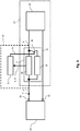
- FIG. 2 shows a schematic view of the current sensor 2 in a circuit 22.
- the current sensor 2 is connected between an electrical energy source 24 designed as a battery and an electrical consumer 26, the electrical current 7 to be detected being conducted to the current sensor 2 via a first battery pole 28 of the battery 24 and one of the two line sections 4 .
- the current 7 to be detected is then conducted to the electrical consumer 26 via the other of the two line sections 6 and returns from the electrical consumer to the battery 24 via a return line 30 and a second battery pole 32.
- the current sensor 2 is connected to the evaluation circuit 12 via measuring lines 8, 10, the measuring lines 8, 10 being able to transmit the voltage drop 14 across the current sensor 2 but also other signals necessary for the measurement, such as a control signal with which the voltage drop 14 at one active shunt can be kept constant.
- a control signal with which the voltage drop 14 at one active shunt can be kept constant please refer to the DE 10 2011 078 548 A1 referred.
- the evaluation circuit 12 outputs a state change signal 34 with which it can change a circuit state of the circuit 22.
- the circuit state can be any influencing variable that changes the electrical current 7 to be detected.
- Such influencing variables can be, for example, the wiring of the circuit 22 or one that acts on the circuit 22 Be temperature that change the electric current 7 to be detected.
- the state of the electrical circuit 22 is changed with the state change signal 34 such that the electrical current 7 to be detected changes in a known manner.
- the in Fig. 1 change shown measuring current 20 flowing through the current sensor 2 in the known manner. If he does not do so, some of the electrical current 7 to be detected flows via a defect in the circuit 22, such as the impurity 18 as a parasitic current 16, so that the measuring current 20 is falsified.
- the evaluation circuit 12 can therefore plausibility check the measurement current 20 detected with the current sensor 2.
- the current sensor 2 is constructed via two individual shunts 36, 38 connected in parallel, the second individual shunt 38 being able to be removed from the parallel connection via a switch 40 which can be controlled by the status change signal 34.
- the evaluation circuit first detects the current 7 to be recorded via the measuring current 20 with both individual shunts 36, 38 in the common parallel connection and stores the value of the measuring current 20, for example, in an internal memory (not shown). It then disconnects the second individual shunt 38 from the parallel connection via the status change signal 34 and detects the value of the measurement current 20 again.
- the two recorded values now depend on one another in a manner known to the person skilled in the art.
- the resistance value of the two individual shunts 36, 38 is the same, for example, the value of the measuring current 20 would have to be doubled after the second individual shunt 38 was switched off. If it does not, a parasitic current 18 flows.
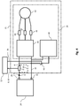
- the electrical consumer 26 comprises a three-phase electric motor 42, which is supplied with electrical energy from the battery 24 via a converter 44 in a manner known to the person skilled in the art.
- a single-phase current sensor 46 can be arranged in each phase in order to carry out measurement tasks known to the person skilled in the art, such as, for example, the detection of the magnetic stator field.
- an electric heater 48 is connected in parallel to the converter 44, which can be separated from the parallel connection via the switch 40 which can be switched by means of the status change signal 34.
- the evaluation device 20 can switch on the electrical heater 48 and measure the value by which the measuring current 20 has risen through the current sensor 20. This value must match the current consumption of the electrical heater 48. If it does not, part of the current 7 to be detected flows as a parasitic current 18.
- the single-phase current sensors 46 can also be checked for their fault-free function using the method presented in the present application.
- Fig. 5 Referred to a qualitative Course 50 of the measuring current 18 over time 52, which with the in Fig. 4 shown arrangement is included.
- the electrical heater 48 is preferably switched on as an additional electrical consumer at a start time 54 when the measurement current 20 has settled to a stationary first value 56.
- the measurement current 20 rises and swings to a second stationary value 58, which can be measured at the earliest at a time 60 at which this settling is complete.
- the time between these two times is usually in the range of seconds.
- the amount 62 should correspond to the difference between the two values 58 and 56 of the measurement current 20 of the current consumption of the electrical heater.
Landscapes
- Physics & Mathematics (AREA)
- General Physics & Mathematics (AREA)
- Chemical & Material Sciences (AREA)
- Engineering & Computer Science (AREA)
- Combustion & Propulsion (AREA)
- Measurement Of Current Or Voltage (AREA)
Applications Claiming Priority (3)
| Application Number | Priority Date | Filing Date | Title |
|---|---|---|---|
| DE102012215946.0A DE102012215946A1 (de) | 2012-09-07 | 2012-09-07 | Schaltung zum Leiten eines elektrischen Stromes |
| PCT/EP2013/068407 WO2014037465A1 (fr) | 2012-09-07 | 2013-09-05 | Procédé et circuit permettant de contrôler la plausibilité d'un résultat de mesure de capteur de courant |
| EP13759726.6A EP2893365A1 (fr) | 2012-09-07 | 2013-09-05 | Procédé et circuit permettant de contrôler la plausibilité d'un résultat de mesure de capteur de courant |
Related Parent Applications (1)
| Application Number | Title | Priority Date | Filing Date |
|---|---|---|---|
| EP13759726.6A Division EP2893365A1 (fr) | 2012-09-07 | 2013-09-05 | Procédé et circuit permettant de contrôler la plausibilité d'un résultat de mesure de capteur de courant |
Publications (1)
| Publication Number | Publication Date |
|---|---|
| EP3660531A1 true EP3660531A1 (fr) | 2020-06-03 |
Family
ID=49150938
Family Applications (2)
| Application Number | Title | Priority Date | Filing Date |
|---|---|---|---|
| EP13759726.6A Pending EP2893365A1 (fr) | 2012-09-07 | 2013-09-05 | Procédé et circuit permettant de contrôler la plausibilité d'un résultat de mesure de capteur de courant |
| EP19216038.0A Withdrawn EP3660531A1 (fr) | 2012-09-07 | 2013-09-05 | Méthode et circuit de vérification de la plausibilité du résultat de la mesure d'un capteur de courant |
Family Applications Before (1)
| Application Number | Title | Priority Date | Filing Date |
|---|---|---|---|
| EP13759726.6A Pending EP2893365A1 (fr) | 2012-09-07 | 2013-09-05 | Procédé et circuit permettant de contrôler la plausibilité d'un résultat de mesure de capteur de courant |
Country Status (7)
| Country | Link |
|---|---|
| US (1) | US9651586B2 (fr) |
| EP (2) | EP2893365A1 (fr) |
| JP (1) | JP2015529332A (fr) |
| KR (1) | KR102110002B1 (fr) |
| CN (1) | CN104603631B (fr) |
| DE (1) | DE102012215946A1 (fr) |
| WO (1) | WO2014037465A1 (fr) |
Families Citing this family (8)
| Publication number | Priority date | Publication date | Assignee | Title |
|---|---|---|---|---|
| DE102014200200A1 (de) * | 2014-01-09 | 2015-07-09 | Robert Bosch Gmbh | Ermittlung einer Stromstärke eines in eine oder aus einer Batterie fließenden elektrischen Stroms |
| DE102014208680A1 (de) * | 2014-05-08 | 2015-11-12 | Robert Bosch Gmbh | Verfahren zur Überwachung von Stromsensoren |
| DE102015212080B4 (de) * | 2015-06-29 | 2017-06-14 | Continental Automotive Gmbh | Verfahren zum Ermitteln der Abweichungen der gemessenen Stromist- von Stromsollwerten in einer Anzahl parallel geschalteter, stromgeregelter Schaltpfade |
| US10421367B2 (en) * | 2015-10-30 | 2019-09-24 | Faraday & Future Inc. | Electric vehicle battery test |
| CN107861086A (zh) * | 2017-12-27 | 2018-03-30 | 北京东方计量测试研究所 | 一种应用于空间的电流传感器在轨校准方法及装置 |
| DE102018206804A1 (de) | 2018-05-03 | 2019-11-07 | Siemens Aktiengesellschaft | Erkennung von Unterbrechungen eines Stromkreises |
| US11391805B2 (en) | 2019-05-10 | 2022-07-19 | Hamilton Sundstrand Corporation | Systems and methods for current sense resistor built-in-test |
| DE102022001529A1 (de) | 2022-05-02 | 2023-11-02 | Mercedes-Benz Group AG | Überwachungsvorrichtung zur Überwachung einer Batterie eines zumindest teilweise elektrisch betriebenen Kraftfahrzeugs sowie Verfahren |
Citations (4)
| Publication number | Priority date | Publication date | Assignee | Title |
|---|---|---|---|---|
| WO2003081263A1 (fr) * | 2002-03-22 | 2003-10-02 | Robert Bosch Gmbh | Dispositif et procede de controle d'un circuit electrique |
| JP2009100551A (ja) * | 2007-10-17 | 2009-05-07 | Yokogawa Electric Corp | 電流検出装置 |
| DE102011078548A1 (de) | 2010-07-01 | 2012-01-05 | Continental Teves Ag & Co. Ohg | Stromsensor |
| DE102010041275A1 (de) * | 2010-09-23 | 2012-03-29 | Sb Limotive Company Ltd. | Verfahren zur Überprüfung der ordnungsgemäßen Funktionsweise eines Stromsensors |
Family Cites Families (21)
| Publication number | Priority date | Publication date | Assignee | Title |
|---|---|---|---|---|
| US3555476A (en) * | 1968-10-04 | 1971-01-12 | Michael B Brenner | Leakage current sensor |
| JPH07104366B2 (ja) * | 1986-09-26 | 1995-11-13 | 日立電子エンジニアリング株式会社 | 電流測定回路 |
| JPH02128964A (ja) | 1988-11-10 | 1990-05-17 | Mitsubishi Automob Eng Co Ltd | シリンダ装置 |
| JPH0719008Y2 (ja) * | 1989-03-31 | 1995-05-01 | 横河電機株式会社 | 電流測定器 |
| JP3917305B2 (ja) * | 1998-10-22 | 2007-05-23 | ミネベア株式会社 | モータ駆動回路 |
| JP2002139520A (ja) | 2000-11-02 | 2002-05-17 | Advantest Corp | 電圧印加電流測定装置 |
| EP1348970B1 (fr) * | 2002-03-26 | 2007-06-20 | ABB Schweiz AG | Test de validité des transformateurs de courant dans des sous-stations |
| DE10343179A1 (de) * | 2003-09-18 | 2005-04-14 | Robert Bosch Gmbh | Vorrichtung zur Strommessung |
| CN2758789Y (zh) | 2004-12-28 | 2006-02-15 | 中达电通股份有限公司 | 霍尔电流传感器故障侦测电路 |
| JP2007003451A (ja) | 2005-06-27 | 2007-01-11 | Nissan Motor Co Ltd | 電流センサの異常検出装置 |
| JP2007192723A (ja) * | 2006-01-20 | 2007-08-02 | Nissan Motor Co Ltd | 電流センサ補正システム及び電流センサ補正方法 |
| CN201188127Y (zh) | 2008-03-20 | 2009-01-28 | 上海市电力公司 | 用于测量用光电电流互感器准确度试验的回路装置 |
| JP2010019805A (ja) | 2008-07-14 | 2010-01-28 | Panasonic Corp | 検出電流補正回路、及びこれを用いた電池パック |
| WO2010068223A1 (fr) * | 2008-12-13 | 2010-06-17 | Hewlett-Packard Development Company, L.P. | Systèmes et procédés de mise à l'échelle d'un signal dans un circuit de correction de facteur de puissance |
| CN101493508B (zh) | 2009-01-13 | 2012-03-14 | 国网电力科学研究院 | 一种特高压直流电流互感器的校准试验装置 |
| US8138704B2 (en) | 2009-05-22 | 2012-03-20 | GM Global Technology Operations LLC | Methods and systems for detecting current sensor error |
| CN101927785B (zh) * | 2009-06-26 | 2012-08-08 | 上海联盛汽车电子有限公司 | 具有pmsm电流传感器误差自校正功能的电动助力转向系统 |
| CN101644752A (zh) | 2009-08-14 | 2010-02-10 | 河南电力试验研究院 | 一种电流互感器在线精度检测方法和系统 |
| JP2011109852A (ja) * | 2009-11-19 | 2011-06-02 | Toyota Motor Corp | 電源システムの制御装置およびそれを搭載する車両 |
| CN101718852B (zh) * | 2009-12-04 | 2012-01-04 | 中国电力科学研究院 | 一种霍尔电流传感器在线检测校准方法 |
| TW201350869A (zh) * | 2012-06-07 | 2013-12-16 | Askey Computer Corp | 電流量測系統 |
-
2012
- 2012-09-07 DE DE102012215946.0A patent/DE102012215946A1/de active Pending
-
2013
- 2013-09-05 WO PCT/EP2013/068407 patent/WO2014037465A1/fr active Application Filing
- 2013-09-05 US US14/426,515 patent/US9651586B2/en active Active
- 2013-09-05 EP EP13759726.6A patent/EP2893365A1/fr active Pending
- 2013-09-05 EP EP19216038.0A patent/EP3660531A1/fr not_active Withdrawn
- 2013-09-05 JP JP2015530393A patent/JP2015529332A/ja active Pending
- 2013-09-05 KR KR1020157008866A patent/KR102110002B1/ko active IP Right Grant
- 2013-09-05 CN CN201380046565.7A patent/CN104603631B/zh active Active
Patent Citations (4)
| Publication number | Priority date | Publication date | Assignee | Title |
|---|---|---|---|---|
| WO2003081263A1 (fr) * | 2002-03-22 | 2003-10-02 | Robert Bosch Gmbh | Dispositif et procede de controle d'un circuit electrique |
| JP2009100551A (ja) * | 2007-10-17 | 2009-05-07 | Yokogawa Electric Corp | 電流検出装置 |
| DE102011078548A1 (de) | 2010-07-01 | 2012-01-05 | Continental Teves Ag & Co. Ohg | Stromsensor |
| DE102010041275A1 (de) * | 2010-09-23 | 2012-03-29 | Sb Limotive Company Ltd. | Verfahren zur Überprüfung der ordnungsgemäßen Funktionsweise eines Stromsensors |
Also Published As
| Publication number | Publication date |
|---|---|
| EP2893365A1 (fr) | 2015-07-15 |
| US20150219696A1 (en) | 2015-08-06 |
| US9651586B2 (en) | 2017-05-16 |
| WO2014037465A1 (fr) | 2014-03-13 |
| CN104603631A (zh) | 2015-05-06 |
| KR20150053273A (ko) | 2015-05-15 |
| KR102110002B1 (ko) | 2020-05-12 |
| CN104603631B (zh) | 2017-12-29 |
| DE102012215946A1 (de) | 2014-05-28 |
| JP2015529332A (ja) | 2015-10-05 |
Similar Documents
| Publication | Publication Date | Title |
|---|---|---|
| EP3660531A1 (fr) | Méthode et circuit de vérification de la plausibilité du résultat de la mesure d'un capteur de courant | |
| DE102009047856B4 (de) | System und Verfahren zur Identifikation von Problemen bei Strom- und Spannungsmessung | |
| EP3126181B1 (fr) | Procédé de contrôle d'une connexion entre un réseau basse tension et une batterie, et véhicule automobile | |
| DE102012205401A1 (de) | Vorrichtung und Verfahren zur redundanten Bestimmung eines über die Pole einer Batterie fließenden Batteriestroms | |
| DE102007046483A1 (de) | Schaltungsanordnung zur Überwachung einer elektrischen Isolation | |
| EP3631976B1 (fr) | Procédé servant à identifier un contact défectueux dans une installation photovoltaïque | |
| DE102011083307A1 (de) | Vorrichtung zur Messung eines Batteriestroms | |
| DE102014219807B4 (de) | Verfahren und Vorrichtung zur Prüfung einer Funktionsfähigkeit eines Stromsensors und Fahrzeug | |
| DE102012200245A1 (de) | Selbstdiagnoseschaltung und Magnetfelddetektionsvorrichtung | |
| DE19820207A1 (de) | Vorrichtung zum Überprüfen der Antenne eines in einem Kraftfahrzeug vorhandenen Systems, insbesondere Wegfahrsperrensystem | |
| DE102018123552A1 (de) | Vorrichtung und verfahren zum aufwecken einer fahrzeugbatterie | |
| WO2016041658A1 (fr) | Étalonnage de capteurs de courant au moyen d'un courant de référence | |
| EP3233578B1 (fr) | Dispositif de surveillance pour au moins un circuit d'allumage pour un moyen de protection de personnes pour un véhicule, et procédé servant à faire fonctionner un dispositif de surveillance | |
| EP2553482B1 (fr) | Circuit électrique de véhicule et commande pour ce circuit | |
| DE102005004174B4 (de) | Verfahren zur Diagnose einer Kraftfahrzeugbatterie | |
| WO2016042109A1 (fr) | Procédé d'étalonnage continu de systèmes de mesure du courant dans des véhicules automobiles | |
| EP3947946B1 (fr) | Procédé de diagnostic de capteurs de gaz d'échappement | |
| DE102012223573A1 (de) | Verfahren und Vorrichtung zum Überwachen von Signalpegeln | |
| EP3532857B1 (fr) | Dispositif et procédé pour le diagnostic de la détection d'un courant électrique polyphasé | |
| DE102007031303A1 (de) | Verfahren und Vorrichtung zur Ermittlung einer mit dem Batterieladezustand korrelierenden Zustandsgröße einer Kraftfahrzeugbatterie unter Verwendung eines selbstlernenden Batteriemodells | |
| EP3807660B1 (fr) | Procédé et dispositif de vérification électrique d'un module électrique | |
| EP2362232A2 (fr) | Unité de surveillance pour modules solaires | |
| DE102019110994B4 (de) | Vorrichtung und Verfahren zur Korrektur eines Messwertes | |
| EP0927356B2 (fr) | Procede de verification de composants electriques et dispositif permettant de mettre ledit procede en oeuvre | |
| DE102017223318A1 (de) | Schaltung zur Erfassung einer Eingangsgröße in einem elektrischen Steuergerät |
Legal Events
| Date | Code | Title | Description |
|---|---|---|---|
| PUAI | Public reference made under article 153(3) epc to a published international application that has entered the european phase |
Free format text: ORIGINAL CODE: 0009012 |
|
| STAA | Information on the status of an ep patent application or granted ep patent |
Free format text: STATUS: THE APPLICATION HAS BEEN PUBLISHED |
|
| AC | Divisional application: reference to earlier application |
Ref document number: 2893365 Country of ref document: EP Kind code of ref document: P |
|
| AK | Designated contracting states |
Kind code of ref document: A1 Designated state(s): AL AT BE BG CH CY CZ DE DK EE ES FI FR GB GR HR HU IE IS IT LI LT LU LV MC MK MT NL NO PL PT RO RS SE SI SK SM TR |
|
| STAA | Information on the status of an ep patent application or granted ep patent |
Free format text: STATUS: REQUEST FOR EXAMINATION WAS MADE |
|
| 17P | Request for examination filed |
Effective date: 20201203 |
|
| RBV | Designated contracting states (corrected) |
Designated state(s): AL AT BE BG CH CY CZ DE DK EE ES FI FR GB GR HR HU IE IS IT LI LT LU LV MC MK MT NL NO PL PT RO RS SE SI SK SM TR |
|
| STAA | Information on the status of an ep patent application or granted ep patent |
Free format text: STATUS: THE APPLICATION IS DEEMED TO BE WITHDRAWN |
|
| 18D | Application deemed to be withdrawn |
Effective date: 20220401 |