EP3653403B1 - Luftreifen für ein motorrad - Google Patents
Luftreifen für ein motorrad Download PDFInfo
- Publication number
- EP3653403B1 EP3653403B1 EP18831767.1A EP18831767A EP3653403B1 EP 3653403 B1 EP3653403 B1 EP 3653403B1 EP 18831767 A EP18831767 A EP 18831767A EP 3653403 B1 EP3653403 B1 EP 3653403B1
- Authority
- EP
- European Patent Office
- Prior art keywords
- tire
- groove
- width
- tire width
- inclined groove
- Prior art date
- Legal status (The legal status is an assumption and is not a legal conclusion. Google has not performed a legal analysis and makes no representation as to the accuracy of the status listed.)
- Active
Links
Images


Classifications
-
- B—PERFORMING OPERATIONS; TRANSPORTING
- B60—VEHICLES IN GENERAL
- B60C—VEHICLE TYRES; TYRE INFLATION; TYRE CHANGING; CONNECTING VALVES TO INFLATABLE ELASTIC BODIES IN GENERAL; DEVICES OR ARRANGEMENTS RELATED TO TYRES
- B60C11/00—Tyre tread bands; Tread patterns; Anti-skid inserts
- B60C11/03—Tread patterns
- B60C11/13—Tread patterns characterised by the groove cross-section, e.g. for buttressing or preventing stone-trapping
- B60C11/1307—Tread patterns characterised by the groove cross-section, e.g. for buttressing or preventing stone-trapping with special features of the groove walls
- B60C11/1315—Tread patterns characterised by the groove cross-section, e.g. for buttressing or preventing stone-trapping with special features of the groove walls having variable inclination angles, e.g. warped groove walls
-
- B—PERFORMING OPERATIONS; TRANSPORTING
- B60—VEHICLES IN GENERAL
- B60C—VEHICLE TYRES; TYRE INFLATION; TYRE CHANGING; CONNECTING VALVES TO INFLATABLE ELASTIC BODIES IN GENERAL; DEVICES OR ARRANGEMENTS RELATED TO TYRES
- B60C11/00—Tyre tread bands; Tread patterns; Anti-skid inserts
- B60C11/03—Tread patterns
- B60C11/0302—Tread patterns directional pattern, i.e. with main rolling direction
-
- B—PERFORMING OPERATIONS; TRANSPORTING
- B60—VEHICLES IN GENERAL
- B60C—VEHICLE TYRES; TYRE INFLATION; TYRE CHANGING; CONNECTING VALVES TO INFLATABLE ELASTIC BODIES IN GENERAL; DEVICES OR ARRANGEMENTS RELATED TO TYRES
- B60C11/00—Tyre tread bands; Tread patterns; Anti-skid inserts
- B60C11/03—Tread patterns
- B60C11/13—Tread patterns characterised by the groove cross-section, e.g. for buttressing or preventing stone-trapping
- B60C11/1307—Tread patterns characterised by the groove cross-section, e.g. for buttressing or preventing stone-trapping with special features of the groove walls
- B60C11/1323—Tread patterns characterised by the groove cross-section, e.g. for buttressing or preventing stone-trapping with special features of the groove walls asymmetric
-
- B—PERFORMING OPERATIONS; TRANSPORTING
- B60—VEHICLES IN GENERAL
- B60C—VEHICLE TYRES; TYRE INFLATION; TYRE CHANGING; CONNECTING VALVES TO INFLATABLE ELASTIC BODIES IN GENERAL; DEVICES OR ARRANGEMENTS RELATED TO TYRES
- B60C11/00—Tyre tread bands; Tread patterns; Anti-skid inserts
- B60C11/03—Tread patterns
- B60C2011/0337—Tread patterns characterised by particular design features of the pattern
- B60C2011/0339—Grooves
- B60C2011/0358—Lateral grooves, i.e. having an angle of 45 to 90 degees to the equatorial plane
- B60C2011/0372—Lateral grooves, i.e. having an angle of 45 to 90 degees to the equatorial plane with particular inclination angles
-
- B—PERFORMING OPERATIONS; TRANSPORTING
- B60—VEHICLES IN GENERAL
- B60C—VEHICLE TYRES; TYRE INFLATION; TYRE CHANGING; CONNECTING VALVES TO INFLATABLE ELASTIC BODIES IN GENERAL; DEVICES OR ARRANGEMENTS RELATED TO TYRES
- B60C11/00—Tyre tread bands; Tread patterns; Anti-skid inserts
- B60C11/03—Tread patterns
- B60C2011/0337—Tread patterns characterised by particular design features of the pattern
- B60C2011/0339—Grooves
- B60C2011/0381—Blind or isolated grooves
-
- B—PERFORMING OPERATIONS; TRANSPORTING
- B60—VEHICLES IN GENERAL
- B60C—VEHICLE TYRES; TYRE INFLATION; TYRE CHANGING; CONNECTING VALVES TO INFLATABLE ELASTIC BODIES IN GENERAL; DEVICES OR ARRANGEMENTS RELATED TO TYRES
- B60C2200/00—Tyres specially adapted for particular applications
- B60C2200/10—Tyres specially adapted for particular applications for motorcycles, scooters or the like
Definitions
- the present invention relates to a motorcycle pneumatic tire (hereinafter, also simply referred to as "tire”), more particularly a motorcycle pneumatic tire pertaining to an improvement of a tread portion.
- Two-wheeled vehicles have a characteristic of making turns by tilting the vehicle body, which is different from four-wheeled vehicles such as passenger cars, trucks and buses; therefore, motorcycle pneumatic tires have a shape in which the crown section has a smaller radius of curvature with a rounder cross-section as compared to four-wheeled vehicle tires.
- a tread central portion mainly comes in contact with the ground during straight running of motorcycle, while a tread shoulder portion comes in contact with the ground during turning.
- the groove width is set to be narrower at, for example, about 4 to 5 mm, than in tires of other types so as to make it easier to design land portions.
- the inclination angle of grooves with respect to the tire circumferential direction in the tire central portion is set to be small, and tends to increase toward the tire shoulder portions so as to ensure lateral rigidity.
- Patent Document 1 discloses a motorcycle pneumatic tire in which: a large number of first inclined grooves inclining across an equatorial plane are arranged at intervals along the circumferential direction within a range of the surface coming into contact with the ground during straight running; second inclined grooves that correspond to the respective first inclined grooves and have the same inclination directions with respect to the equatorial plane as those of the corresponding first inclined grooves are arranged at positions away from the respective first inclined grooves on the outer ground-contact surface on one side; a limited length part of a widthwise center line of each first inclined groove and a limited length part of a widthwise center line of the corresponding second inclined groove are both on a common curved line whose positive/negative direction of curvature does not change; an projection image of each first inclined groove and that of the corresponding second inclined groove on a plane passing through the tire axis are separated from each other by a distance ⁇ in the tire axial direction; and an projection
- JP2012-153318A and JP2014-210470A Attention is also drawn to the disclosures of JP2012-153318A and JP2014-210470A , whereby JP2012-153318A is forming the preamble of claim 1.
- Patent Document 1 JP2010-184539A (Claims, etc.)
- One important performance of a motorcycle pneumatic tire is the wet grip performance during turning of motorcycle.
- the grip performance and the wet performance are both satisfied by appropriately arranging plural inclined grooves inclining across the equatorial plane within a range of the surface coming into contact with the ground during straight running; however, the wet grip performance during turning is not examined.
- an object of the present invention is to provide a motorcycle pneumatic tire in which the wet grip performance during turning is improved while the steering stability during turning is ensured without such an adverse effect on the wear performance as in the prior art.
- the present inventors intensively studied to discover that the above-described problems can be solved by arranging prescribed grooves on the tire ground-contact surface under prescribed conditions, thereby completing the present invention.
- the present invention is a motorcycle pneumatic tire as claimed in claim 1.
- the angle ⁇ A formed by the groove wall of the tire width-direction outer end of the first inclined groove with respect to the direction perpendicular to the tire surface be in a range of 40° to 50°
- the angle ⁇ B formed by the groove wall of the tire width-direction inner end of the short groove with respect to the direction perpendicular to the tire surface be in a range of 15° to 25°.
- a tire width-direction distance between the tire width-direction outer end of the first inclined groove and the tire width-direction inner end of the short groove be in a range of 7 to 13% of a tread half width TW/2.
- a motorcycle pneumatic tire in which the wet grip performance during turning is improved while ensuring the steering stability during turning can be provided.
- FIG. 1 is a widthwise cross-sectional view illustrating a motorcycle pneumatic tire of the present invention.
- the illustrated motorcycle pneumatic tire includes: a pair of bead portions 11; a pair of side wall portions 12 continuously extending on the respective bead portions; and a tread portion 13 toroidally extending between the side wall portions 12.
- the illustrated motorcycle pneumatic tire also includes: at least one (e.g., 1 or 2) carcass 1 which reinforces the above-described portions between the pair of the bead portions 11; and at least one (e.g., 1 or 2) belt layer 2 which is arranged on a tire radial-direction outer side of the carcass 1 and is formed by spirally winding a reinforcing cord in a circumferential direction.
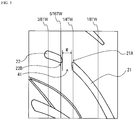
- FIG. 2 is a partial development view illustrating one example of a tread pattern of a motorcycle pneumatic tire of the present invention.
- the illustrated tread pattern is a directional pattern that has a designated rotation direction when mounted on a motorcycle.
- An arrow in FIG. 2 represents the rotation direction of the tire.
- a first inclined groove 21, which extends on a tire width-direction outer side from the vicinity of a tire equator CL and is inclined in the same direction as the tire rotation direction, and a short groove 22, which is arranged on an extension of a tire width-direction outer end of the first inclined groove 21, are arranged on the tire ground-contact surface.
- FIG. 3 is an enlarged view illustrating the vicinity of the first inclined groove 21 and the short groove 22 arranged on the extension of the first inclined groove 21.
- the reason for arranging the short groove 22 on the extension of the first inclined groove 21 is also because, for example, when the short groove 22 is displaced on either side of the tire circumferential direction and is thus not on the extension of the first inclined groove 21, the rigidity fluctuates and cracking occurs, causing vibration during running.
- a tire width-direction outer end 21A of the first inclined groove 21 is positioned in the vicinity of a point at 1/4 of a tread width TW from the tire equator CL on the tire width-direction outer side, and a tire width-direction inner end 22B of the short groove 22 is positioned in a range of 1/4 to 5/16 of the tread width TW from the tire equator CL on the tire width-direction outer side.
- the phrase "the tire width-direction outer end 21A of the first inclined groove 21 is positioned in the vicinity of a point of 1/4 of the tread width TW from the tire equator CL on the tire width-direction outer side” means that the tire width-direction outer end 21A of the first inclined groove 21 exists in a range of ⁇ 5% of the tread width TW, being centered at the above-described point of 1/4.
- the term "tread width TW” means a tire width-direction distance between tread ends TE, which is measured along the ground-contact surface in a state where the tire is fitted to an application rim and inflated to a prescribed internal pressure with no load.
- application rim refers to a rim defined by an industrial standard that is valid in each region where the tire is manufactured and used, and the term “prescribed internal pressure” refers to an air pressure that corresponds to the maximum load capacity at the application size prescribed in the industrial standard.
- the "industrial standard” is, for example, JATMA YEAR BOOK of Japan Automobile Tyre Manufacturers Association (JATMA) in Japan, STANDARD MANUAL of The European Tyre and Rim Technical Organisation (ETRTO) in Europe, or YEAR BOOK of The Tire and Rim Association, Inc. (TRA) in the U.S.
- the drainage performance of a shoulder portion can be improved by arranging the short groove 22 on the extension of the first inclined groove 21; however, when a land portion 41 between the first inclined groove 21 and the short groove 22 is too close to the shoulder side, the lateral rigidity during turning of the motorcycle cannot be obtained sufficiently. Therefore, in the present invention, the positions of the tire width-direction outer end 21A of the first inclined groove 21 and the tire width-direction inner end 22B of the short groove 22 are defined as described above, whereby the land portion 41 is positioned in the range of 1/4 to 5/16 of the tread width TW from the tire equator CL on the tire width-direction outer side, which range where the land portion 41 frequently comes in contact with the ground during turning of the motorcycle. By this, a high lateral rigidity can be ensured during turning of the motorcycle.
- the first inclined groove 21 is arranged such that, as illustrated, the inclination angle thereof with respect to the tire circumferential direction increases toward the tire width-direction outer side.
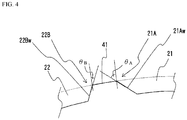
- FIG. 4 is a schematic cross-sectional view taken along the extending direction of the first inclined groove 21 and the short groove 22 arranged on the extension of the first inclined groove 21.
- an angle ⁇ A formed by a groove wall 21Aw of the tire width-direction outer end 21A of the first inclined groove 21 with respect to the direction perpendicular to the tire surface, and an angle ⁇ B formed by a groove wall 22Bw of the tire width-direction inner end 22B of the short groove 22 with respect to the direction perpendicular to the tire surface satisfy a relationship of ⁇ A > ⁇ B .
- a motorcycle pneumatic tire in which the wet grip performance during turning of a motorcycle is improved by enhancing the drainage performance, while the lateral rigidity is ensured by securing the steering stability during turning of the motorcycle, can be realized.
- the angle ⁇ A formed by the groove wall 21Aw of the tire width-direction outer end 21A of the first inclined groove 21 with respect to the direction perpendicular to the tire surface is in a range of preferably 40° or larger, more preferably 42° or larger, but preferably 50° or smaller, more preferably 48° or smaller
- the angle ⁇ B formed by the groove wall 22Bw of the tire width-direction inner end 22B of the short groove 22 with respect to the direction perpendicular to the tire surface is in a range of preferably 15° or larger, more preferably 17° or larger, but preferably 25° or smaller, more preferably 23° or smaller.
- a tire width-direction distance w between the tire width-direction outer end 21A of the first inclined groove 21 and the tire width-direction inner end 22B of the short groove 22 is preferably in a range of 7% or greater, particularly 8% or greater, but 13% or less, particularly 12% or less, of the tread half width TW/2.
- the regions of 1/8 to 1/4 and 1/4 to 3/8 of the tread width TW from the tire equator CL on the tire width-direction outer side have the largest number of grooves arranged on the ground-contact surface.
- the number of grooves By setting the number of grooves to be the largest in these regions, the pattern rigidity on the inner side of the ground-contact surface is reduced during turning of the motorcycle as compared to the pattern rigidity on the outer side of the ground-contact surface; therefore, the shearing force in slippery regions is dispersed, whereby an effect of improving the wet grip performance can be obtained.
- the number of grooves included in each region is determined by measuring the tire width-direction distance between the tire widthwise ends of each groove in each region and counting the number of grooves that are included across 70% or more of the tire width direction of each region.
- the term “groove” refers to a groove having a maximum groove width of not less than 2 mm or a maximum groove depth of not less than 2 mm, and the term does not encompass, for example, such a shallow groove whose maximum groove width or maximum groove depth does not satisfy the above-described range.
- the term “groove width” refers to the width of an opening at a cross-section perpendicular to the extending direction of the groove of interest.
- a second inclined groove 23 and a third inclined groove 24 each of which extends from the tire width-direction inner side toward the tire width-direction outer side and is inclined in the same direction as the tire rotation direction, may be arranged on the tire ground-contact surface.
- the second inclined groove 23 and the third inclined groove 24 may be arranged at substantially equal intervals along the tire circumferential direction, and their inclination angles with respect to the tire circumferential direction increase toward the tire width-direction outer side in the same manner as the first inclined groove.
- decorative grooves 31 and 32 may be arranged in addition to the first to the third inclined grooves.
- the term "decorative groove” refers to a groove having a narrow width and a shallow depth, such as a groove that has a maximum groove width of 0.1 mm or larger, preferably 0.5 mm or larger, but less than 2.0 mm, preferably 1.5 mm or less, and a maximum groove depth of 0.1 mm or greater, preferably 0.2 mm or greater, but less than 2.0 mm, preferably 0.5 mm or less.
- the arrangement pitch of the inclined grooves and the decorative grooves is not particularly restricted and, for example, the arrangement pitch may be about 1/15 to 1/22 of the whole circumferential length of the tire. Further, in the present invention, the positions of the inclined grooves and the decorative grooves along the tire circumferential direction may be arranged alternately to be shifted, for example, by 1/2 to 1/3 of the arrangement pitch on one side and the other side of the ground-contact surface sandwiching the tire equatorial plane CL.
- the arrangement conditions of the grooves provided on the tire ground-contact surface be defined as described above, and this enables to attain the expected effects.
- the details of other tire structures, materials to be used and the like are not particularly restricted and, for example, the tire of the present invention can be configured as follows.
- the belt layer 2 a spiral belt formed by spirally winding an elongated rubber-coated cord obtained by coating a single reinforcing cord with a rubber or a strip-form ply obtained by coating plural reinforcing cords with a rubber and whose cord direction is substantially the same as the tire circumferential direction, can be used.
- the belt layer 2 may be composed of two or more inclined belt layers that are arranged such that their cord directions intersect with each other between the layers.
- the reinforcing cord(s) can be selected as appropriate from steel cords, cords made of organic fibers, such as fibers of aromatic polyamide (aramid, e.g., trade name "KEVLAR(registered trademark)” manufactured by DuPont (trademark)), polyethylene naphthalate (PEN), polyethylene terephthalate (PET), rayon, ZYLON (registered trademark) (poly-p-phenylene benzobisoxazole (PBO) fiber) or aliphatic polyamide (nylon), and cords made of glass fibers, carbon fibers or the like. From the standpoint of ensuring the wear life and the high-speed durability at high levels, it is preferred to use a steel cord.
- aromatic polyamide aramid, e.g., trade name "KEVLAR(registered trademark)” manufactured by DuPont (trademark)
- PEN polyethylene naphthalate
- PET polyethylene terephthalate
- rayon rayon
- bead cores 3 are each embedded in the pair of the bead portions 11, and the carcass 1 is folded around the bead cores 3 from the inside to the outside of the tire and thereby anchored.
- the ends of the carcass 1 may each be sandwiched from both sides and anchored by bead wires, although this is not illustrated in the drawing.
- an inner liner (not illustrated) is formed as an innermost layer of the tire of the present invention.
- the tire of the present invention can be applied as both a front tire and a rear tire of a motorcycle, and the tire of the present invention is particularly suitable as a front tire and may be applied as a tire having either a radial structure or a bias structure.
- Example 1 having the cross-sectional structure and the tread pattern as illustrated in FIGs. 1 and 2 was produced at a tire size of MCR120/70ZR17M/C.
- the carcass 1 was provided in two layers, and rayon was used as a reinforcing cord. Further, as the belt layer 2, a mono-spiral belt obtained by spirally winding a rubber-coated steel cord was used.
- a first inclined groove extending on the tire width-direction outer side from the vicinity of the tire equator and being inclined in the same direction as the tire rotation direction, and a short groove arranged on the extension of the tire width-direction outer end of the first inclined groove were provided on the tire ground-contact surface.
- the tire width-direction outer end of the first inclined groove was positioned in the vicinity of a point at 1/4 of the tread width TW from the tire equator on the tire width-direction outer side
- the tire width-direction inner end of the short groove was positioned in a range of 1/4 to 5/16 of the tread width TW from the tire equator on the tire width-direction outer side.
- test tires were each fitted to a rim having a size of MT5.5 ⁇ 17, mounted on a 1,000-cc motorcycle as its front tire, and then inflated to an internal pressure of 250 kPa.
- a commercially available tire having a size of MCR180/55ZR17M/C was used as the rear tire.
Claims (3)
- Motorrad-Luftreifen, der Folgendes umfasst:ein Paar von Wulstabschnitten (11),ein Paar von Seitenwandabschnitten (12), die sich durchgehend an den jeweiligen Wulstabschnitten (11) erstrecken,einen Laufflächenabschnitt (13), der sich kreisringförmig zwischen den Seitenwandabschnitten (12) erstreckt,mindestens eine Karkasse (1), welche die jeweiligen Abschnitte zwischen dem Paar von Wulstabschnitten (11) verstärkt, undeine ausgewiesene Rotationsrichtung, wenn er an einem Motorrad montiert ist, wobeider Motorrad-Luftreifen ferner, auf seiner Bodenberührungsfläche, Folgendes umfasst: eine erste geneigte Rille (21), die sich auf einer in Reifenbreitenrichtung äußeren Seite von der Nähe eines Reifenäquators (CL) aus erstreckt und in der gleichen Richtung wie die Reifenrotationsrichtung geneigt ist, und eine kurze Rille (22), die an einer Verlängerung eines in Reifenbreitenrichtung äußeren Endes (21A) der ersten geneigten Rille (21) angeordnet ist,eine Laufflächenbreite TW ein Abstand zwischen Laufflächenenden (TE) in Reifenbreitenrichtung ist, der entlang der Bodenberührungsfläche in einem Zustand gemessen wird, in dem der Reifen an einer Einsatzfelge angebracht und bis zu einem vorgeschriebenen Innendruck ohne Last aufgeblasen ist, wobei sich der "vorgeschriebene Innendruck" auf einen Luftdruck bezieht, welcher der maximalen Tragfähigkeit bei der Einsatzgröße entspricht, die in dem Industriestandard vorgeschrieben ist,das in Reifenbreitenrichtung äußere Ende (21A) der ersten geneigten Rille (21) in der Nähe eines Punktes bei 1/4 der Laufflächenbreite TW von dem Reifenäquator (CL) auf der in Reifenbreitenrichtung äußeren Seite angeordnet ist, während ein in Reifenbreitenrichtung inneres Ende (22B) der kurzen Rille (22) in einem Bereich von 1/4 bis 5/16 der Laufflächenbreite TW von dem Reifenäquator (CL) auf der in Reifenbreitenrichtung äußeren Seite angeordnet ist, undein Neigungswinkel der ersten geneigten Rille (21) in Bezug auf eine Reifenumfangsrichtung hin zu der in Reifenbreitenrichtung äußeren Seite zunimmt, und dadurch gekennzeichnet, dassein Winkel θA, der durch eine Rillenwand (21Aw) des in Reifenbreitenrichtung äußeren Endes (21A) der ersten geneigten Rille (21) in Bezug auf die Richtung, senkrecht zu der Reifenoberfläche, gebildet wird, und ein Winkel θB, der durch eine Rillenwand (22Bw) des in Reifenbreitenrichtung inneren Endes (22B) der kurzen Rille (22) in Bezug auf die Richtung, senkrecht zu der Reifenoberfläche, gebildet wird, eine Beziehung von θA > θB erfüllen.
- Motorrad-Luftreifen nach Anspruch 1, wobeider Winkel θA, der durch die Rillenwand (21Aw) des in Reifenbreitenrichtung äußeren Endes (21A) der ersten geneigten Rille (21) in Bezug auf die Richtung, senkrecht zu der Reifenoberfläche, gebildet wird, in einem Bereich von 40° bis 50° liegt undder Winkel θB, der durch die Rillenwand (22Bw) des in Reifenbreitenrichtung inneren Endes (22B) der kurzen Rille (22) in Bezug auf die Richtung, senkrecht zu der Reifenoberfläche, gebildet wird, in einem Bereich von 15° bis 25° liegt.
- Motorrad-Luftreifen nach Anspruch 1 oder 2, wobei ein Abstand in Reifenbreitenrichtung zwischen dem in Reifenbreitenrichtung äußeren Ende (21A) der ersten geneigten Rille (21) und dem in Reifenbreitenrichtung inneren Ende (22B) der kurzen Rille (22) in einem Bereich von 7 bis 13 % einer halben Laufflächenbreite TW/2 liegt.
Applications Claiming Priority (2)
| Application Number | Priority Date | Filing Date | Title |
|---|---|---|---|
| JP2017138028A JP6851924B2 (ja) | 2017-07-14 | 2017-07-14 | 自動二輪車用空気入りタイヤ |
| PCT/JP2018/023880 WO2019012964A1 (ja) | 2017-07-14 | 2018-06-22 | 自動二輪車用空気入りタイヤ |
Publications (3)
| Publication Number | Publication Date |
|---|---|
| EP3653403A1 EP3653403A1 (de) | 2020-05-20 |
| EP3653403A4 EP3653403A4 (de) | 2021-01-20 |
| EP3653403B1 true EP3653403B1 (de) | 2021-09-22 |
Family
ID=65001392
Family Applications (1)
| Application Number | Title | Priority Date | Filing Date |
|---|---|---|---|
| EP18831767.1A Active EP3653403B1 (de) | 2017-07-14 | 2018-06-22 | Luftreifen für ein motorrad |
Country Status (5)
| Country | Link |
|---|---|
| US (1) | US11780269B2 (de) |
| EP (1) | EP3653403B1 (de) |
| JP (1) | JP6851924B2 (de) |
| CN (1) | CN110891801B (de) |
| WO (1) | WO2019012964A1 (de) |
Families Citing this family (1)
| Publication number | Priority date | Publication date | Assignee | Title |
|---|---|---|---|---|
| TWI690434B (zh) * | 2019-04-12 | 2020-04-11 | 正新橡膠工業股份有限公司 | 可加強排水性能之輪胎 |
Family Cites Families (12)
| Publication number | Priority date | Publication date | Assignee | Title |
|---|---|---|---|---|
| JP2007210384A (ja) * | 2006-02-08 | 2007-08-23 | Bridgestone Corp | 自動二輪車用空気入りタイヤ |
| EP2181864B1 (de) | 2008-11-04 | 2011-05-18 | Sumitomo Rubber Industries, Ltd. | Luftreifen für ein Motorrad |
| JP5216620B2 (ja) | 2009-02-10 | 2013-06-19 | 株式会社ブリヂストン | 自動二輪車用空気入りタイヤ |
| JP5596580B2 (ja) * | 2011-01-28 | 2014-09-24 | 株式会社ブリヂストン | 自動二輪車用空気入りタイヤ |
| JP2012162160A (ja) * | 2011-02-04 | 2012-08-30 | Bridgestone Corp | 自動二輪車用空気入りタイヤ |
| JP5965138B2 (ja) * | 2011-12-06 | 2016-08-03 | 株式会社ブリヂストン | 自動二輪車用空気入りタイヤ |
| JP5444393B2 (ja) * | 2012-03-01 | 2014-03-19 | 住友ゴム工業株式会社 | 自動二輪車用タイヤ |
| JP2014210470A (ja) * | 2013-04-17 | 2014-11-13 | 住友ゴム工業株式会社 | 自動二輪車用タイヤ |
| JP6508905B2 (ja) | 2014-10-01 | 2019-05-08 | 株式会社ブリヂストン | 自動二輪車用タイヤおよびタイヤセット |
| JP6502689B2 (ja) | 2015-01-30 | 2019-04-17 | 住友ゴム工業株式会社 | 自動二輪車用空気入りタイヤ |
| JP6972986B2 (ja) * | 2017-12-04 | 2021-11-24 | 住友ゴム工業株式会社 | 自動二輪車用タイヤ |
| JP6939495B2 (ja) * | 2017-12-11 | 2021-09-22 | 住友ゴム工業株式会社 | 自動二輪車用タイヤ |
-
2017
- 2017-07-14 JP JP2017138028A patent/JP6851924B2/ja active Active
-
2018
- 2018-06-22 CN CN201880046720.8A patent/CN110891801B/zh active Active
- 2018-06-22 WO PCT/JP2018/023880 patent/WO2019012964A1/ja unknown
- 2018-06-22 EP EP18831767.1A patent/EP3653403B1/de active Active
-
2020
- 2020-01-13 US US16/740,565 patent/US11780269B2/en active Active
Also Published As
| Publication number | Publication date |
|---|---|
| CN110891801B (zh) | 2021-07-23 |
| JP6851924B2 (ja) | 2021-03-31 |
| US20200148007A1 (en) | 2020-05-14 |
| EP3653403A1 (de) | 2020-05-20 |
| CN110891801A (zh) | 2020-03-17 |
| US11780269B2 (en) | 2023-10-10 |
| EP3653403A4 (de) | 2021-01-20 |
| JP2019018676A (ja) | 2019-02-07 |
| WO2019012964A1 (ja) | 2019-01-17 |
Similar Documents
| Publication | Publication Date | Title |
|---|---|---|
| JP5756486B2 (ja) | 空気入りタイヤ | |
| US20040211501A1 (en) | Pneumatic tire | |
| US10870318B2 (en) | Pneumatic tire | |
| JP7298622B2 (ja) | 空気入りタイヤ | |
| US10596860B2 (en) | Pneumatic tire | |
| EP3272553B1 (de) | Motorradreifen | |
| EP3653403B1 (de) | Luftreifen für ein motorrad | |
| EP3653404B1 (de) | Luftreifen für ein motorrad | |
| EP3272554B1 (de) | Motorradreifen | |
| JPH04254205A (ja) | 二輪車用空気入りラジアルタイヤ | |
| EP3695985B1 (de) | Motorradreifen | |
| EP3932695A1 (de) | Motorradreifen | |
| EP3695984B1 (de) | Motorradreifen | |
| EP4059742B1 (de) | Luftreifen für renn-karts | |
| US20220339975A1 (en) | Tire | |
| US11639076B2 (en) | Motorcycle tire | |
| CN113508043B (zh) | 摩托车用轮胎 | |
| US20240092124A1 (en) | Motorcycle tire | |
| US10940720B2 (en) | Tire for motorcycles |
Legal Events
| Date | Code | Title | Description |
|---|---|---|---|
| STAA | Information on the status of an ep patent application or granted ep patent |
Free format text: STATUS: THE INTERNATIONAL PUBLICATION HAS BEEN MADE |
|
| PUAI | Public reference made under article 153(3) epc to a published international application that has entered the european phase |
Free format text: ORIGINAL CODE: 0009012 |
|
| STAA | Information on the status of an ep patent application or granted ep patent |
Free format text: STATUS: REQUEST FOR EXAMINATION WAS MADE |
|
| 17P | Request for examination filed |
Effective date: 20200206 |
|
| AK | Designated contracting states |
Kind code of ref document: A1 Designated state(s): AL AT BE BG CH CY CZ DE DK EE ES FI FR GB GR HR HU IE IS IT LI LT LU LV MC MK MT NL NO PL PT RO RS SE SI SK SM TR |
|
| AX | Request for extension of the european patent |
Extension state: BA ME |
|
| DAV | Request for validation of the european patent (deleted) | ||
| DAX | Request for extension of the european patent (deleted) | ||
| A4 | Supplementary search report drawn up and despatched |
Effective date: 20201216 |
|
| RIC1 | Information provided on ipc code assigned before grant |
Ipc: B60C 11/03 20060101AFI20201211BHEP Ipc: B60C 11/13 20060101ALI20201211BHEP |
|
| RIC1 | Information provided on ipc code assigned before grant |
Ipc: B60C 11/13 20060101ALI20210415BHEP Ipc: B60C 11/03 20060101AFI20210415BHEP |
|
| GRAP | Despatch of communication of intention to grant a patent |
Free format text: ORIGINAL CODE: EPIDOSNIGR1 |
|
| STAA | Information on the status of an ep patent application or granted ep patent |
Free format text: STATUS: GRANT OF PATENT IS INTENDED |
|
| INTG | Intention to grant announced |
Effective date: 20210528 |
|
| GRAS | Grant fee paid |
Free format text: ORIGINAL CODE: EPIDOSNIGR3 |
|
| GRAA | (expected) grant |
Free format text: ORIGINAL CODE: 0009210 |
|
| STAA | Information on the status of an ep patent application or granted ep patent |
Free format text: STATUS: THE PATENT HAS BEEN GRANTED |
|
| AK | Designated contracting states |
Kind code of ref document: B1 Designated state(s): AL AT BE BG CH CY CZ DE DK EE ES FI FR GB GR HR HU IE IS IT LI LT LU LV MC MK MT NL NO PL PT RO RS SE SI SK SM TR |
|
| REG | Reference to a national code |
Ref country code: GB Ref legal event code: FG4D |
|
| REG | Reference to a national code |
Ref country code: DE Ref legal event code: R096 Ref document number: 602018024075 Country of ref document: DE |
|
| REG | Reference to a national code |
Ref country code: IE Ref legal event code: FG4D |
|
| REG | Reference to a national code |
Ref country code: CH Ref legal event code: EP Ref country code: AT Ref legal event code: REF Ref document number: 1432037 Country of ref document: AT Kind code of ref document: T Effective date: 20211015 |
|
| REG | Reference to a national code |
Ref country code: LT Ref legal event code: MG9D |
|
| REG | Reference to a national code |
Ref country code: NL Ref legal event code: MP Effective date: 20210922 |
|
| PG25 | Lapsed in a contracting state [announced via postgrant information from national office to epo] |
Ref country code: NO Free format text: LAPSE BECAUSE OF FAILURE TO SUBMIT A TRANSLATION OF THE DESCRIPTION OR TO PAY THE FEE WITHIN THE PRESCRIBED TIME-LIMIT Effective date: 20211222 Ref country code: HR Free format text: LAPSE BECAUSE OF FAILURE TO SUBMIT A TRANSLATION OF THE DESCRIPTION OR TO PAY THE FEE WITHIN THE PRESCRIBED TIME-LIMIT Effective date: 20210922 Ref country code: BG Free format text: LAPSE BECAUSE OF FAILURE TO SUBMIT A TRANSLATION OF THE DESCRIPTION OR TO PAY THE FEE WITHIN THE PRESCRIBED TIME-LIMIT Effective date: 20211222 Ref country code: LT Free format text: LAPSE BECAUSE OF FAILURE TO SUBMIT A TRANSLATION OF THE DESCRIPTION OR TO PAY THE FEE WITHIN THE PRESCRIBED TIME-LIMIT Effective date: 20210922 Ref country code: RS Free format text: LAPSE BECAUSE OF FAILURE TO SUBMIT A TRANSLATION OF THE DESCRIPTION OR TO PAY THE FEE WITHIN THE PRESCRIBED TIME-LIMIT Effective date: 20210922 Ref country code: SE Free format text: LAPSE BECAUSE OF FAILURE TO SUBMIT A TRANSLATION OF THE DESCRIPTION OR TO PAY THE FEE WITHIN THE PRESCRIBED TIME-LIMIT Effective date: 20210922 Ref country code: FI Free format text: LAPSE BECAUSE OF FAILURE TO SUBMIT A TRANSLATION OF THE DESCRIPTION OR TO PAY THE FEE WITHIN THE PRESCRIBED TIME-LIMIT Effective date: 20210922 |
|
| REG | Reference to a national code |
Ref country code: AT Ref legal event code: MK05 Ref document number: 1432037 Country of ref document: AT Kind code of ref document: T Effective date: 20210922 |
|
| PG25 | Lapsed in a contracting state [announced via postgrant information from national office to epo] |
Ref country code: LV Free format text: LAPSE BECAUSE OF FAILURE TO SUBMIT A TRANSLATION OF THE DESCRIPTION OR TO PAY THE FEE WITHIN THE PRESCRIBED TIME-LIMIT Effective date: 20210922 Ref country code: GR Free format text: LAPSE BECAUSE OF FAILURE TO SUBMIT A TRANSLATION OF THE DESCRIPTION OR TO PAY THE FEE WITHIN THE PRESCRIBED TIME-LIMIT Effective date: 20211223 |
|
| PG25 | Lapsed in a contracting state [announced via postgrant information from national office to epo] |
Ref country code: AT Free format text: LAPSE BECAUSE OF FAILURE TO SUBMIT A TRANSLATION OF THE DESCRIPTION OR TO PAY THE FEE WITHIN THE PRESCRIBED TIME-LIMIT Effective date: 20210922 |
|
| PG25 | Lapsed in a contracting state [announced via postgrant information from national office to epo] |
Ref country code: IS Free format text: LAPSE BECAUSE OF FAILURE TO SUBMIT A TRANSLATION OF THE DESCRIPTION OR TO PAY THE FEE WITHIN THE PRESCRIBED TIME-LIMIT Effective date: 20220122 Ref country code: SK Free format text: LAPSE BECAUSE OF FAILURE TO SUBMIT A TRANSLATION OF THE DESCRIPTION OR TO PAY THE FEE WITHIN THE PRESCRIBED TIME-LIMIT Effective date: 20210922 Ref country code: RO Free format text: LAPSE BECAUSE OF FAILURE TO SUBMIT A TRANSLATION OF THE DESCRIPTION OR TO PAY THE FEE WITHIN THE PRESCRIBED TIME-LIMIT Effective date: 20210922 Ref country code: PT Free format text: LAPSE BECAUSE OF FAILURE TO SUBMIT A TRANSLATION OF THE DESCRIPTION OR TO PAY THE FEE WITHIN THE PRESCRIBED TIME-LIMIT Effective date: 20220124 Ref country code: PL Free format text: LAPSE BECAUSE OF FAILURE TO SUBMIT A TRANSLATION OF THE DESCRIPTION OR TO PAY THE FEE WITHIN THE PRESCRIBED TIME-LIMIT Effective date: 20210922 Ref country code: NL Free format text: LAPSE BECAUSE OF FAILURE TO SUBMIT A TRANSLATION OF THE DESCRIPTION OR TO PAY THE FEE WITHIN THE PRESCRIBED TIME-LIMIT Effective date: 20210922 Ref country code: ES Free format text: LAPSE BECAUSE OF FAILURE TO SUBMIT A TRANSLATION OF THE DESCRIPTION OR TO PAY THE FEE WITHIN THE PRESCRIBED TIME-LIMIT Effective date: 20210922 Ref country code: EE Free format text: LAPSE BECAUSE OF FAILURE TO SUBMIT A TRANSLATION OF THE DESCRIPTION OR TO PAY THE FEE WITHIN THE PRESCRIBED TIME-LIMIT Effective date: 20210922 Ref country code: CZ Free format text: LAPSE BECAUSE OF FAILURE TO SUBMIT A TRANSLATION OF THE DESCRIPTION OR TO PAY THE FEE WITHIN THE PRESCRIBED TIME-LIMIT Effective date: 20210922 Ref country code: AL Free format text: LAPSE BECAUSE OF FAILURE TO SUBMIT A TRANSLATION OF THE DESCRIPTION OR TO PAY THE FEE WITHIN THE PRESCRIBED TIME-LIMIT Effective date: 20210922 |
|
| REG | Reference to a national code |
Ref country code: DE Ref legal event code: R097 Ref document number: 602018024075 Country of ref document: DE |
|
| PG25 | Lapsed in a contracting state [announced via postgrant information from national office to epo] |
Ref country code: DK Free format text: LAPSE BECAUSE OF FAILURE TO SUBMIT A TRANSLATION OF THE DESCRIPTION OR TO PAY THE FEE WITHIN THE PRESCRIBED TIME-LIMIT Effective date: 20210922 |
|
| PLBE | No opposition filed within time limit |
Free format text: ORIGINAL CODE: 0009261 |
|
| STAA | Information on the status of an ep patent application or granted ep patent |
Free format text: STATUS: NO OPPOSITION FILED WITHIN TIME LIMIT |
|
| 26N | No opposition filed |
Effective date: 20220623 |
|
| PG25 | Lapsed in a contracting state [announced via postgrant information from national office to epo] |
Ref country code: SI Free format text: LAPSE BECAUSE OF FAILURE TO SUBMIT A TRANSLATION OF THE DESCRIPTION OR TO PAY THE FEE WITHIN THE PRESCRIBED TIME-LIMIT Effective date: 20210922 |
|
| PG25 | Lapsed in a contracting state [announced via postgrant information from national office to epo] |
Ref country code: MC Free format text: LAPSE BECAUSE OF FAILURE TO SUBMIT A TRANSLATION OF THE DESCRIPTION OR TO PAY THE FEE WITHIN THE PRESCRIBED TIME-LIMIT Effective date: 20210922 Ref country code: IT Free format text: LAPSE BECAUSE OF FAILURE TO SUBMIT A TRANSLATION OF THE DESCRIPTION OR TO PAY THE FEE WITHIN THE PRESCRIBED TIME-LIMIT Effective date: 20210922 |
|
| REG | Reference to a national code |
Ref country code: CH Ref legal event code: PL |
|
| REG | Reference to a national code |
Ref country code: BE Ref legal event code: MM Effective date: 20220630 |
|
| GBPC | Gb: european patent ceased through non-payment of renewal fee |
Effective date: 20220622 |
|
| PG25 | Lapsed in a contracting state [announced via postgrant information from national office to epo] |
Ref country code: LU Free format text: LAPSE BECAUSE OF NON-PAYMENT OF DUE FEES Effective date: 20220622 Ref country code: LI Free format text: LAPSE BECAUSE OF NON-PAYMENT OF DUE FEES Effective date: 20220630 Ref country code: IE Free format text: LAPSE BECAUSE OF NON-PAYMENT OF DUE FEES Effective date: 20220622 Ref country code: CH Free format text: LAPSE BECAUSE OF NON-PAYMENT OF DUE FEES Effective date: 20220630 |
|
| PG25 | Lapsed in a contracting state [announced via postgrant information from national office to epo] |
Ref country code: GB Free format text: LAPSE BECAUSE OF NON-PAYMENT OF DUE FEES Effective date: 20220622 Ref country code: BE Free format text: LAPSE BECAUSE OF NON-PAYMENT OF DUE FEES Effective date: 20220630 |
|
| P01 | Opt-out of the competence of the unified patent court (upc) registered |
Effective date: 20230531 |
|
| PGFP | Annual fee paid to national office [announced via postgrant information from national office to epo] |
Ref country code: FR Payment date: 20230628 Year of fee payment: 6 Ref country code: DE Payment date: 20230620 Year of fee payment: 6 |