EP3653073B1 - Closure devices including incremental release mechanisms - Google Patents
Closure devices including incremental release mechanisms Download PDFInfo
- Publication number
- EP3653073B1 EP3653073B1 EP19000410.1A EP19000410A EP3653073B1 EP 3653073 B1 EP3653073 B1 EP 3653073B1 EP 19000410 A EP19000410 A EP 19000410A EP 3653073 B1 EP3653073 B1 EP 3653073B1
- Authority
- EP
- European Patent Office
- Prior art keywords
- disc
- tension
- lace
- spool
- teeth
- Prior art date
- Legal status (The legal status is an assumption and is not a legal conclusion. Google has not performed a legal analysis and makes no representation as to the accuracy of the status listed.)
- Active
Links
- 230000007246 mechanism Effects 0.000 title claims description 73
- 230000007423 decrease Effects 0.000 claims description 18
- 241001417527 Pempheridae Species 0.000 description 8
- 230000003993 interaction Effects 0.000 description 8
- 239000000463 material Substances 0.000 description 7
- 238000000034 method Methods 0.000 description 6
- 239000000835 fiber Substances 0.000 description 5
- 238000004804 winding Methods 0.000 description 5
- 230000001351 cycling effect Effects 0.000 description 4
- 230000003247 decreasing effect Effects 0.000 description 4
- 210000002683 foot Anatomy 0.000 description 4
- 210000003414 extremity Anatomy 0.000 description 3
- 230000007704 transition Effects 0.000 description 3
- 239000003082 abrasive agent Substances 0.000 description 2
- 230000000712 assembly Effects 0.000 description 2
- 238000000429 assembly Methods 0.000 description 2
- 230000009977 dual effect Effects 0.000 description 2
- 230000008569 process Effects 0.000 description 2
- 238000001228 spectrum Methods 0.000 description 2
- 229920000785 ultra high molecular weight polyethylene Polymers 0.000 description 2
- 241001433879 Camarea Species 0.000 description 1
- 210000003423 ankle Anatomy 0.000 description 1
- 230000000386 athletic effect Effects 0.000 description 1
- 230000009286 beneficial effect Effects 0.000 description 1
- 230000027455 binding Effects 0.000 description 1
- 238000009739 binding Methods 0.000 description 1
- 230000008859 change Effects 0.000 description 1
- 230000006835 compression Effects 0.000 description 1
- 238000007906 compression Methods 0.000 description 1
- 230000008878 coupling Effects 0.000 description 1
- 238000010168 coupling process Methods 0.000 description 1
- 238000005859 coupling reaction Methods 0.000 description 1
- 230000000881 depressing effect Effects 0.000 description 1
- 230000000694 effects Effects 0.000 description 1
- 238000005516 engineering process Methods 0.000 description 1
- 210000003811 finger Anatomy 0.000 description 1
- 210000003127 knee Anatomy 0.000 description 1
- 239000002184 metal Substances 0.000 description 1
- 230000004048 modification Effects 0.000 description 1
- 238000012986 modification Methods 0.000 description 1
- 229920000728 polyester Polymers 0.000 description 1
- 229920000642 polymer Polymers 0.000 description 1
- 230000008439 repair process Effects 0.000 description 1
- 230000008961 swelling Effects 0.000 description 1
- 210000003813 thumb Anatomy 0.000 description 1
Images


Classifications
-
- A—HUMAN NECESSITIES
- A43—FOOTWEAR
- A43C—FASTENINGS OR ATTACHMENTS OF FOOTWEAR; LACES IN GENERAL
- A43C11/00—Other fastenings specially adapted for shoes
- A43C11/16—Fastenings secured by wire, bolts, or the like
- A43C11/165—Fastenings secured by wire, bolts, or the like characterised by a spool, reel or pulley for winding up cables, laces or straps by rotation
-
- A—HUMAN NECESSITIES
- A43—FOOTWEAR
- A43C—FASTENINGS OR ATTACHMENTS OF FOOTWEAR; LACES IN GENERAL
- A43C11/00—Other fastenings specially adapted for shoes
- A43C11/14—Clamp fastenings, e.g. strap fastenings; Clamp-buckle fastenings; Fastenings with toggle levers
-
- A—HUMAN NECESSITIES
- A43—FOOTWEAR
- A43C—FASTENINGS OR ATTACHMENTS OF FOOTWEAR; LACES IN GENERAL
- A43C7/00—Holding-devices for laces
- A43C7/08—Clamps drawn tight by laces
-
- A—HUMAN NECESSITIES
- A61—MEDICAL OR VETERINARY SCIENCE; HYGIENE
- A61C—DENTISTRY; APPARATUS OR METHODS FOR ORAL OR DENTAL HYGIENE
- A61C7/00—Orthodontics, i.e. obtaining or maintaining the desired position of teeth, e.g. by straightening, evening, regulating, separating, or by correcting malocclusions
- A61C7/02—Tools for manipulating or working with an orthodontic appliance
- A61C7/026—Tools for manipulating or working with an orthodontic appliance for twisting orthodontic ligature wires
-
- A—HUMAN NECESSITIES
- A61—MEDICAL OR VETERINARY SCIENCE; HYGIENE
- A61F—FILTERS IMPLANTABLE INTO BLOOD VESSELS; PROSTHESES; DEVICES PROVIDING PATENCY TO, OR PREVENTING COLLAPSING OF, TUBULAR STRUCTURES OF THE BODY, e.g. STENTS; ORTHOPAEDIC, NURSING OR CONTRACEPTIVE DEVICES; FOMENTATION; TREATMENT OR PROTECTION OF EYES OR EARS; BANDAGES, DRESSINGS OR ABSORBENT PADS; FIRST-AID KITS
- A61F5/00—Orthopaedic methods or devices for non-surgical treatment of bones or joints; Nursing devices; Anti-rape devices
- A61F5/01—Orthopaedic devices, e.g. splints, casts or braces
- A61F5/0102—Orthopaedic devices, e.g. splints, casts or braces specially adapted for correcting deformities of the limbs or for supporting them; Ortheses, e.g. with articulations
- A61F5/0104—Orthopaedic devices, e.g. splints, casts or braces specially adapted for correcting deformities of the limbs or for supporting them; Ortheses, e.g. with articulations without articulation
- A61F5/0118—Orthopaedic devices, e.g. splints, casts or braces specially adapted for correcting deformities of the limbs or for supporting them; Ortheses, e.g. with articulations without articulation for the arms, hands or fingers
-
- A—HUMAN NECESSITIES
- A61—MEDICAL OR VETERINARY SCIENCE; HYGIENE
- A61F—FILTERS IMPLANTABLE INTO BLOOD VESSELS; PROSTHESES; DEVICES PROVIDING PATENCY TO, OR PREVENTING COLLAPSING OF, TUBULAR STRUCTURES OF THE BODY, e.g. STENTS; ORTHOPAEDIC, NURSING OR CONTRACEPTIVE DEVICES; FOMENTATION; TREATMENT OR PROTECTION OF EYES OR EARS; BANDAGES, DRESSINGS OR ABSORBENT PADS; FIRST-AID KITS
- A61F5/00—Orthopaedic methods or devices for non-surgical treatment of bones or joints; Nursing devices; Anti-rape devices
- A61F5/01—Orthopaedic devices, e.g. splints, casts or braces
- A61F5/0102—Orthopaedic devices, e.g. splints, casts or braces specially adapted for correcting deformities of the limbs or for supporting them; Ortheses, e.g. with articulations
- A61F5/0123—Orthopaedic devices, e.g. splints, casts or braces specially adapted for correcting deformities of the limbs or for supporting them; Ortheses, e.g. with articulations for the knees
-
- A—HUMAN NECESSITIES
- A61—MEDICAL OR VETERINARY SCIENCE; HYGIENE
- A61F—FILTERS IMPLANTABLE INTO BLOOD VESSELS; PROSTHESES; DEVICES PROVIDING PATENCY TO, OR PREVENTING COLLAPSING OF, TUBULAR STRUCTURES OF THE BODY, e.g. STENTS; ORTHOPAEDIC, NURSING OR CONTRACEPTIVE DEVICES; FOMENTATION; TREATMENT OR PROTECTION OF EYES OR EARS; BANDAGES, DRESSINGS OR ABSORBENT PADS; FIRST-AID KITS
- A61F5/00—Orthopaedic methods or devices for non-surgical treatment of bones or joints; Nursing devices; Anti-rape devices
- A61F5/01—Orthopaedic devices, e.g. splints, casts or braces
- A61F5/02—Orthopaedic corsets
- A61F5/028—Braces for providing support to the lower back, e.g. lumbo sacral supports
-
- F—MECHANICAL ENGINEERING; LIGHTING; HEATING; WEAPONS; BLASTING
- F16—ENGINEERING ELEMENTS AND UNITS; GENERAL MEASURES FOR PRODUCING AND MAINTAINING EFFECTIVE FUNCTIONING OF MACHINES OR INSTALLATIONS; THERMAL INSULATION IN GENERAL
- F16G—BELTS, CABLES, OR ROPES, PREDOMINANTLY USED FOR DRIVING PURPOSES; CHAINS; FITTINGS PREDOMINANTLY USED THEREFOR
- F16G11/00—Means for fastening cables or ropes to one another or to other objects; Caps or sleeves for fixing on cables or ropes
- F16G11/12—Connections or attachments, e.g. turnbuckles, adapted for straining of cables, ropes, or wire
-
- Y—GENERAL TAGGING OF NEW TECHNOLOGICAL DEVELOPMENTS; GENERAL TAGGING OF CROSS-SECTIONAL TECHNOLOGIES SPANNING OVER SEVERAL SECTIONS OF THE IPC; TECHNICAL SUBJECTS COVERED BY FORMER USPC CROSS-REFERENCE ART COLLECTIONS [XRACs] AND DIGESTS
- Y10—TECHNICAL SUBJECTS COVERED BY FORMER USPC
- Y10T—TECHNICAL SUBJECTS COVERED BY FORMER US CLASSIFICATION
- Y10T24/00—Buckles, buttons, clasps, etc.
- Y10T24/21—Strap tighteners
- Y10T24/2183—Ski, boot, and shoe fasteners
Definitions
- the present invention is related to closure systems for various articles, such as braces, medical devices, shoes, clothing, apparel, and the like.
- Such articles typically include closure devices that allow the article to be placed and closed about a body part.
- the closure devices are typically used to maintain or secure the article to the body part.
- shoes are typically placed over an individual's foot and lace is tensioned and tied to close the shoe about the foot and secure the shoe to the foot.
- Conventional closure devices have been modified in an effort to increase the fit and/or comfort of the article about the body part.
- shoe lacing configurations and/or patterns have been modified in an attempt to increase the fit and/or comfort of wearing shoes.
- Conventional closure devices have also been modified in an effort to decrease the time in which an article may be closed and secured about the body part.
- WO 2010/059989 A2 discloses a lacing system configured to selectively adjust the size of an opening on an object and allow for the release of the lace within the lacing system.
- closure systems that may be used to increase and loosen a tension member's tension and thereby adjust the tightness of an article.
- the closure systems may be used to adjust the tightness of a variety of articles, such as shoes, braces, apparel, sporting equipment, and the like.
- the closure system may have a component or mechanism that functions to limit the amount of loosening of the tension member.
- the component or mechanism may limit the amount of loosening of the tension member by restricting or preventing the transfer of input rotational forces to one or more internal system components.
- the component or mechanism transitions between an engaged state and a disengaged state to either enable or disable the transfer of the input rotational forces to the internal system components.
- a closure system for tightening an article includes a housing having an interior region and a spool positioned within the interior region and rotatable relative thereto.
- a tension member is coupled with the spool.
- the closure system also includes a rotatable knob that is configured to rotate the spool within the interior region and thereby tension the tension member to tighten the article.
- the closure system further includes a tension release mechanism including a pair of discs that are axially aligned and frictionally engage to allow the spool to be rotated in a first direction via a first operation of the rotatable knob to incrementally tension the tension member and that disengage to allow the spool to be rotated in a second direction via a second operation of the rotatable knob such that the tension member's tension is releasable in substantially infinitely small increments in which loosening of the tension member's tension does not involve discrete loosening segments or steps.
- the closure system additionally includes a full release mechanism that is transitionable between an engaged state and a disengaged state.
- the full release mechanism When in the engaged state, the full release mechanism allows the tension member's tension to be tensioned and loosened via said operation of the rotatable knob, and when in the disengaged state, the full release mechanism allows the tension member's tension to be automatically loosened.
- Embodiments described herein provide various mechanisms that may be used to "incrementally" loosen or release tension on a tension member that is tensioned to close and/or tighten a variety of items, such as medical braces (back braces, knee braces, and the like), items of clothing (hats, gloves, and the like), sports apparel (boots, snowboard boots, ski boots, and the like), footwear (running shoes, cycling shoes, athletic shoes, outdoor shoes, and the like) and various other items.
- Such articles are commonly tensioned with a lace or cord that is positioned and/or guided about the article via one or more guides.
- the tension member will be generally referred to as a lace, although it should be realized that virtually any component that is capable of being tensioned may function as the tension member.
- the guides that are used to position and/or guide the lace about the article may have a lumen, channel, or other recess within which the lace is positioned.
- incrementally releasing lace tension means that the tension of or applied to the lace is loosened or otherwise adjusted gradually and often by regular degrees, increments, amounts, or steps.
- the lace tension may be loosened or otherwise adjusted by discrete steps or amounts.
- the lace tension may be loosed by infinitely small increments, steps, or amounts.
- the description of loosening the lace by infinitely small increments or amounts means that the loosening does not necessarily involve and/or is not achieved in discrete segments or steps. Rather, the lace is capable of being loosened by very minor, and sometimes nearly indistinguishable or insubstantial, amounts. In such embodiments, the lace is also capable of being loosened by a significant or substantial amount.
- the ability to both loosen the lace by infinitely small amounts or substantial amounts allows the user to quickly achieve a lace tension that is comfortable and/or preferred. It also allows the user to tension the lace by essentially amount rather than by discrete increments or segments.
- a specific application of the incremental lace loosening concepts described herein involves reel based closure devices and systems, where a knob or other component is rotated, or otherwise operated, to wind the lace around a spool and to unwind lace therefrom.
- Many conventional reel based closure devices and systems are not capable of incrementally releasing lace tension. Rather, these conventional systems often fully loosen or release lace tension upon operation of a loosening mechanism. Stated differently, these conventional systems often loosen or release lace tension in a single step, or a few steps, and the lace tension is reduced to at or near essentially zero or minimal tension.
- the incremental lace loosening embodiments described herein function in a manner that is opposite to these conventional loosening technologies in that the embodiments allow the tension on the lace to be loosened or adjusted by relatively small amounts or degrees without fully releasing or loosening the tension on the lace.
- This incremental lace loosening capability may be beneficial when relative small or minor adjustments of lace tension are desired.
- a user may wish to release or loosen tension on the lace of a running or cycling shoe when the user is not actively using the shoe (i.e., running or cycling) so as to provide a more comfortable fit of the shoe.
- the user may easily employ the incremental lace loosening embodiments described herein to slightly loosen the lace tension as desired without fully loosening the lace.
- the closure device may include one or more components or mechanisms that automatically restrict or prevent lace tension loosening after the lace achieves or decreases below a tension threshold. The components or mechanisms may automatically transition from one state to another to allow lace tension loosening when the lace tension is above the tension threshold and to prevent further loosening when the tension falls below the tension threshold.
- Some embodiments also allow the lace to be fully loosened, such as by pulling axially upward on a knob component of the device, or by rotating the knob component in a loosening direction (e.g., 1 ⁇ 4 turn), to loosen the lace and subsequently pushing axially downward on the knob component, or rotating the knob component in a tightening direction, to reengage the device and tension the lace.
- a loosening direction e.g. 1 ⁇ 4 turn
- some embodiments allow both an incremental and full lace loosening approach.
- the full lace loosening embodiments allow the lace tension to be quickly loosened or released, which may be important when speed or time is important, such as sporting events that require a relatively quick change of footwear.
- the embodiments that provide both incremental and full lace loosening capabilities provide the user with a unique combination of lace loosening speed and convenience in fine or minor lace tension adjustment.
- a specific embodiment in which the incremental lace loosening mechanisms or devices may be used involves shoes.
- the disclosure will mainly describe the incremental lace loosening mechanisms/device being used for shoes, although it should be realized that the closure devices may be used for the various other items.
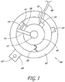
- FIG. 1 schematically illustrates an example embodiment of a reel assembly 100 for use with a closure device or system.
- the reel assembly 100 includes a housing 102, and a spool 104 that rotates relative to housing 102 to adjust tension on a lace 106.
- the spool 104 can be coupled to a first engagement member 108 and the housing 102 can be coupled to a second engagement member 110.
- the first and second engagement members 108, 110 can interface with each other to limit or otherwise influence the rotation of the spool 104 relative to the housing 102.
- the engagement members 108, 110 can allow the spool 104 to rotate substantially unimpeded in a first direction so as to gather lace 106 into the reel assembly 100, and the engagement members 108, 110, when engaged with each other, can prevent the spool 104 from rotating in a second direction that releases lace 106 from the reel assembly 100.
- the first engagement member 108 can include one or more pawls
- the second engagement member 110 can include a plurality of teeth.
- the reel assembly 100 can include a knob 112 that can be configured to control rotation of the spool 104. For example, rotating the knob 112 in a first direction can cause the spool 104 to rotate in the first direction, thereby gathering lace into the reel assembly 100. Engagement members 108, 110 can incrementally lock the spool 104 against rotation in the second direction. In some embodiments, rotating the knob 112 in a second direction can cause the engagement members 108, 110 to disengage from each other to allow the spool 104 to rotate in the second direction, thereby releasing lace 106 from the reel assembly 100.
- the engagement members 108, 110 can be configured to reengage after the spool 104 has rotated a predetermined amount in the second direction, thereby locking the spool 104 against further loosening until the knob 112 is again rotated in the second direction.
- reel assembly 100 can provide for incremental release of the lace 106 from the reel assembly 100.
- the reel 112 can include one or more drive members 114, which can be integral to, or coupled to, the knob 112, and which can interface with the spool 104, the first engagement member 108, and/or the second engagement member 110 to control rotation of the spool 104.
- a protection element 116 can be provided to increase the durability of one or both of the engagement members 108, 110.
- the protection element 116 can be a metal (or other suitably durable) cap that is placed on the portion of a pawl that interfaces with the teeth.
- the reel assembly 100 can include a debris diverter that can be configured to move debris away from the interface between the engagement members 108, 110.
- the reel assembly 100 can include a lace retaining element 120 that can be configured to retain the lace 106 away from the walls of the housing 102 to prevent the lace 106 from backing up inside the reel assembly 100.
- the lace 106 can tend to unwind inside the reel assembly 100 and move radially outward away from the rotational axis of the spool 104.
- the reel assembly 100 can include a lace termination pocket 118 that provides a termination point for the lace.
- the reel assembly 100 can include a rotation limiter 124.
- the rotation limiter can be configured to prevent the spool 104 from being rotated too far in the first direction and/or in the second direction. If excessive lace 106 is drawn into the reel assembly 100, the lace 106 can jam the reel assembly 100. If the spool 104 is rotated in the second direction when the lace 106 is fully loosened, the reel assembly 100 can start to start to gather lace 106 in the wrong direction.
- the rotation limiter can be, for example, a stop cord that is coupled to the housing 102 and to the spool 104 such that rotation of the spool 104 takes up slack in the stop cord (e.g., by winding the stop cord around a channel on the spool 104 or around a pin or other structure of the housing 102).
- the stop cord becomes tight, the spool 104 is prevented from further rotation.
- the reel assembly 100 can include a mounting member 126.
- the mounting member 126 can be a flange that is configured to be sewn, adhered, or otherwise coupled to an article (e.g., a shoe).
- the mounting member 126 can be configured to removably attach to a base member (not shown) on the article so that the reel assembly 100 can be removed from the article, such as for repair or replacement of the reel assembly 100.
- the mounting member 126 can include a hole 128 that receives a fastener (e.g., a bolt) that secures the mounting member 126 to the base member on the article.
- FIG. 2 is a perspective view of an example embodiment of a closure device or system 200.
- the closure system 200 can include a reel assembly 202, at least one lace guide 204, and a lace 206 that extends between the reel 202 and the lace guide 204.
- the reel assembly 202 can be configured to gather lace 206 to draw the lace guide 204 closer to the reel assembly 202 and tighten the closure system 200, and the reel assembly 202 can be configured to release lace 206 to loosen the closure system 200.
- any suitable number of lace guides 204 e.g., 2, 3, 5, etc.
- the lace 206 can be a highly lubricious cable or fiber having a high modulus of elasticity and a high tensile strength.
- the cable can have multiple strands of material woven together. While any suitable lace can be used, some embodiments can utilize a lace formed from extended chain, high modulus polyethylene fibers.
- SPECTRA TM fiber manufactured by Honeywell of Morris Township, N.J.
- the lace can be formed from a molded monofilament polymer.
- the lace or cable can have a diameter of at least about 0.02 inches (0.508 mm) and/or no more than about 0.04 inches (1.016 mm), or at least about 0.025 inches (0.635 mm) and/or nor more than about 0.035 inches (0.889 mm), although diameters outside these ranges can also be used.
- the lace can have a core/sheath configuration where a first material is used for the lace core and a second material is used for a sheath that is positioned over the core.
- SPECTRA TM or Dyneema ® may be used for the lace core and polyester or another material may be used for the sheath.
- the lace can be made of high modulus fibers that advantageously have a high strength to weight ratio, are cut resistant, and/or have very low elasticity.
- the lace can be formed of tightly woven fibers to provide added stiffness to the lace.
- the lace can have enough column strength that the lace can be easily threaded through the lace guides, and into the reel and spool, or through the guides so as to form a loop of lace that can be easily grasped by a user.
- the lace can have enough column strength that the lace can be pushed out of the reel without doubling back on itself, as discussed elsewhere herein.
- FIG. 3 is a perspective view of the closure system 200 incorporated into a sports shoe 208.
- the closure system 200 can also be incorporated into any other suitable articles including, but not limited to, cycling shoes, boots, other footwear, belts, hats, gloves, braces, helmets, boot bindings, backpacks, or other suitable wearable articles, or any other item in which two portions are to be selectively drawn together and loosened.
- the shoe 208 can have a first side 210a and a second side 210b, and the closure system 200 can extend between the sides 210a, 210b.
- the shoe 208 has a second reel 202' mounted to the heel portion of the shoe 208.
- the second reel 202' can be similar to, or the same as, the first reel 202.
- the second lace 206' can pass along a channel through the shoe 208 to the lace guides 204'.
- the second reel 202' can be configured to tighten a second lace 206' on an upper zone of the shoe 208, and the reel 202 can tighten a lower zone of the shoe 208.
- a single reel can be used to adjust a single lace that extends through the full set of lace guides 204, 204', or more than two reels can be used.
- a reel assembly can be mounted onto tongue of the shoe 208, or on the side or heel (as shown in FIG. 3 ), or on any other suitable portion of the article.
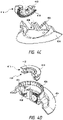
- Reel assembly 402 includes a knob 470 that may be rotated by a user to wind lace (not shown) around a spool 410 of reel assembly 402. As knob 470 is rotated, drive members (not shown) of knob 470 rotate disc 440, which in turn rotates tension control disc 420. Tension control disc 420 is coupled with disc 440 via a pair of lipped components 424 that axially extend from a top surface of disc 420 and engage with corresponding apertures 442 of disc 440.
- the components 424 may snap into the apertures 442 of disc 440 to couple the two discs, 440 and 420, together with pawl disc 430 sandwich or positioned there between. Engagement of the discs, 440 and 420, via the components 424 and apertures 442 allows rotational forces input into knob 470 to be transferred from disc 440 to tension control disc 420.
- the disc 440 and tension control disc 420 are rotatable relative to the pawl disc 430 that is sandwiched between the two discs. This configuration allows drive components 422 of the tension control disc 420 to rotate relative to pawl disc 430 and thereby engage with components of pawl disc 430 to transfer tightening and loosening rotational forces to pawl disc 430.
- Tension control disc 420 includes a plurality of drive components 422 that are used to drive and rotate pawl disc 430 in both a first direction and a second direction to tension and loosen the lace as described below.
- the tension control disc 420 may include four drive components 422 (i.e., two formed at the base of the components 424 and two independent of the components 424).
- the number of drive components corresponds with the number of pawl teeth 432 used and may be varied as desired between 1 and any number.
- drive components 422 may drive, or otherwise cause rotation of, pawl disc 430 as the tension control disc 420 is rotated via disc 440 and knob 470.
- the drive components 422 may be positioned within a space 436 between pawl teeth 432 and a drive member 434, which extends radially outward from a central core or portion of pawl disc 430.
- knob 470 is rotated in a first or tightening direction (e.g., clockwise)
- drive components 422 contact the drive members 434 and transfer rotational forces from tension control disc 420 to pawl disc 430, which causes pawl disc 430 to rotate in the first or tightening direction.
- the pawl teeth 432 may be elongated members that are cantileverly mounted to, or otherwise supported by, drive members 434 and/or pawl disc 430.
- the cantilevered configuration of pawl teeth 432 allows the pawl teeth 432 to deflect inwardly and outwardly relative to housing teeth 406 in the ratchet like fashion.
- pawl teeth 432 and housing teeth 406 allow the pawl disc 430 to be rotated in the first or tightening direction while preventing counter rotation (e.g., counterclockwise rotation) of the pawl disc 430.
- the engagement of the pawl teeth 432 and housing teeth 406 also prevents rotation of other components of the reel assembly 402, such as tension control disc 420 and spool 410.
- the engagement of the pawl teeth 432 and housing teeth 406 allows the spool 410 to be rotated in the first or tightening direction so as to wind lace (not shown) around a central channel 416 of spool 410, which tensions the lace.
- the interaction between pawl teeth 432 and housing teeth 406 also prevents counter rotation of the spool 410 to prevent unwinding of the lace from the central channel 416 of spool 410, and therefore prevents loosening of the lace.
- the rotation of spool 410 is achieved via an interaction between teeth 412 and corresponding teeth 426 of tension control disc 420.
- the respective teeth, 412 and 426, of spool 410 and tension control disc 420 extend axially from the respective components in opposite directions and are configured to mate such that rotation of tension control disc 420 in the first or tightening direction causes rotation of spool 410 in the first or tightening direction.
- the interaction between teeth 412 and teeth 426 also prevents counter rotation of spool 410, and therefore prevents unwanted loosening of the lace.
- the tension control disc 420 also enables incremental loosening of the lace when the knob 470 is rotated in a second or loosening direction (e.g., counterclockwise), which is opposite the first or tightening direction. Specifically, incremental lace tension loosening is achieved via drive components 422. Rotation of the knob 470 in the loosening direction causes tension control disc 420 to rotate in the loosening direction via disc 440 and the engagement of components 424 with apertures 442. As the tension control disc 420 rotates in the loosening direction, drive components 422 move and rotate slightly within space 436 into contact with the pawl teeth 432.
- a second or loosening direction e.g., counterclockwise
- a cammed, ramped, or sloped surface of drive components 422 "sweeps” or pushes the pawl teeth 432 out of engagement with the housing teeth 406. Stated differently, drive components 422 disengage the pawl teeth 432 from the housing teeth 406, which allow the pawl disc 430 and spool 410 to rotate in the loosening direction.
- the tension on the lace (not shown), in part, causes the spool 410 and tension control disc 420 (e.g., via teeth 412 and 426) to rotate in the loosening direction, which causes the pawl disc 430 to also rotate in the loosening direction via drive component 422.
- Rotation of the pawl disc 430 in the loosening direction causes the pawl teeth 432 to snap into engagement in a ratchet like fashion with housing teeth 406 that are adjacent the previously engaged housing teeth in the loosening direction.
- rotation of the spool 410 in the loosening direction may be achieved in incremental or discrete steps, which allows the tension of the lace to be incrementally loosened or released.
- disc 440 may include protrusions on its bottom surface that function to "sweep” or push the pawl teeth 432 out of the housing teeth 406 as described above and/or drive rotation of pawl disc 430.
- the knob 470 may be pulled axially upward relative to housing 404 in order to disengage the pawl teeth 432 from the housing teeth 406 and thereby allow spool 410 to freely spin in the second or loosening direction.
- a spring component 454 is coupled with a central bushing 450. Pulling the knob 470 axially upward causes the spring component 454 to axially move from a first annular groove or inclined face 457 of the bushing 450 to a second annular inclined face 456 of the bushing 450.
- the spring component 454 In moving from the first annular inclined face 457 to the second annular inclined face 456, the spring component 454 deflects radially outward and inward. When positioned in the second annular inclined face 456, the spring component 454 holds or otherwise maintains the knob 470, disc 440, pawl disc 430, and tension control disc 420 in an axially raised position within the housing 404 wherein the pawl teeth 432 are disengaged from housing teeth 406. In the axially raised position, the teeth 426 of tension control disc 420 may also be disengaged from the teeth 412 of spool 410. In this configuration, spool 410 is able to spin or rotate freely in the loosening direction and thereby allow the lace tension to be fully loosened or released. In other embodiments, to fully loosen or release the tension on the lace, a button, lever, or other release mechanism may be pressed or operated.
- reel assembly 402 may be coupled together via a fastening mechanism 460 (e.g., a bolt or screw) which is coupled with a central post of housing 404.
- Housing 404 may also include one or more lace channels 407 within which the lace may be threaded to access the central channel 416 of spool 410.
- the reel assembly 402 allows incremental releasing or loosening of lace tension as well as full or essentially complete releasing/loosening of the lace tension. Additional features of other reel assemblies are provided in U.S. Patent Application No. 13/273,060 , ( US 2013/0092780 A1), filed October 13, 2011 , titled "Reel-Based Lacing System".
- spool 410 To prevent rotation of the spool 410 in the loosening direction when the lace tension is at or near the tension threshold (e.g., zero lace tension), spool 410 includes teeth 414 that are positioned on and axially extend from a bottom surface of the spool 410.
- the teeth 414 interact with corresponding teeth 408 that are positioned on and axially extend from an inner bottom surface of housing 404.
- FIGs. 4C and 4D illustrate the respective teeth, 414 and 408, of spool 410 and housing 404 in greater detail.
- the teeth, 414 and 408, are configured to be disengaged until the lace tension is at or near the tension threshold.
- Disengagement of the teeth, 414 and 408, allows the spool 410 to rotate in the tightening and loosening direction as described above to tension and loosen the lace. After the teeth, 414 and 408, engage, further rotation of the spool 410 in the loosening direction is prevented or limited.
- the spool 410 is configured to move axially upward and downward relative to housing 404.
- disengagement of the teeth, 414 and 408, may be facilitated or achieved by providing a slight taper or sloped configuration on teeth 412 and teeth 426.
- the taper/slope of teeth 412 and 426 may be oriented so that the spool 410 is forced or pulled axially upward relative to housing 404 and into engagement with tension control disc 420 when the tension control disc 420 rotates in the first or tightening direction and/or some amount of lace tension exists.
- the taper/slope configuration of the teeth may cause teeth 412 of spool 410 to slide axially upward relative to and into further engagement with the teeth 426 of tension control disc 420 as the tension control disc 420 rotates in the tightening direction and/or as the lace tension is increased.
- the lace tension and sloped/tapered teeth configuration may maintain the teeth 412 and 426 in the engaged configuration as the tension control disc 420 and spool 410 are rotated in the loosening direction.
- the tension in the lace causes the spool 410 to rotate in the loosening direction, which maintains contact and engagement between teeth 412 and teeth 426 thereby keeping the spool 410 in the axially raised position with teeth 414 and 408 disengaged.
- the amount of force or pressure exhibited between the teeth 412 of spool 410 and the teeth 426 of tension control disc 420 corresponds to the tension in the lace at any given time.
- the force or pressure between the teeth 412 and 426 also decreases and nears zero, which allows the spool 410 to begin to move axially downward relative to tension control drive 420 and housing 404.
- the spool 410 will move axially downward relative to housing 404 so that the teeth 414 of spool 410 engage with the teeth 408 of housing 404. Frictional engagement of the teeth, 414 and 408, prevents or limits further movement of spool 410 in the loosening direction. As the knob 470 and tension control disc 420 are rotated in the loosening direction after engagement of teeth 414 and 408, a rear surface of teeth 426 of tension control disc 420 will contact a rear surface of the teeth 412 of spool 410.
- the rear surfaces of teeth 426 and 412 are sloped or ramped so that contact between the rear surfaces of the teeth, 426 and 412, presses or forces the spool 410 axially downward relative to housing 404, which increases the frictional contact between teeth 414 and 408 and prevents further rotation of spool 410 in the loosening direction.
- the sloped the ramped configurations of teeth 426 and 412 also allows the tension control disc 420 and teeth 426 to slide axially up and over the teeth 412 and spool 410 as the tension control disc 420 is rotates in the loosening direction.
- knob 470 may continue to be rotated in the loosening direction without causing rotation of the spool 410.
- the knob 470 and/or other components may move slightly axially upward and downward as the tension control disc 420 slides axially up and over the spool teeth 412.
- the knob 470 may be forced axially upward and into an open configuration when the knob 470 is rotated in the loosening direction after engagement of teeth 414 and 408.
- the central bushing 450 may engage and lock or maintain the knob 470 in an axially upward and open configuration when the knob 470 is rotated in the loosening direction after engagement of teeth 414 and 408.
- the spool 410 in the open configuration, may be allowed to freely spin within the housing 404.
- the teeth, 414 and/or 408, may be replaced by other frictional components, such as a rubber type gasket or material, abrasive materials, tacky materials, and the like. Even when the spool 410 is moved axially downward so that the teeth, 414 and 408, contact one another, the configuration of the teeth 426 of tension control disc 420 and the teeth 412 of spool 410 is such that rotation of the tension control disc 420 in the tightening direction causes the teeth 426 and 412 to contact one another and reengage.
- other frictional components such as a rubber type gasket or material, abrasive materials, tacky materials, and the like.
- the teeth 426 of disc 420 and the teeth 412 of spool 410 are configured in an axially overlapping manner so that rotation of the knob 470 and tension control disc 420 causes the teeth 426 and 412 to contact one another as long as the knob 470 and other reel assembly components are not in the axially raised position relative to housing 404.
- the teeth 426 of tension control disc 420 will once again engage the teeth 412 of spool 410, which will cause the spool 410 to be forced or pulled axially upward and thereby disengage the teeth 414 and 408 of the spool 410 and housing 404, respectively.
- the reel assembly 402 may be operated to re-tension the lace as previously described.
- a single "active" lace may traverse across a shoe or other article and may be tensioned by any of the incremental lace loosening closure devices described herein.
- the term single active lace means that a single lace is coupled with the closure device and tensioned thereby.
- Such laces often have a distal end that terminates on the shoe or article, or on a housing or other component of the closure device, and a proximal end that is coupled with the closure device (e.g., wound around a spool component) and tensioned by the closure device.
- a dual active lace may traverse the shoe or other article and may be tensioned by an incremental lace loosening closure device.
- the term dual active lace means that two or more laces are coupled with the closure device and tensioned thereby, or that a proximal and distal end of a single lace are coupled with the closure device and tensioned thereby.
- the two or more laces may each have a distal end that terminates on the shoe or article, or on a housing or other component of the closure device, and a proximal end that is coupled with the closure device and tensioned thereby.
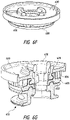
- FIG. 4E illustrates the reel assembly 402 with the spool 410 fully engaged with tension control disc 420.
- the teeth 414 of spool 410 are disengaged from the teeth 408 of housing 404 such that a gap exists between the teeth 408 and 414.
- the teeth 426 of tension control disc 420 are fully engaged with the teeth 412 of spool 410 such that the spool 410 is pulled or forced axially upward and into full engagement with tension control disc 420.
- spool 410 is able to be rotated in both the tightening and loosening direction to incrementally tension and/or loosen lace (not shown) of reel assembly 402.
- FIG. 4F illustrates the reel assembly 402 with the knob 470 and other components (i.e., pawl disc 430, tension control disc 420, and disc 440) raised axially relative to housing 404 such that pawl teeth 432 are disengaged from the housing teeth 406 and such that teeth 412 and 426 of spool 410 and tension control disc 420, respectively, are disengaged.
- the spool 410 is able to freely rotate in the loosening direction to fully release or loosen the tension of the lace of reel assembly 402.
- FIG. 4G illustrates the reel assembly 402 with the teeth 408 of housing 404 fully engaged with the teeth 414 of spool 410.
- FIG. 4G also illustrates the back surfaces of teeth 412 and 426 contacting one another such that the spool 410 is forced or pressed axially downward to increase the frictional contact between teeth 408 and 414 and thereby prevent rotation of spool 410 in the loosening direction.
- FIG. 4G further illustrates the teeth 412 and 426 sliding axially up and over one another as the knob 470 and tension control disc 420 are rotated in the loosening direction.
- the knob 470, tension control disc 420, and/or other components may move slightly axially upward and downward as teeth 426 slide up and over spool teeth 412.
- a spring mechanism e.g., spring washer and the like - (not shown) may be positioned between the spool 410 and the tension control disc 420 to provide an axially downward force on the spool 410.
- the axially downward force provided by the spring mechanism may cause the spool 410 to move axially downward while some amount of tension remains in the lace.
- the angle or taper of the teeth 412 and the teeth 426 of the tension control disc 420 may be adjusted or decreased so that engagement of the teeth does not aggressively pull the spool 410 axially upward.
- the angle or taper of the teeth 412 and teeth 426 may be 10 degrees or less, 5 degrees or less, and the like, as measured from a plane parallel to an axis of the spool to allow the teeth 412 and the teeth 426 to easily disengage via the spring mechanism.
- the teeth 408 and 414 of housing 404 and spool 410, respectively may engage with one another to prevent further rotation of spool 410 while some amount of tension remains in the lace.
- This arrangement may keep or maintain a relatively tight wind of the lace about the spool 410 so as to prevent kinking, buckling, entangling, or other lace issues from occurring within housing 404.
- This arrangement may also prevent a user from fully loosening the lace tension to prevent the user from removing an article from a limb, such as a brace.
- Such embodiments may be employed to ensure that a minimum amount of tension remains in the lace to ensure, for example, that a brace or other article is being worn properly.
- a physician may prescribe a minimum fit or brace pressure for a patient and the closure system may be used to ensure that the patient never loosens the brace beyond the prescribed minimum fit.
- the spring mechanism may be varied to provide a desired amount of axial force on spool 410.
- a relatively flexible spring mechanism may be used when a small axial force is desired, or a relatively stiff spring mechanism may be used when a large axial force is desired.
- An intermediate spring stiffness may likewise be used when an intermediate axial force is desired.
- reel assembly 502 is similar to reel assembly 402 in that reel assembly 502 includes a housing 504, knob 570, spool 510, disc 540, tension control disc 520, and pawl disc 530.
- Rotation of the knob 570 causes disc 540, pawl disc 530, and tension control disc 520 to rotate as described above.
- the pawl teeth 532 of pawl disc 530 interact with housing teeth 506 of housing 504 to hold the spool 510 in place as described above.
- the spool 510 is configured to move axially upward and downward within housing 504 such that a stop mechanism (i.e., teeth 514 and 508 of housing 504 and spool 510, respectively) engage and disengage to limit counter-rotation of the spool 510 as previously described.
- a stop mechanism i.e., teeth 514 and 508 of housing 504 and spool 510, respectively
- the spool teeth 512 are also angled as previously described to allow the teeth 526 of tension control disc 520 to deflect axially upward and over the spool teeth 512 when teeth 514 and 508 are engaged.
- the various other components of reel assembly 502 e.g., components 560, 550, 554, 542, 534, 522, 524, and 516) may function similar to the corresponding component of reel assembly 402.
- reel assembly 502 includes a spring washer 552 that is positioned between the spool 510 and tension control disc 520 and that functions to bias the spool 510 axially downward and into engagement with the stop mechanism (i.e., biases engagement of teeth 514 and 508).
- the spring washer 552 allows the stop mechanism to be engaged at a lace tension threshold that may be substantially greater than zero.
- the use of the spring washer 552 may be important in medical brace applications and/or to further ensure that the lace and/or internal components of reel assembly 502 are protected.
- the reel assembly 502 may not configured to allow a user to pull axially upward on knob 570 to disengage the spool teeth from the housing teeth and thereby allow the spool 510 to freely rotation within housing 504 to fully loosen the lace. Rather, the spool teeth and housing teeth of reel assembly 500 may always be engaged such that tensioning and loosening of the lace is achieved by rotation and counter-rotation of the knob 570.
- the lace loosening device or system is capable of providing essentially infinite lace loosening increments, steps, or amounts.
- the lace loosening system of FIGs. 6A-G allows micro-adjustments of lace tension to be made.
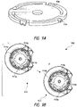
- the system includes a reel assembly 600 having a tensioning mechanism or knob 604 that is rotatable by the user in a tightening and loosening direction to tension and loosen the lace as desired.
- the knob 604 includes a tension release mechanism that is configured to allow a spool 610 to be rotated in a first direction via a first operation of the knob 604 to incrementally tension the lace and to allow the spool 610 to be rotated in a second direction via a second operation of the knob 604 such that the tension member's tension is releasable in substantially infinitely small increments.
- the tension release mechanism includes a first clutch component or disc 620 that couples with a second clutch component or disc 608.
- the second disc 608 is in turn coupled with the spool 610 around which the lace is wound.
- a pawl disc 606 is positioned between the first disc 620 and the second disc 608.
- the components fit within an interior region of housing 602.
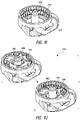
- FIG. 6G illustrates the assembled components of reel assembly 600 without the housing 602.
- the first disc 620 and the second disc 608 are axially aligned and frictionally engageable so that a first operation of the knob 604 (i.e., rotation of the knob in the tightening direction) frictionally engages the first disc 620 and the second disc 608 to allow the spool to be rotated in the first direction and so that a second operation of the knob 604 (i.e., rotation of the knob in the loosening direction) disengages the first disc 620 and the second disc 608 to allow the spool 610 to be rotated in the loosening direction.
- a first operation of the knob 604 i.e., rotation of the knob in the tightening direction
- a second operation of the knob 604 i.e., rotation of the knob in the loosening direction
- the spool 610 is allowed to rotate in the loosening direction until rotation of the knob 604 in the loosening direction is ceased whereupon the first disc 620 reengages with the second disc 608 if the lace's tension is greater than a tension threshold (e.g., near zero tension).
- a tension threshold e.g., near zero tension
- the tension release mechanism i.e., first disc 620 and second disc 608 may also be configured to prevent the lace's tension from being loosened via rotation of the knob 604 in the loosening direction after the lace's tension achieves or decreases beyond the tension threshold.
- the pawl disc includes pawl teeth 607 that interact with housing teeth 612 of housing 602 as described herein to allow the spool 610 to be wound in the tightening direction and to prevent unwinding of the spool 610 in the loosening direction.
- the spool 610 includes spool teeth 614 that interact with teeth 616 positioned on the bottom surface of the second disc 608. Engagement of the teeth 616 and 614 prevent the spool 610 from rotating in the loosening direction.
- the first disc 620 includes a central protrusion that extends axially downward.
- the central protrusion includes cam surfaces 622 that interact with cam surfaces 624 of an axially upward extending protrusions of second disc 608.
- the cam surfaces, 622 and 624 are oppositely ramped or angled such that rotation of the first disc 620 in the tightening direction relative to second disc 608 causes the ramped or angled surfaces to slide into frictional engagement, or to increase frictional engagement, which pulls the second disc 608 axially upward relative to first disc 620, or vice versa.
- Rotation of the first disc 620 in the loosening direction relative to the second disc 608 causes the ramped or angled surfaces to slide out of frictional engagement, or decreases frictional engagement, which allows the second disc 608 to move axially downward relative to first disc 620, or vice versa.
- first disc 620 fit axially under the cam surfaces 624 of second disc 608.
- cam surfaces 622 slide relative to cam surfaces 624 to increase the frictional engagement or contact between the two components, which pulls the second disc 608 axially upward relative to first disc 620.
- Movement of the second disc 608 axially upward relative to first disc 620 compresses or pinches the pawl disc 606 between the first disc 620 and second disc 608 as shown in FIG. 6F , which locks or maintains the discs (i.e., the first disc 620, second disc 608, and pawl disc 606) in position.
- the pawl disc 606 is rotationally maintained or locked in place relative to housing 602 via the interaction between the pawl teeth 607 and the housing teeth 612.
- the spool 610 is maintained or locked in rotational position relative to the housing 602 via the pressed or pinched pawl disc 606 and the interaction between the spool teeth 614 and the teeth 616 of second disc 608. In this manner, the components of reel assembly 600 are held in rotational position relative to the housing 602 and counter-rotation (i.e., rotation in the loosening direction) is prevented.
- the cam surfaces 622 and 624 begin to frictionally disengage, which allows the second disc 608 to move axially downward and loosens the compressive pressure exerted on the pawl disc 606.
- the second disc 608 becomes frictionally unlocked from the pawl disc 606 and is able to slip or rotate in the loosening direction, which allows the lace tension to be loosened.
- the lace will cause the spool 610 to rotate in the loosening direction, which causes the second disc 608 to also rotate in the loosening direction.
- Rotation of the second disc 608 in the loosening directions causes the cam surfaces 624 to rotate relative to the cam surfaces 622 of first disc 620 thereby frictionally reengaging the cam surfaces 624 and 622 and discs 620 and 608.
- This reengagement of the cam surfaces, 624 and 622, and the respective discs, 608 and 620 recompresses the pawl disc 606 and locks the discs in position, thereby preventing further counter-rotation of the discs.
- the slippage of the second disc 608 relative to first disc 620 may be relatively instantaneous such that a user is unable to detect or otherwise notice the slippage of the second disc 608.
- the frictional re-engagement of the first disc 620 and second disc 608 may be unnoticeable or undetectable by the user such that as the user stops counter rotation of the knob 604 (i.e., rotation of the knob 604 in the loosening direction), the user may be unable to detect or notice any additional movement of the second disc 608 or any other internal component. Rather, the user may believe that rotation of the knob 604 in either the tightening or loosening direction results in immediate rotation of the second disc 608 and spool 610 corresponding to an immediate tensioning or loosening of the lace.
- the reel assembly 600 provides essentially an infinite amount and relatively precise lace loosening adjustment. Stated differently, a user may counter rotate the knob 604 by essentially infinitely small increments, degrees, or amounts, which causes loosening of the lace by correspondingly small increments, degrees, or amounts.
- the tension release mechanism (i.e., first disc 620 and second disc 608) of reel assembly 600 allows the spools 610 to be releaseably locked in any angular orientation within the housing upon cessation of counter-rotation of the knob 604. This allows the lace's tension to be loosened or released in substantially infinitely small increments as described above.
- cam surfaces 622 may be directly incorporated with the knob 604 rather than being included on a separate disc 620.
- the second disc 608 may be incorporated with the spool 610 rather than using separate components.
- Other components of reel assembly 600 may likewise be integrated to reduce the overall component count.
- the reel assembly 600 may include a stop mechanism that prevents rotation of the spool 610 in the loosening direction after the lace's tension achieves or decreases beyond a tension threshold.
- a bottom surface of the spool 610 includes teeth 626 that extend axially downward from a bottom surface of the spool 610.
- the teeth 626 may engage with corresponding teeth 628 that extend axially upward from an inner surface of the housing 602 to prevent or restrict rotation of the spool 610 in the loosening direction after the lace's tension achieves or decreases beyond a tension threshold.
- the spool 610 may move axially upward and downward to engage and disengage the stop mechanism (i.e., engage and disengage teeth 626 and 628).
- the cam surfaces 622 and 624 may be configured to skip over or relative to one another.
- engagement of the teeth 626 and 628 may prevent further rotation of the knob 604 in the loosening direction.
- the reel assembly 600 may also include a full release mechanism that is transitionable between an engaged state and a disengaged state.
- the full release mechanism may include a bushing 630 and spring component 640 as previously described that transition between the engage state and the disengaged state when the knob 604 is pulled axially upward or pushed axially downward relative to housing 602.
- the knob 604 when the full release mechanism is in the engaged state (i.e., positioned axially downward relative to housing 602), the knob 604 may be rotated to tension or loosen the lace.
- the full release mechanism is in the disengaged state (i.e., positioned axially upward relative to housing 602), the lace's tension may be automatically and/or fully loosened or released.
- the pawl disc 606 may be configured to fit around the cam surface 624 of second disc 608. This configuration may allow the first disc 620 and second disc 608 to more easily compress the pawl disc 606 and/or allow greater compressive pressures to be exerted on the pawl disc 606.
- FIGs. 7A and 7B illustrated is an incremental lace loosening system, not covered by the present invention.
- FIGs. 7A and 7B illustrate a reel assembly 700 having a knob 702 that is rotatable by a user as described herein.
- the knob 702 couples with a drive disc 704 that is rotated as the user rotates knob 702.
- the drive disc 704 may include a plurality of apertures 712 through which corresponding shafts 710 of the knob 702 are inserted in order to drive rotation of disc 704 via rotation of knob 702.
- Drive disc 704 in turn is used to drive spool 706 in both the tightening and loosening direction.
- Drive disc 704 includes gear teeth or cogs 705 that fit within recesses 703 of spool 706 in order to drive spool 706.
- a profile of the outer surface 707 of spool 706 corresponds to a profile of the outer surface 709 of drive disc 704 such that during rotation of the drive disc 704 while the teeth 705 and recesses 703 are disengaged, the outer surface 709 of drive disc 704 slides along the outer surface 707 of spool 706.
- the configuration of the outer surfaces, 707 and 709, of the spool 706 and drive disc 704, respectively, prevents rotation of the spool 706 in the loosening direction because any such rotation causes the outer surface 707 of the spool 706 to contact the outer surface 709 of the drive disc 704. In this manner, the spool 706 and drive disc 704 are essentially locked in place by the configuration of the outer surfaces, 707 and 709, of the components.
- FIGs. 7A and 7B provide a silent tightening/loosening mechanism that generally requires less parts than other tightening mechanisms.
- the system also allows for very small incremental tightening/loosening steps, which allows for precise lace tensions to be achieved.
- FIG. 8 illustrated is a device or system, not covered by the present invention, that allows the lace tension to be incrementally loosened.
- FIG. 8 illustrates a reel assembly 800 having a pawl disc 806 that is positioned within a housing 802 as described herein such that the pawl teeth 807 of pawl disc 806 interact with the housing teeth 804 of housing 802 to prevent counter rotation of the spool (not shown).
- reel assembly 800 includes a plurality of sweeper arms 808 that are coupled with a knob (not shown) of reel assembly 800.
- the tension will cause the spool (not shown) to counter rotate (i.e., rotate in the loosening direction), which will cause the pawl disc 806 to also counter rotate. Counter rotation of the pawl disc 806 will cause the pawl teeth 807 to become disengaged from the sweeper arms 808 and to radially deflect outward and into contact with the housing teeth 804 (image 4). If tension does not exist within the reel assembly's lace, the spool and pawl disc 806 will not counter rotate. Rather, the spool and pawl disc 806 will remain in relatively the same position engaged with the sweeper arms 808.
- the lace may be loosened only while essentially some amount of tension remains in the lace, which may prevent some of the lace loosening problems identified above.
- the sweeper arms 808 will remain engaged with the housing teeth 804 until the knob (not shown) is released or rotated slightly in the tightening direction. In this manner, the incremental loosening of the lace is achieved via back-and-forth rotation of the reel assembly's knob.
- the knob may be biased so as to disengage the sweeper arms 808 from the housing teeth 804 upon a user releasing the knob.
- FIGs. 9A-K illustrated are incremental lace loosening systems or devices, not covered by the present invention, in which pressing a knob or button causes the lace tension to be incrementally loosened.
- FIGs. 9A-C illustrate a reel assembly 900 wherein pressing the knob 904 axially downward relative to the housing 902 causes the pawl teeth 914 of pawl disc 906 to be temporarily disengaged from the housing teeth 912 of housing 902.
- the pawl teeth 914 have a chamfered or angled upper surface that is engaged by an axially downward extending protrusion 916 of knob 904.
- the downward extending protrusion 916 includes a chamfered or angled bottom surface that contacts the chamfered or angled upper surface of pawl teeth 914 to causes the pawl teeth 914 to deflect radially inward and out of engagement with the housing teeth 912 upon depression of the knob 904 axially downward relative to housing 902.
- Disengagement of the pawl teeth 914 from the housing teeth 912 causes the spool (not shown) and pawl disc 906 to rotate in the loosening direction as long as some amount of tension remains in the lace.
- Rotation of the pawl disc 902 in the loosening direction causes the pawl teeth 914 to become disengaged from the protrusion 916 of knob 904, which causes the pawl teeth 914 to deflect radially outward and into engagement with the housing teeth 912. In this manner, incremental loosening of the lace is achieved each time the knob 904 is pressed axially downward.
- the pawl disc 906 may include a pair of teeth that are always engaged with the housing teeth 912 and a pair of teeth that are always disengaged from the housing teeth 912.
- a first pair of pawl teeth 914a may be engaged with the housing teeth 912 while a second pair of pawl teeth 914b is disengaged from the housing teeth 912.
- the pairs of housing teeth, 912a and 912b may be configured such that the pairs of teeth are a half step off from one another, or in other words so that the non-engaged pair of teeth is halfway engaged with the housing teeth 912.
- the knob 904 may be configured so that the protrusions 916 are always positioned axially above the pair of teeth (i.e., initially pawl teeth 914a) that are engaged with the housing teeth 912. Depression of the knob 904 causes the engaged pair of teeth 914a to disengage from housing teeth 912, which causes counter rotation of the pawl disc 906 as described above. As the pawl disc 906 counter-rotates, the previously disengaged teeth 914b will engage with the housing teeth 914 while the previously engaged teeth 914a remain disengaged from housing teeth 912. In this manner, depression of the knob 904 will cause the lace to be loosened in half steps increments.
- the half step increments may also help reduce the impact of the pawl teeth during engagement with the housing teeth, which may increase the life of the pawl teeth and reel assembly.
- the knob 904 may rotate after each depression so that the protrusions 916 are always positioned axially above the pair of teeth that are engaged with the housing teeth 912.
- FIGs. 9D-H illustrated is an incremental lace loosening system, not covered by the present invention, where depression of a button causes incremental loosening of the lace.
- the system of FIGs. 9D-H includes a housing 930 that is similar to the reel assembly housings previously described.
- housing 930 includes lace ports 938 within which the lace enters and exits the housing 930.
- housing 930 does not include housing teeth that are rigidly coupled with an interior space of the housing 930. Rather, a toothed ring or disc 940 is positioned within a cylindrical inner surface 933 of housing 930.
- the toothed ring 940 is configured to be rotatable within the cylindrical inner surface 933 of housing 930 rather than rigidly coupled therewith.
- the toothed ring 940 includes a plurality of teeth 942, which are configured to interact with pawl teeth (not shown) of a pawl disc (not shown) as previously described to prevent counter rotation of the pawl disc and a spool (not shown).
- a button mechanism 950 is coupled with housing 930 to prevent rotation of the toothed ring 940.
- housing 930 includes a recess or channel 934 within which the button mechanism 950 is positioned.
- a pin 958 is inserted within an aperture 935 of the channel 934 and through a corresponding aperture 957 of button mechanism 950. Pin 958 pivotably couples the button mechanism 950 within channel 934.
- Button mechanism 950 includes a pressable portion 952 and two protrusions 954 and 956 that are positioned on opposite ends of the button mechanism 950.
- FIG. 9H which is a top cross sectional view taken along plane A-A of FIG. 9G
- the button mechanism 950 pivots within channel 934 via radially pressing of portion 952, one of the protrusions, 954 or 956, pivots radially through an aperture or window of housing 930 and into the cylindrical inner surface 933 while the other protrusion, 954 or 956, pivots radially outside of the cylindrical inner surface 933.
- Radially pressing portion 952 of button mechanism 950 causes the protrusions, 954 and 956, to displace radially into and out of the inner cylindrical surface 933 of housing 930.
- the toothed ring 940 includes a plurality of apertures or recesses 946 within which the protrusions, 954 and 956, of button mechanism 950 are positionable. As long as one of the protrusions, 954 or 956, is positioned within one of the recesses 946 of the toothed ring 940, the toothed ring 940 will be prevented from rotating. Radially pressing the portion 952 of button mechanism 950 to pivot the protrusions, 954 and 956, however, will allow the toothed ring 940 to temporarily rotate in the loosening direction. For example, as shown in FIG.
- protrusion 954 in a first state protrusion 954 is positioned within one of the recesses 946 of toothed ring 940 while protrusion 956 is displaced outside of the recesses 946. Depressing the portion 952 causes button mechanism 950 to pivot such that protrusion 954 is pivoted out of the recesses 946 while protrusion 956 is pivoted into another recesses 946.
- the protrusions, 954 and 956, are configured so that as the protrusions pivot into and out of the recesses 946, the toothed ring 940 incrementally rotates in the loosening direction. For example, as protrusion 956 is pivoted within a recess 946, the toothed ring 940 will rotate slightly in the loosening direction before a wall of the recess 946 contacts the protrusion 956. Similarly, as protrusion 954 is pivoted within a recess 946, the toothed ring 940 will rotate slightly in the loosening direction before a wall of the recess 946 contacts protrusion 954.
- the button mechanism 950 may include a spring 955, or other biasing mechanism, that biases the button mechanism 950 toward the first state with protrusion 954 positioned within a recess 946. Stated differently, as a user releases portion 952, the button mechanism 950 may automatically pivot so that protrusion 954 is positioned within a recess 946. In this manner, a user may merely press and release portion 952 of button mechanism 950 to cause incremental loosening of the lace.
- the toothed ring 940 is able to rotate in the loosening direction, the pawl disc (not shown), spool (not shown), and/or other components (e.g., knob and the like) that are coupled with the toothed ring 940 are also able to rotate.
- Rotation of the toothed ring 940 in the loosening direction is actuated by lace tension.
- lace tension when the lace tension is essentially fully loosened or released, counter-rotation of the toothed ring 940 and other reel assembly components with be prevented or limited.
- a counter-rotational force is transmitted to the spool and any components coupled therewith, such as the toothed ring 940.
- the counter-rotational force that is transmitted to the toothed ring 940 via the lace tension and spool will cause the toothed ring to counter rotate as the portion 952 is pressed. In this manner, the toothed ring 940 and spool will only rotate as long as some level of tension exists within the lace and will not rotate when the lace tension is fully loose or released.
- housing 972 includes a first level of housing teeth 976 and a second level of housing teeth 974 that is positioned axially above the first level of housing teeth 976.
- housing 972 includes a first level of housing teeth 976 and a second level of housing teeth 974 that is positioned axially above the first level of housing teeth 976.
- the pawl disc 980 is pressed axially downward relative to the housing 972
- the pawl teeth 982 are forced from the second level of housing teeth 974 into the first level of housing teeth 976.
- the pawl teeth 982 are forced from the first level of housing teeth 976 into the second level of housing teeth 974.
- the levels of housing teeth, 976 and 974 are arranged such that each movement from one level of housing teeth to the other level of housing teeth causes an incremental counter-rotation of the pawl disc 980 and any components coupled therewith (e.g., the spool, knob, and the like) in the loosening direction.
- Each movement between housing teeth levels may cause a half step rotation - or in other words, may cause the pawl disc 980 to rotate approximately 1 ⁇ 2 the circular pitch of the housing teeth.
- the pawl teeth 982 may be initially engaged with the second housing teeth 974.
- the pawl disc 980 may be moved axially downward relative to housing 972 so that the pawl teeth 982 engage with the first housing teeth 976 and the pawl disc 980 rotates a half step in the loosening direction. As shown in 994 of FIG. 9K , the pawl disc 980 may then be moved axially upward relative to housing 972 so that the pawl teeth 982 reengage with the second housing teeth 974 and the pawl disc 980 again rotates a half step in the loosening direction.
- the pawl disc 980 may be moved axially downward and/or upward by pressing on and releasing the reel assembly's knob (not shown). Further, the pawl disc 980 may be biased toward the second housing teeth level 974 so that upon release of the reel assembly's knob, the pawl disc 980 automatically adjust axially upward into engagement with the second housing teeth level 974. In this manner, a user may effectuate incremental loosening of the lace tension by repeatedly pressing on the reel assembly's knob.
- incremental loosening of lace tension can be achieved via the lace guides in addition using the reel assembly.
- the lace guides may be adjusted so as to incrementally decrease the tension on the lace, or the system may include an additional component that may be adjusted to incrementally loosen the tension on the lace.
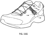
- FIGs. 10A-11I illustrate various embodiments of lace guides that may be used to incrementally loosen tension on the lace.
- the lacing system 1000 includes a reel assembly 1002 that is operated as described herein to tension lace 1004.
- the lace 1004 is wound around a plurality of guides (i.e., guides 1006, 1007, and 1008) that direct the lace 1000 along a lace path of the lacing system 1000.
- the lacing system 1000 includes a plurality of guide systems positioned longitudinally along the lace path. Each guide system includes a first end guide 1006, a second end guide 1008, and an intermediate guide 1007 that is positioned between the first end guide 1006 and the second end guide 1008. Each guide system redirects the lace 1004 from a first direction to a second direction.
- the intermediate guide 1007 is adjustable so as to incrementally loosen the tension on the lace by varying the lace path of the guide system.
- the intermediate guide 1007 functions similar to a cam component to engage and disengage the lace 1004 and thereby affect the lace path and tension.
- the intermediate guide 1007 may pivot between a first position (i.e., 1 of FIGs. 10A-C ) in which the intermediate guide 1007 engages the lace 1004 and a second position (i.e., 2 of FIGs. 10A-C ) in which the intermediate guide 1007 disengages the lace 1004.
- the intermediate guide 1007 engages the lace 1004 in the first position, the overall lace path is longer and the tension in the lace 1004 is increased as the lace 1004 slightly stretches and/or the laced article (e.g., a shoe) is closed more tightly.
- the intermediate guide 1007 does not engage the lace 1004 in the second position, the overall lace path is shorter and the tension in the lace 1004 is decreased as the lace 1004 relaxes and/or the laced article (e.g., a shoe) is slightly opened.
- the above scenario assumes that the overall lace length in the system remains unchanged. Stated differently, the above scenario assumes that no lace is added or removed as the intermediate guide 1107 is adjusted.
- the intermediate guide 1007 may engage a stop member 1009 when the intermediate guide 1007 is positioned in the first position.
- the stop member 1009 may prevent the intermediate guide 1007 from rotating out of the first position, in which the intermediate guide 1007 engages the lace 1004.
- the intermediate guide 1007 may also be positioned such that the pressure exerted on the intermediate guide 1007 from the lace 1004 presses or maintains the intermediate guide 1007 in contact or engagement with the stop member 1009.
- the intermediate guide 1007 may be positioned slightly off center from a pivot of the intermediate guide 1007 such that the lace tension biases the intermediate guide 1007 to rotate toward and/or into engagement with the stop member 1009.
- intermediate guide 1007 Since the intermediate guide 1007 is biased slightly toward the stop member 1009, rotation of the intermediate guide 1007 away from the stop member 1009 may cause the tension in the lace to slightly increase before the intermediate guide 1007 is disengaged from the lace 1004 to decrease the lace tension.
- the intermediate guide 1007 may include a tab 1005 that is grippable by a user to aid in rotating the intermediate guide 1007 away from the stop member 1009.
- the tab 1005 may allow a user to easily place a thumb or finger atop the intermediate guide 1007 and rotate the intermediate guide 1007 away from the stop member 1009.
- the intermediate guide 1007 may include an internal spring (not shown) that biases the intermediate guide 1007 toward the stop member 1009 when tension is loosened from the lace 1004. In such embodiments, when the tension on the lace 1004 is fully loosened or released, the internal spring may cause the intermediate guide 1007 to pivot into engagement with the stop member 1009.
- the intermediate guides 1007 of the lacing system 1000 may return to the first position so that upon re-tensioning of the lace 1004 via reel assembly 1002, the intermediate guides 1007 may be used to incrementally loosen the lace 1004.
- one or more of the guide systems may not include an intermediate guide 1007.
- guide systems positioned closer to a user's toe may not include an intermediate guide 1007 while guide systems positioned closer to the user's ankle or heel do include the intermediate guides.
- Such systems may allow the user to easily adjust the lace tension by placing the intermediate guides 1007 in areas that are more easily accessible to the user.
- lacing system 1010 that includes an adjustable guide 1016 that may be used to incrementally loosen tension on the lace.
- the lacing system 1010 includes one or more of the adjustable guides 1016 and/or one or more reel assemblies 1012. As shown in FIGs. 10D and 10E , the adjustable guides 1016 may be positioned laterally across from a reel assembly 1012 and/or may include one or more non-adjustable lace guides 1018. In other embodiments, lacing system 1010 may include a single reel assembly 1012 and a combination of adjustable guides 1016 and/or non-adjustable guides 1018.
- the adjustable guide 1016 may have a non-circular profile or surface (e.g., oblong or oval configuration) such that rotation of the adjustable guide 1016 relative to the lace 1014 alters the lace path by affecting the contact or engagement of the guide 1016 with the lace 1014.
- the guide 1016 may function similar to a cam component to affect the lace path and tension.
- a first position position C
- the adjustable guide 1016 may be rotated such that a large area or cam surface of the adjustable guide 1016 engages or contacts the lace 1014 and increases the lace path.
- the adjustable guide 1016 may engage the lace 1014 by a maximum amount.
- the path of the lace 1014 may be fully extended so that the tension on the lace 1014 is at or near a maximum tension.
- the adjustable guide 1016 may be rotated to a second position (position B), such that a smaller area or cam surface of the adjustable guide 1016 engages or contacts the lace 1014, or stated differently, so that the adjustable guide 1016 engages the lace 1014 by an amount less than position C.
- position B the path of the lace 1014 may be decreased compared with position C so that the tension on the lace 1014 is decreased.
- the adjustable guide 1016 may again be rotated to a third position (position A), such that a smallest cam area or surface of the adjustable guide 1016 engages or contacts the lace 1014.
- the adjustable guide 1016 may engage the lace 1014 by a minimal amount. In this position (i.e., position A), the path of the lace 1014 may be minimal so that the tension on the lace 1014 is at or near a minimum tension.
- each guide 1016 may be adjusted between positions A-C to vary the overall tension in the lace 1014.
- a method for configuring a reel for use with a lacing system for tightening an article, not covered by the invention may include providing a housing having an interior region and positioning a spool within the interior region of the housing so that the spool is rotatable relative to the housing.
- the spool may have an annular channel formed therein.
- the method may also include operably coupling a knob with the spool to cause the spool to rotate within the interior region of the housing upon rotation of the knob.
- the knob may be rotatable relative to the housing so that 1) incremental rotation of the knob in a first direction causes a corresponding incremental rotation of the spool within the interior region of the housing that incrementally gathers a tension member in the annular channel formed in the spool and 2) incremental rotation of the knob in a second direction causes a corresponding incremental rotation of the spool that incrementally releases the tension member from the annular channel formed in the spool.
- the method may also include configuring the reel with a stop mechanism that is configured to prevent rotation of the spool in the second direction when a tension of the lace achieves or decreases beyond a tension threshold.
- the stop mechanism may be configured to engage only when the tension of the lace achieves or decreases beyond the tension threshold and engagement of the stop mechanism may prevent the spool from rotating in the second direction.
- the spool may be axially moveable within the interior region of the housing and axial movement of the spool within the interior region may effect engagement and disengagement of the stop mechanism.
- the stop mechanism is moveable between an engaged state and a disengaged state. In such instances, the stop mechanism may be configured to move into the engaged state only when the tension of the lace achieves or decreases beyond the tension threshold and may be configured to move into the disengaged state upon rotation of the knob in the first direction.
- the stop mechanism includes teeth, a rubber gasket, an abrasive material, a tacky material, and the like.
- the stop mechanism includes a first set of teeth that are positioned on a bottom surface of the interior region of the housing and a second set of teeth that are positioned on a bottom flange of the spool.
- the spool is axially moveable within the interior region of the housing so that when the lace tension achieves or decreases beyond the tension threshold, the spool moves axially downward within the interior region of the housing to engage the first set of teeth and the second set of teeth and thereby prevent rotation of the spool in the second direction.
- the method may further include configuring the reel with a release mechanism that, upon actuation, enables the tension member to be automatically released from the annular channel formed in the spool by allowing free rotation of the spool in the second direction.
Description
- The present invention is related to closure systems for various articles, such as braces, medical devices, shoes, clothing, apparel, and the like. Such articles typically include closure devices that allow the article to be placed and closed about a body part. The closure devices are typically used to maintain or secure the article to the body part. For example, shoes are typically placed over an individual's foot and lace is tensioned and tied to close the shoe about the foot and secure the shoe to the foot. Conventional closure devices have been modified in an effort to increase the fit and/or comfort of the article about the body part. For example, shoe lacing configurations and/or patterns have been modified in an attempt to increase the fit and/or comfort of wearing shoes. Conventional closure devices have also been modified in an effort to decrease the time in which an article may be closed and secured about the body part. These modifications have resulted in the use of various pull cords, straps, and tensioning devices that enable the article to be quickly closed and secured to the foot.
WO 2010/059989 A2 discloses a lacing system configured to selectively adjust the size of an opening on an object and allow for the release of the lace within the lacing system. - The invention is set out in the appended set of claims. The embodiments described herein provide closure systems that may be used to increase and loosen a tension member's tension and thereby adjust the tightness of an article. The closure systems may be used to adjust the tightness of a variety of articles, such as shoes, braces, apparel, sporting equipment, and the like. In some embodiments, the closure system may have a component or mechanism that functions to limit the amount of loosening of the tension member. The component or mechanism may limit the amount of loosening of the tension member by restricting or preventing the transfer of input rotational forces to one or more internal system components. In some embodiments, the component or mechanism transitions between an engaged state and a disengaged state to either enable or disable the transfer of the input rotational forces to the internal system components.
- According to the invention as specified by the claims, a closure system for tightening an article includes a housing having an interior region and a spool positioned within the interior region and rotatable relative thereto. A tension member is coupled with the spool. The closure system also includes a rotatable knob that is configured to rotate the spool within the interior region and thereby tension the tension member to tighten the article. The closure system further includes a tension release mechanism including a pair of discs that are axially aligned and frictionally engage to allow the spool to be rotated in a first direction via a first operation of the rotatable knob to incrementally tension the tension member and that disengage to allow the spool to be rotated in a second direction via a second operation of the rotatable knob such that the tension member's tension is releasable in substantially infinitely small increments in which loosening of the tension member's tension does not involve discrete loosening segments or steps. In some embodiments, the closure system additionally includes a full release mechanism that is transitionable between an engaged state and a disengaged state. When in the engaged state, the full release mechanism allows the tension member's tension to be tensioned and loosened via said operation of the rotatable knob, and when in the disengaged state, the full release mechanism allows the tension member's tension to be automatically loosened.
- The present invention is described in conjunction with the appended figures:
-
FIGs. 1-3 illustrate an embodiment of a reel based closure system and various components that may be included within the reel based closure system. -
FIGs. 4A-B illustrate exploded perspective views of an embodiment of a reel assembly or reel based closure system that may be used to incrementally tighten or loosen a tension member. -
FIGs. 4C-D illustrate cross-sectional perspective views of the housing and spool of the reel assembly ofFIGs. 4A-B . -
FIGs. 4E-G illustrate cross-sectional views of the assembled components of the reel assembly ofFIGs. 4A-B . -
FIG. 5 illustrates an exploded cross-sectional perspective view of another embodiment of a reel assembly that may be used to incrementally tighten or loosen a tension member. -
FIGs. 6A-B illustrate exploded perspective views of an embodiment of a reel assembly or reel based closure device that is capable of providing essentially infinite tension member loosening increments or amounts. -
FIGs. 6C-E illustrate exploded perspective views of a tension release mechanism of the reel assembly ofFIGs. 6A-B . -
FIG. 6F illustrates a perspective view of the assembled components of the tension release mechanism ofFIGs. 6C-E . -
FIG. 6G illustrates a cross-sectional perspective view of the assembled components of the reel assembly ofFIGs. 6A-B . -
FIGs. 7A-B illustrate a reel assembly that may be used to incrementally loosen a tension member. -
FIG. 8 illustrates a reel assembly that may be used to incrementally loosen a tension member. -
FIGs. 9A-C illustrate a reel assembly that is configured so that axially pressing a knob or button causes a tension member's tension to be incrementally loosened. -
FIGs. 9D-H illustrate a reel assembly that is configured so that radially pressing a button causes a tension member's tension to be incrementally loosened. -
FIGs. 9I-K illustrates a reel assembly that is configured so that axially pressing a knob or button causes a pawl disc to displace axially within the reel assembly's housing to incrementally loosen a tension member's tension. -
FIGs. 10A-C illustrate a tension member guide that is moveable into and out of a path of a tension member to respectively increase or loosen the tension member's tension. -
FIGs. 10D-E illustrate a tension member guide that is adjustable to alter the tension member's path to increase or loosen the tension member's tension. -
FIGs. 11A-D illustrate a tension member guide having a button system that enables the tension member guide to move along a track to loosen the tension member's tension. -
FIGs. 11E-G illustrate a tension member guide having a lever or arm that is operable to move the tension member guide along a track to loosen the tension member's tension. -
FIGs. 11H-I illustrate a tension member guide having a button system that is operable to move the tension member guide along a track to loosen the tension member's tension. - In the appended figures, similar components and/or features may have the same numerical reference label. Further, various components of the same type may be distinguished by following the reference label by a letter that distinguishes among the similar components and/or features. If only the first numerical reference label is used in the specification, the description is applicable to any one of the similar components and/or features having the same first numerical reference label irrespective of the letter suffix.
- The invention is set out in the appended claims. Embodiments described herein provide various mechanisms that may be used to "incrementally" loosen or release tension on a tension member that is tensioned to close and/or tighten a variety of items, such as medical braces (back braces, knee braces, and the like), items of clothing (hats, gloves, and the like), sports apparel (boots, snowboard boots, ski boots, and the like), footwear (running shoes, cycling shoes, athletic shoes, outdoor shoes, and the like) and various other items. Such articles are commonly tensioned with a lace or cord that is positioned and/or guided about the article via one or more guides. For ease in describing the embodiments herein, the tension member will be generally referred to as a lace, although it should be realized that virtually any component that is capable of being tensioned may function as the tension member. As described herein, the guides that are used to position and/or guide the lace about the article may have a lumen, channel, or other recess within which the lace is positioned.
- As used herein incrementally releasing lace tension means that the tension of or applied to the lace is loosened or otherwise adjusted gradually and often by regular degrees, increments, amounts, or steps. For example, in some instances the lace tension may be loosened or otherwise adjusted by discrete steps or amounts. In embodiments, the lace tension may be loosed by infinitely small increments, steps, or amounts. The description of loosening the lace by infinitely small increments or amounts means that the loosening does not necessarily involve and/or is not achieved in discrete segments or steps. Rather, the lace is capable of being loosened by very minor, and sometimes nearly indistinguishable or insubstantial, amounts. In such embodiments, the lace is also capable of being loosened by a significant or substantial amount. The ability to both loosen the lace by infinitely small amounts or substantial amounts allows the user to quickly achieve a lace tension that is comfortable and/or preferred. It also allows the user to tension the lace by essentially amount rather than by discrete increments or segments.
- A specific application of the incremental lace loosening concepts described herein involves reel based closure devices and systems, where a knob or other component is rotated, or otherwise operated, to wind the lace around a spool and to unwind lace therefrom. Many conventional reel based closure devices and systems are not capable of incrementally releasing lace tension. Rather, these conventional systems often fully loosen or release lace tension upon operation of a loosening mechanism. Stated differently, these conventional systems often loosen or release lace tension in a single step, or a few steps, and the lace tension is reduced to at or near essentially zero or minimal tension.
- The incremental lace loosening embodiments described herein function in a manner that is opposite to these conventional loosening technologies in that the embodiments allow the tension on the lace to be loosened or adjusted by relatively small amounts or degrees without fully releasing or loosening the tension on the lace. This incremental lace loosening capability may be beneficial when relative small or minor adjustments of lace tension are desired. For example, a user may wish to release or loosen tension on the lace of a running or cycling shoe when the user is not actively using the shoe (i.e., running or cycling) so as to provide a more comfortable fit of the shoe. In such instances, the user may easily employ the incremental lace loosening embodiments described herein to slightly loosen the lace tension as desired without fully loosening the lace. Conventional closure systems that require fully loosening the lace would require the user to fully loosen the lace and then retighten the lace using the closure system until the desired lace tension and fit of the shoe is achieved. In such instances, the user may accidentally "overshoot" or over-tension the lace, which would require fully loosening and re-tensioning of the lace, such as by pulling open the device to loosen the lace and then re-tensioning the lace. Similarly, a patient may desire to adjust the lace tension of a brace by some small amount to provide a more comfortable fit and/or to account for swelling of a limb. The embodiments described herein allow the lace tension to be loosened or adjusted without requiring the lace to be fully loosened.
- In some embodiments it may be desired to limit the amount of loosening that may be performed. For example, in embodiments that involve a reel based closure system, it may be desired to restrict or prevent loosening of the lace after the lace achieves or decreases beyond a tension threshold. Preventing further lace tension loosening may prevent a patient from removing a brace or medical device that is fit about a limb and/or prevent damage to the lace and/or internal components of the reel based closure system. For example, if the lace is fully loosened so that the tension is essentially zero, further rotation of the knob component in a loosening direction may cause the lace to "backwind" around the system's spool. Stated differently, too much rotation of the knob component in the loosening direction will cause the lace to be wound around the spool in a direction opposite that for which it was designed. Back winding of the lace may cause the lace to kink, tangle, twist, loop, and/or cause other problems that may compromise the integrity of the lace and/or closure system. Back winding may also damage other internal components of the closure system. The embodiments described herein restrict or prevent such undesired lace tension loosening. In some embodiments, the closure device may include one or more components or mechanisms that automatically restrict or prevent lace tension loosening after the lace achieves or decreases below a tension threshold. The components or mechanisms may automatically transition from one state to another to allow lace tension loosening when the lace tension is above the tension threshold and to prevent further loosening when the tension falls below the tension threshold.
- Some embodiments also allow the lace to be fully loosened, such as by pulling axially upward on a knob component of the device, or by rotating the knob component in a loosening direction (e.g., ¼ turn), to loosen the lace and subsequently pushing axially downward on the knob component, or rotating the knob component in a tightening direction, to reengage the device and tension the lace. Accordingly, some embodiments allow both an incremental and full lace loosening approach. The full lace loosening embodiments allow the lace tension to be quickly loosened or released, which may be important when speed or time is important, such as sporting events that require a relatively quick change of footwear. Further, the embodiments that provide both incremental and full lace loosening capabilities provide the user with a unique combination of lace loosening speed and convenience in fine or minor lace tension adjustment.
- A specific embodiment in which the incremental lace loosening mechanisms or devices may be used involves shoes. For ease in describing the embodiments herein, the disclosure will mainly describe the incremental lace loosening mechanisms/device being used for shoes, although it should be realized that the closure devices may be used for the various other items.
- Referring now to
FIGs. 1-3 , illustrated is an embodiment of a reel based closure system.FIGs. 1-3 provide a general overview of the various components that may be included within a reel based closure system or device. The other embodiments described herein may include one or more of the components described and illustrated inFIGs. 1-3 , but do not necessarily need to contain said components.FIG. 1 schematically illustrates an example embodiment of areel assembly 100 for use with a closure device or system. Thereel assembly 100 includes a housing 102, and aspool 104 that rotates relative to housing 102 to adjust tension on alace 106. Thespool 104 can be coupled to afirst engagement member 108 and the housing 102 can be coupled to asecond engagement member 110. The first andsecond engagement members spool 104 relative to the housing 102. For example, theengagement members spool 104 to rotate substantially unimpeded in a first direction so as to gatherlace 106 into thereel assembly 100, and theengagement members spool 104 from rotating in a second direction that releaseslace 106 from thereel assembly 100. In some embodiments, thefirst engagement member 108 can include one or more pawls, and thesecond engagement member 110 can include a plurality of teeth. - The
reel assembly 100 can include aknob 112 that can be configured to control rotation of thespool 104. For example, rotating theknob 112 in a first direction can cause thespool 104 to rotate in the first direction, thereby gathering lace into thereel assembly 100.Engagement members spool 104 against rotation in the second direction. In some embodiments, rotating theknob 112 in a second direction can cause theengagement members spool 104 to rotate in the second direction, thereby releasinglace 106 from thereel assembly 100. In some embodiments, theengagement members spool 104 has rotated a predetermined amount in the second direction, thereby locking thespool 104 against further loosening until theknob 112 is again rotated in the second direction. In this manner,reel assembly 100 can provide for incremental release of thelace 106 from thereel assembly 100. In some embodiments, thereel 112 can include one ormore drive members 114, which can be integral to, or coupled to, theknob 112, and which can interface with thespool 104, thefirst engagement member 108, and/or thesecond engagement member 110 to control rotation of thespool 104. In some embodiments, aprotection element 116 can be provided to increase the durability of one or both of theengagement members protection element 116 can be a metal (or other suitably durable) cap that is placed on the portion of a pawl that interfaces with the teeth. - In some embodiments, the
reel assembly 100 can include a debris diverter that can be configured to move debris away from the interface between theengagement members reel assembly 100 can include alace retaining element 120 that can be configured to retain thelace 106 away from the walls of the housing 102 to prevent thelace 106 from backing up inside thereel assembly 100. In some embodiments, if thelace 106 is loosened when no tension is placed on thelace 106, thelace 106 can tend to unwind inside thereel assembly 100 and move radially outward away from the rotational axis of thespool 104. If thelace 106 moves radially outward and contacts the inner wall of the housing 102, friction between the housing 102 and thelace 106 can cause the lace to double back on itself inside thereel assembly 100. In some embodiments, thelace retaining element 120 can be configured to hold thelace 106 off of the housing 102 wall as thelace 106 is loosened, thereby facilitating the exiting of thelace 106 throughhole 122 during loosening. In some embodiments, thereel assembly 100 can include alace termination pocket 118 that provides a termination point for the lace. - In some embodiments, the
reel assembly 100 can include arotation limiter 124. The rotation limiter can be configured to prevent thespool 104 from being rotated too far in the first direction and/or in the second direction. Ifexcessive lace 106 is drawn into thereel assembly 100, thelace 106 can jam thereel assembly 100. If thespool 104 is rotated in the second direction when thelace 106 is fully loosened, thereel assembly 100 can start to start to gatherlace 106 in the wrong direction. The rotation limiter can be, for example, a stop cord that is coupled to the housing 102 and to thespool 104 such that rotation of thespool 104 takes up slack in the stop cord (e.g., by winding the stop cord around a channel on thespool 104 or around a pin or other structure of the housing 102). When the stop cord becomes tight, thespool 104 is prevented from further rotation. - The
reel assembly 100 can include a mountingmember 126. In some embodiments, the mountingmember 126 can be a flange that is configured to be sewn, adhered, or otherwise coupled to an article (e.g., a shoe). In some embodiments, the mountingmember 126 can be configured to removably attach to a base member (not shown) on the article so that thereel assembly 100 can be removed from the article, such as for repair or replacement of thereel assembly 100. The mountingmember 126 can include ahole 128 that receives a fastener (e.g., a bolt) that secures the mountingmember 126 to the base member on the article. - Although the embodiments described herein may be described as having various features integrated into a single reel assembly (e.g., the incremental release,
protection element 116, debris diverter,lace retaining element 120,rotation limiter 124, and removable mountingmember 126 of thereel assembly 100 ofFIG. 1 ), other embodiments can be made to use only one of the described features, or any combination of the described features. Also, additional features can be incorporated into the reels described herein in addition to the features specifically described. -
FIG. 2 is a perspective view of an example embodiment of a closure device orsystem 200. Theclosure system 200 can include areel assembly 202, at least onelace guide 204, and alace 206 that extends between thereel 202 and thelace guide 204. Thereel assembly 202 can be configured to gatherlace 206 to draw thelace guide 204 closer to thereel assembly 202 and tighten theclosure system 200, and thereel assembly 202 can be configured to releaselace 206 to loosen theclosure system 200. Although only onelace guide 204 is shown inFIG. 2 , any suitable number of lace guides 204 (e.g., 2, 3, 5, etc.) can be used. - In some embodiments, the
lace 206 can be a highly lubricious cable or fiber having a high modulus of elasticity and a high tensile strength. In some embodiments, the cable can have multiple strands of material woven together. While any suitable lace can be used, some embodiments can utilize a lace formed from extended chain, high modulus polyethylene fibers. In some embodiments, SPECTRA™ fiber (manufactured by Honeywell of Morris Township, N.J.) can be used. In some embodiments, the lace can be formed from a molded monofilament polymer. The lace or cable can have a diameter of at least about 0.02 inches (0.508 mm) and/or no more than about 0.04 inches (1.016 mm), or at least about 0.025 inches (0.635 mm) and/or nor more than about 0.035 inches (0.889 mm), although diameters outside these ranges can also be used. In some embodiments, the lace can have a core/sheath configuration where a first material is used for the lace core and a second material is used for a sheath that is positioned over the core. For example, SPECTRA™ or Dyneema® may be used for the lace core and polyester or another material may be used for the sheath. - The lace can be made of high modulus fibers that advantageously have a high strength to weight ratio, are cut resistant, and/or have very low elasticity. The lace can be formed of tightly woven fibers to provide added stiffness to the lace. In some embodiments, the lace can have enough column strength that the lace can be easily threaded through the lace guides, and into the reel and spool, or through the guides so as to form a loop of lace that can be easily grasped by a user. In some embodiments, the lace can have enough column strength that the lace can be pushed out of the reel without doubling back on itself, as discussed elsewhere herein.
-
FIG. 3 is a perspective view of theclosure system 200 incorporated into asports shoe 208. Theclosure system 200 can also be incorporated into any other suitable articles including, but not limited to, cycling shoes, boots, other footwear, belts, hats, gloves, braces, helmets, boot bindings, backpacks, or other suitable wearable articles, or any other item in which two portions are to be selectively drawn together and loosened. Theshoe 208 can have afirst side 210a and a second side 210b, and theclosure system 200 can extend between thesides 210a, 210b. Thus, when thelace 206 of theclosure system 200 is tightened, thesides 210a, 210b of theshoe 208 are drawn together, and when thelace 206 is loosened, thesides 210a, 210b of theshoe 208 are allowed to move apart. In the illustrated embodiment, theshoe 208 has a second reel 202' mounted to the heel portion of theshoe 208. The second reel 202' can be similar to, or the same as, thefirst reel 202. The second lace 206' can pass along a channel through theshoe 208 to the lace guides 204'. The second reel 202' can be configured to tighten a second lace 206' on an upper zone of theshoe 208, and thereel 202 can tighten a lower zone of theshoe 208. Many variations are possible. For example, a single reel can be used to adjust a single lace that extends through the full set of lace guides 204, 204', or more than two reels can be used. A reel assembly can be mounted onto tongue of theshoe 208, or on the side or heel (as shown inFIG. 3 ), or on any other suitable portion of the article. - Referring now to
FIGs. 4A and4B , illustrated is an exploded perspective top view and an exploded cross-sectional perspective view, respectively, of areel assembly 402.Reel assembly 402 includes aknob 470 that may be rotated by a user to wind lace (not shown) around aspool 410 ofreel assembly 402. Asknob 470 is rotated, drive members (not shown) ofknob 470 rotatedisc 440, which in turn rotatestension control disc 420.Tension control disc 420 is coupled withdisc 440 via a pair oflipped components 424 that axially extend from a top surface ofdisc 420 and engage withcorresponding apertures 442 ofdisc 440. Thecomponents 424 may snap into theapertures 442 ofdisc 440 to couple the two discs, 440 and 420, together withpawl disc 430 sandwich or positioned there between. Engagement of the discs, 440 and 420, via thecomponents 424 andapertures 442 allows rotational forces input intoknob 470 to be transferred fromdisc 440 totension control disc 420. Thedisc 440 andtension control disc 420 are rotatable relative to thepawl disc 430 that is sandwiched between the two discs. This configuration allows drivecomponents 422 of thetension control disc 420 to rotate relative topawl disc 430 and thereby engage with components ofpawl disc 430 to transfer tightening and loosening rotational forces topawl disc 430. -
Tension control disc 420 includes a plurality ofdrive components 422 that are used to drive and rotatepawl disc 430 in both a first direction and a second direction to tension and loosen the lace as described below. As shown inFIG. 4A , in one embodiment thetension control disc 420 may include four drive components 422 (i.e., two formed at the base of thecomponents 424 and two independent of the components 424). The number of drive components corresponds with the number ofpawl teeth 432 used and may be varied as desired between 1 and any number. - As briefly mentioned above, drive
components 422 may drive, or otherwise cause rotation of,pawl disc 430 as thetension control disc 420 is rotated viadisc 440 andknob 470. To drivepawl disc 430, thedrive components 422 may be positioned within aspace 436 betweenpawl teeth 432 and adrive member 434, which extends radially outward from a central core or portion ofpawl disc 430. Asknob 470 is rotated in a first or tightening direction (e.g., clockwise), drivecomponents 422 contact thedrive members 434 and transfer rotational forces fromtension control disc 420 topawl disc 430, which causespawl disc 430 to rotate in the first or tightening direction. Rotation of thepawl disc 430 in the first or tightening direction causes thepawl teeth 432 to deflect radially inward and outward relative tohousing teeth 406 in a ratchet like fashion. Thepawl teeth 432 may be elongated members that are cantileverly mounted to, or otherwise supported by,drive members 434 and/orpawl disc 430. The cantilevered configuration ofpawl teeth 432 allows thepawl teeth 432 to deflect inwardly and outwardly relative tohousing teeth 406 in the ratchet like fashion. - The interaction between
pawl teeth 432 andhousing teeth 406 allows thepawl disc 430 to be rotated in the first or tightening direction while preventing counter rotation (e.g., counterclockwise rotation) of thepawl disc 430. The engagement of thepawl teeth 432 andhousing teeth 406 also prevents rotation of other components of thereel assembly 402, such astension control disc 420 andspool 410. For example, the engagement of thepawl teeth 432 andhousing teeth 406 allows thespool 410 to be rotated in the first or tightening direction so as to wind lace (not shown) around acentral channel 416 ofspool 410, which tensions the lace. The interaction betweenpawl teeth 432 andhousing teeth 406 also prevents counter rotation of thespool 410 to prevent unwinding of the lace from thecentral channel 416 ofspool 410, and therefore prevents loosening of the lace. The rotation ofspool 410 is achieved via an interaction betweenteeth 412 andcorresponding teeth 426 oftension control disc 420. The respective teeth, 412 and 426, ofspool 410 andtension control disc 420 extend axially from the respective components in opposite directions and are configured to mate such that rotation oftension control disc 420 in the first or tightening direction causes rotation ofspool 410 in the first or tightening direction. The interaction betweenteeth 412 andteeth 426 also prevents counter rotation ofspool 410, and therefore prevents unwanted loosening of the lace. - The
tension control disc 420 also enables incremental loosening of the lace when theknob 470 is rotated in a second or loosening direction (e.g., counterclockwise), which is opposite the first or tightening direction. Specifically, incremental lace tension loosening is achieved viadrive components 422. Rotation of theknob 470 in the loosening direction causestension control disc 420 to rotate in the loosening direction viadisc 440 and the engagement ofcomponents 424 withapertures 442. As thetension control disc 420 rotates in the loosening direction, drivecomponents 422 move and rotate slightly withinspace 436 into contact with thepawl teeth 432. A cammed, ramped, or sloped surface ofdrive components 422 "sweeps" or pushes thepawl teeth 432 out of engagement with thehousing teeth 406. Stated differently, drivecomponents 422 disengage thepawl teeth 432 from thehousing teeth 406, which allow thepawl disc 430 andspool 410 to rotate in the loosening direction. The tension on the lace (not shown), in part, causes thespool 410 and tension control disc 420 (e.g., viateeth 412 and 426) to rotate in the loosening direction, which causes thepawl disc 430 to also rotate in the loosening direction viadrive component 422. Rotation of thepawl disc 430 in the loosening direction causes thepawl teeth 432 to snap into engagement in a ratchet like fashion withhousing teeth 406 that are adjacent the previously engaged housing teeth in the loosening direction. In this manner, rotation of thespool 410 in the loosening direction may be achieved in incremental or discrete steps, which allows the tension of the lace to be incrementally loosened or released. - In some embodiments,
disc 440 may include protrusions on its bottom surface that function to "sweep" or push thepawl teeth 432 out of thehousing teeth 406 as described above and/or drive rotation ofpawl disc 430. - In some embodiments, to fully loosen or release the tension on the lace, the
knob 470 may be pulled axially upward relative tohousing 404 in order to disengage thepawl teeth 432 from thehousing teeth 406 and thereby allowspool 410 to freely spin in the second or loosening direction. To enable theknob 470 to be pulled axially upward and disengage thepawl teeth 432 fromhousing teeth 406, aspring component 454 is coupled with acentral bushing 450. Pulling theknob 470 axially upward causes thespring component 454 to axially move from a first annular groove orinclined face 457 of thebushing 450 to a second annularinclined face 456 of thebushing 450. In moving from the first annularinclined face 457 to the second annularinclined face 456, thespring component 454 deflects radially outward and inward. When positioned in the second annularinclined face 456, thespring component 454 holds or otherwise maintains theknob 470,disc 440,pawl disc 430, andtension control disc 420 in an axially raised position within thehousing 404 wherein thepawl teeth 432 are disengaged fromhousing teeth 406. In the axially raised position, theteeth 426 oftension control disc 420 may also be disengaged from theteeth 412 ofspool 410. In this configuration,spool 410 is able to spin or rotate freely in the loosening direction and thereby allow the lace tension to be fully loosened or released. In other embodiments, to fully loosen or release the tension on the lace, a button, lever, or other release mechanism may be pressed or operated. - The various components of
reel assembly 402 may be coupled together via a fastening mechanism 460 (e.g., a bolt or screw) which is coupled with a central post ofhousing 404.Housing 404 may also include one ormore lace channels 407 within which the lace may be threaded to access thecentral channel 416 ofspool 410. As described above, thereel assembly 402 allows incremental releasing or loosening of lace tension as well as full or essentially complete releasing/loosening of the lace tension. Additional features of other reel assemblies are provided inU.S. Patent Application No. 13/273,060 , (US 2013/0092780 A1), filed October 13, 2011 , titled "Reel-Based Lacing System". - In many embodiments, it may be desirable to allow the
spool 410 to be rotated in the loosening direction only as long as a minimal amount of tension exists in the lace. Stated differently, it may be desirable to prevent rotation of thespool 410 in the loosening direction when the lace tension achieves or decreases beyond a tension threshold, such as zero lace tension. Preventing further rotation of thespool 410 when the lace tension is at or near the tension threshold may prevent back winding of the lace and/or kinking or entangling of the lace withincentral channel 416 ofspool 410. It may also prevent the lace from being "pushed" or forced out of the lace channels orports 407. - To prevent rotation of the
spool 410 in the loosening direction when the lace tension is at or near the tension threshold (e.g., zero lace tension),spool 410 includesteeth 414 that are positioned on and axially extend from a bottom surface of thespool 410. Theteeth 414 interact withcorresponding teeth 408 that are positioned on and axially extend from an inner bottom surface ofhousing 404.FIGs. 4C and 4D illustrate the respective teeth, 414 and 408, ofspool 410 andhousing 404 in greater detail. The teeth, 414 and 408, are configured to be disengaged until the lace tension is at or near the tension threshold. Disengagement of the teeth, 414 and 408, allows thespool 410 to rotate in the tightening and loosening direction as described above to tension and loosen the lace. After the teeth, 414 and 408, engage, further rotation of thespool 410 in the loosening direction is prevented or limited. To allow engagement and disengagement of the teeth, 414 and 408, thespool 410 is configured to move axially upward and downward relative tohousing 404. - In some embodiments, disengagement of the teeth, 414 and 408, may be facilitated or achieved by providing a slight taper or sloped configuration on
teeth 412 andteeth 426. The taper/slope ofteeth spool 410 is forced or pulled axially upward relative tohousing 404 and into engagement withtension control disc 420 when thetension control disc 420 rotates in the first or tightening direction and/or some amount of lace tension exists. For example, the taper/slope configuration of the teeth may causeteeth 412 ofspool 410 to slide axially upward relative to and into further engagement with theteeth 426 oftension control disc 420 as thetension control disc 420 rotates in the tightening direction and/or as the lace tension is increased. - The lace tension and sloped/tapered teeth configuration may maintain the
teeth tension control disc 420 andspool 410 are rotated in the loosening direction. For example, as thetension control disc 420 rotates in the loosening direction, the tension in the lace causes thespool 410 to rotate in the loosening direction, which maintains contact and engagement betweenteeth 412 andteeth 426 thereby keeping thespool 410 in the axially raised position withteeth teeth 412 ofspool 410 and theteeth 426 oftension control disc 420 corresponds to the tension in the lace at any given time. As such, as the lace tension is loosened and nears zero, the force or pressure between theteeth spool 410 to begin to move axially downward relative totension control drive 420 andhousing 404. - At some point, the
spool 410 will move axially downward relative tohousing 404 so that theteeth 414 ofspool 410 engage with theteeth 408 ofhousing 404. Frictional engagement of the teeth, 414 and 408, prevents or limits further movement ofspool 410 in the loosening direction. As theknob 470 andtension control disc 420 are rotated in the loosening direction after engagement ofteeth teeth 426 oftension control disc 420 will contact a rear surface of theteeth 412 ofspool 410. The rear surfaces ofteeth spool 410 axially downward relative tohousing 404, which increases the frictional contact betweenteeth spool 410 in the loosening direction. The sloped the ramped configurations ofteeth tension control disc 420 andteeth 426 to slide axially up and over theteeth 412 andspool 410 as thetension control disc 420 is rotates in the loosening direction. In this manner, theknob 470,tension control disc 420, and the other components of reel assembly 402 (e.g., apawl disc 430 and disc 440) may continue to be rotated in the loosening direction without causing rotation of thespool 410. In some embodiments, theknob 470 and/or other components may move slightly axially upward and downward as thetension control disc 420 slides axially up and over thespool teeth 412. In other embodiments, theknob 470 may be forced axially upward and into an open configuration when theknob 470 is rotated in the loosening direction after engagement ofteeth central bushing 450 may engage and lock or maintain theknob 470 in an axially upward and open configuration when theknob 470 is rotated in the loosening direction after engagement ofteeth spool 410 may be allowed to freely spin within thehousing 404. - In some embodiments, the teeth, 414 and/or 408, may be replaced by other frictional components, such as a rubber type gasket or material, abrasive materials, tacky materials, and the like. Even when the
spool 410 is moved axially downward so that the teeth, 414 and 408, contact one another, the configuration of theteeth 426 oftension control disc 420 and theteeth 412 ofspool 410 is such that rotation of thetension control disc 420 in the tightening direction causes theteeth teeth 426 ofdisc 420 and theteeth 412 ofspool 410 are configured in an axially overlapping manner so that rotation of theknob 470 andtension control disc 420 causes theteeth knob 470 and other reel assembly components are not in the axially raised position relative tohousing 404. As such, when theknob 470 is once again rotated in the tightening direction, theteeth 426 oftension control disc 420 will once again engage theteeth 412 ofspool 410, which will cause thespool 410 to be forced or pulled axially upward and thereby disengage theteeth spool 410 andhousing 404, respectively. In this manner, thereel assembly 402 may be operated to re-tension the lace as previously described. - The embodiments described herein may be used to tension a variety of laces and lace patterns. For example, in some embodiments, a single "active" lace may traverse across a shoe or other article and may be tensioned by any of the incremental lace loosening closure devices described herein. The term single active lace means that a single lace is coupled with the closure device and tensioned thereby. Such laces often have a distal end that terminates on the shoe or article, or on a housing or other component of the closure device, and a proximal end that is coupled with the closure device (e.g., wound around a spool component) and tensioned by the closure device. In other embodiments, a dual active lace may traverse the shoe or other article and may be tensioned by an incremental lace loosening closure device. The term dual active lace means that two or more laces are coupled with the closure device and tensioned thereby, or that a proximal and distal end of a single lace are coupled with the closure device and tensioned thereby. The two or more laces may each have a distal end that terminates on the shoe or article, or on a housing or other component of the closure device, and a proximal end that is coupled with the closure device and tensioned thereby.
- Referring now to
FIGs. 4E-4G , illustrated are cross-sectional views of thereel assembly 402 in the various configurations described above.FIG. 4E illustrates thereel assembly 402 with thespool 410 fully engaged withtension control disc 420. As shown inFIG. 4E , in this configuration theteeth 414 ofspool 410 are disengaged from theteeth 408 ofhousing 404 such that a gap exists between theteeth teeth 426 oftension control disc 420 are fully engaged with theteeth 412 ofspool 410 such that thespool 410 is pulled or forced axially upward and into full engagement withtension control disc 420. In this configuration,spool 410 is able to be rotated in both the tightening and loosening direction to incrementally tension and/or loosen lace (not shown) ofreel assembly 402. -
FIG. 4F illustrates thereel assembly 402 with theknob 470 and other components (i.e.,pawl disc 430,tension control disc 420, and disc 440) raised axially relative tohousing 404 such thatpawl teeth 432 are disengaged from thehousing teeth 406 and such thatteeth spool 410 andtension control disc 420, respectively, are disengaged. In this configuration, thespool 410 is able to freely rotate in the loosening direction to fully release or loosen the tension of the lace ofreel assembly 402. -
FIG. 4G illustrates thereel assembly 402 with theteeth 408 ofhousing 404 fully engaged with theteeth 414 ofspool 410.FIG. 4G also illustrates the back surfaces ofteeth spool 410 is forced or pressed axially downward to increase the frictional contact betweenteeth spool 410 in the loosening direction.FIG. 4G further illustrates theteeth knob 470 andtension control disc 420 are rotated in the loosening direction. As previously described, in some embodiments theknob 470,tension control disc 420, and/or other components (pawl disc 430 and disc 440) may move slightly axially upward and downward asteeth 426 slide up and overspool teeth 412. - In some embodiments, a spring mechanism - e.g., spring washer and the like - (not shown) may be positioned between the
spool 410 and thetension control disc 420 to provide an axially downward force on thespool 410. The axially downward force provided by the spring mechanism may cause thespool 410 to move axially downward while some amount of tension remains in the lace. To facilitate downward movement of thespool 410 via the spring mechanism, the angle or taper of theteeth 412 and theteeth 426 of thetension control disc 420 may be adjusted or decreased so that engagement of the teeth does not aggressively pull thespool 410 axially upward. For example, the angle or taper of theteeth 412 andteeth 426 may be 10 degrees or less, 5 degrees or less, and the like, as measured from a plane parallel to an axis of the spool to allow theteeth 412 and theteeth 426 to easily disengage via the spring mechanism. In this manner, theteeth housing 404 andspool 410, respectively, may engage with one another to prevent further rotation ofspool 410 while some amount of tension remains in the lace. This arrangement may keep or maintain a relatively tight wind of the lace about thespool 410 so as to prevent kinking, buckling, entangling, or other lace issues from occurring withinhousing 404. This arrangement may also prevent a user from fully loosening the lace tension to prevent the user from removing an article from a limb, such as a brace. Such embodiments may be employed to ensure that a minimum amount of tension remains in the lace to ensure, for example, that a brace or other article is being worn properly. For example, a physician may prescribe a minimum fit or brace pressure for a patient and the closure system may be used to ensure that the patient never loosens the brace beyond the prescribed minimum fit. - In some embodiments, the spring mechanism may be varied to provide a desired amount of axial force on
spool 410. For example, a relatively flexible spring mechanism may be used when a small axial force is desired, or a relatively stiff spring mechanism may be used when a large axial force is desired. An intermediate spring stiffness may likewise be used when an intermediate axial force is desired. - Referring now to
FIG. 5 , illustrated is a cross sectional view of another embodiment of an incremental lace looseningreel assembly 502.Reel assembly 502 is similar to reel assembly 402 in thatreel assembly 502 includes ahousing 504,knob 570,spool 510,disc 540,tension control disc 520, andpawl disc 530. Rotation of theknob 570 causesdisc 540,pawl disc 530, andtension control disc 520 to rotate as described above. Thepawl teeth 532 ofpawl disc 530 interact withhousing teeth 506 ofhousing 504 to hold thespool 510 in place as described above. Asknob 570 is rotated in a loosening direction, thepawl teeth 532 ofpawl disc 530 are swept out of contact with thehousing teeth 506 ofhousing 504 as previously described to allow thespool 510 to counter-rotate and thereby loosen the lace. To prevent back-winding of the lace aboutspool 510, or in other words to prevent over-rotation of thespool 510 in the loosening direction, thespool 510 is configured to move axially upward and downward withinhousing 504 such that a stop mechanism (i.e.,teeth housing 504 andspool 510, respectively) engage and disengage to limit counter-rotation of thespool 510 as previously described. Thespool teeth 512 are also angled as previously described to allow theteeth 526 oftension control disc 520 to deflect axially upward and over thespool teeth 512 whenteeth components reel assembly 402. - Unlike
reel assembly 402, however,reel assembly 502 includes aspring washer 552 that is positioned between thespool 510 andtension control disc 520 and that functions to bias thespool 510 axially downward and into engagement with the stop mechanism (i.e., biases engagement ofteeth 514 and 508). Thespring washer 552 allows the stop mechanism to be engaged at a lace tension threshold that may be substantially greater than zero. The use of thespring washer 552 may be important in medical brace applications and/or to further ensure that the lace and/or internal components ofreel assembly 502 are protected. - In some embodiments, the
reel assembly 502 may not configured to allow a user to pull axially upward onknob 570 to disengage the spool teeth from the housing teeth and thereby allow thespool 510 to freely rotation withinhousing 504 to fully loosen the lace. Rather, the spool teeth and housing teeth of reel assembly 500 may always be engaged such that tensioning and loosening of the lace is achieved by rotation and counter-rotation of theknob 570. - Referring now to
FIGs. 6A-G , illustrated is an embodiment of an incremental lace loosening device or system in accordance with the present invention. In this embodiment, the lace loosening device or system is capable of providing essentially infinite lace loosening increments, steps, or amounts. Stated differently, instead of allowing the lace to be loosened in discrete steps or amounts, the lace loosening system ofFIGs. 6A-G allows micro-adjustments of lace tension to be made. The system includes areel assembly 600 having a tensioning mechanism orknob 604 that is rotatable by the user in a tightening and loosening direction to tension and loosen the lace as desired. Theknob 604 includes a tension release mechanism that is configured to allow aspool 610 to be rotated in a first direction via a first operation of theknob 604 to incrementally tension the lace and to allow thespool 610 to be rotated in a second direction via a second operation of theknob 604 such that the tension member's tension is releasable in substantially infinitely small increments. Specifically, the tension release mechanism includes a first clutch component ordisc 620 that couples with a second clutch component ordisc 608. Thesecond disc 608 is in turn coupled with thespool 610 around which the lace is wound. Apawl disc 606 is positioned between thefirst disc 620 and thesecond disc 608. The components fit within an interior region ofhousing 602.FIG. 6G illustrates the assembled components ofreel assembly 600 without thehousing 602. - As described in greater detail herein below, the
first disc 620 and thesecond disc 608 are axially aligned and frictionally engageable so that a first operation of the knob 604 (i.e., rotation of the knob in the tightening direction) frictionally engages thefirst disc 620 and thesecond disc 608 to allow the spool to be rotated in the first direction and so that a second operation of the knob 604 (i.e., rotation of the knob in the loosening direction) disengages thefirst disc 620 and thesecond disc 608 to allow thespool 610 to be rotated in the loosening direction. Thespool 610 is allowed to rotate in the loosening direction until rotation of theknob 604 in the loosening direction is ceased whereupon thefirst disc 620 reengages with thesecond disc 608 if the lace's tension is greater than a tension threshold (e.g., near zero tension). In some embodiments, the tension release mechanism (i.e.,first disc 620 and second disc 608) may also be configured to prevent the lace's tension from being loosened via rotation of theknob 604 in the loosening direction after the lace's tension achieves or decreases beyond the tension threshold. - The pawl disc includes
pawl teeth 607 that interact withhousing teeth 612 ofhousing 602 as described herein to allow thespool 610 to be wound in the tightening direction and to prevent unwinding of thespool 610 in the loosening direction. Similarly, thespool 610 includesspool teeth 614 that interact withteeth 616 positioned on the bottom surface of thesecond disc 608. Engagement of theteeth spool 610 from rotating in the loosening direction. - As shown in greater detail in the cross sectional side view of
FIG. 6C and the perspective views ofFIGs. 6D and 6E , thefirst disc 620 includes a central protrusion that extends axially downward. The central protrusion includes cam surfaces 622 that interact withcam surfaces 624 of an axially upward extending protrusions ofsecond disc 608. The cam surfaces, 622 and 624, are oppositely ramped or angled such that rotation of thefirst disc 620 in the tightening direction relative tosecond disc 608 causes the ramped or angled surfaces to slide into frictional engagement, or to increase frictional engagement, which pulls thesecond disc 608 axially upward relative tofirst disc 620, or vice versa. Rotation of thefirst disc 620 in the loosening direction relative to thesecond disc 608 causes the ramped or angled surfaces to slide out of frictional engagement, or decreases frictional engagement, which allows thesecond disc 608 to move axially downward relative tofirst disc 620, or vice versa. - As shown, the cam surfaces 622 of
first disc 620 fit axially under the cam surfaces 624 ofsecond disc 608. As theknob 604 andfirst disc 620 are rotated in the tightening direction, cam surfaces 622 slide relative tocam surfaces 624 to increase the frictional engagement or contact between the two components, which pulls thesecond disc 608 axially upward relative tofirst disc 620. Movement of thesecond disc 608 axially upward relative tofirst disc 620 compresses or pinches thepawl disc 606 between thefirst disc 620 andsecond disc 608 as shown inFIG. 6F , which locks or maintains the discs (i.e., thefirst disc 620,second disc 608, and pawl disc 606) in position. Thepawl disc 606 is rotationally maintained or locked in place relative tohousing 602 via the interaction between thepawl teeth 607 and thehousing teeth 612. Thespool 610 is maintained or locked in rotational position relative to thehousing 602 via the pressed orpinched pawl disc 606 and the interaction between thespool teeth 614 and theteeth 616 ofsecond disc 608. In this manner, the components ofreel assembly 600 are held in rotational position relative to thehousing 602 and counter-rotation (i.e., rotation in the loosening direction) is prevented. - Further rotation of the
knob 604 in the tightening direction causes thefirst disc 620, thesecond disc 608, and thepawl disc 606 to also rotate in the tightening direction via the interaction between the cam surfaces 622 and 624 and the compression of thepawl disc 606 between the first andsecond discs second disc 608 in the tightening direction also causes thespool 610 to rotate in the tightening direction via interaction of theteeth - When the
knob 604 is counter-rotated or rotated in the loosening direction, the cam surfaces 622 and 624 begin to frictionally disengage, which allows thesecond disc 608 to move axially downward and loosens the compressive pressure exerted on thepawl disc 606. As the compressive pressure exerted on thepawl disc 606 is reduced, thesecond disc 608 becomes frictionally unlocked from thepawl disc 606 and is able to slip or rotate in the loosening direction, which allows the lace tension to be loosened. As long as a predetermined amount of tension exists in the lace, the lace will cause thespool 610 to rotate in the loosening direction, which causes thesecond disc 608 to also rotate in the loosening direction. Rotation of thesecond disc 608 in the loosening directions causes the cam surfaces 624 to rotate relative to the cam surfaces 622 offirst disc 620 thereby frictionally reengaging the cam surfaces 624 and 622 anddiscs pawl disc 606 and locks the discs in position, thereby preventing further counter-rotation of the discs. - The slippage of the
second disc 608 relative tofirst disc 620 may be relatively instantaneous such that a user is unable to detect or otherwise notice the slippage of thesecond disc 608. Similarly, the frictional re-engagement of thefirst disc 620 andsecond disc 608 may be unnoticeable or undetectable by the user such that as the user stops counter rotation of the knob 604 (i.e., rotation of theknob 604 in the loosening direction), the user may be unable to detect or notice any additional movement of thesecond disc 608 or any other internal component. Rather, the user may believe that rotation of theknob 604 in either the tightening or loosening direction results in immediate rotation of thesecond disc 608 andspool 610 corresponding to an immediate tensioning or loosening of the lace. Since the rotation of thesecond disc 608 may be virtually identical to the rotation of theknob 604, thereel assembly 600 provides essentially an infinite amount and relatively precise lace loosening adjustment. Stated differently, a user may counter rotate theknob 604 by essentially infinitely small increments, degrees, or amounts, which causes loosening of the lace by correspondingly small increments, degrees, or amounts. The tension release mechanism (i.e.,first disc 620 and second disc 608) ofreel assembly 600 allows thespools 610 to be releaseably locked in any angular orientation within the housing upon cessation of counter-rotation of theknob 604. This allows the lace's tension to be loosened or released in substantially infinitely small increments as described above. - In some embodiments, the cam surfaces 622 may be directly incorporated with the
knob 604 rather than being included on aseparate disc 620. Similarly, thesecond disc 608 may be incorporated with thespool 610 rather than using separate components. Other components ofreel assembly 600 may likewise be integrated to reduce the overall component count. - In some embodiments, the
reel assembly 600 may include a stop mechanism that prevents rotation of thespool 610 in the loosening direction after the lace's tension achieves or decreases beyond a tension threshold. For example, a bottom surface of thespool 610 includesteeth 626 that extend axially downward from a bottom surface of thespool 610. As described above, theteeth 626 may engage withcorresponding teeth 628 that extend axially upward from an inner surface of thehousing 602 to prevent or restrict rotation of thespool 610 in the loosening direction after the lace's tension achieves or decreases beyond a tension threshold. As described above, thespool 610 may move axially upward and downward to engage and disengage the stop mechanism (i.e., engage and disengageteeth 626 and 628). In some embodiments, as theknob 602 is rotated in the loosening direction after theteeth teeth knob 604 in the loosening direction. - In some embodiments, the
reel assembly 600 may also include a full release mechanism that is transitionable between an engaged state and a disengaged state. The full release mechanism may include abushing 630 andspring component 640 as previously described that transition between the engage state and the disengaged state when theknob 604 is pulled axially upward or pushed axially downward relative tohousing 602. In such embodiments, when the full release mechanism is in the engaged state (i.e., positioned axially downward relative to housing 602), theknob 604 may be rotated to tension or loosen the lace. When the full release mechanism is in the disengaged state (i.e., positioned axially upward relative to housing 602), the lace's tension may be automatically and/or fully loosened or released. - In some embodiments, the
pawl disc 606 may be configured to fit around thecam surface 624 ofsecond disc 608. This configuration may allow thefirst disc 620 andsecond disc 608 to more easily compress thepawl disc 606 and/or allow greater compressive pressures to be exerted on thepawl disc 606. - Referring now to
FIGs. 7A and 7B , illustrated is an incremental lace loosening system, not covered by the present invention. Specifically,FIGs. 7A and 7B illustrate areel assembly 700 having aknob 702 that is rotatable by a user as described herein. Theknob 702 couples with adrive disc 704 that is rotated as the user rotatesknob 702. Thedrive disc 704 may include a plurality ofapertures 712 through which correspondingshafts 710 of theknob 702 are inserted in order to drive rotation ofdisc 704 via rotation ofknob 702.Drive disc 704 in turn is used to drivespool 706 in both the tightening and loosening direction.Drive disc 704 includes gear teeth orcogs 705 that fit withinrecesses 703 ofspool 706 in order to drivespool 706. - A profile of the
outer surface 707 ofspool 706 corresponds to a profile of theouter surface 709 ofdrive disc 704 such that during rotation of thedrive disc 704 while theteeth 705 and recesses 703 are disengaged, theouter surface 709 ofdrive disc 704 slides along theouter surface 707 ofspool 706. The configuration of the outer surfaces, 707 and 709, of thespool 706 and drivedisc 704, respectively, prevents rotation of thespool 706 in the loosening direction because any such rotation causes theouter surface 707 of thespool 706 to contact theouter surface 709 of thedrive disc 704. In this manner, thespool 706 and drivedisc 704 are essentially locked in place by the configuration of the outer surfaces, 707 and 709, of the components. The system ofFIGs. 7A and 7B provide a silent tightening/loosening mechanism that generally requires less parts than other tightening mechanisms. The system also allows for very small incremental tightening/loosening steps, which allows for precise lace tensions to be achieved. - Referring now to
FIG. 8 , illustrated is a device or system, not covered by the present invention, that allows the lace tension to be incrementally loosened. Specifically,FIG. 8 illustrates areel assembly 800 having apawl disc 806 that is positioned within ahousing 802 as described herein such that thepawl teeth 807 ofpawl disc 806 interact with thehousing teeth 804 ofhousing 802 to prevent counter rotation of the spool (not shown). In order to allow the lace tension to be incrementally loosened,reel assembly 800 includes a plurality ofsweeper arms 808 that are coupled with a knob (not shown) ofreel assembly 800. As shown inimage 2, as the knob ofreel assembly 800 is counter rotated (i.e., rotated in the loosening direction), thesweeper arms 808 contact thepawl teeth 807 and sweep thepawl teeth 807 out of contact with thehousing teeth 804. At the same time,sweeper arms 808 flex radially outward such that teeth of thesweeper arms 808 deflect into contact with the housing teeth 804 (image 2 and 3). - If tension exists within the reel assembly's lace, the tension will cause the spool (not shown) to counter rotate (i.e., rotate in the loosening direction), which will cause the
pawl disc 806 to also counter rotate. Counter rotation of thepawl disc 806 will cause thepawl teeth 807 to become disengaged from thesweeper arms 808 and to radially deflect outward and into contact with the housing teeth 804 (image 4). If tension does not exist within the reel assembly's lace, the spool andpawl disc 806 will not counter rotate. Rather, the spool andpawl disc 806 will remain in relatively the same position engaged with thesweeper arms 808. In this manner, the lace may be loosened only while essentially some amount of tension remains in the lace, which may prevent some of the lace loosening problems identified above. Thesweeper arms 808 will remain engaged with thehousing teeth 804 until the knob (not shown) is released or rotated slightly in the tightening direction. In this manner, the incremental loosening of the lace is achieved via back-and-forth rotation of the reel assembly's knob. The knob may be biased so as to disengage thesweeper arms 808 from thehousing teeth 804 upon a user releasing the knob. - Referring now to
FIGs. 9A-K , illustrated are incremental lace loosening systems or devices, not covered by the present invention, in which pressing a knob or button causes the lace tension to be incrementally loosened. Specifically,FIGs. 9A-C illustrate areel assembly 900 wherein pressing theknob 904 axially downward relative to thehousing 902 causes thepawl teeth 914 ofpawl disc 906 to be temporarily disengaged from thehousing teeth 912 ofhousing 902. As shown inFIGs. 9A-C , thepawl teeth 914 have a chamfered or angled upper surface that is engaged by an axially downward extendingprotrusion 916 ofknob 904. The downward extendingprotrusion 916 includes a chamfered or angled bottom surface that contacts the chamfered or angled upper surface ofpawl teeth 914 to causes thepawl teeth 914 to deflect radially inward and out of engagement with thehousing teeth 912 upon depression of theknob 904 axially downward relative tohousing 902. - Disengagement of the
pawl teeth 914 from thehousing teeth 912 causes the spool (not shown) andpawl disc 906 to rotate in the loosening direction as long as some amount of tension remains in the lace. Rotation of thepawl disc 902 in the loosening direction causes thepawl teeth 914 to become disengaged from theprotrusion 916 ofknob 904, which causes thepawl teeth 914 to deflect radially outward and into engagement with thehousing teeth 912. In this manner, incremental loosening of the lace is achieved each time theknob 904 is pressed axially downward. - The
pawl disc 906 may include a pair of teeth that are always engaged with thehousing teeth 912 and a pair of teeth that are always disengaged from thehousing teeth 912. For example, as shown inFIG. 9B , a first pair ofpawl teeth 914a may be engaged with thehousing teeth 912 while a second pair ofpawl teeth 914b is disengaged from thehousing teeth 912. The pairs of housing teeth, 912a and 912b, may be configured such that the pairs of teeth are a half step off from one another, or in other words so that the non-engaged pair of teeth is halfway engaged with thehousing teeth 912. Theknob 904 may be configured so that theprotrusions 916 are always positioned axially above the pair of teeth (i.e., initially pawlteeth 914a) that are engaged with thehousing teeth 912. Depression of theknob 904 causes the engaged pair ofteeth 914a to disengage fromhousing teeth 912, which causes counter rotation of thepawl disc 906 as described above. As thepawl disc 906 counter-rotates, the previously disengagedteeth 914b will engage with thehousing teeth 914 while the previously engagedteeth 914a remain disengaged fromhousing teeth 912. In this manner, depression of theknob 904 will cause the lace to be loosened in half steps increments. The half step increments may also help reduce the impact of the pawl teeth during engagement with the housing teeth, which may increase the life of the pawl teeth and reel assembly. Theknob 904 may rotate after each depression so that theprotrusions 916 are always positioned axially above the pair of teeth that are engaged with thehousing teeth 912. - Referring now to
FIGs. 9D-H , illustrated is an incremental lace loosening system, not covered by the present invention, where depression of a button causes incremental loosening of the lace. The system ofFIGs. 9D-H includes ahousing 930 that is similar to the reel assembly housings previously described. For example,housing 930 includeslace ports 938 within which the lace enters and exits thehousing 930. Unlike the other housings, however,housing 930 does not include housing teeth that are rigidly coupled with an interior space of thehousing 930. Rather, a toothed ring ordisc 940 is positioned within a cylindricalinner surface 933 ofhousing 930. Thetoothed ring 940 is configured to be rotatable within the cylindricalinner surface 933 ofhousing 930 rather than rigidly coupled therewith. Thetoothed ring 940 includes a plurality ofteeth 942, which are configured to interact with pawl teeth (not shown) of a pawl disc (not shown) as previously described to prevent counter rotation of the pawl disc and a spool (not shown). - A
button mechanism 950 is coupled withhousing 930 to prevent rotation of thetoothed ring 940. Specifically,housing 930 includes a recess orchannel 934 within which thebutton mechanism 950 is positioned. To couple thebutton mechanism 950 with thehousing 930, apin 958 is inserted within anaperture 935 of thechannel 934 and through acorresponding aperture 957 ofbutton mechanism 950.Pin 958 pivotably couples thebutton mechanism 950 withinchannel 934.Button mechanism 950 includes apressable portion 952 and twoprotrusions button mechanism 950. - As shown in
FIG. 9H , which is a top cross sectional view taken along plane A-A ofFIG. 9G , as thebutton mechanism 950 pivots withinchannel 934 via radially pressing ofportion 952, one of the protrusions, 954 or 956, pivots radially through an aperture or window ofhousing 930 and into the cylindricalinner surface 933 while the other protrusion, 954 or 956, pivots radially outside of the cylindricalinner surface 933. Radiallypressing portion 952 ofbutton mechanism 950 causes the protrusions, 954 and 956, to displace radially into and out of the innercylindrical surface 933 ofhousing 930. - The
toothed ring 940 includes a plurality of apertures or recesses 946 within which the protrusions, 954 and 956, ofbutton mechanism 950 are positionable. As long as one of the protrusions, 954 or 956, is positioned within one of therecesses 946 of thetoothed ring 940, thetoothed ring 940 will be prevented from rotating. Radially pressing theportion 952 ofbutton mechanism 950 to pivot the protrusions, 954 and 956, however, will allow thetoothed ring 940 to temporarily rotate in the loosening direction. For example, as shown inFIG. 9H , in afirst state protrusion 954 is positioned within one of therecesses 946 oftoothed ring 940 whileprotrusion 956 is displaced outside of therecesses 946. Depressing theportion 952 causesbutton mechanism 950 to pivot such thatprotrusion 954 is pivoted out of therecesses 946 whileprotrusion 956 is pivoted into anotherrecesses 946. - The protrusions, 954 and 956, are configured so that as the protrusions pivot into and out of the
recesses 946, thetoothed ring 940 incrementally rotates in the loosening direction. For example, asprotrusion 956 is pivoted within arecess 946, thetoothed ring 940 will rotate slightly in the loosening direction before a wall of therecess 946 contacts theprotrusion 956. Similarly, asprotrusion 954 is pivoted within arecess 946, thetoothed ring 940 will rotate slightly in the loosening direction before a wall of therecess 946 contacts protrusion 954. In this manner, each time theportion 952 is pressed, thetoothed ring 940 will be allowed to rotate in the loosening direction by some incremental amount. Thebutton mechanism 950 may include aspring 955, or other biasing mechanism, that biases thebutton mechanism 950 toward the first state withprotrusion 954 positioned within arecess 946. Stated differently, as a user releasesportion 952, thebutton mechanism 950 may automatically pivot so thatprotrusion 954 is positioned within arecess 946. In this manner, a user may merely press andrelease portion 952 ofbutton mechanism 950 to cause incremental loosening of the lace. Because thetoothed ring 940 is able to rotate in the loosening direction, the pawl disc (not shown), spool (not shown), and/or other components (e.g., knob and the like) that are coupled with thetoothed ring 940 are also able to rotate. - Rotation of the
toothed ring 940 in the loosening direction is actuated by lace tension. As such, when the lace tension is essentially fully loosened or released, counter-rotation of thetoothed ring 940 and other reel assembly components with be prevented or limited. For example, as the lace tension pulls on the spool (not shown), a counter-rotational force is transmitted to the spool and any components coupled therewith, such as thetoothed ring 940. The counter-rotational force that is transmitted to thetoothed ring 940 via the lace tension and spool will cause the toothed ring to counter rotate as theportion 952 is pressed. In this manner, thetoothed ring 940 and spool will only rotate as long as some level of tension exists within the lace and will not rotate when the lace tension is fully loose or released. - Referring now to
FIGs. 9I-K , illustrated is an incremental lace loosening system, not covered by the present invention. Thereel assembly 970 of this system achieves incremental lace loosening as apawl disc 980 displaces axially upward and downward within the reel assembly'shousing 972. Specifically,housing 972 includes a first level ofhousing teeth 976 and a second level ofhousing teeth 974 that is positioned axially above the first level ofhousing teeth 976. As thepawl disc 980 is pressed axially downward relative to thehousing 972, thepawl teeth 982 are forced from the second level ofhousing teeth 974 into the first level ofhousing teeth 976. Similarly, as thepawl disc 980 is moved axially upward relative to thehousing 972, thepawl teeth 982 are forced from the first level ofhousing teeth 976 into the second level ofhousing teeth 974. - The levels of housing teeth, 976 and 974, are arranged such that each movement from one level of housing teeth to the other level of housing teeth causes an incremental counter-rotation of the
pawl disc 980 and any components coupled therewith (e.g., the spool, knob, and the like) in the loosening direction. Each movement between housing teeth levels may cause a half step rotation - or in other words, may cause thepawl disc 980 to rotate approximately ½ the circular pitch of the housing teeth. For example, as shown in 990 ofFIG. 9K , thepawl teeth 982 may be initially engaged with thesecond housing teeth 974. As shown in 992 ofFIG. 9K , thepawl disc 980 may be moved axially downward relative tohousing 972 so that thepawl teeth 982 engage with thefirst housing teeth 976 and thepawl disc 980 rotates a half step in the loosening direction. As shown in 994 ofFIG. 9K , thepawl disc 980 may then be moved axially upward relative tohousing 972 so that thepawl teeth 982 reengage with thesecond housing teeth 974 and thepawl disc 980 again rotates a half step in the loosening direction. - The
pawl disc 980 may be moved axially downward and/or upward by pressing on and releasing the reel assembly's knob (not shown). Further, thepawl disc 980 may be biased toward the secondhousing teeth level 974 so that upon release of the reel assembly's knob, thepawl disc 980 automatically adjust axially upward into engagement with the secondhousing teeth level 974. In this manner, a user may effectuate incremental loosening of the lace tension by repeatedly pressing on the reel assembly's knob. - In some embodiments, incremental loosening of lace tension can be achieved via the lace guides in addition using the reel assembly. For example, the lace guides may be adjusted so as to incrementally decrease the tension on the lace, or the system may include an additional component that may be adjusted to incrementally loosen the tension on the lace.
FIGs. 10A-11I illustrate various embodiments of lace guides that may be used to incrementally loosen tension on the lace. - Referring now to
FIGs. 10A-C , illustrated is an embodiment in which aguide 1007 is used to incrementally loosen tension on the lace. Specifically, thelacing system 1000 includes areel assembly 1002 that is operated as described herein totension lace 1004. Thelace 1004 is wound around a plurality of guides (i.e., guides 1006, 1007, and 1008) that direct thelace 1000 along a lace path of thelacing system 1000. Thelacing system 1000 includes a plurality of guide systems positioned longitudinally along the lace path. Each guide system includes afirst end guide 1006, asecond end guide 1008, and anintermediate guide 1007 that is positioned between thefirst end guide 1006 and thesecond end guide 1008. Each guide system redirects thelace 1004 from a first direction to a second direction. - The
intermediate guide 1007 is adjustable so as to incrementally loosen the tension on the lace by varying the lace path of the guide system. Theintermediate guide 1007 functions similar to a cam component to engage and disengage thelace 1004 and thereby affect the lace path and tension. For example, theintermediate guide 1007 may pivot between a first position (i.e., 1 ofFIGs. 10A-C ) in which theintermediate guide 1007 engages thelace 1004 and a second position (i.e., 2 ofFIGs. 10A-C ) in which theintermediate guide 1007 disengages thelace 1004. Because theintermediate guide 1007 engages thelace 1004 in the first position, the overall lace path is longer and the tension in thelace 1004 is increased as thelace 1004 slightly stretches and/or the laced article (e.g., a shoe) is closed more tightly. Similarly, because theintermediate guide 1007 does not engage thelace 1004 in the second position, the overall lace path is shorter and the tension in thelace 1004 is decreased as thelace 1004 relaxes and/or the laced article (e.g., a shoe) is slightly opened. The above scenario assumes that the overall lace length in the system remains unchanged. Stated differently, the above scenario assumes that no lace is added or removed as the intermediate guide 1107 is adjusted. - In some embodiments, the
intermediate guide 1007 may engage astop member 1009 when theintermediate guide 1007 is positioned in the first position. Thestop member 1009 may prevent theintermediate guide 1007 from rotating out of the first position, in which theintermediate guide 1007 engages thelace 1004. Theintermediate guide 1007 may also be positioned such that the pressure exerted on theintermediate guide 1007 from thelace 1004 presses or maintains theintermediate guide 1007 in contact or engagement with thestop member 1009. For example, theintermediate guide 1007 may be positioned slightly off center from a pivot of theintermediate guide 1007 such that the lace tension biases theintermediate guide 1007 to rotate toward and/or into engagement with thestop member 1009. Since theintermediate guide 1007 is biased slightly toward thestop member 1009, rotation of theintermediate guide 1007 away from thestop member 1009 may cause the tension in the lace to slightly increase before theintermediate guide 1007 is disengaged from thelace 1004 to decrease the lace tension. - In some embodiments, the
intermediate guide 1007 may include atab 1005 that is grippable by a user to aid in rotating theintermediate guide 1007 away from thestop member 1009. For example, thetab 1005 may allow a user to easily place a thumb or finger atop theintermediate guide 1007 and rotate theintermediate guide 1007 away from thestop member 1009. In some embodiments, theintermediate guide 1007 may include an internal spring (not shown) that biases theintermediate guide 1007 toward thestop member 1009 when tension is loosened from thelace 1004. In such embodiments, when the tension on thelace 1004 is fully loosened or released, the internal spring may cause theintermediate guide 1007 to pivot into engagement with thestop member 1009. As such, upon fully releasing the lace tension, theintermediate guides 1007 of thelacing system 1000 may return to the first position so that upon re-tensioning of thelace 1004 viareel assembly 1002, theintermediate guides 1007 may be used to incrementally loosen thelace 1004. - Although the guide systems in the embodiment of
FIGs. 10A-C have been generally described as each including anintermediate guide 1007, in some embodiments one or more of the guide systems may not include anintermediate guide 1007. For example, guide systems positioned closer to a user's toe may not include anintermediate guide 1007 while guide systems positioned closer to the user's ankle or heel do include the intermediate guides. Such systems may allow the user to easily adjust the lace tension by placing theintermediate guides 1007 in areas that are more easily accessible to the user. - Referring now to
FIGs. 10D and 10E , illustrated is another embodiment of thelacing system 1010 that includes anadjustable guide 1016 that may be used to incrementally loosen tension on the lace. Thelacing system 1010 includes one or more of theadjustable guides 1016 and/or one ormore reel assemblies 1012. As shown inFIGs. 10D and 10E , theadjustable guides 1016 may be positioned laterally across from areel assembly 1012 and/or may include one or more non-adjustable lace guides 1018. In other embodiments,lacing system 1010 may include asingle reel assembly 1012 and a combination ofadjustable guides 1016 and/ornon-adjustable guides 1018. - In some embodiments, the
adjustable guide 1016 may have a non-circular profile or surface (e.g., oblong or oval configuration) such that rotation of theadjustable guide 1016 relative to thelace 1014 alters the lace path by affecting the contact or engagement of theguide 1016 with thelace 1014. In this manner, theguide 1016 may function similar to a cam component to affect the lace path and tension. For example, in a first position (position C), theadjustable guide 1016 may be rotated such that a large area or cam surface of theadjustable guide 1016 engages or contacts thelace 1014 and increases the lace path. Stated differently, theadjustable guide 1016 may engage thelace 1014 by a maximum amount. In this position (i.e., position C), the path of thelace 1014 may be fully extended so that the tension on thelace 1014 is at or near a maximum tension. - To decrease the tension on the lace, the
adjustable guide 1016 may be rotated to a second position (position B), such that a smaller area or cam surface of theadjustable guide 1016 engages or contacts thelace 1014, or stated differently, so that theadjustable guide 1016 engages thelace 1014 by an amount less than position C. In this position (i.e., position B), the path of thelace 1014 may be decreased compared with position C so that the tension on thelace 1014 is decreased. To further decrease the tension on the lace, theadjustable guide 1016 may again be rotated to a third position (position A), such that a smallest cam area or surface of theadjustable guide 1016 engages or contacts thelace 1014. Stated differently, theadjustable guide 1016 may engage thelace 1014 by a minimal amount. In this position (i.e., position A), the path of thelace 1014 may be minimal so that the tension on thelace 1014 is at or near a minimum tension. When multipleadjustable guides 1016 are used in thelacing system 1010, eachguide 1016 may be adjusted between positions A-C to vary the overall tension in thelace 1014. - A method for configuring a reel for use with a lacing system for tightening an article, not covered by the invention, may include providing a housing having an interior region and positioning a spool within the interior region of the housing so that the spool is rotatable relative to the housing. The spool may have an annular channel formed therein. The method may also include operably coupling a knob with the spool to cause the spool to rotate within the interior region of the housing upon rotation of the knob. The knob may be rotatable relative to the housing so that 1) incremental rotation of the knob in a first direction causes a corresponding incremental rotation of the spool within the interior region of the housing that incrementally gathers a tension member in the annular channel formed in the spool and 2) incremental rotation of the knob in a second direction causes a corresponding incremental rotation of the spool that incrementally releases the tension member from the annular channel formed in the spool. The method may also include configuring the reel with a stop mechanism that is configured to prevent rotation of the spool in the second direction when a tension of the lace achieves or decreases beyond a tension threshold.
- The stop mechanism may be configured to engage only when the tension of the lace achieves or decreases beyond the tension threshold and engagement of the stop mechanism may prevent the spool from rotating in the second direction. The spool may be axially moveable within the interior region of the housing and axial movement of the spool within the interior region may effect engagement and disengagement of the stop mechanism. In some instances, the stop mechanism is moveable between an engaged state and a disengaged state. In such instances, the stop mechanism may be configured to move into the engaged state only when the tension of the lace achieves or decreases beyond the tension threshold and may be configured to move into the disengaged state upon rotation of the knob in the first direction.
- In some instances, the stop mechanism includes teeth, a rubber gasket, an abrasive material, a tacky material, and the like. In a specific instance, the stop mechanism includes a first set of teeth that are positioned on a bottom surface of the interior region of the housing and a second set of teeth that are positioned on a bottom flange of the spool. In such an instance, the spool is axially moveable within the interior region of the housing so that when the lace tension achieves or decreases beyond the tension threshold, the spool moves axially downward within the interior region of the housing to engage the first set of teeth and the second set of teeth and thereby prevent rotation of the spool in the second direction.
- The method may further include configuring the reel with a release mechanism that, upon actuation, enables the tension member to be automatically released from the annular channel formed in the spool by allowing free rotation of the spool in the second direction.
- Where a range of values is provided, it is understood that each intervening value, to the tenth of the unit of the lower limit unless the context clearly dictates otherwise, between the upper and lower limits of that range is also specifically disclosed. Each smaller range between any stated value or intervening value in a stated range and any other stated or intervening value in that stated range is encompassed. The upper and lower limits of these smaller ranges may independently be included or excluded in the range, and each range where either, neither or both limits are included in the smaller ranges is also encompassed, subject to any specifically excluded limit in the stated range. Where the stated range includes one or both of the limits, ranges excluding either or both of those included limits are also included.
- As used herein and in the appended claims, the singular forms "a", "an", and "the" include plural referents unless the context clearly dictates otherwise. Thus, for example, reference to "a process" includes a plurality of such processes and reference to "the device" includes reference to one or more devices, and so forth.
Claims (12)
- A closure system for tightening an article comprising:a housing (602) having an interior region;a spool (610) positioned within the interior region and rotatable relative thereto;a tension member coupled with the spool (610);a rotatable knob (604) that is configured to rotate the spool (610) within the interior region and thereby tension the tension member to tighten the article; andcharacterised by a tension release mechanism including a pair of discs (620,608) that are axially aligned and frictionally engage to allow the spool (610) to be rotated in a first direction via a first operation of the rotatable knob (604) to incrementally tension the tension member and that disengage to allow the spool (610) to be rotated in a second direction via a second operation of the rotatable knob (604) such that the tension member's tension is releasable in substantially infinitely small increments in which loosening of the tension member's tension does not involve discrete loosening segments or steps.
- The closure system of claim 1, wherein the tension release mechanism is further configured to releaseably lock the spool (610) in any angular orientation within the interior region upon cessation of the second operation.
- The closure system of claim 1, further comprising a stop mechanism that is configured to prevent the spool (610) from rotating in the loosening direction after the tension member's tension decreases beyond a tension threshold.
- The closure system of claim 1, wherein
the first operation of the rotatable knob (604) frictionally engages the first disc (620) and the second disc (608) to allow the spool (610) to be rotated in the first direction, and
the second operation of the rotatable knob (604) disengages the first disc (620) and the second disc (608) to allow the spool (610) to be rotated in the second direction until the second operation is ceased whereupon the first disc (620) reengages with the second disc (608). - The closure system of claim 4, wherein the first disc (620) reengages with the second disc (608) if the tension member's tension is greater than a tension threshold.
- The closure system of claim 4, further comprising a pawl disc (606) that includes pawl teeth (607) that interact with housing teeth (612) of the housing (602) to allow the spool (610) to be rotated in the first direction and to prevent rotation of the spool (610) in the second direction.
- The closure system of claim 6, wherein the pawl disc (606) is positioned between the first disc (620) and the second disc (608), and wherein the second disc (608) is movable axially toward the first disc (620) via the first operation of the rotatable knob (604) to compress or pinch the pawl disc (606) between the first disc (620) and the second disc (608).
- The closure system of claim 7, wherein the second disc (608) is configured to move axially away from the first disc (620) via the second operation of the rotatable knob (604) to allow the spool (610) to rotate in the second direction.
- The closure system of claim 7, wherein the first disc (620) and the second disc (608) include cam or ramped surfaces (622,624) that operationally engage to enable the second disc (608) to move axially relative to the first disc (620).
- The closure system of claim 9, wherein the first disc (620) includes a central protrusion that extends axially downward, the central protrusion including cam surfaces (622) that engage with cam surfaces (624) of axially upward extending protrusions of the second disc (608)
- The closure system of claim 4, wherein the second disc (608) is incorporated with the spool (610).
- The closure system of claim 1, further comprising:
a full release mechanism that is transitionable between an engaged state and a disengaged state, wherein:in the engaged state, the full release mechanism allows the tension member's tension to be tensioned and loosened via said operation of the rotatable knob (604); andin the disengaged state, the full release mechanism allows the tension member's tension to be automatically loosened.
Applications Claiming Priority (4)
| Application Number | Priority Date | Filing Date | Title |
|---|---|---|---|
| US201361844788P | 2013-07-10 | 2013-07-10 | |
| US201361869377P | 2013-08-23 | 2013-08-23 | |
| PCT/US2014/046238 WO2015006616A1 (en) | 2013-07-10 | 2014-07-10 | Closure devices including incremental release mechanisms and methods therefor |
| EP14745045.6A EP3019043B1 (en) | 2013-07-10 | 2014-07-10 | Closure devices including incremental release mechanisms and methods therefor |
Related Parent Applications (1)
| Application Number | Title | Priority Date | Filing Date |
|---|---|---|---|
| EP14745045.6A Division EP3019043B1 (en) | 2013-07-10 | 2014-07-10 | Closure devices including incremental release mechanisms and methods therefor |
Publications (2)
| Publication Number | Publication Date |
|---|---|
| EP3653073A1 EP3653073A1 (en) | 2020-05-20 |
| EP3653073B1 true EP3653073B1 (en) | 2023-01-11 |
Family
ID=51257622
Family Applications (2)
| Application Number | Title | Priority Date | Filing Date |
|---|---|---|---|
| EP19000410.1A Active EP3653073B1 (en) | 2013-07-10 | 2014-07-10 | Closure devices including incremental release mechanisms |
| EP14745045.6A Active EP3019043B1 (en) | 2013-07-10 | 2014-07-10 | Closure devices including incremental release mechanisms and methods therefor |
Family Applications After (1)
| Application Number | Title | Priority Date | Filing Date |
|---|---|---|---|
| EP14745045.6A Active EP3019043B1 (en) | 2013-07-10 | 2014-07-10 | Closure devices including incremental release mechanisms and methods therefor |
Country Status (5)
| Country | Link |
|---|---|
| US (1) | US9706814B2 (en) |
| EP (2) | EP3653073B1 (en) |
| JP (2) | JP6291575B2 (en) |
| KR (2) | KR102218437B1 (en) |
| WO (1) | WO2015006616A1 (en) |
Families Citing this family (102)
| Publication number | Priority date | Publication date | Assignee | Title |
|---|---|---|---|---|
| CN103381003B (en) | 2004-10-29 | 2016-05-25 | 博技术有限公司 | Based on the closed-system of spool |
| EP2805639B2 (en) | 2008-11-21 | 2021-08-18 | Boa Technology, Inc. | Reel based lacing system |
| KR101974797B1 (en) | 2010-01-21 | 2019-05-02 | 보아 테크놀러지, 인크. | Guides for lacing systems |
| US9375053B2 (en) | 2012-03-15 | 2016-06-28 | Boa Technology, Inc. | Tightening mechanisms and applications including the same |
| US10070695B2 (en) | 2010-04-30 | 2018-09-11 | Boa Technology Inc. | Tightening mechanisms and applications including the same |
| KR101875508B1 (en) | 2010-04-30 | 2018-07-06 | 보아 테크놀러지, 인크. | Reel based lacing system |
| US9101181B2 (en) | 2011-10-13 | 2015-08-11 | Boa Technology Inc. | Reel-based lacing system |
| US10206451B2 (en) | 2012-07-06 | 2019-02-19 | Specialized Bicycle Components, Inc. | Cycling shoe |
| DE112013005273B4 (en) | 2012-11-02 | 2017-08-24 | Boa Technology, Inc. | Clutch parts for closure devices and systems |
| WO2014074645A2 (en) | 2012-11-06 | 2014-05-15 | Boa Technology Inc. | Devices and methods for adjusting the fit of footwear |
| WO2014117184A1 (en) | 2013-01-28 | 2014-07-31 | Boa Technology Inc. | Lace fixation assembly and system |
| WO2014124054A1 (en) | 2013-02-05 | 2014-08-14 | Boa Technology Inc. | Closure devices for medical devices and methods |
| WO2014138297A1 (en) | 2013-03-05 | 2014-09-12 | Boa Technology Inc. | Systems, methods, and devices for automatic closure of medical devices |
| US10251451B2 (en) | 2013-03-05 | 2019-04-09 | Boa Technology Inc. | Closure devices including incremental release mechanisms and methods therefor |
| KR102596785B1 (en) | 2013-04-01 | 2023-11-02 | 보아 테크놀러지, 인크. | Methods and devices for retrofitting footwear to include a reel based closure system |
| JP6778103B2 (en) | 2013-06-05 | 2020-10-28 | ボア テクノロジー,インコーポレイテッド | Integrated closure device parts and methods |
| US10076160B2 (en) | 2013-06-05 | 2018-09-18 | Boa Technology Inc. | Integrated closure device components and methods |
| DE112014003135B4 (en) * | 2013-07-02 | 2020-12-24 | Boa Technology Inc. | ROLL FOR USE WITH AN OBJECT TIGHTENING SYSTEM AND DEVICES THEREFORE AND METHOD OF ASSEMBLING AN OBJECTIVE TIGHTENING DEVICE |
| KR102218437B1 (en) | 2013-07-10 | 2021-02-22 | 보아 테크놀러지, 인크. | Closure system for tightening article |
| WO2015035257A2 (en) | 2013-09-05 | 2015-03-12 | Boa Technology Inc. | Alternative lacing guides for tightening mechanisms and methods therefor |
| KR20230084599A (en) | 2013-09-13 | 2023-06-13 | 보아 테크놀러지, 인크. | Reel based closure device and method therefore |
| WO2015074070A1 (en) | 2013-11-18 | 2015-05-21 | Boa Technology Inc. | Methods and devices for providing automatic closure of prosthetics and orthotics |
| USD835976S1 (en) | 2014-01-16 | 2018-12-18 | Boa Technology Inc. | Coupling member |
| KR101438572B1 (en) * | 2014-04-24 | 2014-09-12 | 주식회사 신경 | apparatus for fastening wire |
| US20160058127A1 (en) | 2014-08-28 | 2016-03-03 | Boa Technology Inc. | Devices and methods for enhancing the fit of boots and other footwear |
| US10575591B2 (en) | 2014-10-07 | 2020-03-03 | Boa Technology Inc. | Devices, methods, and systems for remote control of a motorized closure system |
| US10264852B2 (en) * | 2015-01-14 | 2019-04-23 | Sug Whan Kim | String winding and unwinding apparatus |
| USD835898S1 (en) | 2015-01-16 | 2018-12-18 | Boa Technology Inc. | Footwear lace tightening reel stabilizer |
| USD844963S1 (en) | 2015-05-28 | 2019-04-09 | Dynasty Footwear, Ltd. | Shoe upper |
| KR101782151B1 (en) * | 2015-06-12 | 2017-10-13 | 김석환 | Apparatus for tightening string |
| KR101766664B1 (en) | 2015-06-19 | 2017-08-09 | 아스펜 메디칼 파트너스, 엘엘씨 | Tightening system for orthotics |
| AT517344B1 (en) * | 2015-06-30 | 2017-01-15 | Zipp It Gmbh | locking system |
| TWI555664B (en) * | 2015-09-17 | 2016-11-01 | 陳金柱 | Fixture |
| US11103030B2 (en) | 2015-10-07 | 2021-08-31 | Puma SE | Article of footwear having an automatic lacing system |
| US11033079B2 (en) | 2015-10-07 | 2021-06-15 | Puma SE | Article of footwear having an automatic lacing system |
| US11185130B2 (en) | 2015-10-07 | 2021-11-30 | Puma SE | Article of footwear having an automatic lacing system |
| US10004297B2 (en) | 2015-10-15 | 2018-06-26 | Boa Technology Inc. | Lacing configurations for footwear |
| WO2017092775A1 (en) | 2015-12-02 | 2017-06-08 | Puma SE | Method for lacing a shoe, particularly a sports shoe |
| CN106919220B (en) * | 2015-12-25 | 2018-06-05 | 陈金柱 | Clamp device |
| DE112016001803T5 (en) * | 2016-02-11 | 2018-02-22 | Young Ho Ha | WIRE JIG |
| US10827804B2 (en) * | 2016-03-15 | 2020-11-10 | Nike, Inc. | Lacing apparatus for automated footwear platform |
| US11806264B2 (en) | 2016-05-03 | 2023-11-07 | Icarus Medical, LLC | Adjustable tensioning device |
| KR102391910B1 (en) | 2016-08-02 | 2022-04-28 | 보아 테크놀러지, 인크. | Tension member guides in shoelace tying systems |
| US11607014B2 (en) | 2016-11-11 | 2023-03-21 | Chin-Chu Chen | Fastening device and lace assembling method |
| US11751634B2 (en) | 2016-11-11 | 2023-09-12 | Chin-Chu Chen | Fastening device and lace assembling method |
| ES2941773T3 (en) | 2016-11-11 | 2023-05-25 | Chen Chin Chu | Fixing device and method of assembling the same |
| RU2728126C1 (en) | 2016-11-22 | 2020-07-28 | Пума Се | Method for lacing shoe, in particular sports shoes, and shoe article, in particular sports shoes |
| CN110087499A (en) | 2016-11-22 | 2019-08-02 | 彪马欧洲股份公司 | The method that clothes is through with wearer or takes off or closes, put on, open from wearer or remove the luggage that people carries |
| KR20180062475A (en) | 2016-11-30 | 2018-06-11 | 김진호 | Wire tying method of reel system |
| CN116831357A (en) | 2016-12-09 | 2023-10-03 | Boa科技股份有限公司 | Reel-based closure system |
| KR101837194B1 (en) * | 2016-12-30 | 2018-03-13 | 소윤서 | Apparatus for adjusting length of lace |
| CN106723663B (en) * | 2017-01-24 | 2019-05-24 | 深圳市悠宁科技有限公司 | Shoestring draw off gear |
| JP6881993B2 (en) | 2017-02-01 | 2021-06-02 | 株式会社アルペン | Articles equipped with a string take-up device |
| DE102017201917B4 (en) | 2017-02-07 | 2022-12-15 | Fidlock Gmbh | Closure system for connecting a first assembly to a second assembly |
| US10543630B2 (en) | 2017-02-27 | 2020-01-28 | Boa Technology Inc. | Reel based closure system employing a friction based tension mechanism |
| DE102018201019A1 (en) | 2017-02-28 | 2018-08-30 | Fidlock Gmbh | Closure device with a winding element |
| WO2018175345A1 (en) * | 2017-03-20 | 2018-09-27 | Eric Martin | Garment button with slidable track for tightening and loosening of a garment |
| US11464296B2 (en) | 2017-03-20 | 2022-10-11 | Eric Lee Martin | Slidable button on a monorail track for tightening and loosening of a garment |
| US11357279B2 (en) | 2017-05-09 | 2022-06-14 | Boa Technology Inc. | Closure components for a helmet layer and methods for installing same |
| US11707115B2 (en) * | 2017-05-31 | 2023-07-25 | Nike, Inc. | Automated footwear lacing systems, devices, and techniques |
| US10772384B2 (en) | 2017-07-18 | 2020-09-15 | Boa Technology Inc. | System and methods for minimizing dynamic lace movement |
| KR20190009640A (en) * | 2017-07-19 | 2019-01-29 | 엘지전자 주식회사 | Apparatus for adjusting shoe lace and shoe including the same |
| DE102018201021A1 (en) | 2017-11-14 | 2019-05-16 | Fidlock Gmbh | Closure device with a winding element |
| KR101954753B1 (en) | 2017-12-13 | 2019-03-07 | 김진호 | Reel system for tightening wire |
| CN107951609A (en) * | 2017-12-15 | 2018-04-24 | 际华三五零二职业装有限公司 | Treat the protector of wrist fractures |
| WO2019169581A1 (en) * | 2018-03-07 | 2019-09-12 | 孙寅贵 | Ski boot |
| CN108451098B (en) * | 2018-03-09 | 2019-11-01 | 深圳市菲特奥科技有限公司 | Rope band adjusts device and component |
| US10575592B1 (en) | 2018-03-14 | 2020-03-03 | Charles M Jones | Lace tightening apparatus and method |
| US10558052B2 (en) * | 2018-03-23 | 2020-02-11 | Htc Corporation | Adjusting mechanism and head mounted display |
| US11793275B2 (en) | 2018-06-14 | 2023-10-24 | Puma SE | Shoe, especially a sports shoe |
| US10654388B2 (en) * | 2018-07-13 | 2020-05-19 | Ka Group Ag | Articulating multi-body system with a displacement clutch |
| KR102133475B1 (en) | 2018-09-03 | 2020-07-14 | 김진호 | Lace hook and lace hook set |
| KR20200064635A (en) * | 2018-11-29 | 2020-06-08 | 밸류앤드트러스트(주) | Button type dial apparatus |
| KR102114859B1 (en) | 2018-12-03 | 2020-05-26 | 김진호 | Apparatus for fastening lace of shoes |
| KR101982599B1 (en) | 2018-12-20 | 2019-05-28 | 김진호 | Apparatus for fastening lace of shoes |
| USD899053S1 (en) | 2019-01-30 | 2020-10-20 | Puma SE | Shoe |
| USD889805S1 (en) | 2019-01-30 | 2020-07-14 | Puma SE | Shoe |
| USD906657S1 (en) | 2019-01-30 | 2021-01-05 | Puma SE | Shoe tensioning device |
| US11446181B2 (en) * | 2019-02-22 | 2022-09-20 | Corey B. Johnson | Breath deflector and method of use |
| WO2020181174A1 (en) * | 2019-03-07 | 2020-09-10 | Ossur Iceland Ehf | Adapter for a rotary device |
| CN114072024A (en) | 2019-05-01 | 2022-02-18 | Boa科技股份有限公司 | Reel-based closure system |
| EP3962315A1 (en) * | 2019-05-03 | 2022-03-09 | Pride Manufacturing Company, LLC | Systems and methods for a rotary closure |
| US11470921B2 (en) | 2019-06-05 | 2022-10-18 | Garrett Ray Hurley | Adjustable closure devices with handle and locking mechanisms |
| US11484089B2 (en) | 2019-10-21 | 2022-11-01 | Puma SE | Article of footwear having an automatic lacing system with integrated sound damping |
| DE102019217036A1 (en) | 2019-11-05 | 2021-05-06 | Fidlock Gmbh | Closure device with a rotating element |
| US11700902B2 (en) | 2020-01-08 | 2023-07-18 | ArmorSource, LLC | Helmet retention system |
| KR200495341Y1 (en) | 2020-05-28 | 2022-05-03 | 김재민 | Furniture hanger |
| KR102160426B1 (en) * | 2020-07-14 | 2020-09-28 | 주식회사 스핀온 | Apparatus for fastening wire |
| USD943945S1 (en) | 2020-07-31 | 2022-02-22 | Specialized Bicycle Components, Inc. | Bicycle shoe |
| USD975969S1 (en) | 2020-10-27 | 2023-01-24 | Specialized Bicycle Components, Inc. | Shoe |
| USD974005S1 (en) | 2020-12-23 | 2023-01-03 | Specialized Bicycle Components, Inc. | Shoe |
| USD975970S1 (en) | 2020-12-23 | 2023-01-24 | Specialized Bicycle Components, Inc. | Shoe |
| USD975405S1 (en) | 2021-01-14 | 2023-01-17 | Specialized Bicycle Components, Inc. | Shoe |
| US20220313275A1 (en) * | 2021-04-01 | 2022-10-06 | 2607626 Ontario Limited | Ratchet tourniquet for cardiopulmonary resuscitation |
| JP2023013847A (en) * | 2021-07-16 | 2023-01-26 | 株式会社シマノ | Shoe |
| WO2023011661A1 (en) * | 2021-08-06 | 2023-02-09 | 刘荣兴 | Lacing device |
| KR102486736B1 (en) | 2021-09-03 | 2023-01-11 | 김진호 | Tension guide for shoestring |
| US11862133B2 (en) | 2021-10-11 | 2024-01-02 | Phillip David Garrison | Guitar modulator stand |
| WO2023107385A1 (en) * | 2021-12-08 | 2023-06-15 | Dombrow David H | Trail running shoe and flexion plate insert for a trail running shoe |
| IT202100032117A1 (en) | 2021-12-22 | 2023-06-22 | Alpinestars Res Spa | SPORTS FOOTWEAR |
| US11717076B1 (en) * | 2022-04-26 | 2023-08-08 | Hand Held Products, Inc. | Strap assembly for a wearable mobile device and method of using the same |
| CN117481431A (en) * | 2022-08-01 | 2024-02-02 | 蔡志信 | Fastening device |
Family Cites Families (511)
| Publication number | Priority date | Publication date | Assignee | Title |
|---|---|---|---|---|
| US117530A (en) | 1871-08-01 | Improvement in glove-fasteners | ||
| US80834A (en) | 1868-08-11 | Improvement in clasp foe boots and shoes, belts foe ladies dresses | ||
| US230759A (en) | 1880-08-03 | Shoe-clasp | ||
| US379113A (en) | 1888-03-06 | Chaeles james hibbeed | ||
| US371394A (en) | 1887-10-11 | Textile eyelet for corsets | ||
| US59332A (en) | 1866-10-30 | Improvement in clasps for belting | ||
| US460743A (en) | 1891-10-06 | Shoe-fastening | ||
| US301854A (en) | 1884-07-15 | Geoege c | ||
| US1429657A (en) | 1922-09-19 | Unitffo statfs patfnt offitf | ||
| US228946A (en) | 1880-06-15 | Feiedeich schulz and august schulz | ||
| GB189911673A (en) | 1899-06-05 | 1899-07-22 | Jean Louis Edouard Bourbaud | A New or Improved Appliance for Use in Fastening Boots and Shoes. |
| US746563A (en) | 1903-03-06 | 1903-12-08 | James Mcmahon | Shoe-lacing. |
| US819993A (en) | 1905-05-09 | 1906-05-08 | William E Haws | Lacing. |
| US886779A (en) | 1907-02-16 | 1908-05-05 | William A Dunstan | Shoe-fastening. |
| US908704A (en) | 1908-04-02 | 1909-01-05 | Mahlon A Stair | Shoe-fastener. |
| US1170472A (en) | 1909-08-27 | 1916-02-01 | John Wesley Barber | Fastener for shoes, &c. |
| US1083775A (en) | 1911-10-04 | 1914-01-06 | James J Thomas | Shoe-lacer. |
| US1062511A (en) | 1912-06-19 | 1913-05-20 | Henry William Short | Boot-lace. |
| US1060422A (en) | 1912-10-22 | 1913-04-29 | Albertis Bowdish | Device for securing the flaps of boots or shoes. |
| US1090438A (en) | 1913-02-20 | 1914-03-17 | Charles H Worth | Lacing-holder. |
| US1288859A (en) | 1917-11-14 | 1918-12-24 | Albert S Feller | Shoe-lace fastener. |
| US1412486A (en) | 1920-10-06 | 1922-04-11 | Paine George Washington | Lacing device |
| US1466673A (en) | 1921-05-03 | 1923-09-04 | Solomon Julius | Shoe-lace fastener |
| US1390991A (en) | 1921-05-07 | 1921-09-20 | Fotchuk Theodor | Shoe-closure |
| US1416203A (en) | 1921-05-21 | 1922-05-16 | Hobson Orlen | Apparel lacing |
| US1393188A (en) | 1921-05-24 | 1921-10-11 | Whiteman Allen Clay | Lacing device |
| US1469661A (en) | 1922-02-06 | 1923-10-02 | Migita Tosuke | Lacing means for brogues, leggings, and the like |
| US1502919A (en) | 1922-07-10 | 1924-07-29 | Frank A Seib | Shoe |
| US1481903A (en) | 1923-04-09 | 1924-01-29 | Alonzo W Pangborn | Shoe-lacing device |
| US1505430A (en) | 1923-04-13 | 1924-08-19 | Roberts | Fastening for footwear and the like |
| GB216400A (en) | 1923-07-10 | 1924-05-29 | Jules Lindauer | An improved yielding connection between pieces of fabric, leather or the like |
| US1530713A (en) | 1924-02-11 | 1925-03-24 | Clark John Stephen Day | Lacing device for boots and shoes |
| US1548407A (en) | 1924-07-21 | 1925-08-04 | Arch J Chisholm | Shoe-lacing device |
| US1862047A (en) | 1930-07-08 | 1932-06-07 | Robert L Boulet | Shoe fastening device |
| US1995243A (en) | 1934-06-12 | 1935-03-19 | Charles J Clarke | Lacing or fastening boots, shoes, or the like |
| CH183109A (en) | 1935-07-03 | 1936-03-15 | Testa Giovanni | Sports shoe with front closure, particularly suitable as a ski and mountain shoe. |
| DE641976C (en) | 1935-09-22 | 1937-02-18 | Otto Keinath | Shoe closure |
| US2124310A (en) | 1935-09-25 | 1938-07-19 | Jr Max Murr | Boot |
| US2088851A (en) | 1936-09-16 | 1937-08-03 | John E Gantenbein | Shoe top |
| CH199766A (en) | 1937-08-06 | 1938-09-15 | Ernst Blaser | Shoe closure. |
| CH204834A (en) | 1938-08-20 | 1939-05-31 | Romer Hans | Shoe. |
| US2316102A (en) | 1942-05-23 | 1943-04-06 | Frank W Preston | Lacing equipment |
| CH247693A (en) | 1945-11-17 | 1947-03-31 | E Mangold | Shoes, in particular for sports purposes. |
| US2611940A (en) | 1950-04-20 | 1952-09-30 | Thomas C Cairns | Shoelace tightener |
| US2673381A (en) | 1951-12-13 | 1954-03-30 | Fred E Dueker | Quick lace shoelace tightener |
| US2907086A (en) | 1957-02-25 | 1959-10-06 | Lewis R Ord | Hose clamp |
| US2893090A (en) | 1958-01-24 | 1959-07-07 | Walter S Pagoda | Shoelace tightener |
| US2991523A (en) | 1959-02-10 | 1961-07-11 | Conte Robert I Del | Cord storage and length adjusting device |
| US2926406A (en) | 1959-03-27 | 1960-03-01 | Edwards George Zahnor | Length adjustment mechanism |
| US3035319A (en) | 1959-09-15 | 1962-05-22 | Harry O Wolff | Clamp devices |
| DE1190359B (en) | 1960-04-05 | 1965-04-01 | Franz Fesl | Sports shoes, in particular ski boots |
| US3028602A (en) | 1960-12-19 | 1962-04-10 | Mine Safety Appliances Co | Helmet head positioner |
| US3163900A (en) | 1961-01-20 | 1965-01-05 | Martin Hans | Lacing system for footwear, particularly ski-boot fastener |
| US3106003A (en) | 1962-01-19 | 1963-10-08 | Charles W Herdman | Shoe lace knot protector |
| US3122810A (en) | 1962-05-17 | 1964-03-03 | Talon Inc | Fastening device |
| AT246605B (en) | 1963-03-06 | 1966-04-25 | Stocko Metallwarenfab Henkels | Lace hooks for shoes |
| US3193950A (en) | 1963-03-26 | 1965-07-13 | Liou Shu-Lien | Fastening means for shoe laces |
| US3112545A (en) | 1963-04-15 | 1963-12-03 | Williams Luther | Shoe fastening device |
| BE650533A (en) | 1963-07-15 | |||
| AT242560B (en) | 1963-07-18 | 1965-09-27 | Karl Piberhofer | Lace hook |
| US3197155A (en) | 1963-09-25 | 1965-07-27 | Rev Andrew Song | Device for tightening shoe laces |
| US3214809A (en) | 1963-12-20 | 1965-11-02 | Kedman Company | Length adjustment mechanism |
| US3345707A (en) | 1964-11-16 | 1967-10-10 | Albert M Rita | Decorative shoe lace keeper |
| CH476474A (en) | 1966-07-21 | 1969-08-15 | Martin Hans | Ski boot |
| US3430303A (en) | 1966-08-11 | 1969-03-04 | Donald E Perrin | Lace wind |
| CH471553A (en) | 1967-04-26 | 1969-04-30 | Martin Hans | Ski boot with device for pulling the closing flaps together |
| US3401437A (en) | 1967-05-10 | 1968-09-17 | Aeroquip Corp | Hose clamp |
| DE6933746U (en) | 1968-10-05 | 1970-04-09 | Calzaturificio S Marco Tessaro | LACING DEVICE, ESPECIALLY FOR SKI BOOTS |
| CA869238A (en) | 1969-02-19 | 1971-04-27 | Shnuriwsky Michael | Sleeved boot |
| US3668791A (en) | 1969-07-08 | 1972-06-13 | Otto Salzman | Fastener for ski boots and the like footwear |
| AT296086B (en) | 1969-10-03 | 1972-01-25 | Josef Graup | Closure, especially for ski or mountain boots |
| US3703775A (en) | 1970-09-15 | 1972-11-28 | Joseph Gatti | Football boots |
| CA953881A (en) | 1970-09-23 | 1974-09-03 | Weinmann Aktiengesellschaft | Closure device for shoes, especially for ski shoes |
| US3729779A (en) | 1971-06-07 | 1973-05-01 | K Porth | Ski boot buckle |
| FR2173451A5 (en) | 1972-02-25 | 1973-10-05 | Picard Rene | |
| FR2175684B3 (en) | 1972-03-15 | 1974-10-31 | Trappeur | |
| CH562015A5 (en) | 1972-03-21 | 1975-05-30 | Weinmann Ag | |
| DE2317408C2 (en) | 1972-04-17 | 1982-12-23 | Etablissements François Salomon et Fils, 74011 Annecy, Haute-Savoie | Ski boot |
| DE2341658A1 (en) | 1972-08-23 | 1974-03-07 | Polyair Maschb Gmbh | SKI BOOT |
| US3845575A (en) | 1973-05-07 | 1974-11-05 | O Boden | Cord locking assembly |
| AT348896B (en) | 1974-06-20 | 1979-03-12 | Martin Hans | CLOSURE FOR SKI BOOTS |
| US3934346A (en) | 1974-12-12 | 1976-01-27 | Kyozo Sasaki | Sporting shoes |
| JPS51121375A (en) | 1975-04-16 | 1976-10-23 | Mansei Kogyo Kk | Display change switch for electronic digital watch |
| AT338410B (en) | 1975-09-18 | 1977-08-25 | Viennatone Gmbh | TRANSMISSION FOR AN ORTHESIS, PROSTHESIS OR DGL. |
| AT343009B (en) | 1976-01-22 | 1978-05-10 | Dynafit Gmbh | CLOSURE FOR SPORTSHOES |
| DE2800187A1 (en) | 1977-01-07 | 1978-07-13 | Hans Martin | SKI AND ICE SKATING BOOTS |
| JPS53124987A (en) | 1977-04-06 | 1978-10-31 | Mitsubishi Electric Corp | Bidirectional thyristor |
| JPS54108125A (en) | 1978-02-15 | 1979-08-24 | Toyota Motor Corp | Air fuel ratio controller for internal combustion engine |
| USRE31052E (en) | 1978-05-30 | 1982-10-12 | Kaepa, Inc. | Lacing assembly for a shoe |
| US4227322A (en) | 1978-10-13 | 1980-10-14 | Dolomite, S.P.A. | Sport footwear of injected plastics material |
| DE2900077A1 (en) | 1979-01-02 | 1980-07-17 | Wagner Lowa Schuhfab | Fastener, esp. for ski boots, with rotary drum and tie - has self-locking eccentric bearing for fine adjustment |
| US4261081A (en) | 1979-05-24 | 1981-04-14 | Lott Parker M | Shoe lace tightener |
| US4267622A (en) | 1979-08-06 | 1981-05-19 | Burnett Johnston Roy L | Hose clip apparatus |
| CA1167254A (en) | 1980-08-11 | 1984-05-15 | Hans Martin | Sports shoe or boot |
| DE3101952A1 (en) | 1981-01-22 | 1982-09-02 | Paul 7100 Heilbronn Reim | Shoe-fastening spool |
| IT1193578B (en) | 1981-01-28 | 1988-07-08 | Nordica Spa | CLOSING DEVICE PARTICULARLY FOR SKI BOOTS |
| US4417703A (en) | 1981-11-19 | 1983-11-29 | Weinhold Dennis G | Quick retrieve cord reel |
| DE3148527A1 (en) | 1981-12-08 | 1983-06-30 | Weinmann Gmbh & Co Kg Fahrrad- Und Motorrad-Teilefabrik, 7700 Singen | FASTENER FOR SHOES, ESPECIALLY SKI SHOES |
| DE3234458A1 (en) | 1982-04-01 | 1983-10-13 | Sanimed Vertrieb AG, St. Gallen, 9000 St. Gallen | STAUGURT |
| DE3212992A1 (en) | 1982-04-07 | 1983-10-20 | Naamloze Vennootschap Klippan S.A., 3030 Heverlee | QUICK RELEASE BELT REEL |
| IT8222497V0 (en) | 1982-07-22 | 1982-07-22 | Nordica Spa | STRUCTURE OF FOOT LOCKING DEVICE ESPECIALLY FOR SKI BOOTS. |
| US4463761A (en) | 1982-08-02 | 1984-08-07 | Sidney Pols | Orthopedic shoe |
| US4507878A (en) | 1982-12-20 | 1985-04-02 | Hertzl Semouha | Fastening mechanism |
| US4553342A (en) | 1983-04-08 | 1985-11-19 | Nike, Inc. | Article of footwear with an adjustable width, adjustable tension closure system |
| DE3317771A1 (en) | 1983-04-26 | 1984-10-31 | Weinmann Gmbh & Co Kg Fahrrad- Und Motorrad-Teilefabrik, 7700 Singen | SKI BOOT WITH CENTRAL LOCK |
| FR2546993B1 (en) | 1983-05-31 | 1985-08-30 | Salomon & Fils F | DEVICE FOR PROGRESSIVE ADJUSTMENT OF THE RELATIVE POSITION OF TWO ELEMENTS |
| US4924605A (en) | 1985-05-22 | 1990-05-15 | Spademan Richard George | Shoe dynamic fitting and shock absorbtion system |
| DE3502522A1 (en) | 1984-02-10 | 1985-08-14 | SALOMON S.A., Annecy, Haute-Savoie | OPERATING LEVER FOR LOCKING AND LOCKING A SKI BOOT WITH REAR ENTRANCE |
| IT8421234V0 (en) | 1984-03-14 | 1984-03-14 | Nordica Spa | REDUCED DIMENSION OPERATION KNOB FOR ADJUSTMENT AND CLOSING DEVICES, PARTICULARLY IN SKI BOOTS. |
| IT1199519B (en) | 1984-04-03 | 1988-12-30 | Kairos Di Bonetti M | LEG LOCKING DEVICE FOR REAR ENTRANCE SKI SHOES |
| IT8421967V0 (en) | 1984-05-30 | 1984-05-30 | Nordica Spa | SKI BOOT WITH FOOT LOCKING DEVICE. |
| IT1180988B (en) | 1984-06-01 | 1987-09-23 | Caber Italia | CLAMPING AND ADJUSTMENT DEVICE PARTICULARLY FOR SKI BOOTS |
| FR2569087B1 (en) | 1984-08-17 | 1987-01-09 | Salomon Sa | SKI BOOT |
| FR2570257B1 (en) | 1984-09-14 | 1987-01-09 | Salomon Sa | SKI BOOT |
| US4654985A (en) | 1984-12-26 | 1987-04-07 | Chalmers Edward L | Athletic boot |
| US4644938A (en) | 1985-01-22 | 1987-02-24 | Danninger Medical Technology | Hand exerciser |
| CH661848A5 (en) | 1985-03-07 | 1987-08-31 | Lange Int Sa | SKI BOOT. |
| IT1184177B (en) | 1985-03-22 | 1987-10-22 | Nordica Spa | REAR ENTRANCE SKI BOOT WITH LOCK OF THE ANKLE AREA |
| US4616432A (en) | 1985-04-24 | 1986-10-14 | Converse Inc. | Shoe upper with lateral fastening arrangement |
| IT1184540B (en) | 1985-05-06 | 1987-10-28 | Nordica Spa | SKI BOOT WITH LEG CLOSURE DEVICE |
| IT209343Z2 (en) | 1985-09-04 | 1988-10-05 | Nordica Spa | STRUCTURE OF DRIVE DEVICE FOR FOOT LOCKING ELEMENTS PARTICULARLY FOR SKI BOOTS. |
| US4631840A (en) | 1985-09-23 | 1986-12-30 | Kangaroos U.S.A., Inc. | Closure means attachment for footwear |
| AT393939B (en) | 1985-11-14 | 1992-01-10 | Dynafit Skischuh Gmbh | SKI BOOT |
| IT1186221B (en) | 1985-12-02 | 1987-11-18 | Nordica Spa | SKI BOOT WITH CLOSING AND ADJUSTMENT DEVICE DRIVE GROUP |
| IT209252Z2 (en) | 1985-12-24 | 1988-09-20 | Nordica Spa | CLOSING DEVICE FOR THE SKI BOOTS. |
| IT1188254B (en) | 1986-01-13 | 1988-01-07 | Nordica Spa | MULTIPLE FUNCTION DRIVE DEVICE PARTICULARLY FOR SKI BOOTS |
| FR2598292B3 (en) | 1986-05-06 | 1988-08-12 | Pasquier Groupe Gep | ARTICLE OF FOOTWEAR AND PARTICULARLY A SPORTS SHOE |
| IT1205518B (en) | 1986-07-25 | 1989-03-23 | Nordica Spa | FOOT LOCKING DEVICE, ESPECIALLY FOR SKI BOOTS |
| DE3626837A1 (en) | 1986-08-08 | 1988-02-11 | Weinmann & Co Kg | TURN LOCK FOR A SPORTSHOE, ESPECIALLY SKI SHOE |
| IT209328Z2 (en) | 1986-09-23 | 1988-09-20 | Nordica Spa | BRAKE, ESPECIALLY FOR THE LOCKING OF TENSIONERS IN SKI SHOES. |
| EP0261535B1 (en) | 1986-09-23 | 1992-05-27 | NORDICA S.p.A. | Multiple-function actuation device particularly usable in ski boots |
| IT208988Z2 (en) | 1986-10-09 | 1988-08-29 | Nordica Spa | CLOSING AND LOCKING DEVICE, ESPECIALLY FOR SKI BOOTS. |
| US4722477A (en) | 1986-10-16 | 1988-02-02 | Floyd John F | Scented hunting strap |
| IT1205530B (en) | 1986-10-20 | 1989-03-23 | Nordica Spa | SECURITY DEVICE |
| US4811503A (en) | 1986-10-22 | 1989-03-14 | Daiwa Seiko, Inc. | Ski boot |
| US4856207A (en) | 1987-03-04 | 1989-08-15 | Datson Ian A | Shoe and gaiter |
| IT1210449B (en) | 1987-05-15 | 1989-09-14 | Nordica Spa | CLAMPING AND ADJUSTMENT DEVICE PARTICULARLY FOR SKI BOOTS. |
| IT1220010B (en) | 1987-07-03 | 1990-06-06 | Nordica Spa | CLAMPING AND ADJUSTMENT DEVICE PARTICULARLY FOR SKI BOOTS |
| US4780969A (en) | 1987-07-31 | 1988-11-01 | White Jr Samuel G | Article of footwear with improved tension distribution closure system |
| CH674300A5 (en) | 1987-11-20 | 1990-05-31 | Raichle Sportschuh Ag | |
| US4862878A (en) | 1988-01-07 | 1989-09-05 | Richards Medical Company | Orthopedic prosthesis to aid and support the shoulder muscles in movement of the human arm |
| US4870761A (en) | 1988-03-09 | 1989-10-03 | Tracy Richard J | Shoe construction and closure components thereof |
| DE3813470C2 (en) | 1988-04-21 | 1998-03-19 | Hans Ehrhart | Bracket for laces to be attached to shoes or clothing |
| USD308282S (en) | 1988-06-28 | 1990-06-05 | Harber Inc. | Circular shoelace or drawstring fastener |
| US4989805A (en) | 1988-11-04 | 1991-02-05 | Burke Paul C | Retractable reel assembly for telephone extension cord |
| CH677586A5 (en) | 1988-11-09 | 1991-06-14 | Lange Int Sa | |
| US4901938A (en) | 1988-11-21 | 1990-02-20 | Cantley Donald G | Electrical cord retractor |
| JPH02236025A (en) | 1989-01-31 | 1990-09-18 | Midori:Kk | Torque transmission mechanism and cleaning device employing the same mechanism |
| US5016327A (en) | 1989-04-10 | 1991-05-21 | Klausner Fred P | Footwear lacing system |
| DE3913018A1 (en) | 1989-04-20 | 1990-10-25 | Weinmann & Co Kg | TURN LOCK FOR A SPORTSHOE, ESPECIALLY A SKI SHOE |
| IT1235324B (en) | 1989-05-15 | 1992-06-26 | Nordica Spa | TIGHTENING AND ADJUSTMENT DEVICE, PARTICULARLY FOR SKI BOOTS. |
| AR248218A1 (en) | 1989-06-03 | 1995-07-12 | Dassler Puma Sportschuh | Shoe with a closure device and with an upper made of flexible material |
| US5177882A (en) | 1989-06-03 | 1993-01-12 | Puma Ag Rudolf Dassler Sport | Shoe with a central fastener |
| IT1235298B (en) | 1989-06-22 | 1992-06-26 | Nordica Spa | TIGHTENING AND ADJUSTMENT DEVICE, PARTICULARLY FOR SKI BOOTS. |
| IT217686Z2 (en) | 1989-07-04 | 1992-01-16 | Nordica Spa | STRUCTURE OF CLOSING AND ADJUSTMENT DEVICE, PARTICULARLY FOR SKI BOOTS. |
| DE3926514A1 (en) | 1989-08-10 | 1991-02-14 | Weinmann & Co Kg | TURN LOCK FOR A SPORTSHOE, ESPECIALLY A SKI SHOE |
| FR2651843B1 (en) | 1989-09-12 | 1991-12-20 | Aerospatiale | CAM LOCKING SYSTEM. |
| CH679265A5 (en) | 1989-09-26 | 1992-01-31 | Raichle Sportschuh Ag | |
| US4974299A (en) | 1989-11-23 | 1990-12-04 | Moon Chang O | Speed closure system for footwear |
| US5249377A (en) | 1990-01-30 | 1993-10-05 | Raichle Sportschuh Ag | Ski boot having tensioning means in the forefoot region |
| US5233767A (en) | 1990-02-09 | 1993-08-10 | Hy Kramer | Article of footwear having improved midsole |
| US4979953A (en) | 1990-02-16 | 1990-12-25 | Instrumed, Inc. | Medical disposable inflatable tourniquet cuff |
| NL9002004A (en) | 1990-09-12 | 1991-01-02 | Philips Nv | DEVICE FOR DEMODULATING AN FM MODULATED SIGNAL. |
| USD333552S (en) | 1991-02-27 | 1993-03-02 | Tretorn Ab | Shoe closure |
| US5158428A (en) | 1991-03-18 | 1992-10-27 | Gessner Gerhard E | Shoelace securing system |
| KR950004714Y1 (en) | 1991-10-21 | 1995-06-14 | 서영실 | Lace fastening cleat and shoes |
| US5157813A (en) | 1991-10-31 | 1992-10-27 | William Carroll | Shoelace tensioning device |
| JP3030988B2 (en) | 1991-11-08 | 2000-04-10 | 松下電器産業株式会社 | Oil burning equipment |
| US5184378A (en) | 1991-11-18 | 1993-02-09 | K-Swiss Inc. | Lacing system for shoes |
| US5502902A (en) | 1991-12-11 | 1996-04-02 | Puma Ag Rudolf Dassler Sport | Shoe with central rotary closure |
| US5319869A (en) | 1991-12-13 | 1994-06-14 | Nike, Inc. | Athletic shoe including a heel strap |
| DE9200982U1 (en) | 1992-01-28 | 1993-05-27 | Puma Ag Rudolf Dassler Sport, 8522 Herzogenaurach, De | |
| US5205055A (en) | 1992-02-03 | 1993-04-27 | Harrell Aaron D | Pneumatic shoe lacing apparatus |
| DE4209425C1 (en) | 1992-03-24 | 1993-09-02 | Markus 73563 Moegglingen De Dubberke | |
| DE4240916C1 (en) | 1992-12-04 | 1993-10-07 | Jungkind Roland | Shoe closure |
| DE9209383U1 (en) | 1992-07-13 | 1993-11-11 | Dassler Puma Sportschuh | Shoes, in particular sports, leisure or rehabilitation shoes |
| US5791068A (en) | 1992-07-20 | 1998-08-11 | Bernier; Rejeanne M. | Self-tightening shoe |
| US5839210A (en) | 1992-07-20 | 1998-11-24 | Bernier; Rejeanne M. | Shoe tightening apparatus |
| DE9209867U1 (en) | 1992-07-22 | 1993-11-25 | Dassler Puma Sportschuh | Shoes, especially sports or casual shoes |
| DE9209702U1 (en) | 1992-07-22 | 1993-11-25 | Dassler Puma Sportschuh | Shoes, in particular sports, leisure or rehabilitation shoes |
| DE9211710U1 (en) | 1992-08-31 | 1994-01-05 | Dassler Puma Sportschuh | Central locking shoe |
| DE9211711U1 (en) | 1992-08-31 | 1994-01-05 | Dassler Puma Sportschuh | Central locking shoe |
| DE4230652A1 (en) | 1992-09-14 | 1994-03-17 | Egolf Heinz | shoe |
| DE4230653A1 (en) | 1992-09-14 | 1994-03-17 | Egolf Heinz | shoe |
| DE9213187U1 (en) | 1992-09-30 | 1992-11-26 | Weinmann Gmbh & Co Kg Fahrrad- Und Motorrad-Teilefabrik, 7700 Singen, De | |
| DE9214848U1 (en) | 1992-11-02 | 1994-03-10 | Dassler Puma Sportschuh | Central locking shoe |
| FR2697729B1 (en) | 1992-11-06 | 1995-02-10 | Salomon Sa | Shoe with tightening system with tension memorization. |
| FR2697730B1 (en) | 1992-11-06 | 1995-02-10 | Salomon Sa | Shoe with tightening by flexible link. |
| DE4302401A1 (en) | 1993-01-28 | 1994-08-04 | Egolf Heinz | Rotary fastening for two closure elements |
| US5259094A (en) | 1993-02-08 | 1993-11-09 | Zepeda Ramon O | Shoe lacing apparatus |
| DE4303569C1 (en) | 1993-02-08 | 1994-03-03 | Jungkind Roland | Cable pulley drive mechanism - incorporates planetary gearing with stop engaging single planet gear |
| DE4305671A1 (en) | 1993-02-24 | 1994-09-01 | Pds Verschlustechnik Ag | shoe |
| DE9302677U1 (en) | 1993-02-24 | 1993-07-15 | Pds Verschlusstechnik Ag, Schaffhausen, Ch | |
| US5357654A (en) | 1993-03-19 | 1994-10-25 | Hsing Chi Hsieh | Ratchet diving mask strap |
| US5392535A (en) | 1993-04-20 | 1995-02-28 | Nike, Inc. | Fastening system for an article of footwear |
| USD367954S (en) | 1993-05-06 | 1996-03-19 | Lami Products, Inc. | Sequentially illuminated shoelace display |
| EP0697826B1 (en) | 1993-05-15 | 1997-03-19 | PUMA Aktiengesellschaft Rudolf Dassler Sport | Shoe closure |
| US5526585A (en) | 1993-05-18 | 1996-06-18 | Brown; Edward G. | Attachment device for use with a lace-substitute hand-actuable shoe-closure system |
| DE9308037U1 (en) | 1993-05-28 | 1994-10-13 | Dassler Puma Sportschuh | Shoe with a central twist lock |
| DE9307857U1 (en) | 1993-05-28 | 1994-10-06 | Dassler Puma Sportschuh | Shoe with a central twist lock |
| DE9307480U1 (en) | 1993-05-28 | 1994-10-06 | Dassler Puma Sportschuh | Shoe with a central twist lock |
| IT1263374B (en) | 1993-06-02 | 1996-08-05 | Sidi Sport Sas Di Dino Signori | PERFECTED CYCLING FOOTWEAR |
| DE4319543A1 (en) | 1993-06-12 | 1994-12-15 | Eaton Controls Gmbh | Motor vehicle light switch |
| FR2706743B1 (en) | 1993-06-21 | 1995-08-25 | Salomon Sa | |
| FR2706744B1 (en) | 1993-06-21 | 1995-08-25 | Salomon Sa | |
| USD357576S (en) | 1993-07-14 | 1995-04-25 | Fila U.S.A., Inc. | Speed lace |
| JPH0739406A (en) | 1993-07-30 | 1995-02-10 | Ykk Kk | String fastening tool |
| DE4326049C2 (en) | 1993-08-03 | 1999-05-12 | Egolf Heinz | Twist lock arrangement |
| US5335401A (en) | 1993-08-17 | 1994-08-09 | Hanson Gary L | Shoelace tightening and locking device |
| US5601978A (en) | 1993-09-03 | 1997-02-11 | Abbott Laboratories | Oligonucleotides and methods for the detection of chlamydia trachomatis |
| DE9315640U1 (en) | 1993-10-14 | 1995-02-16 | Dassler Puma Sportschuh | Shoe, in particular sports shoe |
| DE9315776U1 (en) | 1993-10-15 | 1995-02-09 | Pds Verschlustechnik Ag | shoe |
| US5430960A (en) | 1993-10-25 | 1995-07-11 | Richardson; Willie C. | Lightweight athletic shoe with foot and ankle support systems |
| AT402679B (en) | 1993-10-28 | 1997-07-25 | Koeflach Sportgeraete Gmbh | SKI BOOT |
| DE59309371D1 (en) * | 1993-11-04 | 1999-03-25 | Am Srl | Clamping device for a sports shoe |
| US5371957A (en) | 1993-12-14 | 1994-12-13 | Adidas America, Inc. | Athletic shoe |
| DE69412574T2 (en) | 1993-12-22 | 1998-12-24 | Nihon Plast Co Ltd | Cable reel |
| US5433648A (en) | 1994-01-07 | 1995-07-18 | Frydman; Larry G. | Rotatable closure device for brassieres and hats |
| CA2183149A1 (en) | 1994-02-28 | 1995-08-31 | Adam H. Oreck | Shoe having lace tubes |
| IT1273886B (en) | 1994-04-26 | 1997-07-11 | Nordica Spa | HULL STRUCTURE, ESPECIALLY FOR SPORTS FOOTWEAR. |
| US5535531A (en) | 1994-04-28 | 1996-07-16 | Karabed; Razmik | Shoelace rapid tightening apparatus |
| ES2124938T3 (en) | 1994-07-22 | 1999-02-16 | Markus Dubberke | DEVICE FOR RETENTION OF LACE END FOR SHOES. |
| DE9413360U1 (en) | 1994-08-20 | 1995-12-21 | Dassler Puma Sportschuh | Shoe lock with rotating element and eccentric drive |
| USD367755S (en) | 1994-10-28 | 1996-03-12 | David Jones | Locking device for shoelaces |
| FR2726440B1 (en) | 1994-11-07 | 1997-01-03 | Salomon Sa | SPORTS SHOE |
| US5599288A (en) | 1994-11-30 | 1997-02-04 | Gsa, Inc. | External ligament system |
| US5640785A (en) | 1994-12-01 | 1997-06-24 | Items International, Inc. | Resilient loops and mating hooks for securing footwear to a foot |
| FR2728443A1 (en) | 1994-12-23 | 1996-06-28 | Salomon Sa | PASSING FOR LACET |
| US5557864A (en) | 1995-02-06 | 1996-09-24 | Marks; Lloyd A. | Footwear fastening system and method of using the same |
| DE29503552U1 (en) | 1995-03-02 | 1995-04-13 | Swock Ag | Twist lock |
| US5599000A (en) | 1995-03-20 | 1997-02-04 | Bennett; Terry R. | Article securing device |
| EP0734662A1 (en) | 1995-03-30 | 1996-10-02 | Adidas Ag | Lacing system for footwear |
| US5607448A (en) | 1995-05-10 | 1997-03-04 | Daniel A. Stahl | Rolling tourniquet |
| USD375831S (en) | 1995-06-06 | 1996-11-26 | D P Design, Inc. | Tension and length adjuster for a shoelace or shock cord |
| US5692319A (en) | 1995-06-07 | 1997-12-02 | Nike, Inc. | Article of footwear with 360° wrap fit closure system |
| FR2736806B1 (en) | 1995-07-17 | 1997-08-14 | Rossignol Sa | FOOTWEAR FOR SNOW SURFING |
| US5732648A (en) | 1995-07-31 | 1998-03-31 | Aragon; Ernest Quesada | Line-Handling device |
| USD379626S (en) | 1995-10-24 | 1997-06-03 | Sanny Electronics Limited | Combined clip and recorder |
| USD379113S (en) | 1995-11-08 | 1997-05-13 | Patagonia, Incorporated | Shoe |
| DE19542210C2 (en) | 1995-11-13 | 1997-11-27 | Sandler Helmut Helsa Werke | Upholstery part, especially seat upholstery |
| US5647104A (en) | 1995-12-01 | 1997-07-15 | Laurence H. James | Cable fastener |
| FR2742969B1 (en) | 1995-12-27 | 1998-04-24 | Salomon Sa | INTERNAL SLIPPERS FOR SPORTS SHOES |
| US5755044A (en) | 1996-01-04 | 1998-05-26 | Veylupek; Robert J. | Shoe lacing system |
| US5784809A (en) | 1996-01-08 | 1998-07-28 | The Burton Corporation | Snowboarding boot |
| US6543159B1 (en) | 1996-03-21 | 2003-04-08 | The Burton Corporation | Snowboard boot and binding strap |
| DE19624553A1 (en) | 1996-06-20 | 1998-01-02 | Schabsky Atlas Schuhfab | Work-boot for fire fighters, forestry workers etc. |
| FR2752683B1 (en) | 1996-08-29 | 1998-11-06 | Salomon Sa | SPORTS SHOE COMPRISING FLEXIBLE AND TRACTION RESISTANT MEANS |
| US5947559A (en) | 1996-09-04 | 1999-09-07 | Williams; James A. | Seating unit with movable seat |
| FR2757026B1 (en) | 1996-12-17 | 1999-02-26 | Salomon Sa | LOCKER ASSEMBLY |
| TW309189U (en) | 1996-12-17 | 1997-06-21 | Zheng-Ting Lai | Withdraws box structure of hard disk |
| US5720084A (en) | 1996-12-31 | 1998-02-24 | Chen; Chin Chu | Securing device for footwear |
| JP3896616B2 (en) | 1997-01-10 | 2007-03-22 | 松下電器産業株式会社 | Push-pull switch |
| US5718021A (en) | 1997-01-17 | 1998-02-17 | Tatum; Richard G. | Shoelace tying device |
| US6219891B1 (en) | 1997-01-21 | 2001-04-24 | Denis S. Maurer | Lacing aid and connector |
| DE29701491U1 (en) | 1997-01-30 | 1998-05-28 | Dassler Puma Sportschuh | Twist lock for a shoe |
| US6070886A (en) | 1997-02-12 | 2000-06-06 | Rollerblade, Inc. | Frame for an in-line skate |
| US5833640A (en) | 1997-02-12 | 1998-11-10 | Vazquez, Jr.; Roderick M. | Ankle and foot support system |
| US6070887A (en) | 1997-02-12 | 2000-06-06 | Rollerblade, Inc. | Eccentric spacer for an in-line skate |
| WO1998037782A1 (en) | 1997-02-25 | 1998-09-03 | Bauer Inc. | Roller skate boot lacing system |
| WO1998051176A1 (en) | 1997-05-14 | 1998-11-19 | Heinz Egolf | Helmet with adjustable safety strap |
| US5971946A (en) | 1997-07-10 | 1999-10-26 | Swede-O, Inc. | Ankle support brace |
| US20020095750A1 (en) | 1997-08-22 | 2002-07-25 | Hammerslag Gary R. | Footwear lacing system |
| US5934599A (en) | 1997-08-22 | 1999-08-10 | Hammerslag; Gary R. | Footwear lacing system |
| US6289558B1 (en) | 1997-08-22 | 2001-09-18 | Boa Technology, Inc. | Footwear lacing system |
| US20060156517A1 (en) | 1997-08-22 | 2006-07-20 | Hammerslag Gary R | Reel based closure system |
| US7591050B2 (en) | 1997-08-22 | 2009-09-22 | Boa Technology, Inc. | Footwear lacing system |
| US7950112B2 (en) | 1997-08-22 | 2011-05-31 | Boa Technology, Inc. | Reel based closure system |
| IT1294665B1 (en) | 1997-09-19 | 1999-04-12 | Tiziano Gallo | LACE-THROUGH HOOK FOR STRING LACES |
| US5819378A (en) | 1997-11-03 | 1998-10-13 | Doyle; Michael A. | Buckle device with enhanced tension adjustment |
| FR2770379B1 (en) | 1997-11-05 | 1999-11-26 | Rossignol Sa | HIGH SHOE FOR THE PRACTICE OF SPORT COMPRISING AN IMPROVED LACING DEVICE |
| US6038791A (en) | 1997-12-22 | 2000-03-21 | Rollerblade, Inc. | Buckling apparatus using elongated skate cuff |
| US6102412A (en) | 1998-02-03 | 2000-08-15 | Rollerblade, Inc. | Skate with a molded boot |
| USD413197S (en) | 1998-02-06 | 1999-08-31 | Terry S. Faye | Boot tightener |
| EP0937467A1 (en) | 1998-02-17 | 1999-08-25 | The Procter & Gamble Company | Doped odour controlling materials |
| US6119372A (en) | 1998-02-23 | 2000-09-19 | Shimano, Inc. | Snowboard boot power lacing configuration |
| US5909946A (en) | 1998-02-23 | 1999-06-08 | Shimano Inc. | Snowboard boot power lacing configuration |
| IT1299705B1 (en) | 1998-02-26 | 2000-04-04 | Benetton Sportsystem Spa | GUIDANCE AND REFERENCE STRUCTURE, PARTICULARLY FOR LACES. |
| US7096559B2 (en) | 1998-03-26 | 2006-08-29 | Johnson Gregory G | Automated tightening shoe and method |
| DE19814672C2 (en) | 1998-04-01 | 2000-08-10 | Markus Dubberke | Device for locking end areas of laces |
| US5845371A (en) | 1998-05-08 | 1998-12-08 | Chen; Chin Chu | Securing device for footwear |
| US6029323A (en) | 1998-06-15 | 2000-02-29 | Dickie; Robert G. | Positive lace zone isolation lock system and method |
| KR200272073Y1 (en) | 1998-09-30 | 2002-11-08 | 최상철 | shoe lace tightening device |
| FR2784870B1 (en) | 1998-10-22 | 2000-12-15 | Salomon Sa | SHOE LACING WITH HEEL LOCK |
| US6128835A (en) | 1999-01-28 | 2000-10-10 | Mark Thatcher | Self adjusting frame for footwear |
| US6088936A (en) | 1999-01-28 | 2000-07-18 | Bahl; Loveleen | Shoe with closure system |
| AU2932000A (en) | 1999-03-11 | 2000-09-28 | Paul, Henry | Lacing systems |
| FR2791528B1 (en) | 1999-03-30 | 2001-05-18 | Salomon Sa | SPORT SHOE WITH FLEXIBLE FRAME |
| US6286233B1 (en) | 1999-04-08 | 2001-09-11 | David E Gaither | Internally laced shoe |
| US6119318A (en) | 1999-06-14 | 2000-09-19 | Hockey Tech L.L.C. | Lacing aid |
| WO2000076337A1 (en) | 1999-06-15 | 2000-12-21 | The Burton Corporation | Strap for a snowboard boot, binding or interface |
| US6416074B1 (en) | 1999-06-15 | 2002-07-09 | The Burton Corporation | Strap for a snowboard boot, binding or interface |
| US6267390B1 (en) | 1999-06-15 | 2001-07-31 | The Burton Corporation | Strap for a snowboard boot, binding or interface |
| US6240657B1 (en) | 1999-06-18 | 2001-06-05 | In-Stride, Inc. | Footwear with replaceable eyelet extenders |
| CA2279111A1 (en) | 1999-07-29 | 2001-01-29 | Lace Technologies Inc. | Positive lace zone isolation lock system and method |
| DE19945045A1 (en) | 1999-09-20 | 2001-03-22 | Burkhart Unternehmensberatung | Fastening system, e.g. for clothing, comprises housing containing locking system for cord which consists of biased arms with teeth on bottom half of housing which cooperate with toothed ring on upper half |
| USD430724S (en) | 1999-11-11 | 2000-09-12 | Wolverine World Wide, Inc. | Footwear upper |
| FR2802782B1 (en) | 1999-12-28 | 2002-08-16 | Salomon Sa | HIGH SHOE SHOE WITH LACE-UP CLAMP |
| FR2802783B1 (en) | 1999-12-28 | 2002-05-31 | Salomon Sa | POWER TIGHTENING DEVICE FOR A SHOE |
| DE20003854U1 (en) | 2000-03-02 | 2001-07-12 | Dassler Puma Sportschuh | Twist lock, especially for shoes |
| US6477793B1 (en) | 2000-04-17 | 2002-11-12 | Specialized Bicycle Components, Inc. | Cycling shoe |
| DE60013288T2 (en) | 2000-04-28 | 2005-09-08 | Mizuno Corp. | SOLID TIE FOR SHOE |
| US6311633B1 (en) | 2000-05-15 | 2001-11-06 | Fred Aivars Keire | Woven fiber-oriented sails and sail material therefor |
| EP1284792B1 (en) | 2000-05-31 | 2004-07-28 | K-2 Corporation | Ratchet-type buckle for snowboard binding |
| USD438452S1 (en) | 2000-06-05 | 2001-03-06 | Ching Tsung Tsai | Cube clip |
| US6401364B1 (en) | 2000-06-15 | 2002-06-11 | Salomon S.A. | Ventilated shoe |
| FR2810514B1 (en) | 2000-06-27 | 2002-10-11 | Salomon Sa | LACE TIGHTENING DEVICE COMPRISING A STORAGE POCKET OF A LOCKER |
| DE20013472U1 (en) | 2000-08-04 | 2001-12-13 | Dassler Puma Sportschuh | Shoe, in particular sports shoe |
| AU2001290878A1 (en) | 2000-09-19 | 2002-04-02 | Anna B. Freed | Closure |
| FR2814918B1 (en) | 2000-10-10 | 2003-03-14 | Salomon Sa | INTERNAL TIGHTENING DEVICE FOR FOOTWEAR |
| FR2814919B1 (en) | 2000-10-10 | 2003-06-27 | Vincent Cocquerel | LACE PROTECTION DEVICE FOR FOOTWEAR |
| US6899720B1 (en) | 2000-12-14 | 2005-05-31 | Diane C. McMillan | Tourniquet |
| JP4672964B2 (en) | 2000-12-22 | 2011-04-20 | ニトロ・アーゲー | Snowboard binding |
| CA2329692A1 (en) | 2000-12-28 | 2002-06-28 | Bauer Nike Hockey Inc. | Speed lacing device |
| ITVI20010048A1 (en) | 2001-03-01 | 2002-09-01 | Piva Srl | BAND CLOSURE WITH CONTINUOUS ADJUSTMENT |
| JP2002306204A (en) | 2001-04-11 | 2002-10-22 | Mizuno Corp | Shoes for track and field |
| USD456130S1 (en) | 2001-04-23 | 2002-04-30 | C. & J. Clark International Limited | Magnetic fastener |
| FR2824450B1 (en) | 2001-05-10 | 2008-03-14 | Salomon Sa | SPORTS SHOE |
| US7048704B2 (en) | 2001-09-28 | 2006-05-23 | Sieller Richard T | Orthotic device |
| TW509004U (en) | 2001-10-15 | 2002-11-01 | Taiwan Ind Fastener Corp | Fastening buckle for rope |
| TW521593U (en) | 2002-02-08 | 2003-02-21 | Kuen-Jung Liou | Shoes capable of being tightened electrically |
| DE10208853C1 (en) | 2002-03-01 | 2003-06-26 | Goodwell Int Ltd | Lace up snow board boot has tongues separated by spacer tubes to allow individual tensioning of different parts of lace |
| JP2004041666A (en) | 2002-05-14 | 2004-02-12 | Yasuhiro Nakabayashi | Boots for snowboard |
| US20070063459A1 (en) | 2002-05-21 | 2007-03-22 | Kavarsky Raymond R | Interface system for retaining a foot or a boot on a sports article |
| US6775928B2 (en) | 2002-06-07 | 2004-08-17 | K-2 Corporation | Lacing system for skates |
| JP2004016732A (en) | 2002-06-20 | 2004-01-22 | Konsho Ryu | Shoes with winding device |
| KR100859458B1 (en) | 2002-06-21 | 2008-09-23 | 엘지전자 주식회사 | Stack structure for fuel cell |
| USD477364S1 (en) | 2002-07-26 | 2003-07-15 | Ching Tsung Tsai | Cubicle clip |
| US6708376B1 (en) | 2002-10-01 | 2004-03-23 | North Safety Products Ltd. | Length adjustment mechanism for a strap |
| DE10252635B4 (en) | 2002-11-11 | 2004-11-18 | Goodwell International Ltd., Tortola | snowboard binding |
| US6823610B1 (en) | 2002-12-06 | 2004-11-30 | John P. Ashley | Shoe lace fastener |
| US6877256B2 (en) | 2003-02-11 | 2005-04-12 | K-2 Corporation | Boot and liner with tightening mechanism |
| US7386947B2 (en) | 2003-02-11 | 2008-06-17 | K-2 Corporation | Snowboard boot with liner harness |
| US7490458B2 (en) | 2003-02-11 | 2009-02-17 | Easycare, Inc. | Horse boot with dual tongue entry system |
| US7188439B2 (en) | 2003-03-10 | 2007-03-13 | Adidas International Marketing B.V. | Intelligent footwear systems |
| DE10311175B4 (en) | 2003-03-12 | 2005-10-13 | Goodwell International Ltd., Tortola | Lace |
| US6694643B1 (en) | 2003-04-07 | 2004-02-24 | Cheng-Hui Hsu | Shoelace adjustment mechanism |
| WO2004093569A1 (en) | 2003-04-21 | 2004-11-04 | Osman Fathi Osman | Topical composition on the basis of honey |
| ITPD20030083A1 (en) | 2003-04-24 | 2004-10-25 | Dolomite Spa | FOOTWEAR WITH LACE STRINGS. |
| CN2613167Y (en) | 2003-05-14 | 2004-04-28 | 李伊勇 | Latchet tying device |
| US6922917B2 (en) | 2003-07-30 | 2005-08-02 | Dashamerica, Inc. | Shoe tightening system |
| DE10335940A1 (en) * | 2003-08-04 | 2005-03-10 | Japana Co | Tensioning device for pull cables, in particular pull cable laces on shoes |
| ITPD20030197A1 (en) | 2003-09-04 | 2005-03-05 | Sidi Sport Sas Di Dino Signori & C | PERFECT FITTING FOR SPORTS SHOES, IN |
| ITPD20030198A1 (en) | 2003-09-04 | 2005-03-05 | Sidi Sport Sas Di Dino Signori & C | MOTORCYCLE BOOT WITH ADJUSTABLE LEG WIDTH. |
| US6976972B2 (en) | 2003-09-09 | 2005-12-20 | Scott Orthotic Labs, Inc. | Suspension walker |
| AT413931B (en) | 2003-09-18 | 2006-07-15 | Atomic Austria Gmbh | LOCKING DEVICE FOR A SHOE |
| WO2005053506A2 (en) | 2003-10-10 | 2005-06-16 | Biocybernetics International | Mechanical advantage tourniquet |
| USD510183S1 (en) | 2003-10-15 | 2005-10-04 | Salomon S.A. | Lacing guide |
| FR2860958B1 (en) | 2003-10-20 | 2006-03-10 | Lafuma Sa | SHOE INCLUDING AT LEAST TWO ZONES OF LACING |
| US7076843B2 (en) | 2003-10-21 | 2006-07-18 | Toshiki Sakabayashi | Shoestring tying apparatus |
| JP2005124597A (en) | 2003-10-21 | 2005-05-19 | Satoki Sakabayashi | Shoelace tightening device |
| US20050087115A1 (en) | 2003-10-28 | 2005-04-28 | Martin John D. | Adjustable foot strap |
| TWM250576U (en) | 2003-11-10 | 2004-11-21 | Tung Yi Steel Wire Company Ltd | Device for retrieving and releasing tie lace |
| US20050102861A1 (en) | 2003-11-14 | 2005-05-19 | Martin John D. | Footwear closure system with zonal locking |
| US7281341B2 (en) | 2003-12-10 | 2007-10-16 | The Burton Corporation | Lace system for footwear |
| US6871812B1 (en) | 2004-01-20 | 2005-03-29 | Wen-Han Chang | Multi-stages retractable coiling cord device |
| USD497183S1 (en) | 2004-01-20 | 2004-10-12 | Ta-Te Chiu | Wall suspension clamp |
| US7082701B2 (en) | 2004-01-23 | 2006-08-01 | Vans, Inc. | Footwear variable tension lacing systems |
| FR2865616A1 (en) | 2004-01-30 | 2005-08-05 | Salomon Sa | SHOE WITH ROD COMPRISING AT LEAST ONE WORKPIECE |
| US7143486B2 (en) | 2004-02-06 | 2006-12-05 | Rolla Jose Santiago | Anchoring device for fastening laces |
| US6955315B2 (en) | 2004-02-13 | 2005-10-18 | Doyo Engineering Co., Ltd. | Apparatus for preventing backlash of spool used in baitcasting reel |
| US7017846B2 (en) | 2004-02-20 | 2006-03-28 | Comstar Communications Ltd. | Retractable cable winder |
| US7600660B2 (en) | 2004-03-11 | 2009-10-13 | Raymond Nevin Kasper | Harness tightening system |
| US20110167543A1 (en) | 2004-05-07 | 2011-07-14 | Enventys, Llc | Adjustable protective apparel |
| US20120167290A1 (en) | 2004-05-07 | 2012-07-05 | Enventys, Llc | Adjustably fitted protective apparel with rotary tension adjuster |
| US7694354B2 (en) | 2004-05-07 | 2010-04-13 | Enventys, Llc | Adjustable protective apparel |
| US7516914B2 (en) | 2004-05-07 | 2009-04-14 | Enventys, Llc | Bi-directional device |
| US7568298B2 (en) | 2004-06-24 | 2009-08-04 | Dashamerica, Inc. | Engineered fabric with tightening channels |
| KR200367882Y1 (en) | 2004-07-12 | 2004-11-17 | 주식회사 신경화학 | The device for tightenning up a shoelace |
| US7073279B2 (en) | 2004-07-12 | 2006-07-11 | Duck Gi Min | Shoelace tightening structure |
| CN103381003B (en) | 2004-10-29 | 2016-05-25 | 博技术有限公司 | Based on the closed-system of spool |
| US7343701B2 (en) | 2004-12-07 | 2008-03-18 | Michael David Pare | Footwear having an interactive strapping system |
| US7713225B2 (en) | 2004-12-22 | 2010-05-11 | Ossur Hf | Knee brace and method for securing the same |
| US7597675B2 (en) | 2004-12-22 | 2009-10-06 | össur hf | Knee brace and method for securing the same |
| FR2881809B1 (en) | 2005-02-04 | 2007-04-13 | Salomon Sa | QUICK LACET BLOCKER |
| FR2881930B1 (en) | 2005-02-11 | 2007-04-13 | Salomon Sa | LACING DEVICE FOR SPORTS SHOE |
| WO2006138045A2 (en) | 2005-06-16 | 2006-12-28 | Axiom Worldwide, Inc. | System for patient specific spinal therapy |
| USD521226S1 (en) | 2005-06-20 | 2006-05-23 | Ellesse U.S.A. Inc. | Side element of a shoe upper |
| KR200400568Y1 (en) | 2005-06-27 | 2005-11-08 | 주식회사 신경화학 | The device for tightenning up a shoelace |
| KR100598627B1 (en) | 2005-06-27 | 2006-07-13 | 주식회사 신경 | The device for tightenning up a shoelace |
| US20070006489A1 (en) | 2005-07-11 | 2007-01-11 | Nike, Inc. | Control systems and foot-receiving device products containing such systems |
| DE102005037967A1 (en) | 2005-08-11 | 2007-02-15 | Head Germany Gmbh | Screw cap for a shoe |
| US9894880B2 (en) | 2005-09-09 | 2018-02-20 | Kirt Lander | Hoof boot with pivoting heel captivator |
| US9363980B2 (en) | 2005-09-09 | 2016-06-14 | Kirt Lander | Hoof boot with pivoting heel captivator |
| FR2891118B1 (en) | 2005-09-28 | 2007-12-21 | Salomon Sa | SHOE THAT IMPROVES THE TIGHTENING OF THE ROD |
| FR2891117B1 (en) | 2005-09-28 | 2007-12-28 | Salomon Sa | SHOE THAT ENHANCES THE MAINTENANCE OF A HEEL |
| US7367522B2 (en) | 2005-10-14 | 2008-05-06 | Chin Chu Chen | String fastening device |
| US20070128959A1 (en) | 2005-11-18 | 2007-06-07 | Cooke John S | Personal flotation device with adjustment cable system and method for tightening same on a person |
| WO2007081822A2 (en) | 2006-01-06 | 2007-07-19 | Boa Technology, Inc. | Rough and fine adjustment closure system |
| ITPD20060118A1 (en) | 2006-04-03 | 2007-10-04 | Sidi Sport Srl | PERFECT CYCLING FOOTWEAR |
| US7624517B2 (en) | 2006-05-18 | 2009-12-01 | Nike, Inc. | Article of footwear with saddle |
| US7900378B1 (en) | 2006-06-27 | 2011-03-08 | Reebok International Ltd. | Low profile deflation mechanism for an inflatable bladder |
| FR2903866B1 (en) | 2006-07-21 | 2009-03-20 | Salomon Sa | RESPIRO-SEALED SHOE |
| DE102006034955A1 (en) | 2006-07-28 | 2008-01-31 | Head Germany Gmbh | snowboard boots |
| ITTV20060142A1 (en) | 2006-08-04 | 2008-02-05 | Northwave S R L | CLOSING DEVICE FOR FOOTWEAR. |
| US20080092279A1 (en) | 2006-09-01 | 2008-04-24 | Wen-Tsai Chiang | Baseball batter's helmet with adjustable protective padding system |
| US7768422B2 (en) | 2006-09-06 | 2010-08-03 | Carmen Jr Lawrence R | Method of restoring a remote wireless control device to a known state |
| KR101492477B1 (en) | 2006-09-12 | 2015-02-11 | 보아 테크놀러지, 인크. | Closure system for braces, protective wear and similar articles |
| US7774956B2 (en) | 2006-11-10 | 2010-08-17 | Nike, Inc. | Article of footwear having a flat knit upper construction or other upper construction |
| US10321916B2 (en) | 2006-12-13 | 2019-06-18 | Patricia E. Thorpe | Elastic tourniquet capable of infinitely adjustable compression |
| US7617573B2 (en) | 2007-01-18 | 2009-11-17 | Chin-Chu Chen | Shoelace fastening assembly |
| CN201015448Y (en) | 2007-02-02 | 2008-02-06 | 盟汉塑胶股份有限公司 | Shoes coil winder |
| US7584528B2 (en) | 2007-02-20 | 2009-09-08 | Meng Hann Plastic Co., Ltd. | Shoelace reel operated easily and conveniently |
| AU2007203390B2 (en) | 2007-04-26 | 2012-10-04 | Yew Jin Fong | Improved lace fastener |
| US20100064547A1 (en) | 2007-05-03 | 2010-03-18 | New Balance Athletic Shoe, Inc. | Shoe having a form fitting closure structure |
| US8056150B2 (en) | 2007-05-08 | 2011-11-15 | Warrior Sports, Inc. | Helmet adjustment system |
| US7648404B1 (en) | 2007-05-15 | 2010-01-19 | John Dietrich Martin | Adjustable foot strap and sports board |
| WO2008138068A1 (en) | 2007-05-16 | 2008-11-20 | Nicholas Fletcher | Boot binding |
| GB0710404D0 (en) | 2007-05-31 | 2007-07-11 | Ussher Timothy J | Powered shoe tightening with lace cord guiding system |
| US7752774B2 (en) | 2007-06-05 | 2010-07-13 | Tim James Ussher | Powered shoe tightening with lace cord guiding system |
| US8303527B2 (en) | 2007-06-20 | 2012-11-06 | Exos Corporation | Orthopedic system for immobilizing and supporting body parts |
| US8037621B2 (en) | 2007-09-13 | 2011-10-18 | Nike, Inc. | Article of footwear including a woven strap system |
| US7947061B1 (en) | 2007-09-27 | 2011-05-24 | Fast-T, LLC | Ratcheting tourniquet apparatus |
| JP2009089902A (en) | 2007-10-09 | 2009-04-30 | Kurebu:Kk | Boot |
| USD587105S1 (en) | 2007-11-20 | 2009-02-24 | Nifco Taiwan Corporation | Cord adjuster |
| US7877845B2 (en) | 2007-12-12 | 2011-02-01 | Sidi Sport S.R.L. | Controlled-release fastening device |
| KR20100129278A (en) | 2008-01-18 | 2010-12-08 | 보아 테크놀러지, 인크. | Closure system |
| US8074379B2 (en) | 2008-02-12 | 2011-12-13 | Acushnet Company | Shoes with shank and heel wrap |
| US8046937B2 (en) | 2008-05-02 | 2011-11-01 | Nike, Inc. | Automatic lacing system |
| US8058837B2 (en) | 2008-05-02 | 2011-11-15 | Nike, Inc. | Charging system for an article of footwear |
| US20090277043A1 (en) | 2008-05-08 | 2009-11-12 | Nike, Inc. | Article of Footwear with Integrated Arch Strap |
| WO2010005282A1 (en) | 2008-07-10 | 2010-01-14 | Frans Voskuil | Ornamental attachment for footwear |
| USD626322S1 (en) | 2008-07-17 | 2010-11-02 | Salomon S.A.S. | Lace blocker |
| US7871334B2 (en) | 2008-09-05 | 2011-01-18 | Nike, Inc. | Golf club head and golf club with tension element and tensioning member |
| EP2805639B2 (en) * | 2008-11-21 | 2021-08-18 | Boa Technology, Inc. | Reel based lacing system |
| US8490299B2 (en) | 2008-12-18 | 2013-07-23 | Nike, Inc. | Article of footwear having an upper incorporating a knitted component |
| US8458816B2 (en) | 2009-01-09 | 2013-06-11 | Acushnet Company | Sport glove with a cable tightening system |
| JP5615849B2 (en) | 2009-02-24 | 2014-10-29 | エクソス エルエルシー | Composite materials for custom adapted products |
| TW201032749A (en) | 2009-03-12 | 2010-09-16 | jin-zhu Chen | Fastener structure |
| US8245371B2 (en) | 2009-04-01 | 2012-08-21 | Chin Chu Chen | String securing device |
| KR101028468B1 (en) | 2009-04-06 | 2011-04-15 | 주식회사 신경 | apparatus for fastening shoe strip |
| US8215033B2 (en) | 2009-04-16 | 2012-07-10 | Nike, Inc. | Article of footwear for snowboarding |
| WO2010123803A2 (en) | 2009-04-20 | 2010-10-28 | Leslie Emery | Hoof protection devices |
| US8056265B2 (en) | 2009-04-24 | 2011-11-15 | Therm-Omega-Tech, Inc. | Shoe tying aid and method |
| US9265294B2 (en) | 2009-05-15 | 2016-02-23 | Cohaesive Garment Technology Inc. | Methods and apparatus for affixing hardware to garments |
| USD633375S1 (en) | 2009-05-28 | 2011-03-01 | Ewald Doerken Ag | T-fastener |
| WO2010148289A1 (en) | 2009-06-19 | 2010-12-23 | Specialized Bicycle Components, Inc. | Cycling shoe with rear entry |
| US8266827B2 (en) | 2009-08-24 | 2012-09-18 | Nike, Inc. | Article of footwear incorporating tensile strands and securing strands |
| US8443501B2 (en) | 2009-09-18 | 2013-05-21 | Joseph A. Mahon | Adjustable prosthetic interfaces and related systems and methods |
| US8302329B2 (en) | 2009-11-18 | 2012-11-06 | Nike, Inc. | Footwear with counter-supplementing strap |
| KR100953398B1 (en) | 2009-12-31 | 2010-04-20 | 주식회사 신경 | Apparatus for fastening shoe strip |
| KR101974797B1 (en) | 2010-01-21 | 2019-05-02 | 보아 테크놀러지, 인크. | Guides for lacing systems |
| TW201127310A (en) * | 2010-02-11 | 2011-08-16 | jin-zhu Chen | Step-less finetuning buckle |
| US8707486B2 (en) | 2010-02-16 | 2014-04-29 | Allen Medical Systems, Inc. | Lacing system to secure a limb in a surgical support apparatus |
| US8939925B2 (en) | 2010-02-26 | 2015-01-27 | Ossur Hf | Tightening system for an orthopedic article |
| US8387282B2 (en) | 2010-04-26 | 2013-03-05 | Nike, Inc. | Cable tightening system for an article of footwear |
| US9375053B2 (en) | 2012-03-15 | 2016-06-28 | Boa Technology, Inc. | Tightening mechanisms and applications including the same |
| KR101875508B1 (en) | 2010-04-30 | 2018-07-06 | 보아 테크놀러지, 인크. | Reel based lacing system |
| US8231074B2 (en) | 2010-06-10 | 2012-07-31 | Hu rong-fu | Lace winding device for shoes |
| US9149089B2 (en) | 2010-07-01 | 2015-10-06 | Boa Technology, Inc. | Lace guide |
| EP2588044B1 (en) | 2010-07-01 | 2016-11-09 | 3M Innovative Properties Company | Braces using lacing systems |
| US8321999B2 (en) | 2010-07-06 | 2012-12-04 | Boden Robert O | Self-locking cord lock with housing and slide piece |
| US8578632B2 (en) | 2010-07-19 | 2013-11-12 | Nike, Inc. | Decoupled foot stabilizer system |
| USD665088S1 (en) | 2010-08-18 | 2012-08-07 | Exos Corporation | Wrist brace |
| USD663851S1 (en) | 2010-08-18 | 2012-07-17 | Exos Corporation | Short thumb spica brace |
| USD663850S1 (en) | 2010-08-18 | 2012-07-17 | Exos Corporation | Long thumb spica brace |
| KR101025134B1 (en) | 2010-10-11 | 2011-03-31 | 유디텔주식회사 | Winding and unwinding apparatus for elastic string |
| USD677045S1 (en) | 2010-10-14 | 2013-03-05 | Frans Voskuil | Ornament for shoes |
| US9144268B2 (en) | 2010-11-02 | 2015-09-29 | Nike, Inc. | Strand-wound bladder |
| KR101053551B1 (en) | 2010-11-04 | 2011-08-03 | 주식회사 신경 | Apparatus for fastening shoe strip |
| USD646790S1 (en) | 2010-11-16 | 2011-10-11 | Asterisk.Asterisk Llc | Knee brace |
| US20120138882A1 (en) * | 2010-12-02 | 2012-06-07 | Mack Thomas Moore | In-line strainer with tension control mechanisms for use on high tensile wire |
| US8882689B2 (en) | 2010-12-20 | 2014-11-11 | Asterisk.Asterisk, Llc | Knee brace |
| US8756833B2 (en) | 2011-01-06 | 2014-06-24 | Nike, Inc. | Lacing closure system for an object |
| US8353087B2 (en) | 2011-03-07 | 2013-01-15 | Chin-Chu Chen | Closure device |
| US8652164B1 (en) | 2011-05-04 | 2014-02-18 | Kevin Aston | Rapid use field tourniquet |
| USD702529S1 (en) | 2011-05-09 | 2014-04-15 | Itw Metal Fasteners, S.L. | Fastening clip |
| KR101107372B1 (en) | 2011-05-30 | 2012-01-19 | 소윤서 | Apparatus for adjusting length of lace |
| US8434200B2 (en) | 2011-07-13 | 2013-05-07 | Chin-Chu Chen | Adjusting device for tightening or loosing laces and straps |
| USD679019S1 (en) | 2011-07-13 | 2013-03-26 | Human Factor Research Group, Inc. | Operator for a tourniquet |
| US8898931B2 (en) | 2011-07-22 | 2014-12-02 | Nike, Inc. | Folded loop fastening system for an article of footwear |
| KR101099458B1 (en) | 2011-07-25 | 2011-12-27 | 주식회사 신경 | Apparatus for fastening shoe strip |
| US8904673B2 (en) | 2011-08-18 | 2014-12-09 | Palidium, Inc. | Automated tightening shoe |
| USD712727S1 (en) | 2011-09-29 | 2014-09-09 | James Erwin Geiger | Roller shade coupler |
| US9101181B2 (en) | 2011-10-13 | 2015-08-11 | Boa Technology Inc. | Reel-based lacing system |
| US20130091674A1 (en) | 2011-10-14 | 2013-04-18 | Chin-Chu Chen | Fastening device for footwear |
| US9113998B2 (en) | 2012-03-13 | 2015-08-25 | Ossur Hf | Patellofemoral device and method for using the same |
| US9179729B2 (en) | 2012-03-13 | 2015-11-10 | Boa Technology, Inc. | Tightening systems |
| USD673443S1 (en) | 2012-04-06 | 2013-01-01 | Christopher Elrod | Abrasion resistant limit strap mount |
| US9839553B2 (en) | 2012-06-20 | 2017-12-12 | Bio Cybernetics International, Inc. | Automated orthotic device with treatment regimen and method for using the same |
| US9179739B2 (en) | 2012-06-21 | 2015-11-10 | Nike, Inc. | Footwear incorporating looped tensile strand elements |
| USD679175S1 (en) | 2012-07-18 | 2013-04-02 | Darrell A. Moreau | Lanyard slider |
| USD691027S1 (en) | 2012-07-25 | 2013-10-08 | Rainer Gmbh | Hook |
| EP3871548B1 (en) | 2012-08-31 | 2024-04-03 | NIKE Innovate C.V. | Motorized tensioning system |
| WO2014036374A1 (en) * | 2012-08-31 | 2014-03-06 | Nike International Ltd. | Motorized tensioning system with sensors |
| DE112013005273B4 (en) | 2012-11-02 | 2017-08-24 | Boa Technology, Inc. | Clutch parts for closure devices and systems |
| WO2014074645A2 (en) | 2012-11-06 | 2014-05-15 | Boa Technology Inc. | Devices and methods for adjusting the fit of footwear |
| ES2621836T3 (en) | 2012-11-30 | 2017-07-05 | Puma SE | Swivel closure for a shoe |
| KR101249420B1 (en) | 2012-12-17 | 2013-04-03 | 주식회사 신경 | Apparatus for fastening wire |
| WO2014117184A1 (en) | 2013-01-28 | 2014-07-31 | Boa Technology Inc. | Lace fixation assembly and system |
| WO2014124054A1 (en) | 2013-02-05 | 2014-08-14 | Boa Technology Inc. | Closure devices for medical devices and methods |
| WO2014138297A1 (en) | 2013-03-05 | 2014-09-12 | Boa Technology Inc. | Systems, methods, and devices for automatic closure of medical devices |
| KR102596785B1 (en) | 2013-04-01 | 2023-11-02 | 보아 테크놀러지, 인크. | Methods and devices for retrofitting footwear to include a reel based closure system |
| JP6778103B2 (en) | 2013-06-05 | 2020-10-28 | ボア テクノロジー,インコーポレイテッド | Integrated closure device parts and methods |
| EP3010456B1 (en) | 2013-06-21 | 2020-05-27 | Ossur Iceland EHF | Dynamic tension system for orthopedic device |
| DE112014003135B4 (en) | 2013-07-02 | 2020-12-24 | Boa Technology Inc. | ROLL FOR USE WITH AN OBJECT TIGHTENING SYSTEM AND DEVICES THEREFORE AND METHOD OF ASSEMBLING AN OBJECTIVE TIGHTENING DEVICE |
| KR102218437B1 (en) | 2013-07-10 | 2021-02-22 | 보아 테크놀러지, 인크. | Closure system for tightening article |
| WO2015035257A2 (en) | 2013-09-05 | 2015-03-12 | Boa Technology Inc. | Alternative lacing guides for tightening mechanisms and methods therefor |
| CN203492894U (en) | 2013-09-11 | 2014-03-26 | 陈金柱 | Lace body retracting and releasing device |
| KR20230084599A (en) | 2013-09-13 | 2023-06-13 | 보아 테크놀러지, 인크. | Reel based closure device and method therefore |
| US20150089779A1 (en) | 2013-09-18 | 2015-04-02 | Boa Technology Inc. | Closure devices for coupling components to racks and methods therefor |
| WO2015074070A1 (en) | 2013-11-18 | 2015-05-21 | Boa Technology Inc. | Methods and devices for providing automatic closure of prosthetics and orthotics |
| US20150151070A1 (en) | 2013-12-04 | 2015-06-04 | Boa Technology Inc. | Closure methods and devices for head restraints and masks |
| USD735987S1 (en) | 2014-01-09 | 2015-08-11 | Shih-Ling Hsu | Shoelace fastening device |
| US20150190262A1 (en) | 2014-01-09 | 2015-07-09 | Boa Technology Inc. | Straps for devices and methods therefor |
| US9872568B2 (en) | 2014-02-11 | 2018-01-23 | Boa Technology Inc. | Closure devices for seat cushions |
| US20150237962A1 (en) | 2014-02-24 | 2015-08-27 | Boa Technology, Inc. | Closure devices and methods for golf shoes |
| WO2015179332A1 (en) | 2014-05-19 | 2015-11-26 | Ossur Hf | Adjustable prosthetic device |
| JP5909032B1 (en) | 2014-05-29 | 2016-04-26 | 株式会社アシックス | Shoe upper |
| US20160058130A1 (en) | 2014-08-28 | 2016-03-03 | Boa Technology Inc. | Multi-purpose closure system |
| US20160058127A1 (en) | 2014-08-28 | 2016-03-03 | Boa Technology Inc. | Devices and methods for enhancing the fit of boots and other footwear |
| US10575591B2 (en) | 2014-10-07 | 2020-03-03 | Boa Technology Inc. | Devices, methods, and systems for remote control of a motorized closure system |
-
2014
- 2014-07-10 KR KR1020187012270A patent/KR102218437B1/en active IP Right Grant
- 2014-07-10 JP JP2016525791A patent/JP6291575B2/en active Active
- 2014-07-10 EP EP19000410.1A patent/EP3653073B1/en active Active
- 2014-07-10 WO PCT/US2014/046238 patent/WO2015006616A1/en active Application Filing
- 2014-07-10 EP EP14745045.6A patent/EP3019043B1/en active Active
- 2014-07-10 US US14/328,521 patent/US9706814B2/en active Active
- 2014-07-10 KR KR1020167003041A patent/KR101855407B1/en not_active Application Discontinuation
-
2018
- 2018-02-09 JP JP2018021638A patent/JP6599491B2/en active Active
Also Published As
| Publication number | Publication date |
|---|---|
| EP3653073A1 (en) | 2020-05-20 |
| JP6599491B2 (en) | 2019-10-30 |
| KR102218437B1 (en) | 2021-02-22 |
| JP2016525393A (en) | 2016-08-25 |
| KR101855407B1 (en) | 2018-05-09 |
| US20150014463A1 (en) | 2015-01-15 |
| JP2018112316A (en) | 2018-07-19 |
| WO2015006616A1 (en) | 2015-01-15 |
| JP6291575B2 (en) | 2018-03-14 |
| EP3019043B1 (en) | 2019-09-18 |
| KR20180049217A (en) | 2018-05-10 |
| US9706814B2 (en) | 2017-07-18 |
| EP3019043A1 (en) | 2016-05-18 |
| KR20160027989A (en) | 2016-03-10 |
Similar Documents
| Publication | Publication Date | Title |
|---|---|---|
| US10959492B2 (en) | Closure devices including incremental release mechanisms and methods therefor | |
| EP3653073B1 (en) | Closure devices including incremental release mechanisms | |
| US20220346502A1 (en) | Reel-based lacing system | |
| US10039348B2 (en) | Tension limiting mechanisms for closure devices and methods therefor | |
| US11779083B2 (en) | Reel based lacing system | |
| JP2023093428A (en) | Lace failure tension compensation devices and method | |
| DK202000005U1 (en) | Integrated closure device components and methods | |
| KR101982599B1 (en) | Apparatus for fastening lace of shoes |
Legal Events
| Date | Code | Title | Description |
|---|---|---|---|
| PUAI | Public reference made under article 153(3) epc to a published international application that has entered the european phase |
Free format text: ORIGINAL CODE: 0009012 |
|
| STAA | Information on the status of an ep patent application or granted ep patent |
Free format text: STATUS: REQUEST FOR EXAMINATION WAS MADE |
|
| 17P | Request for examination filed |
Effective date: 20191010 |
|
| AC | Divisional application: reference to earlier application |
Ref document number: 3019043 Country of ref document: EP Kind code of ref document: P |
|
| AK | Designated contracting states |
Kind code of ref document: A1 Designated state(s): AL AT BE BG CH CY CZ DE DK EE ES FI FR GB GR HR HU IE IS IT LI LT LU LV MC MK MT NL NO PL PT RO RS SE SI SK SM TR |
|
| RIN1 | Information on inventor provided before grant (corrected) |
Inventor name: IRWIN, ERIC Inventor name: KRUSE, RANDON Inventor name: SODERBERG, MARK Inventor name: CONVERSE, CHRISTOPHER Inventor name: VENTURINI, AARON |
|
| STAA | Information on the status of an ep patent application or granted ep patent |
Free format text: STATUS: EXAMINATION IS IN PROGRESS |
|
| 17Q | First examination report despatched |
Effective date: 20210222 |
|
| GRAP | Despatch of communication of intention to grant a patent |
Free format text: ORIGINAL CODE: EPIDOSNIGR1 |
|
| STAA | Information on the status of an ep patent application or granted ep patent |
Free format text: STATUS: GRANT OF PATENT IS INTENDED |
|
| INTG | Intention to grant announced |
Effective date: 20220208 |
|
| GRAJ | Information related to disapproval of communication of intention to grant by the applicant or resumption of examination proceedings by the epo deleted |
Free format text: ORIGINAL CODE: EPIDOSDIGR1 |
|
| STAA | Information on the status of an ep patent application or granted ep patent |
Free format text: STATUS: EXAMINATION IS IN PROGRESS |
|
| INTC | Intention to grant announced (deleted) | ||
| GRAP | Despatch of communication of intention to grant a patent |
Free format text: ORIGINAL CODE: EPIDOSNIGR1 |
|
| STAA | Information on the status of an ep patent application or granted ep patent |
Free format text: STATUS: GRANT OF PATENT IS INTENDED |
|
| INTG | Intention to grant announced |
Effective date: 20220728 |
|
| GRAS | Grant fee paid |
Free format text: ORIGINAL CODE: EPIDOSNIGR3 |
|
| GRAA | (expected) grant |
Free format text: ORIGINAL CODE: 0009210 |
|
| STAA | Information on the status of an ep patent application or granted ep patent |
Free format text: STATUS: THE PATENT HAS BEEN GRANTED |
|
| AC | Divisional application: reference to earlier application |
Ref document number: 3019043 Country of ref document: EP Kind code of ref document: P |
|
| AK | Designated contracting states |
Kind code of ref document: B1 Designated state(s): AL AT BE BG CH CY CZ DE DK EE ES FI FR GB GR HR HU IE IS IT LI LT LU LV MC MK MT NL NO PL PT RO RS SE SI SK SM TR |
|
| REG | Reference to a national code |
Ref country code: GB Ref legal event code: FG4D |
|
| REG | Reference to a national code |
Ref country code: CH Ref legal event code: EP |
|
| REG | Reference to a national code |
Ref country code: DE Ref legal event code: R096 Ref document number: 602014086098 Country of ref document: DE |
|
| REG | Reference to a national code |
Ref country code: IE Ref legal event code: FG4D |
|
| REG | Reference to a national code |
Ref country code: AT Ref legal event code: REF Ref document number: 1542869 Country of ref document: AT Kind code of ref document: T Effective date: 20230215 |
|
| REG | Reference to a national code |
Ref country code: LT Ref legal event code: MG9D |
|
| REG | Reference to a national code |
Ref country code: NL Ref legal event code: MP Effective date: 20230111 |
|
| P01 | Opt-out of the competence of the unified patent court (upc) registered |
Effective date: 20230427 |
|
| REG | Reference to a national code |
Ref country code: AT Ref legal event code: MK05 Ref document number: 1542869 Country of ref document: AT Kind code of ref document: T Effective date: 20230111 |
|
| PG25 | Lapsed in a contracting state [announced via postgrant information from national office to epo] |
Ref country code: NL Free format text: LAPSE BECAUSE OF FAILURE TO SUBMIT A TRANSLATION OF THE DESCRIPTION OR TO PAY THE FEE WITHIN THE PRESCRIBED TIME-LIMIT Effective date: 20230111 |
|
| PG25 | Lapsed in a contracting state [announced via postgrant information from national office to epo] |
Ref country code: RS Free format text: LAPSE BECAUSE OF FAILURE TO SUBMIT A TRANSLATION OF THE DESCRIPTION OR TO PAY THE FEE WITHIN THE PRESCRIBED TIME-LIMIT Effective date: 20230111 Ref country code: PT Free format text: LAPSE BECAUSE OF FAILURE TO SUBMIT A TRANSLATION OF THE DESCRIPTION OR TO PAY THE FEE WITHIN THE PRESCRIBED TIME-LIMIT Effective date: 20230511 Ref country code: NO Free format text: LAPSE BECAUSE OF FAILURE TO SUBMIT A TRANSLATION OF THE DESCRIPTION OR TO PAY THE FEE WITHIN THE PRESCRIBED TIME-LIMIT Effective date: 20230411 Ref country code: LV Free format text: LAPSE BECAUSE OF FAILURE TO SUBMIT A TRANSLATION OF THE DESCRIPTION OR TO PAY THE FEE WITHIN THE PRESCRIBED TIME-LIMIT Effective date: 20230111 Ref country code: LT Free format text: LAPSE BECAUSE OF FAILURE TO SUBMIT A TRANSLATION OF THE DESCRIPTION OR TO PAY THE FEE WITHIN THE PRESCRIBED TIME-LIMIT Effective date: 20230111 Ref country code: HR Free format text: LAPSE BECAUSE OF FAILURE TO SUBMIT A TRANSLATION OF THE DESCRIPTION OR TO PAY THE FEE WITHIN THE PRESCRIBED TIME-LIMIT Effective date: 20230111 Ref country code: ES Free format text: LAPSE BECAUSE OF FAILURE TO SUBMIT A TRANSLATION OF THE DESCRIPTION OR TO PAY THE FEE WITHIN THE PRESCRIBED TIME-LIMIT Effective date: 20230111 Ref country code: AT Free format text: LAPSE BECAUSE OF FAILURE TO SUBMIT A TRANSLATION OF THE DESCRIPTION OR TO PAY THE FEE WITHIN THE PRESCRIBED TIME-LIMIT Effective date: 20230111 |
|
| PG25 | Lapsed in a contracting state [announced via postgrant information from national office to epo] |
Ref country code: SE Free format text: LAPSE BECAUSE OF FAILURE TO SUBMIT A TRANSLATION OF THE DESCRIPTION OR TO PAY THE FEE WITHIN THE PRESCRIBED TIME-LIMIT Effective date: 20230111 Ref country code: PL Free format text: LAPSE BECAUSE OF FAILURE TO SUBMIT A TRANSLATION OF THE DESCRIPTION OR TO PAY THE FEE WITHIN THE PRESCRIBED TIME-LIMIT Effective date: 20230111 Ref country code: IS Free format text: LAPSE BECAUSE OF FAILURE TO SUBMIT A TRANSLATION OF THE DESCRIPTION OR TO PAY THE FEE WITHIN THE PRESCRIBED TIME-LIMIT Effective date: 20230511 Ref country code: GR Free format text: LAPSE BECAUSE OF FAILURE TO SUBMIT A TRANSLATION OF THE DESCRIPTION OR TO PAY THE FEE WITHIN THE PRESCRIBED TIME-LIMIT Effective date: 20230412 Ref country code: FI Free format text: LAPSE BECAUSE OF FAILURE TO SUBMIT A TRANSLATION OF THE DESCRIPTION OR TO PAY THE FEE WITHIN THE PRESCRIBED TIME-LIMIT Effective date: 20230111 |
|
| REG | Reference to a national code |
Ref country code: DE Ref legal event code: R097 Ref document number: 602014086098 Country of ref document: DE |
|
| PG25 | Lapsed in a contracting state [announced via postgrant information from national office to epo] |
Ref country code: SM Free format text: LAPSE BECAUSE OF FAILURE TO SUBMIT A TRANSLATION OF THE DESCRIPTION OR TO PAY THE FEE WITHIN THE PRESCRIBED TIME-LIMIT Effective date: 20230111 Ref country code: RO Free format text: LAPSE BECAUSE OF FAILURE TO SUBMIT A TRANSLATION OF THE DESCRIPTION OR TO PAY THE FEE WITHIN THE PRESCRIBED TIME-LIMIT Effective date: 20230111 Ref country code: EE Free format text: LAPSE BECAUSE OF FAILURE TO SUBMIT A TRANSLATION OF THE DESCRIPTION OR TO PAY THE FEE WITHIN THE PRESCRIBED TIME-LIMIT Effective date: 20230111 Ref country code: DK Free format text: LAPSE BECAUSE OF FAILURE TO SUBMIT A TRANSLATION OF THE DESCRIPTION OR TO PAY THE FEE WITHIN THE PRESCRIBED TIME-LIMIT Effective date: 20230111 Ref country code: CZ Free format text: LAPSE BECAUSE OF FAILURE TO SUBMIT A TRANSLATION OF THE DESCRIPTION OR TO PAY THE FEE WITHIN THE PRESCRIBED TIME-LIMIT Effective date: 20230111 |
|
| PLBE | No opposition filed within time limit |
Free format text: ORIGINAL CODE: 0009261 |
|
| STAA | Information on the status of an ep patent application or granted ep patent |
Free format text: STATUS: NO OPPOSITION FILED WITHIN TIME LIMIT |
|
| PG25 | Lapsed in a contracting state [announced via postgrant information from national office to epo] |
Ref country code: SK Free format text: LAPSE BECAUSE OF FAILURE TO SUBMIT A TRANSLATION OF THE DESCRIPTION OR TO PAY THE FEE WITHIN THE PRESCRIBED TIME-LIMIT Effective date: 20230111 |
|
| PGFP | Annual fee paid to national office [announced via postgrant information from national office to epo] |
Ref country code: DE Payment date: 20230516 Year of fee payment: 10 |
|
| 26N | No opposition filed |
Effective date: 20231012 |
|
| PG25 | Lapsed in a contracting state [announced via postgrant information from national office to epo] |
Ref country code: SI Free format text: LAPSE BECAUSE OF FAILURE TO SUBMIT A TRANSLATION OF THE DESCRIPTION OR TO PAY THE FEE WITHIN THE PRESCRIBED TIME-LIMIT Effective date: 20230111 |
|
| PG25 | Lapsed in a contracting state [announced via postgrant information from national office to epo] |
Ref country code: MC Free format text: LAPSE BECAUSE OF FAILURE TO SUBMIT A TRANSLATION OF THE DESCRIPTION OR TO PAY THE FEE WITHIN THE PRESCRIBED TIME-LIMIT Effective date: 20230111 |
|
| PG25 | Lapsed in a contracting state [announced via postgrant information from national office to epo] |
Ref country code: MC Free format text: LAPSE BECAUSE OF FAILURE TO SUBMIT A TRANSLATION OF THE DESCRIPTION OR TO PAY THE FEE WITHIN THE PRESCRIBED TIME-LIMIT Effective date: 20230111 |
|
| REG | Reference to a national code |
Ref country code: CH Ref legal event code: PL |
|
| PG25 | Lapsed in a contracting state [announced via postgrant information from national office to epo] |
Ref country code: LU Free format text: LAPSE BECAUSE OF NON-PAYMENT OF DUE FEES Effective date: 20230710 |
|
| GBPC | Gb: european patent ceased through non-payment of renewal fee |
Effective date: 20230710 |
|
| PG25 | Lapsed in a contracting state [announced via postgrant information from national office to epo] |
Ref country code: LU Free format text: LAPSE BECAUSE OF NON-PAYMENT OF DUE FEES Effective date: 20230710 |