EP3652495B2 - Staukasten für ein gepanzertes fahrzeug - Google Patents
Staukasten für ein gepanzertes fahrzeug Download PDFInfo
- Publication number
- EP3652495B2 EP3652495B2 EP18737198.4A EP18737198A EP3652495B2 EP 3652495 B2 EP3652495 B2 EP 3652495B2 EP 18737198 A EP18737198 A EP 18737198A EP 3652495 B2 EP3652495 B2 EP 3652495B2
- Authority
- EP
- European Patent Office
- Prior art keywords
- storage box
- box
- flap
- maintenance
- stowage box
- Prior art date
- Legal status (The legal status is an assumption and is not a legal conclusion. Google has not performed a legal analysis and makes no representation as to the accuracy of the status listed.)
- Active
Links
Images
Classifications
-
- F—MECHANICAL ENGINEERING; LIGHTING; HEATING; WEAPONS; BLASTING
- F41—WEAPONS
- F41H—ARMOUR; ARMOURED TURRETS; ARMOURED OR ARMED VEHICLES; MEANS OF ATTACK OR DEFENCE, e.g. CAMOUFLAGE, IN GENERAL
- F41H7/00—Armoured or armed vehicles
- F41H7/02—Land vehicles with enclosing armour, e.g. tanks
-
- F—MECHANICAL ENGINEERING; LIGHTING; HEATING; WEAPONS; BLASTING
- F41—WEAPONS
- F41H—ARMOUR; ARMOURED TURRETS; ARMOURED OR ARMED VEHICLES; MEANS OF ATTACK OR DEFENCE, e.g. CAMOUFLAGE, IN GENERAL
- F41H5/00—Armour; Armour plates
- F41H5/20—Turrets
-
- F—MECHANICAL ENGINEERING; LIGHTING; HEATING; WEAPONS; BLASTING
- F41—WEAPONS
- F41H—ARMOUR; ARMOURED TURRETS; ARMOURED OR ARMED VEHICLES; MEANS OF ATTACK OR DEFENCE, e.g. CAMOUFLAGE, IN GENERAL
- F41H7/00—Armoured or armed vehicles
- F41H7/02—Land vehicles with enclosing armour, e.g. tanks
- F41H7/04—Armour construction
- F41H7/044—Hull or cab construction other than floors or base plates for increased land mine protection
-
- F—MECHANICAL ENGINEERING; LIGHTING; HEATING; WEAPONS; BLASTING
- F41—WEAPONS
- F41H—ARMOUR; ARMOURED TURRETS; ARMOURED OR ARMED VEHICLES; MEANS OF ATTACK OR DEFENCE, e.g. CAMOUFLAGE, IN GENERAL
- F41H7/00—Armoured or armed vehicles
- F41H7/02—Land vehicles with enclosing armour, e.g. tanks
- F41H7/04—Armour construction
- F41H7/048—Vehicles having separate armoured compartments, e.g. modular armoured vehicles
Definitions
- the present invention relates to an armored vehicle according to claim 1.
- Stowage boxes are used to store mobile or mission-specific equipment and/or devices. Armored vehicles often have limited storage space. However, these items and/or devices require storage space and the need for more storage space is increasing.
- the DE 10 2012 108 527 B4 a rear storage box for a truck, which is installed in the area of the vehicle chassis.
- This storage box is designed to be movable, namely longitudinally movable, so that the storage space can be enlarged and/or access to the storage space is simplified.
- DE 10 2004 025743 A1 reveals a shooting module with additional housing.
- the object of the present invention is therefore to provide an armoured vehicle with a storage box with the largest possible storage volume, which does not hinder access to the maintenance hatch on the turret of an armoured vehicle.
- an armored vehicle with a turret, a storage box and at least one attachment point on the turret comprising at least one box flap, the storage box being designed in at least two parts, one of the parts of the storage box being able to be pivotally arranged by at least one pivot bearing at one of the attachment points, each part of the storage box having an opening which can be closed by a box flap, a maintenance area being provided in the turret which is accessible through a maintenance flap, and the maintenance flap being attached to the pivotable part of the storage box so that the pivoting movement is carried out jointly by the pivotable part of the storage box and the maintenance flap.
- At least one attachment point is provided on the turret to which the storage box can be attached. These attachment points are preferably provided as a rear-side arrangement.
- the storage box is designed so that it is accessible through at least one box flap.
- the box flap is designed so that it can close at least one opening in the storage box.
- the box flap is also designed so that it can also clear the opening, thus ensuring free access to the interior of the storage box.
- Hinges can be provided to allow the box flap to be pivoted. However, it is also possible to provide simple fastening options such as screw connections in order to be able to attach or detach the box flap to the opening.
- the storage box is designed in at least two parts, with one of the two parts of the storage box being designed to be pivotable.
- a part of the storage box is thus arranged so that it can pivot at the fastening point.
- Each part of the storage box is a closed element in itself, so that once the box flap is attached to one part of the storage box, the box is closed all around. All parts of the storage box together form the storage box.
- the attachment points on the tower allow the storage box to be pivoted with the movement of the tower and at least the pivotable part of the storage box can continue to be pivoted using the pivot bearing.
- the storage box By pivoting one of the parts of the storage box, the storage box can be arranged partially or completely in front of a maintenance hatch on the tower. To access the maintenance hatch, the pivoting part of the storage box must then simply be pivoted away to ensure free access to the maintenance hatch. To ensure such free access to the maintenance hatch, it is necessary that only the part of the storage box that is designed to pivot is arranged in front of the maintenance hatch.
- At least one recess is provided on the swiveling part of the storage box, which is dimensioned such that corresponding additional devices or structures of the vehicle do not hinder the swiveling movement of the swiveling part of the storage box.
- seals are provided between the openings and the box flaps in order to protect the storage area of the storage box from splash water.
- the seal is arranged all the way around the opening and by attaching the box flap to the storage box, the seal then protects the storage box against splash water.
- Fastening means are also preferably provided to lock the pivoting part of the storage box. This is intended to prevent unwanted swinging movements when the tower moves or when the vehicle moves.
- a screw connection can be provided as a fastening means, with which the movable part of the storage box can be locked to the tower.
- a magnetic lock is also conceivable, as is a locking of the pivot bearing.
- the stationary part of the storage box on the tower is attached to at least one of the fastening points in the same way as is already known from conventional storage boxes from the state of the art. This means that only a small amount of effort is required to replace existing storage boxes with the new version of a storage box.
- One side of the swiveling part of the storage box facing the tower is already connected to the maintenance flap on the tower, so that when swiveling, not only the swiveling part of the storage box is swiveled, but also the maintenance flap. This makes it very easy to make the maintenance area accessible, namely simply by swiveling the swiveling part of the storage box.
- the maintenance flap is also locked and the maintenance area is closed.
- the storage box itself can be divided into smaller areas by subdivisions and its total volume is similar to the volume of the storage boxes already known from the state of the art, although the area in front of the storage flap can now also be fully used.
- the storage box is preferably made of steel. Special hardened steels can be used if there are special safety requirements for the storage box.
- the storage box can also be made of the same material as the vehicle or the tower, for example structural steel. The materials can also be combined depending on the requirements.
- the swivel range of the swiveling part of the storage box is preferably designed so that this part can be swiveled out by up to 90°.
- attachment points or mounting points for the equipment or objects it is also possible to have attachment points or mounting points for the equipment or objects to be stored.
- the use of the storage box in a Leopard 2 vehicle is proposed, since the aforementioned non-pivoting storage boxes are known for this purpose and already have the required fastening points. These storage boxes can be significantly improved with the present design.
- Figure 1 shows a perspective view of a storage box 1, 2.
- the storage box is arranged on an armored vehicle which has a turret.
- the storage box is divided into two parts and there is a stationary part of the storage box 1 which is fixed to the tower.
- the attachment is located at the rear of the tower.
- Both parts of the storage box 1, 2 are arranged at fastening points 10.
- These fastening points 10 are located on the tower of the vehicle, with the pivoting part of the storage box 2 being arranged at one of the fastening points 10 by means of a pivot bearing 11.
- the fastening points 10 are designed as a vertical column.
- the box flaps 3, 4 are used to open the storage box 1, 2 in order to access the interior of the storage box.
- the interior of the storage box 1, 2 can then accommodate devices and/or accessories that are to be carried in the vehicle while driving.
- the box flaps 3, 4 are designed in such a way that they can be attached to the respective part of the storage box 1, 2 and can thus close it or be opened by suitable means.
- Additional equipment 12 such as power supplies, may be provided on the vehicle itself.
- Figure 2 also shows a perspective view of the storage box 1, 2, only this time from the point of view of the pivotable part of the storage box 2.
- the pivotable part of the storage box 2 is arranged at a fastening point 10 by at least one pivot bearing 11 and can thus be pivoted in the pivot axis of the pivot bearing 11.
- the fastening points 10 are each arranged on the tower. In this embodiment, the arrangement is shown on the rear side of the tower.
- the fastening points 10 can also be designed as flat surfaces instead of as points, so that several pivot bearings 11 can be arranged at one fastening point 10.
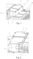
- Figure 3 shows a storage box 1, 2, wherein the pivotable part of the storage box 2 is shown in the pivoted position.
- the pivotable part of the storage box 2 can preferably be pivoted out by up to 90° and has at least one recess 5 so that when pivoting it is not hindered in its pivoting movement by elements located on the vehicle, such as the additional equipment 12.
- Figure 3 An APU, i.e. an additional power supply, is shown as additional equipment 12.
- the recess 5 of the pivotable part of the storage box 2 is thus designed in such a way that the additional equipment 5 does not hinder the pivoting process when pivoting.
- the volume of the recess 5 is accordingly matched to the additional equipment 12 located in the pivoting area.
- the surface of the vehicle is also considered to be additional equipment 5.
- FIG. 3 A maintenance area 14 is shown, which can be closed or opened with a maintenance flap 13. By pivoting the pivotable part of the storage box 2, access to the maintenance flap 13 is now free and this can be opened to allow access to the maintenance area 14.
- the maintenance area 14 in the tower contains electronic and/or hydraulic components that must be made accessible for maintenance. To do this, the maintenance hatch 13 is opened to allow access.
- the maintenance flap 13 is attached to the pivotable part of the storage box 2, so that the pivoting movement is carried out jointly by the pivotable part of the storage box 2 and the maintenance flap 13.
- it is preferably proposed to fasten the maintenance flap 13 to a wall of the pivotable part of the storage box 2 by means of guide rails.
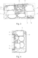
- Figure 4 shows the storage box 1, 2 again, with the pivoted part of the storage box 2 shown pivoted.
- the top view again shows the fastening points 10 to which the parts of the storage box 1, 2 are attached, as well as the pivot bearing 11, by means of which a part of the storage box 2 is designed to be pivotable.
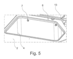
- Figure 5 shows a part of the storage box 2 with the box flap 4 open, whereby a seal 6 can be seen all around the opening.
- This seal 6 provides protection against splash water when the box flap 2 is closed. This protects the objects in the storage box against splash water.
- the stationary part of the storage box 1 is also provided with a seal 6.
- fastening means 7 are attached to the storage box 2, by means of which the movable part of the storage box 2 can be fastened to the tower of the vehicle. This serves to avoid unintentional pivoting movements of the pivotable part of the storage box 2 when the vehicle or the tower is moving.
- the embodiment of the invention shown is shown on a Leopard 2 vehicle.
- the use on Leopard 2 vehicles represents a preferred use of the storage box 1, 2.
- the invention is not limited to the aforementioned features. Rather, other embodiments are conceivable. It is possible to manufacture the storage box from non-metallic materials, for example plastic. It is also conceivable to design two or more parts of the storage box so that they can pivot. To do this, at least one pivot bearing must be arranged at each of the fastening points.
Landscapes
- Engineering & Computer Science (AREA)
- General Engineering & Computer Science (AREA)
- Vehicle Step Arrangements And Article Storage (AREA)
- Ship Loading And Unloading (AREA)
Description
- Die vorliegende Erfindung betrifft ein gepanzertes Fahrzeug gemäß Anspruch 1.
- Staukästen werden verwendet, um bewegliche oder missionsspezifische Ausrüstungsgegenstände und/oder Geräte verstauen zu können. Bei gepanzerten Fahrzeugen ist oftmals nur geringer Stauraum vorhanden. Die genannten Gegenstände und/oder Geräte benötigen jedoch Stauraum und die Anforderung an mehr Stauraum wird größer.
- Dazu offenbart beispielsweise die
DE 10 2012 108 527 B4 ein Heckstaukasten für ein Lastfahrzeug, welcher im Bereich des Fahrzeugchassis angebracht ist. Dieser Staukasten ist beweglich gestaltet, nämlich längsbeweglich, sodass eine Stauraumvergrößerung und/oder ein vereinfachter Zugriff auf den Stauraum möglich ist.DE 10 2004 025743 A1 offenbart ein Schießmodul mit Zusatzgehäuse. - Beim gepanzerten Fahrzeug jedoch ist eine solche Umsetzung schwierig, da das Chassis rundum möglichst geschlossen sein soll.
- Deshalb ist es bei gepanzerten Fahrzeugen bekannt, den Stauraum in Form von Staukästen an einem Fahrzeugaufbau, beispielsweise einen Turm, zu befestigen. Hierzu ist bekannt, einen Staukasten heckseitig am Turm durch Befestigungspunkte zu befestigen.
- Eine Schwierigkeit für am Turm befestigte Schaukästen ist jedoch, dass an den heckseitigen Positionen, an welchen die Staukästen angeordnet werden, sich ebenfalls häufig eine Wartungsklappe befindet. Diese ist notwendig und somit steht der Bereich vor der Wartungsklappe nur begrenzt als Stauraum zur Verfügung. Dementsprechend gering ist das Stauvolumen eines solchen Staukastens.
- Aufgabe der vorliegenden Erfindung ist daher, ein gepanzertes Fahrzeug mit einem Staukasten zu schaffen, mit möglichst großem Stauvolumen, welcher den Zugang zur Wartungsklappe am Turm eines gepanzerten Fahrzeuges nicht behindert.
- Diese Aufgabe wird mit den Merkmalen des unabhängigen Anspruchs 1 gelöst.
- Hierzu wird ein gepanzertes Fahrzeug mit einem Turm, einem Staukasten und mindestens einem Befestigungspunkt am Turm vorgeschlagen, der Staukasten umfassend mindestens eine Kastenklappe, wobei der Staukasten mindestens zweiteilig ausgeführt ist, wobei einer der Teile des Staukastens schwenkbar durch mindestens ein Schwenklager an einem der Befestigungspunkte angeordnet werden kann, wobei jeder Teil des Staukastens eine Öffnung aufweist, welche durch eine Kastenklappe verschlossen werden kann, wobei ein Wartungsbereich in dem Turm vorgesehen ist, welcher durch eine Wartungsklappe zugänglich ist, und wobei die Wartungsklappe an dem schwenkbaren Teil des Staukastens angebracht ist, sodass die Schwenkbewegung von dem schwenkbaren Teil des Staukastens und der Wartungsklappe gemeinsam ausgeführt wird. An dem Turm ist mindestens ein Befestigungspunkt vorgesehen, an welchen der Staukasten befestigt werden kann. Bevorzugterweise sind diese Befestigungspunkte als heckseitige Anordnung vorgesehen.
- Der Staukasten ist so gestaltet, dass er durch mindestens eine Kastenklappe zugänglich ist. Dazu ist die Kastenklappe so gestaltet, dass sie mindestens eine Öffnung im Staukasten verschließen kann. Die Kastenklappe ist weiterhin so gestaltet, dass sie die Öffnung auch freigeben kann und somit freien Zugang zum Inneren des Staukastens gewährleistet.
- Dazu können Scharniere vorgesehen sein, um die Kastenklappe schwenkbar zu gestalten. Es ist jedoch ebenfalls möglich, einfache Befestigungsmöglichkeiten wie Verschraubungen vorzusehen, um dadurch die Kastenklappe auf der Öffnung befestigen bzw. lösen zu können.
- Erfindungsgemäß ist der Staukasten mindestens zweiteilig ausgeführt, wobei einer der beiden Teile des Staukastens schwenkbar gestaltet ist. Durch mindestens ein Schwenklager an einem der Befestigungspunkte ist somit ein Teil des Staukastens schwenkbar an den Befestigungspunkt angeordnet.
- Jeder Teil des Staukastens ist ein für sich geschlossenes Element, sodass nach Befestigung der Kastenklappe auf einem Teil des Staukastens dieser rundherum geschlossen ist. Alle Teile des Staukastens bilden zusammen den Staukasten.
- Durch die Befestigungspunkte am Turm wird der Staukasten mit der Turmbewegung verschwenkt und zumindest der schwenkbare Teil des Staukastens kann weiterhin durch das Schwenklager verschwenkt werden.
- Durch die Verschwenkung einer der Teile des Staukastens kann somit der Staukasten auch teilweise oder ganz vor einer Wartungsklappe des Turms angeordnet werden. Für den Zugang zur Wartungsklappe muss dann einfach der schwenkbare Teil des Staukastens weggeschwenkt werden, um freien Zugriff zur Wartungsklappe zu gewährleisten. Für einen solchen freien Zugang zur Wartungsklappe ist es dazu notwendig, dass lediglich der Teil des Staukastens, der schwenkbar gestaltet ist, vor die Wartungsklappe angeordnet wird.
- Im Schwenkbereich des schwenkbaren Teils des Staukastens können sich fahrzeugseitige Aufbauten und/oder Gerätschaften befinden, welche in den Schwenkraum hineinragen. Damit diese das Verschwenken des schwenkbaren Teils des Staukastens nicht behindern, ist in einer bevorzugten Ausführungsform mindestens eine Ausnehmung am schwenkbaren Teil des Staukasten vorgesehen, welcher so dimensioniert ist, dass entsprechende Zusatzgeräte oder Aufbauten des Fahrzeugs den schwenkbaren Teil des Staukasten in seiner Schwenkbewegung nicht behindern.
- In einer weiteren, bevorzugten Ausführungsform sind Dichtungen zwischen den Öffnungen und den Kastenklappen vorgesehen, um den Staubereich des Staukastens vor Spritzwasser zu schützen. Die Dichtung ist hierzu umlaufend um die Öffnung angeordnet und durch die Befestigung der Kastenklappe am Staukasten wird dann durch die Dichtung der Staukasten gegen Spritzwasser geschützt.
- Ebenfalls bevorzugterweise sind Befestigungsmittel vorgesehen, um den schwenkbaren Teil des Staukastens zu arretieren. Dies soll ungewollte Schwingbewegungen bei einer Bewegung des Turms verhindern bzw. bei einer Bewegung des Fahrzeugs. Dazu kann eine Schraubverbindung als Befestigungsmittel vorgesehen sein, womit der bewegliche Teil des Staukastens am Turm arretiert werden kann. Auch eine magnetische Arretierung ist denkbar, ebenso wie eine Feststellung des Schwenklagers.
- Der am Turm ortsfeste, stationäre Teil des Staukastens ist genauso an mindestens einem der Befestigungspunkte befestigt, wie es bereits von den herkömmlichen aus dem Stand der Technik bekannten Staukästen bekannt ist. Das bedeutet, dass nur ein geringer Aufwand notwendig ist, um entsprechend vorhandene Staukästen durch die neue Ausführung eines Staukastens zu ersetzen.
- Eine dem Turm zugewandten Seite des schwenkbaren Teils des Staukastens ist bereits mit der Wartungsklappe am Turm verbunden, sodass bei Schwenkbewegung nicht nur der schwenkbare Teil des Staukastens verschwenkt wird, sondern auch die Wartungsklappe. Dadurch ist es sehr einfach möglich, den Wartungsbereich zugänglich zu machen, nämlich lediglich durch verschwenken des schwenkbaren Teils des Staukastens. Nach Arretierung des schwenkbaren Teils des Staukastens ist dann auch die Wartungsklappe arretiert und der Wartungsbereich verschlossen.
- Der Staukasten selbst kann durch Unterteilungen in kleinere Bereiche unterteilt werden und ist von seinem Gesamtvolumen ähnlich wie das Volumen der bereits aus dem Stand der Technik bekannten Staukästen, wobei nun allerdings auch der Bereich vor der Stauklappe vollständig genutzt werden kann.
- Bevorzugt besteht der Staukasten aus Stahl. Hierbei können spezielle gehärtete Stähle genutzt werden, wenn besondere Sicherheitsanforderungen an den Staukasten zu stellen sind. Ebenso kann der Staukasten auch aus dem gleichem Material gefertigt werden, wie das Fahrzeug bzw. der Turm, beispielsweise aus Baustahl. Je nach Anforderung können die Werkstoffe auch kombiniert werden.
- Der Schwenkbereich des schwenkbaren Teils des Staukastens ist bevorzugterweise so gestaltet, dass dieser Teil bis zu 90° ausgeschwenkt werden kann.
- Zusätzlich zu den möglichen Unterteilungen des Stauraums sind ebenfalls Aufnahmen oder Befestigungspunkte für die zu verstauenden Geräte bzw. Gegenstände möglich.
- Bevorzugterweise wird die Verwendung des Staukastens in einem Leopard 2-Fahrzeug vorgeschlagen, da hierzu die bereits vorgenannten, nicht verschwenkbaren Staukästen bekannt sind und die bereits benötigten Befestigungspunkte aufweisen. Diese Staukästen können mit der vorliegenden Ausgestaltung maßgeblich verbessert werden.
- Weitere Merkmale ergeben sich aus den beigefügten Zeichnungen. Es zeigen:
- Figur 1:
- Perspektivische Ansicht eines Staukastens;
- Figur 2:
- Eine perspektivische Ansicht auf den schwenkbaren Teil eines Staukastens;
- Figur 3:
- Perspektivische Ansicht auf einen teilweise verschwenkten Staukasten mit Wartungsbereich und Wartungsklappe;
- Figur 4:
- Eine Draufsicht auf einen Staukasten;
- Figur 5:
- Perspektivische Ansicht in eine Öffnung eines Staukastens.
-
Figur 1 zeigt eine perspektivische Ansicht eines Staukastens 1, 2. Angeordnet ist der Staukasten auf einem gepanzerten Fahrzeug, welches einen Turm aufweist. - Der Staukasten ist hierbei zweigeteilt und es existiert ein stationärer Teil des Staukastens 1 welcher ortsfest am Turm angebracht ist. Die Anbringung befindet sich heckseitig am Turm. Ebenfalls existiert ein zweiter Teil des Staukastens 2, welcher schwenkbar am Turm angeordnet ist. Beide Teile des Staukastens 1, 2 sind an Befestigungspunkten 10 angeordnet. Diese Befestigungspunkte 10 befinden sich am Turm des Fahrzeugs, wobei der schwenkbare Teil des Staukasten 2 mittels Schwenklager 11 an einem der Befestigungspunkte 10 angeordnet ist. Die befestigungspunkte 10 sind hierbei als senkrechte Säule ausgeführt.
- Zu sehen sind ebenfalls zwei Kastenklappen 3, 4 jeweils eine Kastenklappe 3, 4 für jeden Teil des Staukastens 1, 2. Die Kastenklappen 3, 4 dienen dazu, den Staukasten 1, 2 öffnen zu können um an den Innenraum des Staukastens zu gelangen. Der Innenraum des Staukastens 1, 2 kann dann Geräte und/oder Zubehör aufnehmen, die während der Fahrt mit dem Fahrzeug mitgeführt werden sollen.
- Die Kastenklappen 3, 4 sind dazu so ausgestaltet, dass sie an den jeweiligen Teil des Staukasten 1, 2 befestigt werden können und ihn somit verschließen oder durch geeignete Mittel geöffnet werden können.
- Am Fahrzeug selbst können Zusatzausrüstungen 12, wie z.B. Energieversorgungen, vorgesehen sein.
-
Figur 2 zeigt ebenfalls eine perspektivische Ansicht auf den Staukasten 1, 2, nur dieses Mal aus der Sicht des schwenkbaren Teils des Staukastens 2. Wie bereits beschrieben, ist der schwenkbare Teil des Staukasten 2 durch mindestens ein Schwenklager 11 an einem Befestigungspunkt 10 angeordnet und kann somit in der Schwenkachse der Schwenklager 11 verschwenkt werden. - Die Befestigungspunkte 10 sind jeweils am Turm angeordnet. In dieser Ausführungsform ist die Anordnung an der Heckseite des Turmes gezeigt. Die Befestigungspunkte 10 können dazu statt punktförmig auch flächig ausgeführt sein, sodass mehrere Schwenklager 11 an einem Befestigungspunkt 10 angeordnet werden können.
-
Figur 3 zeigt einen Staukasten 1, 2, wobei der schwenkbare Teil des Staukastens 2 in verschwenkter Position dargestellt ist. Der schwenkbare Teil des Staukastens 2 kann bevorzugterweise bis zu 90° ausgeschwenkt werden und verfügt über mindestens eine Ausnehmung 5, um beim Verschwenken nicht durch am Fahrzeug befindliche Elemente, wie beispielsweise der Zusatzausrüstung 12, in ihrer Schwenkbewegung behindert zu werden. - Dazu wird in
Figur 3 als Zusatzausrüstung 12 eine APU gezeigt, also eine zusätzliche Energieversorgung. Die Ausnehmung 5 des schwenkbaren Teils des Staukastens 2 ist somit derart gestaltet, dass beim Verschwenken die Zusatzausrüstung 5 den Schwenkvorgang nicht behindert. Entsprechend ist das Volumen der Ausnehmung 5 auf die im Schwenkbereich befindliche Zusatzausrüstung 12 abgestimmt. Als Zusatzausrüstung 5 wird hierbei auch die Oberfläche des Fahrzeugs angesehen. - Ebenfalls in
Figur 3 gezeigt ist ein Wartungsbereich 14, welcher mit einer Wartungsklappe 13 geschlossen oder geöffnet werden kann. Durch das Verschwenken des schwenkbaren Teils des Staukasten 2 ist nun der Zugang zur Wartungsklappe 13 frei und diese kann geöffnet werden, um den Zugang zum Wartungsbereich 14 zu ermöglichen. - Der Wartungsbereich 14 im Turm beinhaltet elektronische und/oder hydraulische Komponenten, die der Wartung zugänglich gemacht werden müssen. Dazu wird die Wartungsklappe 13 geöffnet, sodass der Zugang ermöglicht wird.
- Die Wartungsklappe 13 ist an dem schwenkbaren Teil des Staukasten 2 angebracht, sodass die Schwenkbewegung von dem schwenkbaren Teil des Staukastens 2 und der Wartungsklappe 13 gemeinsam ausgeführt wird. Hierzu wird bevorzugterweise vorgeschlagen, die Wartungsklappe 13 durch Laufschienen an einer Wand des verschwenkbaren Teils des Staukastens 2 zu befestigen.
-
Figur 4 zeigt noch einmal den Staukasten 1, 2, wobei der verschwenkte Teil des Staukastens 2 verschwenkt dargestellt ist. In der Draufsicht zu erkennen sind wiederum die Befestigungspunkte 10, an welchen die Teile des Staukastens 1, 2 befestigt sind sowie das Schwenklager 11, durch welches ein Teil des Staukastens 2 verschwenkbar gestaltet ist. -
Figur 5 zeigt einen Teil des Staukastens 2 mit geöffneter Kastenklappe 4, wobei umlaufend um die Öffnung eine Dichtung 6 zu erkennen ist. Diese Dichtung 6 sorgt bei geschlossener Kastenklappe 2 für einen Schutz gegen Spritzwasser. Hierdurch sind die Gegenstände im Staukasten gegen Spritzwasser geschützt. Ebenso ist auch der ortsfeste Teil des Staukastens 1 mit einer Dichtung 6 versehen. - Es wird vorgeschlagen, eine Arretiermöglichkeit für den beweglichen Teil des Staukastens 2 vorzusehen. Dazu sind Befestigungsmittel 7 am Staukasten 2 angebracht, durch welche der bewegliche Teil des Staukastens 2 an den Turm des Fahrzeugs befestigt werden kann. Dies dient dazu, bei der Bewegung des Fahrzeuges oder der Bewegung des Turms unabsichtliche Schwenkbewegungen des schwenkbaren Teils des Staukasten 2 zu vermeiden.
- In den Figuren ist das gezeigte Ausführungsbeispiel der Erfindung an einem Leopard 2-Fahrzeug gezeigt. Die Verwendungen an Leopard 2-Fahrzeugen stellt eine bevorzugte Verwendung des Staukastens 1, 2 dar.
- Die Erfindung ist nicht auf die vorgenannten Merkmale beschränkt. Vielmehr sind weitere Ausgestaltungen denkbar. So ist es möglich, den Staukasten auch aus nicht metallischen Werkstoffen herzustellen, beispielsweise aus Kunststoff. Ebenso ist denkbar, zwei oder mehr Teile des Staukastens schwenkbar zu gestalten. Dazu muss dann jeweils mindestens ein Schwenklager an einem der Befestigungspunkte angeordnet sein.
-
- 1-
- Staukasten, stationär
- 2-
- Staukasten, schwenkbar
- 3-
- Kastenklappe an 1
- 4-
- Kastenklappe an 2
- 5-
- Ausnehmung
- 6-
- Dichtung
- 7-
- Befestigungsmittel
- 10-
- Befestigungspunkt
- 11-
- Schwenklager
- 12-
- Zusatzausrüstung
- 13-
- Wartungsklappe
- 14-
- Wartungsbereich
Claims (8)
- Gepanzertes Fahrzeug mit einem Turm, einem Staukasten (1, 2) und mindestens einem Befestigungspunkt (10) am Turm, der Staukasten umfassend mindestens eine Kastenklappe, wobei der Staukasten (1, 2) mindestens zweiteilig ausgeführt ist, wobei einer der Teile des Staukastens (2) schwenkbar durch mindestens ein Schwenklager (11) an einem der Befestigungspunkte (10) angeordnet werden kann, wobei jeder Teil des Staukastens (1, 2) eine Öffnung aufweist, welche durch eine Kastenklappe (3, 4) verschlossen werden kann, wobei ein Wartungsbereich (14) in dem Turm vorgesehen ist, welcher durch eine Wartungsklappe (13) zugänglich ist, und wobei die Wartungsklappe (13) an dem schwenkbaren Teil des Staukastens (2) angebracht ist, sodass die Schwenkbewegung von dem schwenkbaren Teil des Staukastens (2) und der Wartungsklappe (13) gemeinsam ausgeführt wird.
- Gepanzertes Fahrzeug nach Anspruch 1, dadurch gekennzeichnet, dass mindestens ein Teil des Staukastens (1) stationär und unbeweglich an einem der Befestigungspunkte (10) angeordnet ist.
- Gepanzertes Fahrzeug nach einem der Ansprüche 1 oder 2, dadurch gekennzeichnet, dass mindestens eine Ausnehmung (5) an dem schwenkbaren Teil des Staukastens (2) vorgesehen ist, um die Bewegungsfreiheit des schwenkbaren Teils des Staukastens (2) zu gewährleisten.
- Gepanzertes Fahrzeug nach Anspruch 3, dadurch gekennzeichnet, dass Zusatzausrüstung (12) am Fahrzeug vorgesehen ist, welche zumindest teilweise in den Schwenkbereich des schwenkbaren Teils des Staukastens (2) hineinragt und die Ausnehmung (5) auf diese Zusatzausrüstung (12) abgestimmt ist.
- Gepanzertes Fahrzeug nach einem der Ansprüche 1 bis 4, dadurch gekennzeichnet, dass Dichtungen (6) zwischen Öffnung und Kastenklappe (3, 4) vorgesehen sind.
- Gepanzertes Fahrzeug nach einem der Ansprüche 1 bis 5, dadurch gekennzeichnet, dass Befestigungsmittel (7) vorgesehen sind, um den schwenkbaren Teil des Staukastens (2) zu arretieren.
- Gepanzertes Fahrzeug nach einem der Ansprüche 1 bis 6, dadurch gekennzeichnet, dass die Wartungsklappe (13) von dem schwenkbaren Teil des Staukastens (2) verdeckt werden kann.
- Gepanzertes Fahrzeug nach einem der Ansprüche 1 bis 7, dadurch gekennzeichnet, dass Unterteilungen im Staukasten (1, 2) vorgesehen sind.
Applications Claiming Priority (2)
| Application Number | Priority Date | Filing Date | Title |
|---|---|---|---|
| DE202017104124.7U DE202017104124U1 (de) | 2017-07-11 | 2017-07-11 | Staukasten für ein gepanzertes Fahrzeug |
| PCT/EP2018/067349 WO2019011656A1 (de) | 2017-07-11 | 2018-06-28 | Staukasten für ein gepanzertes fahrzeug |
Publications (3)
| Publication Number | Publication Date |
|---|---|
| EP3652495A1 EP3652495A1 (de) | 2020-05-20 |
| EP3652495B1 EP3652495B1 (de) | 2022-04-06 |
| EP3652495B2 true EP3652495B2 (de) | 2025-02-26 |
Family
ID=60254842
Family Applications (1)
| Application Number | Title | Priority Date | Filing Date |
|---|---|---|---|
| EP18737198.4A Active EP3652495B2 (de) | 2017-07-11 | 2018-06-28 | Staukasten für ein gepanzertes fahrzeug |
Country Status (4)
| Country | Link |
|---|---|
| EP (1) | EP3652495B2 (de) |
| DE (1) | DE202017104124U1 (de) |
| ES (1) | ES2911206T5 (de) |
| WO (1) | WO2019011656A1 (de) |
Families Citing this family (1)
| Publication number | Priority date | Publication date | Assignee | Title |
|---|---|---|---|---|
| DE202023104690U1 (de) * | 2023-08-18 | 2023-11-16 | Krauss-Maffei Wegmann Gmbh & Co. Kg | Fahrzeug, insbesondere militärisches Kampffahrzeug |
Family Cites Families (27)
| Publication number | Priority date | Publication date | Assignee | Title |
|---|---|---|---|---|
| DE2235728A1 (de) | 1972-07-21 | 1974-01-31 | Porsche Ag | Panzerfahrzeug |
| DE2436581C2 (de) * | 1974-07-30 | 1984-12-06 | Krauss-Maffei AG, 8000 München | Panzerkampffahrzeug mit einem Panzerturm |
| DE2503093A1 (de) | 1975-01-25 | 1976-07-29 | Krauss Maffei Ag | Fahrzeug |
| US4564167A (en) | 1983-10-31 | 1986-01-14 | Smith James H | Tool box mounting assembly |
| US4928574A (en) * | 1987-10-05 | 1990-05-29 | Western Design Corporation | Ammunition magazine system |
| DE3931895A1 (de) | 1989-09-25 | 1994-12-15 | Wegmann & Co Gmbh | Einrichtung zur Anordnung von adaptierbaren Panzerungselementen an gegen Waffeneinwirkung zu schützenden Objekten, insbesondere an Kampffahrzeugen |
| US4971234A (en) | 1990-01-12 | 1990-11-20 | Hay Peter B | Pivotable storage unit for vehicles |
| DE4200903A1 (de) * | 1992-01-16 | 1993-07-22 | Wegmann & Co Gmbh | Munitionsbunker an einem kampfpanzerturm |
| US5398987A (en) | 1993-08-02 | 1995-03-21 | Sturgis; John C. | Tool box assembly |
| FR2708536B1 (fr) | 1993-08-04 | 1995-09-22 | Giat Ind Sa | Engin motorisé de dépannage. |
| SE501401C2 (sv) | 1993-12-17 | 1995-02-06 | Bofors Ab | Ammunitionshanteringssystem för artilleripjäser |
| FR2747760B1 (fr) | 1996-04-23 | 1998-06-12 | Giat Ind Sa | Dispositif de fixation d'un caisson sur une structure |
| DE10144368B4 (de) | 2001-09-10 | 2004-02-12 | Rheinmetall Landsysteme Gmbh | Vorrichtung für ein gepanzertes Transportfahrzeug als Batterie-Schwenkmechanismus |
| DE102004025743A1 (de) * | 2004-05-26 | 2005-12-15 | Krauss-Maffei Wegmann Gmbh & Co. Kg | Schießmodul |
| FR2884599B1 (fr) | 2005-04-19 | 2007-05-18 | Giat Ind Sa | Dispositif d'alimentation d'une arme a partir de plusieurs caisses a munitions |
| FR2893337B1 (fr) | 2005-11-14 | 2008-02-01 | Giat Ind Sa | Vehicule de genie civil ou militaire |
| FR2893568B1 (fr) | 2005-11-21 | 2009-07-10 | Giat Ind Sa | Coffre logistique |
| FR2893569B1 (fr) | 2005-11-21 | 2010-04-09 | Giat Ind Sa | Dispositif de fixation d'un coffre logistique et coffre logistique mettant en oeuvre un tel dispositif |
| US7309093B2 (en) | 2006-04-18 | 2007-12-18 | Clinton Ward | Swing-out tool chest |
| KR100945190B1 (ko) | 2007-10-02 | 2010-03-03 | 볼보 컨스트럭션 이키프먼트 홀딩 스웨덴 에이비 | 장비의 앞쪽 방향으로 개방되는 툴박스를 갖는 중장비 |
| US20090200351A1 (en) | 2008-02-07 | 2009-08-13 | Steven Dale Brallier | Truck tool box and hinge system |
| DE102012108527B4 (de) | 2012-09-12 | 2015-12-31 | INFATEC Consulting für innovative Fahrzeugtechnik GmbH | Lastfahrzeug mit einem Schutzrahmen |
| AU2014210633B2 (en) | 2013-08-08 | 2017-07-20 | Craig, Geoffrey Thomas MR | Cargo carrier |
| US20150086312A1 (en) | 2013-09-20 | 2015-03-26 | David Ohnesorge | Storage Assembly |
| KR101506649B1 (ko) | 2014-01-20 | 2015-03-27 | 김정수 | 차량 적재함의 수납함 |
| KR102299047B1 (ko) | 2014-10-30 | 2021-09-06 | 주식회사 두산 | 이동식 공구박스를 구비한 지게차 |
| JP6495082B2 (ja) | 2015-04-17 | 2019-04-03 | 日立建機株式会社 | 建設機械 |
-
2017
- 2017-07-11 DE DE202017104124.7U patent/DE202017104124U1/de active Active
-
2018
- 2018-06-28 WO PCT/EP2018/067349 patent/WO2019011656A1/de not_active Ceased
- 2018-06-28 EP EP18737198.4A patent/EP3652495B2/de active Active
- 2018-06-28 ES ES18737198T patent/ES2911206T5/es active Active
Non-Patent Citations (1)
| Title |
|---|
| ANTONSON THOMAS: "The Danish Leopard 2A5", 1 January 2008, BARBAROSSA BOOKS, ISBN: 978-1-84768-027-3, pages: 3 - 5, 23 - 32, 93, 95, 159, 166, 167 † |
Also Published As
| Publication number | Publication date |
|---|---|
| EP3652495A1 (de) | 2020-05-20 |
| ES2911206T3 (es) | 2022-05-18 |
| WO2019011656A1 (de) | 2019-01-17 |
| EP3652495B1 (de) | 2022-04-06 |
| ES2911206T5 (en) | 2025-06-18 |
| DE202017104124U1 (de) | 2017-10-13 |
Similar Documents
| Publication | Publication Date | Title |
|---|---|---|
| DE102018128972B4 (de) | Klappe mit Öffnungsmechanismus | |
| EP2166154B1 (de) | Schutzdachaufbau für den Führerstand einer Baumaschine | |
| DE202018106610U1 (de) | Fahrzeugtürbaugruppen | |
| EP3128108A1 (de) | Griffeinheit | |
| EP3652495B2 (de) | Staukasten für ein gepanzertes fahrzeug | |
| DE102007036926A1 (de) | Hutablage für ein Kraftfahrzeug | |
| DE102007037987B3 (de) | Verstellbares Karosserieelement für ein Fahrzeug | |
| DE202004001804U1 (de) | Konsole, insbesondere Mittelkonsole für ein Kraftfahrzeug | |
| EP1398217B1 (de) | Deckel für ein Ablagefach in einem Fahrzeug | |
| EP2256027B1 (de) | Unterseeboot | |
| DE102013012126A1 (de) | Kraftfahrzeug mit einem verschiebbaren Staufach | |
| DE102013100331A1 (de) | Schutzvorrichtung für eine Optik | |
| EP0863378B1 (de) | Luke für ein gepanzertes Kampffahrzeug | |
| DE2647104B2 (de) | Lagerung für eine schwenkbare Abdeckplatte über dem Kofferraum von Kraftfahrzeugen | |
| DE102005042288A1 (de) | Abdeckung für die Ladekante eines Kraftfahrzeuges und Kraftfahrzeug mit einer solchen Abdeckung | |
| DE3508660C2 (de) | Kampffahrzeug mit scheitellafettierter Waffenanlage | |
| DE10133147B4 (de) | Gepanzertes Transportfahrzeug | |
| DE102011109038A1 (de) | Windleiteinrichtung für einen Aufbau eines Fahrzeugs | |
| DE102011110160B4 (de) | Gepäckablagefach für ein Flugzeug, Gepäckablagereihe sowie Flugzeug mit dem Gepäckablagefach bzw. der Gepäckablagereihe | |
| DE102011110406B4 (de) | Gepäckablagefach für ein Flugzeug, Gepäckablagereihe sowie Flugzeug mit dem Gepäckablagefach bzw. der Gepäckablagereihe | |
| DE202013100174U1 (de) | Schutzvorrichtung für eine Optik | |
| EP3835103B1 (de) | Vorrichtung zum verkleiden eines nutzfahrzeugs | |
| DE102023123867A1 (de) | Öffenbare Klappe für ein Kraftfahrzeug sowie Kraftfahrzeug mit öffenbarer Haube | |
| DE102022113474A1 (de) | Kraftfahrzeug | |
| DE102009024375A1 (de) | Vorrichtung zur Anbringung einer Kofferraumabdeckung an einer Heckklappe |
Legal Events
| Date | Code | Title | Description |
|---|---|---|---|
| STAA | Information on the status of an ep patent application or granted ep patent |
Free format text: STATUS: UNKNOWN |
|
| STAA | Information on the status of an ep patent application or granted ep patent |
Free format text: STATUS: THE INTERNATIONAL PUBLICATION HAS BEEN MADE |
|
| PUAI | Public reference made under article 153(3) epc to a published international application that has entered the european phase |
Free format text: ORIGINAL CODE: 0009012 |
|
| STAA | Information on the status of an ep patent application or granted ep patent |
Free format text: STATUS: REQUEST FOR EXAMINATION WAS MADE |
|
| 17P | Request for examination filed |
Effective date: 20191206 |
|
| AK | Designated contracting states |
Kind code of ref document: A1 Designated state(s): AL AT BE BG CH CY CZ DE DK EE ES FI FR GB GR HR HU IE IS IT LI LT LU LV MC MK MT NL NO PL PT RO RS SE SI SK SM TR |
|
| AX | Request for extension of the european patent |
Extension state: BA ME |
|
| DAV | Request for validation of the european patent (deleted) | ||
| DAX | Request for extension of the european patent (deleted) | ||
| GRAP | Despatch of communication of intention to grant a patent |
Free format text: ORIGINAL CODE: EPIDOSNIGR1 |
|
| STAA | Information on the status of an ep patent application or granted ep patent |
Free format text: STATUS: GRANT OF PATENT IS INTENDED |
|
| INTG | Intention to grant announced |
Effective date: 20211130 |
|
| GRAS | Grant fee paid |
Free format text: ORIGINAL CODE: EPIDOSNIGR3 |
|
| GRAA | (expected) grant |
Free format text: ORIGINAL CODE: 0009210 |
|
| STAA | Information on the status of an ep patent application or granted ep patent |
Free format text: STATUS: THE PATENT HAS BEEN GRANTED |
|
| AK | Designated contracting states |
Kind code of ref document: B1 Designated state(s): AL AT BE BG CH CY CZ DE DK EE ES FI FR GB GR HR HU IE IS IT LI LT LU LV MC MK MT NL NO PL PT RO RS SE SI SK SM TR |
|
| REG | Reference to a national code |
Ref country code: GB Ref legal event code: FG4D Free format text: NOT ENGLISH |
|
| REG | Reference to a national code |
Ref country code: CH Ref legal event code: EP |
|
| REG | Reference to a national code |
Ref country code: AT Ref legal event code: REF Ref document number: 1481721 Country of ref document: AT Kind code of ref document: T Effective date: 20220415 |
|
| REG | Reference to a national code |
Ref country code: DE Ref legal event code: R096 Ref document number: 502018009343 Country of ref document: DE |
|
| REG | Reference to a national code |
Ref country code: IE Ref legal event code: FG4D Free format text: LANGUAGE OF EP DOCUMENT: GERMAN |
|
| REG | Reference to a national code |
Ref country code: ES Ref legal event code: FG2A Ref document number: 2911206 Country of ref document: ES Kind code of ref document: T3 Effective date: 20220518 |
|
| REG | Reference to a national code |
Ref country code: NL Ref legal event code: FP |
|
| REG | Reference to a national code |
Ref country code: LT Ref legal event code: MG9D |
|
| PG25 | Lapsed in a contracting state [announced via postgrant information from national office to epo] |
Ref country code: SE Free format text: LAPSE BECAUSE OF FAILURE TO SUBMIT A TRANSLATION OF THE DESCRIPTION OR TO PAY THE FEE WITHIN THE PRESCRIBED TIME-LIMIT Effective date: 20220406 Ref country code: PT Free format text: LAPSE BECAUSE OF FAILURE TO SUBMIT A TRANSLATION OF THE DESCRIPTION OR TO PAY THE FEE WITHIN THE PRESCRIBED TIME-LIMIT Effective date: 20220808 Ref country code: NO Free format text: LAPSE BECAUSE OF FAILURE TO SUBMIT A TRANSLATION OF THE DESCRIPTION OR TO PAY THE FEE WITHIN THE PRESCRIBED TIME-LIMIT Effective date: 20220706 Ref country code: LT Free format text: LAPSE BECAUSE OF FAILURE TO SUBMIT A TRANSLATION OF THE DESCRIPTION OR TO PAY THE FEE WITHIN THE PRESCRIBED TIME-LIMIT Effective date: 20220406 Ref country code: HR Free format text: LAPSE BECAUSE OF FAILURE TO SUBMIT A TRANSLATION OF THE DESCRIPTION OR TO PAY THE FEE WITHIN THE PRESCRIBED TIME-LIMIT Effective date: 20220406 Ref country code: GR Free format text: LAPSE BECAUSE OF FAILURE TO SUBMIT A TRANSLATION OF THE DESCRIPTION OR TO PAY THE FEE WITHIN THE PRESCRIBED TIME-LIMIT Effective date: 20220707 Ref country code: FI Free format text: LAPSE BECAUSE OF FAILURE TO SUBMIT A TRANSLATION OF THE DESCRIPTION OR TO PAY THE FEE WITHIN THE PRESCRIBED TIME-LIMIT Effective date: 20220406 Ref country code: BG Free format text: LAPSE BECAUSE OF FAILURE TO SUBMIT A TRANSLATION OF THE DESCRIPTION OR TO PAY THE FEE WITHIN THE PRESCRIBED TIME-LIMIT Effective date: 20220706 |
|
| PG25 | Lapsed in a contracting state [announced via postgrant information from national office to epo] |
Ref country code: RS Free format text: LAPSE BECAUSE OF FAILURE TO SUBMIT A TRANSLATION OF THE DESCRIPTION OR TO PAY THE FEE WITHIN THE PRESCRIBED TIME-LIMIT Effective date: 20220406 Ref country code: PL Free format text: LAPSE BECAUSE OF FAILURE TO SUBMIT A TRANSLATION OF THE DESCRIPTION OR TO PAY THE FEE WITHIN THE PRESCRIBED TIME-LIMIT Effective date: 20220406 Ref country code: LV Free format text: LAPSE BECAUSE OF FAILURE TO SUBMIT A TRANSLATION OF THE DESCRIPTION OR TO PAY THE FEE WITHIN THE PRESCRIBED TIME-LIMIT Effective date: 20220406 Ref country code: IS Free format text: LAPSE BECAUSE OF FAILURE TO SUBMIT A TRANSLATION OF THE DESCRIPTION OR TO PAY THE FEE WITHIN THE PRESCRIBED TIME-LIMIT Effective date: 20220806 |
|
| REG | Reference to a national code |
Ref country code: DE Ref legal event code: R026 Ref document number: 502018009343 Country of ref document: DE |
|
| PLBI | Opposition filed |
Free format text: ORIGINAL CODE: 0009260 |
|
| PLAX | Notice of opposition and request to file observation + time limit sent |
Free format text: ORIGINAL CODE: EPIDOSNOBS2 |
|
| REG | Reference to a national code |
Ref country code: DE Ref legal event code: R082 Country of ref document: DE Ref country code: DE Ref legal event code: R082 Ref document number: 502018009343 Country of ref document: DE Representative=s name: HKW INTELLECTUAL PROPERTY PARTG MBB, DE |
|
| PLAF | Information modified related to communication of a notice of opposition and request to file observations + time limit |
Free format text: ORIGINAL CODE: EPIDOSCOBS2 |
|
| PG25 | Lapsed in a contracting state [announced via postgrant information from national office to epo] |
Ref country code: SM Free format text: LAPSE BECAUSE OF FAILURE TO SUBMIT A TRANSLATION OF THE DESCRIPTION OR TO PAY THE FEE WITHIN THE PRESCRIBED TIME-LIMIT Effective date: 20220406 Ref country code: SK Free format text: LAPSE BECAUSE OF FAILURE TO SUBMIT A TRANSLATION OF THE DESCRIPTION OR TO PAY THE FEE WITHIN THE PRESCRIBED TIME-LIMIT Effective date: 20220406 Ref country code: RO Free format text: LAPSE BECAUSE OF FAILURE TO SUBMIT A TRANSLATION OF THE DESCRIPTION OR TO PAY THE FEE WITHIN THE PRESCRIBED TIME-LIMIT Effective date: 20220406 Ref country code: MC Free format text: LAPSE BECAUSE OF FAILURE TO SUBMIT A TRANSLATION OF THE DESCRIPTION OR TO PAY THE FEE WITHIN THE PRESCRIBED TIME-LIMIT Effective date: 20220406 Ref country code: EE Free format text: LAPSE BECAUSE OF FAILURE TO SUBMIT A TRANSLATION OF THE DESCRIPTION OR TO PAY THE FEE WITHIN THE PRESCRIBED TIME-LIMIT Effective date: 20220406 Ref country code: DK Free format text: LAPSE BECAUSE OF FAILURE TO SUBMIT A TRANSLATION OF THE DESCRIPTION OR TO PAY THE FEE WITHIN THE PRESCRIBED TIME-LIMIT Effective date: 20220406 Ref country code: CZ Free format text: LAPSE BECAUSE OF FAILURE TO SUBMIT A TRANSLATION OF THE DESCRIPTION OR TO PAY THE FEE WITHIN THE PRESCRIBED TIME-LIMIT Effective date: 20220406 |
|
| 26 | Opposition filed |
Opponent name: KRAUSS-MAFFEI WEGMANN GMBH & CO. KG Effective date: 20230105 |
|
| REG | Reference to a national code |
Ref country code: BE Ref legal event code: MM Effective date: 20220630 |
|
| PG25 | Lapsed in a contracting state [announced via postgrant information from national office to epo] |
Ref country code: AL Free format text: LAPSE BECAUSE OF FAILURE TO SUBMIT A TRANSLATION OF THE DESCRIPTION OR TO PAY THE FEE WITHIN THE PRESCRIBED TIME-LIMIT Effective date: 20220406 |
|
| PG25 | Lapsed in a contracting state [announced via postgrant information from national office to epo] |
Ref country code: LU Free format text: LAPSE BECAUSE OF NON-PAYMENT OF DUE FEES Effective date: 20220628 Ref country code: IE Free format text: LAPSE BECAUSE OF NON-PAYMENT OF DUE FEES Effective date: 20220628 |
|
| PLBB | Reply of patent proprietor to notice(s) of opposition received |
Free format text: ORIGINAL CODE: EPIDOSNOBS3 |
|
| PG25 | Lapsed in a contracting state [announced via postgrant information from national office to epo] |
Ref country code: SI Free format text: LAPSE BECAUSE OF FAILURE TO SUBMIT A TRANSLATION OF THE DESCRIPTION OR TO PAY THE FEE WITHIN THE PRESCRIBED TIME-LIMIT Effective date: 20220406 Ref country code: BE Free format text: LAPSE BECAUSE OF NON-PAYMENT OF DUE FEES Effective date: 20220630 |
|
| PG25 | Lapsed in a contracting state [announced via postgrant information from national office to epo] |
Ref country code: IT Free format text: LAPSE BECAUSE OF FAILURE TO SUBMIT A TRANSLATION OF THE DESCRIPTION OR TO PAY THE FEE WITHIN THE PRESCRIBED TIME-LIMIT Effective date: 20220406 |
|
| PLAB | Opposition data, opponent's data or that of the opponent's representative modified |
Free format text: ORIGINAL CODE: 0009299OPPO |
|
| PG25 | Lapsed in a contracting state [announced via postgrant information from national office to epo] |
Ref country code: MK Free format text: LAPSE BECAUSE OF FAILURE TO SUBMIT A TRANSLATION OF THE DESCRIPTION OR TO PAY THE FEE WITHIN THE PRESCRIBED TIME-LIMIT Effective date: 20220406 Ref country code: CY Free format text: LAPSE BECAUSE OF FAILURE TO SUBMIT A TRANSLATION OF THE DESCRIPTION OR TO PAY THE FEE WITHIN THE PRESCRIBED TIME-LIMIT Effective date: 20220406 |
|
| R26 | Opposition filed (corrected) |
Opponent name: KNDS DEUTSCHLAND GMBH & CO. KG Effective date: 20230105 |
|
| PG25 | Lapsed in a contracting state [announced via postgrant information from national office to epo] |
Ref country code: HU Free format text: LAPSE BECAUSE OF FAILURE TO SUBMIT A TRANSLATION OF THE DESCRIPTION OR TO PAY THE FEE WITHIN THE PRESCRIBED TIME-LIMIT; INVALID AB INITIO Effective date: 20180628 |
|
| PG25 | Lapsed in a contracting state [announced via postgrant information from national office to epo] |
Ref country code: TR Free format text: LAPSE BECAUSE OF FAILURE TO SUBMIT A TRANSLATION OF THE DESCRIPTION OR TO PAY THE FEE WITHIN THE PRESCRIBED TIME-LIMIT Effective date: 20220406 |
|
| PG25 | Lapsed in a contracting state [announced via postgrant information from national office to epo] |
Ref country code: MT Free format text: LAPSE BECAUSE OF FAILURE TO SUBMIT A TRANSLATION OF THE DESCRIPTION OR TO PAY THE FEE WITHIN THE PRESCRIBED TIME-LIMIT Effective date: 20220406 |
|
| PG25 | Lapsed in a contracting state [announced via postgrant information from national office to epo] |
Ref country code: BG Free format text: LAPSE BECAUSE OF FAILURE TO SUBMIT A TRANSLATION OF THE DESCRIPTION OR TO PAY THE FEE WITHIN THE PRESCRIBED TIME-LIMIT Effective date: 20220406 |
|
| PG25 | Lapsed in a contracting state [announced via postgrant information from national office to epo] |
Ref country code: BG Free format text: LAPSE BECAUSE OF FAILURE TO SUBMIT A TRANSLATION OF THE DESCRIPTION OR TO PAY THE FEE WITHIN THE PRESCRIBED TIME-LIMIT Effective date: 20220406 |
|
| PUAH | Patent maintained in amended form |
Free format text: ORIGINAL CODE: 0009272 |
|
| STAA | Information on the status of an ep patent application or granted ep patent |
Free format text: STATUS: PATENT MAINTAINED AS AMENDED |
|
| 27A | Patent maintained in amended form |
Effective date: 20250226 |
|
| AK | Designated contracting states |
Kind code of ref document: B2 Designated state(s): AL AT BE BG CH CY CZ DE DK EE ES FI FR GB GR HR HU IE IS IT LI LT LU LV MC MK MT NL NO PL PT RO RS SE SI SK SM TR |
|
| REG | Reference to a national code |
Ref country code: DE Ref legal event code: R102 Ref document number: 502018009343 Country of ref document: DE |
|
| REG | Reference to a national code |
Ref country code: DE Ref legal event code: R082 Ref document number: 502018009343 Country of ref document: DE Representative=s name: HKW INTELLECTUAL PROPERTY PARTG MBB, DE |
|
| REG | Reference to a national code |
Ref country code: NL Ref legal event code: FP |
|
| REG | Reference to a national code |
Ref country code: ES Ref legal event code: DC2A Ref document number: 2911206 Country of ref document: ES Kind code of ref document: T5 Effective date: 20250618 |
|
| PGFP | Annual fee paid to national office [announced via postgrant information from national office to epo] |
Ref country code: DE Payment date: 20250618 Year of fee payment: 8 |
|
| PGFP | Annual fee paid to national office [announced via postgrant information from national office to epo] |
Ref country code: GB Payment date: 20250618 Year of fee payment: 8 |
|
| PGFP | Annual fee paid to national office [announced via postgrant information from national office to epo] |
Ref country code: NL Payment date: 20250618 Year of fee payment: 8 |
|
| PGFP | Annual fee paid to national office [announced via postgrant information from national office to epo] |
Ref country code: FR Payment date: 20250626 Year of fee payment: 8 |
|
| PGFP | Annual fee paid to national office [announced via postgrant information from national office to epo] |
Ref country code: AT Payment date: 20250620 Year of fee payment: 8 |
|
| PGFP | Annual fee paid to national office [announced via postgrant information from national office to epo] |
Ref country code: ES Payment date: 20250731 Year of fee payment: 8 |
|
| PGFP | Annual fee paid to national office [announced via postgrant information from national office to epo] |
Ref country code: CH Payment date: 20250701 Year of fee payment: 8 |