EP3639896A1 - Fire/disaster evacuation facility for building - Google Patents
Fire/disaster evacuation facility for building Download PDFInfo
- Publication number
- EP3639896A1 EP3639896A1 EP18818328.9A EP18818328A EP3639896A1 EP 3639896 A1 EP3639896 A1 EP 3639896A1 EP 18818328 A EP18818328 A EP 18818328A EP 3639896 A1 EP3639896 A1 EP 3639896A1
- Authority
- EP
- European Patent Office
- Prior art keywords
- folding
- opening
- wall
- emergency exit
- outer frame
- Prior art date
- Legal status (The legal status is an assumption and is not a legal conclusion. Google has not performed a legal analysis and makes no representation as to the accuracy of the status listed.)
- Granted
Links
- 230000001174 ascending effect Effects 0.000 claims description 23
- 239000006096 absorbing agent Substances 0.000 claims description 7
- 230000035939 shock Effects 0.000 claims description 7
- 230000000149 penetrating effect Effects 0.000 claims description 4
- 238000000034 method Methods 0.000 claims description 3
- 239000011521 glass Substances 0.000 description 8
- 241000282414 Homo sapiens Species 0.000 description 5
- 230000002787 reinforcement Effects 0.000 description 3
- 208000019901 Anxiety disease Diseases 0.000 description 1
- 241000282412 Homo Species 0.000 description 1
- 230000036506 anxiety Effects 0.000 description 1
- 230000004888 barrier function Effects 0.000 description 1
- 230000000903 blocking effect Effects 0.000 description 1
- 230000009194 climbing Effects 0.000 description 1
- 230000000694 effects Effects 0.000 description 1
- 238000007493 shaping process Methods 0.000 description 1
Images


Classifications
-
- A—HUMAN NECESSITIES
- A62—LIFE-SAVING; FIRE-FIGHTING
- A62B—DEVICES, APPARATUS OR METHODS FOR LIFE-SAVING
- A62B5/00—Other devices for rescuing from fire
-
- A—HUMAN NECESSITIES
- A62—LIFE-SAVING; FIRE-FIGHTING
- A62B—DEVICES, APPARATUS OR METHODS FOR LIFE-SAVING
- A62B1/00—Devices for lowering persons from buildings or the like
- A62B1/02—Devices for lowering persons from buildings or the like by making use of rescue cages, bags, or the like
-
- E—FIXED CONSTRUCTIONS
- E04—BUILDING
- E04F—FINISHING WORK ON BUILDINGS, e.g. STAIRS, FLOORS
- E04F11/00—Stairways, ramps, or like structures; Balustrades; Handrails
- E04F11/18—Balustrades; Handrails
-
- E—FIXED CONSTRUCTIONS
- E04—BUILDING
- E04F—FINISHING WORK ON BUILDINGS, e.g. STAIRS, FLOORS
- E04F11/00—Stairways, ramps, or like structures; Balustrades; Handrails
- E04F11/18—Balustrades; Handrails
- E04F11/1865—Collapsible or portable balustrades
-
- E—FIXED CONSTRUCTIONS
- E04—BUILDING
- E04F—FINISHING WORK ON BUILDINGS, e.g. STAIRS, FLOORS
- E04F11/00—Stairways, ramps, or like structures; Balustrades; Handrails
- E04F11/18—Balustrades; Handrails
- E04F2011/1868—Miscellaneous features of handrails not otherwise provided for
- E04F2011/1876—Movable elements, e.g. against sunlight
Definitions
- the present invention relates to a fire/disaster evacuation facility for building, more specifically to the fire/disaster evacuation facility for building that is used as a balcony parapet to prevent falling in ordinary day without fire risk, and whose structure is converted into a fire and a disaster evacuation facility for residents isolated by the fire to be safely evacuated to the ground when the fire occurs.
- the high-rise buildings are increasing in the present day in order to make effective use of a small site and to expand a living space of the building.
- a main entrance door for human access is usually prepared in the high-rise buildings, a veranda is installed in the opposite side of the main entrance door, and a safety parapet for preventing falling is installed on the veranda.
- Such high-rise buildings have an advantage of being able to accommodate a large number of people in the small site, and it is possible to look down the scenery in the high building, and have an advantage of having various convenience facilities inside.
- the high-rise buildings have a disadvantage of having a high frequency of fires due to the residence of many people inside the buildings risend on the small site, and have a problem that once a fire occurred, it could lead to a mass mortality event.
- the descending life line has a problem that is difficult for the general public to operate it, and the other problem of the descending life line is that people cannot overcome their anxiety of using the descending life line in addition to their fear of fire because of the burden of putting the weight of the user on one rope.
- the safety balustrade for fire-escaping may consist of: a first frame blocking the upper glass wall in ordinary day without fire risk, and being pivoted by a hinge fixed to the outer wall of the building and facing the lower glass wall or the lower outer wall in the event of fire; a second frame being placed between the first frame and the upper glass wall to block the upper glass wall in ordinary day without fire risk, and being pivoted to direction of the lower glass wall or the lower outer wall along the first frame in the event of fire; a stepping board, wherein its two ends of one side and two ends of the other side are connected to the first frame and the second frame respectively and it is erected abreast with the upper glass wall to prevent falling accident of upper floor residents in ordinary day without fire risk, and when the first frame and the second frame are pivoted to the direction of the lower glass wall and the lower outer wall, the stepping board is unfolded in the orthogon
- An objective of the present invention is to solve such problems and is to provide the fire/disaster evacuation facility for building which allows people who are isolated in the high-rise building to descend safely to the ground through the veranda when the fire occurs in a high-rise building.
- a fire/disaster evacuation facility for building of the present invention comprises a wall-fixed frame which is fixedly installed on an outer wall of a building facing against a balcony or veranda of the building as a square frame shape; an outer frame which is installed in front of the wall-fixed frame as a front closed square frame shape; a side folding ascending/descending means which comprises a pair of a first side wall and a second side wall which are installed in right and left sides of the wall-fixed frame and the outer frame, and are folded or unfolded with hinge-combination, wherein front upper and lower sides of the first side wall are axially fixed to the outer frame, and rear upper and lower sides of the second side wall are axially fixed to the wall-fixed frame; a lower folding foothold which comprises a first lower board and a second lower board which are installed under the wall-fixed frame and the outer frame, and are folded or unfolded with hinge-combined, wherein front upper and lower sides of the first lower board is axially fixed to
- the fire/disaster evacuation facility for building comprised of such structure is used as a safety parapet for preventing falling in ordinary day without fire risk, and its structure is converted to be used as an evacuation facility for fire evacuation to reduce damage for humans when the fire occurs.
- a fire/disaster evacuation facility for building comprises a wall-fixed frame (1) which is fixedly installed on an outer wall of a building facing against a balcony or veranda of the building as a square frame shape; an outer frame (3) which is installed in front of the wall-fixed frame (1) as a front closed square frame shape; a side folding ascending/descending means (9) which comprises a pair of a first side wall (5) and a second side wall (7) which are installed in right and left sides of the wall-fixed frame (1) and the outer frame (3), and are folded or unfolded with hinge-combination, wherein front upper and lower sides of the first side wall (5) are axially fixed to the outer frame (3), and rear upper and lower sides of the second side wall (7) are axially fixed to the wall-fixed frame (1); a lower folding foothold (15) which comprises a first lower board (11) and a second lower board (13) which are installed under the wall-fixed frame (1) and the outer frame (3), and are folded or unfolde
- the first side wall (5) and the second side wall (7) installed to opens the folding emergency exit opening and closing means (19) are processed in a frame shaping a ladder form thus a man who evacuates from the fire or disaster can move to the lower floor by riding on the first side wall (5) and the second side wall (7).
- the folding emergency exit opening and closing means (19) comprises a first opening and closing door (31) which blocks the emergency exit (17) penetrating the first lower board (11) and is hinge-combined to a front edge of the emergency exit (17), a second opening and closing door (33) which blocks the emergency exit (17) penetrating the second lower board (13), and an opening and closing door hinge (35) which connects the first opening and closing door (31) and the second opening and closing door (33).
- the opening and closing door hinge (35) is placed on a continuous line with a hinge equipped to the lower folding foothold (15) and the first opening and closing door (31) and the second opening and closing door (33) are folded or unfolded according to the lower folding foothold (15).
- a stopping board (37) is additionally attached on an edge of the second opening and closing door (33) coming into contact with the emergency exit (17), so that the stopping board is projected in a backward of the second opening and closing door (33) from the second opening and closing door (33) and hangs on an edge of the emergency exit (17) and prevent the second opening and closing door (33) from being axially rotated in a downward direction of the emergency exit (17) when the second opening and closing door (33) blocks the emergency exit (17).
- a lower shock absorber (39) is equipped, whose one end is axially fixed to the first opening and closing door (31) and the other end is axially fixed to the first lower board (11) and pushes up an open folding emergency exit opening and closing means (19) with a power between the first lower board (11) and the first opening and closing door (31).
- a " ⁇ " shaped knob (41) is equipped on an upper side of the second opening and closing door (33).
- both lower sides of the wall fixed frame (1) spaced by a predetermined height from the side folding ascending/descending means (9) is mounted with a reinforcement chain (29) connecting the wall fixed frame (1) and the outer frame (3).
- the upper evacuation structure converting means (23) comprises a locking bar fixing bracket (43) that is fixedly equipped to an upper side of the outer frame (3) and is projected in a direction of the wall-fixed frame (1), a locking bar (45) whose upper side is fixed and installed to a lower rear side of the locking bar fixing bracket (43) as a straight bar standing in a vertical direction, an outer frame locking means (49) that comprises a hanging hook (47) which when facing the locking bar (45), the locking bar (45) is fixed over and which is interlocked with the upper handle (21) and is elastically shaft-rotated according to operation of the upper handler (21) and releases the held locking bar (45), and that is equipped to the upper side of the wall-fixed frame (1) facing the locking bar (45), and a pair of upper shock absorber (51) whose one end is axially fixed to the upper side of the wall-fixed frame (1) and whose the other end is fixed to the second side wall (7) of the side folding ascending/descending means (9) installed to left or
- the upper evacuation structure converting means (23) comprises a handle bundle (53) which is equipped with the upper handle (21) shaft-rotating clockwise or counterclockwise on a front, a handle bracket (55) which is equipped to a rear side of the handle bundle (53), a rotating volt (57) which passes through the handle bracket (55), extends to a rear of the handle bundle (53) and rotates according to the upper handle (21), a first nut (59) which fastens to the rotating volt (57), a lever (61) of which one side is penetrated and fixed to the rotating volt (57), and rotates according to the rotating volt (57) as a bar shape, a second nut (63) which holds the lever (61) fastened to the rotating volt (57) and inserted to the rotating volt (57) with the first nut (59), a wire (65) of which one side is fixed to the other side of the lever (61) and of which the other end is connected with the outer frame locking means (49), and a handle cover
- the handle bracket (55) is penetrated a circular hole (69) forming concentric with the rotating bolt (57), and a rear side of the handle bundle (53) is formed a circular groove (71) concentric with the circular hole (69), the circular groove (71) is inserted an inner rotating plate (75) through which a first rotating bolt through-hole (73), through which the rotating bolt (57) is penetrated, is penetrated, as a shape of rotating plate, and an outer rotating plate (77), which is combined with the inner rotating plate (75) via a bolt and which is inserted to the circular groove (71) and in whose center the rotating bolt (57) is penetrated and connected, sits on the inner rotating plate (75), as a shape of rotating plate.
- the inner rotating plate (75) and the outer rotating plate (77) distributes the weight applied to the rotating bolt (57), and at the same time, prevents the rotation center of the rotating bolt (57) from being disturbed.
- the lower evacuation structure converting means (27) is the same as the upper evacuation structure converting means (23) in terms of general structure except that the locking bar 45, which is held by the hanging hook (47) installed on the lower floor when the lower handle (25) is operated, comes out from the hanging hook (47), therefore its detailed description is omitted.
- a process of operating a fire/disaster evacuation facility in a building according to the present invention having the structure as described above is as follows.
- the upper shock absorber (51) installed on the current layer and the lower layer pushes the second side wall (7), and the first side wall (5) and the second side wall (7) are unfolded in a straight line shape and at the same time moves the outer frame (3) forward, the first lower plate (11), the second lower plate (13), and the first opening and closing door (31) and the second opening and closing door (33), which were folded, are unfolded in a straight form.
- a man who evacuates from the fire or disaster can move downstairs through the emergency exit (17) by climbing on the first lower plate (11) and the second lower plate (13) that are unfolded, and then lifting up the " ⁇ " shaped knob (41) mounted on the second opening and closing door (33) thereby opening the emergency exit 17.
- the fire / disaster evacuation facility in a building according to the present invention having such a structure may be used as a safety barrier for preventing fall during normal times without a risk of fire or disaster, and may be changed to a shelter facility for evacuation when a fire or disaster occurs.
Landscapes
- Engineering & Computer Science (AREA)
- Architecture (AREA)
- Health & Medical Sciences (AREA)
- General Health & Medical Sciences (AREA)
- Business, Economics & Management (AREA)
- Emergency Management (AREA)
- Civil Engineering (AREA)
- Structural Engineering (AREA)
- Emergency Lowering Means (AREA)
- Special Wing (AREA)
- Steps, Ramps, And Handrails (AREA)
- Buildings Adapted To Withstand Abnormal External Influences (AREA)
Abstract
Description
- The present invention relates to a fire/disaster evacuation facility for building, more specifically to the fire/disaster evacuation facility for building that is used as a balcony parapet to prevent falling in ordinary day without fire risk, and whose structure is converted into a fire and a disaster evacuation facility for residents isolated by the fire to be safely evacuated to the ground when the fire occurs.
- Commonly, the high-rise buildings are increasing in the present day in order to make effective use of a small site and to expand a living space of the building. A main entrance door for human access is usually prepared in the high-rise buildings, a veranda is installed in the opposite side of the main entrance door, and a safety parapet for preventing falling is installed on the veranda.
- Such high-rise buildings have an advantage of being able to accommodate a large number of people in the small site, and it is possible to look down the scenery in the high building, and have an advantage of having various convenience facilities inside.
- However, the high-rise buildings have a disadvantage of having a high frequency of fires due to the residence of many people inside the buildings soared on the small site, and have a problem that once a fire occurred, it could lead to a mass mortality event.
- Meanwhile, there is a way to avoid the fire by using a descending life line installed in the veranda to solve this problem. However, the descending life line has a problem that is difficult for the general public to operate it, and the other problem of the descending life line is that people cannot overcome their anxiety of using the descending life line in addition to their fear of fire because of the burden of putting the weight of the user on one rope.
- Meanwhile, as a prior art of this invention, "A safety balustrade for fire-escaping" of Korean patent registration number "10-0927317" has been filed and registered. The safety balustrade for fire-escaping may consist of: a first frame blocking the upper glass wall in ordinary day without fire risk, and being pivoted by a hinge fixed to the outer wall of the building and facing the lower glass wall or the lower outer wall in the event of fire; a second frame being placed between the first frame and the upper glass wall to block the upper glass wall in ordinary day without fire risk, and being pivoted to direction of the lower glass wall or the lower outer wall along the first frame in the event of fire; a stepping board, wherein its two ends of one side and two ends of the other side are connected to the first frame and the second frame respectively and it is erected abreast with the upper glass wall to prevent falling accident of upper floor residents in ordinary day without fire risk, and when the first frame and the second frame are pivoted to the direction of the lower glass wall and the lower outer wall, the stepping board is unfolded in the orthogonal direction between the first frame and the second frame in a state of being connected to the first frame and the second frame to provide a stepping space at the same time as widening the gap between the first frame and the second frame; and fixing means which fixes the one side of the second frame to the upper building structure for the first frame and the second frame not to be pivoted to the lower glass wall or the lower outer wall by the hinge in ordinary day without fire risk.
- An objective of the present invention is to solve such problems and is to provide the fire/disaster evacuation facility for building which allows people who are isolated in the high-rise building to descend safely to the ground through the veranda when the fire occurs in a high-rise building.
- In order to achieve the above objects, a fire/disaster evacuation facility for building of the present invention comprises a wall-fixed frame which is fixedly installed on an outer wall of a building facing against a balcony or veranda of the building as a square frame shape; an outer frame which is installed in front of the wall-fixed frame as a front closed square frame shape; a side folding ascending/descending means which comprises a pair of a first side wall and a second side wall which are installed in right and left sides of the wall-fixed frame and the outer frame, and are folded or unfolded with hinge-combination, wherein front upper and lower sides of the first side wall are axially fixed to the outer frame, and rear upper and lower sides of the second side wall are axially fixed to the wall-fixed frame; a lower folding foothold which comprises a first lower board and a second lower board which are installed under the wall-fixed frame and the outer frame, and are folded or unfolded with hinge-combined, wherein front upper and lower sides of the first lower board is axially fixed to the outer frame, rear upper and lower sides of the second lower board is axially fixed to the wall-fixed frame; an emergency exit which enables a man to move to a lower floor through the lower folding foothold when a fire or disaster occurs; a folding emergency exit opening and closing means which opens or closes the exit by opening or closing in an installed state to the emergency exit, and is folded according to the lower folding foothold (15) when the lower folding foothold is folded, and is unfolded according to the lower folding foothold when the lower folding foothold is unfolded; an upper evacuation structure converting means which provides an evacuation passageway by unfolding the side folding ascending/descending means folded (stacked) between the wall-fixed frame and the outer frame, the lower folding foothold, and emergency exit opening and closing means according to operating an upper handle, when the fire occurs, and, at the same time, by pushing the outer frame to a front of a high-rise building; and a lower evacuation structure converting means which provides an evacuation passageway by unfolding the side folding ascending/descending means folded (stacked) between the outer frame and the wall-fixed frame installed on the lower floor, the lower folding foothold, and the folding emergency exit opening and closing means according to operating a lower handle and, at the same time, by pushing the outer frame installed on the lower floor to the front of the building when the fire or disaster occurs; the side folding ascending/descending means and the lower folding foothold and the folding emergency exit opening and closing means are stacked between the wall-fixed frame and the outer frame and are used for a safety parapet for preventing falling in ordinary day without a risk of fire or disaster in a state that the wall-fixed frame and the outer frame face against each other, when the fire or disaster occurs, if the upper and lower handles are operated, the lower folding foothold and the folding emergency exit opening and closing means, and the side folding ascending/descending means which are structurally converted to the fire evacuation, and which are stacked by the upper and lower evacuation structure converting means, and which are installed on the current floor and the lower floor, are unfolded, at the same time, and the outer frame moves to the front of the building; wherein an evacuating person opens the folding emergency exit opening and closing means installed on the current floor and then shelters him/herself from the fire or disaster by moving in a direction of the emergency exit of the lower floor through the emergency exit.
- According to the present invention, the fire/disaster evacuation facility for building comprised of such structure is used as a safety parapet for preventing falling in ordinary day without fire risk, and its structure is converted to be used as an evacuation facility for fire evacuation to reduce damage for humans when the fire occurs.
-
-
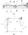
FIG. 1 shows the state in which the present invention is installed in a veranda or a balcony in ordinary day without fire risk and used as a safety parapet for preventing falling. -
FIG. 2 shows the state in which the structure of the present invention installed in a veranda or a balcony is converted to be used as a passageway for fire evacuation. -
FIG. 3 is a view from the back of the present invention in ordinary day without fire risk. -
FIG. 4 shows a side folding ascending/descending means folded (stacked) between an outer frame and a wall-fixed frame which are facing each other in ordinary day without fire risk. -
FIG. 5 shows a side folding ascending/descending means unfolded in a straight form when the fire occurs. -
FIG. 6 shows the bottom of the present invention whose structure is converted into a passageway for fire evacuation when the fire occurs. -
FIG. 7 is a view from the sides of the present invention whose structure is converted into a passageway for fire evacuation. -
FIG. 8 shows a reinforcement chain which is installed on the lower of an outer frame and a wall-fixed frame. -
FIG. 9 shows an outer frame locking means equipped to a wall-fixed frame, a locking bar fixing bracket equipped to the outer frame and a locking bar -
FIG. 10 is a view from the above of a locking bar equipped to a locking bar fixing bracket. -
FIG. 11 is a view from the side of a locking bar equipped to a locking bar fixing bracket. -
FIG. 12 shows an outer frame locking means holding a locking bar. -
FIG. 13 shows the state of a locking bar escaped from an outer frame locking means. -
FIG. 14 is a front view of an upper evacuation structure converting means. -
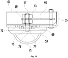
FIG. 15 is a sectional view cut in the transverse direction of an upper evacuation structure converting means. -
FIG. 16 is a sectional view cut in the longitudinal direction of an upper evacuation structure converting means. -
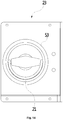
FIG. 17 is a view of the present invention from the inside of the building in ordinary day without fire risk. -
FIG. 18 is a view of the present invention from the inside of the building when the structure of the present invention is converted into a passageway for fire evacuation when the fire occurs. -
- 1: a wall-fixed frame
- 3: an outer frame
- 5: a first side wall
- 7: a second side wall
- 9: a side folding ascending/descending means
- 11. a first lower board
- 13: a second lower board
- 15: a lower folding foothold
- 17: an emergency exit
- 19: a folding emergency exit opening and closing means
- 21: an upper handle
- 23: an upper evacuation structure converting means
- 25: a lower handle
- 27: a lower evacuation structure converting means
- 29: a reinforcement chain
- 31: a first opening and closing door
- 33: a second opening and closing door
- 35: an opening and closing door hinge
- 37: a stopping board
- 39: a lower shock absorber
- 41: a "⊏" shaped knob
- 43: a locking bar fixing bracket
- 45: a locking bar
- 47: a hanging hook
- 49: an outer frame locking means
- 51: an upper shock absorber
- 53: a handle bundle
- 55: a handle bracket
- 57: a rotating bolt
- 59: a first nut
- 61: a lever
- 63: a second nut
- 65: a wire
- 67: a handle cover
- 69: a circular hole
- 71: a circular groove
- 73: a first rotating bolt through-hole
- 75: an inner rotating plate
- 77: an outer rotating plate
- Hereinafter, the present invention is explained in detailed with reference to the attached drawings.
- As seen in figures no 1 to 7, a fire/disaster evacuation facility for building according to the present invention comprises a wall-fixed frame (1) which is fixedly installed on an outer wall of a building facing against a balcony or veranda of the building as a square frame shape; an outer frame (3) which is installed in front of the wall-fixed frame (1) as a front closed square frame shape; a side folding ascending/descending means (9) which comprises a pair of a first side wall (5) and a second side wall (7) which are installed in right and left sides of the wall-fixed frame (1) and the outer frame (3), and are folded or unfolded with hinge-combination, wherein front upper and lower sides of the first side wall (5) are axially fixed to the outer frame (3), and rear upper and lower sides of the second side wall (7) are axially fixed to the wall-fixed frame (1); a lower folding foothold (15) which comprises a first lower board (11) and a second lower board (13) which are installed under the wall-fixed frame (1) and the outer frame (3), and are folded or unfolded with hinge-combined, wherein front upper and lower sides of the first lower board (11) is axially fixed to the outer frame (3), rear upper and lower sides of the second lower board (13) is axially fixed to the wall-fixed frame (1); an emergency exit (17) which enables a man to move to a lower floor through the lower folding foothold (15) when a fire occurs; a folding emergency exit opening and closing means (19) which opens or closes the exit (17) by opening or closing in an installed state to the emergency exit (17), and is folded according to the lower folding foothold (15) when the lower folding foothold (15) is folded, and is unfolded according to the lower folding foothold (15) when the lower folding foothold (15) is unfolded; an upper evacuation structure converting means (23) which provides an evacuation passageway by unfolding the side folding ascending/descending means (9) folded (stacked) between the wall-fixed frame (1) and the outer frame (3), the lower folding foothold (15), and emergency exit opening and closing means (19) according to operating an upper handle (21), when the fire occurs, and, at the same time, by pushing the outer frame (3) to a front of a high-rise building; and
a lower evacuation structure converting means (27) which provides an evacuation passageway by unfolding the side folding ascending/descending means (9) folded (stacked) between the outer frame (3) and the wall-fixed frame (1) installed on the lower floor, the lower folding foothold (15), and the folding emergency exit opening and closing means (19) according to operating a lower handle (25) and, at the same time, by pushing the outer frame (3) installed on the lower floor to the front of the building when the fire or disaster occurs;
the side folding ascending/descending means (9) and the lower folding foothold (15) and the folding emergency exit opening and closing means (19) are stacked between the wall-fixed frame (1) and the outer frame (3) and are used for a safety parapet for preventing falling in ordinary day in a state that the wall-fixed frame (1) and the outer frame (3) face against each other, when the fire or disaster occurs, if the upper and lower handles (21, 25) are operated, the lower folding foothold (15) and the folding emergency exit opening and closing means (19), and the side folding ascending/descending means (9) which are structurally converted to the fire or disaster evacuation, and which are stacked by the upper and lower evacuation structure converting means (23, 27), and which are installed on the current floor and the lower floor, are unfolded, at the same time, and the outer frame (3) moves to the front of the building; wherein an evacuating person opens the folding emergency exit opening and closing means (19) installed on the current floor and then shelters him/herself from the fire or disaster by performing moving process in a direction of the emergency exit (17) of the lower floor through the emergency exit (17). - The first side wall (5) and the second side wall (7) installed to opens the folding emergency exit opening and closing means (19) are processed in a frame shaping a ladder form thus a man who evacuates from the fire or disaster can move to the lower floor by riding on the first side wall (5) and the second side wall (7).
- As seen in
Figure 6 , the folding emergency exit opening and closing means (19) comprises a first opening and closing door (31) which blocks the emergency exit (17) penetrating the first lower board (11) and is hinge-combined to a front edge of the emergency exit (17), a second opening and closing door (33) which blocks the emergency exit (17) penetrating the second lower board (13), and an opening and closing door hinge (35) which connects the first opening and closing door (31) and the second opening and closing door (33). - The opening and closing door hinge (35) is placed on a continuous line with a hinge equipped to the lower folding foothold (15) and the first opening and closing door (31) and the second opening and closing door (33) are folded or unfolded according to the lower folding foothold (15).
- Also, a stopping board (37) is additionally attached on an edge of the second opening and closing door (33) coming into contact with the emergency exit (17), so that the stopping board is projected in a backward of the second opening and closing door (33) from the second opening and closing door (33) and hangs on an edge of the emergency exit (17) and prevent the second opening and closing door (33) from being axially rotated in a downward direction of the emergency exit (17) when the second opening and closing door (33) blocks the emergency exit (17).
- Also, a lower shock absorber (39) is equipped, whose one end is axially fixed to the first opening and closing door (31) and the other end is axially fixed to the first lower board (11) and pushes up an open folding emergency exit opening and closing means (19) with a power between the first lower board (11) and the first opening and closing door (31).
- Also, a "⊏" shaped knob (41) is equipped on an upper side of the second opening and closing door (33).
- As seen in
Figure 8 , both lower sides of the wall fixed frame (1) spaced by a predetermined height from the side folding ascending/descending means (9) is mounted with a reinforcement chain (29) connecting the wall fixed frame (1) and the outer frame (3). - As seen in
Figures 4 ,9 to 13 , the upper evacuation structure converting means (23) comprises a locking bar fixing bracket (43) that is fixedly equipped to an upper side of the outer frame (3) and is projected in a direction of the wall-fixed frame (1), a locking bar (45) whose upper side is fixed and installed to a lower rear side of the locking bar fixing bracket (43) as a straight bar standing in a vertical direction, an outer frame locking means (49) that comprises a hanging hook (47) which when facing the locking bar (45), the locking bar (45) is fixed over and which is interlocked with the upper handle (21) and is elastically shaft-rotated according to operation of the upper handler (21) and releases the held locking bar (45), and that is equipped to the upper side of the wall-fixed frame (1) facing the locking bar (45), and a pair of upper shock absorber (51) whose one end is axially fixed to the upper side of the wall-fixed frame (1) and whose the other end is fixed to the second side wall (7) of the side folding ascending/descending means (9) installed to left or right side of the wall-fixed frame (1) so that if the locking bar (45) escapes from the hanging hook (47) which pushes the second side wall (7) shaft-rotating and coming into contact with the wall-fixed frame (1) to move the outer frame (3) forward, at the same time, and unfolds the side folding ascending/descending means (9), the lower folding foothold (15) and the folding emergency opening and closing means (19) that are folded. - As seen in
Figures 14 to 16 , the upper evacuation structure converting means (23) comprises a handle bundle (53) which is equipped with the upper handle (21) shaft-rotating clockwise or counterclockwise on a front, a handle bracket (55) which is equipped to a rear side of the handle bundle (53), a rotating volt (57) which passes through the handle bracket (55), extends to a rear of the handle bundle (53) and rotates according to the upper handle (21), a first nut (59) which fastens to the rotating volt (57), a lever (61) of which one side is penetrated and fixed to the rotating volt (57), and rotates according to the rotating volt (57) as a bar shape, a second nut (63) which holds the lever (61) fastened to the rotating volt (57) and inserted to the rotating volt (57) with the first nut (59), a wire (65) of which one side is fixed to the other side of the lever (61) and of which the other end is connected with the outer frame locking means (49), and a handle cover (67) which covers the handle bracket (55) equipped with the rotating volt (57), the first nut (59), the lever (61), the second nut (63), and the wire (65), wherein if the upper handle (21) is rotated in any direction, the wire (61) which is connected to the lever (61) is pulled, wherein the hanging hook (47) prepared to the outer frame locking means (49) is shaft-rotated by the pulled wire (65), at the same time, and releases the locking bar (45) which is held. - As seen in
Figure 15 , the handle bracket (55) is penetrated a circular hole (69) forming concentric with the rotating bolt (57), and a rear side of the handle bundle (53) is formed a circular groove (71) concentric with the circular hole (69), the circular groove (71) is inserted an inner rotating plate (75) through which a first rotating bolt through-hole (73), through which the rotating bolt (57) is penetrated, is penetrated, as a shape of rotating plate, and an outer rotating plate (77), which is combined with the inner rotating plate (75) via a bolt and which is inserted to the circular groove (71) and in whose center the rotating bolt (57) is penetrated and connected, sits on the inner rotating plate (75), as a shape of rotating plate. The inner rotating plate (75) and the outer rotating plate (77) distributes the weight applied to the rotating bolt (57), and at the same time, prevents the rotation center of the rotating bolt (57) from being disturbed. - The lower evacuation structure converting means (27) is the same as the upper evacuation structure converting means (23) in terms of general structure except that the locking
bar 45, which is held by the hanging hook (47) installed on the lower floor when the lower handle (25) is operated, comes out from the hanging hook (47), therefore its detailed description is omitted. - Referring to
FIGS. 1 to 18 , a process of operating a fire/disaster evacuation facility in a building according to the present invention having the structure as described above is as follows. - When a fire occurs inside a high-rise building and the upper handle (21) and the lower handle (25) are operated, the locking bar (45) installed on the current floor and the lower floor is released from the hanging hook (47).
- In addition, the upper shock absorber (51) installed on the current layer and the lower layer pushes the second side wall (7), and the first side wall (5) and the second side wall (7) are unfolded in a straight line shape and at the same time moves the outer frame (3) forward, the first lower plate (11), the second lower plate (13), and the first opening and closing door (31) and the second opening and closing door (33), which were folded, are unfolded in a straight form.
- A man who evacuates from the fire or disaster can move downstairs through the emergency exit (17) by climbing on the first lower plate (11) and the second lower plate (13) that are unfolded, and then lifting up the "⊏" shaped knob (41) mounted on the second opening and closing door (33) thereby opening the
emergency exit 17. - The fire / disaster evacuation facility in a building according to the present invention having such a structure may be used as a safety barrier for preventing fall during normal times without a risk of fire or disaster, and may be changed to a shelter facility for evacuation when a fire or disaster occurs.
Claims (3)
- A fire/disaster evacuation facility for building comprising:a wall-fixed frame (1) which is fixedly installed on an outer wall of a building facing against a balcony or veranda of the building as a square frame shape;an outer frame (3) which is installed in front of the wall-fixed frame (1) as a front closed square frame shape;a side folding ascending/descending means (9) which comprises a pair of a first side wall (5) and a second side wall (7) which are installed in right and left sides of the wall-fixed frame (1) and the outer frame (3), and are folded or unfolded with hinge-combination, wherein front upper and lower sides of the first side wall (5) are axially fixed to the outer frame (3), and rear upper and lower sides of the second side wall (7) are axially fixed to the wall-fixed frame (1);a lower folding foothold (15) which comprises a first lower board (11) and a second lower board (13) which are installed under the wall-fixed frame (1) and the outer frame (3), and are folded or unfolded with hinge-combined, wherein front upper and lower sides of the first lower board (11) is axially fixed to the outer frame (3), rear upper and lower sides of the second lower board (13) is axially fixed to the wall-fixed frame (1);an emergency exit (17) which enables a man to move to a lower floor through the lower folding foothold (15) when a fire or disaster occurs;a folding emergency exit opening and closing means (19) which opens or closes the exit (17) by opening or closing in an installed state to the emergency exit (17), and is folded according to the lower folding foothold (15) when the lower folding foothold (15) is folded, and is unfolded according to the lower folding foothold (15) when the lower folding foothold (15) is unfolded;an upper evacuation structure converting means (23) which provides an evacuation passageway by unfolding the side folding ascending/descending means (9) folded (stacked) between the wall-fixed frame (1) and the outer frame (3), the lower folding foothold (15), and emergency exit opening and closing means (19) according to operating an upper handle (21), when the fire occurs, and, at the same time, by pushing the outer frame (3) to a front of a high-rise building; anda lower evacuation structure converting means (27) which provides an evacuation passageway by unfolding the side folding ascending/descending means (9) folded (stacked) between the outer frame (3) and the wall-fixed frame (1) installed on the lower floor, the lower folding foothold (15), and the folding emergency exit opening and closing means (19) according to operating a lower handle (25) and, at the same time, by pushing the outer frame (3) installed on the lower floor to the front of the building when the fire or disaster occurs;the side folding ascending/descending means (9) and the lower folding foothold (15) and the folding emergency exit opening and closing means (19) are stacked between the wall-fixed frame (1) and the outer frame (3) and are used for a safety parapet for preventing falling in ordinary day in a state that the wall-fixed frame (1) and the outer frame (3) face against each other, when the fire or disaster occurs, if the upper and lower handles (21, 25) are operated, the lower folding foothold (15) and the folding emergency exit opening and closing means (19), and the side folding ascending/descending means (9) which are structurally converted to the fire evacuation, and which are stacked by the upper and lower evacuation structure converting means (23, 27), and which are installed on the current floor and the lower floor, are unfolded, at the same time, and the outer frame (3) moves to the front of the building;wherein an evacuating person opens the folding emergency exit opening and closing means (19) installed on the current floor and then shelters him/herself from the fire or disaster by performing moving process in a direction of the emergency exit (17) of the lower floor through the emergency exit (17);wherein the folding emergency exit opening and closing means (19) comprisinga first opening and closing door (31) which blocks the emergency exit (17) penetrating the first lower board (11) and is hinge-combined to a front edge of the emergency exit (17),a second opening and closing door (33) which blocks the emergency exit (17) penetrating the second lower board (13), andan opening and closing door hinge (35) which connects the first opening and closing door (31) and the second opening and closing door (33);wherein the opening and closing door hinge (35) is placed on a continuous line with a hinge equipped to the lower folding foothold (15) and the first opening and closing door (31) and the second opening and closing door (33) are folded or unfolded according to the lower folding foothold (15);wherein a stopping board (37) is additionally attached on an edge of the second opening and closing door (33) coming into contact with the emergency exit (17), so that the stopping board is projected in a backward of the second opening and closing door (33) from the second opening and closing door (33) and hangs on an edge of the emergency exit (17) and prevent the second opening and closing door (33) from being axially rotated in a downward direction of the emergency exit (17) when the second opening and closing door (33) blocks the emergency exit (17);wherein a lower shock absorber (39) is equipped, whose one end is axially fixed to the first opening and closing door (31) and the other end is axially fixed to the first lower board (11) and pushes up an open folding emergency exit opening and closing means (19) with a power between the first lower board (11) and the first opening and closing door (31);a "⊏" shaped knob (41) is equipped on an upper side of the second opening and closing door (33).
- The fire/disaster evacuation facility for building according to claim 1,
wherein the upper evacuation structure converting means (23) comprises:a locking bar fixing bracket (43) that is fixedly equipped to an upper side of the outer frame (3) and is projected in a direction of the wall-fixed frame (1),a locking bar (45) whose upper side is fixed and installed to a lower rear side of the locking bar fixing bracket (43) as a straight bar standing in a vertical direction,an outer frame locking means (49) that comprises a hanging hook (47) which when facing the locking bar (45), the locking bar (45) is fixed over and which is interlocked with the upper handle (21) and is elastically shaft-rotated according to operation of the upper handler (21) and releases the held locking bar (45), and that is equipped to the upper side of the wall-fixed frame (1) facing the locking bar (45), anda pair of upper shock absorber (51) whose one end is axially fixed to the upper side of the wall-fixed frame (1) and whose the other end is fixed to the second side wall (7) of the side folding ascending/descending means (9) installed to left or right side of the wall-fixed frame (1) so that if the locking bar (45) escapes from the hanging hook (47) which pushes the second side wall (7) shaft-rotating and coming into contact with the wall-fixed frame (1) to move the outer frame (3) forward, at the same time, and unfolds the side folding ascending/descending means (9), the lower folding foothold (15) and the folding emergency opening and closing means (19) that are folded. - The fire/disaster evacuation facility for building according to claim 2,
wherein the upper evacuation structure converting means (23) comprises
a handle bundle (53) which is equipped with the upper handle (21) shaft-rotating clockwise or counterclockwise on a front,
a handle bracket (55) which is equipped to a rear side of the handle bundle (53),
a rotating volt (57) which passes through the handle bracket (55), extends to a rear of the handle bundle (53) and rotates according to the upper handle (21),
a first nut (59) which fastens to the rotating volt (57),
a lever (61) of which one side is penetrated and fixed to the rotating volt (57), and rotates according to the rotating volt (57) as a bar shape,
a second nut (63) which holds the lever (61) fastened to the rotating volt (57) and inserted to the rotating volt (57) with the first nut (59),
a wire (65) of which one side is fixed to the other side of the lever (61) and of which the other end is connected with the outer frame locking means (49), and
a handle cover (67) which covers the handle bracket (55) equipped with the rotating volt (57), the first nut (59), the lever (61), the second nut (63), and the wire (65),
wherein if the upper handle (21) is rotated in any direction, the wire (61) which is connected to the lever (61) is pulled,
wherein the hanging hook (47) prepared to the outer frame locking means (49) is shaft-rotated by the pulled wire (65), at the same time, and releases the locking bar (45) which is held.
Applications Claiming Priority (2)
| Application Number | Priority Date | Filing Date | Title |
|---|---|---|---|
| KR1020170076740A KR101782139B1 (en) | 2017-06-16 | 2017-06-16 | Fire and disaster escaping system in a structure |
| PCT/KR2018/004824 WO2018230837A1 (en) | 2017-06-16 | 2018-04-26 | Fire/disaster evacuation facility for building |
Publications (3)
| Publication Number | Publication Date |
|---|---|
| EP3639896A1 true EP3639896A1 (en) | 2020-04-22 |
| EP3639896A4 EP3639896A4 (en) | 2021-03-10 |
| EP3639896B1 EP3639896B1 (en) | 2022-05-11 |
Family
ID=60139864
Family Applications (1)
| Application Number | Title | Priority Date | Filing Date |
|---|---|---|---|
| EP18818328.9A Active EP3639896B1 (en) | 2017-06-16 | 2018-04-26 | Fire/disaster evacuation facility for building |
Country Status (6)
| Country | Link |
|---|---|
| EP (1) | EP3639896B1 (en) |
| JP (1) | JP6949147B2 (en) |
| KR (1) | KR101782139B1 (en) |
| CN (1) | CN110799250B (en) |
| ES (1) | ES2920530T3 (en) |
| WO (1) | WO2018230837A1 (en) |
Families Citing this family (8)
| Publication number | Priority date | Publication date | Assignee | Title |
|---|---|---|---|---|
| KR101975737B1 (en) * | 2019-01-17 | 2019-05-07 | 김주미 | The fire escaping apparatus using a gallery window in the high building |
| KR102005216B1 (en) * | 2019-03-26 | 2019-07-29 | 김주미 | The fire escaping apparatus in high buildings |
| KR102096210B1 (en) * | 2019-06-10 | 2020-04-01 | 정성용 | Emergency evacuation device installed on outer wall of building |
| KR102422366B1 (en) * | 2020-02-14 | 2022-07-20 | 한국철도기술연구원 | Box type carrier and evacuating system having the box type carrier |
| KR102141719B1 (en) * | 2020-03-31 | 2020-08-05 | 김동우 | An apparatus for escaping fire and disaster in a structure |
| CN113006440B (en) * | 2021-02-26 | 2022-10-25 | 中建二局第一建筑工程有限公司 | Portable quick installation operation platform of assembled steel construction frame component |
| CN115246345B (en) * | 2022-09-01 | 2023-09-22 | 北京城建设计发展集团股份有限公司 | Method for arranging double contact net upright posts on inner side of U-shaped beam line |
| CN116196566B (en) * | 2023-01-10 | 2023-10-03 | 宿迁市应急管理局 | High-rise fire disaster self-rescue device and rescue method thereof |
Family Cites Families (17)
| Publication number | Priority date | Publication date | Assignee | Title |
|---|---|---|---|---|
| JPS5340958Y2 (en) * | 1974-11-29 | 1978-10-03 | ||
| DE2949429C2 (en) * | 1979-12-08 | 1985-06-05 | Walther & Cie AG, 5000 Köln | Rescue system on high-rise buildings for rescuing people in the event of a fire |
| JPH10266250A (en) * | 1997-03-28 | 1998-10-06 | Yoshitsugu Hirano | Large rectangular iron cover |
| JP2003265633A (en) * | 2002-03-15 | 2003-09-24 | Matsumoto Kiko Kk | Escape equipment |
| KR100476536B1 (en) * | 2004-07-03 | 2005-03-17 | (주)아이 에스 피 엘 | Life saving, implement |
| CN2794548Y (en) * | 2005-06-03 | 2006-07-12 | 董绍付 | Emergency escaping path for high rise building |
| KR100968162B1 (en) * | 2010-03-12 | 2010-07-06 | 박기한 | Staircase for blaze evacuation is security equipment of installation to building veranda |
| KR101191757B1 (en) * | 2010-10-01 | 2012-10-16 | (주)아이 에스 피 엘 | NON-ELECTRIC MANY PEOPLE´s LIFE ESCAPING FACILITIES when a fire in a high-rise building or an apartmentNON-ELECTRIC FOLDING ESCAPING DECK in storage |
| KR101148128B1 (en) * | 2011-03-23 | 2012-05-23 | 에스제이테크윈(주) | The under type of emergency escaping equipment for building |
| KR101188140B1 (en) | 2011-05-12 | 2012-10-08 | 류순모 | An apparatus for opening and shutting the manhole for escaping the fire place in the high building |
| KR101055294B1 (en) * | 2011-06-22 | 2011-08-09 | (주) 크로텍 | The installation to evacuating from a fire |
| CN104329006B (en) * | 2014-10-19 | 2016-02-24 | 衢州图艺工业设计有限公司 | A kind of lifting theft-proof window |
| CN104667441B (en) * | 2015-02-04 | 2022-05-24 | 高留中 | Folding escape box for storied building |
| CN204543299U (en) * | 2015-02-04 | 2015-08-12 | 高留中 | Building folding escape case |
| KR101562205B1 (en) * | 2015-05-22 | 2015-10-23 | 주식회사 에스엠텍 | Safety system for escaping the fire place in the high building |
| KR101793332B1 (en) * | 2015-09-01 | 2017-11-02 | 오현석 | Emergency Escape Apparatus |
| CN205618061U (en) * | 2016-04-18 | 2016-10-05 | 李钢 | Protection network of fleing |
-
2017
- 2017-06-16 KR KR1020170076740A patent/KR101782139B1/en active IP Right Grant
-
2018
- 2018-04-26 EP EP18818328.9A patent/EP3639896B1/en active Active
- 2018-04-26 WO PCT/KR2018/004824 patent/WO2018230837A1/en unknown
- 2018-04-26 CN CN201880040135.7A patent/CN110799250B/en active Active
- 2018-04-26 ES ES18818328T patent/ES2920530T3/en active Active
- 2018-04-26 JP JP2019569467A patent/JP6949147B2/en active Active
Also Published As
| Publication number | Publication date |
|---|---|
| KR101782139B1 (en) | 2017-10-12 |
| CN110799250B (en) | 2020-11-10 |
| JP6949147B2 (en) | 2021-10-13 |
| CN110799250A (en) | 2020-02-14 |
| ES2920530T3 (en) | 2022-08-05 |
| EP3639896A4 (en) | 2021-03-10 |
| WO2018230837A1 (en) | 2018-12-20 |
| EP3639896B1 (en) | 2022-05-11 |
| JP2020523507A (en) | 2020-08-06 |
Similar Documents
| Publication | Publication Date | Title |
|---|---|---|
| EP3639896B1 (en) | Fire/disaster evacuation facility for building | |
| KR101562205B1 (en) | Safety system for escaping the fire place in the high building | |
| CN108368702B (en) | Integrated folding safety rail and outdoor refuge stair | |
| KR101706609B1 (en) | A safety dvice and emergency escape device for high-rise building | |
| KR101962656B1 (en) | Disaster Escaping System Equipped with Gate for Skyscraper | |
| KR101843842B1 (en) | Fire and disaster escaping system combined using for balcony balustrade | |
| KR101684335B1 (en) | Railing features provided by the refuge | |
| US11549310B2 (en) | Foldable balcony balustrade-combined fire/disaster evacuation facility | |
| KR101030286B1 (en) | An apparatus for escaping emergency having a boarding structure using exclusively in a balustrade of veranda | |
| KR101903545B1 (en) | The fire and disaster escaping system in a high-rise building | |
| KR101412211B1 (en) | The safe railing which possessed a refuge function for apartment | |
| KR20110004264A (en) | Eemergency escaping apparatus of a layer space | |
| KR20100092175A (en) | Fire escape apparatus | |
| KR100613880B1 (en) | Emergency shelter device using a handrail balcony | |
| KR20070060646A (en) | Ladder structure for emergency escape from building | |
| KR101131484B1 (en) | Escaping apparatus for emergency evacuation | |
| KR101161561B1 (en) | A Safety Guardrail on Which a Rotary Type Rescue Ladder is Attached | |
| KR102085587B1 (en) | Folding Evacuation Apparatus | |
| KR20160143606A (en) | Escape ladder for emergency | |
| KR101648354B1 (en) | Folding handrail having slow descending function of apartment house | |
| KR20230007700A (en) | A downward tunnel type ladder for evacuation | |
| RU88274U1 (en) | FIRE RESCUE COMPLEX | |
| KR200378175Y1 (en) | Emergency shelter device using a handrail balcony | |
| KR101105685B1 (en) | Descending device for fire escape | |
| KR20110083820A (en) | A safety guardrail on which a rotary type fire rescue ladder attached |
Legal Events
| Date | Code | Title | Description |
|---|---|---|---|
| STAA | Information on the status of an ep patent application or granted ep patent |
Free format text: STATUS: THE INTERNATIONAL PUBLICATION HAS BEEN MADE |
|
| PUAI | Public reference made under article 153(3) epc to a published international application that has entered the european phase |
Free format text: ORIGINAL CODE: 0009012 |
|
| STAA | Information on the status of an ep patent application or granted ep patent |
Free format text: STATUS: REQUEST FOR EXAMINATION WAS MADE |
|
| 17P | Request for examination filed |
Effective date: 20200115 |
|
| AK | Designated contracting states |
Kind code of ref document: A1 Designated state(s): AL AT BE BG CH CY CZ DE DK EE ES FI FR GB GR HR HU IE IS IT LI LT LU LV MC MK MT NL NO PL PT RO RS SE SI SK SM TR |
|
| AX | Request for extension of the european patent |
Extension state: BA ME |
|
| DAV | Request for validation of the european patent (deleted) | ||
| DAX | Request for extension of the european patent (deleted) | ||
| A4 | Supplementary search report drawn up and despatched |
Effective date: 20210208 |
|
| RIC1 | Information provided on ipc code assigned before grant |
Ipc: E04F 11/18 20060101ALI20210202BHEP Ipc: A62B 5/00 20060101ALI20210202BHEP Ipc: A62B 1/02 20060101AFI20210202BHEP |
|
| STAA | Information on the status of an ep patent application or granted ep patent |
Free format text: STATUS: EXAMINATION IS IN PROGRESS |
|
| RIC1 | Information provided on ipc code assigned before grant |
Ipc: A62B 1/02 20060101AFI20210614BHEP Ipc: E04F 11/18 20060101ALI20210614BHEP Ipc: A62B 5/00 20060101ALI20210614BHEP |
|
| 17Q | First examination report despatched |
Effective date: 20210628 |
|
| GRAP | Despatch of communication of intention to grant a patent |
Free format text: ORIGINAL CODE: EPIDOSNIGR1 |
|
| STAA | Information on the status of an ep patent application or granted ep patent |
Free format text: STATUS: GRANT OF PATENT IS INTENDED |
|
| GRAS | Grant fee paid |
Free format text: ORIGINAL CODE: EPIDOSNIGR3 |
|
| GRAA | (expected) grant |
Free format text: ORIGINAL CODE: 0009210 |
|
| STAA | Information on the status of an ep patent application or granted ep patent |
Free format text: STATUS: THE PATENT HAS BEEN GRANTED |
|
| INTG | Intention to grant announced |
Effective date: 20220321 |
|
| AK | Designated contracting states |
Kind code of ref document: B1 Designated state(s): AL AT BE BG CH CY CZ DE DK EE ES FI FR GB GR HR HU IE IS IT LI LT LU LV MC MK MT NL NO PL PT RO RS SE SI SK SM TR |
|
| REG | Reference to a national code |
Ref country code: GB Ref legal event code: FG4D |
|
| REG | Reference to a national code |
Ref country code: CH Ref legal event code: EP |
|
| REG | Reference to a national code |
Ref country code: AT Ref legal event code: REF Ref document number: 1490882 Country of ref document: AT Kind code of ref document: T Effective date: 20220515 |
|
| REG | Reference to a national code |
Ref country code: DE Ref legal event code: R096 Ref document number: 602018035556 Country of ref document: DE |
|
| REG | Reference to a national code |
Ref country code: IE Ref legal event code: FG4D |
|
| REG | Reference to a national code |
Ref country code: ES Ref legal event code: FG2A Ref document number: 2920530 Country of ref document: ES Kind code of ref document: T3 Effective date: 20220805 |
|
| REG | Reference to a national code |
Ref country code: LT Ref legal event code: MG9D |
|
| REG | Reference to a national code |
Ref country code: NL Ref legal event code: MP Effective date: 20220511 |
|
| REG | Reference to a national code |
Ref country code: AT Ref legal event code: MK05 Ref document number: 1490882 Country of ref document: AT Kind code of ref document: T Effective date: 20220511 |
|
| PG25 | Lapsed in a contracting state [announced via postgrant information from national office to epo] |
Ref country code: SE Free format text: LAPSE BECAUSE OF FAILURE TO SUBMIT A TRANSLATION OF THE DESCRIPTION OR TO PAY THE FEE WITHIN THE PRESCRIBED TIME-LIMIT Effective date: 20220511 Ref country code: PT Free format text: LAPSE BECAUSE OF FAILURE TO SUBMIT A TRANSLATION OF THE DESCRIPTION OR TO PAY THE FEE WITHIN THE PRESCRIBED TIME-LIMIT Effective date: 20220912 Ref country code: NO Free format text: LAPSE BECAUSE OF FAILURE TO SUBMIT A TRANSLATION OF THE DESCRIPTION OR TO PAY THE FEE WITHIN THE PRESCRIBED TIME-LIMIT Effective date: 20220811 Ref country code: NL Free format text: LAPSE BECAUSE OF FAILURE TO SUBMIT A TRANSLATION OF THE DESCRIPTION OR TO PAY THE FEE WITHIN THE PRESCRIBED TIME-LIMIT Effective date: 20220511 Ref country code: LT Free format text: LAPSE BECAUSE OF FAILURE TO SUBMIT A TRANSLATION OF THE DESCRIPTION OR TO PAY THE FEE WITHIN THE PRESCRIBED TIME-LIMIT Effective date: 20220511 Ref country code: HR Free format text: LAPSE BECAUSE OF FAILURE TO SUBMIT A TRANSLATION OF THE DESCRIPTION OR TO PAY THE FEE WITHIN THE PRESCRIBED TIME-LIMIT Effective date: 20220511 Ref country code: GR Free format text: LAPSE BECAUSE OF FAILURE TO SUBMIT A TRANSLATION OF THE DESCRIPTION OR TO PAY THE FEE WITHIN THE PRESCRIBED TIME-LIMIT Effective date: 20220812 Ref country code: FI Free format text: LAPSE BECAUSE OF FAILURE TO SUBMIT A TRANSLATION OF THE DESCRIPTION OR TO PAY THE FEE WITHIN THE PRESCRIBED TIME-LIMIT Effective date: 20220511 Ref country code: BG Free format text: LAPSE BECAUSE OF FAILURE TO SUBMIT A TRANSLATION OF THE DESCRIPTION OR TO PAY THE FEE WITHIN THE PRESCRIBED TIME-LIMIT Effective date: 20220811 Ref country code: AT Free format text: LAPSE BECAUSE OF FAILURE TO SUBMIT A TRANSLATION OF THE DESCRIPTION OR TO PAY THE FEE WITHIN THE PRESCRIBED TIME-LIMIT Effective date: 20220511 |
|
| PG25 | Lapsed in a contracting state [announced via postgrant information from national office to epo] |
Ref country code: RS Free format text: LAPSE BECAUSE OF FAILURE TO SUBMIT A TRANSLATION OF THE DESCRIPTION OR TO PAY THE FEE WITHIN THE PRESCRIBED TIME-LIMIT Effective date: 20220511 Ref country code: PL Free format text: LAPSE BECAUSE OF FAILURE TO SUBMIT A TRANSLATION OF THE DESCRIPTION OR TO PAY THE FEE WITHIN THE PRESCRIBED TIME-LIMIT Effective date: 20220511 Ref country code: LV Free format text: LAPSE BECAUSE OF FAILURE TO SUBMIT A TRANSLATION OF THE DESCRIPTION OR TO PAY THE FEE WITHIN THE PRESCRIBED TIME-LIMIT Effective date: 20220511 Ref country code: IS Free format text: LAPSE BECAUSE OF FAILURE TO SUBMIT A TRANSLATION OF THE DESCRIPTION OR TO PAY THE FEE WITHIN THE PRESCRIBED TIME-LIMIT Effective date: 20220911 |
|
| PG25 | Lapsed in a contracting state [announced via postgrant information from national office to epo] |
Ref country code: SM Free format text: LAPSE BECAUSE OF FAILURE TO SUBMIT A TRANSLATION OF THE DESCRIPTION OR TO PAY THE FEE WITHIN THE PRESCRIBED TIME-LIMIT Effective date: 20220511 Ref country code: SK Free format text: LAPSE BECAUSE OF FAILURE TO SUBMIT A TRANSLATION OF THE DESCRIPTION OR TO PAY THE FEE WITHIN THE PRESCRIBED TIME-LIMIT Effective date: 20220511 Ref country code: RO Free format text: LAPSE BECAUSE OF FAILURE TO SUBMIT A TRANSLATION OF THE DESCRIPTION OR TO PAY THE FEE WITHIN THE PRESCRIBED TIME-LIMIT Effective date: 20220511 Ref country code: EE Free format text: LAPSE BECAUSE OF FAILURE TO SUBMIT A TRANSLATION OF THE DESCRIPTION OR TO PAY THE FEE WITHIN THE PRESCRIBED TIME-LIMIT Effective date: 20220511 Ref country code: DK Free format text: LAPSE BECAUSE OF FAILURE TO SUBMIT A TRANSLATION OF THE DESCRIPTION OR TO PAY THE FEE WITHIN THE PRESCRIBED TIME-LIMIT Effective date: 20220511 Ref country code: CZ Free format text: LAPSE BECAUSE OF FAILURE TO SUBMIT A TRANSLATION OF THE DESCRIPTION OR TO PAY THE FEE WITHIN THE PRESCRIBED TIME-LIMIT Effective date: 20220511 |
|
| REG | Reference to a national code |
Ref country code: DE Ref legal event code: R097 Ref document number: 602018035556 Country of ref document: DE |
|
| PLBE | No opposition filed within time limit |
Free format text: ORIGINAL CODE: 0009261 |
|
| STAA | Information on the status of an ep patent application or granted ep patent |
Free format text: STATUS: NO OPPOSITION FILED WITHIN TIME LIMIT |
|
| PG25 | Lapsed in a contracting state [announced via postgrant information from national office to epo] |
Ref country code: AL Free format text: LAPSE BECAUSE OF FAILURE TO SUBMIT A TRANSLATION OF THE DESCRIPTION OR TO PAY THE FEE WITHIN THE PRESCRIBED TIME-LIMIT Effective date: 20220511 |
|
| 26N | No opposition filed |
Effective date: 20230214 |
|
| PG25 | Lapsed in a contracting state [announced via postgrant information from national office to epo] |
Ref country code: SI Free format text: LAPSE BECAUSE OF FAILURE TO SUBMIT A TRANSLATION OF THE DESCRIPTION OR TO PAY THE FEE WITHIN THE PRESCRIBED TIME-LIMIT Effective date: 20220511 |
|
| REG | Reference to a national code |
Ref country code: CH Ref legal event code: PL |
|
| PG25 | Lapsed in a contracting state [announced via postgrant information from national office to epo] |
Ref country code: LU Free format text: LAPSE BECAUSE OF NON-PAYMENT OF DUE FEES Effective date: 20230426 |
|
| REG | Reference to a national code |
Ref country code: BE Ref legal event code: MM Effective date: 20230430 |
|
| PG25 | Lapsed in a contracting state [announced via postgrant information from national office to epo] |
Ref country code: MC Free format text: LAPSE BECAUSE OF FAILURE TO SUBMIT A TRANSLATION OF THE DESCRIPTION OR TO PAY THE FEE WITHIN THE PRESCRIBED TIME-LIMIT Effective date: 20220511 |
|
| PG25 | Lapsed in a contracting state [announced via postgrant information from national office to epo] |
Ref country code: MC Free format text: LAPSE BECAUSE OF FAILURE TO SUBMIT A TRANSLATION OF THE DESCRIPTION OR TO PAY THE FEE WITHIN THE PRESCRIBED TIME-LIMIT Effective date: 20220511 Ref country code: LI Free format text: LAPSE BECAUSE OF NON-PAYMENT OF DUE FEES Effective date: 20230430 Ref country code: IT Free format text: LAPSE BECAUSE OF FAILURE TO SUBMIT A TRANSLATION OF THE DESCRIPTION OR TO PAY THE FEE WITHIN THE PRESCRIBED TIME-LIMIT Effective date: 20220511 Ref country code: CH Free format text: LAPSE BECAUSE OF NON-PAYMENT OF DUE FEES Effective date: 20230430 |
|
| REG | Reference to a national code |
Ref country code: IE Ref legal event code: MM4A |
|
| PG25 | Lapsed in a contracting state [announced via postgrant information from national office to epo] |
Ref country code: BE Free format text: LAPSE BECAUSE OF NON-PAYMENT OF DUE FEES Effective date: 20230430 |
|
| PG25 | Lapsed in a contracting state [announced via postgrant information from national office to epo] |
Ref country code: IE Free format text: LAPSE BECAUSE OF NON-PAYMENT OF DUE FEES Effective date: 20230426 |
|
| PG25 | Lapsed in a contracting state [announced via postgrant information from national office to epo] |
Ref country code: IE Free format text: LAPSE BECAUSE OF NON-PAYMENT OF DUE FEES Effective date: 20230426 |
|
| PGFP | Annual fee paid to national office [announced via postgrant information from national office to epo] |
Ref country code: GB Payment date: 20240408 Year of fee payment: 7 |
|
| PGFP | Annual fee paid to national office [announced via postgrant information from national office to epo] |
Ref country code: DE Payment date: 20240405 Year of fee payment: 7 |
|
| PGFP | Annual fee paid to national office [announced via postgrant information from national office to epo] |
Ref country code: ES Payment date: 20240513 Year of fee payment: 7 |
|
| PGFP | Annual fee paid to national office [announced via postgrant information from national office to epo] |
Ref country code: FR Payment date: 20240409 Year of fee payment: 7 |