EP3637459B1 - Aufbewahrungssystem - Google Patents
Aufbewahrungssystem Download PDFInfo
- Publication number
- EP3637459B1 EP3637459B1 EP18801638.0A EP18801638A EP3637459B1 EP 3637459 B1 EP3637459 B1 EP 3637459B1 EP 18801638 A EP18801638 A EP 18801638A EP 3637459 B1 EP3637459 B1 EP 3637459B1
- Authority
- EP
- European Patent Office
- Prior art keywords
- rail
- rails
- unit
- members
- article
- Prior art date
- Legal status (The legal status is an assumption and is not a legal conclusion. Google has not performed a legal analysis and makes no representation as to the accuracy of the status listed.)
- Active
Links
- 239000004065 semiconductor Substances 0.000 description 18
- 238000009434 installation Methods 0.000 description 10
- 238000004519 manufacturing process Methods 0.000 description 6
- 230000000694 effects Effects 0.000 description 5
- 235000012431 wafers Nutrition 0.000 description 5
- 239000011159 matrix material Substances 0.000 description 4
- 230000002787 reinforcement Effects 0.000 description 2
- 229910000831 Steel Inorganic materials 0.000 description 1
- 230000003247 decreasing effect Effects 0.000 description 1
- 239000011521 glass Substances 0.000 description 1
- 238000012986 modification Methods 0.000 description 1
- 230000004048 modification Effects 0.000 description 1
- 239000011295 pitch Substances 0.000 description 1
- 239000010959 steel Substances 0.000 description 1
- 238000004804 winding Methods 0.000 description 1
Images


Classifications
-
- H—ELECTRICITY
- H01—ELECTRIC ELEMENTS
- H01L—SEMICONDUCTOR DEVICES NOT COVERED BY CLASS H10
- H01L21/00—Processes or apparatus adapted for the manufacture or treatment of semiconductor or solid state devices or of parts thereof
- H01L21/67—Apparatus specially adapted for handling semiconductor or electric solid state devices during manufacture or treatment thereof; Apparatus specially adapted for handling wafers during manufacture or treatment of semiconductor or electric solid state devices or components ; Apparatus not specifically provided for elsewhere
- H01L21/677—Apparatus specially adapted for handling semiconductor or electric solid state devices during manufacture or treatment thereof; Apparatus specially adapted for handling wafers during manufacture or treatment of semiconductor or electric solid state devices or components ; Apparatus not specifically provided for elsewhere for conveying, e.g. between different workstations
- H01L21/67703—Apparatus specially adapted for handling semiconductor or electric solid state devices during manufacture or treatment thereof; Apparatus specially adapted for handling wafers during manufacture or treatment of semiconductor or electric solid state devices or components ; Apparatus not specifically provided for elsewhere for conveying, e.g. between different workstations between different workstations
- H01L21/67706—Mechanical details, e.g. roller, belt
-
- B—PERFORMING OPERATIONS; TRANSPORTING
- B65—CONVEYING; PACKING; STORING; HANDLING THIN OR FILAMENTARY MATERIAL
- B65G—TRANSPORT OR STORAGE DEVICES, e.g. CONVEYORS FOR LOADING OR TIPPING, SHOP CONVEYOR SYSTEMS OR PNEUMATIC TUBE CONVEYORS
- B65G1/00—Storing articles, individually or in orderly arrangement, in warehouses or magazines
- B65G1/02—Storage devices
- B65G1/04—Storage devices mechanical
- B65G1/0457—Storage devices mechanical with suspended load carriers
-
- B—PERFORMING OPERATIONS; TRANSPORTING
- B65—CONVEYING; PACKING; STORING; HANDLING THIN OR FILAMENTARY MATERIAL
- B65G—TRANSPORT OR STORAGE DEVICES, e.g. CONVEYORS FOR LOADING OR TIPPING, SHOP CONVEYOR SYSTEMS OR PNEUMATIC TUBE CONVEYORS
- B65G1/00—Storing articles, individually or in orderly arrangement, in warehouses or magazines
- B65G1/02—Storage devices
- B65G1/04—Storage devices mechanical
- B65G1/0464—Storage devices mechanical with access from above
-
- H—ELECTRICITY
- H01—ELECTRIC ELEMENTS
- H01L—SEMICONDUCTOR DEVICES NOT COVERED BY CLASS H10
- H01L21/00—Processes or apparatus adapted for the manufacture or treatment of semiconductor or solid state devices or of parts thereof
- H01L21/67—Apparatus specially adapted for handling semiconductor or electric solid state devices during manufacture or treatment thereof; Apparatus specially adapted for handling wafers during manufacture or treatment of semiconductor or electric solid state devices or components ; Apparatus not specifically provided for elsewhere
- H01L21/67005—Apparatus not specifically provided for elsewhere
- H01L21/67242—Apparatus for monitoring, sorting or marking
- H01L21/67259—Position monitoring, e.g. misposition detection or presence detection
-
- H—ELECTRICITY
- H01—ELECTRIC ELEMENTS
- H01L—SEMICONDUCTOR DEVICES NOT COVERED BY CLASS H10
- H01L21/00—Processes or apparatus adapted for the manufacture or treatment of semiconductor or solid state devices or of parts thereof
- H01L21/67—Apparatus specially adapted for handling semiconductor or electric solid state devices during manufacture or treatment thereof; Apparatus specially adapted for handling wafers during manufacture or treatment of semiconductor or electric solid state devices or components ; Apparatus not specifically provided for elsewhere
- H01L21/673—Apparatus specially adapted for handling semiconductor or electric solid state devices during manufacture or treatment thereof; Apparatus specially adapted for handling wafers during manufacture or treatment of semiconductor or electric solid state devices or components ; Apparatus not specifically provided for elsewhere using specially adapted carriers or holders; Fixing the workpieces on such carriers or holders
-
- H—ELECTRICITY
- H01—ELECTRIC ELEMENTS
- H01L—SEMICONDUCTOR DEVICES NOT COVERED BY CLASS H10
- H01L21/00—Processes or apparatus adapted for the manufacture or treatment of semiconductor or solid state devices or of parts thereof
- H01L21/67—Apparatus specially adapted for handling semiconductor or electric solid state devices during manufacture or treatment thereof; Apparatus specially adapted for handling wafers during manufacture or treatment of semiconductor or electric solid state devices or components ; Apparatus not specifically provided for elsewhere
- H01L21/677—Apparatus specially adapted for handling semiconductor or electric solid state devices during manufacture or treatment thereof; Apparatus specially adapted for handling wafers during manufacture or treatment of semiconductor or electric solid state devices or components ; Apparatus not specifically provided for elsewhere for conveying, e.g. between different workstations
- H01L21/67703—Apparatus specially adapted for handling semiconductor or electric solid state devices during manufacture or treatment thereof; Apparatus specially adapted for handling wafers during manufacture or treatment of semiconductor or electric solid state devices or components ; Apparatus not specifically provided for elsewhere for conveying, e.g. between different workstations between different workstations
- H01L21/67724—Apparatus specially adapted for handling semiconductor or electric solid state devices during manufacture or treatment thereof; Apparatus specially adapted for handling wafers during manufacture or treatment of semiconductor or electric solid state devices or components ; Apparatus not specifically provided for elsewhere for conveying, e.g. between different workstations between different workstations by means of a cart or a vehicule
-
- H—ELECTRICITY
- H01—ELECTRIC ELEMENTS
- H01L—SEMICONDUCTOR DEVICES NOT COVERED BY CLASS H10
- H01L21/00—Processes or apparatus adapted for the manufacture or treatment of semiconductor or solid state devices or of parts thereof
- H01L21/67—Apparatus specially adapted for handling semiconductor or electric solid state devices during manufacture or treatment thereof; Apparatus specially adapted for handling wafers during manufacture or treatment of semiconductor or electric solid state devices or components ; Apparatus not specifically provided for elsewhere
- H01L21/677—Apparatus specially adapted for handling semiconductor or electric solid state devices during manufacture or treatment thereof; Apparatus specially adapted for handling wafers during manufacture or treatment of semiconductor or electric solid state devices or components ; Apparatus not specifically provided for elsewhere for conveying, e.g. between different workstations
- H01L21/67703—Apparatus specially adapted for handling semiconductor or electric solid state devices during manufacture or treatment thereof; Apparatus specially adapted for handling wafers during manufacture or treatment of semiconductor or electric solid state devices or components ; Apparatus not specifically provided for elsewhere for conveying, e.g. between different workstations between different workstations
- H01L21/67733—Overhead conveying
-
- H—ELECTRICITY
- H01—ELECTRIC ELEMENTS
- H01L—SEMICONDUCTOR DEVICES NOT COVERED BY CLASS H10
- H01L21/00—Processes or apparatus adapted for the manufacture or treatment of semiconductor or solid state devices or of parts thereof
- H01L21/67—Apparatus specially adapted for handling semiconductor or electric solid state devices during manufacture or treatment thereof; Apparatus specially adapted for handling wafers during manufacture or treatment of semiconductor or electric solid state devices or components ; Apparatus not specifically provided for elsewhere
- H01L21/677—Apparatus specially adapted for handling semiconductor or electric solid state devices during manufacture or treatment thereof; Apparatus specially adapted for handling wafers during manufacture or treatment of semiconductor or electric solid state devices or components ; Apparatus not specifically provided for elsewhere for conveying, e.g. between different workstations
- H01L21/67703—Apparatus specially adapted for handling semiconductor or electric solid state devices during manufacture or treatment thereof; Apparatus specially adapted for handling wafers during manufacture or treatment of semiconductor or electric solid state devices or components ; Apparatus not specifically provided for elsewhere for conveying, e.g. between different workstations between different workstations
- H01L21/67736—Loading to or unloading from a conveyor
-
- H—ELECTRICITY
- H01—ELECTRIC ELEMENTS
- H01L—SEMICONDUCTOR DEVICES NOT COVERED BY CLASS H10
- H01L21/00—Processes or apparatus adapted for the manufacture or treatment of semiconductor or solid state devices or of parts thereof
- H01L21/67—Apparatus specially adapted for handling semiconductor or electric solid state devices during manufacture or treatment thereof; Apparatus specially adapted for handling wafers during manufacture or treatment of semiconductor or electric solid state devices or components ; Apparatus not specifically provided for elsewhere
- H01L21/677—Apparatus specially adapted for handling semiconductor or electric solid state devices during manufacture or treatment thereof; Apparatus specially adapted for handling wafers during manufacture or treatment of semiconductor or electric solid state devices or components ; Apparatus not specifically provided for elsewhere for conveying, e.g. between different workstations
- H01L21/67763—Apparatus specially adapted for handling semiconductor or electric solid state devices during manufacture or treatment thereof; Apparatus specially adapted for handling wafers during manufacture or treatment of semiconductor or electric solid state devices or components ; Apparatus not specifically provided for elsewhere for conveying, e.g. between different workstations the wafers being stored in a carrier, involving loading and unloading
- H01L21/67769—Storage means
-
- B—PERFORMING OPERATIONS; TRANSPORTING
- B65—CONVEYING; PACKING; STORING; HANDLING THIN OR FILAMENTARY MATERIAL
- B65G—TRANSPORT OR STORAGE DEVICES, e.g. CONVEYORS FOR LOADING OR TIPPING, SHOP CONVEYOR SYSTEMS OR PNEUMATIC TUBE CONVEYORS
- B65G2201/00—Indexing codes relating to handling devices, e.g. conveyors, characterised by the type of product or load being conveyed or handled
- B65G2201/02—Articles
- B65G2201/0297—Wafer cassette
Definitions
- One aspect of the present invention relates to a storing system.
- a storing system used for a semiconductor manufacturing plant for example, a system including: a traveling rail including a plurality of rails disposed in a grid pattern on the same horizontal plane: a vehicle configured to travel on the traveling rail and hold an article to raise and lower the article; and a storage unit, disposed below the traveling rail, on which an article is to be placed is known (see Patent Literature 1, for example).
- the vehicle delivers and receives an article to and from the storage unit through an opening area formed between rails.
- Patent Literature 1 PCT Publication No. WO2015/174181
- the storage unit In the storing system described above, below the traveling rail, the storage unit is provided so as to extend across all areas except areas directly above a load port. In such a configuration, flexibility in installation of the storage unit is low.
- a storing system includes: a traveling rail including a plurality of first rails extending in a first direction and a plurality of second rails extending in a second direction orthogonal to the first direction, the first rails and the second rails being disposed in a grid pattern on the same plane to form lengthwise and crosswise a plurality of areas each of which is surrounded by a pair of the first rails adjacent to each other and a pair of the second rails adjacent to each other; a vehicle including a traveling unit configured to travel on the traveling rail in both directions of the first direction and the second direction and a transfer unit configured to hold an article to raise and lower the article; and a storage unit, provided below the traveling rail, on which the article is to be placed.
- the vehicle delivers and receives the article to and from the storage unit.
- the storage unit includes a plurality of rack units adjacent to each other.
- Each of the rack units includes a placement member on which the article is to be placed, is provided such that the placement member is positioned directly below the corresponding area, and is detachable from the traveling rail.
- each of the rack units may include a support member supporting the corresponding placement member, and the support member may be suspended from the traveling rail in a detachable manner.
- the rack unit including the placement member can be attached to and detached from the traveling rail.
- At least one of the rack units may be formed such that a plurality of placement portions, on each of which the article is to be placed, are aligned in a row in the corresponding placement member, and may also be provided such that a direction in which the placement portions are aligned in a row is parallel to the first direction or the second direction.
- each of the areas may form an opening area having a size that allows the article to pass through the opening area in an up-and-down direction, and the vehicle may travel while holding the article above the traveling rail, and deliver and receive the article to and from the placement member through the opening area.
- the article can be delivered to and received from the storage unit only by, with the vehicle, raising and lowering the article in the vertical direction through the opening area.
- each of the support members may be suspended from an intersection portion of the corresponding first rail and the corresponding second rail, and the vehicle may travel to cause the article to pass between the support members while holding the article below the traveling rail.
- each of the placement members may be a pair of beam-like members provided in a manner spaced apart from each other.
- the article is placed on the pair of beam-like members, and thus air currents can be prevented from being hindered by the rack units in comparison with the case in which the article is placed on a plate-like member, for example.
- air currents in up-and-down directions for keeping inside of the clean room in a clean state can be prevented from being hindered.
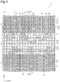
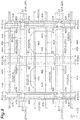
- a storing system 1 includes a traveling rail 2, a plurality of vehicles 3, and a storage unit 4.
- the storing system 1 is installed above a plurality of semiconductor processing devices 10 each including a plurality of device ports 8.
- the storing system 1 temporarily stores front opening unified pods (FOUPs) 9 in each of which a plurality of semiconductor wafers are accommodated. More specifically, in the storing system 1, a FOUP 9 is conveyed between the storage unit 4 and a device port 8 by a vehicle 3 configured to travel on the traveling rail 2, and the FOUP 9 (the FOUP 9 before being fed to the device port 8, or the FOUP 9 after being collected from the device port 8) is temporarily stored in the storage unit 4. To or from the storing system 1, the FOUP 9 is conveyed in or conveyed out by an overhead hoist transfer (OHT) , for example.
- OHT overhead hoist transfer
- Each of the semiconductor processing devices 10 is disposed below the traveling rail 2 in a manner aligned in a plurality of rows (two rows along the first direction D1 in FIG. 1 ).
- the corresponding device ports 8 are disposed so as to face each other between a pair of rows adjacent to each other.
- the traveling rail 2 includes a plurality of first rails 21 and a plurality of second rails 22.
- Each of the first rails 21 extends linearly in the first direction D1, and a predetermined interval is formed between first rails 21 adjacent to each other.
- Each of the second rails 22 extends linearly in a second direction D2 orthogonal to the first direction D1, and a predetermined interval is formed between second rails 22 adjacent to each other.
- the first rails 21 and the second rails 22 are disposed in a grid pattern on the same horizontal plane.
- each of the vehicles 3 includes a traveling unit 31, a transfer unit 32, and a protruding unit 33.
- the traveling unit 31 can travel in the first direction D1 along a pair of first rails 21 adjacent to each other, and also can travel in the second direction D2 along a pair of second rails 22 adjacent to each other.
- the traveling unit 31 includes a body portion 37, four wheels 36, and wheel support arms 38. Each of the wheels 36 is rotatably supported by the corresponding wheel support arm 38 that is provided so as to protrude downward from the body portion 37, and rolls on a tread 24a of the traveling rail 2.
- the transfer unit 32 includes: a holding unit 32a configured to hold a flange portion 9a of a FOUP 9; belts 32b configured to suspend the holding unit 32a; a lifting drive unit 32c configured to raise and lower the holding unit 32a by winding and paying out the belts 32b; and a 0-rotating mechanism 32d configured to rotate the lifting drive unit 32c about the vertical direction (direction orthogonal to both the first direction D1 and the second direction D2).
- a state is illustrated in which the transfer unit 32 is delivering or receiving a FOUP 9 to or from the storage unit 4.
- the protruding unit 33 causes the transfer unit 32 to protrude from the traveling unit 31 in either direction of the first direction D1 and the second direction D2.
- the protrudingunit 33 includes a turningmechanism33a. Abase-endportion of the turning mechanism 33a is rotatably attached to the traveling unit 31, and the transfer unit 32 is attached to a distal-end portion of the turning mechanism 33a.
- a plurality of rectangular (i.e., cell-like) areas are formed.
- Each of the rectangular areas is an area that is surrounded by a pair of first rails 21 adjacent to each other and a pair of second rails 22 adjacent to each other, and is formed in plurality lengthwise and crosswise.
- the expression “lengthwise and crosswise” means being in both the first direction D1 and the second direction D2
- the expression “each of the rectangular areas is formed in plurality lengthwise and crosswise” means that a plurality of the rectangular areas are formed in a matrix pattern so as to be aligned in both the first direction D1 and the second direction D2.
- Each of the rectangular areas forms an opening area having a size that allows a FOUP 9 to pass therethrough in the up-and-down direction.
- the vehicle 3 uses the traveling unit 31 to travel, while using the holding unit 32a of the transfer unit 32 to hold a FOUP 9 above the traveling rail 2.
- the vehicle 3 also uses the transfer unit 32 to deliver and receive a FOUP 9 to and from the storage unit 4 through a predetermined opening area.
- a first opening area (opening area) 2a is an area that is positioned directly above each of the device ports 8.
- a second opening area (opening area) 2b is an area that is positioned directly below a position where the traveling unit 31 stops when the vehicle 3 delivers or receives a FOUP 9 to or from the device port 8 through the first opening area 2a while positioning the transfer unit 32 above the first opening area 2a.
- a third opening area (opening area) 2c is an area other than the first opening area 2a and the second opening area 2b.
- the non-storage area 5 includes areas directly below a plurality of sections each of which is formed by each of the first opening areas 2a and the respective areas that are formed adjacently to the first opening area 2a so as to surround the first opening area 2a, and also includes areas directly below areas of third opening areas 2c that are positioned (interposed) between the respective sections.
- the "areas that are positioned between the respective sections” mean, out of all combinations of two sections among a plurality of the sections, areas obtained by adding all of areas positioned between two sections that constitute at least one combination.
- the non-storage area 5 is an area within which the respective sections are positioned with respect to a line connecting, among outer boundaries of the respective sections, each of outer boundaries that do not face the other sections.
- the storage area 6 is an area other than the non-storage area 5, and the third opening areas 2c are formed directly above the storage area 6.
- the storage area 6 is an area outside of which the respective sections are positioned with respect to the line connecting, among the outer boundaries of the respective sections, each of the outer boundaries that do not face the other sections.
- the storage unit 4 is not provided directly below, among the third opening areas 2c, all of areas that are formed adjacently to the first opening areas 2a so as to surround the first opening areas 2a.
- the storage unit 4 does not have to be provided to the non-storage area 5, and in this case, occurrence of traffic congestion with vehicles 3 can be prevented on the traveling rail 2 near the device ports 8.
- the storage unit 4 is configured with a plurality of rack units 40 adjacent to each other in combination.
- Each of the rack units 40 includes a placement member 51 on which a FOUP 9 is to be placed (described in detail later), and is provided such that the placement member 51 is positioned directly below an area (opening area) surrounded by a pair of first rails 21 adjacent to each other and a pair of second rails 22 adjacent to each other.
- Each of the rack units 40 is attached so as to correspond to a plurality of third opening areas 2c that are formed adjacently to one first rail 21 or one second rail 22 in a manner arranged on both sides of the rail.
- On each of the placement members 51 a plurality of placement portions 50 are formed, each of which is a portion on which a FOUP 9 is to be placed.
- At least one of the rack units 40 is formed such that the placement portions 50 are aligned in a row on the placement member 51, and is provided such that the direction in which the placement portions 50 are aligned in a row is parallel to the first direction D1 or the second direction D2.
- each of the rack units 40 corresponds to the third opening areas 2c that are aligned in a row in either direction of the first direction D1 or the second direction D2.
- a FOUP 9 is delivered or received through each of the corresponding third opening areas 2c.
- each of the rack units 40 corresponds to three third opening areas 2c that are aligned in a row in the second direction D2.
- Each of the first opening areas 2a is formed by partially removing at least one of the corresponding first rails 21 and the corresponding second rails 22.
- Each of the first opening areas 2a has a size corresponding to those of the second opening areas 2b and the third opening areas 2c.
- the first opening areas 2a are areas directly above a plurality of device ports 8 that are aligned in a row in the first direction D1.
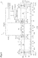
- each of the first rails 21 is formed with an H-shaped steel member having a web portion 23 that is vertically arranged. Upper surfaces of a flange portion 24 formed on the lower end of the web portion 23 are treads 24a for four wheels 36 that the traveling unit 31 of each of the vehicles 3 has.
- Each of the second rails 22 has the same configuration as that of the first rail 21.
- the traveling unit 31 When the traveling unit 31 is positioned directly above a second opening area 2b or a third opening area 2c, the four wheels 36 are positioned at four intersection portions that are formed with a pair of the treads 24a (the treads 24a of the first rails 21) opposed to each other in the second direction D2 and a pair of the treads 24a (the treads 24a of the second rails 22) opposed to each other in the first direction D1.
- the traveling unit 31 changes the direction between the first direction D1 and the second direction D2 by changing the direction of the four wheels 36 simultaneously when the wheels 36 are positioned at the four intersection portions.
- Each of the rack units 40 includes the placement member 51, a plurality of support members 42, and a plurality of reinforcement members 43.
- the placement member 51 is a member on which a FOUP 9 is to be placed.
- the placement member 51 is, for example, a pair of beam-like members 41 provided in a manner spaced apart from each other.
- the pair of beam-like members 41 extends, below a plurality of third opening areas 2c that are aligned in a row in either direction of the first direction D1 or the second direction D2, in the either direction.
- the pair of beam-like members 41 is disposed on the same horizontal plane so as to be parallel to each other. In other words, the pair of beam-like members 41 is horizontally arranged in parallel.
- Each of the support members 42 is a member for supporting the placement member 51.
- the respective support members 42 extend upward from both end portions of each of the pair of beam-like members 41.
- An upper-end portion of each of the support members 42 is attached to the corresponding first rail 21 or the corresponding second rail 22 in a detachable manner.
- each of the support members 42 is suspended from the traveling rail 2 in a detachable manner.
- each of the rack units 40 is suspended below the corresponding third opening areas 2c from the traveling rail 2, and is detachable from the traveling rail 2.
- a pair of beam-like members 41 extends in the second direction D2 below three third opening areas 2c that are aligned in a row in the second direction D2, and the upper-end portion of each of the support members 42 is attached to the corresponding first rail 21 in a detachable manner.
- the reinforcement members 43 each couple together a pair of support members 42 that are connected to end portions of the corresponding pair of beam-like members 41 on the same side, between lower-end portions of the pair of support members 42. With this configuration, change in attitude of each of the support members 42 can be suppressed.
- each of the rack units 40 to the corresponding first rails 21 or the corresponding second rails 22 more specifically.
- a plurality of brackets 25 are fixed with bolts, for example, in a detachable manner.
- the brackets 25 are disposed at pitches corresponding to the third opening areas 2c.
- an upper-end portion of a support member 42 of one rack unit 40 and an upper-end portion of a support member 42 of the other rack unit 40 can be attached with bolts.
- an upper-end portion of a support member 42 of one rack unit 40 and an upper-end portion of a support member 42 of the other rack unit 40 can be attached with bolts.
- each of the rack units 40 can be attached to and detached from the flange portions 24.
- a plurality of FOUPs 9 are placed through the respective third opening areas 2c to which the rack unit 40 corresponds .
- placement member 51 such as the beam-like members 41
- placement portions 50 on each of which a FOUP 9 is to be placed are formed, and upper surfaces of the placement portions 50 are placement surfaces 40a.
- a FOUP 9 placed on each of the placement surfaces 40a is positioned within the corresponding third opening area 2c.
- a plurality of (herein, three) positioning pins (positioning portions) 44 for positioning each of the FOUPs 9 on the rack unit 40 are formed.
- the positioning pins 44 also called kinematic pins, are fitted into recessed portions formed on a bottom surface of the FOUP 9, whereby movement of each of the FOUPs 9 with respect to the rack unit 40 is restricted.
- Each of the rack units 40 is configured such that, when viewed from the horizontal direction, a FOUP 9 placed on a placement surface 40a thereof overlaps the first rails 21 and the second rails 22.
- a space between the placement surface 40a and the first rails 21 and a space between the placement surface 40a and the second rails 22 each have a size that does not allow a FOUP 9 to pass therethrough.
- the rack unit 40 is also configured such that the upper end of each of the FOUPs 9 placed on a placement surface 40a thereof is positioned below the lower end of the body portion 37 included by the traveling unit 31 of each of the vehicles 3 traveling directly above the, FOUP 9. Furthermore, the rack unit 40 is configured such that the upper end of the FOUP 9 placed on the placement surface 40a is positioned above the treads 24a of the traveling rail 2.
- first stopping areas 20a and second stopping areas (adjacent areas) 20b are set.
- the first stopping areas 20a are portions corresponding to a plurality of third opening areas 2c directly above the storage area 6 in the traveling rail 2.
- the second stopping areas 20b are portions corresponding to a plurality of second opening areas 2b each adjacent to the first opening areas 2a in the non-storage area 5 in the traveling rail 2.
- the first stopping areas 20a do not overlap the second stopping areas 20b.
- the storage unit 4 is provided below the first stopping areas 20a, the storage unit 4 is not provided below the second stopping areas 20b. Below the second opening areas 2b (e.g., in areas directly below them), scaffolds 7 for work that are attached to the traveling rail 2 in a suspended manner are provided.
- the first opening areas 2a extend in the first direction D1
- the second stopping areas 20b are portions corresponding to a plurality of second opening areas 2b that are aligned in a row in the first direction D1 on both sides of the first opening areas 2a in the second direction D2.
- Each of the vehicles 3 travels in both directions of the first direction D1 and the second direction D2 with the corresponding transfer unit 32 caused to protrude from the corresponding traveling unit 31 in the first direction D1.
- the traveling unit 31 stops at a first stopping area 20a such that the transfer unit 32 is positioned above the predetermined third opening area 2c with the transfer unit 32 caused to protrude from the traveling unit 31 in the first direction D1.
- the vehicle 3 raises and lowers the holding unit 32a of the transfer unit 32, thereby delivering or receiving the FOUP 9 to or from the predetermined rack unit 40 through the predetermined third opening area 2c.
- the vehicle 3 does not deliver or receive the FOUP 9 to or from the rack unit 40 through the third opening area 2c.
- a position where the traveling unit 31 is stopped when the vehicle 3 delivers or receives the FOUP 9 to or from the rack unit 40 through the third opening area 2c with the transfer unit 32 positioned above the third opening area 2c is set to be a position other than a position directly above the second opening area 2b.
- the vehicle 3 may deliver or receive the FOUP 9 to or from the predetermined rack unit 40 in a manner described below through the predetermined third opening area 2c. Specifically, the vehicle 3 causes the traveling unit 31 to stop at, among a pair of third opening areas 2c adjacent to each other in the storage area 6, a portion corresponding to one third opening area 2c, and positions the transfer unit 32 above the other third opening area 2c. In this state, the vehicle 3 may deliver or receive the FOUP 9 to or from the predetermined rack unit 40 through the other third opening area 2c.
- the vehicle 3 does not deliver or receive the FOUP 9 to or from the rack unit 40 through a first opening area 2a or a second opening area 2b.
- the traveling unit 31 stops at a portion corresponding to a second stopping area 20b such that the transfer unit 32 is positioned above the first opening area 2a directly above the device port 8 with the transfer unit 32 caused to protrude from the traveling unit 31 in the second direction D2.
- the vehicle 3 raises and lowers the holding unit 32a of the transfer unit 32, thereby delivering or receiving the FOUP 9 to or from the device port 8 through the first opening area 2a.
- the traveling unit 31 may stop at the portion displaced from the portion corresponding to the grid in the second opening area 2b (i.e., the traveling unit 31 may stop at the portion extending across the respective portions corresponding to two grids adjacent to each other), and in this state, the vehicle 3 may deliver or receive the FOUP 9 to or from the device port 8.
- each of the rack units 40 constituting the storage unit 4 is provided such that the corresponding beam-like members 41 as the placement member 51 on each of which a FOUP 9 is to be placed are positioned directly below the corresponding third opening areas 2c.
- This enables a plurality of the rack units 40 to be combined appropriately to constitute the storage unit 4 having a desired shape.
- flexibility in installation of the storage unit 4 can be improved.
- each of the rack units includes the support members 42 supporting the corresponding placement member 51, and the support members 42 are suspended from the traveling rail 2 in a detachable manner.
- the placement member 51 can be easily disposed at a suitable height.
- At least one of the rack units 40 is formed such that a plurality of placement portions 50, on each of which a FOUP 9 is to be placed, are aligned in a row in the corresponding placement member 51, and is also provided such that a direction in which the placement portions 50 are aligned in a row is parallel to the first direction D1 or the second direction D2.
- all of the respective rack units 40 are configured so as to correspond to a plurality of third opening areas 2c that are arranged in a matrix pattern (i.e., arranged so as to be aligned in a plurality of rows in both directions of the first direction D1 and the second direction D2)
- flexibility in installation of the storage unit 4 can be prevented from decreasing. This is particularly advantageous, for example, when a rack unit 40 for only one row of the third opening areas 2c is desired to be removed.
- each of the areas surrounded by a pair of first rails 21 adjacent to each other and a pair of second rails 22 adjacent to each other forms an opening area having a size that allows a FOUP 9 to pass therethrough in the up-and-down direction, and each of the vehicles 3 travels while holding the FOUP 9 above the traveling rail 2 to deliver and receive the FOUP 9 to and from the placement member 51 through the third opening area 2c.
- a function and an effect of improving flexibility in installation of the storage unit 4 can be satisfactorily obtained.
- each of the placement members 51 is a pair of beam-like members 41 provided in a manner spaced apart from each other. This allows a FOUP 9 to be placed on the pair of beam-like members 41, and thus air currents can be prevented from being hindered by the rack units 40 in comparison with the case in which the FOUP 9 is to be placed on a plate-like member, for example. Particularly when this storing system 1 is used in a clean room, air currents in up-and-down directions for keeping inside of the clean room in a clean state can be prevented from being hindered.
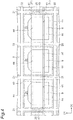
- the traveling rail 2A includes a plurality of first rail members 61, a plurality of second rail members 62, and a plurality of intersection rail members 63.
- Each of the first rail members 61 extends linearly in the first direction D1.
- the respective first rail members 61 form a plurality of rows disposed in plurality at predetermined intervals along the first direction D1.
- the respective rows of these first rail members 61 are aligned in the second direction D2.
- Each of the second rail members 62 extends linearly in the second direction D2.
- the respective second rail members 62 form a plurality of rows disposed in plurality at predetermined intervals along the second direction D2.
- the respective rows of these second rail members 62 are aligned in the first direction D1.
- the space between first rail members 61 adjacent to each other in a row of the first rail members 61 and the space between second rail members 62 adjacent to each other in a row of the second rail members 62 are the same.
- Each of the intersection rail members 63 is disposed in a space between first rail members 61 adjacent to each other in a row of the first rail members 61 (i.e., a space between second rail members 62 adjacent to each other in a row of the second rail members 62).
- first direction D1 between each of the intersection rail members 63 and end portions of the-respective first rail members 61 on both sides of the intersection rail member 63, slits (gaps) S1 are formed.
- slits (gaps) S2 are formed in the second direction D2.
- the slits S1 and S2 are formed so as to have a width sufficiently smaller than the diameter of each of the wheels 36 of the vehicles 3A.
- the first rail members 61, the second rail members 62, and the intersection rail members 63 are each suspended from a ceiling, for example.
- the first rail members 61 and the intersection rail members 63 disposed along the first direction D1 constitute first rails 21A.
- the second rail members 62 and the intersection rail members 63 disposed along the second direction D2 constitute second rails 22A.
- the intersection rail members 63 serve both as the first rails 21A and the second rails 22A to constitute intersection portions of the first rails 21A and the second rails 22A.
- the traveling rail 2A forms lengthwise and crosswise a plurality of areas each of which is surrounded by a pair of first rails 21A adjacent to each other and a pair of second rails 22A adjacent to each other.
- Each of the vehicles 3A includes a traveling unit 31A and a transfer unit 32.
- the traveling unit 31A includes a body portion 37A, four wheels 36A, and wheel support arms 38A.
- Each of the wheels 36A is rotatably supported by the corresponding wheel support arm 38A that is provided so as to protrude upward from the body portion 37A, and rolls on a tread 24a of the traveling rail 2A.
- the body portion 37A and the transfer unit 32 are suspended below the traveling rail 2A from the respective wheels 36A that are positioned above the traveling rail 2A, with the corresponding wheel support arms 38A interposed therebetween.
- the transfer unit 32 herein is configured in the same manner as the transfer unit 32 that each of the vehicles 3 of the first embodiment has, and thus description thereof is omitted.
- Each of the rack units 40A includes a placement member 51A, two pairs of support members 42A, and two connection members 43A connecting lower-end portions of the respective pair of support members 42A.
- Each of the rack units 40A illustrated in FIG. 6 and FIG. 7 is configured to correspond to one area that is surrounded by a pair of first rails 21A adjacent to each other and a pair of second rails 22A adjacent to each other.
- the placement member 51A is provided at a height that, in a state in which a FOUP 9 is placed on the upper surface thereof, allows each of the vehicles 3A to travel above the FOUP 9 without coming into contact with the FOUP 9.
- the placement member 51A is a pair of beam-like members 41A that are laid between the two connection members 43A. On upper surfaces of placement portions 50A of the beam-like members 41A, a plurality of (herein, three) positioning pins 44A are formed.
- Each of the support members 42A is suspended from the corresponding intersection rail member 63 in a detachable manner.
- the support member 42A is provided four, for example, for one intersection rail member 63, and the respective support members 42A support placement members 51A of the respective rack units 40A that are provided to four corners of the intersection rail member 63.
- a bracket 65 is provided on the lower side of each of the intersection rail members 63.
- through holes are formed at positions corresponding to the upper-end portions of the respective support members 42A.
- a threaded hole is formed in the axial direction.
- each of the rack units 40A that is detachable from the traveling rail 2A is not limited to the example described above.
- the rack unit 40A may be attached to the traveling rail 2A with a simple configuration in which locked portions are provided to each of the brackets 65, and locking portions are provided to the upper-end portions of the corresponding support members 42A, and the respective support members 42A are locked to the bracket 65.
- locked portions may be provided to the intersection rail member 63, and the respective support members 42A may be directly locked to the intersection rail member 63.
- a plurality of support members 42A provided to the same intersection rail member 63 may be shared by a plurality of rack units 40A.
- each of the rack units 40A may be configured to correspond to an area in which a plurality of areas, each of which is surrounded by a pair of first rails 21A adjacent to each other and a pair of second rails 22A adjacent to each other, are aligned.
- the rack unit 40A may be configured to correspond to the areas that are aligned in a row in either direction of the first direction D1 or the second direction D2.
- each of the rack units 40A illustrated in FIG. 8 and FIG. 9 is configured to correspond to the two areas that are aligned in a row in the second direction D2.
- the vehicle 3A uses the traveling unit 31A to travel and cause a FOUP 9 to pass between a plurality of support members 42A while using the transfer unit 32 to hold the FOUP 9 below the traveling rail 2A.
- the slits S1 and S2 are formed so as to have a width sufficiently smaller than the diameter of each of the wheels 36A of the vehicle 3A, each of the wheels 36A can pass over the slits S1 when the vehicle 3A travels in the first direction D1, and each of the wheels 36A can pass over the slits S2 when the vehicle 3A travels in the second direction D2.
- the wheel support arm 38A supporting the wheel 36A passes through the slits S2.
- the wheel support arm 38A supporting the wheel 36A passes through the slits S1.
- the vehicle 3A can travel along the traveling rail 2A without coming into contact with the traveling rail 2A.
- each of the support members 42A is suspended from the corresponding intersection rail member 63 and the vehicle 3A does not travel directly below the intersection rail member 63, the vehicle 3A does not come into contact with the support member 42A. Thus, the vehicle 3A can travel along the traveling rail 2A without coming into contact with a rack unit 40A.
- the vehicle 3A delivers and receives a FOUP 9 to and from the rack unit 40A without causing the FOUP 9 to pass through an area that is surrounded by a pair of first rails 21A adjacent to each other and a pair of second rails 22A adjacent to each other.
- each of the support members 42A is suspended from the corresponding intersection rail member 63 that is an intersection portion of the corresponding first rail 21A and the corresponding second rail 22A.
- Each of the vehicles 3A travels to cause a FOUP 9 to pass between the support members 42A while holding the FOUP 9 below the traveling rail 2A.
- a function and an effect of improving flexibility in installation of the storage unit 4 can be satisfactorily obtained.
- the traveling rail 2A can be installed at a position closer to the ceiling of the semiconductor manufacturing plant than in the storing system 1 according to the first embodiment.
- the traveling rail 2A can be installed at a position higher than the traveling rail 2 of the first embodiment.
- a semiconductor processing device 10 that is relatively tall e.g., a semiconductor processing device 10 that is taller than a height where the traveling rail 2 of the first embodiment is installed
- the FOUP 9 in order for each of the vehicles 3 to deliver or receive a FOUP 9 to or from a device port 8 below the traveling rail 2, the FOUP 9 needs to be caused to pass through a first opening area 2a formed in the traveling rail 2.
- the position of the first opening area 2a in the traveling rail 2 must be matched to the layout of the device port 8 below the traveling rail 2.
- the traveling rail 2A in the storing system 1A according to the second embodiment, there is not such a restriction, and thus the traveling rail 2A can be installed flexibly regardless of the layout of the device port 8 disposed below the traveling rail 2A. In other words, flexibility in layout of device ports 8 disposed below the traveling rail 2A can be improved.
- each of the rack units 40 only has to be configured to correspond to at least one third opening area 2c, and each of all rack units 40 may be configured to correspond to one third opening area 2c.
- only one placement portion 50 that is a portion on which a FOUP 9 is to be placed may be formed on each of the placement members 51.
- any rack units 40 do not have to be configured to correspond to a plurality of third opening areas 2c that are aligned in a row in the first direction D1 or the second direction D2.
- each of all rack units 40 configured to correspond to these third opening areas 2c may be configured to correspond to a plurality of first opening areas 2a that are arranged in a matrix pattern of m ⁇ n (m and n are integers of two or larger) in the first direction D1 and the second direction D2.
- the one traveling rail 2 herein means a traveling rail 2 that forms a range in which each of the vehicles 3 can use the corresponding traveling unit 31 to travel by itself.
- first rails 21 and 21A and the second rails 22 and 22A may be disposed, not only on the same horizontal plane, but also on the same inclined plane, for example .
- the storing systems 1 and 1A do not have to include a plurality of vehicles 3 and 3A, respectively, and each may include only one.
- the protruding unit 33 of each of the vehicles 3 may be a unit configured to cause the corresponding transfer unit 32 from the corresponding traveling unit 31 to protrude in either direction of the first direction D1 or the second direction D2.
- the protruding unit 33 may be a unit configured to cause the transfer unit 32 to protrude from the traveling unit 31 in at least one direction of the first direction D1 and the second direction D2.
- the protruding unit 33 may include a slide mechanism configured to move the transfer unit 32 forward and backward, and may use this slide mechanism to cause the transfer unit 32 to protrude from the traveling unit 31 in either direction of the first direction D1 or the second direction D2.
- the protruding unit 33 may include a swing mechanism configured to rotate an arm extending horizontally from the traveling unit 31 about the central axis on the traveling unit 31 thereby turning the transfer unit 32 held on the distal end side of the arm, and may use this swing mechanism to cause the transfer unit 32 to protrude from the traveling unit 31 in either direction of the first direction D1 or the second direction D2.
- the protruding unit 33 also may leave the transfer unit 32 to continuously protrude from the traveling unit 31 in either direction of the first direction D1 or the second direction D2.
- the rack units 40 and 40A may be providedbelow second stopping areas 20b.
- the vehicles 3 and 3A do not deliver or receive a FOUP 9 to or from the rack units 40 and 40A in a state in which the traveling units 31 and 31A stop at portions corresponding to the second stopping area 20b, respectively.
- a plurality of (two, for example) rack units 40 and 40A provided adjacently to each other may share support members 42 and 42A on the side adjacent to each other, respectively.
- one (single) support member 42A may be suspended from each of the intersection rail members 63, and this support member 42A may be shared by a plurality of rack units 40A.
- Articles stored by the storing system according to one aspect of the present invention are not limited to FOUPs 9 in each of which a plurality of semiconductor wafers are accommodated, and may be other containers in each of which glass wafers, reticles, or the like are accommodated.
- the storing system according to one aspect of the present invention can be used not only in the semiconductor manufacturing plant, but also in other facilities.
- a storing system that enables flexibility in installation of a storage unit to be improved can be provided.
- 1, 1A... storing system 2, 2A... traveling rail, 2a... first opening area (area, opening area), 2b... second opening area (area, opening area), 2c... third opening area (area, opening area), 3, 3A... vehicle, 4... storage unit, 9... FOUP (article), 21, 21A... first rail, 22, 22A... second rail, 31, 31A... traveling unit, 32... transfer unit, 40, 40A... rack unit, 41, 41A... beam-like member, 42, 42A... support member, 50, 50A... placement portion, 51, 51A... placement member, D1... first direction, D2... second direction
Landscapes
- Engineering & Computer Science (AREA)
- Physics & Mathematics (AREA)
- Condensed Matter Physics & Semiconductors (AREA)
- General Physics & Mathematics (AREA)
- Manufacturing & Machinery (AREA)
- Computer Hardware Design (AREA)
- Microelectronics & Electronic Packaging (AREA)
- Power Engineering (AREA)
- Mechanical Engineering (AREA)
- Container, Conveyance, Adherence, Positioning, Of Wafer (AREA)
- Warehouses Or Storage Devices (AREA)
Claims (6)
- Ein Lagersystem (1, 1A), das folgende Merkmale aufweist:eine Bewegungsschiene (2, 2A), die eine Mehrzahl erster Schienen (21, 21A), die sich in einer ersten Richtung erstrecken, und eine Mehrzahl zweiter Schienen (22, 22A) aufweist, die sich in einer zweiten Richtung orthogonal zu der ersten Richtung erstrecken, wobei die ersten Schienen (21, 21A) und die zweiten Schienen (22, 22A) in einer Gitterstruktur auf der gleichen Ebene angeordnet sind und dabei der Länge nach und quer eine Mehrzahl von Bereichen ausbilden, die jeweils durch ein Paar der ersten Schienen (21, 21A), die zueinander benachbart sind, und ein Paar der zweiten Schienen (22, 22A), die zueinander benachbart sind, umgeben sind;ein Fahrzeug (3, 3A), das eine Bewegungseinheit (31, 31A), die dazu ausgebildet ist, sich auf der Bewegungsschiene (2, 2A) in beiden Richtungen der ersten Richtung und der zweiten Richtung zu bewegen, und eine Übertragungseinheit (32) aufweist, die dazu ausgebildet ist, einen Gegenstand (9) zu halten, um den Gegenstand (9) anzuheben und abzusenken; undeine Lagereinheit (4), die unterhalb der Bewegungsschiene (2, 2A) vorgesehen ist, auf der der Gegenstand (9) platziert werden soll, wobeidie Bewegungsschiene (2, 2A) ferner eine Mehrzahl sich schneidender Schienenbauteile (63) aufweist, die sich schneidende Abschnitte der ersten Schienen (21, 21A) und der zweiten Schienen (22, 22A) ausbilden,das Fahrzeug (3, 3A) dazu ausgebildet ist, den Gegenstand (9) an die Lagereinheit (4) zu liefern und denselben von der Lagereinheit (4) aufzunehmen,die Lagereinheit (4) eine Mehrzahl von Gestelleinheiten (40, 40A) aufweist, die benachbart zueinander sind,jede der Gestelleinheiten (40, 40A) ein Platzierungsbauteil (51, 51A) aufweist, auf dem der Gegenstand (9) platziert werden soll, derart vorgesehen ist, dass das Platzierungsbauteil (51, 51A) direkt unterhalb des entsprechenden Bereichs positioniert ist, und von der Bewegungsschiene (2, 2A) lösbar ist,das Lagersystem (1, 1A) ferner eine Mehrzahl von Halterungen (25, 65) aufweist, die jeweils an den sich schneidenden Schienenbauteilen (63) vorgesehen sind,jede der Halterungen (25, 65) es ermöglicht, dass die vier Gestelleinheiten (40, 40A), die an vier Ecken des entsprechenden sich schneidenden Schienenbauteils (63) angeordnet sind, lösbar sind, undjede der Gestelleinheiten (40, 40A) von der Bewegungsschiene (2, 2A) durch die vier Halterungen (25, 65) lösbar ist, die jeweils an vier Ecken der Gestelleinheit (40, 40A) positioniert sind.
- Das Lagersystem (1, 1A) gemäß Anspruch 1, bei dem jede der Gestelleinheiten (40, 40A) ein Trägerbauteil (42) aufweist, das in lösbarer Weise von der Bewegungsschiene (2, 2A) aufgehängt ist und das entsprechende Platzierungsbauteil (51, 51A) trägt.
- Das Lagersystem (1, 1A) gemäß Anspruch 2, bei dem zumindest eine der Gestelleinheiten (40, 40A) derart gebildet ist, dass eine Mehrzahl von Platzierungsabschnitten (50, 50A), auf denen jeweils der Gegenstand (9) platziert werden soll, in einer Reihe in dem entsprechenden Platzierungsbauteil (51, 51A) ausgerichtet ist, und außerdem derart vorgesehen ist, dass eine Richtung, in der die Platzierungsabschnitte (50, 50A) in einer Reihe ausgerichtet sind, parallel zu der ersten Richtung oder der zweiten Richtung ist.
- Das Lagersystem (1, 1A) gemäß einem der Ansprüche 1 bis 3, bei demjeder der Bereiche einen Öffnungsbereich (2a, 2b, 2c) mit einer Größe bildet, die es ermöglicht, dass der Gegenstand (9) in einer Auf-und-Ab-Richtung durch den Öffnungsbereich (2a, 2b, 2c) laufen kann, unddas Fahrzeug (3, 3A) zu Folgendem ausgebildet ist:Bewegen, während es den Gegenstand (9) oberhalb der Bewegungsschiene (2, 2A) hält, undLiefern des Gegenstands (9) an und Aufnehmen desselben von dem Platzierungsbauteil (51, 51A) durch den Öffnungsbereich (2a, 2b, 2c).
- Das Lagersystem (1, 1A) gemäß Anspruch 2 oder 3, bei demjedes der Trägerbauteile (42) von einem sich schneidenden Abschnitt der entsprechenden ersten Schiene (21, 21A) und der entsprechenden zweiten Schiene (22, 22A) aufgehängt ist unddas Fahrzeug (3, 3A) dazu ausgebildet ist, sich zu bewegen und dabei zu bewirken, dass der Gegenstand (9) zwischen den Trägerbauteilen (42) läuft, während der Gegenstand (9) unterhalb der Bewegungsschiene (2, 2A) gehalten wird.
- Das Lagersystem (1, 1A) gemäß einem der Ansprüche 1 bis 5, bei dem jedes der Platzierungsbauteile (51, 51A) ein Paar balkenartiger Bauteile (41) ist, die in einer voneinander beabstandeten Weise vorgesehen sind.
Applications Claiming Priority (2)
| Application Number | Priority Date | Filing Date | Title |
|---|---|---|---|
| JP2017100262 | 2017-05-19 | ||
| PCT/JP2018/015894 WO2018211898A1 (ja) | 2017-05-19 | 2018-04-17 | 保管システム |
Publications (3)
| Publication Number | Publication Date |
|---|---|
| EP3637459A1 EP3637459A1 (de) | 2020-04-15 |
| EP3637459A4 EP3637459A4 (de) | 2021-01-20 |
| EP3637459B1 true EP3637459B1 (de) | 2021-12-22 |
Family
ID=64273552
Family Applications (1)
| Application Number | Title | Priority Date | Filing Date |
|---|---|---|---|
| EP18801638.0A Active EP3637459B1 (de) | 2017-05-19 | 2018-04-17 | Aufbewahrungssystem |
Country Status (8)
| Country | Link |
|---|---|
| US (1) | US11171027B2 (de) |
| EP (1) | EP3637459B1 (de) |
| JP (1) | JP6705556B2 (de) |
| KR (1) | KR102302099B1 (de) |
| CN (1) | CN110603632B (de) |
| IL (1) | IL270597B (de) |
| TW (1) | TWI734915B (de) |
| WO (1) | WO2018211898A1 (de) |
Families Citing this family (2)
| Publication number | Priority date | Publication date | Assignee | Title |
|---|---|---|---|---|
| KR102701743B1 (ko) * | 2019-09-18 | 2024-08-30 | 무라다기카이가부시끼가이샤 | 반송 시스템 및 보관부 |
| WO2021090543A1 (ja) * | 2019-11-07 | 2021-05-14 | 村田機械株式会社 | 搬送システム及びグリッドシステム |
Family Cites Families (17)
| Publication number | Priority date | Publication date | Assignee | Title |
|---|---|---|---|---|
| US4088232A (en) * | 1974-04-01 | 1978-05-09 | Clark Equipment Co. | Apparatus with storage cells disposed adjacent vertical shafts having covers and a lift means movable thereabove |
| JP3067656B2 (ja) * | 1996-09-30 | 2000-07-17 | 村田機械株式会社 | ワーク搬送システム |
| TW200630284A (en) * | 2005-02-25 | 2006-09-01 | Murata Machinery Ltd | A storage management system |
| JP4858018B2 (ja) * | 2006-09-01 | 2012-01-18 | ムラテックオートメーション株式会社 | 被搬送物保管システム |
| US7850412B2 (en) | 2006-09-25 | 2010-12-14 | Bec Companies, Inc. | Overhead boat storage system |
| JP5162899B2 (ja) | 2006-12-28 | 2013-03-13 | 村田機械株式会社 | 被搬送物の保管装置 |
| JP5239192B2 (ja) * | 2007-03-30 | 2013-07-17 | 村田機械株式会社 | 保管装置 |
| JP5163866B2 (ja) * | 2007-12-10 | 2013-03-13 | 村田機械株式会社 | 天井バッファとその移設方法 |
| US8483866B2 (en) * | 2009-04-30 | 2013-07-09 | Taiwan Semiconductor Manufacturing Co., Ltd. | Automated materials handling system having multiple categories of overhead buffers |
| JP5429570B2 (ja) * | 2010-03-08 | 2014-02-26 | 株式会社ダイフク | 物品搬送設備 |
| JP5729415B2 (ja) * | 2010-11-04 | 2015-06-03 | 村田機械株式会社 | 搬送システム及び搬送方法 |
| JP5229363B2 (ja) * | 2010-11-04 | 2013-07-03 | 村田機械株式会社 | 搬送システム及び搬送方法 |
| US9385019B2 (en) | 2012-06-21 | 2016-07-05 | Globalfoundries Inc. | Overhead substrate handling and storage system |
| GB201404870D0 (en) * | 2014-03-18 | 2014-04-30 | Ocado Ltd | Robotic service device and handling method |
| JP2015174181A (ja) | 2014-03-14 | 2015-10-05 | 牧野フライス精機株式会社 | 工作機械の固定部材 |
| US9415934B2 (en) | 2014-05-14 | 2016-08-16 | Murata Machinery, Ltd. | Transport system and transport method |
| CN106573728B (zh) * | 2014-09-10 | 2019-09-24 | 村田机械株式会社 | 临时保管系统、使用了它的输送系统和临时保管方法 |
-
2018
- 2018-04-17 WO PCT/JP2018/015894 patent/WO2018211898A1/ja active Application Filing
- 2018-04-17 CN CN201880029757.XA patent/CN110603632B/zh active Active
- 2018-04-17 US US16/612,924 patent/US11171027B2/en active Active
- 2018-04-17 KR KR1020197032416A patent/KR102302099B1/ko active IP Right Grant
- 2018-04-17 EP EP18801638.0A patent/EP3637459B1/de active Active
- 2018-04-17 JP JP2019519139A patent/JP6705556B2/ja active Active
- 2018-05-14 TW TW107116305A patent/TWI734915B/zh active
-
2019
- 2019-11-12 IL IL270597A patent/IL270597B/en unknown
Also Published As
| Publication number | Publication date |
|---|---|
| KR20190137124A (ko) | 2019-12-10 |
| TW201900532A (zh) | 2019-01-01 |
| KR102302099B1 (ko) | 2021-09-13 |
| CN110603632B (zh) | 2023-03-14 |
| EP3637459A4 (de) | 2021-01-20 |
| IL270597B (en) | 2022-06-01 |
| JPWO2018211898A1 (ja) | 2020-01-16 |
| US20200203203A1 (en) | 2020-06-25 |
| CN110603632A (zh) | 2019-12-20 |
| US11171027B2 (en) | 2021-11-09 |
| JP6705556B2 (ja) | 2020-06-03 |
| TWI734915B (zh) | 2021-08-01 |
| WO2018211898A1 (ja) | 2018-11-22 |
| EP3637459A1 (de) | 2020-04-15 |
Similar Documents
| Publication | Publication Date | Title |
|---|---|---|
| US11276596B2 (en) | Conveyance system | |
| EP3637459B1 (de) | Aufbewahrungssystem | |
| US20080022881A1 (en) | Traveling rails for carriage | |
| EP3770082B1 (de) | Stockersystem | |
| EP3647230B1 (de) | Fördersystem und förderverfahren | |
| EP4032774A1 (de) | Fördersystem und speichereinheit | |
| JP7235059B2 (ja) | 保管システム | |
| JP2018177376A (ja) | 搬送システム及び搬送方法 | |
| JP2018193222A (ja) | 保管システム | |
| WO2003088350A1 (fr) | Systeme de convoyage de contenants fermes | |
| JP2018193223A (ja) | 保管システム及び保管方法 | |
| KR20210126108A (ko) | 반송차 시스템 | |
| EP4276040A1 (de) | Deckenablagesystem | |
| EP4245695A1 (de) | Transportsystem | |
| CN116605602A (zh) | 保管架及搬送车系统 | |
| TW202402640A (zh) | 搬送系統 |
Legal Events
| Date | Code | Title | Description |
|---|---|---|---|
| STAA | Information on the status of an ep patent application or granted ep patent |
Free format text: STATUS: THE INTERNATIONAL PUBLICATION HAS BEEN MADE |
|
| PUAI | Public reference made under article 153(3) epc to a published international application that has entered the european phase |
Free format text: ORIGINAL CODE: 0009012 |
|
| STAA | Information on the status of an ep patent application or granted ep patent |
Free format text: STATUS: REQUEST FOR EXAMINATION WAS MADE |
|
| 17P | Request for examination filed |
Effective date: 20191204 |
|
| AK | Designated contracting states |
Kind code of ref document: A1 Designated state(s): AL AT BE BG CH CY CZ DE DK EE ES FI FR GB GR HR HU IE IS IT LI LT LU LV MC MK MT NL NO PL PT RO RS SE SI SK SM TR |
|
| AX | Request for extension of the european patent |
Extension state: BA ME |
|
| DAV | Request for validation of the european patent (deleted) | ||
| DAX | Request for extension of the european patent (deleted) | ||
| A4 | Supplementary search report drawn up and despatched |
Effective date: 20201223 |
|
| RIC1 | Information provided on ipc code assigned before grant |
Ipc: H01L 21/677 20060101AFI20201217BHEP Ipc: B65G 1/04 20060101ALI20201217BHEP |
|
| GRAP | Despatch of communication of intention to grant a patent |
Free format text: ORIGINAL CODE: EPIDOSNIGR1 |
|
| STAA | Information on the status of an ep patent application or granted ep patent |
Free format text: STATUS: GRANT OF PATENT IS INTENDED |
|
| INTG | Intention to grant announced |
Effective date: 20210709 |
|
| GRAS | Grant fee paid |
Free format text: ORIGINAL CODE: EPIDOSNIGR3 |
|
| GRAA | (expected) grant |
Free format text: ORIGINAL CODE: 0009210 |
|
| STAA | Information on the status of an ep patent application or granted ep patent |
Free format text: STATUS: THE PATENT HAS BEEN GRANTED |
|
| AK | Designated contracting states |
Kind code of ref document: B1 Designated state(s): AL AT BE BG CH CY CZ DE DK EE ES FI FR GB GR HR HU IE IS IT LI LT LU LV MC MK MT NL NO PL PT RO RS SE SI SK SM TR |
|
| REG | Reference to a national code |
Ref country code: GB Ref legal event code: FG4D |
|
| REG | Reference to a national code |
Ref country code: CH Ref legal event code: EP |
|
| REG | Reference to a national code |
Ref country code: DE Ref legal event code: R096 Ref document number: 602018028602 Country of ref document: DE |
|
| REG | Reference to a national code |
Ref country code: AT Ref legal event code: REF Ref document number: 1457626 Country of ref document: AT Kind code of ref document: T Effective date: 20220115 |
|
| REG | Reference to a national code |
Ref country code: IE Ref legal event code: FG4D |
|
| REG | Reference to a national code |
Ref country code: LT Ref legal event code: MG9D |
|
| PG25 | Lapsed in a contracting state [announced via postgrant information from national office to epo] |
Ref country code: RS Free format text: LAPSE BECAUSE OF FAILURE TO SUBMIT A TRANSLATION OF THE DESCRIPTION OR TO PAY THE FEE WITHIN THE PRESCRIBED TIME-LIMIT Effective date: 20211222 Ref country code: LT Free format text: LAPSE BECAUSE OF FAILURE TO SUBMIT A TRANSLATION OF THE DESCRIPTION OR TO PAY THE FEE WITHIN THE PRESCRIBED TIME-LIMIT Effective date: 20211222 Ref country code: FI Free format text: LAPSE BECAUSE OF FAILURE TO SUBMIT A TRANSLATION OF THE DESCRIPTION OR TO PAY THE FEE WITHIN THE PRESCRIBED TIME-LIMIT Effective date: 20211222 Ref country code: BG Free format text: LAPSE BECAUSE OF FAILURE TO SUBMIT A TRANSLATION OF THE DESCRIPTION OR TO PAY THE FEE WITHIN THE PRESCRIBED TIME-LIMIT Effective date: 20220322 |
|
| REG | Reference to a national code |
Ref country code: NL Ref legal event code: MP Effective date: 20211222 |
|
| REG | Reference to a national code |
Ref country code: AT Ref legal event code: MK05 Ref document number: 1457626 Country of ref document: AT Kind code of ref document: T Effective date: 20211222 |
|
| PG25 | Lapsed in a contracting state [announced via postgrant information from national office to epo] |
Ref country code: SE Free format text: LAPSE BECAUSE OF FAILURE TO SUBMIT A TRANSLATION OF THE DESCRIPTION OR TO PAY THE FEE WITHIN THE PRESCRIBED TIME-LIMIT Effective date: 20211222 Ref country code: NO Free format text: LAPSE BECAUSE OF FAILURE TO SUBMIT A TRANSLATION OF THE DESCRIPTION OR TO PAY THE FEE WITHIN THE PRESCRIBED TIME-LIMIT Effective date: 20220322 Ref country code: LV Free format text: LAPSE BECAUSE OF FAILURE TO SUBMIT A TRANSLATION OF THE DESCRIPTION OR TO PAY THE FEE WITHIN THE PRESCRIBED TIME-LIMIT Effective date: 20211222 Ref country code: HR Free format text: LAPSE BECAUSE OF FAILURE TO SUBMIT A TRANSLATION OF THE DESCRIPTION OR TO PAY THE FEE WITHIN THE PRESCRIBED TIME-LIMIT Effective date: 20211222 Ref country code: GR Free format text: LAPSE BECAUSE OF FAILURE TO SUBMIT A TRANSLATION OF THE DESCRIPTION OR TO PAY THE FEE WITHIN THE PRESCRIBED TIME-LIMIT Effective date: 20220323 |
|
| PG25 | Lapsed in a contracting state [announced via postgrant information from national office to epo] |
Ref country code: NL Free format text: LAPSE BECAUSE OF FAILURE TO SUBMIT A TRANSLATION OF THE DESCRIPTION OR TO PAY THE FEE WITHIN THE PRESCRIBED TIME-LIMIT Effective date: 20211222 |
|
| PG25 | Lapsed in a contracting state [announced via postgrant information from national office to epo] |
Ref country code: SM Free format text: LAPSE BECAUSE OF FAILURE TO SUBMIT A TRANSLATION OF THE DESCRIPTION OR TO PAY THE FEE WITHIN THE PRESCRIBED TIME-LIMIT Effective date: 20211222 Ref country code: SK Free format text: LAPSE BECAUSE OF FAILURE TO SUBMIT A TRANSLATION OF THE DESCRIPTION OR TO PAY THE FEE WITHIN THE PRESCRIBED TIME-LIMIT Effective date: 20211222 Ref country code: RO Free format text: LAPSE BECAUSE OF FAILURE TO SUBMIT A TRANSLATION OF THE DESCRIPTION OR TO PAY THE FEE WITHIN THE PRESCRIBED TIME-LIMIT Effective date: 20211222 Ref country code: PT Free format text: LAPSE BECAUSE OF FAILURE TO SUBMIT A TRANSLATION OF THE DESCRIPTION OR TO PAY THE FEE WITHIN THE PRESCRIBED TIME-LIMIT Effective date: 20220422 Ref country code: ES Free format text: LAPSE BECAUSE OF FAILURE TO SUBMIT A TRANSLATION OF THE DESCRIPTION OR TO PAY THE FEE WITHIN THE PRESCRIBED TIME-LIMIT Effective date: 20211222 Ref country code: EE Free format text: LAPSE BECAUSE OF FAILURE TO SUBMIT A TRANSLATION OF THE DESCRIPTION OR TO PAY THE FEE WITHIN THE PRESCRIBED TIME-LIMIT Effective date: 20211222 Ref country code: CZ Free format text: LAPSE BECAUSE OF FAILURE TO SUBMIT A TRANSLATION OF THE DESCRIPTION OR TO PAY THE FEE WITHIN THE PRESCRIBED TIME-LIMIT Effective date: 20211222 |
|
| PG25 | Lapsed in a contracting state [announced via postgrant information from national office to epo] |
Ref country code: PL Free format text: LAPSE BECAUSE OF FAILURE TO SUBMIT A TRANSLATION OF THE DESCRIPTION OR TO PAY THE FEE WITHIN THE PRESCRIBED TIME-LIMIT Effective date: 20211222 Ref country code: AT Free format text: LAPSE BECAUSE OF FAILURE TO SUBMIT A TRANSLATION OF THE DESCRIPTION OR TO PAY THE FEE WITHIN THE PRESCRIBED TIME-LIMIT Effective date: 20211222 |
|
| REG | Reference to a national code |
Ref country code: DE Ref legal event code: R097 Ref document number: 602018028602 Country of ref document: DE |
|
| PG25 | Lapsed in a contracting state [announced via postgrant information from national office to epo] |
Ref country code: IS Free format text: LAPSE BECAUSE OF FAILURE TO SUBMIT A TRANSLATION OF THE DESCRIPTION OR TO PAY THE FEE WITHIN THE PRESCRIBED TIME-LIMIT Effective date: 20220422 |
|
| PLBE | No opposition filed within time limit |
Free format text: ORIGINAL CODE: 0009261 |
|
| STAA | Information on the status of an ep patent application or granted ep patent |
Free format text: STATUS: NO OPPOSITION FILED WITHIN TIME LIMIT |
|
| PG25 | Lapsed in a contracting state [announced via postgrant information from national office to epo] |
Ref country code: DK Free format text: LAPSE BECAUSE OF FAILURE TO SUBMIT A TRANSLATION OF THE DESCRIPTION OR TO PAY THE FEE WITHIN THE PRESCRIBED TIME-LIMIT Effective date: 20211222 Ref country code: AL Free format text: LAPSE BECAUSE OF FAILURE TO SUBMIT A TRANSLATION OF THE DESCRIPTION OR TO PAY THE FEE WITHIN THE PRESCRIBED TIME-LIMIT Effective date: 20211222 |
|
| 26N | No opposition filed |
Effective date: 20220923 |
|
| REG | Reference to a national code |
Ref country code: CH Ref legal event code: PL |
|
| GBPC | Gb: european patent ceased through non-payment of renewal fee |
Effective date: 20220417 |
|
| REG | Reference to a national code |
Ref country code: BE Ref legal event code: MM Effective date: 20220430 |
|
| PG25 | Lapsed in a contracting state [announced via postgrant information from national office to epo] |
Ref country code: MC Free format text: LAPSE BECAUSE OF FAILURE TO SUBMIT A TRANSLATION OF THE DESCRIPTION OR TO PAY THE FEE WITHIN THE PRESCRIBED TIME-LIMIT Effective date: 20211222 Ref country code: LU Free format text: LAPSE BECAUSE OF NON-PAYMENT OF DUE FEES Effective date: 20220417 Ref country code: LI Free format text: LAPSE BECAUSE OF NON-PAYMENT OF DUE FEES Effective date: 20220430 Ref country code: GB Free format text: LAPSE BECAUSE OF NON-PAYMENT OF DUE FEES Effective date: 20220417 Ref country code: FR Free format text: LAPSE BECAUSE OF NON-PAYMENT OF DUE FEES Effective date: 20220430 Ref country code: CH Free format text: LAPSE BECAUSE OF NON-PAYMENT OF DUE FEES Effective date: 20220430 |
|
| PG25 | Lapsed in a contracting state [announced via postgrant information from national office to epo] |
Ref country code: SI Free format text: LAPSE BECAUSE OF FAILURE TO SUBMIT A TRANSLATION OF THE DESCRIPTION OR TO PAY THE FEE WITHIN THE PRESCRIBED TIME-LIMIT Effective date: 20211222 Ref country code: BE Free format text: LAPSE BECAUSE OF NON-PAYMENT OF DUE FEES Effective date: 20220430 |
|
| PG25 | Lapsed in a contracting state [announced via postgrant information from national office to epo] |
Ref country code: IT Free format text: LAPSE BECAUSE OF FAILURE TO SUBMIT A TRANSLATION OF THE DESCRIPTION OR TO PAY THE FEE WITHIN THE PRESCRIBED TIME-LIMIT Effective date: 20211222 |
|
| PGFP | Annual fee paid to national office [announced via postgrant information from national office to epo] |
Ref country code: IE Payment date: 20240322 Year of fee payment: 7 |
|
| PG25 | Lapsed in a contracting state [announced via postgrant information from national office to epo] |
Ref country code: MK Free format text: LAPSE BECAUSE OF FAILURE TO SUBMIT A TRANSLATION OF THE DESCRIPTION OR TO PAY THE FEE WITHIN THE PRESCRIBED TIME-LIMIT Effective date: 20211222 Ref country code: CY Free format text: LAPSE BECAUSE OF FAILURE TO SUBMIT A TRANSLATION OF THE DESCRIPTION OR TO PAY THE FEE WITHIN THE PRESCRIBED TIME-LIMIT Effective date: 20211222 |
|
| PG25 | Lapsed in a contracting state [announced via postgrant information from national office to epo] |
Ref country code: HU Free format text: LAPSE BECAUSE OF FAILURE TO SUBMIT A TRANSLATION OF THE DESCRIPTION OR TO PAY THE FEE WITHIN THE PRESCRIBED TIME-LIMIT; INVALID AB INITIO Effective date: 20180417 |
|
| PG25 | Lapsed in a contracting state [announced via postgrant information from national office to epo] |
Ref country code: TR Free format text: LAPSE BECAUSE OF FAILURE TO SUBMIT A TRANSLATION OF THE DESCRIPTION OR TO PAY THE FEE WITHIN THE PRESCRIBED TIME-LIMIT Effective date: 20211222 |
|
| PGFP | Annual fee paid to national office [announced via postgrant information from national office to epo] |
Ref country code: DE Payment date: 20240320 Year of fee payment: 7 |