EP3633022A1 - Well article and perfusion plate apparatus for spheroid cell culture - Google Patents
Well article and perfusion plate apparatus for spheroid cell culture Download PDFInfo
- Publication number
- EP3633022A1 EP3633022A1 EP19211588.9A EP19211588A EP3633022A1 EP 3633022 A1 EP3633022 A1 EP 3633022A1 EP 19211588 A EP19211588 A EP 19211588A EP 3633022 A1 EP3633022 A1 EP 3633022A1
- Authority
- EP
- European Patent Office
- Prior art keywords
- chamber
- well
- article
- transparent
- spheroid
- Prior art date
- Legal status (The legal status is an assumption and is not a legal conclusion. Google has not performed a legal analysis and makes no representation as to the accuracy of the status listed.)
- Pending
Links
- 238000004113 cell culture Methods 0.000 title claims abstract description 28
- 230000010412 perfusion Effects 0.000 title claims description 23
- 238000000034 method Methods 0.000 claims abstract description 62
- 239000012528 membrane Substances 0.000 claims description 32
- 239000000463 material Substances 0.000 claims description 30
- 238000004519 manufacturing process Methods 0.000 claims description 18
- 239000007788 liquid Substances 0.000 claims description 16
- 238000000465 moulding Methods 0.000 claims description 15
- 239000012530 fluid Substances 0.000 claims description 14
- 230000001413 cellular effect Effects 0.000 claims description 12
- 239000002699 waste material Substances 0.000 claims description 12
- 238000004891 communication Methods 0.000 claims description 10
- 238000002303 thermal reforming Methods 0.000 claims description 10
- 238000012258 culturing Methods 0.000 claims description 9
- 239000001963 growth medium Substances 0.000 claims description 9
- 238000001746 injection moulding Methods 0.000 claims description 9
- 238000000926 separation method Methods 0.000 claims description 6
- 230000003247 decreasing effect Effects 0.000 claims description 3
- 239000012737 fresh medium Substances 0.000 claims description 3
- 230000007704 transition Effects 0.000 claims description 3
- 210000004027 cell Anatomy 0.000 description 42
- 229920000642 polymer Polymers 0.000 description 21
- 239000007789 gas Substances 0.000 description 18
- 238000002347 injection Methods 0.000 description 12
- 239000007924 injection Substances 0.000 description 12
- 239000002609 medium Substances 0.000 description 11
- 239000000203 mixture Substances 0.000 description 11
- 230000008569 process Effects 0.000 description 11
- 239000000306 component Substances 0.000 description 9
- 238000000576 coating method Methods 0.000 description 8
- 239000011248 coating agent Substances 0.000 description 7
- 230000003287 optical effect Effects 0.000 description 6
- 238000003466 welding Methods 0.000 description 6
- 239000000853 adhesive Substances 0.000 description 5
- 229920005787 opaque polymer Polymers 0.000 description 5
- 239000000758 substrate Substances 0.000 description 5
- 230000001070 adhesive effect Effects 0.000 description 4
- 230000015572 biosynthetic process Effects 0.000 description 4
- 239000010408 film Substances 0.000 description 4
- 230000005484 gravity Effects 0.000 description 4
- 239000004615 ingredient Substances 0.000 description 4
- 238000002955 isolation Methods 0.000 description 4
- 238000005304 joining Methods 0.000 description 4
- 238000010899 nucleation Methods 0.000 description 4
- 239000004793 Polystyrene Substances 0.000 description 3
- QVGXLLKOCUKJST-UHFFFAOYSA-N atomic oxygen Chemical compound [O] QVGXLLKOCUKJST-UHFFFAOYSA-N 0.000 description 3
- 238000013461 design Methods 0.000 description 3
- 238000011156 evaluation Methods 0.000 description 3
- 238000009472 formulation Methods 0.000 description 3
- 239000001301 oxygen Substances 0.000 description 3
- 229910052760 oxygen Inorganic materials 0.000 description 3
- 230000035699 permeability Effects 0.000 description 3
- 229920002223 polystyrene Polymers 0.000 description 3
- 210000004881 tumor cell Anatomy 0.000 description 3
- 238000012800 visualization Methods 0.000 description 3
- WSSSPWUEQFSQQG-UHFFFAOYSA-N 4-methyl-1-pentene Chemical compound CC(C)CC=C WSSSPWUEQFSQQG-UHFFFAOYSA-N 0.000 description 2
- 239000000654 additive Substances 0.000 description 2
- 230000008901 benefit Effects 0.000 description 2
- 230000019522 cellular metabolic process Effects 0.000 description 2
- 239000003795 chemical substances by application Substances 0.000 description 2
- 230000000052 comparative effect Effects 0.000 description 2
- 238000009792 diffusion process Methods 0.000 description 2
- 239000003814 drug Substances 0.000 description 2
- 229940079593 drug Drugs 0.000 description 2
- 238000013537 high throughput screening Methods 0.000 description 2
- 230000005855 radiation Effects 0.000 description 2
- 239000011347 resin Substances 0.000 description 2
- 229920005989 resin Polymers 0.000 description 2
- 230000035882 stress Effects 0.000 description 2
- 238000012546 transfer Methods 0.000 description 2
- 229920000936 Agarose Polymers 0.000 description 1
- 206010028980 Neoplasm Diseases 0.000 description 1
- 230000032683 aging Effects 0.000 description 1
- 150000001336 alkenes Chemical class 0.000 description 1
- 239000002246 antineoplastic agent Substances 0.000 description 1
- 238000003556 assay Methods 0.000 description 1
- 230000009286 beneficial effect Effects 0.000 description 1
- 238000000423 cell based assay Methods 0.000 description 1
- 230000003915 cell function Effects 0.000 description 1
- 230000008859 change Effects 0.000 description 1
- 239000002131 composite material Substances 0.000 description 1
- 150000001875 compounds Chemical class 0.000 description 1
- 238000007906 compression Methods 0.000 description 1
- 230000006835 compression Effects 0.000 description 1
- 239000012141 concentrate Substances 0.000 description 1
- 238000001816 cooling Methods 0.000 description 1
- 238000001514 detection method Methods 0.000 description 1
- 239000004205 dimethyl polysiloxane Substances 0.000 description 1
- 230000000694 effects Effects 0.000 description 1
- 238000002825 functional assay Methods 0.000 description 1
- 238000009650 gentamicin protection assay Methods 0.000 description 1
- 239000011521 glass Substances 0.000 description 1
- 210000003494 hepatocyte Anatomy 0.000 description 1
- 239000000017 hydrogel Substances 0.000 description 1
- 238000001727 in vivo Methods 0.000 description 1
- 238000011534 incubation Methods 0.000 description 1
- 230000033001 locomotion Effects 0.000 description 1
- 238000005259 measurement Methods 0.000 description 1
- 230000005012 migration Effects 0.000 description 1
- 238000010232 migration assay Methods 0.000 description 1
- 238000002156 mixing Methods 0.000 description 1
- 238000012986 modification Methods 0.000 description 1
- 230000004048 modification Effects 0.000 description 1
- 238000012544 monitoring process Methods 0.000 description 1
- JRZJOMJEPLMPRA-UHFFFAOYSA-N olefin Natural products CCCCCCCC=C JRZJOMJEPLMPRA-UHFFFAOYSA-N 0.000 description 1
- 238000012634 optical imaging Methods 0.000 description 1
- 238000006213 oxygenation reaction Methods 0.000 description 1
- 239000004033 plastic Substances 0.000 description 1
- 229920000435 poly(dimethylsiloxane) Polymers 0.000 description 1
- -1 polydimethylsiloxane Polymers 0.000 description 1
- 229920006254 polymer film Polymers 0.000 description 1
- 229920000306 polymethylpentene Polymers 0.000 description 1
- 239000011116 polymethylpentene Substances 0.000 description 1
- 239000004810 polytetrafluoroethylene Substances 0.000 description 1
- 229920001343 polytetrafluoroethylene Polymers 0.000 description 1
- 238000003825 pressing Methods 0.000 description 1
- 238000012545 processing Methods 0.000 description 1
- 238000002407 reforming Methods 0.000 description 1
- 238000011160 research Methods 0.000 description 1
- 230000004044 response Effects 0.000 description 1
- 230000002441 reversible effect Effects 0.000 description 1
- 238000012552 review Methods 0.000 description 1
- 239000002356 single layer Substances 0.000 description 1
- 239000000243 solution Substances 0.000 description 1
- 239000007858 starting material Substances 0.000 description 1
- 239000010409 thin film Substances 0.000 description 1
- 231100000027 toxicology Toxicity 0.000 description 1
- 238000010200 validation analysis Methods 0.000 description 1
Images


Classifications
-
- C—CHEMISTRY; METALLURGY
- C12—BIOCHEMISTRY; BEER; SPIRITS; WINE; VINEGAR; MICROBIOLOGY; ENZYMOLOGY; MUTATION OR GENETIC ENGINEERING
- C12N—MICROORGANISMS OR ENZYMES; COMPOSITIONS THEREOF; PROPAGATING, PRESERVING, OR MAINTAINING MICROORGANISMS; MUTATION OR GENETIC ENGINEERING; CULTURE MEDIA
- C12N5/00—Undifferentiated human, animal or plant cells, e.g. cell lines; Tissues; Cultivation or maintenance thereof; Culture media therefor
- C12N5/06—Animal cells or tissues; Human cells or tissues
- C12N5/0602—Vertebrate cells
-
- C—CHEMISTRY; METALLURGY
- C12—BIOCHEMISTRY; BEER; SPIRITS; WINE; VINEGAR; MICROBIOLOGY; ENZYMOLOGY; MUTATION OR GENETIC ENGINEERING
- C12M—APPARATUS FOR ENZYMOLOGY OR MICROBIOLOGY; APPARATUS FOR CULTURING MICROORGANISMS FOR PRODUCING BIOMASS, FOR GROWING CELLS OR FOR OBTAINING FERMENTATION OR METABOLIC PRODUCTS, i.e. BIOREACTORS OR FERMENTERS
- C12M23/00—Constructional details, e.g. recesses, hinges
- C12M23/02—Form or structure of the vessel
- C12M23/12—Well or multiwell plates
-
- C—CHEMISTRY; METALLURGY
- C12—BIOCHEMISTRY; BEER; SPIRITS; WINE; VINEGAR; MICROBIOLOGY; ENZYMOLOGY; MUTATION OR GENETIC ENGINEERING
- C12M—APPARATUS FOR ENZYMOLOGY OR MICROBIOLOGY; APPARATUS FOR CULTURING MICROORGANISMS FOR PRODUCING BIOMASS, FOR GROWING CELLS OR FOR OBTAINING FERMENTATION OR METABOLIC PRODUCTS, i.e. BIOREACTORS OR FERMENTERS
- C12M23/00—Constructional details, e.g. recesses, hinges
- C12M23/24—Gas permeable parts
-
- C—CHEMISTRY; METALLURGY
- C12—BIOCHEMISTRY; BEER; SPIRITS; WINE; VINEGAR; MICROBIOLOGY; ENZYMOLOGY; MUTATION OR GENETIC ENGINEERING
- C12M—APPARATUS FOR ENZYMOLOGY OR MICROBIOLOGY; APPARATUS FOR CULTURING MICROORGANISMS FOR PRODUCING BIOMASS, FOR GROWING CELLS OR FOR OBTAINING FERMENTATION OR METABOLIC PRODUCTS, i.e. BIOREACTORS OR FERMENTERS
- C12M25/00—Means for supporting, enclosing or fixing the microorganisms, e.g. immunocoatings
- C12M25/02—Membranes; Filters
- C12M25/04—Membranes; Filters in combination with well or multiwell plates, i.e. culture inserts
-
- C—CHEMISTRY; METALLURGY
- C12—BIOCHEMISTRY; BEER; SPIRITS; WINE; VINEGAR; MICROBIOLOGY; ENZYMOLOGY; MUTATION OR GENETIC ENGINEERING
- C12M—APPARATUS FOR ENZYMOLOGY OR MICROBIOLOGY; APPARATUS FOR CULTURING MICROORGANISMS FOR PRODUCING BIOMASS, FOR GROWING CELLS OR FOR OBTAINING FERMENTATION OR METABOLIC PRODUCTS, i.e. BIOREACTORS OR FERMENTERS
- C12M29/00—Means for introduction, extraction or recirculation of materials, e.g. pumps
- C12M29/04—Filters; Permeable or porous membranes or plates, e.g. dialysis
Definitions
- the disclosure generally relates to a cell culture well article and methods of making and using the article
- the disclosure provides a well article for culturing and assaying, for example, spheroidal cell masses.
- the well article includes at least one chamber having an opaque side wall; a transparent, round or concave bottom surface; and the transparent bottom is gas-permeable.
- the disclosure provides methods for making the well article, and methods of using the well article in spheroid cell culture or in cellular assays.
- the disclosure also provides a multi-well plate article having wells or chambers with opaque walls and a gas-permeable, transparent round-bottom, and methods for making the round-bottom multi-well plate article.
- the transparent round-bottom such as an optically clear bottom window, permits convenient microscopic visualization or examination of the cultured spheroid cell mass.
- the disclosure provides a well plate having a base, the base having a conical or tapered geometry, such as a forty five degree (45°) angle, or like taper angles, from the sidewall to a radius at the apex (i.e., the very bottom of the well) to provide a round-bottom well or multiwell plate having an opaque sidewall and an optically clear window or base for optical visualization, such as with a microscopic or like devices, of a spheroid cell culture.
- a conical or tapered geometry such as a forty five degree (45°) angle, or like taper angles
- the disclosed apparatus and the disclosed method of making and using the apparatus provide one or more advantageous features or aspects, including for example as discussed below.
- Features or aspects recited in any of the claims are generally applicable to all facets of the invention. Any recited single or multiple feature or aspect in any one claim can be combined or permuted with any other recited feature or aspect in any other claim or claims.
- the term "about” also encompasses amounts that differ due to aging of a composition or formulation with a particular initial concentration or mixture, and amounts that differ due to mixing or processing a composition or formulation with a particular initial concentration or mixture.
- Consisting essentially of or “consisting of' in embodiments can refer to, for example:
- the article, the method of making the article, and the method of using the article, of the disclosure can include the components or steps listed in the claim, plus other components or steps that do not materially affect the basic and novel properties of the compositions, articles, apparatus, or methods of making and use of the disclosure, such as a particular article configuration, particular additives or ingredients, a particular agent, a particular structural material or component, a particular irradiation or temperature condition, or like structure, material, or process variable selected.
- indefinite article “a” or “an” and its corresponding definite article “the” as used herein means at least one, or one or more, unless specified otherwise.
- spheroids of, for example, tumor cells can be facilitated if the cells are cultured in a round-bottom vessel that has low-adhesion properties.
- UAA ultra-low-adhesion
- the spheroids enhanced the biological relevance of the tumor cell cultures and facilitated a range of functional assays.
- the present disclosure provides a spheroid cell culture article comprising: a frame having a chamber, for example, a well, comprising:
- the disclosed well plate having a well base having a conical or tapered geometry is superior for injection molding of the well's opaque side wall since it is unnecessary to alter existing flat pins that have been previously used to over-mold on a flat insert (i.e., base). Injection molding with existing flat pins can also be accomplished on a well-bottom geometry having a full radius (i.e., a hemispherical or untapered base). An optional distortion collar feature on the base can enhance the ability of an existing flat pin to achieve shut-off on the well-bottom geometry.
- a well plate having the disclosed tapered or chevron shaped (e.g., a 45 degree angle from the sidewall to a radiused apex) well-bottom geometry has been successfully demonstrated for use in the formation of cell spheroids.
- the tapered well-base or well-bottom geometry also enables over-molding of the opaque well wall onto an insert (base) pre-formed with the tapered geometry using existing flat pins that would ordinarily be used to over-mold on a flat insert.
- the optional distortion collar feature integral with or attached to the insert (base) can facilitate resin flow shut-off of the injection molding pin.
- the well-bottom geometry can alternatively be generated by thermal-forming a polymer film prior to over-molding, or after over-molding using a thermal reforming process. Thermal reforming permits rapid change-over to generate well geometries for alternative multiple formats.
- the disclosed well plate having a tapered or chevron shaped base is advantaged by, for example, permitting over-molding onto the insert using the same pin equipment to over-mold on a flat insert.
- This over-molding can be facilitated by the addition of a distortion collar that can flex to permit the pin to shut-off the polymer flow.
- Using the flat pin for molding results in saving time and reducing cost for the generation of this well plate product since the mold-cavity pins do not need to be modified for different well geometries or different well count formats.
- Thermal reforming permits rapid change-over to generate well geometries for many different well formats. Thermal reforming also permits design flexibility for assessment of different well geometries for each format and the ability to rapidly produce prototype or production samples for customer evaluation or specification.
- a well base having an approximate 45 degree tapered angle also allows for a smaller radiused apex, which apex centers the collection of cells that settle by gravity to form a cell spheroid, and enhances optical imaging.
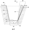
- Fig. 4 shows in a cross-section view an exemplary article (400) having a chamber (410), and a chamber annex (420) for receiving an aspirating pipette (440), and optionally a porous membrane (480), for example, a high throughput screening membrane insert or liner, for dividing the chamber into upper (410a) and lower (410b) chambers, or upper and lower chamber volumes.
- the chamber annex (420) or chamber extension is not physically separated from the main chamber (410) space, but is instead a spatial extension or expansion of the main chamber.
- dotted line (425) represents a non-physical boundary between the main chamber and the chamber annex.
- the chamber annex and the optional porous membrane provide an excellent geometry that permits aspiration of the medium without aspirating the spheroid (450) mass from the well chamber.
- the chamber annex (420) having an optional second bottom (430) or stop-ledge provides space to accommodate a pipette tip (440) of a pipette to exchange fluid medium without significantly disturbing the spheroid (450) in the transparent arcuate round bottom surface area and volume (460) of the lower chamber (410b).
- the stop ledge (430) prevents the pipette tip from entering the lower spheroid chamber.
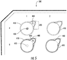
- Fig. 5 shows aspects of the exemplary article of Fig. 4 .
- Fig. 5 shows in the well area A1, a partial top or plan view (500) of the exemplary article of Fig. 4 , having a plurality of the chambers (410), each chamber having a chamber annex (420) for receiving the aspirating pipette (440).
- Fig. 5 shows in well area B1, the chamber (410) includes the optional porous membrane (480) or liner for dividing the chamber into the upper chamber and the lower chamber (410a and 410b, respectively, not shown) where the porous membrane (480) covers the underlying or hidden spheroid (450).
- An article having wells configured as shown in area B1 including the porous membrane (480) provide a functioning nested 96-well HTS Transwell® spheroid plate.
- Well plates having opaque sidewalls and gas permeable, rounded-bottom wells having clear windows can provide significant advantages including, for example: no need to transfer the spheroid from one multiwell plate (in which spheroids can be formed and visualized) to another plate for conducting assays to, for example, evaluate drug compounds; avoiding the spheroid transfer step can save time and avoid potential loss or disruption of the spheroid; and the spheroids can receive superior oxygenation with well-bottoms made from a polymer having gas permeable properties at a given wall thickness. Increased oxygen availability to the cells in the spheroid culture is particularly helpful for cells with high oxygen requirements such as hepatocytes.
- the article having a chamber having at least one concave arcuate surface can include, for example, a plurality of adjacent concave arcuate surfaces having, for example, from 1 to about 1,000 concave arcuate surfaces on the bottom of the same chamber, see for example, Figs. 7 and 8 .
- the article can be, for example, a single well or multi-well plate configuration having numerous "spheroidal wells", such as a plurality of dimples or pits in the bottom or base of each well.
- the plurality of spheroids or spheroid wells per chamber can preferably accommodate, for example, a single or one spheroid per spheroid well.
- the gas permeable, transparent well bottom having the at least one concave arcuate surface or "cup” can be, for example, a hemi-spherical surface, a conical surface having a rounded bottom, and like surface geometries, or a combination thereof.
- the well and well bottom ultimately terminates, ends, or bottoms-out in a spheroid "friendly" rounded or curved surface, such as a dimple, a pit, and like concave frusto-conicial relief surfaces, or combinations thereof.
- the opaque side wall surface i.e., a surround
- the opaque side wall surface can be, for example, a vertical cylinder or shaft, a portion of a vertical conic of decreasing diameter from the chamber top to the chamber bottom, a vertical square shaft or vertical oval shaft having a conical transition, i.e., a square or oval at the top of the well, transitioning to a conic, and ending with a bottom having at least one concave arcuate surface, i.e., rounded or curved, or a combination thereof.
- Other illustrative geometric examples include holey cylinders, holey conic cylinders, first cylinders then conics, and other like geometries, or combinations thereof.
- the article can further comprise, for example, a low-adhesion or no-adhesion coating on a portion of the chamber, such as on the at least one concave arcuate surface.
- the article can further comprise, for example, a chamber annex, chamber extension area, or an auxiliary side chamber, for receiving a pipette tip for aspiration
- the chamber annex or chamber extension e.g., a side pocket
- the chamber annex can have a second bottom spaced away from the gas-permeable, transparent bottom.
- the chamber annex and the second bottom of the chamber annex can be, for example spaced away from the gas-permeable, transparent bottom such as at a higher elevation or relative altitude.
- the second bottom of the chamber annex deflects fluid dispensed from a pipette away from the transparent bottom to avoid disrupting or disturbing the spheroid.
- the article can further comprise a porous membrane, such as a liner or membrane insert, situated within a portion of the chamber, situated within a portion of the chamber annex, or both the chamber and the chamber annex portion.
- the porous membrane can provide isolation or separation of a second cellular material, such as a different cell type or different cell state, situated in an upper portion of the chamber, in an upper portion of the chamber formed by the porous membrane, or both chambers, from first cellular material in a lower portion of one or both chambers near the transparent bottom.
- the at least one concave arcuate surface can be, for example, a hemisphere, or a portion of a hemisphere, such as a horizontal section or slice of a hemisphere, having a diameter of, for example, from about 250 to about 5,000 microns (i.e., 0.010 to 0.200 inch), including intermediate values and ranges, depending on, for example, the well geometry selected, the number of concave arcuate surfaces within each well, the number of wells in a plate, and like considerations.
- Other concave arcuate surface can have, for example, parabolic, hyperbolic, chevron, and like cross-section geometries, or combinations thereof.
- the spheroid can be, for example, substantially a sphere, having a diameter of, for example, from about 100 to about 500 microns, more preferably from about 150 to about 400 microns, even more preferably from about 150 to about 300 microns, and most preferably from about 200 to about 250 microns, including intermediate values and ranges, depending on, for example, the types of cells in the spheroid.
- Spheroid diameters can be, for example, from about 200 to about 400 microns, and the upper diameters being constrained by diffusion considerations (for a review of spheroids and spheroid vessels see Achilli, T-M, et. al. Expert Opin. Biol. Ther. (2012) 12(10 )).
- the disclosure provides a perfusion plate apparatus comprising:
- Fig. 6 shows in perspective aspects of an exemplary perfusion plate apparatus (600).
- the aforementioned perfusion plate apparatus can further comprise a porous liner (480) situated within a portion of the chamber (610), situated within a portion of the chamber annex (not shown), or both the chamber and the chamber annex, the porous liner provides isolation or separation of a second cellular material (660) such as Caco 2 cells, in an upper portion of the chamber, an upper portion of the chamber annex, or both upper portion of the chamber and the chamber annex, from first cellular material, such as a spheroid (450), situated in the lower portion of the chamber or the chamber annex and near the transparent bottom region(460).
- a second cellular material such as Caco 2 cells
- the aforementioned perfusion plate apparatus can further comprise, for example: a source liquid (not shown), a perfusion plug (655), i.e., liquid permeable material, situated in a liquid connection member (635), such as a tube, between a source well (630) and the cell culture rounded-bottom well of the apparatus (600), a perfusion plug (655) situated in a liquid connection member (645) between the cell culture rounded-bottom well and the waste well (640), or both situations.
- the waste well (640) preferably can have an arcuate bottom surface to facilitate removal of waste liquid medium (not shown) using, for example, a pipette, a vacuum pump, or like liquid removal equipment.
- a related but distinct cell culture article i.e., FloWellTM plate
- FloWellTM plate FloWellTM plate
- US Provisional Patent Application Serial No. 61/594,039 filed on Feb. 2, 2012 , now PCT/US13/24030, to Goral, et al. , entitled "Automatic continuous perfusion cell culture microplate consumables”.
- the related application mentions, for example, a microplate for culturing cells with automatic, continuous perfusion of a liquid medium, and can include, for example, a well frame which defines a plurality of cavities therethrough.
- the microplate can further include a planar substrate connected with the well frame.
- the planar substrate can provide a bottom surface to the plurality of cavities, forming a plurality of wells.
- the plurality of wells may include a first well, a second well fluidly connected with the first well, and a third well fluidly connected with the first well.
- the first well may be employed for culturing the cells in the liquid medium.
- the second well may be employed for providing an outflow or source of the liquid medium to the first well.
- the third well may be employed for receiving an inflow or waste stream of the liquid medium from the first well.
- the second well may be fluidly connected with the first well with a first perfusion membrane.
- a first perfusion membrane can be disposed in between the well frame and the planar substrate and may extend from an outlet section of the second well to an inlet section of the first well.
- the third well may be fluidly connected with the first well with a second perfusion membrane.
- the first and second perfusion membranes can have a porosity of, for example, from about 0.2 to about 200 microns.
- the second perfusion membrane can be disposed in between the well frame and the planar substrate and extend from an outlet section of the first well to an inlet section of the third well.
- the liquid medium flows from the second well through the first perfusion membrane to the first well and from the first well through the second perfusion membrane to the third well (see for example Fig. 5 therein).
- the related application also mentions methods of fabricating the microplate and methods of culturing cells.
- Fig. 7 shows aspects of an exemplary multi-spheroidal well article (700), which is pronounced of aspects of Fig. 4 including, for example, one or more chambers (410), each chamber having the chamber annex (420) area bounded by line (425) and stop-ledge (430), for receiving an aspirating pipette (not shown).
- the bottom of each chamber (410) in Fig. 7 can include a plurality of arcuate dimples (465), which dimples can be either or both transparent and gas permeable, and can each receive or cultivate a single spheroid (450).
- the multi-spheroidal well article (700) can include the optional porous membrane (480) or liner insert for dividing the chamber into the upper (410a) and the lower (410b) chamber.
- Fig. 8 shows aspects of the exemplary article of the multi-spheroidal well article (700) of Fig. 7 .
- Fig. 8 shows, in the well area A1, a top view (800) of the exemplary article of Fig. 7 , having a plurality of the chambers (410), each chamber having the chamber annex (420) for receiving the aspirating pipette (not shown).
- the bottom of each chamber (410) includes a plurality of arcuate dimples (465), which dimpled surfaces can receive or cultivate a plurality of spheroids (450). Additionally or alternatively, Fig.
- the chamber (410) includes the optional porous membrane (480) or liner insert for dividing the chamber into the upper chamber and the lower chamber (410a and 410b, respectively, not shown).
- the membrane (480) or liner insert conceals and protects the underlying spheroids (450) and spheroid wells (465) from disturbances or disruption from forces or activity above the membrane, such as during the addition or removal of liquid medium.
- the article having a chamber can include, for example, from 1 to about 2,000 chambers, from 10 to about 1,500 chambers, including intermediate values and ranges, and each chamber is physically separated from any other chamber, and each chamber has a single concave arcuate surface.
- such a multi-well plate product configuration can have, for example, one spheroid per chamber.
- the at least one concave arcuate surface can have, for example, a plurality of adjacent concave arcuate bottom surfaces within the same well.
- a single well or multi-well plate configuration can have numerous spheroidal wells, such as dimples or pits in the bottom or base of each well.
- the article can accommodate a plurality of isolated spheroids in separated spheroid wells in a single chamber, preferably having, for example, one spheroid per spheroid well.
- the disclosure provides a method of making an article, the article comprising:
- the method of making the article can further comprise, for example, inserting a porous membrane in at least one of the chambers.
- a multiwell plate having a flat well-bottom geometry can be, for example, positioned in a nest that has at each well-bottom position areas removed from the nest that have a circular perimeter in roughly the same dimensions as the well format, or the nest can have a tapered angle, for example, from about 30 to about 60 degrees, including intermediate values and ranges, such as 40 to 50, and45 degrees, turning into a radius at the apex, that is, rounded at the very bottom of the well.
- a heated platen heated for example at 180 to 400 degrees F, more preferably 250 to 300 degrees F, having an array of pins that have, for example, a matching 45 degree tapered angle from the sidewall sloping into a radius at the apex, is held stationary, with a pin positioned over each well.
- the pin-platen is actuated so that the pins descend into the wells of the multiwell plate to contact the clear flat well-bottom surface.
- Time, temperature, and pressure can change the well-bottom material geometry as the pins advance until the reformed well-bottom material meets the matching nest geometry.
- the array of pins may be coated with a release agent, such as PTFE, to prevent the reformed well-bottom geometry from sticking to the heated pins, or the pins can be uncoated.
- the nest may also have a vacuum assist on the nest to help draw the polymer into the well geometry. Cooling air can be injected into the top of the wells above the heated pins to cool the hot pins slightly and facilitate their release from the polymer of the reformed well-bottom geometry.
- the platen with the pin array and the nest with the matching geometry can be rapidly changed to comply with many multiple well formats, including 384- and 1536-wells. Any number of wells may be reformed at the same time.
- the pin-platen can be held stationary while the nest holding the insert can be actuated to be brought into contact with the stationary pin-platen. In embodiments, both the pin-platen and the nest holding the insert can be actuated to provide relative motion that achieves contact and closure between the pins and the wells of the insert.
- a v-shaped well base geometry having, for example, a tapered angle of 45 degrees, sloping from the well sidewall to a radius at the apex, is superior for spheroid formation and superior for optical measurement compared to a hemispherical well-bottom geometry.
- the v-shaped well base geometry also permits overmolding on the well base geometry using the same flat pins that can be used to over-mold opaque polymer onto a flat insert.
- the 45 degree well base tapered angle permits the pins to contact each well base on the bottom tapered sidewall. While this can also be done with a hemispherical geometry, it is more difficult. If the pin is not able to shut-off on the sidewall, the opaque polymer can leak into or onto the clear well bottom.
- the pin can be made larger than the well, and achieve shut-off on the flat area surrounding each well at the top of the insert.
- This alternative solution is not desired because it can create a flat ledge within each well upon which cells can settle. Cells that settle on the ledge cannot contribute to the spheroid in the center of the well bottom, but can cause large variation in experimental results.
- the post-forming equipment can have, for example, a heated pin, such as a single pin, a row of pins, or an array of pins, that can match the number and alignment of, for example, a single well or a plurality of wells in a row or an array of wells of an injection molded microwell plate.
- the geometry at the end of each pin can have, for example, a 45 degree angle or taper from the sidewall and have a radius at or near the apex.
- an injection molded plate having a flat well-bottom geometry can be situated and secured in a nest for the post-forming step where the heated pin or pin array assembly is pressed, for example, into the flat well-bottoms of an injection molded microplate.
- the nest can have a matching 45 degree angle at each well position to match and receive the pin shape.
- a platen can hold the heated pin or pins and the nest holds the matching well-bottom geometry.
- the plane of the pin platen and the plane of the nest can be aligned in parallel and both can be perpendicular to a common axis for proper reversible and reproducible pressing.
- the platen, the nest, or both, can be rapidly interchanged to accommodate other multiwell plate formats such as 384- and 1536-well plates.
- the platen bearing the heated pin(s) can be pressed into a matching well(s) of the multiwell plate to form the selected geometry defined by the geometry or cross-section of the pin's tip, such as hemispherical, conical, v-shaped, w-shaped, wedged shaped, and like geometries, or combined geometries, in the clear base of the well.
- the disclosure provides a method of culturing spheroids comprising, for example:
- the disclosed article can be, for example, a multiwell plate having an opaque side wall for the wells and having an arcuate or concave rounded base or bottom surface, the base or bottom surface can be gas permeable and transparent or clear to visible light.
- Polymethylpentene (TPX) of the presently disclosed gas permeable spheroid plate can be selected as a suitable base or wall material that can be used in methods of making in the '494 patent and the present disclosure.
- the structure of the presently disclosed gas permeable spheroid plate can also include one or more ridges arranged in one or more grid patterns as disclosed in the '494 patent, see for example, col. 4, line 30 to col. 5, line 54, to further reduce or prevent cross-talk.
- a film In over-molded plates without a grid, the perimeter of the well, a film, tended to peel away from the molded plate body. The grid appears to keep the film from peeling away from the plate body as it is reforming. The grid also appears to prevent stress marks from appearing in the film, since stress marks do appear in the plates without the grid.
- the multiwell plate bottom or base portion having at least one rounded, cupped, or dimpled impression in the base is injection molded, or thermoformed using a clear polymer.
- the molded or thermoformed clear multiwell bottom plate is inserted into a vertical press, then an opaque polymer is injected forming the remainder of the multiwell plate onto the clear, round well bottoms.
- An alternative to insert molding uses a 2-shot molding process.
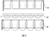
- Fig. 1 schematically shows methods for joining preformed or molded components.
- An injection molded or thermoformed opaque, holey plate portion (110) of a multiwell plate i.e., without well bottoms
- This joining to form the article (130) can be accomplished by any suitable method, for example, by placing the well-bottom plate (120) (or "insert") into a vertical press and molding the opaque holey plate portion (110) onto the well-bottom plate portion.
- An alternative method of making can be, for example, injection molding the entire multiwell plate using a 2-shot molding process. The methods form an integral multiwell plate that has clear, rounded-well bottoms and opaque sidewalls.
- Any method of joinery can be used to attach preformed portions (110) and (120), including, for example, adhesive, ultrasonic, thermal, IR, laser welding, and like methods, or combinations thereof.
- Subsequent optional well coating with, for example, an ultra-low attachment material, and the force of gravity, can facilitate the cells self-assembling into a spheroid.
- Using a gas permeable material of appropriate thickness for, at least, the clear, round or cupped well-bottom portion of the multiwell plate enhances oxygen availability for the cells in the spheroid.
- Figs. 2A to 2C show an alternative method for creating an opaque "sleeve.”
- Fig. 2A shows an injection molded, or thermoformed well portion of a multiwell plate (210)(no skirt) having rounded or cupped well bottoms made using a clear polymer.
- Fig. 2B shows an injection molded, or thermoformed second multiwell plate including the skirt (220) but without well bottoms made using an opaque polymer.
- the well diameters of the opaque plate (220) are molded to be slightly larger than the well diameters of the clear plate (210).
- the clear portion is slipped into the opaque portion and may be permanently attached via a number of suitable methods including, for example, an adhesive, ultrasonic welding, IR welding, thermal welding, laser welding, and like methods.
- Fig. 2C shows a compression fit of the clear plate into the opaque plate to provide the assembled plate article (230).
- the opaque plate (220) acts as a sleeve structure to receive the clear plate structure and the combination forms the article having wells having opaque sidewalls and a clear window at the arcuate or rounded base of the well.
- Fig. 3 shows another alternative method of making the disclosed article using distortion printing.
- a clear polymer sheet (310) is selectively printed with an opaque material to form printed sheet (315) having clear window regions or zones (330).
- the sheet can be selectively thermoformed to introduce the cups (i.e., the distortion) before or after printing so that the clear zones (330) of the printed sheet (315) become the center of the well bottoms.
- two halves, for example, a holey plate having clear bottoms (350) and sheet (315) of a mold are used to form the complete multiwell plate (340) from the distortion printed polymer sheet. Once thermoformed into a multiwell plate (360), all of the plate will appear opaque except for the clear zone (370) in the cupped-shaped well bottoms that form a window for optical viewing at or from the well bottom.
- one can mold or thermoform an opaque multiwell plate that has no well-bottoms i.e., make an opaque "holey plate”
- injection mold, or thermoform the multiwell plate bottom or base portion using a clear polymer one can attach the holey plate and base components together using any of various assembly processes, including, for example, adhesive, ultrasonic, IR, thermal, laser welding, and like processes.
- a multiwell plate without a skirt
- the well diameters of the opaque plate are molded to be slightly larger than the well diameters of the clear plate.
- the opaque plate acts as a sleeve to receive the clear plate and thus form opaque sidewalls and with a clear window at the base of the well.
- Non-adhesive coating The interior well-bottom surface, walls, or both can optionally be made non-adhesive to cells by coating those surfaces with a polymer that does not have any characteristics that promote cell attachment, such as a perfluorinated polymer, olefin, or like polymers, and mixtures thereof.
- a polymer that does not have any characteristics that promote cell attachment such as a perfluorinated polymer, olefin, or like polymers, and mixtures thereof.
- the interior well-bottom may be coated with a non-binding material such as an ultra-low attachment material, agarose, nonionic hydrogel, or like materials, that can inhibit cell attachment. Coatings can also be applied to the clear well bottom portion of the multiwell plate prior to joining with the opaque portion.
- a low-attachment substrate for example, a low-attachment substrate, the well curvature in the body and the base portions, and gravity, can induce cells to self-assemble into spheroids, which cell clusters are known to maintain differentiated cell function indicative of a more in-vivo like response (see Messner, et al., Archives of Toxicology, Nov. 11, 2012 ).
- Perfluorinated polymers or polymers such as poly 4-methylpentene also provide gas permeability at thicknesses normally used in molding processes, which gas permeability can be beneficial for metabolically active cell types.
- Figs. 9A and 9B show a cross-section view of the combination ( 900 ) of the injection molding pin shut-off in contact with a well-bottom having different geometries (9A; v-shaped, and 9B; hemisphere shaped).
- Fig. 9A schematically demonstrates how the pin ( 910 ), which fits inside the well, can shut-off ( 912 ) on the 45 degree angle of the v-shaped well-bottom geometry ( 915 ).
- Fig. 9B schematically demonstrates how the pin ( 910 ) can encounter potential difficulty of achieving shut-off ( 912 ) on the hemispherical well-bottom geometry ( 920 ).
- Figs. 10A and 10B show cross-section views of an alternative design for a pin shut-off.
- Figs. 10A and 10B demonstrate the utility of an optional distortion collar ( 1010 ).
- the wall thickness of the distortion collar ( 1010 ) can be, for example, from about 0.005 to 0.020 inches, and can be determined by, for example, the modulus of the polymer, and the geometric constraints of the multiwell plate.
- the distortion collar surrounds or brackets the well and is able to distort, i.e., resiliently flex and stretch, under the pressure of the injection molding pin ( 910 ) to shut-off, that is, to seal or seal-off the contoured transparent base portion from the injected opaque resin for the side walls.
- FIG. 10A shows a pin ( 910 ) centered in the well and on a common axis ( 1011 ) with the pin.
- Fig. 10B shows the pin slightly offset ( 1015 ) from the original common axis ( 1011 ) and pin axis ( 1012 ), for example as shown, to the left of center.
- the distortion collar permits the pin to still adequately shut-off or be sealed to prevent the flow of opaque side wall polymer into the clear well-bottom.
- the distortion collar yields to a greater extent to the left side and yields to a lesser extent on the right side as illustrated by the respective force vector arrows ( 1016, 1017 ).
- Post Forming Method Another method of making a well plate article of the disclosure is accomplished by thermal reforming.
- a commercially available plate for example, having standard black (opaque) side-walls and a clear flat plastic bottom is selected.
- the concave arcuate base or tapered base having a round bottom radius is formed in the well bottom.
- the outside bottom area can be, for example, preheated with IR radiation to facilitate forming the cupped or internal concave arcuate bottom radius, or the tapered base.
- FIGs. 11A to 11D show images of cell spheroids in different well-bottom geometries. The images were captured on a light microscope at 20x magnification (the reference scale equals 1,000 micrometers).
- Image 11A shows a spheroid in an all clear control 96-well plate (i.e., the walls of this comparative plate are transparent) having a full hemisphere well-bottom geometry.
- Image 11B shows a spheroid in a prototype thermally reformed 96-well plate having a v-shaped or 45 degree tapered well-bottom geometry.
- Image 11C shows a spheroid in an injection-molded single well with the v-shaped or 45 degree well-bottom geometry.
- Image 11D shows a spheroid in an injection-molded single well having a full hemisphere well-bottom geometry.
- HT-29 cells were seeded into wells including the comparative well (11A) and inventive v-shaped wells (11B and 11C) and hemisphere shaped well (11D) at a concentration of 10,000 cells per well, and incubated for 96 hours at 37 degrees C in an incubator with 5% CO 2 and 85% humidity.
- the Figs. 11A to 11D images were captured at 20x magnification on a light microscope after 96 hours of incubation.
- the cell seeding procedure generally included the following steps: trypsinize; count the cells; centrifuge to remove medium from the cells; and re-suspend the cells.
- Seeding densities can be, for example: 10k, 20k or 30 k cells per well.
- the seeding volume can be, for example, 200 microliters per well.
- Monitoring images can be recorded, for example, at 30 minutes, at 24 hrs, and at 96 hrs after seeding, including intermediate values and ranges.
- the spheroids in images 11B and 11C are in the center of the v-shaped well base.
- the spheroids in images 11A and 11D are not in the center of the hemisphere.
- the v-shaped base geometry appears to promote centering of the spheroids in the center of the well base, which centering facilitates optical visualization.
- the plates can be molded on flat inserts of, for example, polystyrene that is 0.005", which thickness is considered not gas permeable.
Abstract
a frame having a chamber including:
an opaque side wall surface;
a top aperture;
a gas-permeable, transparent bottom; and
optionally a chamber annex surface and second bottom,
and at least a portion of the transparent bottom includes at least one concave arcuate surface, is disclosed. Methods of making and using the article are also disclosed.
Description
- This application claims the benefit of priority to
U.S. Application No. 14/087906 filed on November 22, 2013 andU.S. Provisional Application No. 61/817539 filed on April 30, 2013 - The entire disclosure of any publication or patent document mentioned herein is incorporated by reference.
- The disclosure generally relates to a cell culture well article and methods of making and using the article
- In embodiments, the disclosure provides a well article for culturing and assaying, for example, spheroidal cell masses. The well article includes at least one chamber having an opaque side wall; a transparent, round or concave bottom surface; and the transparent bottom is gas-permeable.
- In embodiments, the disclosure provides methods for making the well article, and methods of using the well article in spheroid cell culture or in cellular assays.
- In embodiments, the disclosure also provides a multi-well plate article having wells or chambers with opaque walls and a gas-permeable, transparent round-bottom, and methods for making the round-bottom multi-well plate article. The transparent round-bottom, such as an optically clear bottom window, permits convenient microscopic visualization or examination of the cultured spheroid cell mass.
- In embodiments, the disclosure provides a well plate having a base, the base having a conical or tapered geometry, such as a forty five degree (45°) angle, or like taper angles, from the sidewall to a radius at the apex (i.e., the very bottom of the well) to provide a round-bottom well or multiwell plate having an opaque sidewall and an optically clear window or base for optical visualization, such as with a microscopic or like devices, of a spheroid cell culture.
- In embodiments of the disclosure:
-
Fig. 1 schematically shows methods for joining preformed or molded components to make examples of the disclosed articles. -
Figs. 2A to 2C show an alternative method for making a disclosed article having an opaque sleeve or chamber wall surface and a pre-formed clear base insert. -
Fig. 3 shows another alternative method of making the disclosed article using distortion printing. -
Fig. 4 shows in a cross-section view of a single well or single chamber in the frame of an alternative exemplary article (400). -
Fig. 5 shows in a partial top or plan view aspects of the exemplary article ofFig. 4 . -
Fig. 6 shows in perspective aspects of an exemplary perfusion plate apparatus (600). -
Fig. 7 shows in a cross-section view aspects of an exemplary multi-spheroidal well article (700). -
Fig. 8 shows in a partial top or plan view aspects of the exemplary article of the multi-spheroidal well article (700) ofFig. 7 . -
Figs. 9A and 9B show a cross-section view of the combination (900) of the injection molding pin shut-off in contact with a well-bottom having different geometries. -
Figs. 10A and 10B show cross-section views of an alternative design for a pin shut-off. -
Figs. 11A to 11D show images of cell spheroids in alternative well-bottoms having different geometries. - Various embodiments of the disclosure will be described in detail with reference to drawings, if any. Reference to various embodiments does not limit the scope of the invention, which is limited only by the scope of the claims attached hereto. Additionally, any examples set forth in this specification are not limiting and merely set forth some of the many possible embodiments of the claimed invention.
- In embodiments, the disclosed apparatus and the disclosed method of making and using the apparatus provide one or more advantageous features or aspects, including for example as discussed below. Features or aspects recited in any of the claims are generally applicable to all facets of the invention. Any recited single or multiple feature or aspect in any one claim can be combined or permuted with any other recited feature or aspect in any other claim or claims.
- "Include," "includes," or like terms means encompassing but not limited to, that is, inclusive and not exclusive.
- "About" modifying, for example, the quantity of an ingredient in a composition, concentrations, volumes, process temperature, process time, yields, flow rates, pressures, viscosities, and like values, and ranges thereof, or a dimension of a component, and like values, and ranges thereof, employed in describing the embodiments of the disclosure, refers to variation in the numerical quantity that can occur, for example: through typical measuring and handling procedures used for preparing materials, compositions, composites, concentrates, component parts, articles of manufacture, or use formulations; through inadvertent error in these procedures; through differences in the manufacture, source, or purity of starting materials or ingredients used to carry out the methods; and like considerations. The term "about" also encompasses amounts that differ due to aging of a composition or formulation with a particular initial concentration or mixture, and amounts that differ due to mixing or processing a composition or formulation with a particular initial concentration or mixture.
- "Optional" or "optionally" means that the subsequently described event, circumstance, or structure, can or cannot occur, and that the description includes instances where the event, circumstance, or structure, occurs and instances where it does not.
- "Consisting essentially of" or "consisting of' in embodiments can refer to, for example:
- a spheroid cell culture article having:
a frame having a chamber or a plurality of chambers, for example, a well, each chamber having:- an opaque side wall surface, such as a well having an opaque side wall;
- a top aperture for operational access to the chamber;
- a gas-permeable, transparent bottom surface; and
- optionally a porous membrane insert in at least one of the chambers,
- a method of making the abovementioned spheroid cell culture article including:
- combining the gas-permeable, transparent arcuate bottom surface portion and an opaque side wall surface portion to form the article, wherein the combining is accomplished with any of the methods disclosed herein or any other suitable methods; and
- optionally inserting a porous membrane liner in at least one of the chambers; and
- a method of using the article for culturing spheroids including:
- charging the disclosed spheroid cell culture article with culture media; and
- adding spheroid forming cells to the culture media, as defined herein.
- The article, the method of making the article, and the method of using the article, of the disclosure can include the components or steps listed in the claim, plus other components or steps that do not materially affect the basic and novel properties of the compositions, articles, apparatus, or methods of making and use of the disclosure, such as a particular article configuration, particular additives or ingredients, a particular agent, a particular structural material or component, a particular irradiation or temperature condition, or like structure, material, or process variable selected.
- The indefinite article "a" or "an" and its corresponding definite article "the" as used herein means at least one, or one or more, unless specified otherwise.
- Abbreviations, which are well known to one of ordinary skill in the art, may be used (e.g., "h" or "hrs" for hour or hours, "g" or "gm" for gram(s), "mL" for milliliters, and "rt" for room temperature, "nm" for nanometers, and like abbreviations).
- Specific and preferred values disclosed for components, ingredients, additives, dimensions, conditions, and like aspects, and ranges thereof, are for illustration only; they do not exclude other defined values or other values within defined ranges. The apparatus and methods of the disclosure can include any value or any combination of the values, specific values, more specific values, and preferred values described herein, including explicit or implicit intermediate values and ranges.
- The formation of uniformly-sized spheroids of, for example, tumor cells, can be facilitated if the cells are cultured in a round-bottom vessel that has low-adhesion properties. Researchers from the Institute of Cancer Research in Sutton, UK, used Corning, Inc.'s, ultra-low-adhesion (ULA)-coated 96-well clear, round-bottom, polystyrene microplates to produce tumor spheroids that enabled target validation and drug evaluation (see Vinci et al., BMC Biology, 2012, 10:29). The spheroids enhanced the biological relevance of the tumor cell cultures and facilitated a range of functional assays. The round-bottom well shape along with gravity and the ultra-low attachment coat or coating, encouraged the cells to come together and self-assemble into the spheroid shape rather than to form a monolayer of cells.
- While the clear, round-bottom, ULA-coated wells of the 96-well plate were utilized with good results for migration and invasion assays due to the optical clarity of the structural polymer, evaluation of anti-cancer agents using fluorescent or luminescent detection in this plate were less optimal since the clear sidewalls added to the noise in the detected signal. While the tumor cells could be moved into opaque 96-well plates, this calls for pipetting the spheroids, which can be delicate, difficult, and time-consuming.
- In embodiments, the present disclosure provides a spheroid cell culture article comprising:
a frame having a chamber, for example, a well, comprising: - an opaque side wall surface;
- a top aperture; and
- a gas-permeable, transparent bottom surface,
- The disclosed well plate having a well base having a conical or tapered geometry is superior for injection molding of the well's opaque side wall since it is unnecessary to alter existing flat pins that have been previously used to over-mold on a flat insert (i.e., base). Injection molding with existing flat pins can also be accomplished on a well-bottom geometry having a full radius (i.e., a hemispherical or untapered base). An optional distortion collar feature on the base can enhance the ability of an existing flat pin to achieve shut-off on the well-bottom geometry.
- A well plate having the disclosed tapered or chevron shaped (e.g., a 45 degree angle from the sidewall to a radiused apex) well-bottom geometry has been successfully demonstrated for use in the formation of cell spheroids. The tapered well-base or well-bottom geometry also enables over-molding of the opaque well wall onto an insert (base) pre-formed with the tapered geometry using existing flat pins that would ordinarily be used to over-mold on a flat insert. The optional distortion collar feature integral with or attached to the insert (base) can facilitate resin flow shut-off of the injection molding pin. The well-bottom geometry can alternatively be generated by thermal-forming a polymer film prior to over-molding, or after over-molding using a thermal reforming process. Thermal reforming permits rapid change-over to generate well geometries for alternative multiple formats.
- The disclosed well plate having a tapered or chevron shaped base (e.g., an approximate 45 degree angle) is advantaged by, for example, permitting over-molding onto the insert using the same pin equipment to over-mold on a flat insert. This over-molding can be facilitated by the addition of a distortion collar that can flex to permit the pin to shut-off the polymer flow. Using the flat pin for molding results in saving time and reducing cost for the generation of this well plate product since the mold-cavity pins do not need to be modified for different well geometries or different well count formats.
- Thermal reforming permits rapid change-over to generate well geometries for many different well formats. Thermal reforming also permits design flexibility for assessment of different well geometries for each format and the ability to rapidly produce prototype or production samples for customer evaluation or specification.
- A well base having an approximate 45 degree tapered angle also allows for a smaller radiused apex, which apex centers the collection of cells that settle by gravity to form a cell spheroid, and enhances optical imaging.
- Referring to the Figures,
Fig. 4 shows in a cross-section view an exemplary article (400) having a chamber (410), and a chamber annex (420) for receiving an aspirating pipette (440), and optionally a porous membrane (480), for example, a high throughput screening membrane insert or liner, for dividing the chamber into upper (410a) and lower (410b) chambers, or upper and lower chamber volumes. The chamber annex (420) or chamber extension is not physically separated from the main chamber (410) space, but is instead a spatial extension or expansion of the main chamber. Thus, dotted line (425) represents a non-physical boundary between the main chamber and the chamber annex. The chamber annex and the optional porous membrane provide an excellent geometry that permits aspiration of the medium without aspirating the spheroid (450) mass from the well chamber. The chamber annex (420) having an optional second bottom (430) or stop-ledge provides space to accommodate a pipette tip (440) of a pipette to exchange fluid medium without significantly disturbing the spheroid (450) in the transparent arcuate round bottom surface area and volume (460) of the lower chamber (410b). The stop ledge (430) prevents the pipette tip from entering the lower spheroid chamber. -
Fig. 5 shows aspects of the exemplary article ofFig. 4 .Fig. 5 shows in the well area A1, a partial top or plan view (500) of the exemplary article ofFig. 4 , having a plurality of the chambers (410), each chamber having a chamber annex (420) for receiving the aspirating pipette (440). Additionally or alternatively,Fig. 5 shows in well area B1, the chamber (410) includes the optional porous membrane (480) or liner for dividing the chamber into the upper chamber and the lower chamber (410a and 410b, respectively, not shown) where the porous membrane (480) covers the underlying or hidden spheroid (450). An article having wells configured as shown in area B1 including the porous membrane (480) provide a functioning nested 96-well HTS Transwell® spheroid plate. - Well plates having opaque sidewalls and gas permeable, rounded-bottom wells having clear windows can provide significant advantages including, for example: no need to transfer the spheroid from one multiwell plate (in which spheroids can be formed and visualized) to another plate for conducting assays to, for example, evaluate drug compounds; avoiding the spheroid transfer step can save time and avoid potential loss or disruption of the spheroid; and the spheroids can receive superior oxygenation with well-bottoms made from a polymer having gas permeable properties at a given wall thickness. Increased oxygen availability to the cells in the spheroid culture is particularly helpful for cells with high oxygen requirements such as hepatocytes.
- In embodiments, the article having a chamber having at least one concave arcuate surface can include, for example, a plurality of adjacent concave arcuate surfaces having, for example, from 1 to about 1,000 concave arcuate surfaces on the bottom of the same chamber, see for example,
Figs. 7 and8 . - In embodiments, the article can be, for example, a single well or multi-well plate configuration having numerous "spheroidal wells", such as a plurality of dimples or pits in the bottom or base of each well. The plurality of spheroids or spheroid wells per chamber can preferably accommodate, for example, a single or one spheroid per spheroid well.
- In embodiments, the gas permeable, transparent well bottom having the at least one concave arcuate surface or "cup" can be, for example, a hemi-spherical surface, a conical surface having a rounded bottom, and like surface geometries, or a combination thereof. The well and well bottom ultimately terminates, ends, or bottoms-out in a spheroid "friendly" rounded or curved surface, such as a dimple, a pit, and like concave frusto-conicial relief surfaces, or combinations thereof.
- In embodiments, the opaque side wall surface (i.e., a surround) can be, for example, a vertical cylinder or shaft, a portion of a vertical conic of decreasing diameter from the chamber top to the chamber bottom, a vertical square shaft or vertical oval shaft having a conical transition, i.e., a square or oval at the top of the well, transitioning to a conic, and ending with a bottom having at least one concave arcuate surface, i.e., rounded or curved, or a combination thereof. Other illustrative geometric examples include holey cylinders, holey conic cylinders, first cylinders then conics, and other like geometries, or combinations thereof.
- In embodiments, the article can further comprise, for example, a low-adhesion or no-adhesion coating on a portion of the chamber, such as on the at least one concave arcuate surface.
- In embodiments, the article can further comprise, for example, a chamber annex, chamber extension area, or an auxiliary side chamber, for receiving a pipette tip for aspiration, the chamber annex or chamber extension (e.g., a side pocket) can be, for example, an integral surface adjacent to and in fluid communication with the chamber. The chamber annex can have a second bottom spaced away from the gas-permeable, transparent bottom. The chamber annex and the second bottom of the chamber annex can be, for example spaced away from the gas-permeable, transparent bottom such as at a higher elevation or relative altitude. The second bottom of the chamber annex deflects fluid dispensed from a pipette away from the transparent bottom to avoid disrupting or disturbing the spheroid.
- In embodiments, the article can further comprise a porous membrane, such as a liner or membrane insert, situated within a portion of the chamber, situated within a portion of the chamber annex, or both the chamber and the chamber annex portion. The porous membrane can provide isolation or separation of a second cellular material, such as a different cell type or different cell state, situated in an upper portion of the chamber, in an upper portion of the chamber formed by the porous membrane, or both chambers, from first cellular material in a lower portion of one or both chambers near the transparent bottom.
- In embodiments, the at least one concave arcuate surface can be, for example, a hemisphere, or a portion of a hemisphere, such as a horizontal section or slice of a hemisphere, having a diameter of, for example, from about 250 to about 5,000 microns (i.e., 0.010 to 0.200 inch), including intermediate values and ranges, depending on, for example, the well geometry selected, the number of concave arcuate surfaces within each well, the number of wells in a plate, and like considerations. Other concave arcuate surface can have, for example, parabolic, hyperbolic, chevron, and like cross-section geometries, or combinations thereof.
- In embodiments, the spheroid can be, for example, substantially a sphere, having a diameter of, for example, from about 100 to about 500 microns, more preferably from about 150 to about 400 microns, even more preferably from about 150 to about 300 microns, and most preferably from about 200 to about 250 microns, including intermediate values and ranges, depending on, for example, the types of cells in the spheroid. Spheroid diameters can be, for example, from about 200 to about 400 microns, and the upper diameters being constrained by diffusion considerations (for a review of spheroids and spheroid vessels see Achilli, T-M, et. al. Expert Opin. Biol. Ther. (2012) 12(10)).
- In embodiments, the disclosure provides a perfusion plate apparatus comprising:
- at least one cell culture article comprising:
a frame having a chamber, for example, a well, comprising:- an opaque side wall surface;
- a top aperture;
- a gas-permeable, transparent bottom surface; and
- optionally a chamber annex surface,
- the at least a portion of the bottom comprises at least one concave arcuate surface, that is, a rounded or curved surface,
- a media source well in fluid communication with at least one chamber of the cell culture article that controllably provides a source of fresh media to at least one chamber; and
- a waste well in fluid communication with the at least one chamber of the cell culture article that controllably receives waste media from cell metabolism in the at least one chamber.
-
Fig. 6 shows in perspective aspects of an exemplary perfusion plate apparatus (600). In embodiments, the aforementioned perfusion plate apparatus can further comprise a porous liner (480) situated within a portion of the chamber (610), situated within a portion of the chamber annex (not shown), or both the chamber and the chamber annex, the porous liner provides isolation or separation of a second cellular material (660) such asCaco 2 cells, in an upper portion of the chamber, an upper portion of the chamber annex, or both upper portion of the chamber and the chamber annex, from first cellular material, such as a spheroid (450), situated in the lower portion of the chamber or the chamber annex and near the transparent bottom region(460). - In embodiments, the aforementioned perfusion plate apparatus can further comprise, for example: a source liquid (not shown), a perfusion plug (655), i.e., liquid permeable material, situated in a liquid connection member (635), such as a tube, between a source well (630) and the cell culture rounded-bottom well of the apparatus (600), a perfusion plug (655) situated in a liquid connection member (645) between the cell culture rounded-bottom well and the waste well (640), or both situations. The waste well (640) preferably can have an arcuate bottom surface to facilitate removal of waste liquid medium (not shown) using, for example, a pipette, a vacuum pump, or like liquid removal equipment.
- A related but distinct cell culture article (i.e., FloWell™ plate) is disclosed in commonly owned and assigned copending application,
US Provisional Patent Application Serial No. 61/594,039, filed on Feb. 2, 2012 PCT/US13/24030, to Goral, et al. , entitled "Automatic continuous perfusion cell culture microplate consumables". The related application mentions, for example, a microplate for culturing cells with automatic, continuous perfusion of a liquid medium, and can include, for example, a well frame which defines a plurality of cavities therethrough. The microplate can further include a planar substrate connected with the well frame. The planar substrate can provide a bottom surface to the plurality of cavities, forming a plurality of wells. The plurality of wells may include a first well, a second well fluidly connected with the first well, and a third well fluidly connected with the first well. The first well may be employed for culturing the cells in the liquid medium. The second well may be employed for providing an outflow or source of the liquid medium to the first well. The third well may be employed for receiving an inflow or waste stream of the liquid medium from the first well. The second well may be fluidly connected with the first well with a first perfusion membrane. A first perfusion membrane can be disposed in between the well frame and the planar substrate and may extend from an outlet section of the second well to an inlet section of the first well. The third well may be fluidly connected with the first well with a second perfusion membrane. The first and second perfusion membranes can have a porosity of, for example, from about 0.2 to about 200 microns. The second perfusion membrane can be disposed in between the well frame and the planar substrate and extend from an outlet section of the first well to an inlet section of the third well. Upon introduction of a perfusion-initiating amount of the liquid medium into the second well, the liquid medium flows from the second well through the first perfusion membrane to the first well and from the first well through the second perfusion membrane to the third well (see for exampleFig. 5 therein). The related application also mentions methods of fabricating the microplate and methods of culturing cells. -
Fig. 7 shows aspects of an exemplary multi-spheroidal well article (700), which is reminiscent of aspects ofFig. 4 including, for example, one or more chambers (410), each chamber having the chamber annex (420) area bounded by line (425) and stop-ledge (430), for receiving an aspirating pipette (not shown). UnlikeFig. 4 , the bottom of each chamber (410) inFig. 7 can include a plurality of arcuate dimples (465), which dimples can be either or both transparent and gas permeable, and can each receive or cultivate a single spheroid (450). Cells can be seeded into the wells of the apparatus at a low density to permit single spheroid formation and cultivation in the neighboring but separated cups. The multi-spheroidal well article (700) can include the optional porous membrane (480) or liner insert for dividing the chamber into the upper (410a) and the lower (410b) chamber. -
Fig. 8 shows aspects of the exemplary article of the multi-spheroidal well article (700) ofFig. 7 .Fig. 8 shows, in the well area A1, a top view (800) of the exemplary article ofFig. 7 , having a plurality of the chambers (410), each chamber having the chamber annex (420) for receiving the aspirating pipette (not shown). The bottom of each chamber (410) includes a plurality of arcuate dimples (465), which dimpled surfaces can receive or cultivate a plurality of spheroids (450). Additionally or alternatively,Fig. 8 shows, in the well area B1, the chamber (410) includes the optional porous membrane (480) or liner insert for dividing the chamber into the upper chamber and the lower chamber (410a and 410b, respectively, not shown). The membrane (480) or liner insert conceals and protects the underlying spheroids (450) and spheroid wells (465) from disturbances or disruption from forces or activity above the membrane, such as during the addition or removal of liquid medium. - In embodiments, the article having a chamber can include, for example, from 1 to about 2,000 chambers, from 10 to about 1,500 chambers, including intermediate values and ranges, and each chamber is physically separated from any other chamber, and each chamber has a single concave arcuate surface. In embodiments, such a multi-well plate product configuration can have, for example, one spheroid per chamber.
- In embodiments, the at least one concave arcuate surface can have, for example, a plurality of adjacent concave arcuate bottom surfaces within the same well. In embodiments, a single well or multi-well plate configuration can have numerous spheroidal wells, such as dimples or pits in the bottom or base of each well. In embodiments, the article can accommodate a plurality of isolated spheroids in separated spheroid wells in a single chamber, preferably having, for example, one spheroid per spheroid well.
- In embodiments, the disclosure provides a method of making an article, the article comprising:
- a frame having a chamber, for example, a well, comprising:
- an opaque side wall surface;
- a top aperture;
- a gas-permeable, transparent bottom surface; and
- optionally a chamber annex surface having a second bottom remote from the transparent bottom surface; and
- at least a portion of the transparent bottom comprises at least one concave arcuate surface, that is, a transparent rounded or curved surface;
- the method of making comprising:
combining the gas-permeable, transparent arcuate bottom surface portion and an opaque side wall surface portion to form the article. - The method of making the article can further comprise, for example, inserting a porous membrane in at least one of the chambers.
- There are several methods that can be used to make an opaque round-bottom multiwell plate having opaque sidewalls and a base with a clear window. The multiwell plate made by Examples 1 or 2, and having flat well bottom geometry can be subsequently thermally-reformed to create an alternative well-bottom geometry. A multiwell plate having a flat well-bottom geometry can be, for example, positioned in a nest that has at each well-bottom position areas removed from the nest that have a circular perimeter in roughly the same dimensions as the well format, or the nest can have a tapered angle, for example, from about 30 to about 60 degrees, including intermediate values and ranges, such as 40 to 50, and45 degrees, turning into a radius at the apex, that is, rounded at the very bottom of the well. A heated platen, heated for example at 180 to 400 degrees F, more preferably 250 to 300 degrees F, having an array of pins that have, for example, a matching 45 degree tapered angle from the sidewall sloping into a radius at the apex, is held stationary, with a pin positioned over each well. The pin-platen is actuated so that the pins descend into the wells of the multiwell plate to contact the clear flat well-bottom surface. Time, temperature, and pressure can change the well-bottom material geometry as the pins advance until the reformed well-bottom material meets the matching nest geometry. The array of pins may be coated with a release agent, such as PTFE, to prevent the reformed well-bottom geometry from sticking to the heated pins, or the pins can be uncoated. The nest may also have a vacuum assist on the nest to help draw the polymer into the well geometry. Cooling air can be injected into the top of the wells above the heated pins to cool the hot pins slightly and facilitate their release from the polymer of the reformed well-bottom geometry. The platen with the pin array and the nest with the matching geometry can be rapidly changed to comply with many multiple well formats, including 384- and 1536-wells. Any number of wells may be reformed at the same time. In embodiments, the pin-platen can be held stationary while the nest holding the insert can be actuated to be brought into contact with the stationary pin-platen. In embodiments, both the pin-platen and the nest holding the insert can be actuated to provide relative motion that achieves contact and closure between the pins and the wells of the insert.
- A v-shaped well base geometry having, for example, a tapered angle of 45 degrees, sloping from the well sidewall to a radius at the apex, is superior for spheroid formation and superior for optical measurement compared to a hemispherical well-bottom geometry. The v-shaped well base geometry also permits overmolding on the well base geometry using the same flat pins that can be used to over-mold opaque polymer onto a flat insert. The 45 degree well base tapered angle permits the pins to contact each well base on the bottom tapered sidewall. While this can also be done with a hemispherical geometry, it is more difficult. If the pin is not able to shut-off on the sidewall, the opaque polymer can leak into or onto the clear well bottom. Alternatively, if the pin cannot achieve shut-off on the sidewall, the pin can be made larger than the well, and achieve shut-off on the flat area surrounding each well at the top of the insert. This alternative solution is not desired because it can create a flat ledge within each well upon which cells can settle. Cells that settle on the ledge cannot contribute to the spheroid in the center of the well bottom, but can cause large variation in experimental results.
- In embodiments, the post-forming equipment can have, for example, a heated pin, such as a single pin, a row of pins, or an array of pins, that can match the number and alignment of, for example, a single well or a plurality of wells in a row or an array of wells of an injection molded microwell plate. The geometry at the end of each pin can have, for example, a 45 degree angle or taper from the sidewall and have a radius at or near the apex.
- In embodiments, an injection molded plate having a flat well-bottom geometry can be situated and secured in a nest for the post-forming step where the heated pin or pin array assembly is pressed, for example, into the flat well-bottoms of an injection molded microplate. The nest can have a matching 45 degree angle at each well position to match and receive the pin shape. In embodiments, a platen can hold the heated pin or pins and the nest holds the matching well-bottom geometry. The plane of the pin platen and the plane of the nest can be aligned in parallel and both can be perpendicular to a common axis for proper reversible and reproducible pressing.
- The platen, the nest, or both, can be rapidly interchanged to accommodate other multiwell plate formats such as 384- and 1536-well plates. The platen bearing the heated pin(s) can be pressed into a matching well(s) of the multiwell plate to form the selected geometry defined by the geometry or cross-section of the pin's tip, such as hemispherical, conical, v-shaped, w-shaped, wedged shaped, and like geometries, or combined geometries, in the clear base of the well.
- In embodiments, the disclosure provides a method of culturing spheroids comprising, for example:
- charging any of the aforementioned articles with culture media; and
- adding spheroid forming cells to the culture media.
- There are several methods that can be used to make the disclosed article or articles. In embodiments, the disclosed article can be, for example, a multiwell plate having an opaque side wall for the wells and having an arcuate or concave rounded base or bottom surface, the base or bottom surface can be gas permeable and transparent or clear to visible light.
- Commonly owned and assigned
US 7,674,346 , mentions methods of making well plates such as bonding a polymeric holey plate to a glass or polymeric base and using, for example, heat or radiation to weld a gas permeable thin film to a holey plate to form the bottom of microplates (see e.g.,col 2, lines 4 to 44). - Commonly owned and assigned
US 5,759,494 , mentions methods of making well plates having opaque sidewalls by, for example, over-molding inserts to prevent cross-talk. Polymethylpentene (TPX) of the presently disclosed gas permeable spheroid plate can be selected as a suitable base or wall material that can be used in methods of making in the '494 patent and the present disclosure. - In embodiments, the structure of the presently disclosed gas permeable spheroid plate can also include one or more ridges arranged in one or more grid patterns as disclosed in the '494 patent, see for example, col. 4, line 30 to col. 5, line 54, to further reduce or prevent cross-talk. In over-molded plates without a grid, the perimeter of the well, a film, tended to peel away from the molded plate body. The grid appears to keep the film from peeling away from the plate body as it is reforming. The grid also appears to prevent stress marks from appearing in the film, since stress marks do appear in the plates without the grid.
-
US 6,811,752 , mentions methods of making a device having micro-chambers and microfluidic flow, and gas permeable, liquid impermeable membranes. - In one method (insert molding), the multiwell plate bottom or base portion having at least one rounded, cupped, or dimpled impression in the base is injection molded, or thermoformed using a clear polymer. Next, the molded or thermoformed clear multiwell bottom plate is inserted into a vertical press, then an opaque polymer is injected forming the remainder of the multiwell plate onto the clear, round well bottoms. An alternative to insert molding uses a 2-shot molding process.
- Referring again to the Figures,
Fig. 1 schematically shows methods for joining preformed or molded components. An injection molded or thermoformed opaque, holey plate portion (110) of a multiwell plate (i.e., without well bottoms) is joined to the injection molded or thermoformed clear, round, well-bottom plate portion (120). This joining to form the article (130) can be accomplished by any suitable method, for example, by placing the well-bottom plate (120) (or "insert") into a vertical press and molding the opaque holey plate portion (110) onto the well-bottom plate portion. An alternative method of making can be, for example, injection molding the entire multiwell plate using a 2-shot molding process. The methods form an integral multiwell plate that has clear, rounded-well bottoms and opaque sidewalls. Any method of joinery can be used to attach preformed portions (110) and (120), including, for example, adhesive, ultrasonic, thermal, IR, laser welding, and like methods, or combinations thereof. Subsequent optional well coating with, for example, an ultra-low attachment material, and the force of gravity, can facilitate the cells self-assembling into a spheroid. Using a gas permeable material of appropriate thickness for, at least, the clear, round or cupped well-bottom portion of the multiwell plate enhances oxygen availability for the cells in the spheroid. - The following examples serve to more fully describe the manner of using the above-described disclosure, and to further set forth best modes contemplated for carrying out various aspects of the disclosure. These examples do not limit the scope of this disclosure, but rather are presented for illustrative purposes. The working example(s) further describe(s) how to prepare the disclosed cell culture well articles.
- Injection Mold or Thermoform Methods
Figs. 2A to 2C show an alternative method for creating an opaque "sleeve."Fig. 2A shows an injection molded, or thermoformed well portion of a multiwell plate (210)(no skirt) having rounded or cupped well bottoms made using a clear polymer.Fig. 2B shows an injection molded, or thermoformed second multiwell plate including the skirt (220) but without well bottoms made using an opaque polymer. The well diameters of the opaque plate (220) are molded to be slightly larger than the well diameters of the clear plate (210). The clear portion is slipped into the opaque portion and may be permanently attached via a number of suitable methods including, for example, an adhesive, ultrasonic welding, IR welding, thermal welding, laser welding, and like methods.Fig. 2C shows a compression fit of the clear plate into the opaque plate to provide the assembled plate article (230). The opaque plate (220) acts as a sleeve structure to receive the clear plate structure and the combination forms the article having wells having opaque sidewalls and a clear window at the arcuate or rounded base of the well. -
Fig. 3 shows another alternative method of making the disclosed article using distortion printing. A clear polymer sheet (310) is selectively printed with an opaque material to form printed sheet (315) having clear window regions or zones (330). The sheet can be selectively thermoformed to introduce the cups (i.e., the distortion) before or after printing so that the clear zones (330) of the printed sheet (315) become the center of the well bottoms. In embodiments, two halves, for example, a holey plate having clear bottoms (350) and sheet (315) of a mold are used to form the complete multiwell plate (340) from the distortion printed polymer sheet. Once thermoformed into a multiwell plate (360), all of the plate will appear opaque except for the clear zone (370) in the cupped-shaped well bottoms that form a window for optical viewing at or from the well bottom. - In another method of making, one can mold or thermoform an opaque multiwell plate that has no well-bottoms (i.e., make an opaque "holey plate"). Next, one can injection mold, or thermoform the multiwell plate bottom or base portion using a clear polymer. Then one can attach the holey plate and base components together using any of various assembly processes, including, for example, adhesive, ultrasonic, IR, thermal, laser welding, and like processes.
- In another method of making, one can injection mold, or thermoform the entire well of a multiwell plate (without a skirt) using a clear polymer. Next, one can injection mold, or thermoform another multiwell plate (including the skirt) but without well bottoms using an opaque polymer. The well diameters of the opaque plate are molded to be slightly larger than the well diameters of the clear plate. The opaque plate acts as a sleeve to receive the clear plate and thus form opaque sidewalls and with a clear window at the base of the well.
- In another method of making, one can distortion print an opaque coating on the exterior of a clear polymer sheet, leaving a clear zone in the area that will be thermoformed with, for example, a cup or dimple, or multiples thereof, into the center of the well bottom. Once thermoformed into a multiwell plate, all of the plate will appear opaque except for the clear zone that forms a window for optical viewing.
- Non-adhesive coating The interior well-bottom surface, walls, or both can optionally be made non-adhesive to cells by coating those surfaces with a polymer that does not have any characteristics that promote cell attachment, such as a perfluorinated polymer, olefin, or like polymers, and mixtures thereof. Alternatively, following assembly of the opaque multiwell plate with clear, round or cupped well-bottoms, the interior well-bottom may be coated with a non-binding material such as an ultra-low attachment material, agarose, nonionic hydrogel, or like materials, that can inhibit cell attachment. Coatings can also be applied to the clear well bottom portion of the multiwell plate prior to joining with the opaque portion. The combination of, for example, a low-attachment substrate, the well curvature in the body and the base portions, and gravity, can induce cells to self-assemble into spheroids, which cell clusters are known to maintain differentiated cell function indicative of a more in-vivo like response (see Messner, et al., Archives of Toxicology, Nov. 11, 2012). Perfluorinated polymers or polymers such as poly 4-methylpentene also provide gas permeability at thicknesses normally used in molding processes, which gas permeability can be beneficial for metabolically active cell types. Representative thickness and ranges of gas permeable polymer can be, for example, from about 0.001 inch to about 0.025 inch, from 0.0015 inch to about 0.03 inch, including intermediate values and ranges (where 1 inch = 25,400 microns; 0.000039 inches = 1 micron). Additionally or alternatively, other materials having high gas permeabilities, such as polydimethylsiloxane polymers, can provide sufficient gas diffusion at a thickness, for example, of up to about 1 inch.
-
Figs. 9A and 9B show a cross-section view of the combination (900) of the injection molding pin shut-off in contact with a well-bottom having different geometries (9A; v-shaped, and 9B; hemisphere shaped).Fig. 9A schematically demonstrates how the pin (910), which fits inside the well, can shut-off (912) on the 45 degree angle of the v-shaped well-bottom geometry (915).Fig. 9B schematically demonstrates how the pin (910) can encounter potential difficulty of achieving shut-off (912) on the hemispherical well-bottom geometry (920). -
Figs. 10A and 10B show cross-section views of an alternative design for a pin shut-off.Figs. 10A and 10B demonstrate the utility of an optional distortion collar (1010). The wall thickness of the distortion collar (1010) can be, for example, from about 0.005 to 0.020 inches, and can be determined by, for example, the modulus of the polymer, and the geometric constraints of the multiwell plate. The distortion collar surrounds or brackets the well and is able to distort, i.e., resiliently flex and stretch, under the pressure of the injection molding pin (910) to shut-off, that is, to seal or seal-off the contoured transparent base portion from the injected opaque resin for the side walls.Fig. 10A shows a pin (910) centered in the well and on a common axis (1011) with the pin.Fig. 10B shows the pin slightly offset (1015) from the original common axis (1011) and pin axis (1012), for example as shown, to the left of center. The distortion collar permits the pin to still adequately shut-off or be sealed to prevent the flow of opaque side wall polymer into the clear well-bottom. The distortion collar yields to a greater extent to the left side and yields to a lesser extent on the right side as illustrated by the respective force vector arrows (1016, 1017). - Post Forming Method Another method of making a well plate article of the disclosure is accomplished by thermal reforming. In the thermal reforming method a commercially available plate, for example, having standard black (opaque) side-walls and a clear flat plastic bottom is selected. Using a combination of vacuum on the outside and pressure supplied by a hot forming tool with a full radius pushed into the interior of the well(s) on the opposite side of the plate and further into the bottom of the well, the concave arcuate base or tapered base having a round bottom radius is formed in the well bottom. The outside bottom area can be, for example, preheated with IR radiation to facilitate forming the cupped or internal concave arcuate bottom radius, or the tapered base.
- Method of Use; Culturing of Cells
Figs. 11A to 11D show images of cell spheroids in different well-bottom geometries. The images were captured on a light microscope at 20x magnification (the reference scale equals 1,000 micrometers). - Image 11A shows a spheroid in an all clear control 96-well plate (i.e., the walls of this comparative plate are transparent) having a full hemisphere well-bottom geometry.
- Image 11B shows a spheroid in a prototype thermally reformed 96-well plate having a v-shaped or 45 degree tapered well-bottom geometry.
- Image 11C shows a spheroid in an injection-molded single well with the v-shaped or 45 degree well-bottom geometry.
- Image 11D shows a spheroid in an injection-molded single well having a full hemisphere well-bottom geometry.
- HT-29 cells were seeded into wells including the comparative well (11A) and inventive v-shaped wells (11B and 11C) and hemisphere shaped well (11D) at a concentration of 10,000 cells per well, and incubated for 96 hours at 37 degrees C in an incubator with 5% CO2 and 85% humidity. The
Figs. 11A to 11D images were captured at 20x magnification on a light microscope after 96 hours of incubation. - The cell seeding procedure generally included the following steps: trypsinize; count the cells; centrifuge to remove medium from the cells; and re-suspend the cells. Seeding densities can be, for example: 10k, 20k or 30 k cells per well. The seeding volume can be, for example, 200 microliters per well. Monitoring images can be recorded, for example, at 30 minutes, at 24 hrs, and at 96 hrs after seeding, including intermediate values and ranges.
- The spheroids in images 11B and 11C are in the center of the v-shaped well base. The spheroids in images 11A and 11D are not in the center of the hemisphere. The v-shaped base geometry appears to promote centering of the spheroids in the center of the well base, which centering facilitates optical visualization.
- In embodiments, one can form a gas permeable, rounded well-bottom using the thermal reforming process. In existing methods, the plates can be molded on flat inserts of, for example, polystyrene that is 0.005", which thickness is considered not gas permeable. However, during the thermal reforming process, one can decrease the thickness of the insert at the radiused apex to, for example, about 0.003" (photograph not included), which makes the well-bottom as gas permeable as the HYPER-product film (which is also 0.003" thick polystyrene).
- The disclosure has been described with reference to various specific embodiments and techniques. However, it should be understood that many variations and modifications are possible while remaining within the scope of the disclosure.
- Aspects of the invention will now be disclosed by way of clauses below:
-
Clause 1. A cell culture article comprising:
a frame having a chamber comprising:- an opaque side wall surface;
- a top aperture; and
- a gas-permeable, liquid impermeable transparent bottom surface adjacent the opaque side wall surface, wherein at least a portion of the bottom surface comprises at least one concave arcuate surface.
-
Clause 2. The article ofclause 1 further comprising a low-adhesion or no-adhesion coating on the at least one concave arcuate surface. -
Clause 3. The article of any ofclauses 1 to 2 further comprising a chamber annex for receiving a pipette tip for aspiration, the chamber annex comprises a surface adjacent to and in fluid communication with the chamber, the chamber annex having a second bottom spaced away and at an elevation above the gas-permeable, transparent bottom, and the second bottom in use deflects fluid dispensed from a pipette away from the transparent bottom. - Clause 4. The article of any of
clauses 1 to 3 further comprising a porous membrane situated within a portion of the chamber, situated within a portion of the auxiliary second chamber, or both the chamber and the auxiliary second chamber, the porous membrane providing isolation or separation of second cellular material in an upper portion of the chamber, in an upper portion of the auxiliary second chamber, or both chambers, from the first cellular material in a lower portion of one or both chambers near the transparent bottom. - Clause 5. The article of any of
clauses 1 to 4 wherein the chamber comprises from 1 to about 1,000 chambers, each chamber is physically separated from any other chamber, and each chamber has a single concave arcuate surface. - Clause 6 The article of any of
clauses 1 to 5 wherein the at least one concave arcuate surface comprises a plurality of adjacent concave arcuate surfaces within the same chamber. - Clause 7. The article of any of
clauses 1 to 6 wherein the at least one concave arcuate surface comprises a hemi-spherical surface, a conical surface having a taper of 30 to about 60 degrees from the opaque side walls to the transparent rounded bottom, or a combination thereof. - Clause 8. The article of any of
clauses 1 to 7 wherein the opaque side wall surface comprises a vertical cylinder, a portion of a vertical conic of decreasing diameter from the chamber's top to bottom surface, a vertical square shaft having a conical transition to the at least one concave arcuate bottom surface, or a combination thereof. - Clause 9. The article of any of
clauses 1 to 8 wherein the at least one concave arcuate surface comprises a hemisphere, or a portion thereof, having a diameter of from about 250 to about 5,000 microns. - Clause 10. A perfusion plate apparatus comprising:
- at least one cell culture article of
clause 1; - a media source well in fluid communication with at least one chamber of the cell culture article that controllably provides a source fresh media to at least one chamber; and
- a waste well in fluid communication with the at least one chamber of the cell culture article that controllably receives waste media from cell metabolism in the at least one chamber.
- at least one cell culture article of
- Clause 11. The apparatus of clause 10 further comprising a porous liner situated within a portion of the chamber, situated within a portion of the auxiliary second chamber, or both the chamber and the auxiliary second chamber, the porous liner providing isolation or separation of second cellular material in an upper portion of the chamber, an upper portion of the auxiliary second chamber, or both chambers, from first cellular material in a lower portion of one or both chambers near the transparent bottom.
- Clause 12. The apparatus of any of clauses 10 to 11 further comprising: a perfusion plug situated between the source well and the cell culture article, a perfusion plug situated between the cell culture article and the waste well, or both situations.
- Clause 13. The apparatus of any of clauses 10 to 12 wherein the at least one concave arcuate surface comprises a plurality of adjacent concave arcuate surfaces.
- Clause 14. A method of making the article of
clause 1 comprising:
combining the gas-permeable, transparent, arcuate bottom surface portion and an opaque side wall surface portion to form the article. - Clause 15. The method of clause 14 wherein combining is accomplished with: injection molding, thermal reforming, post forming, distortion printing, over molding, or combinations thereof.
- Clause 16. The method of any of clauses 14 to 15 wherein the gas-permeable, transparent, arcuate bottom surface portion includes a distortion collar to prevent opaque side wall material from entering the arcuate bottom surface portion.
- Clause 17. The method of any of clauses 14 to 15 further comprising inserting a porous membrane in at least one of the chambers of the resulting article.
- Clause 18. A method of culturing spheroids comprising:
- charging the article of
clause 1 with culture media; and - adding spheroid forming cells to the culture media.
- charging the article of
- Clause 19. The method of clause 18 further comprising optically examining the cultured spheroid forming cells through the transparent bottom surface.
Claims (15)
- A cell culture article comprising:
a chamber comprising:a side wall;a top aperture; anda gas-permeable, liquid impermeable bottom comprising at least one concave surface, wherein at least a portion of the bottom is transparent and wherein at least a portion of the bottom comprises a low-adhesion or no-adhesion material in or on the at least one concave surface. - The article of claim 1, further comprising a liner having a porous membrane situated within a portion of the chamber to divide the chamber into an upper chamber and a lower chamber.
- The article of claim 1, wherein the side wall is opaque.
- The article of claim 1, further comprising a chamber annex for receiving a pipette tip for aspiration, the chamber annex comprises a surface adjacent to and in fluid communication with the chamber, the chamber annex having a second bottom spaced away and at an elevation above the gas-permeable, transparent bottom, wherein the second bottom deflects fluid dispensed from a pipette away from the transparent bottom, optionally further comprising a liner having a porous membrane situated within a portion of the chamber to form an upper chamber and a lower chamber the porous membrane providing separation of a second cellular material in the upper chamber, from a first cellular material in the lower chamber.
- The article of claim 1, wherein either:(i) the article comprises from 1 to about 2,000 of said chambers, wherein each chamber is physically separated from any other chamber;(ii) the at least one concave surface comprises a plurality of concave surfaces within the same chamber; or(iii) the at least one concave surface comprises a hemi-spherical surface, a conical surface having a taper of 30 to about 60 degrees from the side walls to the bottom, or a combination thereof.
- The article of claim 1, wherein either(i) the side wall surface comprises a vertical cylinder, a portion of a vertical conic of decreasing diameter from the chamber's top to bottom surface, a vertical square shaft having a conical transition to the at least one concave bottom surface, or a combination thereof;(ii) the at least one concave surface comprises a hemisphere, or a portion thereof, having a diameter of from about 250 to about 5,000 microns.
- A perfusion plate apparatus comprising:at least one cell culture article of claim 1;a media source well in fluid communication with at least one chamber of the cell culture article that controllably provides a source fresh media to the at least one chamber; anda waste well in fluid communication with the at least one chamber of the cell culture article that controllably receives waste media from the at least one chamber.
- The apparatus of claim 7, further comprising a porous liner situated within a portion of the at least one chamber to form an upper chamber and a lower chamber, the porous liner providing separation of a second cellular material in the upper portion of the chamber, from a first cellular material in the lower chamber.
- The apparatus of claim 7, further comprising: a perfusion plug between the source well and the at least one chamber, a perfusion plug between the at least one chamber and the waste well, or both.
- The apparatus of claim 7, wherein the at least one concave surface comprises a plurality of adjacent concave arcuate surfaces.
- A method of making the article of claim 1 comprising:
combining the gas-permeable, transparent, bottom portion and a side wall surface portion to form the article. - The method of claim 11, wherein either(i) combining is accomplished with: injection molding, thermal reforming, post forming, distortion printing, over molding, or combinations thereof;(ii) the gas-permeable, transparent, bottom portion includes a distortion collar integral with or attached to the gas permeable transparent bottom portion to prevent side wall material from entering the arcuate bottom portion; or(iii)the method further comprises inserting a porous membrane in at least one of the chambers of the resulting article.
- The method of claim 11 or claim 12, wherein the side wall of the article is opaque.
- A method of culturing spheroids comprising:charging the article of claim 1 with culture media; andadding spheroid forming cells to the culture media,optionally further comprising optically examining the cultured spheroid forming cells through the transparent bottom.
- The article of claim 1, wherein (i) the article further comprises culture media and a spheroid in said chamber; (ii) the article further comprises one or more auxiliary chambers in fluid communication with said chamber; or (iii) said side wall is adjacent to said transparent portion of said bottom.
Applications Claiming Priority (4)
| Application Number | Priority Date | Filing Date | Title |
|---|---|---|---|
| US201361817539P | 2013-04-30 | 2013-04-30 | |
| US14/087,906 US9790465B2 (en) | 2013-04-30 | 2013-11-22 | Spheroid cell culture well article and methods thereof |
| PCT/US2014/035635 WO2014179196A1 (en) | 2013-04-30 | 2014-04-28 | Spheroid cell culture well article and methods thereof |
| EP14727673.7A EP2992079B1 (en) | 2013-04-30 | 2014-04-28 | Well article and perfusion plate apparatus for spheroid cell culture |
Related Parent Applications (2)
| Application Number | Title | Priority Date | Filing Date |
|---|---|---|---|
| EP14727673.7A Division EP2992079B1 (en) | 2013-04-30 | 2014-04-28 | Well article and perfusion plate apparatus for spheroid cell culture |
| EP14727673.7A Division-Into EP2992079B1 (en) | 2013-04-30 | 2014-04-28 | Well article and perfusion plate apparatus for spheroid cell culture |
Publications (1)
| Publication Number | Publication Date |
|---|---|
| EP3633022A1 true EP3633022A1 (en) | 2020-04-08 |
Family
ID=51789549
Family Applications (2)
| Application Number | Title | Priority Date | Filing Date |
|---|---|---|---|
| EP19211588.9A Pending EP3633022A1 (en) | 2013-04-30 | 2014-04-28 | Well article and perfusion plate apparatus for spheroid cell culture |
| EP14727673.7A Active EP2992079B1 (en) | 2013-04-30 | 2014-04-28 | Well article and perfusion plate apparatus for spheroid cell culture |
Family Applications After (1)
| Application Number | Title | Priority Date | Filing Date |
|---|---|---|---|
| EP14727673.7A Active EP2992079B1 (en) | 2013-04-30 | 2014-04-28 | Well article and perfusion plate apparatus for spheroid cell culture |
Country Status (5)
| Country | Link |
|---|---|
| US (3) | US9790465B2 (en) |
| EP (2) | EP3633022A1 (en) |
| JP (2) | JP6703476B2 (en) |
| PL (1) | PL2992079T3 (en) |
| WO (1) | WO2014179196A1 (en) |
Cited By (1)
| Publication number | Priority date | Publication date | Assignee | Title |
|---|---|---|---|---|
| DE102021006144A1 (en) | 2021-12-13 | 2023-06-15 | BlueCat Solutions GmbH | Reaction vessel unit, method for selectively removing a liquid and for introducing a liquid containing a target substance from or into a reaction vessel of a reaction vessel unit |
Families Citing this family (57)
| Publication number | Priority date | Publication date | Assignee | Title |
|---|---|---|---|---|
| US10487310B2 (en) * | 2012-06-08 | 2019-11-26 | Riken | Vessel for culturing human ES cells |
| US9790465B2 (en) * | 2013-04-30 | 2017-10-17 | Corning Incorporated | Spheroid cell culture well article and methods thereof |
| CN107109340B (en) * | 2014-10-29 | 2021-10-22 | 康宁股份有限公司 | Spheroid capture insert |
| WO2016069885A1 (en) | 2014-10-29 | 2016-05-06 | Corning Incorporated | Perfusion bioreactor platform |
| KR102527308B1 (en) | 2014-10-29 | 2023-04-28 | 코닝 인코포레이티드 | Devices and Methods For Generation and Culture of 3D Cell Aggregates |
| JP2016093149A (en) * | 2014-11-14 | 2016-05-26 | 真志 池内 | Cell culture apparatus, and cell culture method |
| WO2016138338A1 (en) | 2015-02-27 | 2016-09-01 | Corning Incorporated | Fitted lid for multi-well plate |
| GB201506445D0 (en) * | 2015-04-16 | 2015-06-03 | Insphero Ag | System for propagating cells |
| JP2018201337A (en) * | 2015-10-28 | 2018-12-27 | 富士フイルム株式会社 | Microchemical device and analysis device |
| NL2016281B1 (en) | 2016-02-18 | 2017-08-24 | Perkinelmer Health Sciences B V | Means and methods for spheroid cell culturing and analysis. |
| JP6822769B2 (en) * | 2016-02-29 | 2021-01-27 | 米満 吉和 | Regularly arranged spheroids of the same size and their use |
| JP2017184716A (en) * | 2016-03-31 | 2017-10-12 | 東洋製罐グループホールディングス株式会社 | Cell culture containers, supporting jigs for cell culture containers, and cell culture methods |
| US20200299625A1 (en) * | 2016-04-13 | 2020-09-24 | Corning Incorporated | Biocompatible surface coating with high surface wettability properties |
| US10192144B2 (en) * | 2016-04-14 | 2019-01-29 | Research International, Inc. | Coupon reader |
| US20190144808A1 (en) * | 2016-06-06 | 2019-05-16 | The Research Foundation For The State University Of New York | Well including a pit |
| US10073346B2 (en) | 2016-07-08 | 2018-09-11 | Cypre, Inc. | Apparatus for patterning hydrogels into multi-well plates |
| EP3489345A4 (en) * | 2016-07-20 | 2019-10-16 | Nissan Chemical Corporation | Coating film having thin film step coverage and structural substrate equipped with said film |
| JP7039473B2 (en) * | 2016-07-29 | 2022-03-22 | ダイキン工業株式会社 | A method for producing differentiated cells, and a culture bag used for the method for producing the same. |
| CN106244417A (en) * | 2016-08-01 | 2016-12-21 | 通用生物系统(安徽)有限公司 | A kind of device for a large amount of plasmid extraction of high flux and manufacture method thereof |
| US20210292696A1 (en) | 2016-09-22 | 2021-09-23 | Corning Incorporated | Gravity flow cell culture devices, systems, and methods of use thereof |
| JP2020500522A (en) | 2016-11-30 | 2020-01-16 | コーニング インコーポレイテッド | Tray to support individual or multiple cell culture wells |
| EP3556844B1 (en) * | 2016-12-14 | 2023-11-01 | Hitachi High-Tech Corporation | Culture instrument |
| SG11201907277XA (en) * | 2017-02-07 | 2019-09-27 | Corning Inc | A high throughput 3d assay for immune cell and drug homing, migration and tumor cytotoxicity |
| SG11201909419XA (en) | 2017-04-10 | 2019-11-28 | TheWell Bioscience | Hydrogel for cell culture and biomedical applications |
| JP2019050798A (en) * | 2017-07-05 | 2019-04-04 | 株式会社Screenホールディングス | Sample container |
| PL3652290T3 (en) | 2017-07-14 | 2022-08-22 | Corning Incorporated | 3d cell culture vessels for manual or automatic media exchange |
| US11857970B2 (en) | 2017-07-14 | 2024-01-02 | Corning Incorporated | Cell culture vessel |
| JP7195302B2 (en) | 2017-07-14 | 2022-12-23 | コーニング インコーポレイテッド | Cell culture vessel for 3D culture and method for culturing 3D cells |
| JP7197557B2 (en) | 2017-07-14 | 2022-12-27 | コーニング インコーポレイテッド | Cell culture vessel with porous support |
| US11760965B2 (en) | 2017-10-19 | 2023-09-19 | Georgia Tech Research Corporation | Mesofluidic device for culture of cell aggregates |
| KR101965900B1 (en) * | 2017-11-03 | 2019-04-05 | 한국화학연구원 | Spheroid forming and counting apparatus and manufacturing method thereof, and counting method and culturing method of spheroid using the same |
| EP3717124A4 (en) | 2017-11-27 | 2021-08-11 | Basf Se | Microtiter plates designed for high-throughput screening of piercing-sucking pests such as arthropods |
| EP3720452A4 (en) * | 2017-12-04 | 2022-02-23 | The Administrators of The Tulane Educational Fund | Cell systems using spheroids and methods of making and using the same |
| BR112020011621B1 (en) * | 2017-12-20 | 2023-11-21 | Philip Morris Products S.A | IMPROVED CELL CULTURE DEVICE |
| EP3536402A1 (en) | 2018-03-09 | 2019-09-11 | Ibidi Gmbh | Sample chamber |
| CN111868524A (en) * | 2018-03-13 | 2020-10-30 | 康宁股份有限公司 | High-density 3D hepatocyte spheroid platform for ADME research |
| CA3102043A1 (en) * | 2018-05-30 | 2019-12-05 | Sun Bioscience Sa | Well for cultivating biological material |
| SG11202100146XA (en) * | 2018-07-10 | 2021-02-25 | Nippon Shokubai Co Ltd | Cell culture sheet |
| CN111032851B (en) | 2018-07-13 | 2024-03-29 | 康宁股份有限公司 | Microcavity dish having a sidewall with a liquid medium transfer surface |
| WO2020013851A1 (en) | 2018-07-13 | 2020-01-16 | Corning Incorporated | Fluidic devices including microplates with interconnected wells |
| JP7353263B2 (en) | 2018-07-13 | 2023-09-29 | コーニング インコーポレイテッド | Cell culture vessel with stabilization device |
| CN113906131A (en) * | 2019-05-30 | 2022-01-07 | 康宁股份有限公司 | Cell storage and transport media and transport systems and methods for cell aggregates |
| JP6826244B1 (en) * | 2019-06-21 | 2021-02-03 | 三井化学株式会社 | Culture materials and their uses |
| US20220282192A1 (en) * | 2019-08-02 | 2022-09-08 | Molecular Devices, Llc | Method and system for cultivating cells in media-exchanging wells |
| JP7415371B2 (en) | 2019-08-26 | 2024-01-17 | 株式会社島津製作所 | Cell culture imaging device and cell culture imaging method |
| EP4073224A1 (en) * | 2019-12-09 | 2022-10-19 | Universität Zürich | Multiwell, microscope-compatible device for high-throughput analysis of cell invasion |
| EP4146395A2 (en) * | 2020-05-08 | 2023-03-15 | Scienion GmbH | Assay plate with nano-vessels and sample recovery assembly |
| WO2021230750A1 (en) * | 2020-05-15 | 2021-11-18 | Universiteit Leiden | Screening plate and method for co-culturing cells |
| NL2025992B1 (en) | 2020-07-03 | 2022-03-08 | Perkinelmer Health Sciences B V | Multiwell plate for 3D cell culturing and imaging, method for manufacturing and uses thereof. |
| CN111793563A (en) * | 2020-08-12 | 2020-10-20 | 江苏信安佳医疗科技有限公司 | High-oxygen air vent plate device for organoid sphere culture |
| US20220127553A1 (en) * | 2020-10-22 | 2022-04-28 | Molecular Devices (Austria) GmbH | Microplates for automating organoid cultivation |
| EP4015619A1 (en) | 2020-12-17 | 2022-06-22 | Leica Microsystems CMS GmbH | Microplate assembly and method for transferring sample by means of a microplate assembly |
| EP4036209A1 (en) | 2021-01-29 | 2022-08-03 | Leica Microsystems CMS GmbH | Microplate for containing a plurality of samples |
| US20220373462A1 (en) * | 2021-05-14 | 2022-11-24 | MBD Co., Ltd. | Measuring method of cell migration using the rate of cell invasion |
| CN114907974A (en) * | 2021-06-25 | 2022-08-16 | 上海睿钰生物科技有限公司 | Culture device |
| DE102021214281A1 (en) | 2021-12-14 | 2023-06-15 | Robert Bosch Gesellschaft mit beschränkter Haftung | Device and method for splitting three-dimensional agglomerates |
| WO2023224099A1 (en) * | 2022-05-20 | 2023-11-23 | 公立大学法人名古屋市立大学 | Cell culture substrate and cell culture method |
Citations (11)
| Publication number | Priority date | Publication date | Assignee | Title |
|---|---|---|---|---|
| EP0307048A2 (en) * | 1987-09-11 | 1989-03-15 | Joseph Guy Cremonese | Cell culture flask utilizing a membrane barrier |
| US5759494A (en) | 1995-10-05 | 1998-06-02 | Corning Incorporated | Microplates which prevent optical cross-talk between wells |
| US5972694A (en) * | 1997-02-11 | 1999-10-26 | Mathus; Gregory | Multi-well plate |
| US6811752B2 (en) | 2001-05-15 | 2004-11-02 | Biocrystal, Ltd. | Device having microchambers and microfluidics |
| JP2009050194A (en) * | 2007-08-27 | 2009-03-12 | Sumitomo Bakelite Co Ltd | Vessel for cell aggregate-forming culture |
| US7674346B2 (en) | 2000-04-19 | 2010-03-09 | Corning Incorporated | Multi-well plate and method of manufacture |
| US20100273258A1 (en) * | 2009-04-24 | 2010-10-28 | The Ohio State University | Interactive Microenvironment System |
| CN201626959U (en) * | 2010-02-01 | 2010-11-10 | 中国农业科学院北京畜牧兽医研究所 | Micro perfusion device for cell culture |
| US20100297600A1 (en) * | 2009-05-19 | 2010-11-25 | Genx International, Inc. | Flooding dish and method for changing media in the dish in the preparation of mammalian specimen culture and for cryo-preservation, freezing, vitrification and the thawing and warming of such specimens |
| US20110129923A1 (en) * | 2003-10-08 | 2011-06-02 | Wilson John R | Cell culture methods and devices utilizing gas permeable materials |
| CA2848875A1 (en) * | 2011-09-20 | 2013-03-28 | Kuraray Co., Ltd. | Adherent cell culture method |
Family Cites Families (229)
| Publication number | Priority date | Publication date | Assignee | Title |
|---|---|---|---|---|
| US2947116A (en) | 1954-02-26 | 1960-08-02 | Wilton R Earle | Method of producing tissue culture flasks |
| US3630849A (en) | 1969-04-24 | 1971-12-28 | David B Land | Surface micro-organism contamination assays |
| US4382685A (en) | 1979-07-17 | 1983-05-10 | Techne (Cambridge) Limited | Method and apparatus for stirring particles in suspension such as microcarriers for anchorage-dependent living cells in a liquid culture medium |
| DE8309876U1 (en) | 1983-04-02 | 1983-12-22 | Biotest-Serum-Institut Gmbh, 6000 Frankfurt | TWO-PHASE BLOOD CULTURE BOTTLE |
| GB8321239D0 (en) | 1983-08-05 | 1983-09-07 | Orbec Ltd | Innoculating means |
| US4670396A (en) | 1985-05-02 | 1987-06-02 | Bioassy Systems Corporation | Vertical culture system with removable culture unit |
| US5171994A (en) | 1986-08-13 | 1992-12-15 | Northrop Corporation | Infrared staring imaging array |
| US5047347A (en) | 1987-08-17 | 1991-09-10 | Cline Martin J | Gas permeable culture flask and method for culturing mammalian cells |
| US4927764A (en) | 1987-11-17 | 1990-05-22 | Costar Corporation | Tissue culture flask |
| US4980293A (en) * | 1988-09-02 | 1990-12-25 | Multi-Technology Inc. | Dispensing reagents in a specimen well |
| US5240854A (en) | 1989-06-05 | 1993-08-31 | Berry Eric S | Continuous high-density cell culture system |
| US5712137A (en) | 1990-03-05 | 1998-01-27 | Smith & Nephew Plc | Laminate of a culture substrate on a carrier for producing an apertured wound dressing |
| GB9004911D0 (en) | 1990-03-05 | 1990-05-02 | Smith & Nephew | Cell culture products |
| DE4030699C1 (en) | 1990-09-28 | 1991-10-10 | Bruker Analytische Messtechnik Gmbh, 7512 Rheinstetten, De | |
| US5272083A (en) | 1990-10-10 | 1993-12-21 | Costar Corporation | Culture device and method of use having a detachable cell or tissue growth surface |
| US5151366A (en) | 1991-05-24 | 1992-09-29 | Invitro Scientific Products, Inc. | Cell culture flask |
| DE4132379A1 (en) | 1991-09-28 | 1993-04-08 | Kernforschungsz Karlsruhe | SUBSTRATE FOR CELL CULTURES AND CULTURE OF CELLS OR CELL AGGREGATES |
| US5272084A (en) | 1991-12-18 | 1993-12-21 | Corning Incorporated | Cell culture vessels having interior ridges and method for cultivating cells in same |
| US5319436A (en) * | 1992-05-28 | 1994-06-07 | Packard Instrument Company, Inc. | Microplate farming wells with transparent bottom walls for assays using light measurements |
| FR2697086B1 (en) | 1992-10-20 | 1994-12-09 | Thomson Csf | Method and device for inspecting transparent material. |
| IT1266389B1 (en) | 1993-02-15 | 1996-12-30 | Alberto Degrassi | CONTAINER STRUCTURE, PARTICULARLY FOR CELL CULTURES |
| US5374557A (en) | 1993-04-29 | 1994-12-20 | Verma; Kuldeep | Fermentation vessels and closures therefor |
| ATE162216T1 (en) * | 1993-05-17 | 1998-01-15 | Amersham Int Plc | DEVICE AND METHOD FOR DETECTING CELLULAR AND BIOCHEMICAL PROCESSES |
| JP2716646B2 (en) * | 1993-05-21 | 1998-02-18 | 住友ベークライト株式会社 | Method for forming cell aggregates |
| CN2186755Y (en) | 1994-03-25 | 1995-01-04 | 中国科学院成都生物研究所 | Multipurpose culture plate |
| US5487872A (en) | 1994-04-15 | 1996-01-30 | Molecular Device Corporation | Ultraviolet radiation transparent multi-assay plates |
| US5693537A (en) | 1994-06-28 | 1997-12-02 | Wilson; John R. | Compartmentalized tissue culture flask |
| US5707869A (en) | 1994-06-28 | 1998-01-13 | Wolf; Martin L. | Compartmentalized multiple well tissue culture plate |
| US5635344A (en) | 1994-12-07 | 1997-06-03 | Cedra Corp. | Shipping medium for organ-derived cells |
| US5554536A (en) | 1995-01-05 | 1996-09-10 | Millipore Investment Holdings Limited | Biological analysis device having improved contamination prevention |
| GB9509487D0 (en) | 1995-05-10 | 1995-07-05 | Ici Plc | Micro relief element & preparation thereof |
| US5710043A (en) | 1995-09-25 | 1998-01-20 | Becton Dickinson And Company | In vitro cell culture assembly |
| US5772905A (en) | 1995-11-15 | 1998-06-30 | Regents Of The University Of Minnesota | Nanoimprint lithography |
| FR2741357B1 (en) | 1995-11-22 | 1998-01-16 | Corning Inc | METHOD FOR MANUFACTURING A SUPPORT PLATE FOR A TWO-DIMENSIONAL NETWORK OF MICROWELLS, IN PARTICULAR FOR BIOLOGICAL TESTING OR CULTURE |
| JPH09234811A (en) | 1995-12-27 | 1997-09-09 | Mitsubishi Gas Chem Co Inc | Film-like or sheet-like deoxidizing multilayer body and its manufacture |
| JPH09173049A (en) * | 1995-12-27 | 1997-07-08 | Sumitomo Bakelite Co Ltd | Culturing vessel |
| US5858309A (en) | 1996-03-22 | 1999-01-12 | Corning Incorporated | Microplates with UV permeable bottom wells |
| US5783440A (en) | 1996-09-30 | 1998-07-21 | Becton Dickinson And Company | Culture vessel |
| CN1234112A (en) | 1996-10-10 | 1999-11-03 | 康宁股份有限公司 | Tool and method for transfer of drops |
| WO1998031466A1 (en) | 1997-01-17 | 1998-07-23 | Corning Incorporated | Multi-well plate |
| JPH10210966A (en) | 1997-01-29 | 1998-08-11 | Sumitomo Bakelite Co Ltd | Culture vessel |
| JPH10210866A (en) | 1997-01-30 | 1998-08-11 | Masayuki Minato | Falling prevention instrument for flowerpot not to be laid fallen even by strong wind |
| US5859896A (en) | 1997-03-05 | 1999-01-12 | Rosen; Howard B. | Telephone line automatic prefix dialer |
| DE19712484C2 (en) | 1997-03-25 | 1999-07-08 | Greiner Gmbh | Microplate with transparent bottom and process for its production |
| US5972653A (en) | 1997-09-10 | 1999-10-26 | Incyte Pharmaceuticals, Inc. | Polynucleotides encoding a protein of embryogenesis |
| CH692583A5 (en) | 1998-03-03 | 2002-08-15 | Weidmann H Ag | Culture vessel. |
| DE19825812C1 (en) | 1998-06-09 | 2000-01-13 | Gsf Forschungszentrum Umwelt | Cell culture vessel for the cultivation of non-adherent cells |
| GB9812783D0 (en) | 1998-06-12 | 1998-08-12 | Cenes Ltd | High throuoghput screen |
| GB9912641D0 (en) | 1999-05-28 | 1999-07-28 | Ashby Scient Ltd | Textured and porous silicone rubber |
| JP4315544B2 (en) | 1999-10-04 | 2009-08-19 | 日油株式会社 | Copolymer, production method thereof, medical material and ophthalmic material |
| US6521451B2 (en) | 1999-12-09 | 2003-02-18 | California Institute Of Technology | Sealed culture chamber |
| DE10019862A1 (en) | 2000-04-18 | 2001-11-08 | Cell Lining Ges Fuer Zellkulti | Method for automated medium exchange, useful in cell cultures, uses transparent, hollow perfusion cover for supply and removal of medium |
| DE10046175A1 (en) * | 2000-09-19 | 2002-03-28 | Augustinus Bader | Automatic culturing and treatment of cells, especially for diagnosis, employs cell culture plate with wells supplied with oxygen and nutrients |
| ES2259085T3 (en) | 2001-06-14 | 2006-09-16 | Millipore Corporation | MULTIPOCILLO TESTING DEVICE. |
| CA2351156A1 (en) | 2001-07-04 | 2003-01-04 | Peter W. Zandstra | A bioprocess for the generation of pluripotent cell derived cells and tissues |
| DE60236974D1 (en) | 2001-07-26 | 2010-08-19 | Transparent Inc | Cultivated cell construct with spheroids of cultured animal cells and its use |
| US6767607B2 (en) | 2001-08-09 | 2004-07-27 | Corning Incorporated | Multiwell plate having transparent well bottoms |
| AU2002363076A1 (en) | 2001-10-26 | 2003-05-06 | Virtual Arrays, Inc. | Assay systems with adjustable fluid communication |
| JP2003135056A (en) | 2001-10-30 | 2003-05-13 | Mitsuo Ochi | Method for producing tissue equivalent for transplantation and instrument for producing the same |
| JP2003180335A (en) | 2001-12-21 | 2003-07-02 | Sumitomo Bakelite Co Ltd | Storable culture vessel |
| US7262601B2 (en) | 2002-02-12 | 2007-08-28 | Bhp Billiton Innovation Pty Ltd | Aircraft equipped for airborne vector magnetic exploration surveys |
| WO2003104439A2 (en) | 2002-03-12 | 2003-12-18 | Surface Logix, Inc. | Assay device that analyzes the absorption, metabolism, permeability and/or toxicity of a candidate compound |
| AU2003223416A1 (en) | 2002-03-25 | 2003-10-13 | Condros, Inc. | Tissue analogs for in vitro testing and method of use therefor |
| US20030183958A1 (en) | 2002-03-28 | 2003-10-02 | Becton, Dickinson And Company | Multi-well plate fabrication |
| DE60313263T2 (en) | 2002-09-20 | 2007-12-27 | Becton Dickinson And Co. | roller bottle |
| JP3764959B2 (en) | 2002-10-10 | 2006-04-12 | 独立行政法人理化学研究所 | Cell culture container and cell culture method |
| EP1416303B8 (en) | 2002-10-30 | 2010-10-13 | Hitachi, Ltd. | Method for manufacturing functional substrates comprising columnar micro-pillars |
| US20040091397A1 (en) | 2002-11-07 | 2004-05-13 | Corning Incorporated | Multiwell insert device that enables label free detection of cells and other objects |
| FI115060B (en) | 2003-04-22 | 2005-02-28 | Chip Man Technologies Oy | Analysis and breeding equipment |
| KR20060004958A (en) | 2003-04-25 | 2006-01-16 | 제이에스알 가부시끼가이샤 | Biochip and biochip kit, and method of producing the same and method of using the same |
| US7425440B2 (en) | 2003-06-10 | 2008-09-16 | The Automation Partnership (Cambridge) Limited | Culture flask |
| US20050032208A1 (en) | 2003-06-18 | 2005-02-10 | Oh Steve Kah Weng | Materials and methods to produce stem cells |
| US8597597B2 (en) | 2003-06-26 | 2013-12-03 | Seng Enterprises Ltd. | Picoliter well holding device and method of making the same |
| US8148152B2 (en) | 2003-07-08 | 2012-04-03 | Axiogenesis Ag | Method for the preparation of embryoid bodies (EBs) and uses thereof |
| US20050112030A1 (en) | 2003-08-21 | 2005-05-26 | Gaus Stephanie E. | Meshwell plates |
| US8658349B2 (en) | 2006-07-13 | 2014-02-25 | Seahorse Bioscience | Cell analysis apparatus and method |
| US7186548B2 (en) | 2003-11-10 | 2007-03-06 | Advanced Pharmaceutical Sciences, Inc. | Cell culture tool and method |
| KR20060127003A (en) | 2003-12-19 | 2006-12-11 | 유니버시티 오브 워터루 | Cultured cell and method and apparatus for cell culture |
| CN104593277A (en) | 2004-03-05 | 2015-05-06 | 帝斯曼知识产权资产管理有限公司 | Process for cell culturing by continuous perfusion and alternating tangential flow |
| US8318479B2 (en) | 2004-05-19 | 2012-11-27 | Massachusetts Institute Of Technology | Perfused three-dimensional cell/tissue disease models |
| WO2006019836A1 (en) | 2004-07-22 | 2006-02-23 | Corning Incorporated | Culture flask |
| US7767446B2 (en) | 2004-09-16 | 2010-08-03 | Becton, Dickinson And Company | Perfusion bioreactors for culturing cells |
| EP1810004A1 (en) | 2004-10-18 | 2007-07-25 | Molecular Cytomics Ltd. | Current damper for the study of cells |
| JP3981929B2 (en) | 2004-10-29 | 2007-09-26 | 財団法人北九州産業学術推進機構 | Cell tissue microchip |
| KR100897223B1 (en) | 2004-11-24 | 2009-05-14 | 아사히 가라스 가부시키가이샤 | Method and device for inspecting defect of transparent plate body |
| JP4672376B2 (en) | 2005-01-11 | 2011-04-20 | 株式会社クラレ | Cell culture method with controlled extension direction |
| GB2427688A (en) | 2005-06-28 | 2007-01-03 | Inogen S A | Microwell plate |
| EP1910300A2 (en) | 2005-07-15 | 2008-04-16 | Laboratorios del Dr. Esteve S.A. | Prodrugs of pyrazoline compounds, their preparation and use as medicaments |
| US7745209B2 (en) | 2005-07-26 | 2010-06-29 | Corning Incorporated | Multilayered cell culture apparatus |
| AU2006275585A1 (en) | 2005-08-01 | 2007-02-08 | Invitrogen Corporation | Labels, containers, system and methods for providing reagents |
| EP1976972B1 (en) | 2006-01-24 | 2014-03-12 | Brown University | Cell aggregation and encapsulation device and method |
| JP4159103B2 (en) | 2006-02-21 | 2008-10-01 | Scivax株式会社 | Cell culture structure, cell culture container, structure with spheroids, container with spheroids and methods for producing them |
| US8435782B2 (en) | 2006-02-24 | 2013-05-07 | Kuraray Co., Ltd. | Cell culture container and method of producing the same |
| ITMI20061063A1 (en) | 2006-05-31 | 2007-12-01 | Mindseeds Lab S R L | METRODO AND PE SYSTEM RLA SELECTION AND MODIFICATION OF SINGLE CELLS AND THEIR SMALL AGGREGATES |
| DE102006030068A1 (en) | 2006-06-28 | 2008-01-03 | M2P-Labs Gmbh | Apparatus and method for the supply and removal of fluids in shaken microreactors arrays |
| US7745210B2 (en) | 2006-06-30 | 2010-06-29 | Corning Incorporated | Fluid flow diverter for cell culture vessel |
| JP2009542230A (en) | 2006-07-07 | 2009-12-03 | ユニバーシティ オブ マイアミ | Oxygen-enhanced cell culture platform |
| US9175254B2 (en) | 2006-07-07 | 2015-11-03 | University Of Miami | Enhanced oxygen cell culture platforms |
| US8053230B2 (en) | 2006-09-07 | 2011-11-08 | Nalge Nunc International Corporation | Culture dish with lid |
| WO2008060521A1 (en) | 2006-11-14 | 2008-05-22 | Acme Biosystems, Llc | Cell culture apparatus and associated methods |
| US20080118974A1 (en) | 2006-11-20 | 2008-05-22 | Gregory Roger Martin | Large scale cell culture vessel |
| DE202006017853U1 (en) | 2006-11-23 | 2007-01-18 | Forschungszentrum Karlsruhe Gmbh | Synthetic thermoplastic insert for a mocrotiter plate for the cultivation of different cells, comprises carrier structure, conically tapered recesses arranged in the carrier structure, and perforation and foil joint between the recesses |
| US20080176318A1 (en) | 2006-12-07 | 2008-07-24 | Wilson John R | Highly efficient devices and methods for culturing cells |
| US7897379B2 (en) | 2007-02-26 | 2011-03-01 | Corning Incorporated | Device and method for reducing bubble formation in cell culture |
| US20110086375A1 (en) | 2007-03-02 | 2011-04-14 | Mark Ungrin | Devices and methods for production of cell aggregates |
| WO2008118500A1 (en) | 2007-03-27 | 2008-10-02 | Wafergen, Inc. | Nutrient perfusion plate with heater & gas exchange for high content screening |
| KR100836827B1 (en) | 2007-04-09 | 2008-06-10 | 전남대학교산학협력단 | Cell culture dish for the embryoid body formation from embryonic stem cells |
| WO2008140295A1 (en) | 2007-05-16 | 2008-11-20 | Erasmus University Medical Center Rotterdam | Cell culture substrate, culture flasks and methods for cell cultivation employing said substrate |
| DE102007027273A1 (en) | 2007-05-24 | 2008-11-27 | Heipha Gmbh | Container for receiving nutrient media |
| FR2916451A1 (en) | 2007-05-25 | 2008-11-28 | Mhs Ind Soc Par Actions Simpli | SYSTEM FOR CULTIVATION OF BIOLOGICAL CELLS |
| US9309491B2 (en) | 2007-05-29 | 2016-04-12 | Corning Incorporated | Cell culture apparatus for co-culture of cells |
| US7800749B2 (en) | 2007-05-31 | 2010-09-21 | Corning Incorporated | Inspection technique for transparent substrates |
| KR20100059789A (en) | 2007-06-29 | 2010-06-04 | 셀룰러 다이내믹스 인터내셔널, 인코포레이티드 | Automated method and apparatus for embryonic stem cell culture |
| JP5233187B2 (en) | 2007-07-11 | 2013-07-10 | パナソニック株式会社 | Cell electrophysiological sensor |
| JP3139350U (en) | 2007-11-27 | 2008-02-14 | 株式会社クラレ | Cell culture vessel |
| CN101978041B (en) | 2008-01-25 | 2014-07-30 | 康宁股份有限公司 | Limited access multi-layer cell culture system |
| ATE481472T1 (en) | 2008-02-01 | 2010-10-15 | Eppendorf Ag | CULTURE PLATE WITH FLAP FOR SIDE VENTILATION |
| US20100112014A1 (en) | 2008-04-11 | 2010-05-06 | Gilbert Ryan J | Novel hydrogel compositions and methods of using |
| US8216828B2 (en) | 2008-05-30 | 2012-07-10 | Corning Incorporated | Assembly of cell culture vessels |
| WO2009148509A1 (en) | 2008-05-30 | 2009-12-10 | Corning Incorporated | Cell culture apparatus having different micro-well topography |
| US8178345B2 (en) | 2008-05-30 | 2012-05-15 | Corning Incorporated | Multilayer cell culture vessels |
| WO2009148507A1 (en) | 2008-05-30 | 2009-12-10 | Corning Incorporated | Cell culture apparatus having variable topography |
| WO2010006055A2 (en) | 2008-07-08 | 2010-01-14 | Wilson Wolf Manufacturing Corporation | Improved gas permeable cell culture device and method of use |
| CN102099459B (en) | 2008-07-16 | 2013-05-01 | Emd密理博公司 | A single or multitier cell culture system |
| EP2342317B1 (en) | 2008-09-22 | 2012-12-19 | University Of Zurich Prorektorat Forschung | Hanging drop plate |
| JP5578779B2 (en) | 2008-10-08 | 2014-08-27 | 国立大学法人東北大学 | Spheroid culture method and spheroid culture vessel |
| EP2344622B1 (en) | 2008-10-08 | 2017-12-20 | Agency for Science, Technology And Research | Apparatus for culturing anchorage dependent cells |
| JP5288171B2 (en) | 2008-10-31 | 2013-09-11 | 旭硝子株式会社 | Cultivation container |
| WO2010053951A1 (en) | 2008-11-05 | 2010-05-14 | Nanopoint, Inc. | Active microfluidic system for in vitro culture |
| US8956867B2 (en) | 2008-11-07 | 2015-02-17 | Wisconsin Alumni Research Foundation | Method for culturing stem cells |
| ES2343721B1 (en) | 2008-12-19 | 2011-06-06 | Histocell, S.L. | CELL TRANSPORTATION SYSTEM. |
| JP2010158214A (en) | 2009-01-09 | 2010-07-22 | Olympus Corp | Culture vessel |
| DE102009005526A1 (en) | 2009-01-20 | 2010-07-22 | Universität Duisburg-Essen | Bioreactor for biomass production by living species, comprises flat beds, which are provided for medium containing living species and have transparent and/or gas-permeable bottom, lighting device between each of the beds, and light guide |
| US20120064627A1 (en) | 2009-01-26 | 2012-03-15 | The Regents Of The University Of California | Apparatus and method for culturing stem cells |
| US8163537B2 (en) | 2009-01-27 | 2012-04-24 | Corning Incorporated | Nested permeable support device and method for using the nested permeable support device |
| DE102009013673A1 (en) | 2009-03-09 | 2010-09-16 | Eppendorf Ag | Cell culture dish |
| WO2010107497A2 (en) | 2009-03-18 | 2010-09-23 | The Regents Of The University Of California | Honeycomb shrink wells for stem cell culture |
| SG174435A1 (en) | 2009-03-26 | 2011-10-28 | Agency Science Tech & Res | Apparatus for cell or tissue culture |
| US8778669B2 (en) | 2009-07-22 | 2014-07-15 | Corning Incorporated | Multilayer tissue culture vessel |
| US8143053B2 (en) | 2009-10-26 | 2012-03-27 | Biomerieux, Inc. | Lockable cell growth chamber with antilocking feature |
| JP2013510582A (en) | 2009-11-12 | 2013-03-28 | ザ テキサス エーアンドエム ユニバーシティー システム | Spherical aggregate of mesenchymal stem cells |
| EP2522716B1 (en) | 2010-01-08 | 2019-08-28 | Sumitomo Bakelite Company Limited | Culture vessel for formation of aggregated cell mass |
| US9493733B2 (en) | 2010-01-18 | 2016-11-15 | Becton, Dickinson And Company | Container assembly |
| US8906685B2 (en) | 2010-01-28 | 2014-12-09 | The Regents Of The University Of Michigan | Hanging drop devices, systems and/or methods |
| JP2011172533A (en) | 2010-02-25 | 2011-09-08 | Fusao Komada | Method for three-dimensional high-density cell culture using microspace structure |
| SG185113A1 (en) | 2010-05-04 | 2012-12-28 | Agency Science Tech & Res | A microsieve for cells and particles filtration |
| US20130164848A1 (en) | 2010-09-08 | 2013-06-27 | Shimadzu Corporation | Cell culture container and cell culture method using the container |
| EP2617807B1 (en) | 2010-09-14 | 2020-10-21 | Agc Techno Glass Co., Ltd. | Culture substrate |
| US9260684B1 (en) | 2010-11-11 | 2016-02-16 | Stemcell Technologies Inc. | Cell culture device |
| JPWO2012077683A1 (en) | 2010-12-09 | 2014-05-19 | 旭硝子株式会社 | Glass ribbon defect measuring method and glass ribbon defect measuring system |
| EP2668263A4 (en) | 2011-01-24 | 2014-09-03 | California Stem Cell Inc | Neural cell purification for transplantation |
| TWI438273B (en) | 2011-03-08 | 2014-05-21 | Univ Chang Gung | High-throughput perfusative microfluidic cell culture wafers for miniaturized three-dimensional cell culture |
| GB201105226D0 (en) | 2011-03-29 | 2011-05-11 | Univ Leiden | Methods |
| US20140178992A1 (en) | 2011-03-30 | 2014-06-26 | National Center For Geriatrics And Gerontology | Membrane-separation-type culture device, membrane-separation-type culture kit, stem cell separation method using same, and separation membrane |
| JP2012249547A (en) | 2011-05-31 | 2012-12-20 | Oji Holdings Corp | Cell culture substrate and method for manufacturing the same |
| WO2012170232A1 (en) * | 2011-06-09 | 2012-12-13 | Bellbrook Labs, Llc | Device for washing suspended cells or particles |
| JP5853512B2 (en) | 2011-09-08 | 2016-02-09 | 大日本印刷株式会社 | Cell culture container and manufacturing method thereof |
| KR101306289B1 (en) | 2011-09-15 | 2013-09-09 | (주) 인텍플러스 | Method of inspecting plat panel |
| US9200246B2 (en) | 2011-12-01 | 2015-12-01 | Acea Biosciences, Inc. | Co-culture device assembly |
| US9862918B2 (en) | 2012-01-19 | 2018-01-09 | Yamaha Hatsudoki Kabushiki Kaisha | Well plate and suction device provided with well plate |
| WO2013116449A1 (en) | 2012-02-02 | 2013-08-08 | Corning Incorporated | Automatic continuous perfusion cell culture microplate consumables |
| CN202450098U (en) | 2012-03-09 | 2012-09-26 | 山东省农业科学院畜牧兽医研究所 | Culture bottle for primary explant culture cells |
| EP2653531A1 (en) | 2012-04-18 | 2013-10-23 | Oxyphen AG | Culture assembly |
| JP6111673B2 (en) | 2012-07-25 | 2017-04-12 | 住友電気工業株式会社 | Silicon carbide semiconductor device |
| USD685497S1 (en) | 2012-08-31 | 2013-07-02 | Corning Incorporated | Cell culture flask |
| US9573128B1 (en) | 2012-09-06 | 2017-02-21 | SciKon Innovation, Inc. | Fluidics device allowing fluid flow between a plurality of wells |
| KR20150047598A (en) | 2012-09-14 | 2015-05-04 | 스미또모 베이크라이트 가부시키가이샤 | Microwell plate |
| CN202849407U (en) | 2012-09-26 | 2013-04-03 | 无锡耐思生物科技有限公司 | Cell culture flask structure |
| US9701938B2 (en) | 2012-10-12 | 2017-07-11 | Lena Biosciences, Inc. | Intra-culture perfusion methods and applications thereof |
| KR20140048733A (en) | 2012-10-16 | 2014-04-24 | 삼성전자주식회사 | Multiwell plate and method for analyzing target material using the same |
| US9176115B2 (en) | 2012-10-26 | 2015-11-03 | The University Of Akron | Engineering individually addressable cellular spheroids using aqueous two-phase systems |
| GB2507744A (en) | 2012-11-07 | 2014-05-14 | Universitaetsklinikum Freiburg | Matrix for generating and cultivating uniform cell aggregations |
| WO2014078379A2 (en) | 2012-11-13 | 2014-05-22 | Seahorse Bioscience | Apparatus and methods for three-dimensional tissue measurements based on controlled media flow |
| JP2014132869A (en) | 2013-01-11 | 2014-07-24 | Sumitomo Bakelite Co Ltd | Cell culture vessel |
| US10072241B2 (en) | 2013-03-13 | 2018-09-11 | Innovative Surface Technologies, Inc. | Conical devices for three-dimensional aggregate(s) of eukaryotic cells |
| EP2781591B1 (en) | 2013-03-19 | 2017-05-03 | Unisense Fertilitech A/S | A tray, a system and a method for monitoring and culturing of a cell culture |
| KR20140113139A (en) | 2013-03-15 | 2014-09-24 | 고려대학교 산학협력단 | Cell spheroid culture plate |
| JPWO2014156455A1 (en) | 2013-03-28 | 2017-02-16 | 富士フイルム株式会社 | Cell culture tool |
| USD748812S1 (en) | 2013-04-12 | 2016-02-02 | Corning Incorporated | Arched cell culture flask |
| KR102234887B1 (en) | 2013-04-19 | 2021-04-01 | 주식회사 에이엔케이 | Substrate For Cell Culture |
| US9790465B2 (en) | 2013-04-30 | 2017-10-17 | Corning Incorporated | Spheroid cell culture well article and methods thereof |
| AU2014275013A1 (en) | 2013-06-05 | 2016-01-28 | Kranbuehl, David E. | Multi point method and apparatus for monitoring the aging and changes in corresponding tensile performance properties of a polymer |
| EP3006553B1 (en) | 2013-06-07 | 2020-09-02 | Corning Incorporated | Culture vessel and culture method |
| JP6307802B2 (en) | 2013-07-05 | 2018-04-11 | 株式会社Ihi | Culture vessel |
| JP2015029431A (en) | 2013-07-31 | 2015-02-16 | 大日本印刷株式会社 | Cell culture vessel |
| CN203513696U (en) | 2013-08-27 | 2014-04-02 | 浙江硕华医用塑料有限公司 | Cell culture flask |
| DE102013109450B4 (en) | 2013-08-30 | 2015-04-02 | Fraunhofer-Gesellschaft zur Förderung der angewandten Forschung e.V. | exposure apparatus |
| CN105593358B (en) | 2013-09-05 | 2021-12-21 | 伯尔尼大学 | Device for in vitro modelling of an organ tissue in vivo |
| JP2015050964A (en) | 2013-09-06 | 2015-03-19 | 住友ベークライト株式会社 | Multistage culture flask and production method of cell culture flask |
| JP6185816B2 (en) | 2013-10-11 | 2017-08-23 | Agcテクノグラス株式会社 | Cell culture vessel |
| WO2015061907A1 (en) | 2013-10-30 | 2015-05-07 | Miklas Jason | Devices and methods for three-dimensional tissue culturing |
| WO2015087369A1 (en) | 2013-12-12 | 2015-06-18 | ヤマハ発動機株式会社 | Well plate and subject selection device provided with well plate |
| WO2015134550A1 (en) | 2014-03-03 | 2015-09-11 | Kiyatec Inc. | 3d tissue culture devices and systems |
| US10392593B2 (en) | 2014-03-04 | 2019-08-27 | Pluristem Ltd. | Systems and methods for growing and harvesting cells |
| DE102014214077A1 (en) | 2014-07-18 | 2016-01-21 | Hamilton Bonaduz Ag | Laboratory containers, in particular cell culture containers, with a gas compensation line extending into the container volume |
| EP2985343A1 (en) | 2014-08-11 | 2016-02-17 | Karlsruher Institut für Technologie | In vitro-co-culturesystem |
| WO2016064757A1 (en) | 2014-10-19 | 2016-04-28 | Nortis, Inc. | Modular microfluidic system for perfused cell culture |
| KR102527308B1 (en) | 2014-10-29 | 2023-04-28 | 코닝 인코포레이티드 | Devices and Methods For Generation and Culture of 3D Cell Aggregates |
| US20170342363A1 (en) | 2014-10-29 | 2017-11-30 | Corning Incorporated | Devices and methods for generation and culture of 3d cell aggregates |
| CN107109340B (en) | 2014-10-29 | 2021-10-22 | 康宁股份有限公司 | Spheroid capture insert |
| JP2017532971A (en) | 2014-10-29 | 2017-11-09 | コーニング インコーポレイテッド | Design and manufacture of microwells to generate cell culture assemblies |
| WO2016069885A1 (en) | 2014-10-29 | 2016-05-06 | Corning Incorporated | Perfusion bioreactor platform |
| KR102460969B1 (en) | 2014-10-29 | 2022-10-31 | 코닝 인코포레이티드 | Cell culture insert |
| DE102014017728A1 (en) | 2014-12-01 | 2016-06-02 | Merck Patent Gmbh | Culture dish for micro-organisms |
| JP2016136921A (en) | 2015-01-29 | 2016-08-04 | 大日本印刷株式会社 | Cell culture container |
| JP2016136920A (en) | 2015-01-29 | 2016-08-04 | 大日本印刷株式会社 | Cell culture container |
| CN204752742U (en) | 2015-03-12 | 2015-11-11 | 广州医科大学 | Cell culture's cell culture ware can be used to to grow slowly |
| CN204702760U (en) | 2015-04-15 | 2015-10-14 | 上海诺狄生物科技有限公司 | A kind of culture dish |
| CN204714819U (en) | 2015-04-21 | 2015-10-21 | 北京青藤谷禧干细胞科技研究院有限公司 | A kind of Tissue Culture Flask of belt supporting frame |
| CN204608026U (en) | 2015-04-22 | 2015-09-02 | 广州洁特生物过滤股份有限公司 | A kind of cell with super hydrophilic growth surface embeds ware |
| CN204803327U (en) | 2015-06-30 | 2015-11-25 | 广州洁特生物过滤股份有限公司 | Ventilative cell culture dish |
| WO2017025584A1 (en) | 2015-08-12 | 2017-02-16 | Cytovac A/S | A cell cultivation method, a cell cultivation vessel, and uses thereof |
| US20170067019A1 (en) | 2015-09-07 | 2017-03-09 | Bioreactor Sciences Llc | Method of Continuous Mass Production of Progenitor Stem-like Cells Using a Bioreactor System |
| CN205990396U (en) | 2015-09-09 | 2017-03-01 | 广州市迪景微生物科技有限公司 | A kind of lid culture dish difficult for drop-off |
| WO2017047735A1 (en) | 2015-09-17 | 2017-03-23 | Agcテクノグラス株式会社 | Cell culture vessel |
| ES2615512B1 (en) | 2015-11-06 | 2018-03-15 | Universidad De Zaragoza | DEVICE AND MICROFLUIDIC SYSTEM FOR THE STUDY OF CELL CULTURES |
| CN205170866U (en) | 2015-12-08 | 2016-04-20 | 湖南人文科技学院 | No clear tape embryo culture ware |
| NL2016281B1 (en) | 2016-02-18 | 2017-08-24 | Perkinelmer Health Sciences B V | Means and methods for spheroid cell culturing and analysis. |
| US10774296B2 (en) | 2016-04-05 | 2020-09-15 | Corning Incorporated | Lidded cell culture devices with improved handling performance and methods for using same |
| CN205669029U (en) | 2016-05-09 | 2016-11-02 | 浙江硕华生命科学研究股份有限公司 | A kind of cell culture ware |
| CN205839030U (en) | 2016-07-27 | 2016-12-28 | 浙江译美生物科技有限公司 | Tissue Culture Dish |
| EP3296018A1 (en) | 2016-09-19 | 2018-03-21 | Ecole Polytechnique Fédérale de Lausanne (EPFL) | Organoid arrays |
| JP2018108032A (en) | 2016-12-28 | 2018-07-12 | Agcテクノグラス株式会社 | Culture vessel |
| JP2020517575A (en) | 2017-04-27 | 2020-06-18 | コーニング インコーポレイテッド | Curved glass forming process and system via differential heating of glass sheets |
| JP7197557B2 (en) | 2017-07-14 | 2022-12-27 | コーニング インコーポレイテッド | Cell culture vessel with porous support |
| WO2019014627A1 (en) | 2017-07-14 | 2019-01-17 | Corning Incorporated | Handling features for microcavity cell culture vessel |
| JP7250755B2 (en) | 2017-07-14 | 2023-04-03 | コーニング インコーポレイテッド | cell culture vessel |
| PL3652290T3 (en) | 2017-07-14 | 2022-08-22 | Corning Incorporated | 3d cell culture vessels for manual or automatic media exchange |
| CN111868524A (en) | 2018-03-13 | 2020-10-30 | 康宁股份有限公司 | High-density 3D hepatocyte spheroid platform for ADME research |
-
2013
- 2013-11-22 US US14/087,906 patent/US9790465B2/en not_active Expired - Fee Related
-
2014
- 2014-04-28 PL PL14727673T patent/PL2992079T3/en unknown
- 2014-04-28 WO PCT/US2014/035635 patent/WO2014179196A1/en active Application Filing
- 2014-04-28 EP EP19211588.9A patent/EP3633022A1/en active Pending
- 2014-04-28 JP JP2016511776A patent/JP6703476B2/en active Active
- 2014-04-28 EP EP14727673.7A patent/EP2992079B1/en active Active
-
2017
- 2017-09-19 US US15/708,473 patent/US11441121B2/en active Active
-
2019
- 2019-05-23 JP JP2019096680A patent/JP6715992B2/en active Active
-
2020
- 2020-08-28 US US17/005,801 patent/US20200392453A1/en active Pending
Patent Citations (11)
| Publication number | Priority date | Publication date | Assignee | Title |
|---|---|---|---|---|
| EP0307048A2 (en) * | 1987-09-11 | 1989-03-15 | Joseph Guy Cremonese | Cell culture flask utilizing a membrane barrier |
| US5759494A (en) | 1995-10-05 | 1998-06-02 | Corning Incorporated | Microplates which prevent optical cross-talk between wells |
| US5972694A (en) * | 1997-02-11 | 1999-10-26 | Mathus; Gregory | Multi-well plate |
| US7674346B2 (en) | 2000-04-19 | 2010-03-09 | Corning Incorporated | Multi-well plate and method of manufacture |
| US6811752B2 (en) | 2001-05-15 | 2004-11-02 | Biocrystal, Ltd. | Device having microchambers and microfluidics |
| US20110129923A1 (en) * | 2003-10-08 | 2011-06-02 | Wilson John R | Cell culture methods and devices utilizing gas permeable materials |
| JP2009050194A (en) * | 2007-08-27 | 2009-03-12 | Sumitomo Bakelite Co Ltd | Vessel for cell aggregate-forming culture |
| US20100273258A1 (en) * | 2009-04-24 | 2010-10-28 | The Ohio State University | Interactive Microenvironment System |
| US20100297600A1 (en) * | 2009-05-19 | 2010-11-25 | Genx International, Inc. | Flooding dish and method for changing media in the dish in the preparation of mammalian specimen culture and for cryo-preservation, freezing, vitrification and the thawing and warming of such specimens |
| CN201626959U (en) * | 2010-02-01 | 2010-11-10 | 中国农业科学院北京畜牧兽医研究所 | Micro perfusion device for cell culture |
| CA2848875A1 (en) * | 2011-09-20 | 2013-03-28 | Kuraray Co., Ltd. | Adherent cell culture method |
Non-Patent Citations (3)
| Title |
|---|
| ACHILLI, T-M, EXPERT OPIN. BIOL. THER., vol. 12, no. 10, 2012 |
| MESSNER ET AL., ARCHIVES OF TOXICOLOGY, 11 November 2012 (2012-11-11) |
| VINCI ET AL., BMC BIOLOGY, vol. 10, 2012, pages 29 |
Cited By (2)
| Publication number | Priority date | Publication date | Assignee | Title |
|---|---|---|---|---|
| DE102021006144A1 (en) | 2021-12-13 | 2023-06-15 | BlueCat Solutions GmbH | Reaction vessel unit, method for selectively removing a liquid and for introducing a liquid containing a target substance from or into a reaction vessel of a reaction vessel unit |
| WO2023110944A1 (en) | 2021-12-13 | 2023-06-22 | BlueCat Solutions GmbH | Reaction-vessel unit, and methods for selectively removing a liquid from, and for introducing a liquid containing a target substance into, a reaction vessel of a reaction-vessel unit |
Also Published As
| Publication number | Publication date |
|---|---|
| US20200392453A1 (en) | 2020-12-17 |
| JP6715992B2 (en) | 2020-07-01 |
| PL2992079T3 (en) | 2020-04-30 |
| US20140322806A1 (en) | 2014-10-30 |
| WO2014179196A1 (en) | 2014-11-06 |
| JP2016520307A (en) | 2016-07-14 |
| EP2992079A1 (en) | 2016-03-09 |
| US11441121B2 (en) | 2022-09-13 |
| US9790465B2 (en) | 2017-10-17 |
| JP2019162134A (en) | 2019-09-26 |
| JP6703476B2 (en) | 2020-06-03 |
| US20180002660A1 (en) | 2018-01-04 |
| EP2992079B1 (en) | 2020-01-08 |
Similar Documents
| Publication | Publication Date | Title |
|---|---|---|
| US20200392453A1 (en) | Spheroid cell culture article and methods thereof | |
| KR102527308B1 (en) | Devices and Methods For Generation and Culture of 3D Cell Aggregates | |
| US20190322969A1 (en) | Devices and methods for generation and culture of 3d cell aggregates | |
| CA2788575C (en) | Hanging drop devices, systems and/or methods | |
| NL2016281B1 (en) | Means and methods for spheroid cell culturing and analysis. | |
| US20120003732A1 (en) | Microfluidic cell culture systems | |
| US11680241B2 (en) | Perfusion enabled bioreactors | |
| CN103814125A (en) | Adherent cell culture method | |
| EP1851304A1 (en) | Culture device | |
| CN105907641B (en) | A kind of packaging, many condition parallel culture micro fluidic device and its application method | |
| WO2022000641A1 (en) | Super-hydrophobic micro-pit array chip, and production method therefor and device thereof | |
| US9457497B2 (en) | Microfluidic device and method of manufacturing the microfluidic device | |
| EP2597148A1 (en) | Oxygraph chamber and insertable micro-culture device and uses thereof | |
| CN219279916U (en) | Container for organoid culture | |
| US20230357688A1 (en) | Culture vessels containing 3d cell culture substrates with diffusion structures | |
| WO2022163827A1 (en) | Flow path device and method for manufacturing same | |
| WO2024050645A1 (en) | Laboratory devices and related methods | |
| WO2015101702A1 (en) | Sample holder, cell culture system and mold |
Legal Events
| Date | Code | Title | Description |
|---|---|---|---|
| PUAI | Public reference made under article 153(3) epc to a published international application that has entered the european phase |
Free format text: ORIGINAL CODE: 0009012 |
|
| STAA | Information on the status of an ep patent application or granted ep patent |
Free format text: STATUS: THE APPLICATION HAS BEEN PUBLISHED |
|
| AC | Divisional application: reference to earlier application |
Ref document number: 2992079 Country of ref document: EP Kind code of ref document: P |
|
| AK | Designated contracting states |
Kind code of ref document: A1 Designated state(s): AL AT BE BG CH CY CZ DE DK EE ES FI FR GB GR HR HU IE IS IT LI LT LU LV MC MK MT NL NO PL PT RO RS SE SI SK SM TR |
|
| STAA | Information on the status of an ep patent application or granted ep patent |
Free format text: STATUS: REQUEST FOR EXAMINATION WAS MADE |
|
| 17P | Request for examination filed |
Effective date: 20201006 |
|
| RBV | Designated contracting states (corrected) |
Designated state(s): AL AT BE BG CH CY CZ DE DK EE ES FI FR GB GR HR HU IE IS IT LI LT LU LV MC MK MT NL NO PL PT RO RS SE SI SK SM TR |
|
| STAA | Information on the status of an ep patent application or granted ep patent |
Free format text: STATUS: EXAMINATION IS IN PROGRESS |
|
| 17Q | First examination report despatched |
Effective date: 20210514 |
|
| GRAP | Despatch of communication of intention to grant a patent |
Free format text: ORIGINAL CODE: EPIDOSNIGR1 |
|
| STAA | Information on the status of an ep patent application or granted ep patent |
Free format text: STATUS: GRANT OF PATENT IS INTENDED |
|
| INTG | Intention to grant announced |
Effective date: 20240306 |