JP2019050798A - Sample container - Google Patents
Sample container Download PDFInfo
- Publication number
- JP2019050798A JP2019050798A JP2018086223A JP2018086223A JP2019050798A JP 2019050798 A JP2019050798 A JP 2019050798A JP 2018086223 A JP2018086223 A JP 2018086223A JP 2018086223 A JP2018086223 A JP 2018086223A JP 2019050798 A JP2019050798 A JP 2019050798A
- Authority
- JP
- Japan
- Prior art keywords
- cross
- section
- well
- liquid
- internal space
- Prior art date
- Legal status (The legal status is an assumption and is not a legal conclusion. Google has not performed a legal analysis and makes no representation as to the accuracy of the status listed.)
- Pending
Links
- 239000007788 liquid Substances 0.000 claims abstract description 244
- 230000007423 decrease Effects 0.000 claims description 12
- 230000000007 visual effect Effects 0.000 abstract description 2
- 238000011176 pooling Methods 0.000 abstract 1
- 210000004027 cell Anatomy 0.000 description 17
- 239000000243 solution Substances 0.000 description 17
- 238000012986 modification Methods 0.000 description 15
- 230000004048 modification Effects 0.000 description 15
- 230000002093 peripheral effect Effects 0.000 description 13
- 238000010586 diagram Methods 0.000 description 8
- 238000003384 imaging method Methods 0.000 description 8
- 238000002347 injection Methods 0.000 description 6
- 239000007924 injection Substances 0.000 description 6
- 230000000694 effects Effects 0.000 description 5
- 238000005286 illumination Methods 0.000 description 5
- 239000000463 material Substances 0.000 description 5
- 230000005499 meniscus Effects 0.000 description 5
- 238000000034 method Methods 0.000 description 5
- 238000012258 culturing Methods 0.000 description 4
- 238000013459 approach Methods 0.000 description 3
- 239000003814 drug Substances 0.000 description 3
- 239000001963 growth medium Substances 0.000 description 3
- 210000004748 cultured cell Anatomy 0.000 description 2
- 239000003550 marker Substances 0.000 description 2
- 239000011159 matrix material Substances 0.000 description 2
- 239000002207 metabolite Substances 0.000 description 2
- 239000000758 substrate Substances 0.000 description 2
- 230000005540 biological transmission Effects 0.000 description 1
- 238000004113 cell culture Methods 0.000 description 1
- 230000003247 decreasing effect Effects 0.000 description 1
- 238000007876 drug discovery Methods 0.000 description 1
- 230000008020 evaporation Effects 0.000 description 1
- 238000001704 evaporation Methods 0.000 description 1
- 238000002474 experimental method Methods 0.000 description 1
- 238000004519 manufacturing process Methods 0.000 description 1
- 239000002609 medium Substances 0.000 description 1
- 244000005700 microbiome Species 0.000 description 1
- 239000000203 mixture Substances 0.000 description 1
- 230000003287 optical effect Effects 0.000 description 1
- 239000011347 resin Substances 0.000 description 1
- 229920005989 resin Polymers 0.000 description 1
- 238000003860 storage Methods 0.000 description 1
- 238000012800 visualization Methods 0.000 description 1
- XLYOFNOQVPJJNP-UHFFFAOYSA-N water Substances O XLYOFNOQVPJJNP-UHFFFAOYSA-N 0.000 description 1
Images


Abstract
Description
この発明は、液体を含む試料を保持する試料容器に関し、特に、液体中での細胞等の培養に好適な試料容器に関するものである。 The present invention relates to a sample container for holding a sample containing a liquid, and more particularly to a sample container suitable for culturing cells or the like in a liquid.
医学や生化学の技術分野では、種々の実験、例えば細胞の顕微鏡観察等を目的として、容器中に注入された液体中で細胞や微生物、組織等(以下、「細胞等」という)の培養が行われる。例えばマイクロプレート、ウェルプレート、マイクロタイタープレート等と称される試料容器は、プレート状の基材の上面に開口を有し内部空間に液体を担持可能なウェルと称される複数の窪みが、マトリクス配置されたものである。 In the technical fields of medicine and biochemistry, cells, microorganisms, tissues, etc. (hereinafter referred to as “cells”) are cultured in a liquid injected into a container for the purpose of various experiments, for example, microscopic observation of cells. Done. For example, a sample container called a microplate, well plate, microtiter plate, or the like has a plurality of depressions called wells that have openings on the upper surface of a plate-like substrate and can hold a liquid in an internal space. It is arranged.
このような容器に設けられたウェルの一般的な形態とは、円形や矩形等の比較的単純な形状の水平断面を有する筒型の側壁面と平坦な底面とを組み合わせたものである。一方、特殊な目的のために、ウェルの深さ方向において断面形状に変化を付けた例がある。 A general form of a well provided in such a container is a combination of a cylindrical side wall surface having a horizontal cross section of a relatively simple shape such as a circle or a rectangle, and a flat bottom surface. On the other hand, there is an example in which the cross-sectional shape is changed in the depth direction of the well for a special purpose.
例えば特許文献1に記載の技術では、ウェルの底面に複数の上向きの突起部が形成され、またウェルの側壁面が、底面に近づくにつれて水平断面積が小さくなる曲面となっている。このような構造は、突起部の上で細胞を効率よく立体的に成長させ、またそれを観察しやすくすることを目的とするものである。また、特許文献2に記載の技術では、ウェルの底面に、細胞を培養するための突起部と、観察時に個々のウェルを識別可能とするための記号等を表す突起部とが設けられている。 For example, in the technique described in Patent Document 1, a plurality of upward projections are formed on the bottom surface of the well, and the side wall surface of the well is a curved surface whose horizontal cross-sectional area becomes smaller as it approaches the bottom surface. Such a structure is intended to allow cells to efficiently grow three-dimensionally on the protrusion and to make it easier to observe. In the technique described in Patent Document 2, a protrusion for culturing cells and a protrusion representing a symbol or the like for enabling identification of each well at the time of observation are provided on the bottom surface of the well. .
上記従来技術の試料容器は、主として観察の便宜のための工夫が施されたものである。一方、試料容器に注入された液体中で細胞等を培養する場合には、上記とは異なる問題への対応が必要となる。例えば、培養液中での細胞の培養は恒温・恒湿状態に維持された培養環境下でなされるが、このような培養環境では培養液の蒸発が進行しやすい。このため、培養中のウェルにおける培養液の量が適切であるか否かを判別することのできる技術が求められる。特に、多数のウェルがマトリクス配置されたウェルプレート等の試料容器においては、各ウェルの液面を側方から観察することが困難であるため、上方からの目視により液量を簡易に確認することのできるような工夫が望まれる。しかしながら、これまでそのような技術が提案されるには至っていない。 The above-described conventional sample containers are mainly devised for the convenience of observation. On the other hand, when cells or the like are cultured in the liquid injected into the sample container, it is necessary to deal with a problem different from the above. For example, cells are cultured in a culture solution in a culture environment maintained at a constant temperature and humidity. In such a culture environment, the culture solution is likely to evaporate. For this reason, the technique which can discriminate | determine whether the quantity of the culture solution in the well in culture | cultivation is appropriate is calculated | required. In particular, in a sample container such as a well plate in which many wells are arranged in a matrix, it is difficult to observe the liquid level of each well from the side. It is desirable to be able to devise. However, no such technique has been proposed so far.
液量の不足が確認されると、必要に応じ培養液の補充が行われる。また、細胞等の活動により生成される代謝物を除去するために、定期的な培養液の交換が行われる場合もある。このときの培養液の量や状態はウェルごとに異なるため、操作者が各ウェルの培養液の状態を個別に判断して必要に応じ培養液の補充または交換を行うことが必要となる。ウェルに対する培養液の注入は例えば先端の細いピペット等の器具を用いて行われることになるが、このような器具の先端をウェルに対し手作業で素早く正確に位置決めすることは容易でない。そのため、ウェルに対し正確な量の液体を注入することができない、作業に時間がかかってしまう等、作業性の点で問題がある。また、器具の先端が培養されている細胞等に接触して損傷させてしまうこともあり得る。 When it is confirmed that the amount of the liquid is insufficient, the medium is replenished as necessary. Moreover, in order to remove the metabolite produced | generated by activities, such as a cell, a culture medium exchange may be performed regularly. Since the amount and state of the culture solution at this time vary from well to well, it is necessary for the operator to individually determine the state of the culture solution in each well and replenish or replace the culture solution as necessary. The culture medium is injected into the well using an instrument such as a pipette with a thin tip, but it is not easy to quickly and accurately position the tip of such an instrument manually with respect to the well. For this reason, there are problems in terms of workability such that an accurate amount of liquid cannot be injected into the well, and the operation takes time. In addition, the tip of the device may come into contact with the cultured cells and damage.
この発明は上記課題に鑑みなされたものであり、細胞等の培養に供される試料容器において、容器に担持される液体の量を目視により簡易に判定することを可能とする技術を提供することを第1の目的とする。さらに、試料容器に対する液体の注入作業を容易にするための手段を提供することを第2の目的とする。 This invention is made in view of the said subject, and provides the technique which makes it possible to determine easily the amount of the liquid carry | supported by a container visually in the sample container used for culture | cultivation of a cell etc. Is the first purpose. It is a second object of the present invention to provide means for facilitating the liquid injection operation for the sample container.
この発明の一の態様は、上部が開口する内部空間に液体を貯留可能なウェルを有する試料容器であって、上記第1の目的を達成するため、水平姿勢の前記試料容器において、水平面に投影された前記内部空間の開口を開口面、前記開口から鉛直下向きに所定の第1深さの位置での前記内部空間の水平断面を第1断面、前記第1深さよりも深い第2深さの位置での前記内部空間の水平断面を第2断面とするとき、前記開口面、前記第1断面および前記第2断面の外周の形状が互いに非相似であり、平面視において、前記第2断面が前記第1断面内に含まれ、前記第1断面が前記開口面内に含まれる。 One aspect of the present invention is a sample container having a well capable of storing a liquid in an internal space having an open top, and in order to achieve the first object, the sample container in a horizontal posture is projected onto a horizontal plane. The opening of the internal space is an opening surface, the horizontal cross section of the internal space at a position of a predetermined first depth vertically downward from the opening is a first cross section, and a second depth deeper than the first depth. When the horizontal cross section of the internal space at the position is the second cross section, the outer surfaces of the opening surface, the first cross section, and the second cross section are dissimilar to each other. The first cross section is included in the first cross section, and the first cross section is included in the opening surface.
より具体的には、前記ウェルの側壁面から前記内部空間の中央部側に向けて突出する突出部が設けられ、前記突出部は、前記第1断面に現れ前記第2断面に現れない部位と、前記第1断面および前記第2断面の両方に現れる部位とを含む構成、または、前記ウェルの側壁面の一部が、前記内部空間から外側に向かう方向に突出する突出部となっており、前記突出部は、前記第1断面に現れ前記第2断面に現れない部位と、前記第1断面および前記第2断面の両方に現れる部位とを含む構成とすることができる。 More specifically, a protrusion that protrudes from the side wall surface of the well toward the central portion of the inner space is provided, and the protrusion appears in the first cross section and does not appear in the second cross section. A portion including both the first cross section and the portion appearing in the second cross section, or a part of the side wall surface of the well is a protrusion that protrudes outward from the internal space, The protrusion may include a portion that appears in the first cross section and does not appear in the second cross section, and a portion that appears in both the first cross section and the second cross section.
また、この発明の他の一の態様は、上部が開口する内部空間に液体を貯留可能なウェルを有する試料容器であって、上記第1の目的を達成するため、前記ウェルの底部から前記ウェルの内壁面に沿って上向きに突出する突出部が設けられ、水平姿勢の前記試料容器において、前記内部空間の開口から鉛直下向きに所定の第1深さの位置での前記内部空間の水平断面を第1断面、前記第1深さよりも深い第2深さの位置での前記内部空間の水平断面を第2断面とするとき、平面視において、前記第2断面が前記第1断面内に含まれ、前記突出部は、前記第1断面に現れ前記第2断面に現れない部位と、前記第1断面および前記第2断面の両方に現れる部位とを含む。 According to another aspect of the present invention, there is provided a sample container having a well capable of storing a liquid in an internal space opened at an upper portion, and in order to achieve the first object, the well is formed from the bottom of the well. A projecting portion projecting upward along the inner wall surface of the sample container, and in the sample container in a horizontal posture, a horizontal cross section of the inner space at a position of a predetermined first depth vertically downward from the opening of the inner space. When the horizontal cross section of the internal space at the first cross section and the second depth deeper than the first depth is the second cross section, the second cross section is included in the first cross section in plan view. The protrusion includes a portion that appears in the first cross section and does not appear in the second cross section, and a portion that appears in both the first cross section and the second cross section.
水平姿勢に保たれた試料容器のウェルに液体が注入された状態で当該ウェルを上方から目視観察すると、液面の形状は、そのときの液面高さにおけるウェルの内部空間の断面形状を表すものとなる。そして、上記のように構成された発明では、ウェルの開口から見た深さによって断面形状が変化するため、上方から観察したときの液面の形状が、そのときの液面高さに応じて変化することとなる。つまり、上記構成によれば、ウェルを上方から見たときの液面の形状から、内部空間に貯留されている液体の量を簡易に判定することが可能である。 When the well is visually observed from above in a state where the liquid is injected into the well of the sample container maintained in a horizontal posture, the shape of the liquid level represents the cross-sectional shape of the internal space of the well at the height of the liquid level at that time. It will be a thing. In the invention configured as described above, since the cross-sectional shape changes depending on the depth seen from the well opening, the shape of the liquid level when observed from above depends on the liquid level height at that time. Will change. That is, according to the above configuration, it is possible to easily determine the amount of liquid stored in the internal space from the shape of the liquid level when the well is viewed from above.
また、本発明では、ウェル側壁面に部分的に設けられた突出部が、操作者がウェルに液体を注入するピペット等の器具の先端を挿入する際の位置基準として機能し得る。すなわち、ウェルに液体を注入するための器具の先端を突出部に突き当てることで、ウェルに対する器具の位置決めが容易になされる。そのため、操作者による操作の作業性および作業精度を大きく向上させることができ、また器具の先端で細胞等を損傷させることが防止される。すなわち、上記第2の目的が達成される。 Further, in the present invention, the protruding portion partially provided on the well side wall surface can function as a position reference when the operator inserts the tip of an instrument such as a pipette that injects liquid into the well. That is, positioning of the instrument relative to the well is facilitated by abutting the tip of the instrument for injecting liquid into the well against the protrusion. Therefore, the workability and work accuracy of the operation by the operator can be greatly improved, and it is possible to prevent cells and the like from being damaged at the tip of the instrument. That is, the second object is achieved.
上記のように、本発明によれば、ウェルの断面形状が開口からの深さによって変化し、ウェルの内部空間に担持される液体の量に応じて上方から見たときの液面の形状が変化する。このため、液面の形状を目視観察することでウェル内の液体の量を簡易に判定することが可能である。また、液体を操作するための器具の先端をウェルに対し容易にかつ正確に位置決めすることで、このような操作における作業性および作業精度を向上させることができる。 As described above, according to the present invention, the cross-sectional shape of the well changes depending on the depth from the opening, and the shape of the liquid surface when viewed from above according to the amount of liquid carried in the internal space of the well is Change. For this reason, it is possible to easily determine the amount of liquid in the well by visually observing the shape of the liquid surface. Moreover, the workability | operativity and work precision in such operation can be improved by positioning the front-end | tip of the instrument for manipulating the liquid easily and correctly with respect to a well.
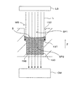
図1は本発明に係る試料容器の一例であるウェルプレートの全体構造を示す図である。より詳しくは、図1(a)はウェルプレート10の上面図であり、また図1(b)はこのウェルプレート10の斜視図である。このウェルプレート10は、例えばプラスチック製のプレート状の基材11に、上面が開口し底面が閉塞された略円筒状(または、底面に向けて水平断面積が漸減するテーパー付きの円錐台形状)のウェルWが一定のピッチで規則的に二次元マトリクス配置された構造を有している。ここでは12×8(=96)箇所のウェルWが設けられたウェルプレート10の例を示しているが、1つのプレートに設けられるウェルの数は任意である。
FIG. 1 is a diagram showing the entire structure of a well plate which is an example of a sample container according to the present invention. More specifically, FIG. 1A is a top view of the
ウェルプレート10はその上面10aが水平となるような姿勢で、各ウェルWの側壁面および底面で囲まれた内部空間に液体を担持可能である。例えば、医学や生化学の分野において、ウェルWに注入された培養液中で細胞等を培養して試料を作製する目的に、このウェルプレート10を好適に適用可能である。図1はウェルプレート10が水平姿勢に保持された状態を表しており、XY面が水平面を、+Z方向が鉛直上向き方向をそれぞれ表している。
The
各ウェルWの底面は、基材11と一体的に形成されていてもよく、また基材11にZ方向(鉛直方向)に設けられた貫通孔の底部を例えば樹脂製のシート体により塞ぐことによりウェル底面が構成されてもよい。培養により作製された試料が顕微鏡観察あるいは顕微撮像等に供されるものである場合には、底面は観察時の照明光に対して透明な材料で構成されることが望ましい。
The bottom surface of each well W may be formed integrally with the
次に、ウェルWの内部構造について説明する。これまで製品化されている一般的なウェルプレートにおける各ウェルの内部空間は、水平断面が円形や矩形等の比較的単純な形状である側壁面と略平坦な底面とで囲まれる空間として規定されている。このため、ウェルを上方から観察したとき、液面の高さを判定することが困難である。特に多数のウェルが二次元配列されたウェルプレートにおいては、各ウェルの液面を横方向から観察することもできない。このため、各ウェルWに担持されている液体の量を推定することが難しい。 Next, the internal structure of the well W will be described. The internal space of each well in a general well plate that has been commercialized so far is defined as a space that is surrounded by a side wall surface that has a relatively simple horizontal shape, such as a circle or rectangle, and a substantially flat bottom surface. ing. For this reason, when the well is observed from above, it is difficult to determine the height of the liquid level. In particular, in a well plate in which a large number of wells are two-dimensionally arranged, the liquid level of each well cannot be observed from the lateral direction. For this reason, it is difficult to estimate the amount of liquid carried in each well W.
例えば細胞等の培養を目的として、ウェルWに培養液が注入されたウェルプレート10が恒温・恒湿のインキュベータ内に置かれる場合、時間の経過とともに培養液の蒸発が進行する。これにより培養液中の成分の濃度が高くなりすぎて培養環境が不適切なものとなる場合があり得る。また、培養された試料が光学的な観察に供される場合、液面が低下することで、液面のメニスカスに起因するレンズ効果が顕著となり、観察に支障が生じることがあり得る。
For example, when the
このような問題を未然に防止するために、各ウェルWに担持されている液体の量を随時評価し必要に応じて液体を補充することが必要となる。しかしながら、上記したように、一般的なウェルプレートでは各ウェルの液面高さを目視により判定することが困難であるため、液量の評価を簡単に行うことができなかった。以下、上方からの目視によりウェルW内の液量を簡単に判定することを可能としたウェルWの内部構造の幾つかの例について説明する。 In order to prevent such a problem in advance, it is necessary to evaluate the amount of liquid carried in each well W as needed and replenish the liquid as necessary. However, as described above, since it is difficult to visually determine the liquid level height of each well in a general well plate, the liquid amount cannot be easily evaluated. Hereinafter, some examples of the internal structure of the well W that makes it possible to easily determine the amount of liquid in the well W visually from above will be described.
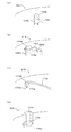
図2は本発明に係る内部構造を有するウェルの第1の例を示す図である。図において(a)欄はウェルの内部構造を模式的に示す透視図であり、内部構造を明瞭に示すために、ウェルの開口、側壁面および底面の周縁に該当する稜線については点線により示している。また(b)欄は液体が注入されていないウェルを上方から見たときの図であり、(c)欄は(a)欄に示す一点鎖線でウェル側壁面を切開したときの展開図である。 FIG. 2 is a view showing a first example of a well having an internal structure according to the present invention. In the figure, column (a) is a perspective view schematically showing the internal structure of the well. In order to clearly show the internal structure, the ridge lines corresponding to the periphery of the well opening, the side wall surface, and the bottom surface are indicated by dotted lines. Yes. Further, (b) column is a view when a well into which no liquid is injected is viewed from above, and (c) column is a developed view when the side wall surface of the well is incised by a dashed line shown in (a) column. .
また、(d)ないし(f)欄は液量の違いによるウェルの見え方の違いを示したものであり、各欄において左の図はウェルを側方から見たときの図、中央の図は液面を断面としたときのウェル内部空間の水平断面図、右の図はウェルを上方から見たときの液面の形状を示す図である。(d)欄は液量が比較的多いケース、(e)欄は(d)欄に示すケースより液量が少ないケース、(f)欄は(e)欄に示すケースよりさらに液量が少ないケースをそれぞれ表している。 Also, columns (d) to (f) show the difference in the appearance of the well due to the difference in the liquid volume. In each column, the left figure is a view when the well is viewed from the side, and the middle figure. Is a horizontal sectional view of the well internal space when the liquid surface is taken as a cross section, and the right figure is a diagram showing the shape of the liquid surface when the well is viewed from above. (D) column has a relatively large liquid volume, (e) column has a smaller liquid volume than the case shown in (d) column, and (f) column has a smaller liquid volume than the case shown in (e) column. Each case is represented.
なお、上記した(a)ないし(f)各欄の内容についての説明は、後出の図3ないし図9のそれぞれにおいても共通である。 The description of the contents of the above-described columns (a) to (f) is the same in each of FIGS. 3 to 9 described later.
図2に示す第1の例のウェルW1は、上部が開口面111となり略円筒形の側壁面112と略平坦な底面113とで囲まれる内部空間SPに液体を貯留可能である。このウェルW1においては、底面113から上方へ、かつ側壁面112に沿って柱状に延設された3つの突出部位114,115,116が設けられている。突出部位114,115,116は側壁面112に接しており、したがって、各突出部位114,115,116は側壁面112からウェル内部空間SPの中央部に向けてリブ状に突出した構造体である。なお各突出部位114,115,116の水平断面形状は、ここでは矩形であるが任意の形状であってよい。
The well W1 of the first example shown in FIG. 2 can store liquid in the internal space SP surrounded by a substantially cylindrical
(b)欄に示すように、ウェルW1を上方から見ると、開口面111の内部に各突出部位114,115,116の頂面と底面113とが現れた状態となっている。(a)欄および(c)欄に示すように、底面113を基準としたときの鉛直方向高さは、突出部位114が最も高く、突出部位115がこれに次ぎ、突出部位116が最も低い。したがって、開口面111から鉛直方向下向きの深さ方向においては、突出部位114の頂面が最も浅い位置にあり、突出部位115の頂面がこれに次ぎ、突出部位116の頂面が最も深い位置にある。
As shown in the column (b), when the well W1 is viewed from above, the top surface and the
このような構造のウェルW1に量が比較的多い液体が注入されており、(d)欄に示すように、突出部位114の頂部が液面Sよりも上方に露出する一方、突出部位115,116の頂部が液面Sよりも下方にある場合を考える。なお、実際には液面はメニスカスを形成するが、(d)ないし(f)欄の左図に示される液面Sはウェル側壁面112と接する部分での高さを表しているため、水平な直線として示されている。このときの液面高さに相当する水平断面におけるウェル内部空間SPの断面図が(d)欄中央の図であり、同図に示されるように、このときの断面は、側壁面112がなす略円形の外周部の一部を突出部位114により切り欠いた形状となっている。
A relatively large amount of liquid is injected into the well W1 having such a structure, and as shown in the column (d), the top of the protruding
また、このときの液面Sを上方から開口面111を介して見ると、(d)欄右図に示すように、略円形の液面Sから突出部位114のみが露出し、他の突出部位115,116は液中に没して隠れた状態となっている。言い換えれば、上方から見た液面Sが(d)欄右図に示す状態であれば、そのときの液量は突出部位114のみが露出するような比較的多いものであるということができる。
Further, when the liquid surface S at this time is viewed from above through the opening
一方、(e)欄に示すように、突出部位114に加えて突出部位115の頂部も液面Sから露出するような液量である場合には、当該液面高さの水平断面における内部空間SPの断面の形状は、(d)欄に示すものとは異なる。具体的には、(e)欄中央の図に示すように、(d)欄中央に示す断面からさらに突出部位115に対応する切り欠きが付加された形状となる。このときの液面を上方から見ると、(e)欄右図に示すように、液面Sから突出部位114,115が露出した状態となる。
On the other hand, as shown in the column (e), when the liquid amount is such that the top of the protruding
さらに液量が少なく、(f)欄左図に示すように3つの突出部位114,115,116の全ての頂部が液面Sから露出した状態では、これに対応して、当該液面高さにおけるウェル内部空間SPの断面形状は、突出部位116に対応する切り欠きがさらに付加された形状となる。また、上から液面Sを見たときの状態も、3つの突出部位114,115,116の全てが液面Sから露出したものとなる。
Further, in the state where the liquid amount is small and all the tops of the three projecting
このように、ウェルW1の側壁面112に底面113からの高さが互いに異なる(つまり開口面111からの深さが互いに異なる)突出部位114,115,116が設けられることによって、液面高さにおけるウェル内部空間SPの断面形状が液量に応じて変化し、これに伴って液面Sを上方から見たときの見え方も変化する。このことを利用して、液面Sを上方から観察することで、ウェルW1内の液量を評価することが可能となる。
Thus, the liquid surface height is obtained by providing the protruding
例えば、突出部位114の高さを、ウェルW1に担持されるべき液体の量の上限値に対応する液面高さに設定し、突出部位116の高さを、ウェルW1に担持されるべき液体の量の下限値に対応する液面高さに設定すれば、次のことがわかるようになる。すなわち、上方から液面を観察したときにいずれの突出部位も露出していなければ液体の量が過剰である。一方、全ての突出部位が露出していれば液体が少なすぎる。少なくとも1つの突出部位が露出し、かつ少なくとも1つの突出部位が液中に隠れた状態が、ウェルW1内の液量が適正な範囲内にある状態を表すことになる。
For example, the height of the protruding
ただし、液量の上限および下限に対応する2つの突出部位を設けただけでは、液量が適正範囲内のどの位置にあるかを把握することができない。このため、突出部位116が液面から露出してしまうまで液量の減少が検知されず、液体の補充の時期を知るという目的は達成されないことになる。
However, it is impossible to grasp where the liquid amount is in the appropriate range simply by providing two projecting portions corresponding to the upper limit and the lower limit of the liquid amount. For this reason, the decrease in the liquid amount is not detected until the protruding
そこで、突出部位114の高さと突出部位116の高さとの間の中間的な高さの突出部位115を設けることで、液量が上限、下限のいずれに近い状態であるかの判断を可能とする。すなわち、上方から液面を見たときに突出部位114のみが露出していれば、少なくとも液面が突出部位115の高さを超える高さとなる程度の液量が確保されている。一方、突出部位114と突出部位115とが露出していれば、液量はより下限に近付いていることが示される。補充の目安となる液量の場合の液面高さに対応する位置に突出部位115の頂部が設けられていれば、突出部位115の露出を確認したことを以って液体の補充が必要であると判断することができる。逆に、突出部位115が露出していなければ、補充は不要であると判断することができる。
Therefore, by providing the protruding
このように、第1の例のウェルW1においては、側壁面112に沿って開口面111からの深さが互いに異なる3つの突出部位114,115,116を設けることにより、液量の変化に伴う液面Sの高さの変化を、上方からの液面Sの観察によって把握することが可能となる。少なくとも2箇所の突出部位を設ければ、液量の上限および下限を示すことが可能である。液量をより多段階に判定することが必要であれば、突出部位の設置数をさらに多くすればよい。液面から露出している突出部位の数によって液量が示されるので、専門知識を必要とせずに判断が可能である。
As described above, in the well W1 of the first example, by providing the three protruding
なお、従来のウェルプレートにおいては、ウェル内部空間の水平断面が底面に近づくにつれて小さくなる、側壁面がいわゆるテーパー形状となったものがある。このような構造のウェルにおいては、上方から液面を見たときの液面の形状は変わらないが、その面積が液面の高さに応じて変化し、このことが液量を判定するための情報となり得る。しかしながら、単なる大きさの変化は目視観察では判定しづらく、何らかの基準との対比が必要となる場合もある。上記例のように、内部空間の水平断面の外周形状が深さに応じて非相似な形状に変化するようにすれば、詳しい知識を持たないユーザーでも容易に液量を評価することが可能となる。突出部位は側壁面112に沿って設けられるので、ウェル中央部での細胞等の培養および観察には影響が少ない。
In some well plates, the side wall surface has a so-called tapered shape that becomes smaller as the horizontal cross section of the well internal space approaches the bottom surface. In the well having such a structure, the shape of the liquid level does not change when the liquid level is viewed from above, but the area changes according to the height of the liquid level, and this is to determine the liquid amount. Information. However, a simple change in size is difficult to determine by visual observation, and may need to be compared with some standard. As in the above example, if the outer peripheral shape of the horizontal cross section of the internal space changes to a non-similar shape according to the depth, it is possible for a user without detailed knowledge to easily evaluate the liquid amount. Become. Since the protruding portion is provided along the
また、液面高さの変化に起因するウェル内部空間の断面形状の変化を上方からの観察により検知可能とするためには、断面形状を表す液面を遮蔽し上方からの視認を阻害するような構造物が液面よりも上方にないことが必要である。このためには、ウェル内部空間SPの任意の深さ位置での一の断面(深さ0の断面、つまり開口面111を含む)が、これより深い位置での任意の断面を平面視において完全に含むように、各部の形状が設定されればよい。 In addition, in order to be able to detect the change in the cross-sectional shape of the well internal space due to the change in the liquid level height by observing from above, the liquid level representing the cross-sectional shape is shielded to obstruct visibility from above. It is necessary that no such structure be above the liquid level. For this purpose, an arbitrary cross section at a position deeper than that of one cross section (including a cross section having a depth of 0, that is, the opening surface 111) at an arbitrary depth position in the well internal space SP is completely seen in a plan view. The shape of each part should just be set so that it may be included.
図2の例では、各突出部位114,115,116を底面113から上向きに延びる断面形状が一定の柱状体としているため、この要件が満たされている。また、この要件が満たされる限りにおいて、各部の形状の変更が許容される。例えば、側壁面112は底面113に近づくほど水平断面が小さくなるテーパー形状を有していてもよい。また例えば、各突出部位114,115,116は上部よりも下部の断面積が大きくなるものであってもよい。
In the example of FIG. 2, each projecting
以下、本発明に係る内部構造を有するウェルの他の幾つかの例を順次説明する。上記の例と後出の各例とでは突出部位の形状が異なり、それに起因して液面に現れる形状変化の態様が相違するが、液面の形状変化で液量を示そうとする基本的な原理は共通である。そこで、各例における構造や機能について上記例と共通する点については詳細な説明を省略し、上記例との相違点を中心に説明することとする。 Hereinafter, several other examples of wells having an internal structure according to the present invention will be sequentially described. The shape of the protruding part is different in the above example and each of the following examples, and the form of the shape change that appears on the liquid level is different due to this, but the basic attempt to indicate the liquid amount by the change in the shape of the liquid level The principle is common. Therefore, detailed description of the points common to the above examples regarding the structure and function in each example will be omitted, and differences from the above examples will be mainly described.
図3は本発明に係る内部構造を有するウェルの第2の例を示す図である。前記の通り、図3各欄の見方は図2と同じである。図3に示す第2の例のウェルW2では、第1の例のウェルW1において側壁面112から内向きに突出してリブ状に設けられた突出部位114,115,116に代えて、ウェルW2の底面123から側壁面122に沿って上向きに突出して設けられた円柱状の突出部位124,125,126を有している。なお突出部位の断面形状は円形に限定されず任意である。また、各突出部位124,125,126はウェルW2の側壁面122に接していてもよく、側壁面122から離間していてもよい。
FIG. 3 is a view showing a second example of a well having an internal structure according to the present invention. As described above, the view of each column in FIG. 3 is the same as FIG. In the well W2 of the second example shown in FIG. 3, instead of the projecting
このような構造のウェルW2を上方から見たとき、(b)欄に示すように、開口面121に対応する円形の領域内に突出部位124,125,126の頂面が含まれた状態となる。また、各突出部位124,125,126がウェルW2の側壁面122から離間した状態であれば、(d)欄ないし(f)欄に示すように、ウェル内部空間SPにおいて液面Sの高さが変化したとしても、液面高さの位置での内部空間SPの断面の外周形状(この場合は円形)は不変である。外周形状の中に含まれる、各突出部位の断面に相当する円形の数が、液面高さによって変化する。
When the well W2 having such a structure is viewed from above, as shown in the column (b), the top surface of the projecting
具体的には、液面Sが比較的高い位置にある(d)欄に示される状態では、頂部が液面Sより高い位置にある突出部位124の断面が、外周形状を表す円の中に含まれる。また、液面Sがより低い位置にある(e)欄に示される状態では、頂部が液面Sより高い位置にある突出部位124,125の断面が、外周形状を表す円の中に含まれる。一方、液面Sが最も低い位置にある(f)欄に示される状態では、全ての突出部位の頂部が液面Sより高い位置にあるため、各突出部位124,125,126の断面が外周形状を表す円の中に含まれる。
Specifically, in the state shown in the column (d) where the liquid level S is at a relatively high position, the cross section of the protruding
このような断面形状の変化に伴って、開口121を介して上方から液面Sを観察したとき、(d)〜(f)欄の右図に示すように、液面から露出する突出部位の数が、液面Sの高さに応じて変化する。したがって、各突出部位124,125,126の頂部の高さを適宜に設定することで、第1の例のウェルW1と同様に、液面Sの目視によって、液量の上限および下限や、補充を必要とするタイミング等を把握するための情報等を得ることが可能となる。前述の従来技術においては、突起部が底面中央部に設けられて細胞の培養に積極的に関与するよう構成されているが、本例では突出部位124等がウェル側壁面122の近傍のみに設けられているため、底面形状は任意であり、例えばほぼ平坦な形状とすれば細胞等の培養およびその観察への影響はない。本発明に係る突出部位と、上記従来技術のような突起部とを組み合わせて実施することも可能である。
With such a change in the cross-sectional shape, when the liquid surface S is observed from above through the
図4は本発明に係る内部構造を有するウェルの第3の例を示す図である。第3の例のウェルW3では、第1の例のウェルW1では側壁面112からウェル内部空間SPの中央部側に向けて突出する突出部位114,115,116に代えて、(a)欄に示すように、側壁面132から外向きに突出する突出部位134,135,136が設けられている。外部空間から見れば、突出部位134,135,136は、側壁面132から後退した面を持つ溝状の凹部であるとも言える。これらの突出部位の水平断面形状は任意である。
FIG. 4 is a view showing a third example of a well having an internal structure according to the present invention. In the well W3 of the third example, in the well W1 of the first example, instead of the protruding
前記したように、一の水平断面におけるウェル内部空間SPの断面が、これより深い位置での断面の全てを含むという要請に基づき、この例では、各突出部位134,135,136は、ウェルプレート上部で開口する開口面131から下向きに延設されている。各突出部位134,135,136の底部の高さ(すなわち開口面131からの深さ)は互いに異なっており、ただし、いずれもウェル底面133の位置よりも浅い位置に底部を有する。これらの底部が、第1の例のウェルW1における各突出部位114,115,116の頂部と同様に機能する。
As described above, based on the request that the cross section of the well internal space SP in one horizontal cross section includes all of the cross sections at deeper positions, in this example, each projecting
すなわち、ウェルW3に液体が入っていない状態では、(b)欄に示すように、開口131を介して上方からウェルW3を観察したときウェル底面133と各突出部位134,135,136の底部とが見えている。一方、例えば(d)欄に示すように、突出部位135,136の底部が液面Sより下方にあり、突出部位134の底部が液面Sより上方にあるような液量のとき、当該液面高さにおけるウェル内部空間SPの断面は、側壁面132に対応する円のうち突出部位135,136に対応する位置が外側に拡張された形状を有する。したがって、開口面131を介して上方から液面Sを観察したとき、突出部位135,136の底部は液中に没し、突出部位134の底部だけが露出した状態となっている。
That is, in a state where no liquid is contained in the well W3, as shown in the column (b), when the well W3 is observed from above through the
(e)欄および(f)欄に示すように、液面Sの高さが変化すると、それに伴ってウェル内部空間SPの断面の外周形状が変化し、上方から観察される液面Sの形状も変化する。すなわち、液量が少なくなるにつれて、突出部位135の底部、突出部位136の底部が順次液面Sから露出するようになる。したがって、第1の例と同様に、上方から観察される各突出部位の露出の状況から、液面Sの高さ、つまり液量に関する情報を得ることが可能である。
As shown in columns (e) and (f), when the height of the liquid level S changes, the outer peripheral shape of the cross section of the well internal space SP changes accordingly, and the shape of the liquid level S observed from above is shown. Also changes. That is, as the liquid amount decreases, the bottom of the protruding
このように、突出部位が側壁面から外向きに設けられた構成においては、液面が下がるほど、当該液面高さの断面に現れる突出部位は少なくなってゆく。ただし、断面に現れなくなった部分の底部は液面Sから露出した状態となっているため、上方からの観察で容易に視認することが可能である。 As described above, in the configuration in which the protruding portion is provided outward from the side wall surface, the protruding portion appearing in the cross section of the liquid surface height decreases as the liquid level decreases. However, since the bottom of the portion that no longer appears in the cross section is exposed from the liquid surface S, it can be easily visually recognized from above.
図5は本発明に係る内部構造を有するウェルの第4の例を示す図である。第4の例のウェルW4では、第1の例において離隔配置されていた、互いに高さの異なる複数の突出部位に代えて、頂部の高さが多段階に変化する単一の突出部位140が、ウェルW4の側壁面142からウェル内部空間SPの中央部側に向けて突出して設けられている。すなわち、突出部位140は、内部空間SPの内部において最も高い位置にある平面部144と、これより低い位置にある平面部145と、さらに低い位置にある平面部146とを含む階段状の上部構造を有している。
FIG. 5 is a view showing a fourth example of a well having an internal structure according to the present invention. In the well W4 of the fourth example, instead of the plurality of protruding portions having different heights that are spaced apart from each other in the first example, a single protruding
このため、上記原理と同様に、液面Sの減少に伴って、突出部位140の各平面部のうち露出する部分が多くなり、これにより、開口面141から液面Sを観察したときの各平面部144,145,146の露出状況が変化する。したがって、第1の例と同様に、上方から観察される各平面部の露出の状況から、液面Sの高さ、つまり液量に関する情報を得ることが可能である。
For this reason, as in the above principle, as the liquid level S decreases, the exposed portions of the flat portions of the projecting
図6は本発明に係る内部構造を有するウェルの第5の例を示す図である。第5の例のウェルW5では、第4の例において高さが順番に変化する階段状に設けられていた平面部の配置に代えて、最も低い平面部155を挟むように最も高い平面部154およびこれに次ぐ高さの平面部156を有する突出部位150が、側壁面152から内向きに突出して設けられる。
FIG. 6 is a view showing a fifth example of a well having an internal structure according to the present invention. In the well W5 of the fifth example, the highest
この例では、(e)欄に示すように、液面Sの高さが中間的な位置にあるときに液面Sから露出する平面部154,156が、開口面151を介した観察において互いに離隔して見えることとなる。そのため、(d)欄および(f)欄に示す状態との識別性という点で、図5に示す第4の例よりも向上する。
In this example, as shown in the column (e), the
第4および第5の例においても、その変形例として、突出部位を側壁面から外向きに突出した構造とすることが可能である。その一例として、第4の例に対応する変形例である第6の例のウェルW6について説明する。 Also in the fourth and fifth examples, as a modification thereof, it is possible to have a structure in which the protruding portion protrudes outward from the side wall surface. As an example, a well W6 of a sixth example which is a modification corresponding to the fourth example will be described.
図7は本発明に係る内部構造を有するウェルの第6の例を示す図である。第6の例のウェルW6では、階段状の底部を有する突出部位160が、側壁面162から外向きに突出して設けられている。すなわち、突出部位160は、最も高い位置にある平面部164と、これに次ぐ高さにある平面部165と、最も低い位置にある底面部166とを含む階段状の下部構造を有している。
FIG. 7 is a view showing a sixth example of a well having an internal structure according to the present invention. In the well W6 of the sixth example, a protruding
この例においても、(d)〜(f)欄に示されるように、液面Sの高さに応じて内部空間SPの断面の外周形状が変化し、これに伴って、開口面161から液面Sを見たときの液面Sの形状および各平面部164,165,166の露出状況が変化する。したがって、上記各例と同様に、上方から観察される各平面部の露出の状況から、液面Sの高さ、つまり液量に関する情報を得ることが可能である。
Also in this example, as shown in the columns (d) to (f), the outer peripheral shape of the cross section of the internal space SP changes according to the height of the liquid surface S, and accordingly, the liquid from the opening
図8は本発明に係る内部構造を有するウェルの第7の例を示す図である。第7の例のウェルW7では、上記第4の例における階段状の上部構造に代えて、上面の高さが連続的に変化する突出部位170が、ウェルW7の側壁面172から内部空間SP中央側に向けて突出して設けられている。具体的には、突出部位170の頂部は小面積の平面部174となっており、平面部174に接続する傾斜面部175が、その後端部176まで高さが連続的に変化する側壁面172に沿った傾斜面、つまり、当該面の法線が鉛直上向きの成分と水平方向成分とを有する面となっている。(c)欄に実線、点線および破線で示すように、後端部176に続く部分の高さ変化は任意である。また、製造上の問題が生じない限りにおいて、平面部174は省略されてもよい。
FIG. 8 is a view showing a seventh example of a well having an internal structure according to the present invention. In the well W7 of the seventh example, instead of the stepped upper structure in the fourth example, the protruding
このような構造を有するウェルW7においては、(d)〜(f)欄に示すように、液面Sの高さに応じて液面Sから露出する傾斜面部175の長さが増加し、これに伴って断面に占める突出部位170に対応する領域の面積が増加する。このため、開口面171を介して液面Sを見たとき、液量の減少に伴って、露出する傾斜面部175の長さが長くなってくる。つまり、液面Sの高さを、露出する傾斜面部175の長さに変換して示すことが可能である。
In the well W7 having such a structure, as shown in the columns (d) to (f), the length of the
液量の上限および下限、また液体の補充タイミングを示す情報をより簡単に得るためには、例えば(f)欄に示すように、開口171の周囲の基材上面に適宜のマーカーMkを印刷、刻設等により予め設けておけばよい。上面からの観察において、液量の低下に伴い延びる傾斜面部175の先端部とマーカーMkとの位置関係に基づき、担持される液体の量を定量的に示すことが可能となる。
In order to more easily obtain information indicating the upper and lower limits of the liquid amount and the timing of liquid replenishment, for example, as shown in the column (f), an appropriate marker Mk is printed on the upper surface of the base material around the
図9は本発明に係る内部構造を有するウェルの第8の例を示す図である。第8の例のウェルW8では、上記第7の例において内向きに突出する突出部位に代えて、底部の高さが連続的に変化する突出部位180が側壁面182から外向きに突出した構造を有している。このような構造でも、第7の例と同様に、液面Sの低下に伴い、突出部位180の傾斜面部185のうち露出する部分が増加し、これに伴い開口面181から見たときの液面Sの形状および突出部位180の露出状況が変化する。
FIG. 9 is a view showing an eighth example of a well having an internal structure according to the present invention. In the well W8 of the eighth example, instead of the projecting part projecting inward in the seventh example, the projecting
具体的には、(d)欄に示すように液面Sが高い位置にあるときには傾斜面部185の上端部184近傍のみが液面Sから上方に露出しているが、液面Sの低下に伴い傾斜面部185の露出部分が増えてくる。上方からの観察では、液面Sの外周部に見える突出部位180が次第に長く延びてくる。傾斜面部185の下端部186の位置は液面Sの形状から把握することができるので、上方からの観察により得られる傾斜面部185の露出部分の先端から下端部186までの距離から、液量が下限にどの程度まで近づいているかを直ちに把握することが可能である。
Specifically, as shown in the column (d), when the liquid level S is at a high position, only the vicinity of the
図10は本発明に係る内部構造を有するウェルの第9の例を示す図である。より具体的には、図10(a)は第9の例のウェルW9の内部構造を示す透視図およびウェルW9の水平断面積の変化を示す図である。また、図10(b)はウェルW9の上面図であり、図10(c)は図10(b)のA−A線断面図である。 FIG. 10 is a diagram showing a ninth example of a well having an internal structure according to the present invention. More specifically, FIG. 10A is a perspective view showing the internal structure of the well W9 of the ninth example and a diagram showing a change in the horizontal sectional area of the well W9. FIG. 10B is a top view of the well W9, and FIG. 10C is a cross-sectional view taken along the line AA in FIG. 10B.
第9の例のウェルW9では、内部空間SPの垂直断面における概略形状が上記各例のものとは相違している。すなわち、この例のウェルW9では、開口面191から底面193に至る側壁面が、比較的大きな水平断面積を有する第1の側壁面192と、より小さな水平断面積を有する第2の側壁面198とが、水平断面積が下方に向けて急激に縮小する縮径部位197を介して連結された構造を有している。
In the well W9 of the ninth example, the schematic shape in the vertical cross section of the internal space SP is different from those of the above examples. That is, in the well W9 of this example, the side wall surface from the opening
図10(a)右図に示すように、ウェル内部空間SPの水平断面積は、縮径部位197の前後で急激に変化している。同図に破線で示すように、側壁面192,193の少なくとも一方が、深さの増加とともに断面積が小さくなるテーパー形状を有していてもよい。この場合には、深さの変化に対する断面積の変化率が、他の深さにおける変化率よりも顕著に大きい部分を縮径部位と考えることができる。
As shown in the right figure of FIG. 10A, the horizontal cross-sectional area of the well internal space SP changes rapidly before and after the reduced
つまり、ウェルW9の内部空間SPは、側壁面192により規定される水平断面積の比較的大きい第1空間SP1と、側壁面198により規定されるより水平断面積の小さい第2空間SP2とが上下方向に連結された構造となっている。その連結部分である縮径部位197において、ウェルW9の側壁面は段差を有している。この意味で、縮径部位197は側壁面の一部としての「段差部」であるとも言える。
That is, the internal space SP of the well W9 is divided into a first space SP1 having a relatively large horizontal sectional area defined by the
そして、縮径部位197よりも上方の側壁面192に、上記した第1の例(図2)における突出部位114,115,116と同様の構造および機能を有する突出部位194,195,196が設けられている。なお、図10(a)右図では、突出部位による断面積の変化は無視できるものとしている。一方、縮径部位197よりも下方では、側壁面198は単純な円筒面をなしている。ただしテーパーが設けられてもよい。
Then, the protruding
図11は段差を有するウェルに担持された液体の撮像を例示する図である。ウェルW9に注入された液体中の試料が撮像に供される場合を考える。なおここでは落射照明と透過撮像との組み合わせの例を説明するが、撮像方法はこれに限定されない。例えば、ウェルW9の上方に光源LSを配置し、光源LSから下向きに照射される照明光LをウェルW9に入射させ、ウェル底面193から下方へ透過してくる光を撮像手段CMにより受光することで、ウェルW9内を撮像することができる。
FIG. 11 is a diagram illustrating imaging of a liquid carried in a well having a step. Consider a case where a sample in a liquid injected into the well W9 is used for imaging. Although an example of a combination of epi-illumination and transmission imaging will be described here, the imaging method is not limited to this. For example, the light source LS is disposed above the well W9, the illumination light L irradiated downward from the light source LS is incident on the well W9, and the light transmitted downward from the well
ここで、ウェルW9に注入された液体の液面Sは、ウェル側壁面に接する部分が盛り上がるメニスカスを形成している。このため、上方から液面Sに入射する光Lのうち、側壁面192に近い領域に入射したものは液面のレンズ効果により外側へ曲げられる。このため、例えば内部空間SPの水平断面積が深さ方向において一定である(あるいは連続的かつ単調な微小変化を有する)従来の一般的なウェルでは、底面の周縁部に十分な照明光が入射せず、得られる画像においても底面の周縁部が暗くなってしまうという問題があった。
Here, the liquid level S of the liquid injected into the well W9 forms a meniscus that rises at the portion in contact with the well side wall surface. For this reason, among the light L incident on the liquid surface S from above, the light incident on the region close to the
一方、上記構造を有するウェルW9においては、メニスカスにより曲げられた光は縮径部位197によって遮蔽されるため、底面193においてはほぼ均一な照明条件を得ることができる。これにより、周縁部まで十分な明るさの画像を撮像することが可能である。
On the other hand, in the well W9 having the above structure, the light bent by the meniscus is shielded by the reduced
このような利点を享受するためには、液体が縮径部位197よりも上方まで注入されている必要がある。そこで、この例のウェルW9では、上記のように上方からの観察により液面Sの高さを把握することを可能とする突出部位が、縮径部位197よりも上方に設けられている。突出部位による液面高さの視覚化をこのような構造のウェルに適用することで、上方からの観察によって適切な量の液体が担持されているかを容易に判断することができ、必要に応じて液体の補充を行うことが可能となる。なお、ここでは段差を有するウェルに、第1の例として説明した突出部位が組み合わされているが、他の例の構造を組み合わせることも可能である。
In order to enjoy such an advantage, it is necessary that the liquid is injected above the reduced
上記した各構造のウェルW(W1〜W9)においては、従来はその断面形状が円形や矩形など比較的単純な形状であったのに対し、断面の輪郭の一部に外側または内側に突出する突出部位が設けられている。これにより、液量によって断面形状が変化するため上方からの目視で液量を把握することが可能である。そして、もし液量が不足していると判断された場合には液体が補充される必要がある。また、細胞等の活動により生成される代謝物を除去するために、定期的に液体の交換が行われる場合もある。以下、このような操作に対し上記各ウェルの構造がどのように作用するかについて説明する。 In the wells W (W1 to W9) having the above-described structures, the cross-sectional shape has conventionally been a relatively simple shape such as a circle or a rectangle, but protrudes outward or inward to part of the cross-sectional outline. A protruding portion is provided. Thereby, since the cross-sectional shape changes depending on the liquid amount, it is possible to grasp the liquid amount visually from above. If it is determined that the amount of liquid is insufficient, the liquid needs to be replenished. Moreover, in order to remove the metabolite produced | generated by activities, such as a cell, liquid replacement | exchange may be performed regularly. Hereinafter, how the structure of each well acts on such an operation will be described.
ウェルへの培養液の注入または交換は、必要な液量や作業内容がウェルごとに異なる可能性があることから、操作者が各ウェル内の液体の状態を確認しながら手作業で行うことになる。具体的には、先端の細いピペット等の注液用器具をウェルの上部からウェル内に挿入し、必要量の液体をウェルに注入する、という作業が必要である。このとき、手作業では器具の先端をウェルに対し素早く正確に位置決めすることが困難である。このため、たとえ熟練者であっても作業に時間を要し、また液体がウェル外へ漏出したり、注入量が正確でなかったりすることがあり得る。 Injecting or exchanging the culture medium to the wells may require different amounts of liquid and work contents for each well, so the operator must manually perform the operation while checking the state of the liquid in each well. Become. Specifically, it is necessary to insert a liquid injection instrument such as a pipette with a thin tip into the well from the top of the well and inject a necessary amount of liquid into the well. At this time, it is difficult to quickly and accurately position the tip of the instrument with respect to the well by manual work. For this reason, even if it is an expert, time is required for an operation | work, a liquid may leak out of a well, and injection volume may be inaccurate.
これに関し、上記各構造のウェルは側壁面に液量把握のための突出部位を有している。このような突出部位は、操作者が器具を位置決めする際の基準としても機能し得る。すなわち、器具を保持する操作者が器具の先端を突出部位に突き当てることで、ウェルに対する器具の先端位置を容易に確定させることができる。これにより、素早く正確な注液作業が可能となる。また培養液の交換に際しても、ウェルから培養液を吸引するためのピペットの先端を任意の突出部位に突き当ててウェル内の古い培養液を吸引することで、一定量の古い培養液をウェル内に残しつつ、所定の液面高さまで素早く培養液を除去することができる。これにより、熟練者でなくても正確な量の培養液を交換することができる。 In this regard, the well of each structure described above has a protruding portion for grasping the liquid amount on the side wall surface. Such a protruding portion can also function as a reference when the operator positions the instrument. That is, the operator holding the instrument can easily determine the position of the tip of the instrument with respect to the well by abutting the tip of the instrument against the protruding portion. Thereby, a quick and accurate liquid injection operation is possible. In addition, when exchanging the culture solution, the pipette tip for aspirating the culture solution from the well is abutted against any protruding part and the old culture solution in the well is aspirated, so that a certain amount of the old culture solution is stored in the well. In addition, the culture solution can be quickly removed to a predetermined liquid level. Thereby, even if it is not an expert, the exact quantity culture solution can be replaced | exchanged.
また、このような作業をより効果的に支援するために、突出部位が以下のように構成されてもよい。なお、以下では幾つかの変形例についてウェルの一部分のみを図示し説明するが、図示および説明が省かれている部分に対しても、同様の考え方を適用して変形することが可能である。 Further, in order to support such work more effectively, the protruding portion may be configured as follows. In the following, only a part of the well is illustrated and described for some modified examples. However, the same concept can be applied to a part that is not shown or described for modification.
図12および図13は突出部位の形状の変形例を示す図である。例えば図2に示されるように突出部位がウェル側壁面から内側に向けて突出した態様のウェルW1においては、ウェルW1の上部から注入される液体が突出部位114,115,116の頂面に付着して突出部位を覆い隠すことがある。そこで、図12(a)に示す変形例のウェルW11では、突出部位114aの上面114bが、側壁面112aからウェル中央部へ向かう方向において下向きの勾配を有する傾斜面となっている。このような構成によれば、液体は突出部位114aの上面114bに留まらず下方へ流下するので、上面114bに液体が残留することが回避される。鉛直方向に対し上面114bがなす角θは、30度ないし60度が好ましく、例えば45度とすることができる。以下の各変形例に記載された角θについても同様である。
12 and 13 are diagrams showing modifications of the shape of the protruding portion. For example, as shown in FIG. 2, in the well W1 in which the protruding portion protrudes inward from the side wall surface of the well, the liquid injected from the upper portion of the well W1 adheres to the top surfaces of the protruding
また、図12(b)に示す変形例のウェルW12では、図12(a)の変形例に対しさらなる変形が加えられている。すなわち、突出部位114aの上面114bと側面114cとが接続する稜線部114dの一部を含むように、外向きに窪んだ凹部114eが設けられる。凹部114eの形状は図示のものに限定されず任意である。
Further, in the well W12 of the modified example shown in FIG. 12B, a further modification is added to the modified example of FIG. That is, the recessed
このような構成では、操作者が保持する管状のピペット先端Pを凹部114eに当接させることで、水平方向へのピペット先端Pの移動が拘束される。これにより、ピペット先端Pを容易に、かつ正確に位置決めすることが可能である。この構造は、図12(c)に示すように、上面が水平に形成されたウェルW1の突出部位114に対しても同様に適用可能である。
In such a configuration, the movement of the pipette tip P in the horizontal direction is restricted by bringing the tubular pipette tip P held by the operator into contact with the
図13(a)、図13(b)および図13(c)は、それぞれ図3に示すウェルW2、図5に示すウェルW4および図8に示すウェルW7に対する変形例を示している。図13(a)に示す変形例のウェルW13では、ウェル底面から上向きに延びる柱状の突出部位124aの上面124bが、側壁面からウェル中央部へ向かう方向において下向きの勾配を有する傾斜面となっている。この場合も、点線で示すように、ピペットを突き当てるための凹部124eが設けられてもよい。
FIGS. 13A, 13B, and 13C show modifications to the well W2 shown in FIG. 3, the well W4 shown in FIG. 5, and the well W7 shown in FIG. 8, respectively. In the well W13 of the modification shown in FIG. 13A, the
図13(b)に示す変形例のウェルW14では、階段状に設けられた突出部位140aの上面144b,145b,146bのそれぞれが、側壁面からウェル中央部へ向かう方向において下向きの勾配を有する傾斜面となっている。この場合にも、ピペットを突き当てるための凹部144eが設けられてもよい。ここでは階段状の上面の1つ144bのみに凹部144eが図示されているが、他の上面145b、146bにも凹部が設けられてもよい。
In the well W14 of the modified example shown in FIG. 13B, each of the
図13(c)に示す変形例のウェルW15では、突出部位170a上端の平面部174bが側壁面からウェル中央部へ向かう方向において下向きの勾配を有する傾斜面となっている。傾斜面部175bについては周方向での勾配を有しているので、側壁面からウェル中央部へ向かう方向、つまり径方向の勾配を設けるか否かについては任意である。この場合にも、ピペットを突き当てるための凹部174eが設けられてもよい。
In the well W15 of the modification shown in FIG. 13C, the
一方、図13(d)に示す変形例は、図4に示すウェルW3に対する変形例である。このウェルW3では、ウェル開口面131から外側に向かって突出する突出部位134自体が、ピペットを突き当てる際の位置基準として機能し得る。そこで、これに対する変形例のウェルW16では、注入された液体が突出部位134aの下面134bに付着するのを防止するために、該下面134bが傾斜面となっている。この場合にも、ピペットを突き当てるための凹部134eがさらに設けられてもよい。
On the other hand, the modification shown in FIG. 13D is a modification to the well W3 shown in FIG. In the well W3, the protruding
ここに変形例を記載していない各ウェルについても、上記と同様の考え方に基づき、突出部位が上面を有するものについてはその上面を、また下面を有するものについてはその下面を傾斜面とすることにより、注入された液体を滞留させることなく下方へ流下させることができる。また、必要に応じて凹部を設けることにより、注液作業の作業性および作業精度を向上させることができる。 For each well not described here, based on the same concept as above, the upper surface of the protruding portion has an upper surface, and the lower surface of the well having a lower surface has an inclined surface. Thus, the injected liquid can be allowed to flow downward without stagnation. Moreover, the workability | operativity and work | work precision of a liquid injection operation | work can be improved by providing a recessed part as needed.
特に培養液の交換を行う場合、ウェルに挿入された器具先端が培養されている細胞等に接触し損傷を与えるおそれがあるが、上記構造により器具先端の位置決めが容易となることで、そのような問題も解消される。 In particular, when exchanging the culture solution, there is a risk that the tip of the instrument inserted into the well may come into contact with the cultured cells, etc., and damage may occur. The problem is solved.
以上説明したように、上記実施形態においては、ウェルプレート10が本発明の「試料容器」として機能している。また、上記各例のうち複数の突出部位が設けられる構成においては、それらの突出部位が一体として本発明の「突出部」として機能する。また、単一の突出部位を有する構成においては、該突出部位が本発明の「突出部」に相当する。
As described above, in the above embodiment, the
また、図2ないし図9に示す各例においては、各図(d)欄に示される液面Sの開口面からの深さを「第1深さ」とすれば、そのときの内部空間SPの断面が本発明の「第1断面」に相当する。そして、(e)欄および(f)欄に示される液面Sの開口面からの深さが、それぞれ第1深さに対する「第2深さ」に相当し、そのときの内部空間SPの断面が本発明の「第2断面」に相当する。一方、各図(e)欄に示される液面Sの開口面からの深さを「第1深さ」とすれば、(f)欄に示される液面Sの開口面からの深さが、第1深さに対する「第2深さ」に相当することになる。 Further, in each example shown in FIGS. 2 to 9, if the depth from the opening surface of the liquid level S shown in each column (d) is “first depth”, the internal space SP at that time The cross section corresponds to the “first cross section” of the present invention. And the depth from the opening surface of the liquid level S shown in the (e) column and the (f) column corresponds to the “second depth” with respect to the first depth, respectively, and the cross section of the internal space SP at that time Corresponds to the “second cross section” of the present invention. On the other hand, if the depth from the opening surface of the liquid level S shown in each figure (e) column is “first depth”, the depth from the opening surface of the liquid level S shown in the column (f) is This corresponds to the “second depth” with respect to the first depth.
なお、本発明は上記した実施形態に限定されるものではなく、その趣旨を逸脱しない限りにおいて上述したもの以外に種々の変更を行うことが可能である。例えば、上記した各例のウェルは概略円形の水平断面を有するものであるが、これに限定されず、例えば矩形断面を有するウェルに対しても、本発明を適用することが可能である。 The present invention is not limited to the above-described embodiment, and various modifications other than those described above can be made without departing from the spirit of the present invention. For example, the wells of the above examples have a substantially circular horizontal cross section, but the present invention is not limited to this, and the present invention can be applied to wells having a rectangular cross section, for example.
また、上記においては突出部位の高さが3段階に異なる例を幾つか示したが、高さの段階は2以上であれば任意である。 Further, in the above, some examples in which the height of the protruding portion is different in three stages have been shown, but the height stage is arbitrary as long as it is two or more.
また、上記各例ではウェルの開口が水平面と一致するが、開口は必ずしも水平である必要はない。この場合、適宜の水平面に投影された開口の形状を開口面の形状とみなし、これより深い位置での各断面が、平面視において開口面の内部に含まれるようなウェルの構造が実現されればよい。 In each of the above examples, the opening of the well coincides with the horizontal plane, but the opening does not necessarily have to be horizontal. In this case, a well structure is realized in which the shape of the opening projected on an appropriate horizontal plane is regarded as the shape of the opening surface, and each cross section at a deeper position is included in the opening surface in plan view. That's fine.
また、上記のウェルプレート10は、それぞれが液体を貯留可能な複数のウェルWを有するものであるが、本発明の「試料容器」はこのような形態のものに限定されない。例えば、液体を貯留する貯留空間を1つだけ有する「ディッシュ」や「シャーレ」等と称される試料容器においても、本発明を適用することが可能である。
The
以上、具体的な実施形態を例示して説明してきたように、この発明に係る試料容器は、例えば、ウェルの側壁面から内部空間の中央部側に向けて突出する突出部が設けられ、突出部は、第1断面に現れ第2断面に現れない部位と、第1断面および第2断面の両方に現れる部位とを含む構成とすることができる。あるいは例えば、ウェルの側壁面の一部が、内部空間から外側に向かう方向に突出する突出部となっており、突出部は、第1断面に現れ第2断面に現れない部位と、第1断面および第2断面の両方に現れる部位とを含む構成とすることができる。 As described above, the sample container according to the present invention is provided with, for example, a protruding portion that protrudes from the side wall surface of the well toward the central portion side of the internal space, as described in the specific embodiment. The portion may include a portion that appears in the first cross section and does not appear in the second cross section, and a portion that appears in both the first cross section and the second cross section. Alternatively, for example, a part of the side wall surface of the well is a protruding portion that protrudes outward from the internal space, and the protruding portion appears in the first cross section and does not appear in the second cross section. And a portion that appears in both of the second cross sections.
このような構成によれば、液面に現れる突出部の数や形状が液量によって変化する。すなわち、ウェル内の液体の量を、上から見たときに液面に現れる突出部の数や形状によって視覚的に示すことが可能である。 According to such a configuration, the number and shape of the protruding portions appearing on the liquid surface change depending on the liquid amount. That is, the amount of liquid in the well can be visually indicated by the number and shape of protrusions appearing on the liquid surface when viewed from above.
これらの場合において、突出部は、鉛直方向の高さが互いに異なりそれぞれが内部空間に臨む複数の頂部を有する構成とすることができる。より具体的には、例えば、突出部は側壁面に沿って鉛直方向に延設された複数の柱状部位を有し、各々の柱状部位の上面が頂部をなす構成とすることができる。このような構成によれば、液面より上方に頂面を有する柱状部位は上方から見たときに液面から露出して見える一方、液面より下方に頂面を有する柱状部位は液中に没した状態となる。そのため、このような見え方の違いから液量を判定することが可能である。 In these cases, the projecting portion may have a plurality of top portions that are different in height in the vertical direction and each face the internal space. More specifically, for example, the protrusion may have a plurality of columnar portions extending in the vertical direction along the side wall surface, and the upper surface of each columnar portion may be a top portion. According to such a configuration, the columnar portion having the top surface above the liquid surface appears to be exposed from the liquid surface when viewed from above, while the columnar portion having the top surface below the liquid surface is in the liquid. It will be in a dead state. Therefore, it is possible to determine the liquid amount from such a difference in appearance.
また例えば、突出部は、面の法線が鉛直方向上向きの成分を有し鉛直方向の高さが水平方向に連続的に変化する上面を有する構成、鉛直方向の高さが互いに異なりそれぞれが内部空間に臨む複数の底部を有する構成、側壁面に沿って鉛直方向に延設された複数の溝部位を有し各々の溝部位の上面が底部をなす構成、面の法線が鉛直方向上向きの成分を有し、鉛直方向の高さが水平方向に連続的に変化する下面を有する構成、のいずれかとすることができる。これらの構成のいずれにおいても、液量の違いに起因する液面高さの違いにより、上方から液面を見たときの形状が液量によって異なる。このため、液面の形状から液量を容易に視認することが可能である。 In addition, for example, the protrusion has a top surface in which the normal of the surface has an upward component in the vertical direction and the vertical height continuously changes in the horizontal direction. A configuration having a plurality of bottom portions facing the space, a configuration having a plurality of groove portions extending in the vertical direction along the side wall surface, and a top surface of each groove portion forming a bottom portion, and a normal of the surface is vertically upward It can be either of the composition which has a lower surface which has a component and the height of a perpendicular direction changes continuously in a horizontal direction. In any of these configurations, the shape when the liquid surface is viewed from above varies depending on the liquid amount due to the difference in liquid surface height caused by the difference in liquid amount. For this reason, it is possible to easily recognize the liquid amount from the shape of the liquid surface.
上記各構成においては、さらに例えば、鉛直方向における一の深さの位置での内部空間の水平断面が、当該深さよりも深い任意の位置での内部空間の水平断面を平面視において含む構成とすることができる。このような構成によれば、液量が少ないときの液面の形状は、より液量が多く液面が高いときの液面の形状を部分的に切り欠いたものとなり、しかもその形状を遮蔽するような構造が液面より上方には存在しない。このため、上方からの観察により液面の形状を的確に把握することが可能である。 In each of the above configurations, for example, the horizontal cross section of the internal space at a position of one depth in the vertical direction includes a horizontal cross section of the internal space at an arbitrary position deeper than the depth in plan view. be able to. According to such a configuration, the shape of the liquid level when the amount of liquid is small is a part of the shape of the liquid level when the amount of liquid is high and the liquid level is high, and the shape is shielded. Such a structure does not exist above the liquid level. For this reason, it is possible to grasp | ascertain the shape of a liquid level exactly by observation from upper direction.
また例えば、側壁面は、鉛直方向の所定高さの位置で、該高さより上の位置に対して該高さより下の位置で内部空間の水平断面積が減少する段差部を形成しており、第2断面は段差部よりも上方の水平断面である構成とすることができる。本願発明者の知見によれば、このような段差部を有するウェルでは、ウェル内を撮像したときに液面のメニスカスによりウェル底面周縁部が暗くなるという現象を抑制することができ、この効果は液面が段差部より上方にあることで得られるものである。そこで、液面が段差部より下方に低下する前にそれを検知することができれば、上記効果を確実に得ることが可能となる。 Further, for example, the side wall surface forms a step portion in which the horizontal cross-sectional area of the internal space decreases at a position below the height at a position at a predetermined height in the vertical direction at a position below the height, A 2nd cross section can be set as the structure which is a horizontal cross section above a level | step-difference part. According to the knowledge of the inventor of the present application, in a well having such a stepped portion, when the inside of the well is imaged, the phenomenon that the peripheral surface of the well bottom becomes dark due to the meniscus of the liquid surface can be suppressed. The liquid level is obtained above the stepped portion. Therefore, if the liquid level can be detected before it falls below the stepped portion, the above effect can be obtained with certainty.
また例えば、第2断面が内部空間に貯留される液体の液面高さの下限に対応する構成とすることができる。このような構成によれば、液面の形状変化により、液量が下限値を上回っているか下回っているかを判断することが可能であり、例えば必要に応じて液体を補充するといった措置を取ることが可能となる。 Further, for example, the second cross section can be configured to correspond to the lower limit of the liquid level height of the liquid stored in the internal space. According to such a configuration, it is possible to determine whether the amount of liquid is above or below the lower limit value due to a change in the shape of the liquid level, for example, taking measures such as replenishing the liquid as necessary. Is possible.
また例えば、突出部が上面を有するものであればその上面が、また下面を有するものであればその下面が、側壁面から内部空間の中央側に向かって下向きに傾斜する傾斜面であってもよい。また例えば突出部の上面と側面との接続部分において一部が外向きに窪んだ凹部を有してもよい。これらの構成によれば、操作者が注液用の器具を用いてウェルに液体を注入する際の作業性および作業精度を向上させることができる。 Further, for example, if the protrusion has an upper surface, the upper surface thereof, and if the protrusion has a lower surface, the lower surface thereof may be an inclined surface inclined downward from the side wall surface toward the center side of the internal space. Good. For example, you may have the recessed part which one part recessed outward in the connection part of the upper surface and side surface of a protrusion part. According to these configurations, it is possible to improve workability and work accuracy when an operator injects a liquid into a well by using an injection device.
この発明は、細胞等の培養対象物を液体とともに保持する試料容器全般に適用することができる。特に、培養により作製された試料を撮像に供する目的に好適である。このような試料容器は、医学・生化学・創薬等の分野において好適に適用することができるものである。 The present invention can be applied to all sample containers for holding a culture object such as a cell together with a liquid. In particular, it is suitable for the purpose of subjecting a sample prepared by culture to imaging. Such a sample container can be suitably applied in fields such as medicine, biochemistry, and drug discovery.
10 ウェルプレート(試料容器)
11 基材
111 (ウェルW1の)開口面
112 (ウェルW1の)側壁面
113 (ウェルW1の)底面
114,115,116 (ウェルW1の)突出部位
124,125,126 (ウェルW2の)柱状部位
134,135,136 (ウェルW3の)溝部位
197 段差部
S 液面
SP 内部空間
W、W1〜W9 ウェル
10 well plate (sample container)
11
Claims (17)
水平姿勢の前記試料容器において、水平面に投影された前記内部空間の開口を開口面、前記開口から鉛直下向きに所定の第1深さの位置での前記内部空間の水平断面を第1断面、前記第1深さよりも深い第2深さの位置での前記内部空間の水平断面を第2断面とするとき、
前記開口面、前記第1断面および前記第2断面の外周の形状が互いに非相似であり、
平面視において、前記第2断面が前記第1断面内に含まれ、前記第1断面が前記開口面内に含まれる、試料容器。 A sample container having a well capable of storing a liquid in an internal space having an upper opening;
In the sample container in a horizontal posture, the opening of the internal space projected on a horizontal plane is an opening surface, and a horizontal cross section of the internal space at a predetermined first depth vertically downward from the opening is a first cross section. When the horizontal cross section of the internal space at the position of the second depth deeper than the first depth is the second cross section,
The shapes of the outer surfaces of the opening surface, the first cross section, and the second cross section are dissimilar to each other,
In the plan view, the second cross section is included in the first cross section, and the first cross section is included in the opening surface.
前記ウェルの底部から前記ウェルの側壁面に沿って上向きに突出する突出部が設けられ、
水平姿勢の前記試料容器において、前記内部空間の開口から鉛直下向きに所定の第1深さの位置での前記内部空間の水平断面を第1断面、前記第1深さよりも深い第2深さの位置での前記内部空間の水平断面を第2断面とするとき、
平面視において、前記第2断面が前記第1断面内に含まれ、
前記突出部は、前記第1断面に現れ前記第2断面に現れない部位と、前記第1断面および前記第2断面の両方に現れる部位とを含む、試料容器。 A sample container having a well capable of storing a liquid in an internal space having an upper opening;
Protrusions projecting upward along the side wall surface of the well from the bottom of the well are provided,
In the sample container in a horizontal posture, a horizontal cross section of the internal space at a position of a predetermined first depth vertically downward from the opening of the internal space has a first cross section and a second depth deeper than the first depth. When the horizontal cross section of the internal space at the position is the second cross section,
In plan view, the second cross section is included in the first cross section,
The protrusion includes a portion that appears in the first cross section and does not appear in the second cross section, and a portion that appears in both the first cross section and the second cross section.
Priority Applications (6)
| Application Number | Priority Date | Filing Date | Title |
|---|---|---|---|
| TW107117669A TWI667343B (en) | 2017-07-05 | 2018-05-24 | Specimen container |
| TW108120901A TWI689583B (en) | 2017-07-05 | 2018-05-24 | Specimen container |
| KR1020180070835A KR102088102B1 (en) | 2017-07-05 | 2018-06-20 | Specimen container |
| EP18179214.4A EP3425038B1 (en) | 2017-07-05 | 2018-06-22 | Specimen container |
| US16/024,667 US11060054B2 (en) | 2017-07-05 | 2018-06-29 | Specimen container |
| CN201810721382.5A CN109207362B (en) | 2017-07-05 | 2018-07-03 | Sample container |
Applications Claiming Priority (4)
| Application Number | Priority Date | Filing Date | Title |
|---|---|---|---|
| JP2017131651 | 2017-07-05 | ||
| JP2017131651 | 2017-07-05 | ||
| JP2017183180 | 2017-09-25 | ||
| JP2017183180 | 2017-09-25 |
Publications (2)
| Publication Number | Publication Date |
|---|---|
| JP2019050798A true JP2019050798A (en) | 2019-04-04 |
| JP2019050798A5 JP2019050798A5 (en) | 2019-08-15 |
Family
ID=66012459
Family Applications (1)
| Application Number | Title | Priority Date | Filing Date |
|---|---|---|---|
| JP2018086223A Pending JP2019050798A (en) | 2017-07-05 | 2018-04-27 | Sample container |
Country Status (2)
| Country | Link |
|---|---|
| JP (1) | JP2019050798A (en) |
| TW (2) | TWI667343B (en) |
Families Citing this family (1)
| Publication number | Priority date | Publication date | Assignee | Title |
|---|---|---|---|---|
| CN110529355B (en) * | 2019-09-09 | 2021-05-28 | 英华达(上海)科技有限公司 | Liquid amount control device and liquid amount control method using same |
Citations (6)
| Publication number | Priority date | Publication date | Assignee | Title |
|---|---|---|---|---|
| US20100028935A1 (en) * | 2006-11-23 | 2010-02-04 | Carlo Ciaiolo | Convex bottom microwell |
| JP2010110262A (en) * | 2008-11-06 | 2010-05-20 | Hitachi Maxell Ltd | Method for amplifying nucleic acid by using well plate |
| JP2010200748A (en) * | 2009-02-09 | 2010-09-16 | Dainippon Printing Co Ltd | Cell culture dish |
| JP2015195762A (en) * | 2014-04-01 | 2015-11-09 | 大日本印刷株式会社 | cell culture vessel |
| JP2016520307A (en) * | 2013-04-30 | 2016-07-14 | コーニング インコーポレイテッド | Spheroid cell culture well product and method thereof |
| WO2017001680A1 (en) * | 2015-07-01 | 2017-01-05 | Insphero Ag | Device for propagating microtissues |
Family Cites Families (2)
| Publication number | Priority date | Publication date | Assignee | Title |
|---|---|---|---|---|
| TW201219776A (en) * | 2010-06-17 | 2012-05-16 | Geneasys Pty Ltd | Microfluidic device with conductivity sensor |
| EP2929014A4 (en) * | 2012-12-07 | 2016-08-03 | Univ Toronto | Cardiac tissue constructs and methods of fabrication thereof |
-
2018
- 2018-04-27 JP JP2018086223A patent/JP2019050798A/en active Pending
- 2018-05-24 TW TW107117669A patent/TWI667343B/en active
- 2018-05-24 TW TW108120901A patent/TWI689583B/en active
Patent Citations (6)
| Publication number | Priority date | Publication date | Assignee | Title |
|---|---|---|---|---|
| US20100028935A1 (en) * | 2006-11-23 | 2010-02-04 | Carlo Ciaiolo | Convex bottom microwell |
| JP2010110262A (en) * | 2008-11-06 | 2010-05-20 | Hitachi Maxell Ltd | Method for amplifying nucleic acid by using well plate |
| JP2010200748A (en) * | 2009-02-09 | 2010-09-16 | Dainippon Printing Co Ltd | Cell culture dish |
| JP2016520307A (en) * | 2013-04-30 | 2016-07-14 | コーニング インコーポレイテッド | Spheroid cell culture well product and method thereof |
| JP2015195762A (en) * | 2014-04-01 | 2015-11-09 | 大日本印刷株式会社 | cell culture vessel |
| WO2017001680A1 (en) * | 2015-07-01 | 2017-01-05 | Insphero Ag | Device for propagating microtissues |
Also Published As
| Publication number | Publication date |
|---|---|
| TWI667343B (en) | 2019-08-01 |
| TW201936917A (en) | 2019-09-16 |
| TW201907000A (en) | 2019-02-16 |
| TWI689583B (en) | 2020-04-01 |
Similar Documents
| Publication | Publication Date | Title |
|---|---|---|
| US9588104B2 (en) | Device, a system and a method for monitoring and/or culturing of microscopic objects | |
| EP3148700B1 (en) | Single column microplate system and carrier for analysis of biological samples | |
| JP5501141B2 (en) | Preparation for liquid sample inspection | |
| JP5768174B1 (en) | Culture vessel | |
| ES2504241T3 (en) | Cover for a counting chamber, viability determination, analysis and manipulation | |
| JP2007185110A (en) | Cell culture vessel | |
| JP2006280298A (en) | Container for cell culture | |
| KR20070040339A (en) | Feces collection container | |
| JP2014002046A (en) | Preparation for inspection of liquid sample | |
| JP5478456B2 (en) | Preparation for liquid sample inspection | |
| JP6123963B1 (en) | Cell processing container | |
| JP3762862B2 (en) | Cell culture vessel | |
| CN105378051A (en) | Structure for culturing cells | |
| JP2019050798A (en) | Sample container | |
| KR102088102B1 (en) | Specimen container | |
| WO2018150689A1 (en) | Cell culture vessel, sample cell for observation, and cell culture method | |
| JP6277639B2 (en) | Culture vessel | |
| CN202281775U (en) | 96-aperture deep orifice plate structure for biology research | |
| JP2020079759A (en) | Tray for storing cassette for medical examination and method of printing examination information on cassette for medical examination using the same | |
| US20230392104A1 (en) | Cell Culture Carrier | |
| JP5959268B2 (en) | Specimen holder and inverted microscope system | |
| CN208151394U (en) | Supplementary reproduction positioning ware | |
| WO2020054743A1 (en) | Multiwell plate for model organisms | |
| JP2006113080A (en) | Cassette for checking pathological tissue | |
| BG66943B1 (en) | Tub for intracytoplasmic injection |
Legal Events
| Date | Code | Title | Description |
|---|---|---|---|
| A521 | Request for written amendment filed |
Free format text: JAPANESE INTERMEDIATE CODE: A523 Effective date: 20190704 |
|
| A621 | Written request for application examination |
Free format text: JAPANESE INTERMEDIATE CODE: A621 Effective date: 20201218 |
|
| A131 | Notification of reasons for refusal |
Free format text: JAPANESE INTERMEDIATE CODE: A131 Effective date: 20220125 |
|
| A521 | Request for written amendment filed |
Free format text: JAPANESE INTERMEDIATE CODE: A523 Effective date: 20220324 |
|
| A02 | Decision of refusal |
Free format text: JAPANESE INTERMEDIATE CODE: A02 Effective date: 20220621 |