EP3556844B1 - Culture instrument - Google Patents
Culture instrument Download PDFInfo
- Publication number
- EP3556844B1 EP3556844B1 EP16924151.0A EP16924151A EP3556844B1 EP 3556844 B1 EP3556844 B1 EP 3556844B1 EP 16924151 A EP16924151 A EP 16924151A EP 3556844 B1 EP3556844 B1 EP 3556844B1
- Authority
- EP
- European Patent Office
- Prior art keywords
- component
- vessel
- lid
- microplate
- vessels
- Prior art date
- Legal status (The legal status is an assumption and is not a legal conclusion. Google has not performed a legal analysis and makes no representation as to the accuracy of the status listed.)
- Active
Links
Images


Classifications
-
- G—PHYSICS
- G01—MEASURING; TESTING
- G01N—INVESTIGATING OR ANALYSING MATERIALS BY DETERMINING THEIR CHEMICAL OR PHYSICAL PROPERTIES
- G01N21/00—Investigating or analysing materials by the use of optical means, i.e. using sub-millimetre waves, infrared, visible or ultraviolet light
- G01N21/75—Systems in which material is subjected to a chemical reaction, the progress or the result of the reaction being investigated
- G01N21/77—Systems in which material is subjected to a chemical reaction, the progress or the result of the reaction being investigated by observing the effect on a chemical indicator
- G01N21/78—Systems in which material is subjected to a chemical reaction, the progress or the result of the reaction being investigated by observing the effect on a chemical indicator producing a change of colour
-
- C—CHEMISTRY; METALLURGY
- C12—BIOCHEMISTRY; BEER; SPIRITS; WINE; VINEGAR; MICROBIOLOGY; ENZYMOLOGY; MUTATION OR GENETIC ENGINEERING
- C12M—APPARATUS FOR ENZYMOLOGY OR MICROBIOLOGY; APPARATUS FOR CULTURING MICROORGANISMS FOR PRODUCING BIOMASS, FOR GROWING CELLS OR FOR OBTAINING FERMENTATION OR METABOLIC PRODUCTS, i.e. BIOREACTORS OR FERMENTERS
- C12M23/00—Constructional details, e.g. recesses, hinges
- C12M23/02—Form or structure of the vessel
- C12M23/12—Well or multiwell plates
-
- B—PERFORMING OPERATIONS; TRANSPORTING
- B01—PHYSICAL OR CHEMICAL PROCESSES OR APPARATUS IN GENERAL
- B01L—CHEMICAL OR PHYSICAL LABORATORY APPARATUS FOR GENERAL USE
- B01L3/00—Containers or dishes for laboratory use, e.g. laboratory glassware; Droppers
- B01L3/50—Containers for the purpose of retaining a material to be analysed, e.g. test tubes
- B01L3/508—Rigid containers without fluid transport within
- B01L3/5085—Rigid containers without fluid transport within for multiple samples, e.g. microtitration plates
- B01L3/50853—Rigid containers without fluid transport within for multiple samples, e.g. microtitration plates with covers or lids
-
- C—CHEMISTRY; METALLURGY
- C12—BIOCHEMISTRY; BEER; SPIRITS; WINE; VINEGAR; MICROBIOLOGY; ENZYMOLOGY; MUTATION OR GENETIC ENGINEERING
- C12M—APPARATUS FOR ENZYMOLOGY OR MICROBIOLOGY; APPARATUS FOR CULTURING MICROORGANISMS FOR PRODUCING BIOMASS, FOR GROWING CELLS OR FOR OBTAINING FERMENTATION OR METABOLIC PRODUCTS, i.e. BIOREACTORS OR FERMENTERS
- C12M1/00—Apparatus for enzymology or microbiology
- C12M1/34—Measuring or testing with condition measuring or sensing means, e.g. colony counters
-
- C—CHEMISTRY; METALLURGY
- C12—BIOCHEMISTRY; BEER; SPIRITS; WINE; VINEGAR; MICROBIOLOGY; ENZYMOLOGY; MUTATION OR GENETIC ENGINEERING
- C12M—APPARATUS FOR ENZYMOLOGY OR MICROBIOLOGY; APPARATUS FOR CULTURING MICROORGANISMS FOR PRODUCING BIOMASS, FOR GROWING CELLS OR FOR OBTAINING FERMENTATION OR METABOLIC PRODUCTS, i.e. BIOREACTORS OR FERMENTERS
- C12M23/00—Constructional details, e.g. recesses, hinges
- C12M23/22—Transparent or translucent parts
-
- C—CHEMISTRY; METALLURGY
- C12—BIOCHEMISTRY; BEER; SPIRITS; WINE; VINEGAR; MICROBIOLOGY; ENZYMOLOGY; MUTATION OR GENETIC ENGINEERING
- C12M—APPARATUS FOR ENZYMOLOGY OR MICROBIOLOGY; APPARATUS FOR CULTURING MICROORGANISMS FOR PRODUCING BIOMASS, FOR GROWING CELLS OR FOR OBTAINING FERMENTATION OR METABOLIC PRODUCTS, i.e. BIOREACTORS OR FERMENTERS
- C12M23/00—Constructional details, e.g. recesses, hinges
- C12M23/34—Internal compartments or partitions
-
- C—CHEMISTRY; METALLURGY
- C12—BIOCHEMISTRY; BEER; SPIRITS; WINE; VINEGAR; MICROBIOLOGY; ENZYMOLOGY; MUTATION OR GENETIC ENGINEERING
- C12M—APPARATUS FOR ENZYMOLOGY OR MICROBIOLOGY; APPARATUS FOR CULTURING MICROORGANISMS FOR PRODUCING BIOMASS, FOR GROWING CELLS OR FOR OBTAINING FERMENTATION OR METABOLIC PRODUCTS, i.e. BIOREACTORS OR FERMENTERS
- C12M23/00—Constructional details, e.g. recesses, hinges
- C12M23/38—Caps; Covers; Plugs; Pouring means
-
- C—CHEMISTRY; METALLURGY
- C12—BIOCHEMISTRY; BEER; SPIRITS; WINE; VINEGAR; MICROBIOLOGY; ENZYMOLOGY; MUTATION OR GENETIC ENGINEERING
- C12M—APPARATUS FOR ENZYMOLOGY OR MICROBIOLOGY; APPARATUS FOR CULTURING MICROORGANISMS FOR PRODUCING BIOMASS, FOR GROWING CELLS OR FOR OBTAINING FERMENTATION OR METABOLIC PRODUCTS, i.e. BIOREACTORS OR FERMENTERS
- C12M37/00—Means for sterilizing, maintaining sterile conditions or avoiding chemical or biological contamination
-
- C—CHEMISTRY; METALLURGY
- C12—BIOCHEMISTRY; BEER; SPIRITS; WINE; VINEGAR; MICROBIOLOGY; ENZYMOLOGY; MUTATION OR GENETIC ENGINEERING
- C12M—APPARATUS FOR ENZYMOLOGY OR MICROBIOLOGY; APPARATUS FOR CULTURING MICROORGANISMS FOR PRODUCING BIOMASS, FOR GROWING CELLS OR FOR OBTAINING FERMENTATION OR METABOLIC PRODUCTS, i.e. BIOREACTORS OR FERMENTERS
- C12M41/00—Means for regulation, monitoring, measurement or control, e.g. flow regulation
- C12M41/30—Means for regulation, monitoring, measurement or control, e.g. flow regulation of concentration
- C12M41/36—Means for regulation, monitoring, measurement or control, e.g. flow regulation of concentration of biomass, e.g. colony counters or by turbidity measurements
-
- G—PHYSICS
- G01—MEASURING; TESTING
- G01N—INVESTIGATING OR ANALYSING MATERIALS BY DETERMINING THEIR CHEMICAL OR PHYSICAL PROPERTIES
- G01N21/00—Investigating or analysing materials by the use of optical means, i.e. using sub-millimetre waves, infrared, visible or ultraviolet light
- G01N21/17—Systems in which incident light is modified in accordance with the properties of the material investigated
- G01N21/25—Colour; Spectral properties, i.e. comparison of effect of material on the light at two or more different wavelengths or wavelength bands
- G01N21/251—Colorimeters; Construction thereof
- G01N21/253—Colorimeters; Construction thereof for batch operation, i.e. multisample apparatus
-
- G—PHYSICS
- G01—MEASURING; TESTING
- G01N—INVESTIGATING OR ANALYSING MATERIALS BY DETERMINING THEIR CHEMICAL OR PHYSICAL PROPERTIES
- G01N21/00—Investigating or analysing materials by the use of optical means, i.e. using sub-millimetre waves, infrared, visible or ultraviolet light
- G01N21/75—Systems in which material is subjected to a chemical reaction, the progress or the result of the reaction being investigated
- G01N21/77—Systems in which material is subjected to a chemical reaction, the progress or the result of the reaction being investigated by observing the effect on a chemical indicator
- G01N21/82—Systems in which material is subjected to a chemical reaction, the progress or the result of the reaction being investigated by observing the effect on a chemical indicator producing a precipitate or turbidity
-
- B—PERFORMING OPERATIONS; TRANSPORTING
- B01—PHYSICAL OR CHEMICAL PROCESSES OR APPARATUS IN GENERAL
- B01L—CHEMICAL OR PHYSICAL LABORATORY APPARATUS FOR GENERAL USE
- B01L2300/00—Additional constructional details
- B01L2300/04—Closures and closing means
- B01L2300/041—Connecting closures to device or container
- B01L2300/042—Caps; Plugs
-
- B—PERFORMING OPERATIONS; TRANSPORTING
- B01—PHYSICAL OR CHEMICAL PROCESSES OR APPARATUS IN GENERAL
- B01L—CHEMICAL OR PHYSICAL LABORATORY APPARATUS FOR GENERAL USE
- B01L2300/00—Additional constructional details
- B01L2300/06—Auxiliary integrated devices, integrated components
-
- B—PERFORMING OPERATIONS; TRANSPORTING
- B01—PHYSICAL OR CHEMICAL PROCESSES OR APPARATUS IN GENERAL
- B01L—CHEMICAL OR PHYSICAL LABORATORY APPARATUS FOR GENERAL USE
- B01L2300/00—Additional constructional details
- B01L2300/08—Geometry, shape and general structure
- B01L2300/0848—Specific forms of parts of containers
-
- G—PHYSICS
- G01—MEASURING; TESTING
- G01N—INVESTIGATING OR ANALYSING MATERIALS BY DETERMINING THEIR CHEMICAL OR PHYSICAL PROPERTIES
- G01N21/00—Investigating or analysing materials by the use of optical means, i.e. using sub-millimetre waves, infrared, visible or ultraviolet light
- G01N21/75—Systems in which material is subjected to a chemical reaction, the progress or the result of the reaction being investigated
- G01N21/77—Systems in which material is subjected to a chemical reaction, the progress or the result of the reaction being investigated by observing the effect on a chemical indicator
- G01N21/78—Systems in which material is subjected to a chemical reaction, the progress or the result of the reaction being investigated by observing the effect on a chemical indicator producing a change of colour
- G01N21/80—Indicating pH value
Definitions
- This invention relates to a culturing device used for examining bacteria, fungi, and the like.
- a culture medium and cells are introduced into a culture vessel to culture the cells.
- a lid is disposed on the culture vessel for the purpose of the prevention of the infection of the cells with bacteria, the inhibition of the increase in the pH of the culture medium, and the like.
- the observation of the change in the form with time, the motility, the invasive ability, and the like of the culture cells is often performed while the lid is disposed on the culture vessel.
- Patent Literature 1 discloses a cell incubator for microscope including a culture dish and a lid provided in its center portion with a recessed portion.
- Patent Literature 1 when the cell culture vessel for microscope according to Patent Literature 1 is applied to the well of the microplate, there is a possibility that, into the well, the culture medium from the adjacent well having different culture conditions is mixed at the time of performing the operation of removing the lid. On the other hand, when the opening is simply provided in the lid to eliminate the operation of removing the lid, the infection with bacteria cannot be prevented.
- This disclosure has been made in view of the above points, and provides a culturing device where an interior of each of culture vessels can be observed with high accuracy and that can reduce a risk of contamination.
- This disclosure includes a plurality of means for solving the above problems, and as an example, provides a culturing device including a microplate having a plurality of vessels, each of the vessels having a bottom surface having light transmittance and having an opening at an upper portion, a lid having light transmittance and covering an upper surface of the microplate, and an intermediate plate having light transmittance and being sandwiched between the lid and the microplate, the intermediate plate having a plurality of convex portions on a surface of the intermediate plate facing the microplate, provided with a plurality of through holes corresponding to the plurality of convex portions.
- the plurality of convex portions and the plurality of through holes are disposed so that when the intermediate plate and the microplate are overlapped, each of the plurality of convex portions is inserted into each of the plurality of vessels and each of the plurality of through holes coincides with the opening of each of the plurality of vessels.
- the lid comes into contact with the intermediate plate so as to close the plurality of through holes provided in the intermediate plate.
- the present invention provides a culturing device as defined in claim 1. It includes a microplate including a plurality of vessels, each of the plurality of vessels having a bottom surface having light transmittance and a component attached into the vessel, the component extending from an upper end of the vessel to an interior of the vessel so as to have an opening and having light transmittance, and a lid having light transmittance and covering an upper surface of the microplate.
- the component has two surfaces substantially parallel to the bottom surface of the vessel, one of the two faces being located at the same height as the upper surface of the microplate or at a position higher than the upper surface of the microplate.
- a lid When cells are cultured by using a culturing device, a lid is typically disposed so as to close an opening of each of vessels in order to prevent the intrusion of bacteria and the like. Since the cells are cultured at temperatures of approximately 30°C to 35°C, a culture medium is evaporated to often fog the lid. The fogging of the lid causes trouble in observing an interior of the vessel, and for example, it is difficult to precisely measure turbidity of the culture medium.
- an intermediate plate or a component having light transmittance is sandwiched between the lid and the culture medium, so that the lid is not fogged at a position above each of convex portions included in the intermediate plate or above the component. Therefore, in the culturing device of this disclosure, the interior of the vessel can be observed through part of the lid.
- the intermediate plate or the component is configured not to cover the entire opening of the vessel.
- a reagent can be injected into the interior of the vessel even without removing the intermediate plate or the component. Therefore, unlike a case where the lid to which a large amount of the culture medium adheres is removed to inject the reagent, in the culturing device of this disclosure, a risk of contamination can be reduced. Also, in the culturing device of this disclosure, part of the member is immersed into the culture medium, so that the interior of the vessel can be observed satisfactorily through the lid and the member.
- Fig. 1 is a diagram of assistance in explaining the configuration of a culturing device 1 according to the illustrative example useful to understand the present invention.
- the culturing device 1 includes a lid 11, a microplate 12 and an intermediate plate 13.
- Fig. 1(a) is a perspective view illustrating the lid 11, the microplate 12, a portion enlargedly illustrating a surface of the intermediate plate 13 coming into contact with the microplate 12, and vessels 14 included in the microplate 12.
- the shape of the lid 11 is substantially planar, and one of surfaces of the lid 11 comes into contact with one of surfaces of the intermediate plate 13.
- the lid 11 has light transmittance, and covers an upper surface of the microplate 12.
- the microplate 12 includes a plurality of the vessels 14 each having an opening at an upper portion. Each of the vessels 14 accommodates a culture medium and the like. In the example illustrated in Fig. 1(a) , the microplate 12 includes a total of 96 vessels 14 arrayed in 12 columns by 8 rows.
- the intermediate plate 13 is used by being sandwiched between the lid 11 and the microplate 12.
- the intermediate plate 13 has a plurality of convex portions 15 on the surface of the intermediate plate 13 facing the microplate 12, and in a periphery of each of the plurality of convex portions 15, each of a plurality of through holes 16 is provided.
- Fig. 1(a) only two of the plurality of convex portions 15 are illustrated, but for example, the plurality of convex portions 15 equal in number to that of the vessels 14 included in the microplate 12 are provided on the intermediate plate 13.
- the plurality of convex portions 15 and the plurality of through holes 16 included in the intermediate plate 13 are disposed so that when the intermediate plate 13 and the microplate 12 are overlapped, each of the plurality of convex portions 15 is inserted into each of the plurality of vessels 14 and each of the plurality of through holes 16 coincides with an opening 17 of each of the plurality of vessels 14.
- the lid 11 comes into contact with the intermediate plate 13 so as to close the plurality of through holes 16 provided in the intermediate plate 13.
- Fig. 1(b) is a diagram illustrating a state of an upper surface of each of the vessels 14 when the microplate 12 and the intermediate plate 13 are overlapped.
- each of the convex portions 15 of the intermediate plate 13 is disposed so as to be located at a center of the vessel 14.
- the opening 17 of the vessel 14 included in the microplate 12 is not completely covered due to the presence of each of the through holes 16 included in the intermediate plate 13 in a state where the lid 11 is not overlapped with the intermediate plate 13. Therefore, the interior of each of the vessels 14 can be accessed through the through hole 16.
- a liquid can be added and suctioned from the through hole 16 of the intermediate plate 13 by removing the lid 11.
- a reagent for identifying bacteria can be injected from the through hole 16 into each of the vessels 14.
- the culture medium is changed in color after the injection of the reagent, it is possible to determine that bacteria grow in the culture medium.
- Examples of the reagent added to the vessel 14 include a Kovac's reagent for determining that indole has been generated, sodium hydroxide and ⁇ -naphthol for determining a VP (Voges-Proskauer) reaction, a sulfanilic acid and an ⁇ -naphthylamine solution for determining a silver nitrate reducibility, phenol red, bromocresol purple, and bromothymol blue that are pH indicators, and the like.
- a Kovac's reagent for determining that indole has been generated sodium hydroxide and ⁇ -naphthol for determining a VP (Voges-Proskauer) reaction
- a sulfanilic acid and an ⁇ -naphthylamine solution for determining a silver nitrate reducibility
- phenol red, bromocresol purple, and bromothymol blue that are pH indicators, and the like.
- Fig. 1(c) is a side cross-sectional view illustrating a state where each of the plurality of vessels 14 accommodates a culture medium 18, and the lid 11, the microplate 12 and the intermediate plate 13 are overlapped. As illustrated in Fig. 1(c) , each of the plurality of convex portions 15 has a surface15A substantially parallel to a bottom surface 14A of each of the plurality of vessels 14 when the intermediate plate 13 is overlapped with the microplate 12.
- a length of the convex portion 15 is adjusted so that the surface 15A is immersed into the culture medium 18. Also, of the surfaces that the intermediate plate 13 has, the surface coming into contact with the lid 11 is located at a position higher than an upper edge of the opening 17 of the vessel 14. The lid 11 and the intermediate plate 13 are in substantially contact with each other without sandwiching an air layer, or the lid 11 and the portion of the intermediate plate 13 having the convex portion 15 are in contact with each other without sandwiching an air layer. Therefore, when the culturing device 1 is used, the light is prevented from being refracted, so that the interior of the vessel 14 can be observed satisfactorily.
- the lid 11, the intermediate plate 13 and at least the bottom surface 14A portion of each of the vessels 14 of the microplate 12 are formed of a material having light transmittance.
- the material having light transmittance used for the culturing device 1 of this disclosure include, for example, polypropylene, polystyrene, and polycarbonate.
- each of the lid 11 and the intermediate plate 13 has light transmittance. Also, when a position of a liquid level of the culture medium 18 is located at a position where the surface 15A of each of the convex portions 15 is immersed, the surface 15A of the convex portion 15 is not fogged due to the dew condensation of the evaporated culture medium 18. Further, a portion of the lid 11 located on an upper portion of the convex portion 15 of the intermediate plate 13 is not fogged. Therefore, when the culturing device 1 according to the illustrative example is used, the interior of each of the vessels 14 can be observed satisfactorily through the surface 15A even in the state where the lid 11 and the intermediate plate 13 are overlapped with the microplate 12.
- At least the bottom surface 14A of each of the vessels 14 is formed of the material having light transmittance, so that the culturing device 1 of this disclosure can measure the turbidity of the culture medium 18 accommodated in the vessel 14 by using a dichroic mirror and a photodiode.
- each of the through holes 16 coincides with the opening 17 in the state where the intermediate plate 13 is overlapped with the microplate 12. Therefore, in the culturing device 1, the injection of the reagent and the extraction of the culture medium are enabled from the through hole 16 by removing the lid 11 even without removing the intermediate plate 13 to which a large amount of the culture medium 18 adheres. Therefore, in the culturing device 1, the culture medium 18 having different ingredients can be prevented from mixing into each other.
- Fig. 2 is a diagram of assistance in explaining an optical system S for measuring turbidity.
- the optical system S includes a light source 19, a dichroic mirror 20, a first photodiode (PD) 21, a second photodiode (PD) 22 and the culturing device 1.
- PD photodiode
- PD photodiode
- the dichroic mirror 20 Part of a light emitted from the light source 19 transmits through the dichroic mirror 20, and another part of the light is reflected by the dichroic mirror 20.
- the light transmitted through the dichroic mirror 20 is detected by the first photodiode 21.
- the light reflected by the dichroic mirror 20 transmits through the lid 11, the intermediate plate 13, the culture medium 18 and the bottom surface 14A of each of the vessels 14 of the culturing device 1, and is detected by the second photodiode 22.
- the turbidity of the culture medium 18 can be measured by comparing the light amount detected by the first photodiode 21 and the light amount detected by the second photodiode 22.
- the dichroic mirror 20 may be a semi-transparent mirror.
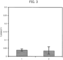
- Fig. 3 is a diagram comparing the measurement results of turbidity.
- series 1 is a result of the turbidity measurement using the culturing device 1 according to the illustrative example
- series 2 is a result of the turbidity measurement using a conventional culturing device without the intermediate plate 13.
- the measurement result does not vary.
- the microplate 12 includes the 96 vessels 14, but the number of the vessels 14 included in the microplate 12 is not limited to the above value.
- the microplate 12 can include an arbitrary number of vessels 14.
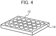
- Fig. 4 is a diagram illustrating the microplate 12 including a total of 24 vessels 14.
- the 24 vessels 14 are arrayed in 6 columns by 4 rows.
- the intermediate plate 13 has 24 convex portions 15.
- cells can be cultured at the same time under different conditions.
- the lid 11, the bottom surface 14A of each of the plurality of vessels 14, and the intermediate plate 13 have desirably substantially the same optical characteristic.
- the lid 11, the bottom surface 14A of each of the plurality of vessels 14, and the intermediate plate 13 may be formed of a material having the same refractive index. In this way, it is possible to prevent the deformation of a target to be observed due to the refraction of the light between the configuring elements and to prevent the lowering of the accuracy of the turbidity measurement.
- the surface of the intermediate plate 13 substantially comes into contact with the lid 11, but the entire surface of the intermediate plate 13 is not necessarily required to come into contact with the lid 11.
- the shape of the lid 11 and the intermediate plate 13 is the shape that prevents dew condensation on the lid 11 due to the adherence of the evaporated culture medium 18.
- a culturing device of a first embodiment is different from the culturing device 1 of the illustrative example in that in place of sandwiching the intermediate plate 13, a component having light transmittance is attached into each of the vessels 14.
- Fig. 5 is a diagram of assistance in explaining the configuration of a culturing device 2 of the first embodiment.
- the culturing device 2 according to the first embodiment includes, in place of the typical microplate 12, a microplate in which a component 23 having light transmittance is attached into each of the vessels 14 included in the microplate 12 described in the illustrative example.
- a material of the component 23 can be selected from the same material as the material forming the lid 11, the microplate 12 and the intermediate plate 13 described in the illustrative example.
- Fig. 5 (a) is a perspective view of assistance in explaining each of the vessels 14 included in the microplate.
- the component 23 illustrated in Fig. 5(a) is bonded to the vessel 14.
- the component 23 has a substantially rectangular parallelepiped shape, and has a curved surface coming into contact with the surface of the interior of the vessel 14.
- Fig. 5(b) is a diagram illustrating the upper surface of each of the vessels 14 into which the component 23 is attached.
- the component 23 is designed to have a size in which the upper opening end of the vessel 14 is not closed, and a surface of the component 23 on the opposite side of the curved surface of the component 23 coming into contact with the vessel 14 is located near the center of the vessel 14. Therefore, like the microplate 12, the vessel 14 included in the microplate has the opening 17.
- the culturing device 2 according to the first embodiment also enables the injection and suction of the liquid from the opening 17.
- Fig. 5 (c) is a side cross-sectional view of the culturing device 2 in which the lid 11 and the microplate are overlapped.
- the component 23 has a surface 23A and a surface 23B substantially parallel to the bottom surface 14A of each of the vessels 14, and the component 23 is attached at a position where the surface 23A substantially comes into contact with the lid 11. That is, the surface 23A of the component 23 is located at the same height as the upper surface of the microplate or at the position slightly higher than the upper surface of the microplate.
- the lid 11 comes into contact with the microplate and the surface 23A of the component 23 so as to close the opening 17 of the vessel 14. In this case, a portion of the lid 11 coming into contact with the surface 23A is not fogged due to the occurrence of dew condensation.
- the lid 11 comes into contact with the surface 23A of the component 23, and covers the opening 17 of the vessel 14 without closing the opening 17. Also in this case, the portion of the lid 11 coming into contact with the surface 23A is not fogged due to the occurrence of dew condensation. It should be noted that although in this case, the opening 17 of the vessel 14 is not completely closed, there is no change to the fact that the lid 11 covers above the opening 17, so that the inclusion of any foreign substances can be prevented. Also, since a gap between the opening 17 and the lid 11 is sufficiently small, the culture medium 18 in the interior of the vessel 14 is hardly evaporated.
- the size of the component 23 is adjusted so that the surface 23B of the component 23 is immersed into the culture medium 18.
- the fogging of the surface 23B of the component 23 due to dew condensation can be prevented, so that the interior of the vessel 14 can be observed satisfactorily, and the measurement accuracy of turbidity can be improved.
- the lid 11, the bottom surface 14A of the vessel 14 and the component 23 preferably have substantially the same optical characteristic.
- the microplate can include an arbitrary number of vessels 14.
- the component 23 having light transmittance is bonded to the interior of each of the vessels 14.
- a culturing device 3 of a second embodiment is different from the culturing device 2 of the first embodiment in that a component 24 having light transmittance is pressed or fitted into the interior of the vessel 14.
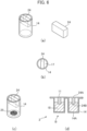
- Fig. 6 is a diagram of assistance in explaining the configuration of the culturing device 3 according to the second embodiment.
- the culturing device 3 includes a microplate in which the component 24 having light transmittance is attached into each of the vessels 14 included in the microplate 12 described in the illustrative example.
- the component 24 has a substantially rectangular parallelepiped shape, and has, at both ends, curved surfaces that can come into contact with the inner surface of the vessel 14.
- a diameter of the component 24 is designed to be slightly larger than an inside diameter of the vessel 14. Therefore, when the component 24 is pressed into the vessel 14, the position of the component 24 can be fixed.
- a material of the component 24 can be selected from the same material as the material forming the lid 11, the microplate 12 and the intermediate plate 13 described in the illustrative example.
- Fig. 6 (a) is a perspective view of assistance in explaining each of the vessels 14 included in the microplate.
- the component 24 illustrated in Fig. 6(a) is pressed into the vessel 14.
- Fig. 6(b) is a diagram illustrating the upper surface of the vessel 14 into which the component 24 is attached.
- the component 24 is designed to have a size and a shape so that the upper opening end of each of the vessels 14 is not closed and the position of the component 24 can be fixed when the component 24 is pressed into the vessel 14. Therefore, like the microplate 12, the vessel 14 included in the microplate has the opening 17.
- the culture vessel 2 according to the first embodiment also enables the injection and suction of the liquid from the opening 17.
- Fig. 6(c) is a diagram illustrating a state where an antibacterial agent 25 is coated onto the bottom surface in the interior of each of the vessels 14 in freeze-dried state.
- the antibacterial agent 25 is desirably coated onto the bottom surface of the vessel 14 before the component 24 is pressed into the vessel 14.
- the antibacterial agent 25 is dissolved to prepare the culture medium 18 and the antibacterial agent 25 necessary for conducting an antibacterial susceptibility test at appropriate concentration.
- the antibacterial agent 25 or the culture medium 18 in freeze-dried state is previously accommodated in the interior of the vessel 14, so that by adding the necessary liquid, the culturing of cells can be easily started.
- Fig. 6(d) is a cross-sectional view of the culturing device 3 in which the lid 11 and the microplate are overlapped.
- the component 24 has a surface 24A and a surface 24B substantially parallel to the bottom surface 14A of each of the vessels 14, and the component 24 is attached at the position where the surface 24A substantially comes into contact with the lid 11. That is, like the component 23, the surface 24A of the component 24 is located at the same height as the upper surface of the microplate or at the position slightly higher than the upper surface of the microplate.
- a length of the component 24 is adjusted so that the surface 24B of the component 24 is immersed into the culture medium 18.
- the fogging of the surface 24B of the component 24 due to dew condensation can be prevented, so that the interior of the vessel 14 can be observed satisfactorily.
- the measurement accuracy of turbidity can be improved.
- the lid 11, the bottom surface 14A of the vessel 14 and the component 24 preferably have substantially the same optical characteristic.
- the microplate can include an arbitrary number of vessels 14.
- the attaching position of the component 24 is preferably the position suitable for the observation of the interior of the vessel 14.
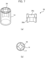
- Fig. 7 is a diagram illustrating another example of the component 24 pressed into each of the vessels 14.
- protrusions 26b extend in four directions from a center portion 26a in a cylindrical shape. That is, unlike the component 24, the component 26 is configured to thrust in two directions, and the opening 17 that the vessel 14 has is divided into four.
- the vessel 14 into which the component 26 is pressed enables the injection and suction of the liquid from the opening 17.
- the component 26 is designed so that a diameter of the component 26 is slightly larger than the diameter of the interior of the vessel 14, and can be pressed or fitted into the vessel 14.
- the component 26 has an upper surface and a lower surface substantially parallel to the bottom surface 14A of the vessel 14, and the component 26 is attached at a position where the upper surface of the component 26 substantially comes into contact with the lid 11. That is, like the component 24, the upper surface of the component 26 is located at the same height as the upper surface of the microplate or at the position higher than the upper surface of the microplate.
- the material of the component 26 the same material as the material of the component 24 can be selected.
- the center portion 26a of the component 26 is cylindrical, and the component 26 makes an observation region when the optical measurement is performed wider than the component 24. Also, the component 26 makes the opening 17 narrower than the component 24, so that the liquid is hard to be spilled when the culturing device 3 is conveyed.
- Fig. 8 is a diagram of assistance in explaining a state where the component 26 prevents dew condensation on the lid 11.
- each of the vessels 14 shown at an upper portion is the vessel 14 into which the culture medium 18 is not injected
- the vessel 14 shown at a center of a middle portion is the vessel 14 into which the component 26 is attached
- each of other vessels 14 is the conventional vessel 14 into which the culture medium 18 is injected.
- the lid 11 is not fogged at a portion located above the component 26.
- the lid 11 is not fogged at the portion of the lid 11 located above the component 23, and in the case of the vessel 14 into which the component 24 is attached, the lid 11 is not fogged at the portion of the lid 11 located above the component 24. Also, likewise, in the illustrative example, the lid 11 is not fogged at the portion of the lid 11 located above the convex portion 15 included in the intermediate plate 13.
- the culturing device may be provided in a state where an antibacterial agent 27 that is frozen is accommodated in each of the vessels 14.
- the antibacterial agent 27 in the culturing device that is freeze-kept is dissolved at room temperature, and by adding the necessary culture medium 18 and specimen, a medium suitable for the antibacterial susceptibility test can be prepared. It should be noted that, not only the antibacterial agent 27, but also the culture medium 18 and other chemical agents, may be accommodated in frozen state.
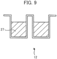
- Fig. 9 is a diagram illustrating the microplate 12 in which the antibacterial agent 27 and the culture medium 18 in frozen state are accommodated.
- the antibacterial agent 27 and the culture medium 18 in frozen state are previously accommodated in the microplate 12, for example, after they are unfrozen at room temperature, as illustrated in Fig. 1(c) , the intermediate plate 13 and the lid 11 are overlapped with the microplate 12, so that the culturing of cells can be easily started.
Landscapes
- Health & Medical Sciences (AREA)
- Chemical & Material Sciences (AREA)
- Life Sciences & Earth Sciences (AREA)
- Engineering & Computer Science (AREA)
- Bioinformatics & Cheminformatics (AREA)
- Organic Chemistry (AREA)
- Wood Science & Technology (AREA)
- Zoology (AREA)
- General Health & Medical Sciences (AREA)
- Biochemistry (AREA)
- Biotechnology (AREA)
- Microbiology (AREA)
- Sustainable Development (AREA)
- General Engineering & Computer Science (AREA)
- Biomedical Technology (AREA)
- Genetics & Genomics (AREA)
- Clinical Laboratory Science (AREA)
- Analytical Chemistry (AREA)
- Physics & Mathematics (AREA)
- Chemical Kinetics & Catalysis (AREA)
- General Physics & Mathematics (AREA)
- Immunology (AREA)
- Pathology (AREA)
- Plasma & Fusion (AREA)
- Molecular Biology (AREA)
- Medicinal Chemistry (AREA)
- Spectroscopy & Molecular Physics (AREA)
- Hematology (AREA)
- Apparatus Associated With Microorganisms And Enzymes (AREA)
Description
- This invention relates to a culturing device used for examining bacteria, fungi, and the like.
- Conventionally, a culture medium and cells are introduced into a culture vessel to culture the cells. When the cells are cultured, a lid is disposed on the culture vessel for the purpose of the prevention of the infection of the cells with bacteria, the inhibition of the increase in the pH of the culture medium, and the like. The observation of the change in the form with time, the motility, the invasive ability, and the like of the culture cells is often performed while the lid is disposed on the culture vessel.
- To completely prevent dew condensation on a microscope observation portion in the interior of a culture lid and to inhibit the change in the amount used and the pH of a culture medium,
Patent Literature 1 discloses a cell incubator for microscope including a culture dish and a lid provided in its center portion with a recessed portion. -
- Patent Literature 1:
Japanese Unexamined Utility Model Application Publication No. 3104790
US 2016/250632 A1 discloses a culturing device with the features in the preamble ofpresent claim 1. Another example of such a conventional device is described inJP 2016 026474 A - In using the cell culture vessel for microscope described in
Patent Literature 1, when the operation of adding a reagent to the culture medium or extracting part of the culture medium is performed, the lid is required to be removed. Here, since the recessed portion of the lid is immersed into the culture medium, the culture medium adheres to the lid removed from the culture vessel. - Therefore, when the cell culture vessel for microscope according to
Patent Literature 1 is applied to the well of the microplate, there is a possibility that, into the well, the culture medium from the adjacent well having different culture conditions is mixed at the time of performing the operation of removing the lid. On the other hand, when the opening is simply provided in the lid to eliminate the operation of removing the lid, the infection with bacteria cannot be prevented. - This disclosure has been made in view of the above points, and provides a culturing device where an interior of each of culture vessels can be observed with high accuracy and that can reduce a risk of contamination.
- This disclosure (not claimed) includes a plurality of means for solving the above problems, and as an example, provides a culturing device including a microplate having a plurality of vessels, each of the vessels having a bottom surface having light transmittance and having an opening at an upper portion, a lid having light transmittance and covering an upper surface of the microplate, and an intermediate plate having light transmittance and being sandwiched between the lid and the microplate, the intermediate plate having a plurality of convex portions on a surface of the intermediate plate facing the microplate, provided with a plurality of through holes corresponding to the plurality of convex portions. The plurality of convex portions and the plurality of through holes are disposed so that when the intermediate plate and the microplate are overlapped, each of the plurality of convex portions is inserted into each of the plurality of vessels and each of the plurality of through holes coincides with the opening of each of the plurality of vessels. The lid comes into contact with the intermediate plate so as to close the plurality of through holes provided in the intermediate plate.
- As a means for solving the above problems, the present invention provides a culturing device as defined in
claim 1. It includes a microplate including a plurality of vessels, each of the plurality of vessels having a bottom surface having light transmittance and a component attached into the vessel, the component extending from an upper end of the vessel to an interior of the vessel so as to have an opening and having light transmittance, and a lid having light transmittance and covering an upper surface of the microplate. The component has two surfaces substantially parallel to the bottom surface of the vessel, one of the two faces being located at the same height as the upper surface of the microplate or at a position higher than the upper surface of the microplate. - According to this invention, the observation of the interior of each of the culture vessels can be performed satisfactorily, and the risk of contamination can be reduced. Objects, configurations and effects other than the above will be apparent from the description of the following embodiments.
-
-
Fig. 1 is a diagram of assistance in explaining the configuration of a culturing device according to an illustrative example useful to understand the present invention. -
Fig. 2 is a diagram of assistance in explaining an optical system for measuring turbidity. -
Fig. 3 is a diagram comparing measurement results of turbidity. -
Fig. 4 is a diagram illustrating a first plate including a total of 24 vessels. -
Fig. 5 is a diagram of assistance in explaining the configuration of a culturing device according to a first embodiment. -
Fig. 6 is a diagram of assistance in explaining the configuration of a culturing device according to a second embodiment. -
Fig. 7 is a diagram illustrating another example of a component pressed into the vessel. -
Fig. 8 is a diagram of assistance in explaining a state where the component prevents dew condensation on a lid. -
Fig. 9 is a diagram illustrating the first plate in which a frozen antibacterial agent is accommodated in the vessels. - When cells are cultured by using a culturing device, a lid is typically disposed so as to close an opening of each of vessels in order to prevent the intrusion of bacteria and the like. Since the cells are cultured at temperatures of approximately 30°C to 35°C, a culture medium is evaporated to often fog the lid. The fogging of the lid causes trouble in observing an interior of the vessel, and for example, it is difficult to precisely measure turbidity of the culture medium.
- In the culturing device of this disclosure, an intermediate plate or a component having light transmittance is sandwiched between the lid and the culture medium, so that the lid is not fogged at a position above each of convex portions included in the intermediate plate or above the component. Therefore, in the culturing device of this disclosure, the interior of the vessel can be observed through part of the lid.
- The intermediate plate or the component is configured not to cover the entire opening of the vessel. For that, in the culturing device of this disclosure, a reagent can be injected into the interior of the vessel even without removing the intermediate plate or the component. Therefore, unlike a case where the lid to which a large amount of the culture medium adheres is removed to inject the reagent, in the culturing device of this disclosure, a risk of contamination can be reduced. Also, in the culturing device of this disclosure, part of the member is immersed into the culture medium, so that the interior of the vessel can be observed satisfactorily through the lid and the member.
- Various embodiments of this disclosure will be described below with reference to the accompanying drawings. However, these embodiments are illustrative only for achieving the present invention, and do not limit the technical range of this disclosure. Also, the configurations shared among the respective drawings are indicated by the same reference numerals.
-
Fig. 1 is a diagram of assistance in explaining the configuration of aculturing device 1 according to the illustrative example useful to understand the present invention. Theculturing device 1 includes alid 11, amicroplate 12 and anintermediate plate 13.Fig. 1(a) is a perspective view illustrating thelid 11, themicroplate 12, a portion enlargedly illustrating a surface of theintermediate plate 13 coming into contact with themicroplate 12, andvessels 14 included in themicroplate 12. - The shape of the
lid 11 is substantially planar, and one of surfaces of thelid 11 comes into contact with one of surfaces of theintermediate plate 13. Thelid 11 has light transmittance, and covers an upper surface of themicroplate 12. - The
microplate 12 includes a plurality of thevessels 14 each having an opening at an upper portion. Each of thevessels 14 accommodates a culture medium and the like. In the example illustrated inFig. 1(a) , themicroplate 12 includes a total of 96vessels 14 arrayed in 12 columns by 8 rows. - The
intermediate plate 13 is used by being sandwiched between thelid 11 and themicroplate 12. Theintermediate plate 13 has a plurality ofconvex portions 15 on the surface of theintermediate plate 13 facing themicroplate 12, and in a periphery of each of the plurality ofconvex portions 15, each of a plurality of throughholes 16 is provided. InFig. 1(a) , only two of the plurality ofconvex portions 15 are illustrated, but for example, the plurality ofconvex portions 15 equal in number to that of thevessels 14 included in themicroplate 12 are provided on theintermediate plate 13. - The plurality of
convex portions 15 and the plurality of throughholes 16 included in theintermediate plate 13 are disposed so that when theintermediate plate 13 and themicroplate 12 are overlapped, each of the plurality ofconvex portions 15 is inserted into each of the plurality ofvessels 14 and each of the plurality of throughholes 16 coincides with an opening 17 of each of the plurality ofvessels 14. Thelid 11 comes into contact with theintermediate plate 13 so as to close the plurality of throughholes 16 provided in theintermediate plate 13. -
Fig. 1(b) is a diagram illustrating a state of an upper surface of each of thevessels 14 when themicroplate 12 and theintermediate plate 13 are overlapped. In the example illustrated inFig. 1(b) , each of theconvex portions 15 of theintermediate plate 13 is disposed so as to be located at a center of thevessel 14. Also, theopening 17 of thevessel 14 included in themicroplate 12 is not completely covered due to the presence of each of the throughholes 16 included in theintermediate plate 13 in a state where thelid 11 is not overlapped with theintermediate plate 13. Therefore, the interior of each of thevessels 14 can be accessed through the throughhole 16. - In the
culturing device 1, a liquid can be added and suctioned from the throughhole 16 of theintermediate plate 13 by removing thelid 11. For example, a reagent for identifying bacteria can be injected from the throughhole 16 into each of thevessels 14. When the culture medium is changed in color after the injection of the reagent, it is possible to determine that bacteria grow in the culture medium. - Examples of the reagent added to the
vessel 14 include a Kovac's reagent for determining that indole has been generated, sodium hydroxide and α-naphthol for determining a VP (Voges-Proskauer) reaction, a sulfanilic acid and an α-naphthylamine solution for determining a silver nitrate reducibility, phenol red, bromocresol purple, and bromothymol blue that are pH indicators, and the like. -
Fig. 1(c) is a side cross-sectional view illustrating a state where each of the plurality ofvessels 14 accommodates aculture medium 18, and thelid 11, themicroplate 12 and theintermediate plate 13 are overlapped. As illustrated inFig. 1(c) , each of the plurality ofconvex portions 15 has a surface15A substantially parallel to abottom surface 14A of each of the plurality ofvessels 14 when theintermediate plate 13 is overlapped with themicroplate 12. - As illustrated in
Fig. 1(c) , for example, a length of theconvex portion 15 is adjusted so that thesurface 15A is immersed into theculture medium 18. Also, of the surfaces that theintermediate plate 13 has, the surface coming into contact with thelid 11 is located at a position higher than an upper edge of theopening 17 of thevessel 14. Thelid 11 and theintermediate plate 13 are in substantially contact with each other without sandwiching an air layer, or thelid 11 and the portion of theintermediate plate 13 having theconvex portion 15 are in contact with each other without sandwiching an air layer. Therefore, when theculturing device 1 is used, the light is prevented from being refracted, so that the interior of thevessel 14 can be observed satisfactorily. - In the
culturing device 1 of this disclosure, to achieve desired optical measurement, thelid 11, theintermediate plate 13 and at least thebottom surface 14A portion of each of thevessels 14 of themicroplate 12 are formed of a material having light transmittance. Examples of the material having light transmittance used for theculturing device 1 of this disclosure include, for example, polypropylene, polystyrene, and polycarbonate. - The effects exhibited by the
culturing device 1 according to the illustrative example:
In theculturing device 1 according to the illustrative example, each of thelid 11 and theintermediate plate 13 has light transmittance. Also, when a position of a liquid level of theculture medium 18 is located at a position where thesurface 15A of each of theconvex portions 15 is immersed, thesurface 15A of theconvex portion 15 is not fogged due to the dew condensation of the evaporatedculture medium 18. Further, a portion of thelid 11 located on an upper portion of theconvex portion 15 of theintermediate plate 13 is not fogged. Therefore, when theculturing device 1 according to the illustrative example is used, the interior of each of thevessels 14 can be observed satisfactorily through thesurface 15A even in the state where thelid 11 and theintermediate plate 13 are overlapped with themicroplate 12. - Also, in the
microplate 12, at least thebottom surface 14A of each of thevessels 14 is formed of the material having light transmittance, so that theculturing device 1 of this disclosure can measure the turbidity of theculture medium 18 accommodated in thevessel 14 by using a dichroic mirror and a photodiode. - Also, in each of the plurality of
vessels 14, each of the throughholes 16 coincides with theopening 17 in the state where theintermediate plate 13 is overlapped with themicroplate 12. Therefore, in theculturing device 1, the injection of the reagent and the extraction of the culture medium are enabled from the throughhole 16 by removing thelid 11 even without removing theintermediate plate 13 to which a large amount of theculture medium 18 adheres. Therefore, in theculturing device 1, theculture medium 18 having different ingredients can be prevented from mixing into each other. -
Fig. 2 is a diagram of assistance in explaining an optical system S for measuring turbidity. The optical system S includes alight source 19, adichroic mirror 20, a first photodiode (PD) 21, a second photodiode (PD) 22 and theculturing device 1. - Part of a light emitted from the
light source 19 transmits through thedichroic mirror 20, and another part of the light is reflected by thedichroic mirror 20. The light transmitted through thedichroic mirror 20 is detected by thefirst photodiode 21. The light reflected by thedichroic mirror 20 transmits through thelid 11, theintermediate plate 13, theculture medium 18 and thebottom surface 14A of each of thevessels 14 of theculturing device 1, and is detected by thesecond photodiode 22. The turbidity of theculture medium 18 can be measured by comparing the light amount detected by thefirst photodiode 21 and the light amount detected by thesecond photodiode 22. It should be noted that in the optical system S, thedichroic mirror 20 may be a semi-transparent mirror. -
Fig. 3 is a diagram comparing the measurement results of turbidity. InFig. 3 ,series 1 is a result of the turbidity measurement using theculturing device 1 according to the illustrative example, andseries 2 is a result of the turbidity measurement using a conventional culturing device without theintermediate plate 13. As illustrated inFig. 3 , in theculturing device 1 of this disclosure, since no dew condensation occurs on thelid 11, it is found that the measurement result does not vary. - In the above description, the
microplate 12 includes the 96vessels 14, but the number of thevessels 14 included in themicroplate 12 is not limited to the above value. Themicroplate 12 can include an arbitrary number ofvessels 14. -
Fig. 4 is a diagram illustrating themicroplate 12 including a total of 24vessels 14. In the example illustrated inFig. 4 , the 24vessels 14 are arrayed in 6 columns by 4 rows. It should be noted that in this case, theintermediate plate 13 has 24convex portions 15. As described above, when themicroplate 12 includes the plurality ofvessels 14, cells can be cultured at the same time under different conditions. - The
lid 11, thebottom surface 14A of each of the plurality ofvessels 14, and theintermediate plate 13 have desirably substantially the same optical characteristic. Specifically, thelid 11, thebottom surface 14A of each of the plurality ofvessels 14, and theintermediate plate 13 may be formed of a material having the same refractive index. In this way, it is possible to prevent the deformation of a target to be observed due to the refraction of the light between the configuring elements and to prevent the lowering of the accuracy of the turbidity measurement. - In the above description, the surface of the
intermediate plate 13 substantially comes into contact with thelid 11, but the entire surface of theintermediate plate 13 is not necessarily required to come into contact with thelid 11. The shape of thelid 11 and theintermediate plate 13 is the shape that prevents dew condensation on thelid 11 due to the adherence of the evaporatedculture medium 18. - In the configuration of the
culturing device 1 of the illustrative example, theintermediate plate 13 having theconvex portions 15 and the throughholes 16 is sandwiched between thelid 11 and themicroplate 12. On the contrary, a culturing device of a first embodiment is different from theculturing device 1 of the illustrative example in that in place of sandwiching theintermediate plate 13, a component having light transmittance is attached into each of thevessels 14. -
Fig. 5 is a diagram of assistance in explaining the configuration of aculturing device 2 of the first embodiment. Theculturing device 2 according to the first embodiment includes, in place of thetypical microplate 12, a microplate in which acomponent 23 having light transmittance is attached into each of thevessels 14 included in themicroplate 12 described in the illustrative example. A material of thecomponent 23 can be selected from the same material as the material forming thelid 11, themicroplate 12 and theintermediate plate 13 described in the illustrative example. -
Fig. 5 (a) is a perspective view of assistance in explaining each of thevessels 14 included in the microplate. Thecomponent 23 illustrated inFig. 5(a) is bonded to thevessel 14. As illustrated inFig. 5(a) , thecomponent 23 has a substantially rectangular parallelepiped shape, and has a curved surface coming into contact with the surface of the interior of thevessel 14. -
Fig. 5(b) is a diagram illustrating the upper surface of each of thevessels 14 into which thecomponent 23 is attached. As illustrated inFig. 5(b) , thecomponent 23 is designed to have a size in which the upper opening end of thevessel 14 is not closed, and a surface of thecomponent 23 on the opposite side of the curved surface of thecomponent 23 coming into contact with thevessel 14 is located near the center of thevessel 14. Therefore, like themicroplate 12, thevessel 14 included in the microplate has theopening 17. Theculturing device 2 according to the first embodiment also enables the injection and suction of the liquid from theopening 17. -
Fig. 5 (c) is a side cross-sectional view of theculturing device 2 in which thelid 11 and the microplate are overlapped. As illustrated inFig. 5(c) , thecomponent 23 has asurface 23A and asurface 23B substantially parallel to thebottom surface 14A of each of thevessels 14, and thecomponent 23 is attached at a position where thesurface 23A substantially comes into contact with thelid 11. That is, thesurface 23A of thecomponent 23 is located at the same height as the upper surface of the microplate or at the position slightly higher than the upper surface of the microplate. - When the
component 23 is attached so that thesurface 23A of thecomponent 23 is located at the same height as the upper surface of the microplate, thelid 11 comes into contact with the microplate and thesurface 23A of thecomponent 23 so as to close theopening 17 of thevessel 14. In this case, a portion of thelid 11 coming into contact with thesurface 23A is not fogged due to the occurrence of dew condensation. - Also, when the
component 23 is attached so that thesurface 23A of thecomponent 23 is higher than the upper surface of the microplate, thelid 11 comes into contact with thesurface 23A of thecomponent 23, and covers theopening 17 of thevessel 14 without closing theopening 17. Also in this case, the portion of thelid 11 coming into contact with thesurface 23A is not fogged due to the occurrence of dew condensation. It should be noted that although in this case, theopening 17 of thevessel 14 is not completely closed, there is no change to the fact that thelid 11 covers above theopening 17, so that the inclusion of any foreign substances can be prevented. Also, since a gap between theopening 17 and thelid 11 is sufficiently small, theculture medium 18 in the interior of thevessel 14 is hardly evaporated. - For example, the size of the
component 23 is adjusted so that thesurface 23B of thecomponent 23 is immersed into theculture medium 18. In this way, the fogging of thesurface 23B of thecomponent 23 due to dew condensation can be prevented, so that the interior of thevessel 14 can be observed satisfactorily, and the measurement accuracy of turbidity can be improved. - It should be noted that as in the case with the illustrative example, the
lid 11, thebottom surface 14A of thevessel 14 and thecomponent 23 preferably have substantially the same optical characteristic. Also, the microplate can include an arbitrary number ofvessels 14. - In the
culturing device 2 of the first embodiment, thecomponent 23 having light transmittance is bonded to the interior of each of thevessels 14. Aculturing device 3 of a second embodiment is different from theculturing device 2 of the first embodiment in that acomponent 24 having light transmittance is pressed or fitted into the interior of thevessel 14. -
Fig. 6 is a diagram of assistance in explaining the configuration of theculturing device 3 according to the second embodiment. Theculturing device 3 includes a microplate in which thecomponent 24 having light transmittance is attached into each of thevessels 14 included in themicroplate 12 described in the illustrative example. - The
component 24 has a substantially rectangular parallelepiped shape, and has, at both ends, curved surfaces that can come into contact with the inner surface of thevessel 14. A diameter of thecomponent 24 is designed to be slightly larger than an inside diameter of thevessel 14. Therefore, when thecomponent 24 is pressed into thevessel 14, the position of thecomponent 24 can be fixed. A material of thecomponent 24 can be selected from the same material as the material forming thelid 11, themicroplate 12 and theintermediate plate 13 described in the illustrative example. -
Fig. 6 (a) is a perspective view of assistance in explaining each of thevessels 14 included in the microplate. Thecomponent 24 illustrated inFig. 6(a) is pressed into thevessel 14.Fig. 6(b) is a diagram illustrating the upper surface of thevessel 14 into which thecomponent 24 is attached. - As illustrated in
Fig. 6(b) , thecomponent 24 is designed to have a size and a shape so that the upper opening end of each of thevessels 14 is not closed and the position of thecomponent 24 can be fixed when thecomponent 24 is pressed into thevessel 14. Therefore, like themicroplate 12, thevessel 14 included in the microplate has theopening 17. Theculture vessel 2 according to the first embodiment also enables the injection and suction of the liquid from theopening 17. -
Fig. 6(c) is a diagram illustrating a state where anantibacterial agent 25 is coated onto the bottom surface in the interior of each of thevessels 14 in freeze-dried state. Theantibacterial agent 25 is desirably coated onto the bottom surface of thevessel 14 before thecomponent 24 is pressed into thevessel 14. When theculture medium 18 is injected from theopening 17 into thevessel 14, theantibacterial agent 25 is dissolved to prepare theculture medium 18 and theantibacterial agent 25 necessary for conducting an antibacterial susceptibility test at appropriate concentration. As described above, theantibacterial agent 25 or theculture medium 18 in freeze-dried state is previously accommodated in the interior of thevessel 14, so that by adding the necessary liquid, the culturing of cells can be easily started. -
Fig. 6(d) is a cross-sectional view of theculturing device 3 in which thelid 11 and the microplate are overlapped. As illustrated inFig. 6(d) , thecomponent 24 has asurface 24A and asurface 24B substantially parallel to thebottom surface 14A of each of thevessels 14, and thecomponent 24 is attached at the position where thesurface 24A substantially comes into contact with thelid 11. That is, like thecomponent 23, thesurface 24A of thecomponent 24 is located at the same height as the upper surface of the microplate or at the position slightly higher than the upper surface of the microplate. - For example, a length of the
component 24 is adjusted so that thesurface 24B of thecomponent 24 is immersed into theculture medium 18. In this way, the fogging of thesurface 24B of thecomponent 24 due to dew condensation can be prevented, so that the interior of thevessel 14 can be observed satisfactorily. As a result, the measurement accuracy of turbidity can be improved. - It should be noted that like the first embodiment, the
lid 11, thebottom surface 14A of thevessel 14 and thecomponent 24 preferably have substantially the same optical characteristic. Also, the microplate can include an arbitrary number ofvessels 14. The attaching position of thecomponent 24 is preferably the position suitable for the observation of the interior of thevessel 14. -
Fig. 7 is a diagram illustrating another example of thecomponent 24 pressed into each of thevessels 14. In acomponent 26 illustrated inFig. 7 ,protrusions 26b extend in four directions from acenter portion 26a in a cylindrical shape. That is, unlike thecomponent 24, thecomponent 26 is configured to thrust in two directions, and theopening 17 that thevessel 14 has is divided into four. Thevessel 14 into which thecomponent 26 is pressed enables the injection and suction of the liquid from theopening 17. - Also, like the
component 24, thecomponent 26 is designed so that a diameter of thecomponent 26 is slightly larger than the diameter of the interior of thevessel 14, and can be pressed or fitted into thevessel 14. Thecomponent 26 has an upper surface and a lower surface substantially parallel to thebottom surface 14A of thevessel 14, and thecomponent 26 is attached at a position where the upper surface of thecomponent 26 substantially comes into contact with thelid 11. That is, like thecomponent 24, the upper surface of thecomponent 26 is located at the same height as the upper surface of the microplate or at the position higher than the upper surface of the microplate. As the material of thecomponent 26, the same material as the material of thecomponent 24 can be selected. - The
center portion 26a of thecomponent 26 is cylindrical, and thecomponent 26 makes an observation region when the optical measurement is performed wider than thecomponent 24. Also, thecomponent 26 makes theopening 17 narrower than thecomponent 24, so that the liquid is hard to be spilled when theculturing device 3 is conveyed. -
Fig. 8 is a diagram of assistance in explaining a state where thecomponent 26 prevents dew condensation on thelid 11. InFig. 8 , each of thevessels 14 shown at an upper portion is thevessel 14 into which theculture medium 18 is not injected, thevessel 14 shown at a center of a middle portion is thevessel 14 into which thecomponent 26 is attached, and each ofother vessels 14 is theconventional vessel 14 into which theculture medium 18 is injected. As illustrated inFig. 8 , it is found that in the case of thevessel 14 into which thecomponent 26 is attached, thelid 11 is not fogged at a portion located above thecomponent 26. Although not illustrated, likewise, in the case of thevessel 14 into which thecomponent 23 is attached, thelid 11 is not fogged at the portion of thelid 11 located above thecomponent 23, and in the case of thevessel 14 into which thecomponent 24 is attached, thelid 11 is not fogged at the portion of thelid 11 located above thecomponent 24. Also, likewise, in the illustrative example, thelid 11 is not fogged at the portion of thelid 11 located above theconvex portion 15 included in theintermediate plate 13. - The culturing device may be provided in a state where an
antibacterial agent 27 that is frozen is accommodated in each of thevessels 14. In that case, theantibacterial agent 27 in the culturing device that is freeze-kept is dissolved at room temperature, and by adding thenecessary culture medium 18 and specimen, a medium suitable for the antibacterial susceptibility test can be prepared. It should be noted that, not only theantibacterial agent 27, but also theculture medium 18 and other chemical agents, may be accommodated in frozen state. -
Fig. 9 is a diagram illustrating themicroplate 12 in which theantibacterial agent 27 and theculture medium 18 in frozen state are accommodated. When theantibacterial agent 27 and theculture medium 18 in frozen state are previously accommodated in themicroplate 12, for example, after they are unfrozen at room temperature, as illustrated inFig. 1(c) , theintermediate plate 13 and thelid 11 are overlapped with themicroplate 12, so that the culturing of cells can be easily started. - It should be noted that this disclosure is not limited to the above embodiments, and includes various modifications. For example, the above embodiments have been described in detail to simply describe the present invention, and do not necessarily include all the described configurations. Also, part of the configuration of one embodiment can be replaced with the configurations of other embodiments, and in addition, the configuration of one embodiment can be added with the configurations of other embodiments . Also, part of the configuration of each of the embodiments can be subjected to addition, deletion, and replacement with respect to other configurations.
-
- 1, 2, 3
- Culturing device
- 11
- Lid
- 12A, 12B, 12C
- Microplate
- 13
- Intermediate plate
- 14
- Vessel
- 15
- Convex portion
- 16
- Through hole
- 17
- Opening
- 18
- Culture medium
- 20
- Dichroic mirror
- 23, 24, 26
- Component
- 25
- Antibacterial agent
- 26a
- Center portion
- 26b
- Protrusion
- 27
- Antibacterial agent in frozen state
Claims (7)
- A culturing device (1-3) comprising:a microplate (12) including a plurality of vessels (14) for accommodating a culture medium (18), each of the plurality of vessels (14) having a bottom surface (14A) and a component (24; 24; 26) attached into the vessel, the component (23; 24; 26) extending from an upper end of the vessel (14) to an interior of the vessel (14) so that the vessel has an opening (17); anda lid (11) covering an upper surface of the microplate (12),wherein the component (23; 24; 26) has two surfaces (23A, 23B; 24A, 24B) substantially parallel to the bottom surface (14A) of the vessel (14), one (23A; 24A) of the two surfaces being located at the same height as the upper surface of the microplate (12) or at a position higher than the upper surface of the microplate (12),characterised in thatthe bottom surface (14A) of the vessels (14), the component (23; 24; 26) and the lid (11) each have light transmittance, andthe size of the component (23, 24, 26) is adjusted so that the other (23B; 24B) of the two surfaces is immersed into the culture medium (18) accommodated in the vessel (14) when in use.
- The culturing device (1-3) according to claim 1, wherein the lid (11), the bottom surface (14A) of each of the plurality of vessels (14) and the component (23; 24; 26) have substantially the same optical characteristic.
- The culturing device (1-3) according to claim 1, wherein in the interior of each of the plurality of vessels (14), an antibacterial agent (25) in freeze-dried state is accommodated.
- The culturing device (1-3) according to claim 1, wherein in the interior of each of the plurality of vessels (14), an antibacterial agent (27) or a culture medium ingredient in frozen state is accommodated.
- The culturing device (1-3) according to claim 1, wherein the microplate (12) includes 24 or more vessels (14).
- The culturing device (1-3) according to claim 1, wherein the component (23; 24; 26) is bonded and attached into the vessel.
- The culturing device (1-3) according to claim 1, wherein the component (23; 24; 26) is pressed and attached into the vessel.
Applications Claiming Priority (1)
| Application Number | Priority Date | Filing Date | Title |
|---|---|---|---|
| PCT/JP2016/087301 WO2018109886A1 (en) | 2016-12-14 | 2016-12-14 | Culture instrument |
Publications (3)
| Publication Number | Publication Date |
|---|---|
| EP3556844A1 EP3556844A1 (en) | 2019-10-23 |
| EP3556844A4 EP3556844A4 (en) | 2020-07-22 |
| EP3556844B1 true EP3556844B1 (en) | 2023-11-01 |
Family
ID=62558185
Family Applications (1)
| Application Number | Title | Priority Date | Filing Date |
|---|---|---|---|
| EP16924151.0A Active EP3556844B1 (en) | 2016-12-14 | 2016-12-14 | Culture instrument |
Country Status (5)
| Country | Link |
|---|---|
| US (1) | US11618873B2 (en) |
| EP (1) | EP3556844B1 (en) |
| JP (1) | JP6832954B2 (en) |
| CN (1) | CN110023480B (en) |
| WO (1) | WO2018109886A1 (en) |
Families Citing this family (4)
| Publication number | Priority date | Publication date | Assignee | Title |
|---|---|---|---|---|
| KR102193016B1 (en) * | 2018-12-17 | 2020-12-18 | 엠비디 주식회사 | Bio chip pillar structure |
| CN110992784B (en) * | 2019-11-20 | 2021-11-09 | 万有造诣(深圳)教育科技有限公司 | Scientific test device for education and science and technology |
| US12529649B2 (en) | 2021-08-08 | 2026-01-20 | Cytena Bioprocess Solutions Co., Ltd | Image acquisition system for acquiring an image of a liquid sample |
| TWM647074U (en) * | 2023-02-02 | 2023-10-11 | 新原生細胞製備股份有限公司 | Three-dimensional culture device and biological culture equipment |
Family Cites Families (21)
| Publication number | Priority date | Publication date | Assignee | Title |
|---|---|---|---|---|
| US4720463A (en) | 1985-03-01 | 1988-01-19 | Sherwood Medical Company | Automated microbiological testing apparatus |
| JP2876080B2 (en) | 1989-09-16 | 1999-03-31 | 本田技研工業株式会社 | Engine cover device for motorcycle |
| US5141718A (en) * | 1990-10-30 | 1992-08-25 | Millipore Corporation | Test plate apparatus |
| WO1994004703A1 (en) * | 1992-08-21 | 1994-03-03 | Showa Yakuhin Kako Co., Ltd. | Chemical and microbial test device |
| US5366893A (en) * | 1993-01-13 | 1994-11-22 | Becton, Dickinson And Company | Culture vessel |
| US6153400A (en) * | 1999-03-12 | 2000-11-28 | Akzo Nobel N.V. | Device and method for microbial antibiotic susceptibility testing |
| DE10204531A1 (en) | 2002-02-01 | 2003-08-21 | Inst Chemo Biosensorik | cover element |
| JP3104790U (en) | 2004-04-22 | 2004-10-14 | 有限会社金沢大学ティ・エル・オー | Microscope cell incubator |
| ES2704039T3 (en) * | 2005-06-10 | 2019-03-13 | Nunc As | Culture insertion element holder, culture insertion element and culture insertion element system |
| JP2007300853A (en) * | 2006-05-11 | 2007-11-22 | Nikon Corp | Culture container and automatic culture equipment |
| US20090082600A1 (en) * | 2007-06-06 | 2009-03-26 | Shengde Zhou | Native homoethanol Pathway for ethanol production in E. coli |
| CN102719352B (en) | 2012-06-06 | 2014-01-29 | 西安交通大学 | Cell chip slide for preparing microarray cell chips and preparation method |
| CN103013829B (en) * | 2012-12-28 | 2015-04-22 | 江南大学 | Structure of deep-well cell culture plate cover |
| US9790465B2 (en) * | 2013-04-30 | 2017-10-17 | Corning Incorporated | Spheroid cell culture well article and methods thereof |
| JP5768174B1 (en) * | 2014-06-24 | 2015-08-26 | 日本写真印刷株式会社 | Culture vessel |
| CN203960224U (en) * | 2014-08-06 | 2014-11-26 | 青岛易邦生物工程有限公司 | Novel cell culture plate |
| JP6479368B2 (en) * | 2014-08-18 | 2019-03-06 | オリンパス株式会社 | Culture container, multiphoton excitation microscope, and observation method |
| JP5731704B1 (en) | 2014-09-05 | 2015-06-10 | 日本写真印刷株式会社 | Culture vessel |
| BR112017018259B1 (en) | 2015-02-27 | 2023-11-28 | Mastaplex Limited | METHOD FOR PERFORMING AN ANTIMICROBIAL SUSCEPTIBILITY TEST AND TEST KIT |
| WO2016138338A1 (en) * | 2015-02-27 | 2016-09-01 | Corning Incorporated | Fitted lid for multi-well plate |
| CN204874491U (en) * | 2015-07-17 | 2015-12-16 | 杭州秀川科技有限公司 | Board is cultivateed to bacterium |
-
2016
- 2016-12-14 US US16/464,830 patent/US11618873B2/en active Active
- 2016-12-14 EP EP16924151.0A patent/EP3556844B1/en active Active
- 2016-12-14 WO PCT/JP2016/087301 patent/WO2018109886A1/en not_active Ceased
- 2016-12-14 JP JP2018556108A patent/JP6832954B2/en active Active
- 2016-12-14 CN CN201680091212.2A patent/CN110023480B/en active Active
Also Published As
| Publication number | Publication date |
|---|---|
| CN110023480A (en) | 2019-07-16 |
| JP6832954B2 (en) | 2021-02-24 |
| CN110023480B (en) | 2022-11-11 |
| EP3556844A1 (en) | 2019-10-23 |
| EP3556844A4 (en) | 2020-07-22 |
| US11618873B2 (en) | 2023-04-04 |
| WO2018109886A1 (en) | 2018-06-21 |
| JPWO2018109886A1 (en) | 2019-10-24 |
| US20190292505A1 (en) | 2019-09-26 |
Similar Documents
| Publication | Publication Date | Title |
|---|---|---|
| EP3556844B1 (en) | Culture instrument | |
| US12447468B2 (en) | Cuvette assembly having chambers for containing samples to be evaluated through optical measurement | |
| EP2987851B1 (en) | Microfluidic multi-well-based cell culture test equipment | |
| US10620419B2 (en) | Arrangement for light sheet microscopy | |
| EP3689467B1 (en) | Microplate carrier for analysis of biological samples | |
| KR101711105B1 (en) | Cell culture device in multi-well format for rapid antibiotic susceptibility test | |
| US4670396A (en) | Vertical culture system with removable culture unit | |
| CN102782561A (en) | System and method for time-related microscopy of biological organisms | |
| US10883134B2 (en) | Method for detecting, identifying, or counting microorganisms, and system using same | |
| US20200131459A1 (en) | Microplate covers for environmental control and automation | |
| US20140243243A1 (en) | Device and method for cell-exclusion patterning | |
| Bandyopadhyay et al. | Analysis of Cellular Senescence in Culture In Vivo: The Senescence‐Associated β‐Galactosidase Assay | |
| WO2023235845A1 (en) | Assembly for forming a sealed chamber | |
| US10619182B2 (en) | Method, device and system for testing drug sensitivity | |
| US20170211032A1 (en) | Temperature regulating container | |
| Wollrab et al. | Ordering single cells and single embryos in 3D confinement: a new device for high content screening | |
| CN113661235B (en) | Box components | |
| WO2015104152A1 (en) | Coverslip and methods for removing | |
| ITTO20100026U1 (en) | DEVICE FOR CELL CULTURE | |
| US12496586B2 (en) | Microplate for containing a plurality of samples | |
| JP2016204327A (en) | Composition for biological tissue fixation and vessel contained in the composition for biological tissue fixation | |
| US11378461B2 (en) | Temperature measuring and logging slide utilizing WISP | |
| US11571698B2 (en) | Bacterial test plate having antibacterial agent introduced thereinto, and transparent plate | |
| US20240117406A1 (en) | Centrifugal filtration cartridge and microbial test method | |
| HK1178257A (en) | System and method for time-related microscopy of biological organisms |
Legal Events
| Date | Code | Title | Description |
|---|---|---|---|
| STAA | Information on the status of an ep patent application or granted ep patent |
Free format text: STATUS: THE INTERNATIONAL PUBLICATION HAS BEEN MADE |
|
| PUAI | Public reference made under article 153(3) epc to a published international application that has entered the european phase |
Free format text: ORIGINAL CODE: 0009012 |
|
| STAA | Information on the status of an ep patent application or granted ep patent |
Free format text: STATUS: REQUEST FOR EXAMINATION WAS MADE |
|
| 17P | Request for examination filed |
Effective date: 20190529 |
|
| AK | Designated contracting states |
Kind code of ref document: A1 Designated state(s): AL AT BE BG CH CY CZ DE DK EE ES FI FR GB GR HR HU IE IS IT LI LT LU LV MC MK MT NL NO PL PT RO RS SE SI SK SM TR |
|
| AX | Request for extension of the european patent |
Extension state: BA ME |
|
| DAV | Request for validation of the european patent (deleted) | ||
| DAX | Request for extension of the european patent (deleted) | ||
| RAP1 | Party data changed (applicant data changed or rights of an application transferred) |
Owner name: HITACHI HIGH-TECH CORPORATION |
|
| A4 | Supplementary search report drawn up and despatched |
Effective date: 20200624 |
|
| RIC1 | Information provided on ipc code assigned before grant |
Ipc: C12M 1/32 20060101ALI20200618BHEP Ipc: C12M 1/34 20060101AFI20200618BHEP Ipc: C12M 1/00 20060101ALI20200618BHEP Ipc: B01L 3/00 20060101ALI20200618BHEP Ipc: G01N 21/00 20060101ALI20200618BHEP |
|
| REG | Reference to a national code |
Ref country code: DE Ref legal event code: R079 Free format text: PREVIOUS MAIN CLASS: C12M0001340000 Ipc: G01N0021250000 Ref document number: 602016083929 Country of ref document: DE |
|
| GRAP | Despatch of communication of intention to grant a patent |
Free format text: ORIGINAL CODE: EPIDOSNIGR1 |
|
| STAA | Information on the status of an ep patent application or granted ep patent |
Free format text: STATUS: GRANT OF PATENT IS INTENDED |
|
| RIC1 | Information provided on ipc code assigned before grant |
Ipc: B01L 3/00 20060101ALI20230405BHEP Ipc: C12M 1/00 20060101ALI20230405BHEP Ipc: C12M 1/32 20060101ALI20230405BHEP Ipc: C12M 1/34 20060101ALI20230405BHEP Ipc: G01N 21/82 20060101ALI20230405BHEP Ipc: G01N 21/78 20060101ALI20230405BHEP Ipc: G01N 21/25 20060101AFI20230405BHEP |
|
| INTG | Intention to grant announced |
Effective date: 20230424 |
|
| RIN1 | Information on inventor provided before grant (corrected) |
Inventor name: MASUYA, AKIRA Inventor name: FUJITA, HIROKO Inventor name: UEMATSU, CHIHIRO |
|
| GRAS | Grant fee paid |
Free format text: ORIGINAL CODE: EPIDOSNIGR3 |
|
| GRAA | (expected) grant |
Free format text: ORIGINAL CODE: 0009210 |
|
| STAA | Information on the status of an ep patent application or granted ep patent |
Free format text: STATUS: THE PATENT HAS BEEN GRANTED |
|
| AK | Designated contracting states |
Kind code of ref document: B1 Designated state(s): AL AT BE BG CH CY CZ DE DK EE ES FI FR GB GR HR HU IE IS IT LI LT LU LV MC MK MT NL NO PL PT RO RS SE SI SK SM TR |
|
| REG | Reference to a national code |
Ref country code: GB Ref legal event code: FG4D |
|
| REG | Reference to a national code |
Ref country code: CH Ref legal event code: EP |
|
| REG | Reference to a national code |
Ref country code: IE Ref legal event code: FG4D |
|
| REG | Reference to a national code |
Ref country code: DE Ref legal event code: R096 Ref document number: 602016083929 Country of ref document: DE |
|
| REG | Reference to a national code |
Ref country code: LT Ref legal event code: MG9D |
|
| REG | Reference to a national code |
Ref country code: NL Ref legal event code: MP Effective date: 20231101 |
|
| PG25 | Lapsed in a contracting state [announced via postgrant information from national office to epo] |
Ref country code: GR Free format text: LAPSE BECAUSE OF FAILURE TO SUBMIT A TRANSLATION OF THE DESCRIPTION OR TO PAY THE FEE WITHIN THE PRESCRIBED TIME-LIMIT Effective date: 20240202 |
|
| PG25 | Lapsed in a contracting state [announced via postgrant information from national office to epo] |
Ref country code: IS Free format text: LAPSE BECAUSE OF FAILURE TO SUBMIT A TRANSLATION OF THE DESCRIPTION OR TO PAY THE FEE WITHIN THE PRESCRIBED TIME-LIMIT Effective date: 20240301 |
|
| PG25 | Lapsed in a contracting state [announced via postgrant information from national office to epo] |
Ref country code: LT Free format text: LAPSE BECAUSE OF FAILURE TO SUBMIT A TRANSLATION OF THE DESCRIPTION OR TO PAY THE FEE WITHIN THE PRESCRIBED TIME-LIMIT Effective date: 20231101 |
|
| REG | Reference to a national code |
Ref country code: AT Ref legal event code: MK05 Ref document number: 1627740 Country of ref document: AT Kind code of ref document: T Effective date: 20231101 |
|
| PG25 | Lapsed in a contracting state [announced via postgrant information from national office to epo] |
Ref country code: NL Free format text: LAPSE BECAUSE OF FAILURE TO SUBMIT A TRANSLATION OF THE DESCRIPTION OR TO PAY THE FEE WITHIN THE PRESCRIBED TIME-LIMIT Effective date: 20231101 |
|
| PG25 | Lapsed in a contracting state [announced via postgrant information from national office to epo] |
Ref country code: AT Free format text: LAPSE BECAUSE OF FAILURE TO SUBMIT A TRANSLATION OF THE DESCRIPTION OR TO PAY THE FEE WITHIN THE PRESCRIBED TIME-LIMIT Effective date: 20231101 |
|
| PG25 | Lapsed in a contracting state [announced via postgrant information from national office to epo] |
Ref country code: ES Free format text: LAPSE BECAUSE OF FAILURE TO SUBMIT A TRANSLATION OF THE DESCRIPTION OR TO PAY THE FEE WITHIN THE PRESCRIBED TIME-LIMIT Effective date: 20231101 |
|
| PG25 | Lapsed in a contracting state [announced via postgrant information from national office to epo] |
Ref country code: NL Free format text: LAPSE BECAUSE OF FAILURE TO SUBMIT A TRANSLATION OF THE DESCRIPTION OR TO PAY THE FEE WITHIN THE PRESCRIBED TIME-LIMIT Effective date: 20231101 Ref country code: LT Free format text: LAPSE BECAUSE OF FAILURE TO SUBMIT A TRANSLATION OF THE DESCRIPTION OR TO PAY THE FEE WITHIN THE PRESCRIBED TIME-LIMIT Effective date: 20231101 Ref country code: IS Free format text: LAPSE BECAUSE OF FAILURE TO SUBMIT A TRANSLATION OF THE DESCRIPTION OR TO PAY THE FEE WITHIN THE PRESCRIBED TIME-LIMIT Effective date: 20240301 Ref country code: GR Free format text: LAPSE BECAUSE OF FAILURE TO SUBMIT A TRANSLATION OF THE DESCRIPTION OR TO PAY THE FEE WITHIN THE PRESCRIBED TIME-LIMIT Effective date: 20240202 Ref country code: ES Free format text: LAPSE BECAUSE OF FAILURE TO SUBMIT A TRANSLATION OF THE DESCRIPTION OR TO PAY THE FEE WITHIN THE PRESCRIBED TIME-LIMIT Effective date: 20231101 Ref country code: BG Free format text: LAPSE BECAUSE OF FAILURE TO SUBMIT A TRANSLATION OF THE DESCRIPTION OR TO PAY THE FEE WITHIN THE PRESCRIBED TIME-LIMIT Effective date: 20240201 Ref country code: AT Free format text: LAPSE BECAUSE OF FAILURE TO SUBMIT A TRANSLATION OF THE DESCRIPTION OR TO PAY THE FEE WITHIN THE PRESCRIBED TIME-LIMIT Effective date: 20231101 Ref country code: PT Free format text: LAPSE BECAUSE OF FAILURE TO SUBMIT A TRANSLATION OF THE DESCRIPTION OR TO PAY THE FEE WITHIN THE PRESCRIBED TIME-LIMIT Effective date: 20240301 |
|
| PG25 | Lapsed in a contracting state [announced via postgrant information from national office to epo] |
Ref country code: SE Free format text: LAPSE BECAUSE OF FAILURE TO SUBMIT A TRANSLATION OF THE DESCRIPTION OR TO PAY THE FEE WITHIN THE PRESCRIBED TIME-LIMIT Effective date: 20231101 Ref country code: RS Free format text: LAPSE BECAUSE OF FAILURE TO SUBMIT A TRANSLATION OF THE DESCRIPTION OR TO PAY THE FEE WITHIN THE PRESCRIBED TIME-LIMIT Effective date: 20231101 Ref country code: PL Free format text: LAPSE BECAUSE OF FAILURE TO SUBMIT A TRANSLATION OF THE DESCRIPTION OR TO PAY THE FEE WITHIN THE PRESCRIBED TIME-LIMIT Effective date: 20231101 Ref country code: NO Free format text: LAPSE BECAUSE OF FAILURE TO SUBMIT A TRANSLATION OF THE DESCRIPTION OR TO PAY THE FEE WITHIN THE PRESCRIBED TIME-LIMIT Effective date: 20240201 Ref country code: LV Free format text: LAPSE BECAUSE OF FAILURE TO SUBMIT A TRANSLATION OF THE DESCRIPTION OR TO PAY THE FEE WITHIN THE PRESCRIBED TIME-LIMIT Effective date: 20231101 Ref country code: HR Free format text: LAPSE BECAUSE OF FAILURE TO SUBMIT A TRANSLATION OF THE DESCRIPTION OR TO PAY THE FEE WITHIN THE PRESCRIBED TIME-LIMIT Effective date: 20231101 |
|
| PG25 | Lapsed in a contracting state [announced via postgrant information from national office to epo] |
Ref country code: DK Free format text: LAPSE BECAUSE OF FAILURE TO SUBMIT A TRANSLATION OF THE DESCRIPTION OR TO PAY THE FEE WITHIN THE PRESCRIBED TIME-LIMIT Effective date: 20231101 |
|
| PG25 | Lapsed in a contracting state [announced via postgrant information from national office to epo] |
Ref country code: CZ Free format text: LAPSE BECAUSE OF FAILURE TO SUBMIT A TRANSLATION OF THE DESCRIPTION OR TO PAY THE FEE WITHIN THE PRESCRIBED TIME-LIMIT Effective date: 20231101 |
|
| PG25 | Lapsed in a contracting state [announced via postgrant information from national office to epo] |
Ref country code: SK Free format text: LAPSE BECAUSE OF FAILURE TO SUBMIT A TRANSLATION OF THE DESCRIPTION OR TO PAY THE FEE WITHIN THE PRESCRIBED TIME-LIMIT Effective date: 20231101 |
|
| PG25 | Lapsed in a contracting state [announced via postgrant information from national office to epo] |
Ref country code: SM Free format text: LAPSE BECAUSE OF FAILURE TO SUBMIT A TRANSLATION OF THE DESCRIPTION OR TO PAY THE FEE WITHIN THE PRESCRIBED TIME-LIMIT Effective date: 20231101 Ref country code: SK Free format text: LAPSE BECAUSE OF FAILURE TO SUBMIT A TRANSLATION OF THE DESCRIPTION OR TO PAY THE FEE WITHIN THE PRESCRIBED TIME-LIMIT Effective date: 20231101 Ref country code: RO Free format text: LAPSE BECAUSE OF FAILURE TO SUBMIT A TRANSLATION OF THE DESCRIPTION OR TO PAY THE FEE WITHIN THE PRESCRIBED TIME-LIMIT Effective date: 20231101 Ref country code: IT Free format text: LAPSE BECAUSE OF FAILURE TO SUBMIT A TRANSLATION OF THE DESCRIPTION OR TO PAY THE FEE WITHIN THE PRESCRIBED TIME-LIMIT Effective date: 20231101 Ref country code: EE Free format text: LAPSE BECAUSE OF FAILURE TO SUBMIT A TRANSLATION OF THE DESCRIPTION OR TO PAY THE FEE WITHIN THE PRESCRIBED TIME-LIMIT Effective date: 20231101 Ref country code: DK Free format text: LAPSE BECAUSE OF FAILURE TO SUBMIT A TRANSLATION OF THE DESCRIPTION OR TO PAY THE FEE WITHIN THE PRESCRIBED TIME-LIMIT Effective date: 20231101 Ref country code: CZ Free format text: LAPSE BECAUSE OF FAILURE TO SUBMIT A TRANSLATION OF THE DESCRIPTION OR TO PAY THE FEE WITHIN THE PRESCRIBED TIME-LIMIT Effective date: 20231101 |
|
| REG | Reference to a national code |
Ref country code: CH Ref legal event code: PL |
|
| REG | Reference to a national code |
Ref country code: DE Ref legal event code: R097 Ref document number: 602016083929 Country of ref document: DE |
|
| PG25 | Lapsed in a contracting state [announced via postgrant information from national office to epo] |
Ref country code: LU Free format text: LAPSE BECAUSE OF NON-PAYMENT OF DUE FEES Effective date: 20231214 |
|
| PG25 | Lapsed in a contracting state [announced via postgrant information from national office to epo] |
Ref country code: MC Free format text: LAPSE BECAUSE OF FAILURE TO SUBMIT A TRANSLATION OF THE DESCRIPTION OR TO PAY THE FEE WITHIN THE PRESCRIBED TIME-LIMIT Effective date: 20231101 |
|
| REG | Reference to a national code |
Ref country code: BE Ref legal event code: MM Effective date: 20231231 |
|
| PG25 | Lapsed in a contracting state [announced via postgrant information from national office to epo] |
Ref country code: MC Free format text: LAPSE BECAUSE OF FAILURE TO SUBMIT A TRANSLATION OF THE DESCRIPTION OR TO PAY THE FEE WITHIN THE PRESCRIBED TIME-LIMIT Effective date: 20231101 Ref country code: LU Free format text: LAPSE BECAUSE OF NON-PAYMENT OF DUE FEES Effective date: 20231214 |
|
| PLBE | No opposition filed within time limit |
Free format text: ORIGINAL CODE: 0009261 |
|
| STAA | Information on the status of an ep patent application or granted ep patent |
Free format text: STATUS: NO OPPOSITION FILED WITHIN TIME LIMIT |
|
| 26N | No opposition filed |
Effective date: 20240802 |
|
| REG | Reference to a national code |
Ref country code: IE Ref legal event code: MM4A |
|
| PG25 | Lapsed in a contracting state [announced via postgrant information from national office to epo] |
Ref country code: IE Free format text: LAPSE BECAUSE OF NON-PAYMENT OF DUE FEES Effective date: 20231214 |
|
| PG25 | Lapsed in a contracting state [announced via postgrant information from national office to epo] |
Ref country code: BE Free format text: LAPSE BECAUSE OF NON-PAYMENT OF DUE FEES Effective date: 20231231 |
|
| PG25 | Lapsed in a contracting state [announced via postgrant information from national office to epo] |
Ref country code: CH Free format text: LAPSE BECAUSE OF NON-PAYMENT OF DUE FEES Effective date: 20231231 |
|
| GBPC | Gb: european patent ceased through non-payment of renewal fee |
Effective date: 20240201 |
|
| PG25 | Lapsed in a contracting state [announced via postgrant information from national office to epo] |
Ref country code: SI Free format text: LAPSE BECAUSE OF FAILURE TO SUBMIT A TRANSLATION OF THE DESCRIPTION OR TO PAY THE FEE WITHIN THE PRESCRIBED TIME-LIMIT Effective date: 20231101 |
|
| PG25 | Lapsed in a contracting state [announced via postgrant information from national office to epo] |
Ref country code: SI Free format text: LAPSE BECAUSE OF FAILURE TO SUBMIT A TRANSLATION OF THE DESCRIPTION OR TO PAY THE FEE WITHIN THE PRESCRIBED TIME-LIMIT Effective date: 20231101 Ref country code: IE Free format text: LAPSE BECAUSE OF NON-PAYMENT OF DUE FEES Effective date: 20231214 Ref country code: CH Free format text: LAPSE BECAUSE OF NON-PAYMENT OF DUE FEES Effective date: 20231231 Ref country code: BE Free format text: LAPSE BECAUSE OF NON-PAYMENT OF DUE FEES Effective date: 20231231 |
|
| PG25 | Lapsed in a contracting state [announced via postgrant information from national office to epo] |
Ref country code: GB Free format text: LAPSE BECAUSE OF NON-PAYMENT OF DUE FEES Effective date: 20240201 |
|
| PG25 | Lapsed in a contracting state [announced via postgrant information from national office to epo] |
Ref country code: GB Free format text: LAPSE BECAUSE OF NON-PAYMENT OF DUE FEES Effective date: 20240201 |
|
| PG25 | Lapsed in a contracting state [announced via postgrant information from national office to epo] |
Ref country code: FI Free format text: LAPSE BECAUSE OF FAILURE TO SUBMIT A TRANSLATION OF THE DESCRIPTION OR TO PAY THE FEE WITHIN THE PRESCRIBED TIME-LIMIT Effective date: 20231101 |
|
| PG25 | Lapsed in a contracting state [announced via postgrant information from national office to epo] |
Ref country code: CY Free format text: LAPSE BECAUSE OF FAILURE TO SUBMIT A TRANSLATION OF THE DESCRIPTION OR TO PAY THE FEE WITHIN THE PRESCRIBED TIME-LIMIT; INVALID AB INITIO Effective date: 20161214 |
|
| PG25 | Lapsed in a contracting state [announced via postgrant information from national office to epo] |
Ref country code: HU Free format text: LAPSE BECAUSE OF FAILURE TO SUBMIT A TRANSLATION OF THE DESCRIPTION OR TO PAY THE FEE WITHIN THE PRESCRIBED TIME-LIMIT; INVALID AB INITIO Effective date: 20161214 |
|
| PG25 | Lapsed in a contracting state [announced via postgrant information from national office to epo] |
Ref country code: TR Free format text: LAPSE BECAUSE OF FAILURE TO SUBMIT A TRANSLATION OF THE DESCRIPTION OR TO PAY THE FEE WITHIN THE PRESCRIBED TIME-LIMIT Effective date: 20231101 |
|
| PGFP | Annual fee paid to national office [announced via postgrant information from national office to epo] |
Ref country code: DE Payment date: 20251126 Year of fee payment: 10 |
|
| PGFP | Annual fee paid to national office [announced via postgrant information from national office to epo] |
Ref country code: FR Payment date: 20251120 Year of fee payment: 10 |