EP3628917B1 - Kraftfahrzeugscheinwerfer mit lüfter - Google Patents
Kraftfahrzeugscheinwerfer mit lüfter Download PDFInfo
- Publication number
- EP3628917B1 EP3628917B1 EP19195012.0A EP19195012A EP3628917B1 EP 3628917 B1 EP3628917 B1 EP 3628917B1 EP 19195012 A EP19195012 A EP 19195012A EP 3628917 B1 EP3628917 B1 EP 3628917B1
- Authority
- EP
- European Patent Office
- Prior art keywords
- housing
- holding
- fan
- motor vehicle
- vehicle headlight
- Prior art date
- Legal status (The legal status is an assumption and is not a legal conclusion. Google has not performed a legal analysis and makes no representation as to the accuracy of the status listed.)
- Active
Links
Images



Classifications
-
- F—MECHANICAL ENGINEERING; LIGHTING; HEATING; WEAPONS; BLASTING
- F21—LIGHTING
- F21S—NON-PORTABLE LIGHTING DEVICES; SYSTEMS THEREOF; VEHICLE LIGHTING DEVICES SPECIALLY ADAPTED FOR VEHICLE EXTERIORS
- F21S45/00—Arrangements within vehicle lighting devices specially adapted for vehicle exteriors, for purposes other than emission or distribution of light
- F21S45/40—Cooling of lighting devices
- F21S45/42—Forced cooling
- F21S45/43—Forced cooling using gas
- F21S45/435—Forced cooling using gas circulating the gas within a closed system
-
- B—PERFORMING OPERATIONS; TRANSPORTING
- B60—VEHICLES IN GENERAL
- B60Q—ARRANGEMENT OF SIGNALLING OR LIGHTING DEVICES, THE MOUNTING OR SUPPORTING THEREOF OR CIRCUITS THEREFOR, FOR VEHICLES IN GENERAL
- B60Q1/00—Arrangement of optical signalling or lighting devices, the mounting or supporting thereof or circuits therefor
- B60Q1/0064—Arrangement of optical signalling or lighting devices, the mounting or supporting thereof or circuits therefor with provision for maintenance, e.g. changing the light bulb
- B60Q1/007—Arrangement of optical signalling or lighting devices, the mounting or supporting thereof or circuits therefor with provision for maintenance, e.g. changing the light bulb via a removable cap
-
- F—MECHANICAL ENGINEERING; LIGHTING; HEATING; WEAPONS; BLASTING
- F21—LIGHTING
- F21S—NON-PORTABLE LIGHTING DEVICES; SYSTEMS THEREOF; VEHICLE LIGHTING DEVICES SPECIALLY ADAPTED FOR VEHICLE EXTERIORS
- F21S45/00—Arrangements within vehicle lighting devices specially adapted for vehicle exteriors, for purposes other than emission or distribution of light
- F21S45/40—Cooling of lighting devices
- F21S45/49—Attachment of the cooling means
Definitions
- the invention relates to a motor vehicle headlight with a housing and a housing opening according to the preamble of claim 1.
- a motor vehicle headlight is from JP2004253325A1 famous. Headlights with fans are also out of the U.S. 2009/0154189 characterized in that A1 and the DE 102 012 111 638 A1 famous.
- semiconductor light sources In contrast to halogen lamps or gas discharge lamps, semiconductor light sources emit cold light. The radiation itself therefore does not contain any thermal radiation components that would be comparable to the corresponding components of a halogen lamp or gas discharge lamp. Despite this, losses of around 80% also occur when semiconductor light sources are operated. This means that approx. 80% of the electrical energy used for operation is released as heat loss and can heat up the semiconductor light sources. This is problematic because important properties of Semiconductor light sources, such as their luminous flux, color, forward voltage and service life are strongly temperature-dependent. The temperature of the semiconductor light sources must therefore be within narrow, fixed limits around a predetermined thermal operating point. In this case, the semiconductor light sources should be protected in particular from overheating.
- the present invention is based on the object of remedying the disadvantages of the prior art mentioned.
- the retaining cap and a fastening section of the housing to which the retaining cap is fastened have a material composition such that transmission of mechanical vibrations between the fan and the housing is damped.
- the retaining cap and a fastening section of the housing, to which the retaining cap is fastened are set up by their structural design, in particular the geometric design, in such a way that transmission of mechanical vibrations between the fan and the housing is damped.
- the retaining cap is arranged directly on the housing and thus the retaining cap is directly adjacent to the housing.
- the retaining cap can in particular be detachably arranged on the housing. In this case, the retaining cap is arranged on a fastening section of the housing.
- the retaining cap can in particular also have a protective function in order to protect the fan and the interior of the housing from contamination.
- the retaining cap can cover the opening completely or essentially completely.
- the retaining cap and a fastening section of the housing to which the retaining cap is fastened have materials of different rigidity at least in sections. It has been found that a particularly advantageous vibration damping can be achieved by such a different material selection.
- a further advantageous embodiment of the invention provides that the retaining cap has, at least in sections, less rigidity than a fastening section of the housing to which the retaining cap is fastened.
- a lower rigidity selected in this way has proven to be advantageous in particular with regard to the reduction of the vibration amplitude transmitted from the retaining cap to the housing. Due to the lower rigidity, the retaining cap is more flexible than the housing. As a result, the retaining cap can deform elastically when vibrations occur in the fan and thereby convert mechanical vibrations into thermal energy in particular.
- the material of the retaining cap has a lower hardness than the material of the delimiting section, at least in certain sections.
- the holding cap comprises a transition section between the flange sections and the holding section.
- the transition section can be set up to oscillate with oscillating movements of the holding section, in particular due to the operation of the fan, and on the other hand not to transmit such oscillating movements to the flange section or only with a reduced amplitude of oscillation compared to the oscillating amplitudes of the holding section.
- the transition section and the holding section and/or the transition section and the flange section have a different rigidity at least in sections.
- the transition section can have a lower rigidity than the holding section and the flange section.
- the flange section can, for example, be screwed onto the housing, in particular directly.
- the fan has a fan frame, the fan frame being fastened to the holding section with fastening means, in particular in such a way that the fan is spaced apart from the holding section. Mechanical vibrations of the fan can consequently be transmitted via the fan frame and the fastening means to the holding section and from there via the transition section and the flange section to the housing of the motor vehicle headlight.
- vibration transmission chain in particular different components adjoining one another can have or comprise different materials, it being possible for these differently designed materials to have in particular different rigidities. This allows vibrations to be absorbed and a total of one Attenuation, in particular of the mechanical vibrations generated in the fan, can be achieved.
- the transition section is of cylindrical design, with the holding section being arranged on an end of the transition section remote from the opening.
- the transition section can therefore be designed in particular as a circular cylinder and further in particular as a circular ring.
- the fan can therefore in particular be guided through the transition section and further through the opening into the interior of the housing.
- the opening can in particular also be of cylindrical design, so that the transition section can be arranged in the opening in an essentially form-fitting manner.
- transition section bears tightly against the housing opening.
- the transition section can also provide a sealing function to seal the interior of the housing of the motor vehicle headlight against ingress of contaminants and/or moisture.
- the holding section can be designed as a continuous holding plate, so that the transition section together with the holding plate can seal the interior of the housing of the motor vehicle headlight against the ingress of dirt and/or moisture.
- sections of the retaining cap can consist of a dimensionally stable but elastic material.
- the elastic material can be designed as an elastomer.
- it can be a thermoplastic elastomer (TPE), an ethylene-propylene-diene rubber (EPDM), or a silicone elastomer.
- TPE thermoplastic elastomer
- EPDM ethylene-propylene-diene rubber
- silicone elastomer a particularly advantageous vibration damping can be provided in a comparatively simple manner will.
- the fastening means consist of the dimensionally stable, elastic material or comprise such a material.
- the transition section and/or the holding section and/or the flange section to consist of the elastic material.
- the entire retaining cap to consist of the dimensionally stable, elastic material.
- the flange section is preferably provided on an end region of the transition section which faces away from the opening.
- the flange section can in particular be formed in one piece with the transition section.
- the flange section and the holding section can be provided on the end region of the transition section facing away from the opening. Such an arrangement has also proven to be particularly advantageous with regard to vibration damping.
- a further preferred embodiment of the invention results from the fact that the housing opening is provided on a rear side of the housing facing away from a light exit opening of the housing.
- a lateral arrangement would also be conceivable.
- An arrangement on the back, however, allows for particularly easy maintenance of the fan.
- FIG 1 shows a schematic representation of a headlight 10 according to the invention of a motor vehicle with a light module 12.
- the headlight 10 includes a housing 14 with a closed by a cover 16 light exit opening.
- the housing 14 is preferably made of plastic.
- the cover plate 16 is preferably made of a transparent plastic or glass.
- the cover plate 16 can be designed as a diffusing plate, at least partially with optically active diffusing elements (eg prisms or cylindrical lenses) or as a clear plate without such diffusing elements.
- the light module 12 is arranged in the housing 14 and serves to generate a predetermined light distribution, for example a low beam or high beam distribution or any other light distribution, for example an adaptive light distribution, in front of the vehicle.
- the light distribution is symbolized by arrows 17.
- the light module 12 can be designed as a reflection module or as a projection module. Further light modules for realizing other light functions and/or light modules for realizing any light function, such as a turn signal light, a position light and/or a daytime running light, could also be arranged in the housing 14 .
- the light module 12 has at least one light source 18 for emitting the light for generating the light distribution 17, which in the example shown is designed as a semiconductor light source, preferably as a light-emitting diode (LED). However, the light source 18 could also be in the form of a gas discharge lamp or any other light source. To generate the desired light distribution 17, the light module 12 usually has primary optics, for example in the form of a reflector and/or TIR (Total Internal Reflection) attachment optics, for bundling the light emitted by the semiconductor light source 18 (not shown).
- primary optics for example in the form of a reflector and/or TIR (Total Internal Reflection) attachment optics, for bundling the light emitted by the semiconductor light source 18 (not shown).
- the light module 12 can also have secondary optics (not shown), for example in the form of a converging lens, in the beam path of the emitted light, which projects the bundled light to generate the light distribution 17 onto the roadway in front of the vehicle.
- secondary optics e.g. low beam, fog light, etc.
- a diaphragm arrangement can also be provided in the light module 12 between the primary optics and the secondary optics, the upper edge (in the case of a vertical diaphragm arrangement) or front edge (in the case of a horizontal diaphragm arrangement) is projected onto the road in front of the vehicle as a light-dark boundary.
- the light module 12 also includes a carrier element 20 on which the LED 18 is arranged.
- the carrier element 20 is designed, for example, as a printed circuit board (PCB—Printed Circuit Board).
- the LED 18 is fastened on the carrier element 20 and is contacted via conductor tracks formed thereon.
- Several LEDs 18 can also be arranged on the carrier element 20 .
- a plurality of support elements 20 each with at least one LED 18 can also be provided in the light module 12 .
- the carrier element 20 is for better heat dissipation on a Heat sink 19 arranged. In particular, this can include surface-enlarging elements (not shown), for example in the form of cooling ribs or cooling pins.
- the housing 14 comprises an opening 22, for example on its rear side 24, the opening 22 being surrounded by a fastening section 23 of the housing 14.
- An electrically driven fan 26 is guided into the interior of the housing 14 through the opening 22 .
- a current divider 28 is provided in the housing 14 and is supplied with electrical energy via a central power supply 30 .
- the power divider supplies the light module 12 with electrical energy via a power supply 32.
- the fan 26 is also supplied with electrical energy via a power supply 34, which is routed through the inside of the housing 14.
- the fan 26 is attached to a retaining cap 36 .
- the detailed structure of this arrangement is based on the below Figures 2 to 4 explained in detail.
- the fan 26 initially comprises a substantially rectangular fan frame 38.
- a rotor 40 is provided to generate an air flow, which circulates air inside the housing 14 during operation and can be driven by an electric motor (not shown).
- the retaining cap 36 initially includes a circular-cylindrical transition section 42 which is tubular. This fits tightly against the housing opening 22 in order in particular to prevent contamination and/or moisture from penetrating.
- the transition section 42 has a circumferential end 44 that faces the housing 14 when it is arranged and a circumferential end 44 that faces the housing 14 when it is arranged opposite end 46 on.
- three flange sections 48 that are offset relative to one another are provided in the end region facing away. These protrude in the radial direction from the transition section 42 and have an opening in order to fasten the retaining cap 36 together with the fan 26 to the fastening section 23 of the housing 14, for example by means of a screw connection.
- a continuous plate-shaped holding section 50 is also fastened, which closes the holding cap 36 to the outside. Together with the transition section 42, this also prevents dirt and/or moisture from penetrating into the interior of the housing 14.
- a warning notice 51 is arranged on the outside of the holding section 50 to warn of possible radiation inside the housing 14.
- the holding frame 38 and thus the fan 26 as such is arranged at a distance from the holding section 50 .
- the holding cap 36 has two diagonally opposite U-shaped holders 56 . Offset by 90° thereto, the retaining cap 36 also has two diagonally opposite fastening elements 58 in the form of pins in order to captively fasten the fan 26 to the retaining section 50 .
- the fan 26 is arranged at a distance from the holding section 50 .
- the U-shaped holders 56 have latching lugs (not shown) on their upper side 57 which, when installed, engage in complementary recesses in the fan 26 .
- the U-shaped holders 56 comprise or consist of a dimensionally stable but elastic material. This can be, for example, an elastomer such as TPE, EPDM or silicone.
- the holders 56 are therefore soft but dimensionally stable. This allows them to be elastically deformed to flex the respective top 57 apart for locating the fan 26 .
- the fastening means 58 can also consist of a dimensionally stable but elastic material or comprise such a material.
- the fan 26 protrudes through the transition section 42 and the opening 22 into the interior of the housing 14 and generates, as shown in FIG figure 4 indicated by the arrows 60, a flow of cooling air inside the housing 14 (through an air outlet opening 41 in the fan frame 38, cf. figure 2 ) to cool the light module 12. In the process, air inside the housing 14 is circulated.
- the function of the headlight 10 is as follows: During operation of the fan 26, the rotor 40 is rotated to circulate air inside the housing 14 so that a flow of cooling air can be generated. This serves to cool the light module 12, in particular the heat sink 19. Mechanical vibrations can occur when the fan 26 is operated. If such vibrations occur, they are not transmitted to the housing 14 or only with a reduced vibration amplitude.
- the structure of the retaining cap 36 contributes overall to the damping, so that mechanical vibration energy, in particular through elastic deformation, is converted into thermal energy in particular. On the one hand, this damping property can be achieved by selecting a suitable material.
- the retaining cap 36 can be constructed entirely or in sections from a material with reduced rigidity or hardness compared to the housing 14 .
- the fastening means 56 and/or 58 from a dimensionally stable but elastic material, for example an elastomer such as TDE, EPDM or silicone, enables positive vibration damping.
- the structural design in particular the geometric shape, contributes to vibration damping.
- the spacing of the fan 26 from the fastening section 42 can bring about a reduction in the vibration amplitudes that can be generated in the fan 26 in particular.
- a mechanical decoupling between housing 14 and fan 26 can be provided according to the invention.
- sound transmissions from the fan 26 via the housing 14 into the (interior) of the vehicle can in any case be reduced.
- the mechanical stress caused by vibrations can be reduced, so that mechanical damage in the form of abrasion and/or mechanical play is reduced.
- a noise reduction and, on the other hand, a reduction in wear can be provided.
Landscapes
- Engineering & Computer Science (AREA)
- General Engineering & Computer Science (AREA)
- Mechanical Engineering (AREA)
- Non-Portable Lighting Devices Or Systems Thereof (AREA)
Description
- Die Erfindung betrifft einen Kraftfahrzeugscheinwerfer mit einem Gehäuse und einer Gehäuseöffnung nach dem Oberbegriff des Anspruchs 1. Ein solcher Kraftfahrzeugscheinwerfer ist aus der
JP 2004253325 A1 US 2009/0154189 dadurch gekennzeichnet, dass A1 und derDE 102 012 111 638 A1 bekannt. - Kraftfahrzeugscheinwerfer werden derzeit in zunehmendem Umfang mit Halbleiterlichtquellen bestückt. Im Gegensatz zu Halogenlampen oder Gasentladungslampen geben Halbleiterlichtquellen kaltes Licht ab. Die Strahlung selbst enthält also keine Wärmestrahlungsanteile, die mit den entsprechenden Anteilen einer Halogenlampe oder Gasentladungslampe vergleichbar wären. Trotzdem treten auch beim Betrieb von Halbleiterlichtquellen Verluste von ca. 80% auf. Das heißt, dass ca. 80% der zum Betrieb eingesetzten elektrischen Energie als Verlustwärme frei werden und die Halbleiterlichtquellen aufheizen können. Dies ist problematisch, weil wichtige Eigenschaften von Halbleiterlichtquellen, wie deren Lichtstrom, Farbe, Vorwärtsspannung und Lebensdauer stark temperaturabhängig sind. Die Temperatur der Halbleiterlichtquellen muss daher innerhalb enger, fest vorgeschriebener Grenzen um einen vorbestimmten thermischen Arbeitspunkt liegen. Dabei sollten die Halbleiterlichtquellen insbesondere vor einer Überhitzung geschützt werden. Hierzu ist es bekannt, elektrisch betriebene Lüfter in Kraftfahrzeugscheinwerfern vorzusehen, um einen kühlenden Luftstrom zu erzeugen. Derartige Lüfter zur Erzeugung eines Kühlluftstroms werden heute üblicherweise ungedämpft entweder direkt oder unter Zuhilfenahme von Zusatzteilen lösbar oder unlösbar in Kraftfahrzeugscheinwerfern befestigt. Zur Befestigung werden insbesondere Befestigungsmittel, wie Clips, Haken, Schrauben und/oder weitere Zusatzteile verwendet. Dabei hat es sich herausgestellt, dass die bekannten Befestigungsweisen zu einer störenden Geräuschentwicklung führen können, indem eine störende Schallübertragung, insbesondere eine Luft- und/oder Körperschallübertragung, in das Fahrzeuginnere auftreten kann. Ferner hat es sich herausgestellt, dass durch die auftretenden mechanischen Schwingungen zwischen Lüfter und Gehäuse die so erzeugten mechanischen Belastungen zu einer mechanischen Beschädigung in Form von Abrieb und/oder erhöhtem mechanischem Spiel führen können.
- Der vorliegenden Erfindung liegt die Aufgabe zu Grunde, den genannten Nachteilen des Standes der Technik Abhilfe zu schaffen.
- Diese Aufgabe wird durch einen Kraftfahrzeugscheinwerfer mit den Merkmalen des Anspruchs 1 gelöst.
- Dadurch, dass die Übertragung mechanischer Schwingungen gedämpft wird, kann eine mechanische Schwingungen übertragende Kopplung zwischen Haltekappe und Gehäuse reduziert werden. Dabei kann insbesondere vermieden werden, dass Schwingungen des Lüfters derart auf das Gehäuse übertragen werden, dass dieses zu Schwingungen angeregt wird. Dadurch kann eine Reduzierung der Geräuschübertragung vom Lüfter auf das Gehäuse erzielt werden. Insgesamt kann insbesondere die Schallübertragung in das Fahrzeuginnere und/oder die Fahrzeugumgebung reduziert werden.
- Dabei weisen die Haltekappe und ein Befestigungsabschnitt des Gehäuses, an dem die Haltekappe befestigt ist, eine Materialzusammensetzung derart auf, dass eine Übertragung mechanischer Schwingungen zwischen Lüfter und Gehäuse gedämpft wird. Zusätzlich sind die Haltekappe und ein Befestigungsabschnitt des Gehäuses, an dem die Haltekappe befestigt ist, durch ihre strukturelle Ausbildung, insbesondere die geometrische Ausbildung, so eingerichtet, dass eine Übertragung mechanischer Schwingungen zwischen Lüfter und Gehäuse gedämpft wird.
- Dabei ist insbesondere denkbar, dass die Haltekappe unmittelbar am Gehäuse angeordnet ist und somit die Haltekappe an das Gehäuse unmittelbar angrenzt. Die Haltekappe kann insbesondere lösbar am Gehäuse angeordnet sein. Dabei ist die Haltekappe an einem Befestigungsabschnitt des Gehäuses angeordnet.
- Weiterhin kann die Haltekappe insbesondere auch eine Schutzfunktion aufweisen, um den Lüfter und das Innere des Gehäuses vor Verunreinigungen zu schützen. Hierzu kann die Haltekappe die Öffnung vollständig oder im Wesentlichen vollständig abdecken.
- Eine vorteilhafte Weiterbildung der Erfindung sieht vor, dass die Haltekappe und ein Befestigungsabschnitt des Gehäuses, an dem die Haltekappe befestigt ist, jedenfalls abschnittsweise Materialien unterschiedlicher Steifigkeit aufweisen. Es hat sich herausgestellt, dass durch eine derart unterschiedliche Materialauswahl eine besonders vorteilhafte Schwingungsdämpfung erzielt werden kann.
- Eine weitere vorteilhafte Ausgestaltung der Erfindung sieht vor, dass die Haltekappe wenigstens abschnittsweise eine geringere Steifigkeit als ein Befestigungsabschnitt des Gehäuses, an dem die Haltekappe befestigt ist, aufweist. Eine derart gewählte geringere Steifigkeit hat sich insbesondere hinsichtlich der Reduktion der von der Haltekappe auf das Gehäuse übertragenen Schwingungsamplitude als vorteilhaft herausgestellt. Durch die geringere Steifigkeit ist die Haltekappe nachgiebiger als das Gehäuse. Dadurch kann sich die Haltekappe bei auftretenden Schwingungen im Lüfter elastisch verformen und dabei mechanische Schwingungen in insbesondere Wärmeenergie umwandeln. Selbstverständlich ist auch denkbar, dass das Material der Haltekappe jedenfalls abschnittsweise eine geringere Härte als das Material des Begrenzungsabschnitts aufweist.
- Vorteilhaft ist auch, wenn die Haltekappe einen Übergangsabschnitt zwischen den Flanschabschnitten und dem Halteabschnitt umfasst. Insbesondere der Übergangsabschnitt kann dazu eingerichtet sein, mit Schwingungsbewegungen des Halteabschnitts, insbesondere aufgrund des Betriebs des Lüfters, mitzuschwingen und andererseits derartige Schwingungsbewegungen nicht oder nur mit gegenüber den Schwingungsamplituden des Halteabschnitts verringerter Schwingungsamplitude auf den Flanschabschnitt zu übertragen.
- Besonders bevorzugt ist, wenn der Übergangsabschnitt und der Halteabschnitt und/oder der Übergangsabschnitt und der Flanschabschnitt wenigstens abschnittsweise eine unterschiedliche Steifigkeit aufweisen. Insbesondere kann der Übergangsabschnitt eine geringere Steifigkeit als der Halteabschnitt und der Flanschabschnitt aufweisen. Der Flanschabschnitt kann beispielsweise an das Gehäuse, insbesondere unmittelbar, angeschraubt sein. Erfindungsgemäß weist der Lüfter einen Lüfterrahmen auf, wobei der Lüfterrahmen mit Befestigungsmitteln am Halteabschnitt insbesondere so befestigt ist, dass der Lüfter vom Halteabschnitt beabstandet ist. Mechanische Schwingungen des Lüfters können folglich über den Lüfterrahmen und die Befestigungsmittel auf den Halteabschnitt übertragen werden und von dort aus über den Übergangsabschnitt und den Flanschabschnitt auf das Gehäuse des Kraftfahrzeugscheinwerfers. Dabei können in dieser Schwingungsübertragungskette, insbesondere aneinander angrenzende unterschiedliche Komponenten unterschiedliche Werkstoffe aufweisen oder umfassen, wobei diese derart unterschiedlich ausgebildeten Werkstoffe insbesondere unterschiedliche Steifigkeiten aufweisen können. Dadurch können Schwingungen absorbiert werden und insgesamt eine Dämpfung, insbesondere der im Lüfter erzeugten mechanischen Schwingungen, erreicht werden.
- Besonders bevorzugt ist weiter, wenn der Übergangsabschnitt zylindrisch ausgebildet ist, wobei der Halteabschnitt an einem der Öffnung abgewandten Ende des Übergangsabschnitts angeordnet ist. Der Übergangsabschnitt kann also insbesondere kreiszylindrisch und weiter insbesondere als Kreisring ausgebildet sein. Der Lüfter kann also insbesondere durch den Übergangsabschnitt hindurchgeführt sein und weiter durch die Öffnung in das Innere des Gehäuses. Dabei kann die Öffnung insbesondere ebenfalls zylindrisch ausgebildet sein, so dass der Übergangsabschnitt im Wesentlichen formschlüssig in der Öffnung angeordnet sein kann.
- In diesem Zusammenhang ist insbesondere denkbar, dass der Übergangsabschnitt dicht an der Gehäuseöffnung anliegt.
- Folglich kann der Übergangsabschnitt auch eine Dichtfunktion bereitstellen, um das Innere des Gehäuses des Kraftfahrzeugscheinwerfers gegen ein Eindringen von Verunreinigungen und/oder Feuchtigkeit abzudichten.
- Dabei kann der Halteabschnitt als durchgehende Halteplatte ausgebildet sein, sodass der Übergangsabschnitt zusammen mit der Halteplatte das Innere des Gehäuses des Kraftfahrzeugscheinwerfers gegen ein Eindringen von Verunreinigungen und/oder Feuchtigkeitseindrang abdichten kann.
- Die Haltekappe kann jedenfalls abschnittsweise aus einem formfesten aber elastischen Material bestehen. Insbesondere kann das elastische Material als ein Elastomer ausgebildet sein. Beispielsweise kann es sich um ein thermoplastisches Elastomer (TPE), ein Ethylen-Propylen-Dien-Kautschuk (EPDM), oder um ein Silikonelastomer handeln. Dadurch kann eine besonders vorteilhafte Schwingungsdämpfung auf vergleichsweise einfache Art und Weise bereitgestellt werden.
- Denkbar ist insbesondere, dass die Befestigungsmittel aus dem formfesten, elastischen Material bestehen bzw. ein solches Material umfassen. Denkbar wäre zusätzlich oder alternativ auch, dass der Übergangsabschnitt und/oder der Halteabschnitt und/oder der Flanschabschnitt aus dem elastischen Material bestehen. Denkbar wäre auch, dass die gesamte Haltekappe aus dem formfesten, elastischen Material besteht.
- Vorzugsweise ist der Flanschabschnitt an einem der Öffnung abgewandten Endbereich des Übergangsabschnitts vorgesehen. Der Flanschabschnitt kann dabei insbesondere einstückig mit dem Übergangsabschnitt ausgebildet sein. Insbesondere können der Flanschabschnitt und der Halteabschnitt an dem der Öffnung abgewandten Endbereich des Übergangsabschnitts vorgesehen sein. Eine derartige Anordnung hat sich ebenfalls hinsichtlich der Schwingungsdämpfung als besonders vorteilhaft erwiesen.
- Eine weitere bevorzugte Ausgestaltung der Erfindung ergibt sich daraus, dass die Gehäuseöffnung auf einer einer Lichtaustrittsöffnung des Gehäuses abgewandten Rückseite des Gehäuses vorgesehen ist. Denkbar wäre auch eine seitliche Anordnung. Eine Anordnung auf der Rückseite ermöglicht allerdings eine besonders einfache Wartung des Lüfters.
- Weitere Einzelheiten und vorteilhafte Ausgestaltungen der Erfindung sind der folgenden Beschreibung zu entnehmen, anhand derer die in den Figuren dargestellte Ausführungsform der Erfindung näher beschrieben und erläutert ist. Es zeigen:
-
Figur 1 eine schematische Darstellung eines Kraftfahrzeugscheinwerfers gemäß einer Ausführungsform; -
Figur 2 eine perspektivische Ansicht einer schematischen Darstellung eines Lüfters für den Kraftfahrzeugscheinwerfer nachFigur 1 ; und -
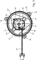
Figur 3 eine Draufsicht auf die Darstellung nachFigur 2 ; und -
Figur 4 eine Seitenansicht der Darstellung nachFigur 2 . -
Figur 1 zeigt eine schematische Darstellung eines erfindungsgemäßen Scheinwerfers 10 eines Kraftfahrzeugs mit einem Lichtmodul 12. Der Scheinwerfer 10 umfasst ein Gehäuse 14 mit einer durch eine Abdeckscheibe 16 verschlossenen Lichtaustrittsöffnung. Das Gehäuse 14 ist vorzugsweise aus Kunststoff gefertigt. Die Abdeckscheibe 16 besteht vorzugsweise aus einem transparenten Kunststoff oder Glas. Die Abdeckscheibe 16 kann als eine Streuscheibe zumindest teilweise mit optisch wirksamen Streuelementen (z.B. Prismen oder Zylinderlinsen) oder als eine klare Scheibe ohne solche Streuelemente ausgebildet sein. - Das Lichtmodul 12 ist in dem Gehäuse 14 angeordnet und dient zur Erzeugung einer vorgegebenen Lichtverteilung, beispielsweise einer Abblendlicht- oder Fernlichtverteilung oder einer beliebig anderen Lichtverteilung, bspw. einer adaptiven Lichtverteilung, vor dem Fahrzeug. Die Lichtverteilung ist durch Pfeile 17 symbolisiert. Das Lichtmodul 12 kann als ein Reflexionsmodul oder als ein Projektionsmodul ausgebildet sein. In dem Gehäuse 14 könnten auch noch weitere Lichtmodule zur Realisierung anderer Lichtfunktionen und/oder Leuchtenmodule zur Realisierung einer beliebigen Leuchtenfunktion, wie beispielsweise eines Blinklichts, eines Positionslichts und/oder eines Tagfahrlichts, angeordnet sein.
- Das Lichtmodul 12 weist mindestens eine Lichtquelle 18 zum Aussenden des Lichts zur Erzeugung der Lichtverteilung 17 auf, die in dem dargestellten Beispiel als eine Halbleiterlichtquelle, vorzugsweise als eine Leuchtdiode (LED), ausgebildet ist. Die Lichtquelle 18 könnte jedoch auch als eine Gasentladungslampe oder eine beliebig andere Lichtquelle ausgebildet sein. Zur Erzeugung der gewünschten Lichtverteilung 17 weist das Lichtmodul 12 üblicherweise eine Primäroptik, zum Beispiel in Form eines Reflektors und/oder einer TIR (Total Internal Reflection)-Vorsatzoptik, zum Bündeln des von der Halbleiterlichtquelle 18 ausgesandten Lichts auf (nicht dargestellt). Außerdem kann das Lichtmodul 12 auch eine Sekundäroptik (nicht dargestellt), zum Beispiel in Form einer Sammellinse, im Strahlengang des ausgesandten Lichts aufweisen, welche das gebündelte Licht zur Erzeugung der Lichtverteilung 17 auf die Fahrbahn vor das Fahrzeug projiziert. Falls die Lichtverteilung 17 eine abgeblendete Lichtverteilung (z.B. Abblendlicht, Nebellicht, etc.) ist, kann in dem Lichtmodul 12 zwischen der Primäroptik und der Sekundäroptik noch eine Blendenanordnung vorgesehen sein, deren Oberkante (bei vertikaler Blendenanordnung) bzw. Vorderkante (bei horizontaler Blendenanordnung) als Hell-Dunkel-Grenze auf die Fahrbahn vor das Fahrzeug projiziert wird.
- Das Lichtmodul 12 umfasst auch ein Trägerelement 20, auf dem die LED 18 angeordnet ist. Das Trägerelement 20 ist bspw. als eine Leiterplatte (PCB - Printed Circuit Board) ausgebildet. Die LED 18 ist auf dem Trägerelement 20 befestigt und über darauf ausgebildete Leiterbahnen kontaktiert. Es können auch mehrere LEDs 18 auf dem Trägerelement 20 angeordnet sein. Auch mehrere Trägerelemente 20 mit jeweils mindestens einer LED 18 können in dem Lichtmodul 12 vorgesehen sein. Das Trägerelement 20 ist zur besseren Wärmeabfuhr auf einem Kühlkörper 19 angeordnet. Dieser kann insbesondere nicht dargestellte oberflächenvergrößernde Elemente, beispielsweise in Form von Kühlrippen oder Kühlstiften, umfassen.
- Weiterhin umfasst das Gehäuse 14 eine Öffnung 22, beispielsweise an seiner Rückseite 24, wobei die Öffnung 22 von einem Befestigungsabschnitt 23 des Gehäuses 14 umgeben ist. Durch die Öffnung 22 ist ein elektrisch angetriebener Lüfter 26 in das Innere des Gehäuses 14 geführt. Weiterhin ist im Gehäuse 14 ein Stromteiler 28 vorgesehen, der über eine zentrale Stromzufuhr 30 mit elektrischer Energie versorgt wird. Der Stromteiler versorgt zum einen das Lichtmodul 12 mit elektrischer Energie über eine Stromzufuhr 32. Über eine Stromzufuhr 34, die durch die Innenseite des Gehäuses 14 geführt ist, wird zum anderen der Lüfter 26 ebenfalls mit elektrischer Energie versorgt.
- Der Lüfter 26 ist an einer Haltekappe 36 befestigt. Der detaillierte Aufbau dieser Anordnung wird im Folgenden anhand der
Figuren 2 bis 4 im Detail erläutert. Der Lüfter 26 umfasst zunächst einen im Wesentlichen rechteckigen Lüfterrahmen 38. Im Lüfterrahmen 38 ist zur Erzeugung eines Luftstroms ein Rotor 40 vorgesehen, der im Betrieb Luft im Inneren des Gehäuses 14 umwälzt und von einem nicht gezeigten elektrischen Motor antreibbar ist. - Die Haltekappe 36 umfasst zunächst einen kreiszylindrischen Übergangsabschnitt 42, der rohrförmig ausgebildet ist. Dieser liegt dicht an der Gehäuseöffnung 22 an, um insbesondere ein Eindringen von Verunreinigungen und/oder Feuchtigkeit zu verhindern. Dabei weist der Übergangsabschnitt 42 ein umlaufendes, im angeordneten Zustand dem Gehäuse 14 zugewandtes Ende 44 und ein umlaufendes, im angeordneten Zustand dem Gehäuse 14 abgewandtes Ende 46 auf. Im abgewandten Endbereich sind erfindungsgemäß drei zueinander versetzte Flanschabschnitte 48 vorgesehen. Diese ragen in radialer Richtung vom Übergangsabschnitt 42 ab und weisen eine Öffnung auf, um die Haltekappe 36 zusammen mit dem Lüfter 26, beispielsweise mittels einer Schraubverbindung, am Befestigungsabschnitt 23 des Gehäuses 14 zu befestigen. Auf der dem Gehäuse 14 abgewandten Seite 14 ist erfindungsgemäß ferner ein durchgehender plattenförmiger Halteabschnitt 50 befestigt, der die Haltekappe 36 nach außen verschließt. Dieser verhindert zudem zusammen mit dem Übergangsabschnitt 42 ein Eindringen von Verunreinigungen und/oder Feuchtigkeit in das Innere des Gehäuses 14. An der Außenseite des Halteabschnitts 50 ist ein Warnhinweis 51 angeordnet, um vor möglicher Strahlung im Inneren des Gehäuses 14 zu warnen. Der Halterahmen 38 und damit der Lüfter 26 als solches ist vom Halteabschnitt 50 beabstandet angeordnet. Hierzu weist die Haltekappe 36 zwei diagonal gegenüberliegende U-förmige Halter 56 auf. Um 90° dazu versetzt weist die Haltekappe 36 weiterhin zwei diagonal gegenüberliegende Befestigungselemente 58 in Form von Stiften auf, um den Lüfter 26 verliersicher am Halteabschnitt 50 zu befestigen. Dabei ist der Lüfter 26 vom Halteabschnitt 50 beabstandet angeordnet. Die U-förmigen Halter 56 weisen dabei an ihrer Oberseite 57 nicht gezeigte Rastnasen auf, die im eingebauten Zustand in komplementäre Aussparungen im Lüfter 26 eingreifen. Die U-förmigen Halter 56 umfassen bzw. bestehen aus einem formfesten aber elastischen Material. Dabei kann es sich beispielsweise um ein Elastomer, wie beispielsweise TPE, EPDM oder Silikon, handeln. Die Halter 56 sind damit weich aber formstabil. Dadurch können sie elastisch verformt werden, um die jeweilige Oberseite 57 zur Anordnung des Lüfters 26 auseinander zu biegen. Nach der Anordnung des Lüfters 26 liegen die Oberseiten 57 insbesondere unverformt am Lüfter 26 an, wobei die Rastnasen den Lüfter 26 verliersicher halten. Zusätzlich oder alternativ können auch die Befestigungsmittel 58 aus formfestem aber elastischem Material bestehen bzw. ein solches Material umfassen.
- Wenn die Haltekappe 36 am Gehäuse 14 angeordnet ist, ragt der Lüfter 26 durch den Übergangsabschnitt 42 und die Öffnung 22 hindurch in das Innere des Gehäuses 14 und erzeugt, wie in
Figur 4 durch die Pfeile 60 angedeutet, einen Kühlluftstrom im Inneren des Gehäuses 14 (durch eine Luftaustrittsöffnung 41 im Lüfterrahmen 38 hindurch, vgl.Figur 2 ), um das Lichtmodul 12 zu kühlen. Dabei wird Luft im Inneren des Gehäuses 14 umgewälzt. - Insgesamt ist die Funktionsweise des Scheinwerfers 10 wie folgt:
Im Betrieb des Lüfters 26 wird der Rotor 40 rotiert, um Luft im Inneren des Gehäuses 14 umzuwälzen, sodass ein Kühlluftstrom erzeugt werden kann. Dieser dient zur Kühlung des Lichtmoduls 12, insbesondere des Kühlkörpers 19. Beim Betreiben des Lüfters 26 können mechanische Schwingungen auftreten. Treten derartige Schwingungen auf, so werden diese nicht oder lediglich mit verringerter Schwingungsamplitude auf das Gehäuse 14 übertragen. Dabei trägt der Aufbau der Haltekappe 36 insgesamt zur Dämpfung bei, so dass mechanische Schwingungsenergie, insbesondere durch eine elastische Verformung, in insbesondere Wärmeenergie umgewandelt wird. Diese dämpfende Eigenschaft kann zum einen durch eine geeignete Werkstoffauswahl erzielt werden. Dabei kann die Haltekappe 36 insgesamt oder abschnittsweise aus einem Werkstoff mit gegenüber dem Gehäuse 14 verringerter Steifigkeit bzw. Härte aufgebaut sein. Geeignet wäre beispielsweise Schaumstoff, insbesondere Hartschaumstoff, oder ein Elastomer, wie beispielsweise TDE, EPDM oder Silikon. Denkbar wäre auch, dass sämtliche oder jedenfalls einige aneinander angrenzende Bauteilkomponenten aus unterschiedlichen Werkstoffen aufgebaut sind. Es hat sich herausgestellt, dass dies zur Schwingungsdämpfung positiv beitragen kann. Insbesondere die Ausbildung der Befestigungsmittel 56 und/oder 58 aus formfestem aber elastischem Material, beispielsweise einem Elastomer, wie beispielsweise TDE, EPDM oder Silikon, ermöglicht eine positive Schwingungsdämpfung. - Weiterhin trägt die strukturelle Ausgestaltung, insbesondere die geometrische Form, zur Schwingungsdämpfung bei. Insbesondere die die Beabstandung des Lüfters 26 zum Befestigungsabschnitt 42 kann eine Reduktion der Schwingungsamplituden, die insbesondere im Lüfter 26 erzeugt werden können, bewirken.
- Insgesamt kann erfindungsgemäß eine mechanische Entkopplung zwischen Gehäuse 14 und Lüfter 26 bereitgestellt werden. Insbesondere können Schallübertragungen vom Lüfter 26 über das Gehäuse 14 in das Fahrzeug(innere) jedenfalls verringert werden. Weiterhin kann die mechanische Belastung durch Schwingungen reduziert werden, so dass eine mechanische Beschädigung in Form von Abrieb und/oder mechanischem Spiel reduziert ist. Somit kann zum einen eine Geräuschreduktion und zum anderen eine Verschleißreduktion bereitgestellt werden.
Claims (11)
- Kraftfahrzeugscheinwerfer (10) mit einem Gehäuse (14) und einer Gehäuseöffnung (22), wobei eine die Gehäuseöffnung (22) abdeckende Haltekappe (36) vorgesehen ist, wobei die Haltekappe (36) einen Halteabschnitt (50), an dem ein elektrisch angetriebener Lüfter (26) befestigt ist, aufweist, wobei die Haltekappe (36) einen kreiszylindrischen Übergangsabschnitt (42) aufweist, der rohrförmig ausgebildet ist und der ein umlaufendes, dem Gehäuse (14) zugewandtes Ende (44) und ein umlaufendes, dem Gehäuse (14) abgewandtes Ende (46) aufweist, dadurch gekennzeichnet, dass drei zueinander versetzte Flanschabschnitte (48) vorgesehen sind, die in radialer Richtung vom Übergangsabschnitt (42) ab ragen und die eine Öffnung aufweisen, um die Haltekappe (36) zusammen mit dem Lüfter (26) an einem Befestigungsabschnitt (23) des Gehäuses (14) zu befestigen, wobei der Halteabschnitt (50) als ein plattenförmiger Halteabschnitt ausgebildet ist, welcher auf der dem Gehäuse (14) abgewandten Seite befestigt ist und die Haltekappe (36) nach außen verschließt, wobei der Lüfter (26) durch die Gehäuseöffnung (22) in einen Innenraum des Gehäuses (14) geführt ist, wobei die Haltekappe (36) und der Befestigungsabschnitt (23) des Gehäuses (14), an dem die Haltekappe (36) befestigt ist, durch ihre Materialzusammensetzung und durch ihre strukturelle Ausbildung dazu eingerichtet sind, eine Übertragung mechanischer Schwingungen zwischen dem Lüfter (26) und dem Gehäuse (14) zu dämpfen, wobei der Lüfter (26) einen Lüfterrahmen (38) aufweist, wobei die Haltekappe (36) Befestigungsmittel (56, 58) aufweist, und wobei der Lüfterrahmen (38) mit den Befestigungsmitteln (56, 58) am Halteabschnitt (50) so befestigt ist, dass der Lüfter (26) vom Halteabschnitt (50) beabstandet ist.
- Kraftfahrzeugscheinwerfer (10) nach Anspruch 1, wobei die Haltekappe (36) und der Befestigungsabschnitt (23) des Gehäuses (14), an dem die Haltekappe (36) befestigt ist, jedenfalls abschnittsweise Materialien unterschiedlicher Steifigkeit aufweisen.
- Kraftfahrzeugscheinwerfer (10) nach einem der vorhergehenden Ansprüche, wobei die Haltekappe (36) wenigstens abschnittsweise eine geringere Steifigkeit als der Befestigungsabschnitt (23) des Gehäuses (14), an dem die Haltekappe (36) befestigt ist, aufweist.
- Kraftfahrzeugscheinwerfer (10) nach einem der vorhergehenden Ansprüche, wobei die Haltekappe (36) einen Übergangsabschnitt (42) zwischen den Flanschabschnitten (48) und dem Halteabschnitt (50) umfasst.
- Kraftfahrzeugscheinwerfer (10) nach Anspruch 4, dadurch gekennzeichnet, dass der Übergangsabschnitt (42) und der Halteabschnitt (50) und/oder der Übergangsabschnitt (42) und der Flanschabschnitt (48) wenigstens abschnittsweise eine unterschiedliche Steifigkeit aufweisen.
- Kraftfahrzeugscheinwerfer (10) nach einem der vorhergehenden Ansprüche 4 bis 6, wobei der Übergangsabschnitt (42) zylindrisch ausgebildet ist, wobei der Halteabschnitt (50) an einem der Öffnung (22) abgewandten Ende (46) des Übergangsabschnitts (42) angeordnet ist.
- Kraftfahrzeugscheinwerfer (10) nach einem der vorhergehenden Ansprüche, wobei die Haltekappe (36) jedenfalls abschnittsweise aus einem formfesten, elastischen Material, insbesondere aus einem Elastomer, besteht.
- Kraftfahrzeugscheinwerfer (10) nach den Ansprüchen 6 und 8, wobei die Befestigungsmittel (56, 58) aus dem formfesten, elastischen Material, insbesondere aus einem Elastomer, bestehen.
- Kraftfahrzeugscheinwerfer (10) nach einem der vorhergehenden Ansprüche 4 bis 9, wobei der Flanschabschnitt (48) an einem der Öffnung (22) abgewandten Endbereich des Übergangsabschnitts (42) vorgesehen ist.
- Kraftfahrzeugscheinwerfer (10) nach einem der vorhergehenden Ansprüche, wobei die Gehäuseöffnung (22) auf einer Lichtaustrittsöffnung des Gehäuses (14) abgewandten Rückseite des Gehäuses (14) vorgesehen ist.
- Kraftfahrzeugscheinwerfer (10) nach einem der vorhergehenden Ansprüche 4 bis 11, wobei der Übergangsabschnitt (42) dicht an der Gehäuseöffnung (22) anliegt.
Applications Claiming Priority (1)
| Application Number | Priority Date | Filing Date | Title |
|---|---|---|---|
| DE102018124098.8A DE102018124098A1 (de) | 2018-09-28 | 2018-09-28 | Kraftfahrzeugscheinwerfer mit Lüfter |
Publications (2)
| Publication Number | Publication Date |
|---|---|
| EP3628917A1 EP3628917A1 (de) | 2020-04-01 |
| EP3628917B1 true EP3628917B1 (de) | 2023-01-04 |
Family
ID=67847592
Family Applications (1)
| Application Number | Title | Priority Date | Filing Date |
|---|---|---|---|
| EP19195012.0A Active EP3628917B1 (de) | 2018-09-28 | 2019-09-03 | Kraftfahrzeugscheinwerfer mit lüfter |
Country Status (2)
| Country | Link |
|---|---|
| EP (1) | EP3628917B1 (de) |
| DE (1) | DE102018124098A1 (de) |
Families Citing this family (3)
| Publication number | Priority date | Publication date | Assignee | Title |
|---|---|---|---|---|
| DE102020112963B3 (de) | 2020-05-13 | 2021-10-07 | HELLA GmbH & Co. KGaA | Lüftersystem für einen Scheinwerfer eines Kraftfahrzeugs, Scheinwerfer und Kraftfahrzeug |
| CN113202714A (zh) * | 2021-04-15 | 2021-08-03 | 恒大恒驰新能源汽车研究院(上海)有限公司 | 照明装置、散热组件及驱动泵 |
| DE102023211002A1 (de) * | 2023-11-07 | 2025-05-08 | Marelli Automotive Lighting Reutlingen (Germany) GmbH | Kraftfahrzeugscheinwerfer und Kraftfahrzeug |
Family Cites Families (9)
| Publication number | Priority date | Publication date | Assignee | Title |
|---|---|---|---|---|
| DE19712228B4 (de) * | 1997-03-24 | 2006-04-13 | Behr Gmbh & Co. Kg | Befestigungsvorrichtung für einen Gebläsemotor |
| JP2004253325A (ja) * | 2003-02-21 | 2004-09-09 | Kanto Auto Works Ltd | 車両のヘッドランプ |
| KR100923140B1 (ko) * | 2007-12-18 | 2009-10-23 | 에스엘 주식회사 | Led방열 장치 |
| JP2010262903A (ja) * | 2009-05-11 | 2010-11-18 | Koito Mfg Co Ltd | 車両用灯具 |
| JP2011048923A (ja) * | 2009-08-25 | 2011-03-10 | Stanley Electric Co Ltd | 車両用灯具 |
| DE202009015068U1 (de) * | 2009-11-05 | 2011-03-24 | Ebm-Papst St. Georgen Gmbh & Co. Kg | Lüfteranordnung |
| DE102011004746B4 (de) * | 2011-02-25 | 2023-09-28 | Osram Gmbh | Halbleiter-Leuchtmodul und Fahrzeugleuchte |
| KR20140029022A (ko) * | 2012-08-31 | 2014-03-10 | 에스엘 주식회사 | 차량용 램프의 냉각장치 |
| DE102012111638B4 (de) * | 2012-11-30 | 2023-03-16 | HELLA GmbH & Co. KGaA | Beleuchtungssystem für ein Kraftfahrzeug |
-
2018
- 2018-09-28 DE DE102018124098.8A patent/DE102018124098A1/de not_active Withdrawn
-
2019
- 2019-09-03 EP EP19195012.0A patent/EP3628917B1/de active Active
Also Published As
| Publication number | Publication date |
|---|---|
| EP3628917A1 (de) | 2020-04-01 |
| DE102018124098A1 (de) | 2020-04-02 |
Similar Documents
| Publication | Publication Date | Title |
|---|---|---|
| EP3628917B1 (de) | Kraftfahrzeugscheinwerfer mit lüfter | |
| EP2800677B1 (de) | Standardlichtquelle laser-diode | |
| DE102011079216A1 (de) | Träger für ein Displaymodul und Anzeigevorrichtung mit einem derartigen Träger | |
| DE102015106708B4 (de) | Vorrichtung zur Emission von Licht, insbesondere zur Erzeugung eines Bildes | |
| DE102008061526A1 (de) | Fahrzeugscheinwerfer | |
| DE112010005720T5 (de) | Lichtquellen-Anschaltgerät für Scheinwerfer | |
| DE102012215711A1 (de) | Fahrzeugbeleuchtungsvorrichtung | |
| DE102008016301A1 (de) | Scheinwerferbaugruppe mit isolierter optischer Kammer | |
| DE102017214668A1 (de) | Fassung mit bewegbar gelagerter Optik | |
| DE102009021353A1 (de) | Scheinwerfer | |
| DE102009023645A1 (de) | LED-Modul | |
| DE102011053551A1 (de) | Scheinwerfer für ein Fahrzeug | |
| DE202020101383U1 (de) | Beleuchtungsvorrichtung mit Adapterring | |
| DE10227720A1 (de) | LED-Scheinwerfer | |
| EP3861244A1 (de) | Kraftfahrzeugscheinwerfer und lüfter hierfür | |
| DE102007000571A1 (de) | Entladungslampenaufbau mit Steuereinheit | |
| DE102013108248A1 (de) | Beleuchtungssystem, insbesondere für einen Kraftfahrzeugscheinwerfer mit einem Kühlkörper | |
| DE102017104699A1 (de) | Laseroszillator | |
| WO2012113705A2 (de) | Beleuchtungseinrichtung | |
| DE102008030353B4 (de) | Fahrzeugleuchte mit einem Wärme leitenden Kunststoff | |
| DE102014105099A1 (de) | Beleuchtungsvorrichtung für Fahrzeuge | |
| EP3010320A1 (de) | Vorrichtung zur Kühlung einer elektronischen Steuereinheit und Steuergerät | |
| DE102018008828B4 (de) | Gerät | |
| DE102021005388B4 (de) | Schweinwerfer mit einem Kühlmodul | |
| DE102019006275A1 (de) | Vorrichtung zur Bestrahlung einer Fläche |
Legal Events
| Date | Code | Title | Description |
|---|---|---|---|
| PUAI | Public reference made under article 153(3) epc to a published international application that has entered the european phase |
Free format text: ORIGINAL CODE: 0009012 |
|
| STAA | Information on the status of an ep patent application or granted ep patent |
Free format text: STATUS: THE APPLICATION HAS BEEN PUBLISHED |
|
| AK | Designated contracting states |
Kind code of ref document: A1 Designated state(s): AL AT BE BG CH CY CZ DE DK EE ES FI FR GB GR HR HU IE IS IT LI LT LU LV MC MK MT NL NO PL PT RO RS SE SI SK SM TR |
|
| AX | Request for extension of the european patent |
Extension state: BA ME |
|
| STAA | Information on the status of an ep patent application or granted ep patent |
Free format text: STATUS: REQUEST FOR EXAMINATION WAS MADE |
|
| 17P | Request for examination filed |
Effective date: 20200930 |
|
| RBV | Designated contracting states (corrected) |
Designated state(s): AL AT BE BG CH CY CZ DE DK EE ES FI FR GB GR HR HU IE IS IT LI LT LU LV MC MK MT NL NO PL PT RO RS SE SI SK SM TR |
|
| GRAP | Despatch of communication of intention to grant a patent |
Free format text: ORIGINAL CODE: EPIDOSNIGR1 |
|
| STAA | Information on the status of an ep patent application or granted ep patent |
Free format text: STATUS: GRANT OF PATENT IS INTENDED |
|
| INTG | Intention to grant announced |
Effective date: 20220712 |
|
| GRAS | Grant fee paid |
Free format text: ORIGINAL CODE: EPIDOSNIGR3 |
|
| RIN1 | Information on inventor provided before grant (corrected) |
Inventor name: GOTTWALLES, HUBERT NICOLAS Inventor name: HAHN, CHRISTOPH Inventor name: MUELLER, MARCUS Inventor name: OTTO, CARSTEN |
|
| GRAA | (expected) grant |
Free format text: ORIGINAL CODE: 0009210 |
|
| STAA | Information on the status of an ep patent application or granted ep patent |
Free format text: STATUS: THE PATENT HAS BEEN GRANTED |
|
| AK | Designated contracting states |
Kind code of ref document: B1 Designated state(s): AL AT BE BG CH CY CZ DE DK EE ES FI FR GB GR HR HU IE IS IT LI LT LU LV MC MK MT NL NO PL PT RO RS SE SI SK SM TR |
|
| REG | Reference to a national code |
Ref country code: GB Ref legal event code: FG4D Free format text: NOT ENGLISH |
|
| REG | Reference to a national code |
Ref country code: DE Ref legal event code: R096 Ref document number: 502019006678 Country of ref document: DE |
|
| REG | Reference to a national code |
Ref country code: CH Ref legal event code: EP |
|
| REG | Reference to a national code |
Ref country code: AT Ref legal event code: REF Ref document number: 1542178 Country of ref document: AT Kind code of ref document: T Effective date: 20230115 |
|
| REG | Reference to a national code |
Ref country code: IE Ref legal event code: FG4D Free format text: LANGUAGE OF EP DOCUMENT: GERMAN |
|
| REG | Reference to a national code |
Ref country code: LT Ref legal event code: MG9D |
|
| REG | Reference to a national code |
Ref country code: NL Ref legal event code: MP Effective date: 20230104 |
|
| PG25 | Lapsed in a contracting state [announced via postgrant information from national office to epo] |
Ref country code: NL Free format text: LAPSE BECAUSE OF FAILURE TO SUBMIT A TRANSLATION OF THE DESCRIPTION OR TO PAY THE FEE WITHIN THE PRESCRIBED TIME-LIMIT Effective date: 20230104 |
|
| PG25 | Lapsed in a contracting state [announced via postgrant information from national office to epo] |
Ref country code: RS Free format text: LAPSE BECAUSE OF FAILURE TO SUBMIT A TRANSLATION OF THE DESCRIPTION OR TO PAY THE FEE WITHIN THE PRESCRIBED TIME-LIMIT Effective date: 20230104 Ref country code: PT Free format text: LAPSE BECAUSE OF FAILURE TO SUBMIT A TRANSLATION OF THE DESCRIPTION OR TO PAY THE FEE WITHIN THE PRESCRIBED TIME-LIMIT Effective date: 20230504 Ref country code: NO Free format text: LAPSE BECAUSE OF FAILURE TO SUBMIT A TRANSLATION OF THE DESCRIPTION OR TO PAY THE FEE WITHIN THE PRESCRIBED TIME-LIMIT Effective date: 20230404 Ref country code: LV Free format text: LAPSE BECAUSE OF FAILURE TO SUBMIT A TRANSLATION OF THE DESCRIPTION OR TO PAY THE FEE WITHIN THE PRESCRIBED TIME-LIMIT Effective date: 20230104 Ref country code: LT Free format text: LAPSE BECAUSE OF FAILURE TO SUBMIT A TRANSLATION OF THE DESCRIPTION OR TO PAY THE FEE WITHIN THE PRESCRIBED TIME-LIMIT Effective date: 20230104 Ref country code: HR Free format text: LAPSE BECAUSE OF FAILURE TO SUBMIT A TRANSLATION OF THE DESCRIPTION OR TO PAY THE FEE WITHIN THE PRESCRIBED TIME-LIMIT Effective date: 20230104 Ref country code: ES Free format text: LAPSE BECAUSE OF FAILURE TO SUBMIT A TRANSLATION OF THE DESCRIPTION OR TO PAY THE FEE WITHIN THE PRESCRIBED TIME-LIMIT Effective date: 20230104 |
|
| PG25 | Lapsed in a contracting state [announced via postgrant information from national office to epo] |
Ref country code: SE Free format text: LAPSE BECAUSE OF FAILURE TO SUBMIT A TRANSLATION OF THE DESCRIPTION OR TO PAY THE FEE WITHIN THE PRESCRIBED TIME-LIMIT Effective date: 20230104 Ref country code: PL Free format text: LAPSE BECAUSE OF FAILURE TO SUBMIT A TRANSLATION OF THE DESCRIPTION OR TO PAY THE FEE WITHIN THE PRESCRIBED TIME-LIMIT Effective date: 20230104 Ref country code: IS Free format text: LAPSE BECAUSE OF FAILURE TO SUBMIT A TRANSLATION OF THE DESCRIPTION OR TO PAY THE FEE WITHIN THE PRESCRIBED TIME-LIMIT Effective date: 20230504 Ref country code: GR Free format text: LAPSE BECAUSE OF FAILURE TO SUBMIT A TRANSLATION OF THE DESCRIPTION OR TO PAY THE FEE WITHIN THE PRESCRIBED TIME-LIMIT Effective date: 20230405 Ref country code: FI Free format text: LAPSE BECAUSE OF FAILURE TO SUBMIT A TRANSLATION OF THE DESCRIPTION OR TO PAY THE FEE WITHIN THE PRESCRIBED TIME-LIMIT Effective date: 20230104 |
|
| REG | Reference to a national code |
Ref country code: DE Ref legal event code: R097 Ref document number: 502019006678 Country of ref document: DE |
|
| PG25 | Lapsed in a contracting state [announced via postgrant information from national office to epo] |
Ref country code: SM Free format text: LAPSE BECAUSE OF FAILURE TO SUBMIT A TRANSLATION OF THE DESCRIPTION OR TO PAY THE FEE WITHIN THE PRESCRIBED TIME-LIMIT Effective date: 20230104 Ref country code: RO Free format text: LAPSE BECAUSE OF FAILURE TO SUBMIT A TRANSLATION OF THE DESCRIPTION OR TO PAY THE FEE WITHIN THE PRESCRIBED TIME-LIMIT Effective date: 20230104 Ref country code: EE Free format text: LAPSE BECAUSE OF FAILURE TO SUBMIT A TRANSLATION OF THE DESCRIPTION OR TO PAY THE FEE WITHIN THE PRESCRIBED TIME-LIMIT Effective date: 20230104 Ref country code: DK Free format text: LAPSE BECAUSE OF FAILURE TO SUBMIT A TRANSLATION OF THE DESCRIPTION OR TO PAY THE FEE WITHIN THE PRESCRIBED TIME-LIMIT Effective date: 20230104 Ref country code: CZ Free format text: LAPSE BECAUSE OF FAILURE TO SUBMIT A TRANSLATION OF THE DESCRIPTION OR TO PAY THE FEE WITHIN THE PRESCRIBED TIME-LIMIT Effective date: 20230104 |
|
| PLBE | No opposition filed within time limit |
Free format text: ORIGINAL CODE: 0009261 |
|
| STAA | Information on the status of an ep patent application or granted ep patent |
Free format text: STATUS: NO OPPOSITION FILED WITHIN TIME LIMIT |
|
| PG25 | Lapsed in a contracting state [announced via postgrant information from national office to epo] |
Ref country code: SK Free format text: LAPSE BECAUSE OF FAILURE TO SUBMIT A TRANSLATION OF THE DESCRIPTION OR TO PAY THE FEE WITHIN THE PRESCRIBED TIME-LIMIT Effective date: 20230104 |
|
| 26N | No opposition filed |
Effective date: 20231005 |
|
| PG25 | Lapsed in a contracting state [announced via postgrant information from national office to epo] |
Ref country code: SI Free format text: LAPSE BECAUSE OF FAILURE TO SUBMIT A TRANSLATION OF THE DESCRIPTION OR TO PAY THE FEE WITHIN THE PRESCRIBED TIME-LIMIT Effective date: 20230104 |
|
| REG | Reference to a national code |
Ref country code: CH Ref legal event code: PL |
|
| PG25 | Lapsed in a contracting state [announced via postgrant information from national office to epo] |
Ref country code: LU Free format text: LAPSE BECAUSE OF NON-PAYMENT OF DUE FEES Effective date: 20230903 |
|
| REG | Reference to a national code |
Ref country code: BE Ref legal event code: MM Effective date: 20230930 |
|
| GBPC | Gb: european patent ceased through non-payment of renewal fee |
Effective date: 20230903 |
|
| PG25 | Lapsed in a contracting state [announced via postgrant information from national office to epo] |
Ref country code: LU Free format text: LAPSE BECAUSE OF NON-PAYMENT OF DUE FEES Effective date: 20230903 Ref country code: IT Free format text: LAPSE BECAUSE OF FAILURE TO SUBMIT A TRANSLATION OF THE DESCRIPTION OR TO PAY THE FEE WITHIN THE PRESCRIBED TIME-LIMIT Effective date: 20230104 Ref country code: MC Free format text: LAPSE BECAUSE OF FAILURE TO SUBMIT A TRANSLATION OF THE DESCRIPTION OR TO PAY THE FEE WITHIN THE PRESCRIBED TIME-LIMIT Effective date: 20230104 |
|
| REG | Reference to a national code |
Ref country code: IE Ref legal event code: MM4A |
|
| PG25 | Lapsed in a contracting state [announced via postgrant information from national office to epo] |
Ref country code: IE Free format text: LAPSE BECAUSE OF NON-PAYMENT OF DUE FEES Effective date: 20230903 |
|
| PG25 | Lapsed in a contracting state [announced via postgrant information from national office to epo] |
Ref country code: GB Free format text: LAPSE BECAUSE OF NON-PAYMENT OF DUE FEES Effective date: 20230903 |
|
| PG25 | Lapsed in a contracting state [announced via postgrant information from national office to epo] |
Ref country code: CH Free format text: LAPSE BECAUSE OF NON-PAYMENT OF DUE FEES Effective date: 20230930 |
|
| PG25 | Lapsed in a contracting state [announced via postgrant information from national office to epo] |
Ref country code: IE Free format text: LAPSE BECAUSE OF NON-PAYMENT OF DUE FEES Effective date: 20230903 Ref country code: GB Free format text: LAPSE BECAUSE OF NON-PAYMENT OF DUE FEES Effective date: 20230903 Ref country code: FR Free format text: LAPSE BECAUSE OF NON-PAYMENT OF DUE FEES Effective date: 20230930 Ref country code: CH Free format text: LAPSE BECAUSE OF NON-PAYMENT OF DUE FEES Effective date: 20230930 |
|
| PG25 | Lapsed in a contracting state [announced via postgrant information from national office to epo] |
Ref country code: BE Free format text: LAPSE BECAUSE OF NON-PAYMENT OF DUE FEES Effective date: 20230930 |
|
| PG25 | Lapsed in a contracting state [announced via postgrant information from national office to epo] |
Ref country code: BG Free format text: LAPSE BECAUSE OF FAILURE TO SUBMIT A TRANSLATION OF THE DESCRIPTION OR TO PAY THE FEE WITHIN THE PRESCRIBED TIME-LIMIT Effective date: 20230104 |
|
| PG25 | Lapsed in a contracting state [announced via postgrant information from national office to epo] |
Ref country code: BG Free format text: LAPSE BECAUSE OF FAILURE TO SUBMIT A TRANSLATION OF THE DESCRIPTION OR TO PAY THE FEE WITHIN THE PRESCRIBED TIME-LIMIT Effective date: 20230104 |
|
| REG | Reference to a national code |
Ref country code: DE Ref legal event code: R084 Ref document number: 502019006678 Country of ref document: DE |
|
| PG25 | Lapsed in a contracting state [announced via postgrant information from national office to epo] |
Ref country code: CY Free format text: LAPSE BECAUSE OF FAILURE TO SUBMIT A TRANSLATION OF THE DESCRIPTION OR TO PAY THE FEE WITHIN THE PRESCRIBED TIME-LIMIT; INVALID AB INITIO Effective date: 20190903 |
|
| PG25 | Lapsed in a contracting state [announced via postgrant information from national office to epo] |
Ref country code: HU Free format text: LAPSE BECAUSE OF FAILURE TO SUBMIT A TRANSLATION OF THE DESCRIPTION OR TO PAY THE FEE WITHIN THE PRESCRIBED TIME-LIMIT; INVALID AB INITIO Effective date: 20190903 |
|
| PGFP | Annual fee paid to national office [announced via postgrant information from national office to epo] |
Ref country code: DE Payment date: 20250820 Year of fee payment: 7 |
|
| REG | Reference to a national code |
Ref country code: AT Ref legal event code: MM01 Ref document number: 1542178 Country of ref document: AT Kind code of ref document: T Effective date: 20240903 |
|
| PG25 | Lapsed in a contracting state [announced via postgrant information from national office to epo] |
Ref country code: TR Free format text: LAPSE BECAUSE OF FAILURE TO SUBMIT A TRANSLATION OF THE DESCRIPTION OR TO PAY THE FEE WITHIN THE PRESCRIBED TIME-LIMIT Effective date: 20230104 |
|
| PG25 | Lapsed in a contracting state [announced via postgrant information from national office to epo] |
Ref country code: AT Free format text: LAPSE BECAUSE OF NON-PAYMENT OF DUE FEES Effective date: 20240903 |
|
| REG | Reference to a national code |
Ref country code: DE Ref legal event code: R081 Ref document number: 502019006678 Country of ref document: DE Owner name: MARELLI GERMANY GMBH, DE Free format text: FORMER OWNER: AUTOMOTIVE LIGHTING REUTLINGEN GMBH, 72762 REUTLINGEN, DE |
|
| PGFP | Annual fee paid to national office [announced via postgrant information from national office to epo] |
Ref country code: AT Payment date: 20260410 Year of fee payment: 5 |