EP3628781A1 - Verfahren zum herstellen eines injektionsankers im boden und nachverpressautomat hierfür - Google Patents
Verfahren zum herstellen eines injektionsankers im boden und nachverpressautomat hierfür Download PDFInfo
- Publication number
- EP3628781A1 EP3628781A1 EP18196794.4A EP18196794A EP3628781A1 EP 3628781 A1 EP3628781 A1 EP 3628781A1 EP 18196794 A EP18196794 A EP 18196794A EP 3628781 A1 EP3628781 A1 EP 3628781A1
- Authority
- EP
- European Patent Office
- Prior art keywords
- injection
- post
- medium
- anchor
- anchor foot
- Prior art date
- Legal status (The legal status is an assumption and is not a legal conclusion. Google has not performed a legal analysis and makes no representation as to the accuracy of the status listed.)
- Granted
Links
Images
Classifications
-
- E—FIXED CONSTRUCTIONS
- E02—HYDRAULIC ENGINEERING; FOUNDATIONS; SOIL SHIFTING
- E02D—FOUNDATIONS; EXCAVATIONS; EMBANKMENTS; UNDERGROUND OR UNDERWATER STRUCTURES
- E02D5/00—Bulkheads, piles, or other structural elements specially adapted to foundation engineering
- E02D5/74—Means for anchoring structural elements or bulkheads
- E02D5/80—Ground anchors
- E02D5/808—Ground anchors anchored by using exclusively a bonding material
-
- E—FIXED CONSTRUCTIONS
- E02—HYDRAULIC ENGINEERING; FOUNDATIONS; SOIL SHIFTING
- E02D—FOUNDATIONS; EXCAVATIONS; EMBANKMENTS; UNDERGROUND OR UNDERWATER STRUCTURES
- E02D5/00—Bulkheads, piles, or other structural elements specially adapted to foundation engineering
- E02D5/74—Means for anchoring structural elements or bulkheads
-
- E—FIXED CONSTRUCTIONS
- E02—HYDRAULIC ENGINEERING; FOUNDATIONS; SOIL SHIFTING
- E02D—FOUNDATIONS; EXCAVATIONS; EMBANKMENTS; UNDERGROUND OR UNDERWATER STRUCTURES
- E02D5/00—Bulkheads, piles, or other structural elements specially adapted to foundation engineering
- E02D5/74—Means for anchoring structural elements or bulkheads
- E02D5/76—Anchorings for bulkheads or sections thereof in as much as specially adapted therefor
-
- E—FIXED CONSTRUCTIONS
- E02—HYDRAULIC ENGINEERING; FOUNDATIONS; SOIL SHIFTING
- E02D—FOUNDATIONS; EXCAVATIONS; EMBANKMENTS; UNDERGROUND OR UNDERWATER STRUCTURES
- E02D5/00—Bulkheads, piles, or other structural elements specially adapted to foundation engineering
- E02D5/74—Means for anchoring structural elements or bulkheads
- E02D5/80—Ground anchors
-
- E—FIXED CONSTRUCTIONS
- E02—HYDRAULIC ENGINEERING; FOUNDATIONS; SOIL SHIFTING
- E02D—FOUNDATIONS; EXCAVATIONS; EMBANKMENTS; UNDERGROUND OR UNDERWATER STRUCTURES
- E02D2250/00—Production methods
- E02D2250/003—Injection of material
Definitions
- the invention relates to a method for producing an injection anchor in the ground, wherein a hole is made in the ground, a hardening compound is injected at least in a partial region of the hole to form an anchor foot by means of an injection member, and after a partial, not yet complete hardening of the compound In a region of the anchor foot, a post-injection medium is introduced under pressure via a post-injection member, by means of which the anchor foot, which has not yet fully hardened, is broken open, according to the preamble of claim 1.
- the invention further relates to an automatic repressing machine for such a method according to claim 9.
- an injection anchor also called anchoring anchor
- anchoring anchor with an enlarged anchor base.
- a hole is made in the floor into which a tension member for the anchor is inserted.
- An anchor foot is formed in the ground in an anchoring area of the tension member by injecting hardening building material.
- an injection pipe which is introduced into the bore together with the tension member, further hardening building material is pressed into the anchoring area under high pressure before the anchor foot is completely hardened by the injection pipe.
- the primary anchor foot created and partially hardened in the first step is broken up and can thus be expanded, in particular in the radial direction, to form a secondary anchor foot, by means of which a stronger anchoring of the tension member can be achieved.
- the anchor foot is usually produced on construction sites on a first day, while the subsequent pressing is then carried out by tearing open the anchor foot on the following day.
- grout anchors are usually manufactured on a construction site from Monday to Thursday during a working week, with the grouting being carried out on the following day.
- injection anchors with primary anchor feet are no longer created on a Friday, since it is not or hardly possible to carry out the re-grouting until the following Monday, due to the advanced hardening of the anchor foot could no longer be reliably broken open by a re-injection medium.
- the invention is based on the object of specifying a method for producing an injection anchor in the ground and a device therefor, in which there is increased time flexibility in the manufacture of injection anchors.
- the object is achieved on the one hand by a method with the features of claim 1 and on the other hand with a post-injection machine with the features of claim 9.
- Preferred embodiments of the invention are specified in the respective dependent claims.
- the method according to the invention is characterized in that a post-injection machine is connected to the post-injection member, through which the post-injection medium is automatically introduced into the post-injection member at a freely definable point in time for breaking up the not yet fully hardened anchor foot.
- a basic idea of the invention is that an anchor foot can be repressed without personnel by a special automatic repressing machine.
- the post-injection machine is pipeline-connected to the post-injection member, and the post-injection medium can be automatically introduced into the post-injection member to break open the primary anchor foot, which has not yet hardened. Any time can be entered in the post-injection machine at which the post-injection medium is then introduced into the post-injection member.
- the time for repressing can also be switched from a remote control center via a preferably wireless data connection or depending on sensors which determine, for example, a state of the primary anchor foot, such as strength or residual moisture etc., the environment or other relevant parameters.
- a tension member for the anchor is introduced into or after the hole has been drilled into it, it being necessary to ensure that the tension member is reliably connected to the anchor foot formed.
- a preferred embodiment of the invention consists in the fact that the post-injection medium is a liquid, in particular water, or a gas, in particular compressed air, through which the anchor foot is broken open and that a hardenable medium is introduced into the broken anchor foot at intervals.
- the primary anchor foot is first broken open by a non-hardening medium, in particular water or compressed air, at the specified point in time. This first step can be carried out by the post-injection machine, the storage of water or compressed air, which is formed in particular from the ambient air, being possible without any problems.
- the second step of repressing by introducing a hardening medium into the broken primary anchor foot can either also be carried out by the repressing machine, which then has an additional memory and, if appropriate, an additional printing device for generating the pressure for the hardenable medium.
- the second step of repressing cannot be carried out automatically by personnel at a later point in time. After the primary anchor foot has been broken open, the broken anchor foot parts can harden themselves until the hardening medium is introduced.
- a hardenable medium is used as the secondary injection medium, in particular the hardening mass for forming the anchor foot.
- the post-grouting is therefore carried out in a single step, the post-grouting medium in particular being a cement suspension or another curable suspension.
- the invention encompasses all of these basic method variants for producing an injection anchor, but with the step of automatic repressing.
- the injection member for injecting the curable composition and a separate post-injection member for injecting the post-injection medium remain in the bore.
- the injection member and the secondary injection member can advantageously be introduced into the bore together with the tension member.
- the injection member could also be used as a post-injection member for the post-injection medium and / or another hardenable medium for forming the secondary anchor foot.
- the injection member can be a separate element which is introduced into the bore with or after the removal of the drilling tool.
- the injection member is designed as a drilling tool with which the hole is made in the ground.
- the injection member can simultaneously or alternatively be part of the tension member, so that an overall simple workflow is achieved.
- a particularly expedient variant of the method also consists in the fact that the post-injection member has at least one outlet opening through which the post-injection medium is introduced into the bore.
- the hose-like or tube-like post-compression member can have a section in the region of the anchor foot to be formed with a plurality of openings or with a reduced material thickness, which tears open in a defined manner when the post-compression medium is introduced.
- the post-injection medium can escape into the surrounding area and break open the primary anchor foot or introduce a hardenable medium to form the secondary anchor foot.
- a suitable pressure is set.
- the post-injection machine is provided with a control in which a time for executing the automatic post-injection is entered.
- the controller can in particular have a timer, with which in particular a time span or a defined point in time for carrying out the automatic repressing can be entered.
- the mechanical or preferably electronic control system can then be used to start the automatic repressing device in order to introduce the repressing medium in the desired manner.
- the controller can additionally be provided with an input device for entering the necessary pressure, the filling quantity to be introduced and / or a limit pressure at which the repressing process can be stopped.
- the device according to the invention is designed as a post-injection machine, which is characterized in that a pressure device is provided, which is line-connectable to the post-injection member and which is designed to introduce the post-injection medium under pressure into the post-injection member, and in that a controller is provided, in which a Time for automatic introduction of the post-injection medium is formed in the post-injection member.
- a preferred embodiment consists in that at least one container is provided for receiving the post-injection medium.
- the container can also be a pressure container in which the medium, in particular compressed air, is stored under pressure.
- several, in particular two, containers can also be provided, so that compressed air is stored in one container and the curable medium is stored in another container.
- the pressure device can be any suitable device for generating a pressure, such as a pressure storage container with compressed gas or a compression spring unit. According to one embodiment of the invention, it is particularly preferred that the pressure device has a pump and / or a compressor. In this way, the pressure required to introduce the secondary injection medium can be applied.
- the components of the post-injection machine are preferably operated electrically.
- the post-injection machine can be provided with batteries for energy supply or have a connection to an external power source. In principle, other energy sources for operating the automatic repressing machine are also possible.
- a single post-injection machine can be provided for each post-injection member.
- the post-injection machine can be made very compact overall.
- An alternative and preferred embodiment of the invention can be seen in that the post-injection machine has several Lines are connected to several post-injection elements.
- a central post-injection machine can supply several post-injection members with the post-injection medium.
- the control can be designed so that this takes place simultaneously for all or several post-injection members or that the post-injection operations are carried out successively on the individual post-injection members.
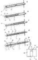
- the single figure shows the execution of a preferred embodiment variant of the method according to the invention in five steps.
- a bore 5 is made in a floor or an approximately vertical wall area by means of a drilling tool 20.
- a hardenable mass 12 can be introduced into the bore 5 via a drill tip 21 in order to form a primary anchor foot 16, as is clearly illustrated in steps b) and c).
- the rod-shaped tension member 14 for forming the injection anchor 10 and the rod-shaped injection member 22 can be arranged within the drilling tool 20, so that they can already be introduced into the bore 5 with the drilling tool 20. After reaching the desired depth, the outer drilling tool 20 can be withdrawn again from the bore 5, the free space in the bore 5 being filled at least in regions with the hardenable mass 12, as is clearly illustrated in steps c) and d). In this method, the drilling tool 20 also serves as an injection member 22 for injecting the hardenable mass 12 for forming the primary anchor foot 16 and, if appropriate, for forming a further region of the injection anchor 10.
- a tubular post-compression member 30 with a hollow base body 32 is introduced into the bore 5 with the tension member 14, as long as the hardenable mass 12 is still in a soft, flowable state.
- a post-compression section 34 is arranged at least in sections, which covers press-out openings 36 in the tubular base body 32.
- an automatic post-injection device 40 is connected to the free end of the post-injection member 30 protruding from the floor via a connection 38 and a line 49.
- the post-injection machine 40 has a box-like frame 42 with a controller 44, at least one container 48 for receiving a post-injection medium 26 and a pressure device 50 for generating a desired injection pressure.
- the controller 44 is provided with a timer 46 with which a point in time can be entered at which post-injection medium 26 can be automatically introduced from the container 48 by means of the pressure device 50 under pressure into the post-injection member 30 by means of the post-injection machine 40.
- the secondary injection medium 26 which can in particular be identical to the hardenable mass 12, it can be introduced into the bore 5 at a predeterminable point in time at which the primary anchor foot 16 is partially but not yet fully hardened.
- the one or more secondary injection sections 34 on the secondary injection member 30 can be torn open, so that the outlet openings 36 in the base body 32 of the secondary injection member 30 are released.
- the flowable secondary injection medium 26 can penetrate into the area of the primary anchor foot 16, break it open and expand it into an enlarged, approximately pear-shaped secondary anchor foot 18. After complete curing, a diameter-widened secondary anchor foot 18 is thus achieved, in which the tension member 14 is firmly integrated, so that relatively high forces can be dissipated into the ground via the tension member 14 and the expanded secondary anchor foot 18.
- the tension member 14 can be surrounded by a cylindrical tube element 15.
- the automatic repressing device 40 can be removed again by disconnecting the line 49 at the connection 38 and can be provided for a further repressing process.
Landscapes
- Engineering & Computer Science (AREA)
- Structural Engineering (AREA)
- Life Sciences & Earth Sciences (AREA)
- General Life Sciences & Earth Sciences (AREA)
- Mining & Mineral Resources (AREA)
- Paleontology (AREA)
- Civil Engineering (AREA)
- General Engineering & Computer Science (AREA)
- Piles And Underground Anchors (AREA)
Abstract
Description
- Die Erfindung betrifft ein Verfahren zum Herstellen eines Injektionsankers im Boden, wobei eine Bohrung in dem Boden erstellt wird, mittels eines Injektionsgliedes zumindest in einem Teilbereich der Bohrung eine aushärtende Masse zum Bilden eines Ankerfußes injiziert wird und nach einem teilweisen, noch nicht vollständigen Aushärten der Masse in einem Bereich des Ankerfußes über ein Nachverpressglied unter Druck ein Nachverpressmedium eingebracht wird, durch welches der noch nicht vollständig ausgehärtete Ankerfuß aufgebrochen wird, gemäß dem Oberbegriff des Anspruchs 1.
- Die Erfindung betrifft weiterhin einen Nachverpressautomaten für ein solches Verfahren nach Anspruch 9.
- Aus der
DE 2 050 292 A ist ein Verfahren zum Herstellen eines Injektionsankers, auch Verpressanker genannt, mit erweitertem Ankerfuß bekannt. Dabei wird zunächst im Boden eine Bohrung erstellt, in welche ein Zugglied für den Anker eingebracht wird. In einem Verankerungsbereich des Zuggliedes wird durch Injizieren von erhärtendem Baustoff ein Ankerfuß im Boden gebildet. Über ein Injektionsrohr, welches zusammen mit dem Zugglied in die Bohrung eingebracht wird, wird vor einem vollständigen Erhärten des Baustoffes für den Ankerfuß durch das Injektionsrohr unter hohem Druck weiterer erhärtender Baustoff in den Verankerungsbereich verpresst. Hierdurch wird der in dem ersten Schritt erstellte und teilweise ausgehärtete primäre Ankerfuß aufgebrochen und kann so insbesondere in radialer Richtung zu einem sekundären Ankerfuß erweitert werden, durch welchen eine stärkere Verankerung des Zuggliedes erreicht werden kann. - Dieses Verfahren wird seit langem mit großem Erfolg angewendet. Für das Aufbrechen des primären Ankerfußes ist es erforderlich, dass die zum Bilden des Ankerfußes vorgesehene Masse teilweise, jedoch noch nicht vollständig ausgehärtet ist. Eine gewisse Festigkeit ist notwendig, damit der Ankerfuß aufreißen kann und sich entsprechende Risse und Teilstücke bilden können. Andererseits darf der Ankerfuß noch nicht vollständig oder weitgehend ausgehärtet sein, da ansonsten der für das Aufbrechen des Ankerfußes notwendige Druck aus wirtschaftlicher Sicht zu hoch wäre oder gar nicht mehr aufgebracht werden könnte. Üblicherweise beträgt die Zeitdauer für das notwendige erste Aushärten des Ankerfußes mehrere Stunden, typischerweise etwa einen Tag.
- Üblicherweise wird an Baustellen der Ankerfuß an einem ersten Tag hergestellt, während dann das Nachverpressen mit dem Aufreißen des Ankerfußes am Folgetag durchgeführt wird. Dies hat zur Folge, dass während einer Arbeitswoche auf einer Baustelle in der Regel Verpressanker von Montag bis Donnerstag hergestellt werden, wobei das Nachverpressen am Folgetag durchgeführt wird. Da jedoch am Samstag und am Sonntag üblicherweise auf Baustellen nicht gearbeitet wird, werden an einem Freitag keine Injektionsanker mit primären Ankerfüßen mehr erstellt, da ein Durchführen des Nachverpressens erst am folgenden Montag nicht oder kaum mehr möglich wäre, da aufgrund der vorangeschritten Aushärtung des Ankerfußes dieser nicht mehr durch ein Nachverpressmedium zuverlässig aufgebrochen werden könnte.
- Faktisch stehen somit bei üblichen Bauvorhaben für das Herstellen eines Injektionsankers mit einem nachzuverpressenden Ankerfuß nur vier Arbeitstage, nämlich Montag bis Donnerstag, zur Verfügung.
- Der Erfindung liegt die Aufgabe zugrunde, ein Verfahren zum Herstellen eines Injektionsankers im Boden und eine Vorrichtung hierfür anzugeben, bei welchen eine erhöhte zeitliche Flexibilität bei der Herstellung von Injektionsanker gegeben ist.
- Nach der Erfindung wird die Aufgabe zum einen durch ein Verfahren mit den Merkmalen des Anspruchs 1 und zum anderen mit einem Nachverpressautomat mit den Merkmalen des Anspruchs 9 gelöst. Bevorzugte Ausführungsformen der Erfindung sind in den jeweiligen abhängigen Ansprüchen angegeben.
- Das erfindungsgemäße Verfahren ist dadurch gekennzeichnet, dass an dem Nachverpressglied ein Nachverpressautomat angeschlossen wird, durch welchen zu einem frei vorgebbaren Zeitpunkt automatisch das Nachverpressmedium zum Aufbrechen des noch nicht vollständig ausgehärteten Ankerfußes in das Nachverpressglied eingeleitet wird.
- Eine Grundidee der Erfindung liegt darin, dass ein Nachverpressen eines Ankerfußes ohne Personal durch einen speziellen Nachverpressautomaten durchgeführt werden kann. Dabei wird der Nachverpressautomat mit dem Nachverpressglied leitungsverbunden, wobei das Nachverpressmedium zum Aufbrechen des noch nicht ausgehärteten primären Ankerfußes in das Nachverpressglied automatisch eingeleitet werden kann. Dabei kann in den Nachverpressautomat ein beliebiger Zeitpunkt eingegeben werden, zu welchem dann das Nachverpressmedium in das Nachverpressglied eingeleitet wird. Der Zeitpunkt zum Nachverpressen kann auch von einer entfernten Zentrale über eine vorzugsweise drahtlose Datenverbindung oder abhängig von Sensoren geschaltet werden, welche etwa einen Zustand des primären Ankerfußes, wie Festigkeit oder Restfeuchte etc., der Umgebung oder anderer relevanter Parameter ermitteln.
- Somit kann ein Nachverpressen unabhängig von der Anwesenheit von Personal und somit auch an Wochenenden, Feiertagen, Morgen- oder Nachtstunden durchgeführt werden. Insbesondere kann durch den Einsatz eines Nachverpressautomaten nunmehr auch grundsätzlich auf Baustellen der Freitag zum Herstellen von Injektionsankern vorgesehen werden. Dies führt zu einer verbesserten Auslastung des Maschinenparks, zur Erhöhung der Wochenleistung bei zu erstellenden Injektionsankern und zur Verkürzung der Bauzeit. Im Ergebnis führt dies zu erheblichen Kostenvorteilen.
- Abhängig von der Art der Herstellung des Injektionsankers wird ein Zugglied für den Anker beim oder nach dem Erstellen der Bohrung in diese eingebracht, wobei jeweils sicherzustellen ist, dass das Zugglied mit dem gebildeten Ankerfuß zuverlässig verbunden ist.
- Eine bevorzugte Ausführungsform der Erfindung besteht darin, dass das Nachverpressmedium eine Flüssigkeit, insbesondere Wasser, oder ein Gas, insbesondere Druckluft, ist, durch welches der Ankerfuß aufgebrochen wird und dass zeitlich beabstandet in den aufgebrochenen Ankerfuß ein aushärtbares Medium eingeleitet wird. Bei diesem zweistufigen Nachverpressen erfolgt zu dem vorgegebenen Zeitpunkt zunächst ein Aufbrechen des primären Ankerfußes durch ein nicht-aushärtendes Medium, insbesondere Wasser oder Druckluft. Dieser erste Schritt kann durch den Nachverpressautomat durchgeführt werden, wobei das Speichern von Wasser oder Druckluft, die insbesondere aus der Umgebungsluft gebildet wird, problemlos möglich ist. Der zweite Schritt des Nachverpressens durch Einleiten eines aushärtenden Mediums in den aufgebrochenen primären Ankerfuß kann entweder ebenfalls durch den Nachverpressautomat, der dann einen zusätzlichen Speicher und gegebenenfalls eine zusätzliche Druckeinrichtung zum Erzeugen des Drucks für das aushärtbare Medium aufweist, durchgeführt werden. Alternativ kann der zweite Schritt des Nachverpressens nicht automatisch durch Personal zu einem späteren Zeitpunkt durchgeführt werden. Nach dem Aufbrechen des primären Ankerfußes können die aufgebrochenen Ankerfußteile bis zum Einleiten des aushärtenden Mediums selbst aushärten.
- Besonders bevorzugt ist es nach einer Weiterbildung der Erfindung, dass als Nachverpressmedium eine aushärtbares Medium verwendet wird, insbesondere die aushärtende Masse zum Bilden des Ankerfußes. Hierbei wird also das Nachverpressen in einem einzigen Schritt durchgeführt, wobei das Nachverpressmedium insbesondere eine Zementsuspension oder eine andere aushärtbare Suspension sein kann. Bei Verwendung der gleichen aushärtbaren Masse wie zum Bilden des primären Ankerfußes kann so ein besonders stabiler finaler sekundärer Ankerfuß erzeugt werden.
- Zum Herstellen des Ankergliedes gibt es grundsätzlich verschiedene Verfahrensabläufe, welche aus dem Stand der Technik bekannt sind und insbesondere in dem eingangs genannten Dokument
DE 2 050 292 A beschrieben und dargestellt sind. Die Erfindung umfasst alle diese grundsätzlichen Verfahrensvarianten zur Herstellung eines Injektionsankers, jedoch mit dem Schritt des automatischen Nachverpressens. Besonders bevorzugt ist es nach einer Ausführungsform der Erfindung, dass das Injektionsglied zum Injizieren der aushärtbaren Masse und ein separates Nachverpressglied zum Injizieren des Nachverpressmediums in der Bohrung verbleiben. Vorteilhafterweise können das Injektionsglied und das Nachverpressglied zusammen mit dem Zugglied in die Bohrung eingebracht werden. Alternativ könnte das Injektionsglied auch als Nachverpressglied für das Nachverpressmedium und/ oder ein anderes aushärtbares Medium zum Bilden des sekundären Ankerfußes eingesetzt werden. Grundsätzlich kann das Injektionsglied ein separates Element sein, welches mit oder nach dem Entfernen des Bohrwerkzeuges in die Bohrung eingebracht wird. Besonders vorteilhaft ist es nach einer Ausführungsvariante der Erfindung, dass das Injektionsglied als ein Bohrwerkzeug ausgebildet ist, mit welchem die Bohrung im Boden erstellt wird. Das Injektionsglied kann gleichzeitig oder alternativ ein Teil des Zuggliedes sein, so dass ein insgesamt einfacher Arbeitsablauf erreicht wird. - Eine besonders zweckmäßige Verfahrensvariante besteht weiterhin darin, dass das Nachverpressglied mindestens eine Austrittsöffnung aufweist, durch welche das Nachverpressmedium in die Bohrung eingeleitet wird. Das schlauch- oder rohrartige Nachverpressglied kann im Bereich des zu bildenden Ankerfußes einen Abschnitt mit mehreren Öffnungen oder mit verminderter Materialstärke aufweisen, welcher beim Einleiten des Nachverpressmediums mit einem vorgegebenen Druck definiert aufreißt. Hierdurch kann das Nachverpressmedium in den umgebenden Bereich austreten und den primären Ankerfuß aufbrechen beziehungsweise ein aushärtbares Medium zum Bilden des sekundären Ankerfußes einleiten.
- Abhängig vom Verfahren wird dabei ein geeigneter Druck eingestellt. Nach einer Ausführungsform der Erfindung ist es in bevorzugter Weise vorgesehen, dass ein Druck zum Einleiten des Nachverpressmediums von mindestens 10 bar, vorzugsweise zwischen 15 bar und 40 bar eingestellt wird. In besonderen Fällen können auch kleinere oder größere Drücke vorgesehen sein.
- Weiterhin ist es nach einer Fortbildung der Erfindung besonders vorteilhaft, dass der Nachverpressautomat mit einer Steuerung versehen ist, in der eine Zeit zum Ausführen des automatischen Nachverpressens eingegeben wird. Die Steuerung kann dabei insbesondere eine Zeitschaltuhr aufweisen, mit welcher insbesondere eine Zeitspanne oder ein definierter Zeitpunkt zum Durchführen des automatischen Nachverpressens eingegeben werden kann. Bei Erreichen des eingegebenen Zeitpunktes kann dann über die mechanische oder vorzugsweise elektronische Steuerung der Nachverpressautomat zum Einleiten des Nachverpressmediums in der gewünschten Weise in Betrieb gesetzt werden.
- Die Steuerung kann dabei zusätzlich eine Eingabeeinrichtung zum Eingeben des notwendigen Drucks, der einzuleitenden Füllmenge und/oder eines Grenzdrucks versehen sein, bei welchem der Nachverpressvorgang gestoppt werden kann.
- Die erfindungsgemäße Vorrichtung ist als ein Nachverpressautomat ausgebildet, welcher dadurch gekennzeichnet ist, dass eine Druckeinrichtung vorgesehen ist, welche mit dem Nachverpressglied leitungsverbindbar ist und welche zum Einleiten des Nachverpressmediums unter Druck in das Nachverpressglied ausgebildet ist, und dass eine Steuerung vorgesehen ist, in welcher ein Zeitpunkt zum automatischen Einleiten des Nachverpressmediums in das Nachverpressglied ausgebildet ist.
- Mit dem erfindungsgemäßen Nachverpressautomat kann insbesondere das zuvor beschriebene Verfahren durchgeführt und die damit verbundenen Vorteile erreicht werden.
- Eine bevorzugte Ausführungsform besteht nach der Erfindung darin, dass mindestens ein Behälter zum Aufnehmen des Nachverpressmediums vorgesehen ist. Der Behälter kann dabei auch ein Druckbehälter sein, in dem das Medium, insbesondere Druckluft, unter Druck gespeichert ist. Grundsätzlich können auch mehrere, insbesondere zwei, Behälter vorgesehen sein, so dass etwa in einem Behälter Druckluft und in einem anderen Behälter das aushärtbare Medium gelagert ist.
- Die Druckeinrichtung kann jede geeignete Einrichtung zum Erzeugen eines Druckes sein, etwa ein Druckspeicherbehälter mit komprimiertem Gas oder einer Druckfedereinheit. Es ist nach einer Ausführungsform der Erfindung besonders bevorzugt, dass die Druckeinrichtung eine Pumpe und/oder einen Kompressor aufweist. Hierdurch kann der notwendige Druck zum Einleiten des Nachverpressmediums aufgebracht werden. Vorzugsweise sind die Komponenten des Nachverpressautomaten elektrisch betrieben. Der Nachverpressautomat kann zur Energieversorgung mit Batterien versehen sein oder eine Verbindung zu einer externen Stromquelle aufweisen. Grundsätzlich sind auch andere Energiequellen zum Betreiben des Nachverpressautomaten möglich.
- Grundsätzlich kann für jedes einzelne Nachverpressglied ein einzelner Nachverpressautomat vorgesehen sein. Hierdurch kann der Nachverpressautomat insgesamt sehr kompakt ausgebildet werden. Eine alternative und bevorzugte Ausführungsform der Erfindung kann darin gesehen werden, dass der Nachverpressautomat über mehrere Leitungen an mehrere Nachverpressglieder angeschlossen ist. Bei dieser Anordnung kann insbesondere ein zentraler Nachverpressautomat mehrere Nachverpressglieder mit dem Nachverpressmedium versorgen. Die Steuerung kann dabei so ausgelegt sein, dass dies gleichzeitig für alle oder mehrere Nachverpressglieder erfolgt oder dass die Nachverpressvorgänge an den einzelnen Nachverpressgliedern sukzessive durchgeführt werden.
- Nachfolgend wird die Erfindung anhand eines bevorzugten Ausführungsbeispieles weiter beschrieben, welches schematisch in der beigefügten Zeichnung dargestellt ist.
- In der einzigen Figur ist in fünf Schritten die Ausführung einer bevorzugten Ausführungsvariante des erfindungsgemäßen Verfahrens dargestellt.
- Dabei wird in einem Schritt a) mittels eines Bohrwerkzeuges 20 eine Bohrung 5 in einen Boden oder einen etwa vertikalen Wandbereich eingebracht. Über eine Bohrerspitze 21 kann eine aushärtbare Masse 12 in die Bohrung 5 eingebracht werden, um einen primären Ankerfuß 16 zu bilden, wie anschaulich in den Schritten b) und c) dargestellt ist.
- Innerhalb des Bohrwerkzeuges 20 kann das stangenförmige Zugglied 14 zum Bilden des Injektionsankers 10 sowie das stangenförmige Injektionsglied 22 angeordnet sein, so dass diese bereits mit dem Bohrwerkzeug 20 in die Bohrung 5 eingebracht werden können. Nach Erreichen der gewünschten Tiefe kann das äußere Bohrwerkzeug 20 wieder aus der Bohrung 5 rückgezogen werden, wobei der Freiraum in der Bohrung 5 mit der aushärtbaren Masse 12 zumindest bereichsweise verfüllt wird, wie in den Schritten c) und d) anschaulich dargestellt ist. Bei diesem Verfahren dient das Bohrwerkzeug 20 gleichzeitig als ein Injektionsglied 22 zum Injizieren der aushärtbaren Masse 12 zum Bilden des primären Ankerfußes 16 sowie gegebenenfalls zum Bilden eines weiteren Bereiches des Injektionsankers 10.
- Gemäß der Erfindung wird mit dem Zugglied 14 ein schlauchförmiges Nachverpressglied 30 mit einem hohlen Grundkörper 32 in die Bohrung 5 eingebracht, solange die aushärtbare Masse 12 sich noch in einem weichen, fließfähigen Zustand befindet. Am bodenseitigen Endbereich des Grundkörpers 32 des Nachverpressgliedes 30 ist zumindest abschnittsweise ein Nachverpressabschnitt 34 angeordnet, welcher Auspressöffnungen 36 in dem schlauchförmigen Grundkörper 32 abdeckt.
- Wie anschaulich in Schritt e) dargestellt ist, wird am freien, aus dem Boden herausragenden Ende des Nachverpressgliedes 30 über einen Anschluss 38 und eine Leitung 49 ein erfindungsgemäßer Nachverpressautomat 40 angeschlossen.
- Der Nachverpressautomat 40 weist ein kastenartiges Gestell 42 mit einer Steuerung 44, mindestens einem Behälter 48 zum Aufnehmen eines Nachverpressmediums 26 und einer Druckeinrichtung 50 zum Erzeugen eines gewünschten Injizierdruckes auf. Die Steuerung 44 ist mit einer Zeitschaltuhr 46 versehen, mit der ein Zeitpunkt eingebbar ist, zu welchem mittels des Nachverpressautomaten 40 automatisch Nachverpressmedium 26 aus dem Behälter 48 mittels der Druckeinrichtung 50 unter Druck in das Nachverpressglied 30 einleitbar ist.
- Durch das Einleiten des Nachverpressmediums 26, welches insbesondere identisch mit der aushärtbaren Masse 12 sein kann, kann zu einem vorgebbaren Zeitpunkt, bei dem der primäre Ankerfuß 16 teilweise, aber noch nicht vollständig ausgehärtet ist, in die Bohrung 5 eingeleitet werden. Dabei kann bei einem Druck von beispielsweise 15 bar das eine oder die mehreren Nachverpressabschnitte 34 am Nachverpressglied 30 aufgerissen werden, so dass die Austrittsöffnungen 36 im Grundkörper 32 des Nachverpressgliedes 30 freigegeben werden. Das strömungsfähige Nachverpressmedium 26 kann dabei in den Bereich des primären Ankerfußes 16 eindringen, diesen aufbrechen und zu einem vergrößerten, etwa birnenförmigen sekundären Ankerfuß 18 aufweiten. Nach vollständiger Aushärtung wird so ein durchmessererweiterter sekundärer Ankerfuß 18 erreicht, in dem das Zugglied 14 fest eingebunden ist, so dass über das Zugglied 14 und den erweiterten sekundären Ankerfuß 18 relativ hohe Kräfte in den Boden abgetragen werden können.
- In einem oberen Bereich des Injektionsankers 10 kann das Zugglied 14 von einem zylindrischen Rohrelement 15 umgeben sein.
- Nach Abschluss des Nachverpressens, welches insbesondere ohne Personal an Wochenenden ausgeführt werden kann, kann der Nachverpressautomat 40 durch Trennen der Leitung 49 am Anschluss 38 wieder entfernt und für einen weiteren Nachpressvorgang vorgesehen werden.
Claims (12)
- Verfahren zum Herstellen eines Injektionsankers (10) im Boden, wobei- eine Bohrung (5) in dem Boden erstellt wird,- mittels eines Injektionsgliedes (22) zumindest in einem Teilbereich der Bohrung (5) eine aushärtende Masse (12) zum Bilden eines Ankerfußes (16) injiziert wird und- nach einem teilweisen, noch nicht vollständigen Aushärten der Masse (12) in einen Bereich des Ankerfußes (16) über ein Nachverpressglied (30) unter Druck ein Nachverpressmedium (26) eingebracht wird, durch welches der noch nicht vollständig ausgehärtete Ankerfuß (16) aufgebrochen wird,dadurch gekennzeichnet,
dass an dem Nachverpressglied (30) ein Nachverpressautomat (40) angeschlossen wird, durch welchen zu einem frei vorgebbaren Zeitpunkt automatisch das Nachverpressmedium (26) zum Aufbrechen des noch nicht ausgehärteten Ankerfußes (16) in das Nachverpressglied (30) eingeleitet wird. - Verfahren nach Anspruch 1,
dadurch gekennzeichnet,
dass das Nachverpressmedium (26) eine Flüssigkeit, insbesondere Wasser, oder ein Gas, insbesondere Druckluft, ist, durch welches der Ankerfuß (16) aufgebrochen wird, und
dass zeitlich beabstandet in den aufgebrochenen Ankerfuß (16) ein aushärtbares Medium eingeleitet wird. - Verfahren nach Anspruch 1,
dadurch gekennzeichnet,
dass als Nachverpressmedium (26) ein aushärtbares Medium verwendet wird, insbesondere die aushärtende Masse (12) zum Bilden des Ankerfußes (16). - Verfahren nach einem der Ansprüche 1 bis 3,
dadurch gekennzeichnet,
dass das Injektionsglied (22) zum Injizieren der aushärtbaren Masse (12) und des Nachverpressglieds (30) zum Injizieren des Nachverpressmedums (26) in der Bohrung (5) verbleiben. - Verfahren nach einem der Ansprüche 1 bis 4,
dadurch gekennzeichnet,
dass das Injektionsglied (22) als ein Bohrwerkzeug (20) ausgebildet ist, mit welchem die Bohrung (5) im Boden erstellt wird. - Verfahren nach einem der Ansprüche 1 bis 5,
dadurch gekennzeichnet,
dass das Nachverpressglied (30) mindestens eine Austrittsöffnung aufweist, durch welche das Nachverpressmedium (26) in die Bohrung (5) eingeleitet wird. - Verfahren nach einem der Ansprüche 1 bis 6,
dadurch gekennzeichnet,
dass ein Druck zum Einleiten des Nachverpressmediums (26) von mindestens 10 bar, vorzugsweise zwischen 15 bar und 40 bar, eingestellt wird. - Verfahren nach einem der Ansprüche 1 bis 7,
dadurch gekennzeichnet,
dass der Nachverpressautomat (40) mit einer Steuerung (44) versehen ist, in welcher eine Zeit zum Ausführen des automatischen Nachverpressens eingegeben wird. - Nachverpressautomat für ein Verfahren nach einem der Ansprüche 1 bis 8,
dadurch gekennzeichnet,
dass eine Druckeinrichtung (50) vorgesehen ist, welche mit dem Nachverpressglied (30) leitungsverbindbar ist und welche zum Einleiten des Nachverpressmediums (26) unter Druck in das Nachverpressglied (30) ausgebildet ist, und dass eine Steuerung (44) vorgesehen ist, in welcher ein Zeitpunkt zum automatischen Einleiten des Nachverpressmediums (26) in das Nachverpressglied (30) ausgebildet ist. - Nachverpressautomat nach Anspruch 9,
dadurch gekennzeichnet,
dass mindestens ein Behälter (48) zum Aufnehmen des Nachverpressmediums (26) vorgesehen ist. - Nachverpressautomat nach Anspruch 9 oder 10,
dadurch gekennzeichnet,
dass die Druckeinrichtung (50) eine Pumpe und/oder einen Kompressor aufweist. - Nachverpressautomat nach Anspruch 9 bis 11,
dadurch gekennzeichnet,
dass dieser über mehrere Leitungen (49) an mehrere Nachverpressglieder (30) angeschlossen ist.
Priority Applications (3)
| Application Number | Priority Date | Filing Date | Title |
|---|---|---|---|
| EP18196794.4A EP3628781B1 (de) | 2018-09-26 | 2018-09-26 | Verfahren zum herstellen eines injektionsankers im boden und nachverpressautomat hierfür |
| PCT/EP2019/071721 WO2020064208A1 (de) | 2018-09-26 | 2019-08-13 | Verfahren zum herstellen eines injektionsankers im boden und nachverpressautomat hierfür |
| US17/275,807 US11993910B2 (en) | 2018-09-26 | 2019-08-13 | Method for producing an injection anchor in the ground and automatic post-grouting machine for the same |
Applications Claiming Priority (1)
| Application Number | Priority Date | Filing Date | Title |
|---|---|---|---|
| EP18196794.4A EP3628781B1 (de) | 2018-09-26 | 2018-09-26 | Verfahren zum herstellen eines injektionsankers im boden und nachverpressautomat hierfür |
Publications (2)
| Publication Number | Publication Date |
|---|---|
| EP3628781A1 true EP3628781A1 (de) | 2020-04-01 |
| EP3628781B1 EP3628781B1 (de) | 2023-06-07 |
Family
ID=63787722
Family Applications (1)
| Application Number | Title | Priority Date | Filing Date |
|---|---|---|---|
| EP18196794.4A Active EP3628781B1 (de) | 2018-09-26 | 2018-09-26 | Verfahren zum herstellen eines injektionsankers im boden und nachverpressautomat hierfür |
Country Status (3)
| Country | Link |
|---|---|
| US (1) | US11993910B2 (de) |
| EP (1) | EP3628781B1 (de) |
| WO (1) | WO2020064208A1 (de) |
Cited By (1)
| Publication number | Priority date | Publication date | Assignee | Title |
|---|---|---|---|---|
| CN116575449A (zh) * | 2023-07-03 | 2023-08-11 | 中国华西企业有限公司 | 一种格构梁试验锚杆装置的施工方法 |
Citations (3)
| Publication number | Priority date | Publication date | Assignee | Title |
|---|---|---|---|---|
| DE2050292A1 (de) | 1970-10-13 | 1972-06-29 | Bauer, Dipl Ing , Dr Ing , Karlheinz, 8898 Schrobenhausen | Verfahren zum Herstellen von Erd ankern mit erweitertem Ankerfuß |
| EP0218987A2 (de) * | 1985-10-03 | 1987-04-22 | Dyckerhoff & Widmann Aktiengesellschaft | Verfahren zum Setzen eines Einbauteils durch eine Spundwand in eine Bodenformation mit drückendem Wasser sowie Vorrichtung zum Durchführen des Verfahrens |
| DE102009029892A1 (de) * | 2008-11-01 | 2011-09-15 | Reinhard Klöckner | Vorrichtung zur Einleitung von Zugkräften in den Untergrund beispielsweise für Abspannseile von Fangnetzen für die Steinschlag- und Lawinensicherung sowie Verfahren zur Herstellung und Dimensionierung dieser Vorrichtung |
Family Cites Families (10)
| Publication number | Priority date | Publication date | Assignee | Title |
|---|---|---|---|---|
| US2949705A (en) * | 1953-06-05 | 1960-08-23 | Carl F Spickelmier | Reinforced concrete slab construction |
| US3222873A (en) * | 1961-07-31 | 1965-12-14 | Chester I Williams | Groutable rock anchor |
| US3336758A (en) * | 1965-01-11 | 1967-08-22 | Chester I Williams | Rock bolt assembly and procedure for two-stage grouting operations |
| DE2101236A1 (de) * | 1971-01-12 | 1972-08-17 | Bauer, Karlheinz, Dipl.-Ing. Dr.-Ing., 8898 Schrobenhausen | Korrosionsgeschützter Zuganker zur Verankerung von Bauteilen im Erdreich sowie Verfahren zur Herstellung von Zugverankerungen mit korrosionsgeschützten Zugankern |
| JPS61196070A (ja) * | 1985-02-27 | 1986-08-30 | 大成建設株式会社 | 構造物の止水方法 |
| KR100775645B1 (ko) * | 2004-08-26 | 2007-11-13 | 손정찬 | 그라우트 주입을 위한 자동제어장치, 주입시스템 및 그제어방법 |
| US20070286687A1 (en) * | 2006-06-12 | 2007-12-13 | Cesare Melegari | Method and equipment for constructing micropiles in soil |
| JP2014051798A (ja) * | 2012-09-06 | 2014-03-20 | Splice Sleeve Japan Ltd | 鉄筋の継手工法 |
| US10253628B2 (en) * | 2016-09-02 | 2019-04-09 | J-Lok Co. | Pumpable resin system |
| CN107447756A (zh) * | 2017-09-25 | 2017-12-08 | 西南石油大学 | 一种补偿锚索预应力损失的施工装置及补偿施工方法 |
-
2018
- 2018-09-26 EP EP18196794.4A patent/EP3628781B1/de active Active
-
2019
- 2019-08-13 US US17/275,807 patent/US11993910B2/en active Active
- 2019-08-13 WO PCT/EP2019/071721 patent/WO2020064208A1/de not_active Ceased
Patent Citations (3)
| Publication number | Priority date | Publication date | Assignee | Title |
|---|---|---|---|---|
| DE2050292A1 (de) | 1970-10-13 | 1972-06-29 | Bauer, Dipl Ing , Dr Ing , Karlheinz, 8898 Schrobenhausen | Verfahren zum Herstellen von Erd ankern mit erweitertem Ankerfuß |
| EP0218987A2 (de) * | 1985-10-03 | 1987-04-22 | Dyckerhoff & Widmann Aktiengesellschaft | Verfahren zum Setzen eines Einbauteils durch eine Spundwand in eine Bodenformation mit drückendem Wasser sowie Vorrichtung zum Durchführen des Verfahrens |
| DE102009029892A1 (de) * | 2008-11-01 | 2011-09-15 | Reinhard Klöckner | Vorrichtung zur Einleitung von Zugkräften in den Untergrund beispielsweise für Abspannseile von Fangnetzen für die Steinschlag- und Lawinensicherung sowie Verfahren zur Herstellung und Dimensionierung dieser Vorrichtung |
Cited By (1)
| Publication number | Priority date | Publication date | Assignee | Title |
|---|---|---|---|---|
| CN116575449A (zh) * | 2023-07-03 | 2023-08-11 | 中国华西企业有限公司 | 一种格构梁试验锚杆装置的施工方法 |
Also Published As
| Publication number | Publication date |
|---|---|
| WO2020064208A1 (de) | 2020-04-02 |
| US20220049448A1 (en) | 2022-02-17 |
| EP3628781B1 (de) | 2023-06-07 |
| US11993910B2 (en) | 2024-05-28 |
Similar Documents
| Publication | Publication Date | Title |
|---|---|---|
| EP0394179B1 (de) | Kombinierter starrer Profil- und Dehnanker mit Spreizelement | |
| DE69837524T2 (de) | Verfahren zur Herstellung einer Verankerung, Verankerungsteil und Spannelement zu diesem Zweck | |
| EP2257690B1 (de) | Korrosionsgeschützter selbstbohranker sowie ankerteileinheit und verfahren zu dessen herstellung | |
| DE1226516B (de) | Verfahren zum zweistufigen Einbetonieren von Gebirgsanker und ein Anker hierfuer | |
| DE102009001749B4 (de) | Anschlussvorrichtung und Verfahren zur Erstellung eines Anschlusses | |
| DE3400350C2 (de) | ||
| DE3535320A1 (de) | Verfahren und vorrichtung zum setzen eines stab-, draht- oder rohrfoermigen einbauteils in eine bodenformation mit drueckendem wasser | |
| EP3628781B1 (de) | Verfahren zum herstellen eines injektionsankers im boden und nachverpressautomat hierfür | |
| DE3416679C2 (de) | ||
| AT511240B1 (de) | Verfahren zum erstellen eines bauwerkes und mauerwerk-verankerungssystem | |
| DE3732894C2 (de) | ||
| DE3838880C1 (en) | Method of producing a grouted anchor, and grouted anchor for carrying out the method | |
| EP2003251A1 (de) | Trägerverbau | |
| DE2806840B2 (de) | Verfahren und Vorrichtung zum Entfernen eines Verpreßankers | |
| DE10258300B4 (de) | Verfahren und Vorrichtung zur Stabilisierung von abgeworfenen Bergwerksschächten | |
| DE2449289B2 (de) | Vorspannbarer verpress-anker | |
| DE3033715A1 (de) | Verfahren zur untergrundverbesserung und dazu dienender gruendungspfahl, -anker o.dgl. | |
| DE2617758A1 (de) | Verfahren zum einbringen von kunststoff-fuellungen in waende, mauern, fassadenwaende u.dgl. und vorrichtung zur durchfuehrung dieses verfahrens | |
| DE102020125370A1 (de) | Vorrichtung zum Befüllen von Bohrlöchern mit kleinem Durchmesser mit Injektionsmaterial zwecks Einbringung und Befestigung von Ankern | |
| DE102004059632A1 (de) | Fundamenteinrichutng für stabförmige Bauteile mit mehrfach verwendbarem Werkzeug sowie Vorrichtung zum einbringen einer derartigen Fundamenteinrichtung | |
| DE102021116487B3 (de) | Geotextilummantelte Flüssigbodensäulen | |
| AT394449B (de) | Vorrichtung zur bestimmung von zug- und/oder druckspannungen sowie verfahren zum setzen derselben | |
| DE1634273A1 (de) | Erdanker und Verfahren zu seiner Herstellung | |
| EP4520870A1 (de) | Geotechnischer anker mit quellkörper, ankersystem und herstellung des ankersystems | |
| DE3824955A1 (de) | Verfahren zum herstellen von bodenankern |
Legal Events
| Date | Code | Title | Description |
|---|---|---|---|
| PUAI | Public reference made under article 153(3) epc to a published international application that has entered the european phase |
Free format text: ORIGINAL CODE: 0009012 |
|
| STAA | Information on the status of an ep patent application or granted ep patent |
Free format text: STATUS: THE APPLICATION HAS BEEN PUBLISHED |
|
| AK | Designated contracting states |
Kind code of ref document: A1 Designated state(s): AL AT BE BG CH CY CZ DE DK EE ES FI FR GB GR HR HU IE IS IT LI LT LU LV MC MK MT NL NO PL PT RO RS SE SI SK SM TR |
|
| AX | Request for extension of the european patent |
Extension state: BA ME |
|
| STAA | Information on the status of an ep patent application or granted ep patent |
Free format text: STATUS: REQUEST FOR EXAMINATION WAS MADE |
|
| 17P | Request for examination filed |
Effective date: 20200713 |
|
| RBV | Designated contracting states (corrected) |
Designated state(s): AL AT BE BG CH CY CZ DE DK EE ES FI FR GB GR HR HU IE IS IT LI LT LU LV MC MK MT NL NO PL PT RO RS SE SI SK SM TR |
|
| STAA | Information on the status of an ep patent application or granted ep patent |
Free format text: STATUS: EXAMINATION IS IN PROGRESS |
|
| 17Q | First examination report despatched |
Effective date: 20201112 |
|
| GRAP | Despatch of communication of intention to grant a patent |
Free format text: ORIGINAL CODE: EPIDOSNIGR1 |
|
| STAA | Information on the status of an ep patent application or granted ep patent |
Free format text: STATUS: GRANT OF PATENT IS INTENDED |
|
| INTG | Intention to grant announced |
Effective date: 20220809 |
|
| GRAJ | Information related to disapproval of communication of intention to grant by the applicant or resumption of examination proceedings by the epo deleted |
Free format text: ORIGINAL CODE: EPIDOSDIGR1 |
|
| STAA | Information on the status of an ep patent application or granted ep patent |
Free format text: STATUS: EXAMINATION IS IN PROGRESS |
|
| INTC | Intention to grant announced (deleted) | ||
| GRAP | Despatch of communication of intention to grant a patent |
Free format text: ORIGINAL CODE: EPIDOSNIGR1 |
|
| STAA | Information on the status of an ep patent application or granted ep patent |
Free format text: STATUS: GRANT OF PATENT IS INTENDED |
|
| INTG | Intention to grant announced |
Effective date: 20230103 |
|
| GRAS | Grant fee paid |
Free format text: ORIGINAL CODE: EPIDOSNIGR3 |
|
| GRAA | (expected) grant |
Free format text: ORIGINAL CODE: 0009210 |
|
| STAA | Information on the status of an ep patent application or granted ep patent |
Free format text: STATUS: THE PATENT HAS BEEN GRANTED |
|
| AK | Designated contracting states |
Kind code of ref document: B1 Designated state(s): AL AT BE BG CH CY CZ DE DK EE ES FI FR GB GR HR HU IE IS IT LI LT LU LV MC MK MT NL NO PL PT RO RS SE SI SK SM TR |
|
| REG | Reference to a national code |
Ref country code: GB Ref legal event code: FG4D Free format text: NOT ENGLISH |
|
| REG | Reference to a national code |
Ref country code: CH Ref legal event code: EP Ref country code: AT Ref legal event code: REF Ref document number: 1575361 Country of ref document: AT Kind code of ref document: T Effective date: 20230615 |
|
| REG | Reference to a national code |
Ref country code: DE Ref legal event code: R096 Ref document number: 502018012280 Country of ref document: DE |
|
| REG | Reference to a national code |
Ref country code: LT Ref legal event code: MG9D |
|
| REG | Reference to a national code |
Ref country code: NL Ref legal event code: MP Effective date: 20230607 |
|
| PG25 | Lapsed in a contracting state [announced via postgrant information from national office to epo] |
Ref country code: SE Free format text: LAPSE BECAUSE OF FAILURE TO SUBMIT A TRANSLATION OF THE DESCRIPTION OR TO PAY THE FEE WITHIN THE PRESCRIBED TIME-LIMIT Effective date: 20230607 Ref country code: NO Free format text: LAPSE BECAUSE OF FAILURE TO SUBMIT A TRANSLATION OF THE DESCRIPTION OR TO PAY THE FEE WITHIN THE PRESCRIBED TIME-LIMIT Effective date: 20230907 Ref country code: ES Free format text: LAPSE BECAUSE OF FAILURE TO SUBMIT A TRANSLATION OF THE DESCRIPTION OR TO PAY THE FEE WITHIN THE PRESCRIBED TIME-LIMIT Effective date: 20230607 |
|
| PG25 | Lapsed in a contracting state [announced via postgrant information from national office to epo] |
Ref country code: RS Free format text: LAPSE BECAUSE OF FAILURE TO SUBMIT A TRANSLATION OF THE DESCRIPTION OR TO PAY THE FEE WITHIN THE PRESCRIBED TIME-LIMIT Effective date: 20230607 Ref country code: NL Free format text: LAPSE BECAUSE OF FAILURE TO SUBMIT A TRANSLATION OF THE DESCRIPTION OR TO PAY THE FEE WITHIN THE PRESCRIBED TIME-LIMIT Effective date: 20230607 Ref country code: LV Free format text: LAPSE BECAUSE OF FAILURE TO SUBMIT A TRANSLATION OF THE DESCRIPTION OR TO PAY THE FEE WITHIN THE PRESCRIBED TIME-LIMIT Effective date: 20230607 Ref country code: LT Free format text: LAPSE BECAUSE OF FAILURE TO SUBMIT A TRANSLATION OF THE DESCRIPTION OR TO PAY THE FEE WITHIN THE PRESCRIBED TIME-LIMIT Effective date: 20230607 Ref country code: HR Free format text: LAPSE BECAUSE OF FAILURE TO SUBMIT A TRANSLATION OF THE DESCRIPTION OR TO PAY THE FEE WITHIN THE PRESCRIBED TIME-LIMIT Effective date: 20230607 Ref country code: GR Free format text: LAPSE BECAUSE OF FAILURE TO SUBMIT A TRANSLATION OF THE DESCRIPTION OR TO PAY THE FEE WITHIN THE PRESCRIBED TIME-LIMIT Effective date: 20230908 |
|
| PG25 | Lapsed in a contracting state [announced via postgrant information from national office to epo] |
Ref country code: FI Free format text: LAPSE BECAUSE OF FAILURE TO SUBMIT A TRANSLATION OF THE DESCRIPTION OR TO PAY THE FEE WITHIN THE PRESCRIBED TIME-LIMIT Effective date: 20230607 |
|
| PG25 | Lapsed in a contracting state [announced via postgrant information from national office to epo] |
Ref country code: SK Free format text: LAPSE BECAUSE OF FAILURE TO SUBMIT A TRANSLATION OF THE DESCRIPTION OR TO PAY THE FEE WITHIN THE PRESCRIBED TIME-LIMIT Effective date: 20230607 |
|
| PG25 | Lapsed in a contracting state [announced via postgrant information from national office to epo] |
Ref country code: IS Free format text: LAPSE BECAUSE OF FAILURE TO SUBMIT A TRANSLATION OF THE DESCRIPTION OR TO PAY THE FEE WITHIN THE PRESCRIBED TIME-LIMIT Effective date: 20231007 |
|
| PG25 | Lapsed in a contracting state [announced via postgrant information from national office to epo] |
Ref country code: SM Free format text: LAPSE BECAUSE OF FAILURE TO SUBMIT A TRANSLATION OF THE DESCRIPTION OR TO PAY THE FEE WITHIN THE PRESCRIBED TIME-LIMIT Effective date: 20230607 Ref country code: SK Free format text: LAPSE BECAUSE OF FAILURE TO SUBMIT A TRANSLATION OF THE DESCRIPTION OR TO PAY THE FEE WITHIN THE PRESCRIBED TIME-LIMIT Effective date: 20230607 Ref country code: RO Free format text: LAPSE BECAUSE OF FAILURE TO SUBMIT A TRANSLATION OF THE DESCRIPTION OR TO PAY THE FEE WITHIN THE PRESCRIBED TIME-LIMIT Effective date: 20230607 Ref country code: PT Free format text: LAPSE BECAUSE OF FAILURE TO SUBMIT A TRANSLATION OF THE DESCRIPTION OR TO PAY THE FEE WITHIN THE PRESCRIBED TIME-LIMIT Effective date: 20231009 Ref country code: IS Free format text: LAPSE BECAUSE OF FAILURE TO SUBMIT A TRANSLATION OF THE DESCRIPTION OR TO PAY THE FEE WITHIN THE PRESCRIBED TIME-LIMIT Effective date: 20231007 Ref country code: EE Free format text: LAPSE BECAUSE OF FAILURE TO SUBMIT A TRANSLATION OF THE DESCRIPTION OR TO PAY THE FEE WITHIN THE PRESCRIBED TIME-LIMIT Effective date: 20230607 Ref country code: CZ Free format text: LAPSE BECAUSE OF FAILURE TO SUBMIT A TRANSLATION OF THE DESCRIPTION OR TO PAY THE FEE WITHIN THE PRESCRIBED TIME-LIMIT Effective date: 20230607 |
|
| PG25 | Lapsed in a contracting state [announced via postgrant information from national office to epo] |
Ref country code: PL Free format text: LAPSE BECAUSE OF FAILURE TO SUBMIT A TRANSLATION OF THE DESCRIPTION OR TO PAY THE FEE WITHIN THE PRESCRIBED TIME-LIMIT Effective date: 20230607 |
|
| REG | Reference to a national code |
Ref country code: DE Ref legal event code: R097 Ref document number: 502018012280 Country of ref document: DE |
|
| PLBE | No opposition filed within time limit |
Free format text: ORIGINAL CODE: 0009261 |
|
| STAA | Information on the status of an ep patent application or granted ep patent |
Free format text: STATUS: NO OPPOSITION FILED WITHIN TIME LIMIT |
|
| PG25 | Lapsed in a contracting state [announced via postgrant information from national office to epo] |
Ref country code: DK Free format text: LAPSE BECAUSE OF FAILURE TO SUBMIT A TRANSLATION OF THE DESCRIPTION OR TO PAY THE FEE WITHIN THE PRESCRIBED TIME-LIMIT Effective date: 20230607 |
|
| REG | Reference to a national code |
Ref country code: CH Ref legal event code: PL |
|
| PG25 | Lapsed in a contracting state [announced via postgrant information from national office to epo] |
Ref country code: SI Free format text: LAPSE BECAUSE OF FAILURE TO SUBMIT A TRANSLATION OF THE DESCRIPTION OR TO PAY THE FEE WITHIN THE PRESCRIBED TIME-LIMIT Effective date: 20230607 |
|
| 26N | No opposition filed |
Effective date: 20240308 |
|
| PG25 | Lapsed in a contracting state [announced via postgrant information from national office to epo] |
Ref country code: LU Free format text: LAPSE BECAUSE OF NON-PAYMENT OF DUE FEES Effective date: 20230926 |
|
| REG | Reference to a national code |
Ref country code: BE Ref legal event code: MM Effective date: 20230930 |
|
| GBPC | Gb: european patent ceased through non-payment of renewal fee |
Effective date: 20230926 |
|
| PG25 | Lapsed in a contracting state [announced via postgrant information from national office to epo] |
Ref country code: SI Free format text: LAPSE BECAUSE OF FAILURE TO SUBMIT A TRANSLATION OF THE DESCRIPTION OR TO PAY THE FEE WITHIN THE PRESCRIBED TIME-LIMIT Effective date: 20230607 Ref country code: LU Free format text: LAPSE BECAUSE OF NON-PAYMENT OF DUE FEES Effective date: 20230926 Ref country code: IT Free format text: LAPSE BECAUSE OF FAILURE TO SUBMIT A TRANSLATION OF THE DESCRIPTION OR TO PAY THE FEE WITHIN THE PRESCRIBED TIME-LIMIT Effective date: 20230607 Ref country code: MC Free format text: LAPSE BECAUSE OF FAILURE TO SUBMIT A TRANSLATION OF THE DESCRIPTION OR TO PAY THE FEE WITHIN THE PRESCRIBED TIME-LIMIT Effective date: 20230607 |
|
| REG | Reference to a national code |
Ref country code: IE Ref legal event code: MM4A |
|
| PG25 | Lapsed in a contracting state [announced via postgrant information from national office to epo] |
Ref country code: IE Free format text: LAPSE BECAUSE OF NON-PAYMENT OF DUE FEES Effective date: 20230926 |
|
| PG25 | Lapsed in a contracting state [announced via postgrant information from national office to epo] |
Ref country code: GB Free format text: LAPSE BECAUSE OF NON-PAYMENT OF DUE FEES Effective date: 20230926 |
|
| PG25 | Lapsed in a contracting state [announced via postgrant information from national office to epo] |
Ref country code: CH Free format text: LAPSE BECAUSE OF NON-PAYMENT OF DUE FEES Effective date: 20230930 |
|
| PG25 | Lapsed in a contracting state [announced via postgrant information from national office to epo] |
Ref country code: IE Free format text: LAPSE BECAUSE OF NON-PAYMENT OF DUE FEES Effective date: 20230926 Ref country code: GB Free format text: LAPSE BECAUSE OF NON-PAYMENT OF DUE FEES Effective date: 20230926 Ref country code: FR Free format text: LAPSE BECAUSE OF NON-PAYMENT OF DUE FEES Effective date: 20230930 Ref country code: CH Free format text: LAPSE BECAUSE OF NON-PAYMENT OF DUE FEES Effective date: 20230930 |
|
| PG25 | Lapsed in a contracting state [announced via postgrant information from national office to epo] |
Ref country code: BE Free format text: LAPSE BECAUSE OF NON-PAYMENT OF DUE FEES Effective date: 20230930 |
|
| PG25 | Lapsed in a contracting state [announced via postgrant information from national office to epo] |
Ref country code: BG Free format text: LAPSE BECAUSE OF FAILURE TO SUBMIT A TRANSLATION OF THE DESCRIPTION OR TO PAY THE FEE WITHIN THE PRESCRIBED TIME-LIMIT Effective date: 20230607 |
|
| REG | Reference to a national code |
Ref country code: AT Ref legal event code: MM01 Ref document number: 1575361 Country of ref document: AT Kind code of ref document: T Effective date: 20230926 |
|
| PG25 | Lapsed in a contracting state [announced via postgrant information from national office to epo] |
Ref country code: BG Free format text: LAPSE BECAUSE OF FAILURE TO SUBMIT A TRANSLATION OF THE DESCRIPTION OR TO PAY THE FEE WITHIN THE PRESCRIBED TIME-LIMIT Effective date: 20230607 |
|
| PG25 | Lapsed in a contracting state [announced via postgrant information from national office to epo] |
Ref country code: AT Free format text: LAPSE BECAUSE OF NON-PAYMENT OF DUE FEES Effective date: 20230926 |
|
| PG25 | Lapsed in a contracting state [announced via postgrant information from national office to epo] |
Ref country code: AT Free format text: LAPSE BECAUSE OF NON-PAYMENT OF DUE FEES Effective date: 20230926 |
|
| PG25 | Lapsed in a contracting state [announced via postgrant information from national office to epo] |
Ref country code: CY Free format text: LAPSE BECAUSE OF FAILURE TO SUBMIT A TRANSLATION OF THE DESCRIPTION OR TO PAY THE FEE WITHIN THE PRESCRIBED TIME-LIMIT; INVALID AB INITIO Effective date: 20180926 |
|
| PG25 | Lapsed in a contracting state [announced via postgrant information from national office to epo] |
Ref country code: HU Free format text: LAPSE BECAUSE OF FAILURE TO SUBMIT A TRANSLATION OF THE DESCRIPTION OR TO PAY THE FEE WITHIN THE PRESCRIBED TIME-LIMIT; INVALID AB INITIO Effective date: 20180926 |
|
| PGFP | Annual fee paid to national office [announced via postgrant information from national office to epo] |
Ref country code: DE Payment date: 20250923 Year of fee payment: 8 |
|
| PG25 | Lapsed in a contracting state [announced via postgrant information from national office to epo] |
Ref country code: TR Free format text: LAPSE BECAUSE OF FAILURE TO SUBMIT A TRANSLATION OF THE DESCRIPTION OR TO PAY THE FEE WITHIN THE PRESCRIBED TIME-LIMIT Effective date: 20230607 |