EP3627625A1 - Borne de raccordement - Google Patents
Borne de raccordement Download PDFInfo
- Publication number
- EP3627625A1 EP3627625A1 EP19204886.6A EP19204886A EP3627625A1 EP 3627625 A1 EP3627625 A1 EP 3627625A1 EP 19204886 A EP19204886 A EP 19204886A EP 3627625 A1 EP3627625 A1 EP 3627625A1
- Authority
- EP
- European Patent Office
- Prior art keywords
- clamping
- spring
- busbar
- opening
- clamping spring
- Prior art date
- Legal status (The legal status is an assumption and is not a legal conclusion. Google has not performed a legal analysis and makes no representation as to the accuracy of the status listed.)
- Granted
Links
- 239000004020 conductor Substances 0.000 claims abstract description 74
- 239000011810 insulating material Substances 0.000 claims abstract description 31
- 238000003780 insertion Methods 0.000 claims abstract description 30
- 230000037431 insertion Effects 0.000 claims abstract description 30
- 239000000463 material Substances 0.000 description 17
- 238000010276 construction Methods 0.000 description 3
- 241001295925 Gegenes Species 0.000 description 2
- 230000006866 deterioration Effects 0.000 description 2
- 238000004519 manufacturing process Methods 0.000 description 2
- 230000005405 multipole Effects 0.000 description 2
- 230000003313 weakening effect Effects 0.000 description 2
- 230000002349 favourable effect Effects 0.000 description 1
- 238000000034 method Methods 0.000 description 1
- 230000002787 reinforcement Effects 0.000 description 1
Images


Classifications
-
- H—ELECTRICITY
- H01—ELECTRIC ELEMENTS
- H01R—ELECTRICALLY-CONDUCTIVE CONNECTIONS; STRUCTURAL ASSOCIATIONS OF A PLURALITY OF MUTUALLY-INSULATED ELECTRICAL CONNECTING ELEMENTS; COUPLING DEVICES; CURRENT COLLECTORS
- H01R4/00—Electrically-conductive connections between two or more conductive members in direct contact, i.e. touching one another; Means for effecting or maintaining such contact; Electrically-conductive connections having two or more spaced connecting locations for conductors and using contact members penetrating insulation
- H01R4/28—Clamped connections, spring connections
- H01R4/48—Clamped connections, spring connections utilising a spring, clip, or other resilient member
- H01R4/4809—Clamped connections, spring connections utilising a spring, clip, or other resilient member using a leaf spring to bias the conductor toward the busbar
- H01R4/4828—Spring-activating arrangements mounted on or integrally formed with the spring housing
- H01R4/48365—Spring-activating arrangements mounted on or integrally formed with the spring housing with integral release means
-
- H—ELECTRICITY
- H01—ELECTRIC ELEMENTS
- H01R—ELECTRICALLY-CONDUCTIVE CONNECTIONS; STRUCTURAL ASSOCIATIONS OF A PLURALITY OF MUTUALLY-INSULATED ELECTRICAL CONNECTING ELEMENTS; COUPLING DEVICES; CURRENT COLLECTORS
- H01R4/00—Electrically-conductive connections between two or more conductive members in direct contact, i.e. touching one another; Means for effecting or maintaining such contact; Electrically-conductive connections having two or more spaced connecting locations for conductors and using contact members penetrating insulation
- H01R4/28—Clamped connections, spring connections
- H01R4/48—Clamped connections, spring connections utilising a spring, clip, or other resilient member
- H01R4/4809—Clamped connections, spring connections utilising a spring, clip, or other resilient member using a leaf spring to bias the conductor toward the busbar
- H01R4/48185—Clamped connections, spring connections utilising a spring, clip, or other resilient member using a leaf spring to bias the conductor toward the busbar adapted for axial insertion of a wire end
- H01R4/4819—Clamped connections, spring connections utilising a spring, clip, or other resilient member using a leaf spring to bias the conductor toward the busbar adapted for axial insertion of a wire end the spring shape allowing insertion of the conductor end when the spring is unbiased
- H01R4/4821—Single-blade spring
-
- H—ELECTRICITY
- H01—ELECTRIC ELEMENTS
- H01R—ELECTRICALLY-CONDUCTIVE CONNECTIONS; STRUCTURAL ASSOCIATIONS OF A PLURALITY OF MUTUALLY-INSULATED ELECTRICAL CONNECTING ELEMENTS; COUPLING DEVICES; CURRENT COLLECTORS
- H01R4/00—Electrically-conductive connections between two or more conductive members in direct contact, i.e. touching one another; Means for effecting or maintaining such contact; Electrically-conductive connections having two or more spaced connecting locations for conductors and using contact members penetrating insulation
- H01R4/28—Clamped connections, spring connections
- H01R4/48—Clamped connections, spring connections utilising a spring, clip, or other resilient member
- H01R4/4809—Clamped connections, spring connections utilising a spring, clip, or other resilient member using a leaf spring to bias the conductor toward the busbar
- H01R4/4846—Busbar details
- H01R4/485—Single busbar common to multiple springs
-
- H—ELECTRICITY
- H01—ELECTRIC ELEMENTS
- H01R—ELECTRICALLY-CONDUCTIVE CONNECTIONS; STRUCTURAL ASSOCIATIONS OF A PLURALITY OF MUTUALLY-INSULATED ELECTRICAL CONNECTING ELEMENTS; COUPLING DEVICES; CURRENT COLLECTORS
- H01R9/00—Structural associations of a plurality of mutually-insulated electrical connecting elements, e.g. terminal strips or terminal blocks; Terminals or binding posts mounted upon a base or in a case; Bases therefor
- H01R9/22—Bases, e.g. strip, block, panel
- H01R9/24—Terminal blocks
- H01R9/26—Clip-on terminal blocks for side-by-side rail- or strip-mounting
- H01R9/2675—Electrical interconnections between two blocks, e.g. by means of busbars
-
- H—ELECTRICITY
- H01—ELECTRIC ELEMENTS
- H01R—ELECTRICALLY-CONDUCTIVE CONNECTIONS; STRUCTURAL ASSOCIATIONS OF A PLURALITY OF MUTUALLY-INSULATED ELECTRICAL CONNECTING ELEMENTS; COUPLING DEVICES; CURRENT COLLECTORS
- H01R2107/00—Four or more poles
-
- H—ELECTRICITY
- H01—ELECTRIC ELEMENTS
- H01R—ELECTRICALLY-CONDUCTIVE CONNECTIONS; STRUCTURAL ASSOCIATIONS OF A PLURALITY OF MUTUALLY-INSULATED ELECTRICAL CONNECTING ELEMENTS; COUPLING DEVICES; CURRENT COLLECTORS
- H01R4/00—Electrically-conductive connections between two or more conductive members in direct contact, i.e. touching one another; Means for effecting or maintaining such contact; Electrically-conductive connections having two or more spaced connecting locations for conductors and using contact members penetrating insulation
- H01R4/28—Clamped connections, spring connections
- H01R4/48—Clamped connections, spring connections utilising a spring, clip, or other resilient member
- H01R4/4809—Clamped connections, spring connections utilising a spring, clip, or other resilient member using a leaf spring to bias the conductor toward the busbar
- H01R4/48185—Clamped connections, spring connections utilising a spring, clip, or other resilient member using a leaf spring to bias the conductor toward the busbar adapted for axial insertion of a wire end
-
- H—ELECTRICITY
- H01—ELECTRIC ELEMENTS
- H01R—ELECTRICALLY-CONDUCTIVE CONNECTIONS; STRUCTURAL ASSOCIATIONS OF A PLURALITY OF MUTUALLY-INSULATED ELECTRICAL CONNECTING ELEMENTS; COUPLING DEVICES; CURRENT COLLECTORS
- H01R4/00—Electrically-conductive connections between two or more conductive members in direct contact, i.e. touching one another; Means for effecting or maintaining such contact; Electrically-conductive connections having two or more spaced connecting locations for conductors and using contact members penetrating insulation
- H01R4/28—Clamped connections, spring connections
- H01R4/48—Clamped connections, spring connections utilising a spring, clip, or other resilient member
- H01R4/4809—Clamped connections, spring connections utilising a spring, clip, or other resilient member using a leaf spring to bias the conductor toward the busbar
- H01R4/4828—Spring-activating arrangements mounted on or integrally formed with the spring housing
- H01R4/483—Pivoting arrangements, e.g. lever pushing on the spring
-
- H—ELECTRICITY
- H01—ELECTRIC ELEMENTS
- H01R—ELECTRICALLY-CONDUCTIVE CONNECTIONS; STRUCTURAL ASSOCIATIONS OF A PLURALITY OF MUTUALLY-INSULATED ELECTRICAL CONNECTING ELEMENTS; COUPLING DEVICES; CURRENT COLLECTORS
- H01R4/00—Electrically-conductive connections between two or more conductive members in direct contact, i.e. touching one another; Means for effecting or maintaining such contact; Electrically-conductive connections having two or more spaced connecting locations for conductors and using contact members penetrating insulation
- H01R4/28—Clamped connections, spring connections
- H01R4/48—Clamped connections, spring connections utilising a spring, clip, or other resilient member
- H01R4/4809—Clamped connections, spring connections utilising a spring, clip, or other resilient member using a leaf spring to bias the conductor toward the busbar
- H01R4/4846—Busbar details
- H01R4/4852—Means for improving the contact with the conductor, e.g. uneven wire-receiving surface
-
- H—ELECTRICITY
- H01—ELECTRIC ELEMENTS
- H01R—ELECTRICALLY-CONDUCTIVE CONNECTIONS; STRUCTURAL ASSOCIATIONS OF A PLURALITY OF MUTUALLY-INSULATED ELECTRICAL CONNECTING ELEMENTS; COUPLING DEVICES; CURRENT COLLECTORS
- H01R9/00—Structural associations of a plurality of mutually-insulated electrical connecting elements, e.g. terminal strips or terminal blocks; Terminals or binding posts mounted upon a base or in a case; Bases therefor
- H01R9/22—Bases, e.g. strip, block, panel
- H01R9/24—Terminal blocks
- H01R9/26—Clip-on terminal blocks for side-by-side rail- or strip-mounting
- H01R9/2608—Fastening means for mounting on support rail or strip
Definitions
- connection terminals with conductor insertion openings arranged on opposite sides of the housing which are also referred to as double terminals or double-sided connection terminals, are known, for example, from US Pat DE 10 2013 101 830 A1 known.
- the invention has for its object to provide a smaller connecting clamp.
- first and second clamp springs can support each other, i.e. one clamping spring can absorb compressive forces of the other clamping spring. This also enables material savings and a compact design of the connecting terminal to be achieved. In addition, the load on the insulating material housing by spring forces is minimized, so that the insulating material housing can also be simplified.
- Another advantage is that no additional measures are required to implement a conductor stop in the respective conductor insertion area of the connecting terminal, such as an insulating wall. This also allows the insulating material housing to be optimized with regard to the necessary material and construction.
- the conductor stop in particular prevents the conductor from being inserted too far into the connecting terminal. The user can easily detect haptically when a conductor is inserted sufficiently deep into the connecting terminal.
- the previously mentioned region of the respective clamping spring bent in the direction of the busbar can serve as a conductor stop.
- first and second clamping springs can be arranged closer to one another and can also touch, which opens up the possibility of making the busbar shorter than known connecting terminals. This can save material on the busbar.
- the connecting clamp can be made shorter in the longitudinal direction of the conductor rail.
- connection terminal can be realized in a particularly flat construction in this way.
- busbar can be implemented as a flat component, which minimizes the material and manufacturing costs of the busbar and also has a favorable effect on an overall flat design of the connecting terminal.
- the through opening of the busbar can in particular have a non-circular shape in plan view of the busbar, e.g. rectangular if necessary with rounded corner areas. This improves the attachment of the first and / or the second clamping spring to the conductor rail.
- the respective, elongated end sections of the contact legs of the first and second clamping springs can thus be suspended in one and the same through opening of the busbar.
- the busbar does not have to have a multiplicity of openings, so that a mechanical weakening of the busbar and a deterioration in the electrical conductivity can be minimized.
- the connecting terminal can be implemented as a single-pole connecting terminal, ie with only one busbar, or as a multi-pole connecting terminal, for example in such a way that a number of individual connecting terminals are arranged next to one another, so that their busbars are arranged essentially parallel to one another.
- the multi-pole connecting terminal can in particular be designed as a separable connecting terminal that can be assembled by the user to the desired number of poles.
- the connecting clamp has a first actuating lever for opening and closing the first spring-loaded terminal connection by acting on the clamping arm of the first clamping spring when the first actuating lever is actuated and / or a second actuating lever for opening and closing the second spring-loaded terminal connection by acting on the Has clamping leg of the second clamping spring when actuating the second actuating lever.
- an extended end section of the contact leg of the first and / or the second clamping spring is suspended in the through opening of the busbar.
- a particularly compact busbar can be used to fasten the first and / or the second clamping spring.
- forces of the first and / or the second clamping spring acting on the insulating material housing can be reduced to an acceptable order of magnitude.
- the through opening in the busbar is designed as a nozzle (material passage).
- the nozzle can e.g. have a wall of the material of the busbar which projects from the surface of the busbar surrounding the busbar opening and surrounds the busbar opening.
- the region of the contact leg of the first clamping spring which is suspended in the through-opening, the through-opening of the busbar on that of the first Grips behind the side of the busbar facing away from the clamping point and / or the region of the contact leg of the second clamping spring which is suspended in the through opening engages behind the through opening of the current bar on the side of the current bar facing away from the second clamping point.
- the first clamping spring and / or the second clamping spring can be suspended below the busbar, ie on the side facing away from the respective clamping point, and is held securely on the busbar without additional mechanical fixing means.
- the area of the contact leg of the respective clamping spring which is suspended in the through opening can, for example, engage behind the aforementioned wall of the nozzle.
- the contact leg of the first clamping spring is supported on the busbar on its side facing the first clamping point and / or the contact leg of the second clamping spring is supported on the busbar on its side facing the second clamping point.
- the clamping spring on the other side of the busbar, on which it does not reach behind the through opening can be fixed to the busbar and securely supported there.
- the contact leg of the respective clamping spring has a greater width in the area in which the support is provided on the busbar than the through opening.
- the first and / or the second clamping spring can e.g. have a spring arch, via which the contact leg is connected to the clamping leg.
- the clamping spring can e.g. overall be V-shaped, e.g. in a kind of loop shape.
- the first clamping spring and / or the second clamping spring is supported on the insulating material housing.
- the clamping spring can also be fixed in the insulating material housing, for example in the contact leg region which adjoins a spring arch of the contact spring via which the contact leg is connected to the clamping leg.
- the connecting terminal on a respective housing side of the insulating material housing has a plurality of conductor insertion openings arranged next to one another, each of which has spring-loaded terminal connections, each with a clamping spring assigned to a conductor insertion opening, with extended end sections of clamping springs arranged next to one another being suspended in the same through opening of the busbar.
- a connection terminal with a plurality of conductor entry openings arranged side by side on a housing side of the insulating material housing is also referred to as a double connection terminal (with two conductor entry openings arranged next to one another) or multiple connection terminal (with more than side-by-side conductor entry openings).
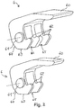
- Connection terminal 9 shown is constructed essentially symmetrically with respect to a vertical axis of symmetry. It has a first spring clamp connection 1 and a second spring clamp connection 2 on the left and right of the vertical axis of symmetry.
- the first and the second spring terminal connection 1, 2 are arranged in an insulating material housing 4, 5 of the connecting terminal 9.
- the insulating material housing 4, 5 can be formed, for example, at least in two parts, for example from an upper housing part 4 and a bottom part 5 which can be connected to the upper housing part 4 by means of latching elements 50.
- the first spring-loaded terminal connection 1 has a first clamping spring 11 that is bent several times in the form of a loop.
- the first clamping spring 11 has at one end a clamping leg 12 which is used to clamp an electrical conductor inserted through a first conductor insertion opening 10 against a first clamping point 31 of a busbar 3.
- a spring arch 14 adjoins the clamping leg 12 of the first clamping spring 11, to which a contact leg 15 of the first clamping spring 11 then connects.
- the contact leg 15 lies against an inner wall region 41 of the insulating material housing 4, 5 and is supported on it at least in part with respect to the forces absorbed by the clamping leg 12.
- the first clamping spring 11 extends further in the region of the contact leg 15 into an extended end section 16, in which the material of the first clamping spring 11 is finally bent in a vertical region 17 in the direction of the busbar 3.
- the end section 16 of the contact leg 15 extends beyond the vertical region 17 further downward through a through opening 30 of the busbar 3 and is finally suspended in the through opening 30 of the busbar 3, e.g. in that an end piece 18 of the end section 16 is further angled and thus engages behind the busbar 3, in particular in a region of the busbar 3 designed as a nozzle 33, which surrounds the through opening 30 in a base shape.
- the second clamping spring 21 can, for example, be shaped in the same way as the first clamping spring 11.
- the second spring-force clamping connection 2 has a second clamping spring 21 that is bent several times in a loop.
- the second clamping spring 21 has a clamping leg 22 at one end, which serves to clamp an electrical conductor inserted through a second conductor insertion opening 20 against a second clamping point 32 of the busbar 3.
- an actuation area 23 of the second clamping spring 21 on which the clamping leg 22 can be actuated via an actuating lever 29 for opening and closing the second spring-loaded terminal connection 2.
- a spring arch 24 adjoins the clamping leg 22 of the second clamping spring 21, to which a contact leg 25 of the second clamping spring 21 then connects.
- the contact leg 25 bears against an inner wall area 42 of the insulating material housing 4, 5 and is supported on it at least in part against the forces absorbed by the clamping leg 22.
- the second clamping spring 21 extends in the region of the contact leg 25 further into an extended end section 26, in which the material of the second clamping spring 21 finally in one Vertical region 27 is bent in the direction of the busbar 3.
- the end section 26 of the contact leg 25 extends beyond the vertical region 27 further downward through the through opening 30 of the busbar 3 and is finally hooked into the through opening 30 of the busbar 3, for example by an end piece 28 of the end section 26 being angled further and thus the busbar 3 engages behind, in particular in the area of the busbar 3 designed as a nozzle 33.
- the Figure 1 shows the first spring-loaded terminal connection 1 with the first actuating lever 19 open, such that the first clamping point 31 is not touched by the clamping leg 12 and an electrical conductor which may have been previously clamped there can be removed. It can be seen that the clamping leg 12 of the first clamping spring 11 is then removed from the first clamping point 31.
- the second spring-loaded terminal connection 2 is shown in the closed state, ie the second actuating lever 29 is in the closed position. In this state, the clamping leg 22 of the second clamping spring 21 touches the end of the second clamping point 32 of the busbar 3.
- the busbar 3 has impressions in the region of its first and second clamping points 31, 32, through which the material of the busbar 3 goes upwards, i.e. something in the direction of the respective clamping leg 12, 22 is exposed. This improves the clamping of a connected electrical conductor.
- the busbar 3 is formed in one piece as a flat, short busbar piece. By designing the through opening 30 with the nozzle 33, the busbar 3 is mechanically stabilized in this area and also optimized with regard to the electrical line.
- the clamping springs 11, 21 cannot initially be bent outward in their respective end pieces 18, 28, ie before they are fastened to the busbar 3, as in FIG Figure 1 is recognizable. They can initially run essentially in a straight line. After the clamping springs 11, 21 have been installed in the through opening 30 of the busbar 3, a further production step takes place in that the end pieces 18, 28 are bent outwards, ie in the direction of the respective conductor insertion opening 10, 20, and then engage behind the nozzle 33.
- the first clamping spring 11 is supported in the vertical region 17 on the vertical region 27 of the second clamping spring 21, i.e. the clamping springs 11, 21 are mutually supported in the region of their vertical sections 17, 27.
- the vertical region 17 also forms a conductor stop when the first conductor is inserted into the insulating material housing.
- the vertical region 27 also forms a conductor stop when the second conductor is inserted into the insulating material housing.
- the connecting clamp 9 can be designed as a simple connecting clamp, in which there is a conductor insertion opening 10, 20 on each side. It can also be designed as a double or multiple terminal. In this case, two or more first conductor insertion openings 10 and two or more second conductor insertion openings 20 are arranged side by side on each side available. A different configuration of the respective actuating lever 19, 29 can be advantageous for such embodiments.
- the Figure 2 shows in the lower area an advantageous embodiment of an actuating lever 6, which can be used as the first or second actuating lever 19, 29, in the event that the connecting terminal has only one conductor insertion opening 10, 20 on each side.
- the operating lever 6 has a manual operating area 60 (handle area), on which the operating lever 6 can be operated by a user.
- the actuating lever 6 also has a bearing axis 61, by means of which it can be used to mount insulating material housings 4, 5.
- the actuating lever 6 is fork-shaped in the region of the bearing axis 61, with a region 65 which is recessed in the middle and by means of which the actuating lever 6 can be placed over the clamping spring lying in between.
- the clamping spring then has laterally projecting areas 13 and 23, on which the clamping spring can be acted upon by actuating areas 62 of the actuating lever 6.
- a rear contour of the actuating lever 6 has two bearing regions 63, 64 arranged at an angle to one another, via which the actuating lever is supported in the insulating material housing and / or on the busbar 3. In the closed actuation position, the actuation lever 6 rests with the bearing region 63, in the open position with the bearing region 64.
- the bearing axis 61 is received in a groove (not shown) arranged in the housing upper part 4 and oriented essentially perpendicular to the busbar 3 through the bearing areas 63, 64, which slide on the busbar 3 during the pivoting movement of the actuating lever 19, 29, to be able to accommodate conditional deflection occurring during the pivoting movement of the actuating lever 19, 29.
- the Figure 2 shows in the upper area an embodiment of an actuating lever 6, which is designed for a connecting terminal, in which there are two spring-loaded terminal connections arranged side by side on each housing side. Accordingly, the entire actuating lever 6 is made wider and has two recessed areas 65 lying next to one another, in which respective clamping springs can be passed. The corresponding three exposure areas 62 provided. Here, the middle loading area 62 acts simultaneously on the two adjacent clamping springs on one side of the connecting terminal 9.
- the Figure 3 shows in an enlarged detail the attachment of the clamping springs on the busbar 3.
- a double clamping spring which has two juxtaposed contact legs and clamping legs and is thus designed for a connecting clamp, in which there are two spring-cage clamp connections arranged next to each other on the housing side.
- a partial section of the respective vertical regions 27 of the clamping springs is shown here. These then unite to form a common fastening section 271, which is finally fastened to the nozzle 33 of the busbar 3 via the end pieces 28 which are guided through the through opening 30.
- the left end piece 28 has already been bent over, as in FIG Figure 1 shown, and the right end piece 28 is not yet bent.
- the clamping spring rests on the busbar 3 with contact surfaces 270.
- the Figure 4 shows an enlarged detailed view of a possible shape of the busbar 3 in the area of the passage opening 30.
- the passage opening 30 does not have to be circular, for example, but, as shown, can be essentially rectangular with rounded corners. Accordingly, the wall area of the nozzle 33 surrounds this through opening 30.
- connection terminal 9 corresponds in its essential structure to that previously based on the Figures 1 to 4 explained connection terminal 9. Therefore, the differences are essentially discussed below.
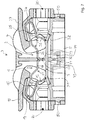
- FIG. 5 shows, are in the double connection terminal 9 on each conductor insertion side, two adjacent conductor insertion openings 10, 20 available. In the closed position, for example, the clamping legs 22 are visible when looking into the conductor insertion openings 20.
- the Figure 6 shows a comparable operating lever 6, as in Figure 2 shown in the figure above.
- the operating lever according to Figure 6 can be used as an operating lever 19 and 29, as in the Figure 7 can be seen.
- the busbar 3 also has a through opening 30 which, however, is formed here without the nozzle 33.
- the vertical regions 17, 27 of the end sections 16, 26 of the clamping springs 11, 21 also protrude through the through opening 30 in this embodiment.
- the vertical regions 17, 27 do not end in further angled end pieces 18, 28 as in the embodiment explained first. Instead, they run in straight end pieces 71, 72 further in the vertical direction.
- respective material areas 73, 74 which are exposed in the sense of a latch or barb, are provided on the end pieces 71, 72.
- the material areas 73, 74 can be deflected resiliently, so that the clamping springs 11, 21 in the illustrated back-to-back configuration with the end pieces 71, 72 can be inserted through the openings 30 of the busbar 3.
- the material areas 73, 74 initially deflect. If this plug-in process is carried out, the material areas 73, 74 spring out again and engage behind the busbar 3 and thus fix the clamping springs 11, 21 on the busbar 3.
- each clamping spring 11 it is possible for each clamping spring 11 to have its own end piece 71, 72 with an exposed material area 73, 74. This is also necessary for a single connection terminal. In the double connection terminal 9 described here, this can also be implemented in such a way that the clamping springs are formed independently of one another by respective end pieces 71, 72 with projecting material areas 73, 74 arranged thereon.
- adjacent clamping springs lying next to one another can also be formed via a common end piece 71 or 72, each with a protruding material region 73 or 74.
- the vertical regions 17, 27 can each be made wider, so that they extend continuously from one to the other arranged clamping spring.
- FIG. 8 and 9 additionally clarifies in which the contact insert formed by the busbar 3 and the clamping springs 11, 21 is shown separately.
- two clamping springs 11 and 21, which are arranged next to one another, are connected to one another via a common vertical region 17 and 27, which is continuous in width, and are fastened to the busbar 3.
- Each vertical region 17, 27 has, for. B. at a central point, the mentioned, through the through opening 30 of the busbar 3 end piece 71 or 72 with the arranged, serving for fixing exposed material area 73 or 74 on.
- the side-by-side clamping springs 11 and 21 can be actuated independently of one another, i. H. they are not connected to one another in the other areas, beyond the common vertical areas 17 and 27.
- connection terminal or double connection terminal 9 can also be designed as a multiple connection terminal, in which there are more than two clamping points arranged next to one another on each conductor insertion side, for. B. 3, 4, 5 or more.
- a common through opening can be present in the conductor rail for groups of clamping springs or for all the clamping springs for fixing them to the conductor rail.
- the Figure 10 shows a view of the underside of the upper housing part 4 of the double connection terminal 9, ie to the side on which the lower housing part is mounted.
- the Figure 11 shows the upper housing part 4 according to the in Figure 10 shown Section plane BB of the double connection clamp.
- grooves 41, 42 can be seen in the side walls for receiving and mounting the actuating levers 19, 29, each of which can be inserted with their bearing axes 61 into the grooves 41, 42 from below, and then at the upper end of the respective groove 41, 42 to be stored and kept.
- the respective grooves 41, 42 extend from the underside of the upper housing part 4 to a position above the respective conductor insertion opening 10, 20.
Landscapes
- Connections Arranged To Contact A Plurality Of Conductors (AREA)
- Coupling Device And Connection With Printed Circuit (AREA)
- Details Of Connecting Devices For Male And Female Coupling (AREA)
- Multi-Conductor Connections (AREA)
- Clamps And Clips (AREA)
- Installation Of Bus-Bars (AREA)
Priority Applications (1)
| Application Number | Priority Date | Filing Date | Title |
|---|---|---|---|
| PL19204886T PL3627625T3 (pl) | 2015-11-09 | 2016-11-08 | Zacisk przyłączeniowy |
Applications Claiming Priority (3)
| Application Number | Priority Date | Filing Date | Title |
|---|---|---|---|
| DE102015119247.0A DE102015119247A1 (de) | 2015-11-09 | 2015-11-09 | Verbindungsklemme |
| EP16794300.0A EP3375045B1 (fr) | 2015-11-09 | 2016-11-08 | Borne de connexion |
| PCT/EP2016/076973 WO2017081001A1 (fr) | 2015-11-09 | 2016-11-08 | Borne de connexion |
Related Parent Applications (2)
| Application Number | Title | Priority Date | Filing Date |
|---|---|---|---|
| EP16794300.0A Division EP3375045B1 (fr) | 2015-11-09 | 2016-11-08 | Borne de connexion |
| EP16794300.0A Division-Into EP3375045B1 (fr) | 2015-11-09 | 2016-11-08 | Borne de connexion |
Publications (2)
| Publication Number | Publication Date |
|---|---|
| EP3627625A1 true EP3627625A1 (fr) | 2020-03-25 |
| EP3627625B1 EP3627625B1 (fr) | 2021-09-01 |
Family
ID=57281208
Family Applications (2)
| Application Number | Title | Priority Date | Filing Date |
|---|---|---|---|
| EP16794300.0A Active EP3375045B1 (fr) | 2015-11-09 | 2016-11-08 | Borne de connexion |
| EP19204886.6A Active EP3627625B1 (fr) | 2015-11-09 | 2016-11-08 | Borne de raccordement |
Family Applications Before (1)
| Application Number | Title | Priority Date | Filing Date |
|---|---|---|---|
| EP16794300.0A Active EP3375045B1 (fr) | 2015-11-09 | 2016-11-08 | Borne de connexion |
Country Status (10)
| Country | Link |
|---|---|
| US (1) | US10164349B2 (fr) |
| EP (2) | EP3375045B1 (fr) |
| JP (1) | JP6808167B2 (fr) |
| KR (1) | KR102607068B1 (fr) |
| CN (2) | CN108352627B (fr) |
| DE (1) | DE102015119247A1 (fr) |
| ES (1) | ES2780698T3 (fr) |
| PL (2) | PL3375045T3 (fr) |
| RU (1) | RU2715558C1 (fr) |
| WO (1) | WO2017081001A1 (fr) |
Families Citing this family (40)
| Publication number | Priority date | Publication date | Assignee | Title |
|---|---|---|---|---|
| DE102016111627A1 (de) | 2016-06-24 | 2017-12-28 | Wago Verwaltungsgesellschaft Mbh | Leiteranschlussklemme |
| DE102016115490B4 (de) * | 2016-08-22 | 2018-06-07 | Harting Electric Gmbh & Co. Kg | Anschlusselement |
| DE102016116966A1 (de) | 2016-09-09 | 2018-03-15 | Wago Verwaltungsgesellschaft Mbh | Federkraftklemmanschluss sowie Leiteranschlussklemme |
| CN108075252B (zh) * | 2017-07-12 | 2023-08-01 | 安波福中央电气(上海)有限公司 | 电连接器 |
| BE1025389B1 (de) * | 2017-07-14 | 2019-02-12 | Phoenix Contact Gmbh & Co. Kg | ANSCHLUSSEINRICHTUNG ZUM ANSCHLIEßEN EINER ELEKTRISCHEN LEITUNG |
| DE202017105467U1 (de) | 2017-09-08 | 2018-12-12 | Wago Verwaltungsgesellschaft Mbh | Leiteranschlussklemme |
| DE102017130389A1 (de) * | 2017-12-18 | 2019-06-19 | KL UG (haftungsbeschränkt) | Vorrichtung zum Herstellen einer elektrischen Verbindung |
| DE202018101727U1 (de) * | 2018-03-28 | 2019-07-01 | Wago Verwaltungsgesellschaft Mbh | Leiteranschlussklemme, Klemmfeder einer Leiteranschlussklemme sowie Reihenklemme |
| DE202018101732U1 (de) * | 2018-03-28 | 2019-07-01 | Wago Verwaltungsgesellschaft Mbh | Leiteranschlussklemme, Klemmfeder einer Leiteranschlussklemme sowie Reihenklemme |
| DE202018101731U1 (de) * | 2018-03-28 | 2019-07-01 | Wago Verwaltungsgesellschaft Mbh | Leiteranschlussklemme, Klemmfeder einer Leiteranschlussklemme sowie Reihenklemme |
| DE202018101734U1 (de) * | 2018-03-28 | 2019-07-01 | Wago Verwaltungsgesellschaft Mbh | Leiteranschlussklemme, Klemmfeder einer Leiteranschlussklemme sowie Reihenklemme |
| CN111919342B (zh) | 2018-03-28 | 2022-08-30 | Wago管理有限责任公司 | 接线端子,接线端子的夹紧弹簧以及轨装式端子 |
| DE202018102026U1 (de) * | 2018-04-13 | 2019-07-17 | Weidmüller Interface GmbH & Co. KG | Anschlussklemme und Potentialverteilerstecker |
| USD914613S1 (en) * | 2018-04-19 | 2021-03-30 | Wago Verwaltungsgesellschaft Mbh | Electric terminal |
| DE102018117508B4 (de) * | 2018-07-19 | 2024-01-18 | Wago Verwaltungsgesellschaft Mbh | Leiteranschlussklemme |
| CN109149152B (zh) * | 2018-09-11 | 2020-09-01 | 余姚市信亿电子科技有限公司 | 一种导线连接器 |
| DE102018124623B4 (de) * | 2018-10-05 | 2022-07-07 | Wago Verwaltungsgesellschaft Mbh | Kontakteinsatz einer Leiteranschlussklemme sowie damit gebildete Leiteranschlussklemme |
| DE202018004944U1 (de) * | 2018-10-25 | 2020-01-28 | Electro Terminal Gmbh & Co Kg | Reihensteckklemme |
| US10418727B1 (en) * | 2018-11-15 | 2019-09-17 | Dinkle Enterprise Co., Ltd. | Rotate-to-open clamping unit and connection device having the same |
| DE202018106896U1 (de) * | 2018-12-04 | 2020-03-05 | WAGO Verwaltungsgesellschaft mit beschränkter Haftung | Federanschlussklemme |
| US10511108B1 (en) * | 2019-01-07 | 2019-12-17 | Dinkle Enterprise Co., Ltd. | Dual-wire connector |
| US11495895B2 (en) * | 2019-05-01 | 2022-11-08 | Hubbell Incorporated | Terminations for electrical wiring devices |
| DE202019103271U1 (de) * | 2019-06-11 | 2020-09-16 | Wago Verwaltungsgesellschaft Mbh | Leiteranschlussklemme, Sortiment aus wenigstens einem Basismodul und unterschiedlich ausgebildeten Leiteranschlussmodulen einer Leiteranschlussklemme und Leiteranschlussklemmenblock |
| DE102019117301A1 (de) * | 2019-06-27 | 2020-12-31 | Phoenix Contact Gmbh & Co. Kg | Anschlussklemme |
| DE102019117302A1 (de) * | 2019-06-27 | 2020-12-31 | Phoenix Contact Gmbh & Co. Kg | Anschlussklemmenanordnung zum Anschließen mindestens eines elektrischen Leiters |
| DE102019132007A1 (de) * | 2019-11-26 | 2021-05-27 | Phoenix Contact Gmbh & Co. Kg | Anschlussklemme sowie elektronisches Gerät |
| DE102020100218A1 (de) * | 2020-01-08 | 2021-07-08 | WAGO Verwaltungsgesellschaft mit beschränkter Haftung | Leiteranschlussklemme |
| DE202020100088U1 (de) * | 2020-01-09 | 2021-04-12 | Wago Verwaltungsgesellschaft Mbh | Leiteranschlussklemme |
| DE202020100089U1 (de) | 2020-01-09 | 2021-04-12 | Wago Verwaltungsgesellschaft Mbh | Leiteranschlussklemme |
| DE102020104080C5 (de) | 2020-02-17 | 2022-05-05 | WAGO Verwaltungsgesellschaft mit beschränkter Haftung | Leiteranschlussklemme und Verfahren zur Montage einer Leiteranschlussklemme |
| DE102020104077A1 (de) * | 2020-02-17 | 2021-08-19 | WAGO Verwaltungsgesellschaft mit beschränkter Haftung | Federkraftklemmanschluss |
| JP7399570B2 (ja) * | 2020-03-19 | 2023-12-18 | 日東工業株式会社 | 端子構造 |
| CN115769440A (zh) * | 2020-06-18 | 2023-03-07 | 理想工业公司 | 导体端子 |
| DE102020120151A1 (de) * | 2020-07-30 | 2022-02-03 | WAGO Verwaltungsgesellschaft mit beschränkter Haftung | Verbindungsklemme zum Verbinden elektrischer Leiter |
| US11217913B1 (en) * | 2020-08-18 | 2022-01-04 | Dinkle Enterprise Co., Ltd. | Terminal block with handle |
| CN112736500B (zh) * | 2020-12-25 | 2022-04-19 | 宁波速普电子有限公司 | 一种设有分级释放手柄的接线端子 |
| DE202021101354U1 (de) | 2021-03-17 | 2022-06-22 | Wago Verwaltungsgesellschaft Mbh | Leiteranschlussklemme und elektrischer Steckverbinder |
| EP4089857A1 (fr) * | 2021-05-13 | 2022-11-16 | Heavy Power Co., Ltd. | Connecteur de câble de type came |
| US11670878B2 (en) * | 2021-05-18 | 2023-06-06 | Dinkle Enterprise Co., Ltd. | Terminal block structure |
| DE102022109238A1 (de) | 2022-04-14 | 2023-10-19 | Harting Electric Stiftung & Co. Kg | Kontaktträger, Steckverbindereinsatz und Steckverbinder |
Citations (2)
| Publication number | Priority date | Publication date | Assignee | Title |
|---|---|---|---|---|
| EP2605335A2 (fr) * | 2011-12-14 | 2013-06-19 | Wago Verwaltungsgesellschaft mbH | Borne de connexion |
| DE102013101830A1 (de) | 2013-01-08 | 2014-07-10 | Wago Verwaltungsgesellschaft Mbh | Elektrische Anschlussklemme und Verfahren zu dessen Montage |
Family Cites Families (19)
| Publication number | Priority date | Publication date | Assignee | Title |
|---|---|---|---|---|
| US3596229A (en) * | 1969-04-28 | 1971-07-27 | Wago Kontakttechnik Gmbh | Electrical connector |
| JPH09147931A (ja) * | 1995-11-17 | 1997-06-06 | Tec Corp | 電線接続装置 |
| DE10134417C1 (de) * | 2001-07-19 | 2003-01-23 | Phoenix Contact Gmbh & Co | Elektrische Anschluß- oder Verbindungseinrichtung |
| DE10315668B4 (de) | 2002-08-28 | 2007-06-06 | Conrad Stanztechnik Gmbh | Anschlußklemme |
| DE10355195B4 (de) | 2003-11-26 | 2007-03-15 | Wieland Electric Gmbh | Leiteranschluss |
| RU2253929C1 (ru) * | 2003-12-08 | 2005-06-10 | Деревенко Андрей Константинович | Соединитель электрических проводов |
| DE102006019150B4 (de) * | 2006-04-21 | 2011-06-09 | Wago Verwaltungsgesellschaft Mbh | Elektrische Verbindungsklemme |
| DE112007003439A5 (de) * | 2007-02-07 | 2010-01-21 | Siemens Aktiengesellschaft | Elektrisches Gerät und Geräteanordnung |
| DE102007050683B4 (de) * | 2007-10-22 | 2009-09-03 | Wago Verwaltungsgesellschaft Mbh | Leiteranschlussklemme |
| DE102007051697B4 (de) * | 2007-10-26 | 2021-10-28 | Phoenix Contact Gmbh & Co. Kg | Anschlussklemme mit Öffnungseinrichtung |
| RU2375794C1 (ru) * | 2008-02-18 | 2009-12-10 | Деревенко Андрей Константинович | Соединитель электрических проводов (варианты) |
| ITMI20080673A1 (it) * | 2008-04-15 | 2009-10-16 | Morsettitalia Spa | Elemento elastico per la trattenuta di fili elettrici e morsetto comprendente tale elemento elastico |
| US7976330B2 (en) * | 2009-08-28 | 2011-07-12 | K.S. Terminals Inc. | Securely latched power connector assembly |
| RU2421854C1 (ru) * | 2010-03-29 | 2011-06-20 | Андрей Константинович Деревенко | Соединитель электрических проводов |
| DE102010048698B4 (de) | 2010-10-19 | 2014-12-18 | Wago Verwaltungsgesellschaft Mbh | Elektrische Verbindungsklemme |
| CN202308345U (zh) * | 2011-10-28 | 2012-07-04 | 江门市创艺电器有限公司 | 一种新型接线端子 |
| DE102012011794A1 (de) | 2012-06-15 | 2013-12-19 | Phoenix Contact Gmbh & Co. Kg | Elektrische Anschlussklemme |
| DE102013000713A1 (de) * | 2013-01-17 | 2014-07-17 | Phoenix Contact Gmbh & Co. Kg | Anschlussklemme |
| DE102014119421B4 (de) * | 2014-12-22 | 2017-02-02 | Wago Verwaltungsgesellschaft Mbh | Verbindungsklemme und Verfahren zur Montage einer Verbindungsklemme |
-
2015
- 2015-11-09 DE DE102015119247.0A patent/DE102015119247A1/de active Pending
-
2016
- 2016-11-08 EP EP16794300.0A patent/EP3375045B1/fr active Active
- 2016-11-08 PL PL16794300T patent/PL3375045T3/pl unknown
- 2016-11-08 KR KR1020187011691A patent/KR102607068B1/ko active IP Right Grant
- 2016-11-08 RU RU2018116442A patent/RU2715558C1/ru active
- 2016-11-08 JP JP2018521540A patent/JP6808167B2/ja active Active
- 2016-11-08 PL PL19204886T patent/PL3627625T3/pl unknown
- 2016-11-08 EP EP19204886.6A patent/EP3627625B1/fr active Active
- 2016-11-08 ES ES16794300T patent/ES2780698T3/es active Active
- 2016-11-08 CN CN201680062466.1A patent/CN108352627B/zh active Active
- 2016-11-08 WO PCT/EP2016/076973 patent/WO2017081001A1/fr active Application Filing
- 2016-11-08 CN CN201911064675.1A patent/CN110854555B/zh active Active
-
2018
- 2018-05-08 US US15/974,119 patent/US10164349B2/en active Active
Patent Citations (2)
| Publication number | Priority date | Publication date | Assignee | Title |
|---|---|---|---|---|
| EP2605335A2 (fr) * | 2011-12-14 | 2013-06-19 | Wago Verwaltungsgesellschaft mbH | Borne de connexion |
| DE102013101830A1 (de) | 2013-01-08 | 2014-07-10 | Wago Verwaltungsgesellschaft Mbh | Elektrische Anschlussklemme und Verfahren zu dessen Montage |
Also Published As
| Publication number | Publication date |
|---|---|
| PL3375045T3 (pl) | 2020-07-27 |
| CN110854555B (zh) | 2021-04-27 |
| JP2018533185A (ja) | 2018-11-08 |
| EP3375045A1 (fr) | 2018-09-19 |
| ES2780698T3 (es) | 2020-08-26 |
| CN110854555A (zh) | 2020-02-28 |
| US10164349B2 (en) | 2018-12-25 |
| RU2715558C1 (ru) | 2020-03-02 |
| US20180254568A1 (en) | 2018-09-06 |
| DE102015119247A1 (de) | 2017-05-11 |
| EP3627625B1 (fr) | 2021-09-01 |
| PL3627625T3 (pl) | 2021-12-20 |
| EP3375045B1 (fr) | 2020-02-26 |
| KR102607068B1 (ko) | 2023-11-29 |
| JP6808167B2 (ja) | 2021-01-06 |
| WO2017081001A1 (fr) | 2017-05-18 |
| KR20180078239A (ko) | 2018-07-09 |
| CN108352627A (zh) | 2018-07-31 |
| CN108352627B (zh) | 2019-12-03 |
Similar Documents
| Publication | Publication Date | Title |
|---|---|---|
| EP3375045B1 (fr) | Borne de connexion | |
| EP2605335B2 (fr) | Borne de connexion | |
| EP3454422B2 (fr) | Borne de connexion conductrice | |
| EP2351152A1 (fr) | Borne de raccordement pour le raccordement d'une extrémité de conducteur | |
| WO2021105280A1 (fr) | Borne à ressorts de conducteur | |
| EP3843221A1 (fr) | Cadre de support pour un connecteur | |
| EP2614556B1 (fr) | Dispositif de raccordement | |
| AT517769B1 (de) | Energiezähler-Anschlussklemmenblock mit Überbrückungsvorrichtung | |
| DE10237701A1 (de) | Verbindungsklemme für ein-, mehrdrähtige, insbesondere feindrähtige, elektrische Leiter | |
| EP3982486A1 (fr) | Pince pourvue de levier de déblocage | |
| EP3038213B1 (fr) | Borne de connection de cable destinee a serrer au moins un conducteur electrique | |
| AT501539A1 (de) | Bauteil zum raschen verbinden von enden | |
| EP0921611B1 (fr) | Prise et interrupteur pour le secteur | |
| DE102018101381A1 (de) | Steckverbinder mit Federkontakt | |
| EP1845593B1 (fr) | Matière articulée pour lampes à décharge pour serres | |
| DE69908284T2 (de) | Unterputzdose für ein elektrisches Gerät | |
| WO2010124792A1 (fr) | Appareil de commutation pour installation et procédé de montage de celui-ci | |
| EP2920852A1 (fr) | Insert de prise | |
| EP1505701A1 (fr) | Dispositif électrique à monter sur barres omnibus | |
| DE102020115991B4 (de) | Leiteranschlussklemme mit Betätigung durch ein Leiteranschlussmodul | |
| EP1253610B1 (fr) | Adaptateur pour contacter des sectionneurs de coupure en charge sur barres omnibus | |
| DE2434577A1 (de) | Elektrisches installationsgeraet | |
| DE202022102833U1 (de) | Klemme mit Lösehebel und Drücker | |
| DE202010007680U1 (de) | DIN-Schienenverteiler | |
| DE102020126486A1 (de) | Halterahmen für einen Steckverbinder |
Legal Events
| Date | Code | Title | Description |
|---|---|---|---|
| PUAI | Public reference made under article 153(3) epc to a published international application that has entered the european phase |
Free format text: ORIGINAL CODE: 0009012 |
|
| STAA | Information on the status of an ep patent application or granted ep patent |
Free format text: STATUS: REQUEST FOR EXAMINATION WAS MADE |
|
| 17P | Request for examination filed |
Effective date: 20191023 |
|
| AC | Divisional application: reference to earlier application |
Ref document number: 3375045 Country of ref document: EP Kind code of ref document: P |
|
| AK | Designated contracting states |
Kind code of ref document: A1 Designated state(s): AL AT BE BG CH CY CZ DE DK EE ES FI FR GB GR HR HU IE IS IT LI LT LU LV MC MK MT NL NO PL PT RO RS SE SI SK SM TR |
|
| STAA | Information on the status of an ep patent application or granted ep patent |
Free format text: STATUS: EXAMINATION IS IN PROGRESS |
|
| RIN1 | Information on inventor provided before grant (corrected) |
Inventor name: KOELLMANN, HANS-JOSEF Inventor name: MEYER, MICHAEL |
|
| 17Q | First examination report despatched |
Effective date: 20210129 |
|
| GRAP | Despatch of communication of intention to grant a patent |
Free format text: ORIGINAL CODE: EPIDOSNIGR1 |
|
| STAA | Information on the status of an ep patent application or granted ep patent |
Free format text: STATUS: GRANT OF PATENT IS INTENDED |
|
| GRAJ | Information related to disapproval of communication of intention to grant by the applicant or resumption of examination proceedings by the epo deleted |
Free format text: ORIGINAL CODE: EPIDOSDIGR1 |
|
| STAA | Information on the status of an ep patent application or granted ep patent |
Free format text: STATUS: EXAMINATION IS IN PROGRESS |
|
| INTG | Intention to grant announced |
Effective date: 20210412 |
|
| INTC | Intention to grant announced (deleted) | ||
| GRAP | Despatch of communication of intention to grant a patent |
Free format text: ORIGINAL CODE: EPIDOSNIGR1 |
|
| STAA | Information on the status of an ep patent application or granted ep patent |
Free format text: STATUS: GRANT OF PATENT IS INTENDED |
|
| INTG | Intention to grant announced |
Effective date: 20210611 |
|
| GRAS | Grant fee paid |
Free format text: ORIGINAL CODE: EPIDOSNIGR3 |
|
| GRAA | (expected) grant |
Free format text: ORIGINAL CODE: 0009210 |
|
| STAA | Information on the status of an ep patent application or granted ep patent |
Free format text: STATUS: THE PATENT HAS BEEN GRANTED |
|
| AC | Divisional application: reference to earlier application |
Ref document number: 3375045 Country of ref document: EP Kind code of ref document: P |
|
| AK | Designated contracting states |
Kind code of ref document: B1 Designated state(s): AL AT BE BG CH CY CZ DE DK EE ES FI FR GB GR HR HU IE IS IT LI LT LU LV MC MK MT NL NO PL PT RO RS SE SI SK SM TR |
|
| REG | Reference to a national code |
Ref country code: GB Ref legal event code: FG4D Free format text: NOT ENGLISH |
|
| REG | Reference to a national code |
Ref country code: CH Ref legal event code: EP Ref country code: AT Ref legal event code: REF Ref document number: 1427189 Country of ref document: AT Kind code of ref document: T Effective date: 20210915 |
|
| REG | Reference to a national code |
Ref country code: DE Ref legal event code: R096 Ref document number: 502016013771 Country of ref document: DE |
|
| REG | Reference to a national code |
Ref country code: IE Ref legal event code: FG4D Free format text: LANGUAGE OF EP DOCUMENT: GERMAN |
|
| REG | Reference to a national code |
Ref country code: LT Ref legal event code: MG9D |
|
| REG | Reference to a national code |
Ref country code: NL Ref legal event code: MP Effective date: 20210901 |
|
| PG25 | Lapsed in a contracting state [announced via postgrant information from national office to epo] |
Ref country code: SE Free format text: LAPSE BECAUSE OF FAILURE TO SUBMIT A TRANSLATION OF THE DESCRIPTION OR TO PAY THE FEE WITHIN THE PRESCRIBED TIME-LIMIT Effective date: 20210901 Ref country code: RS Free format text: LAPSE BECAUSE OF FAILURE TO SUBMIT A TRANSLATION OF THE DESCRIPTION OR TO PAY THE FEE WITHIN THE PRESCRIBED TIME-LIMIT Effective date: 20210901 Ref country code: ES Free format text: LAPSE BECAUSE OF FAILURE TO SUBMIT A TRANSLATION OF THE DESCRIPTION OR TO PAY THE FEE WITHIN THE PRESCRIBED TIME-LIMIT Effective date: 20210901 Ref country code: FI Free format text: LAPSE BECAUSE OF FAILURE TO SUBMIT A TRANSLATION OF THE DESCRIPTION OR TO PAY THE FEE WITHIN THE PRESCRIBED TIME-LIMIT Effective date: 20210901 Ref country code: HR Free format text: LAPSE BECAUSE OF FAILURE TO SUBMIT A TRANSLATION OF THE DESCRIPTION OR TO PAY THE FEE WITHIN THE PRESCRIBED TIME-LIMIT Effective date: 20210901 Ref country code: NO Free format text: LAPSE BECAUSE OF FAILURE TO SUBMIT A TRANSLATION OF THE DESCRIPTION OR TO PAY THE FEE WITHIN THE PRESCRIBED TIME-LIMIT Effective date: 20211201 Ref country code: BG Free format text: LAPSE BECAUSE OF FAILURE TO SUBMIT A TRANSLATION OF THE DESCRIPTION OR TO PAY THE FEE WITHIN THE PRESCRIBED TIME-LIMIT Effective date: 20211201 Ref country code: LT Free format text: LAPSE BECAUSE OF FAILURE TO SUBMIT A TRANSLATION OF THE DESCRIPTION OR TO PAY THE FEE WITHIN THE PRESCRIBED TIME-LIMIT Effective date: 20210901 |
|
| PG25 | Lapsed in a contracting state [announced via postgrant information from national office to epo] |
Ref country code: LV Free format text: LAPSE BECAUSE OF FAILURE TO SUBMIT A TRANSLATION OF THE DESCRIPTION OR TO PAY THE FEE WITHIN THE PRESCRIBED TIME-LIMIT Effective date: 20210901 Ref country code: GR Free format text: LAPSE BECAUSE OF FAILURE TO SUBMIT A TRANSLATION OF THE DESCRIPTION OR TO PAY THE FEE WITHIN THE PRESCRIBED TIME-LIMIT Effective date: 20211202 |
|
| PG25 | Lapsed in a contracting state [announced via postgrant information from national office to epo] |
Ref country code: IS Free format text: LAPSE BECAUSE OF FAILURE TO SUBMIT A TRANSLATION OF THE DESCRIPTION OR TO PAY THE FEE WITHIN THE PRESCRIBED TIME-LIMIT Effective date: 20220101 Ref country code: SM Free format text: LAPSE BECAUSE OF FAILURE TO SUBMIT A TRANSLATION OF THE DESCRIPTION OR TO PAY THE FEE WITHIN THE PRESCRIBED TIME-LIMIT Effective date: 20210901 Ref country code: SK Free format text: LAPSE BECAUSE OF FAILURE TO SUBMIT A TRANSLATION OF THE DESCRIPTION OR TO PAY THE FEE WITHIN THE PRESCRIBED TIME-LIMIT Effective date: 20210901 Ref country code: RO Free format text: LAPSE BECAUSE OF FAILURE TO SUBMIT A TRANSLATION OF THE DESCRIPTION OR TO PAY THE FEE WITHIN THE PRESCRIBED TIME-LIMIT Effective date: 20210901 Ref country code: PT Free format text: LAPSE BECAUSE OF FAILURE TO SUBMIT A TRANSLATION OF THE DESCRIPTION OR TO PAY THE FEE WITHIN THE PRESCRIBED TIME-LIMIT Effective date: 20220103 Ref country code: NL Free format text: LAPSE BECAUSE OF FAILURE TO SUBMIT A TRANSLATION OF THE DESCRIPTION OR TO PAY THE FEE WITHIN THE PRESCRIBED TIME-LIMIT Effective date: 20210901 Ref country code: EE Free format text: LAPSE BECAUSE OF FAILURE TO SUBMIT A TRANSLATION OF THE DESCRIPTION OR TO PAY THE FEE WITHIN THE PRESCRIBED TIME-LIMIT Effective date: 20210901 Ref country code: CZ Free format text: LAPSE BECAUSE OF FAILURE TO SUBMIT A TRANSLATION OF THE DESCRIPTION OR TO PAY THE FEE WITHIN THE PRESCRIBED TIME-LIMIT Effective date: 20210901 Ref country code: AL Free format text: LAPSE BECAUSE OF FAILURE TO SUBMIT A TRANSLATION OF THE DESCRIPTION OR TO PAY THE FEE WITHIN THE PRESCRIBED TIME-LIMIT Effective date: 20210901 |
|
| REG | Reference to a national code |
Ref country code: DE Ref legal event code: R097 Ref document number: 502016013771 Country of ref document: DE |
|
| PG25 | Lapsed in a contracting state [announced via postgrant information from national office to epo] |
Ref country code: MC Free format text: LAPSE BECAUSE OF FAILURE TO SUBMIT A TRANSLATION OF THE DESCRIPTION OR TO PAY THE FEE WITHIN THE PRESCRIBED TIME-LIMIT Effective date: 20210901 |
|
| PLBE | No opposition filed within time limit |
Free format text: ORIGINAL CODE: 0009261 |
|
| STAA | Information on the status of an ep patent application or granted ep patent |
Free format text: STATUS: NO OPPOSITION FILED WITHIN TIME LIMIT |
|
| PG25 | Lapsed in a contracting state [announced via postgrant information from national office to epo] |
Ref country code: LU Free format text: LAPSE BECAUSE OF NON-PAYMENT OF DUE FEES Effective date: 20211108 Ref country code: DK Free format text: LAPSE BECAUSE OF FAILURE TO SUBMIT A TRANSLATION OF THE DESCRIPTION OR TO PAY THE FEE WITHIN THE PRESCRIBED TIME-LIMIT Effective date: 20210901 Ref country code: BE Free format text: LAPSE BECAUSE OF NON-PAYMENT OF DUE FEES Effective date: 20211130 |
|
| REG | Reference to a national code |
Ref country code: BE Ref legal event code: MM Effective date: 20211130 |
|
| 26N | No opposition filed |
Effective date: 20220602 |
|
| PG25 | Lapsed in a contracting state [announced via postgrant information from national office to epo] |
Ref country code: SI Free format text: LAPSE BECAUSE OF FAILURE TO SUBMIT A TRANSLATION OF THE DESCRIPTION OR TO PAY THE FEE WITHIN THE PRESCRIBED TIME-LIMIT Effective date: 20210901 |
|
| PG25 | Lapsed in a contracting state [announced via postgrant information from national office to epo] |
Ref country code: IE Free format text: LAPSE BECAUSE OF NON-PAYMENT OF DUE FEES Effective date: 20211108 |
|
| REG | Reference to a national code |
Ref country code: DE Ref legal event code: R082 Ref document number: 502016013771 Country of ref document: DE Representative=s name: MEISSNER BOLTE PATENTANWAELTE RECHTSANWAELTE P, DE |
|
| P01 | Opt-out of the competence of the unified patent court (upc) registered |
Effective date: 20230516 |
|
| PG25 | Lapsed in a contracting state [announced via postgrant information from national office to epo] |
Ref country code: CY Free format text: LAPSE BECAUSE OF FAILURE TO SUBMIT A TRANSLATION OF THE DESCRIPTION OR TO PAY THE FEE WITHIN THE PRESCRIBED TIME-LIMIT Effective date: 20210901 |
|
| PG25 | Lapsed in a contracting state [announced via postgrant information from national office to epo] |
Ref country code: HU Free format text: LAPSE BECAUSE OF FAILURE TO SUBMIT A TRANSLATION OF THE DESCRIPTION OR TO PAY THE FEE WITHIN THE PRESCRIBED TIME-LIMIT; INVALID AB INITIO Effective date: 20161108 |
|
| PGFP | Annual fee paid to national office [announced via postgrant information from national office to epo] |
Ref country code: GB Payment date: 20231121 Year of fee payment: 8 |
|
| PGFP | Annual fee paid to national office [announced via postgrant information from national office to epo] |
Ref country code: TR Payment date: 20231026 Year of fee payment: 8 Ref country code: IT Payment date: 20231124 Year of fee payment: 8 Ref country code: FR Payment date: 20231123 Year of fee payment: 8 Ref country code: DE Payment date: 20231127 Year of fee payment: 8 Ref country code: CH Payment date: 20231202 Year of fee payment: 8 Ref country code: AT Payment date: 20231117 Year of fee payment: 8 |
|
| PGFP | Annual fee paid to national office [announced via postgrant information from national office to epo] |
Ref country code: PL Payment date: 20231025 Year of fee payment: 8 |
|
| PG25 | Lapsed in a contracting state [announced via postgrant information from national office to epo] |
Ref country code: MK Free format text: LAPSE BECAUSE OF FAILURE TO SUBMIT A TRANSLATION OF THE DESCRIPTION OR TO PAY THE FEE WITHIN THE PRESCRIBED TIME-LIMIT Effective date: 20210901 |