EP3626545A1 - Enhanced bumper system - Google Patents
Enhanced bumper system Download PDFInfo
- Publication number
- EP3626545A1 EP3626545A1 EP18195823.2A EP18195823A EP3626545A1 EP 3626545 A1 EP3626545 A1 EP 3626545A1 EP 18195823 A EP18195823 A EP 18195823A EP 3626545 A1 EP3626545 A1 EP 3626545A1
- Authority
- EP
- European Patent Office
- Prior art keywords
- intermediate component
- longitudinal axis
- cross beam
- distance
- contact area
- Prior art date
- Legal status (The legal status is an assumption and is not a legal conclusion. Google has not performed a legal analysis and makes no representation as to the accuracy of the status listed.)
- Withdrawn
Links
Images


Classifications
-
- B—PERFORMING OPERATIONS; TRANSPORTING
- B60—VEHICLES IN GENERAL
- B60R—VEHICLES, VEHICLE FITTINGS, OR VEHICLE PARTS, NOT OTHERWISE PROVIDED FOR
- B60R19/00—Wheel guards; Radiator guards, e.g. grilles; Obstruction removers; Fittings damping bouncing force in collisions
- B60R19/02—Bumpers, i.e. impact receiving or absorbing members for protecting vehicles or fending off blows from other vehicles or objects
- B60R19/24—Arrangements for mounting bumpers on vehicles
- B60R19/26—Arrangements for mounting bumpers on vehicles comprising yieldable mounting means
- B60R19/34—Arrangements for mounting bumpers on vehicles comprising yieldable mounting means destroyed upon impact, e.g. one-shot type
-
- B—PERFORMING OPERATIONS; TRANSPORTING
- B60—VEHICLES IN GENERAL
- B60D—VEHICLE CONNECTIONS
- B60D1/00—Traction couplings; Hitches; Draw-gear; Towing devices
- B60D1/48—Traction couplings; Hitches; Draw-gear; Towing devices characterised by the mounting
- B60D1/56—Traction couplings; Hitches; Draw-gear; Towing devices characterised by the mounting securing to the vehicle bumper
-
- B—PERFORMING OPERATIONS; TRANSPORTING
- B60—VEHICLES IN GENERAL
- B60R—VEHICLES, VEHICLE FITTINGS, OR VEHICLE PARTS, NOT OTHERWISE PROVIDED FOR
- B60R19/00—Wheel guards; Radiator guards, e.g. grilles; Obstruction removers; Fittings damping bouncing force in collisions
- B60R19/02—Bumpers, i.e. impact receiving or absorbing members for protecting vehicles or fending off blows from other vehicles or objects
- B60R19/18—Bumpers, i.e. impact receiving or absorbing members for protecting vehicles or fending off blows from other vehicles or objects characterised by the cross-section; Means within the bumper to absorb impact
- B60R2019/1806—Structural beams therefor, e.g. shock-absorbing
- B60R2019/1813—Structural beams therefor, e.g. shock-absorbing made of metal
-
- B—PERFORMING OPERATIONS; TRANSPORTING
- B60—VEHICLES IN GENERAL
- B60Y—INDEXING SCHEME RELATING TO ASPECTS CROSS-CUTTING VEHICLE TECHNOLOGY
- B60Y2300/00—Purposes or special features of road vehicle drive control systems
- B60Y2300/28—Purposes or special features of road vehicle drive control systems related to towing or towed situations
-
- B—PERFORMING OPERATIONS; TRANSPORTING
- B60—VEHICLES IN GENERAL
- B60Y—INDEXING SCHEME RELATING TO ASPECTS CROSS-CUTTING VEHICLE TECHNOLOGY
- B60Y2410/00—Constructional features of vehicle sub-units
- B60Y2410/12—Production or manufacturing of vehicle parts
- B60Y2410/124—Welded parts
-
- B—PERFORMING OPERATIONS; TRANSPORTING
- B60—VEHICLES IN GENERAL
- B60Y—INDEXING SCHEME RELATING TO ASPECTS CROSS-CUTTING VEHICLE TECHNOLOGY
- B60Y2410/00—Constructional features of vehicle sub-units
- B60Y2410/12—Production or manufacturing of vehicle parts
- B60Y2410/125—Bounded parts
Definitions
- the present invention relates to a bumper system for a motor vehicle including an intermediate component between an absorber and a cross beam to improve its ability to sustain crash impact without rupture.
- a bumper system permits to minimize damage or injury by absorption of energy through elastic and, eventually, plastic deformation during frontal and rear collisions with pedestrians, other vehicles and fixed obstacles.
- a bumper system for motor vehicle comprises a cross beam which is attached to supports remote from each other, such as absorber or crash boxes, and located in continuation of the longitudinal frame members of the motor vehicle.
- US20160297387 of Benteler discloses a bumper arrangement for a motor vehicle, including a cross member made of a lightweight metal and constructed as multichamber section; and crash boxes arranged in respective end regions of the cross member for coupling the bumper arrangement with the motor vehicle.
- bumper systems are arranged on the front side and/or on the rear side of a motor vehicle.
- the bumper systems have a cross beam, which essentially extends over at least a part of the width of the motor vehicle body.
- the cross beam is also coupled with the motor vehicle body, and in particular with the longitudinal frame members, via absorbers.
- Absorbers also referred to crash boxes or energy absorber elements are configured so as to undergo deformation as a result of the impact and thus convert kinetic energy into deformation energy by cold deformation.
- the absorbers are coupled with the front longitudinal members of the motor vehicle body in order to introduce the additional crash energy into them.
- Absorbers are generally constituted from a profile member, such as in WO2014030592 of Nippon Steel or EP2335984 of Benteler with the main direction oriented parallel with the longitudinal members or perpendicularly to it in US8590952 of Hyundai Motor. It has generally a hollow structure.
- the profile member is generally directly connected to the cross beam by using fasteners such as in US20160297387 , US8844987 of AISIN, DE102011121381 of WALDASCHAFF AUTOMOTIVE or by welding such as in EP2668068 of Constellium or US8919834 of Magna or WO2011075031 of GESTAMP HARTECH.
- US7837244 of Kobe Steel discloses a front flange which facilitates the fixture of the absorber to the bumper beam as it permits to fit the linear or curved rear side portions of the rearwardly bent portions of the bumper.
- the profile member can also be connected to the cross beam through a front flange.
- US2016264084 of Benteler discloses a bumper system for a motor vehicle with at least one crashbox, which is arranged by means of a bracket on a bumper cross member, wherein the bracket is provided with a first bracket plate and a second bracket plate, while the first bracket plate bears at least partly against a first limiting element and the second bracket plate against a second limiting element of the bumper cross member such that the first bracket plate and/or the second bracket plate extends in the direction of the vehicle longitudinal axis.
- This bracket permits the bumper cross member to be unable to be deformed in event of loading in the region of the connection to the bracket without there being an application of energy directly to the bracket and thus to the crashbox, the bumper system and the bodywork.
- US9725057 of Hyundai Motors discloses a crash box with a front connection portion that is connected to both ends of a back beam of the vehicle.
- the cross beam is to be configured as bending-stiff as possible so that the different impact scenarios, for example collision with a pole, a bumper-to-bumper crash or also the collision with an obstacle, are accounted for and an uncontrolled entering into the motor vehicle is prevented.
- Absorbers being connected with the cross beam and the longitudinal members, the load path thus extends from the bumper cross beam via the absorbers into the longitudinal members of the motor vehicle.
- the cross beam is configured with a high bending stiffness, cracks often occurs at the connection between the absorber and the cross beam. In particular, when the absorber is directly welded to the bumper cross beam, crack occurs in the heat affected zone and the crash management systems does not sustain a sufficient load.
- the invention aims at solving this issue.
- the invention consists in a bumper system for a motor vehicle.
- the bumper system of the invention comprises:
- the intermediate component is connected to the rear wall of the cross beam through at least a first contact area.
- the first contact area is defined by the surface intercept between the rear wall of the cross beam and the intermediate component when said intermediate component is lying on said rear wall.
- the first contact area is non continuous, i.e. made of at least two surfaces which are not contiguous. This case may occur when the part of the surface of the rear wall of the cross beam on which the intermediate component is lying on, and/or the part of the surface of the intermediate component which is supposed to be laid on the cross beam is not flat. This can be the case when the cross beam is curved.
- the first contact area is distant from a longitudinal axis (LL), by an internal component distance, called L in , and an external component distance, called L out , which corresponds respectively to the minimum and maximum distance between said first contact area and the longitudinal axis (LL).
- the longitudinal axis (LL) is passing at mid width of the cross beam and is perpendicular to the transverse direction (Y).
- the longitudinal axis (LL) is substantially parallel to a longitudinal direction (X).
- the first contact area extends substantially in a plane Y-Z where Y corresponds to the transverse direction and Z is a vertical direction.
- the vertical direction is perpendicular to the transverse direction (Y) and the longitudinal direction (X).
- the word "substantially” is meaning that the first contact area is roughly parallel to the plane Y-Z. It includes the case where the surfaces of the rear wall and/or the intermediate components is not flat.
- the first contact area extends substantially exclusively in a plane Y-Z. It permits to insure that the intermediate component plays the role of trigger and deform in case of an impact force on the front wall of the cross beam.
- the intermediate component is connected to the cross beam through at least a first contact area by welding or bonding.
- At least a part of the first contact area is welded or bonded.
- the part of the first contact area which is welded or bonded is non continuous.
- the part of the first contact area which is welded or bonded, is distant from the longitudinal axis (LL) by a distance comprised between 0.8L out and L out or between L in and 1.2 L in . It permits to insure that the intermediate component plays the role of trigger and deform in case of an impact force on the front wall of the cross beam.
- the intermediate component is connected to the cross beam through at least a first contact area by screwing.
- said intermediate component is connected to the absorber, preferably via the profile member through a second contact area.
- the second contact area is defined by the surface intercept when the intermediate component is lying on the absorber.
- the second contact area is defined by the surface of contact between one end of the profile member and the intermediate component.
- the second contact area is distant from the longitudinal axis (LL) by an internal profile distance, called D in , and an external profile distance, called D out , which corresponds respectively to the minimum and maximum distance between the second contact area and the longitudinal axis (LL).
- the intermediate component is connected to the absorber through a second contact area by welding or bonding.
- at least a part of the second contact area is welded or bonded.
- the intermediate component is connected to the cross beam through at least a first contact area by screwing.
- the part of the second contact area which is welded or bonded is non continuous.
- a part of the intermediate component distant from the longitudinal axis (LL) by a distance comprised between L out and D out has a smaller bending stiffness (S interm ) about the vertical axis (Z) than a part of the cross beam distant from the longitudinal axis (LL) by a distance comprised between L out and D in (S cross ), said vertical axis (Z) being perpendicular to the transverse direction (X) and the longitudinal axis (LL).
- Bending stiffness about the vertical axis (Z) of a beam is defined like the product of the modulus of elasticity of the beam by his area moment of inertia compared to the vertical axis (Z).
- the area moment of inertia also known as moment of inertia of plane area, second moment of area, or second area moment, is a geometrical property of an area which reflects how its points are distributed with regard to an arbitrary axis. Bending stiffness comparison of two beams could be measured by comparing the arrow of each one of these beams vis-a-vis the same load applied at their loose end (other end intended to be fixed).
- the bending stiffness can also be calculated using Finite Element Modelling.
- the bending stiffness of the intermediate component located at a distance from the longitudinal axis (LL) comprised between L out and D out is smaller than the part of the cross beam located at a distance comprised between L out and D in . It implies that according to the formula of the bending stiffness, to have a smaller bending stiffness of the intermediate component, it can be obtained by playing on the modulus of elasticity or on the area moment of inertia, knowing that the area moment of inertia of the intermediate component or the cross beam has to be considered respectively between L out and D out and L out and D in .
- the intermediate component distant from the longitudinal axis (LL) by a distance comprised between L out and D out has a bending stiffness (S interm ) about the vertical axis (Z) lower than 100%, more preferably lower than 50%, even more preferably lower than 10% or 1% than a part of the cross beam distant from the longitudinal axis (LL) by a distance comprised between L out and D in (S cross ).
- S interm bending stiffness
- the lower bending stiffness, i.e. added bending compliance, of the intermediate component reduces the stiffness of the connection between the cross beam and the absorber against a bending moment around z-axis.
- the compliance of the intermediate component leads to a reduced applied load on the connection technology between the crossbeam and the absorber and permits to avoid the rupture and to sustain the load impact.
- the bending stiffness of the part of the intermediate component comprised between L out and D out (S interm ) about the vertical direction (Z) is smaller than the product between the bending stiffness of the cross beam comprised between L out and D in (S cross ) about the vertical direction (Z) by the ratio L out ⁇ D in L out ⁇ D out , i.e. S interm ⁇ L out ⁇ D in L out ⁇ D out ⁇ S cross . It permits to insure that the intermediate component plays the role of trigger and deform in case of an impact force on the front wall of the cross beam.
- the maximum distance L out between the first contact area and the longitudinal axis (LL) is higher than the maximum distance D out between the second contact area and the longitudinal axis (LL).
- the minimum distance D in between the second contact area and the longitudinal axis (LL) is higher than the minimum distance L in between the first contact area and the longitudinal axis (LL).
- the intermediate component is preferably obtained by rolling, extruding, forging or casting.
- a machining step is performed following the step of rolling, extruding or forging.
- the intermediate component comprises at least one flange, connected to at least one outer wall of the absorber. It permits to improve the shearing resistance of the assembly between the cross beam, the intermediate component and the absorber.
- the intermediate component comprises additional means to attach additional functions, such as structural mounting surfaces, lashing points, towing points or spot light mountings.
- the intermediate component is outfitted with a through opening for the passage of a towing device or a towing eye.
- the intermediate component comprises a thread for the towing hook.
- the intermediate component with the thread for the towing hook is obtained by extrusion.
- the invention also consists in using the bumper system according to the invention in a motor vehicle.
- the bumper system according to the invention can used in a electric engine vehicle or a combustion engine vehicle.
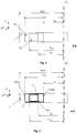
- Fig. 1 represents a perspective view of a bumper system (4) comprising a cross beam (1), two absorbers (2, 2') and two intermediate components (3, 3').
- the cross beam is curved and extending in a transverse direction (Y). It is constituted of an extrusion member with a length W and having a rear wall (5) and a front wall (6).
- the rear wall (5) is located in the inwardly edge of the curved cross beam.
- the front wall (6) is located in the outwardly edge of the curved cross beam.
- the rear wall is opposed and spaced from the front wall.
- the two absorbers (2, 2') are positioned on the inwardly edge of the curved cross beam and are substantially positioned symmetrically to the longitudinal axis (LL).
- the longitudinal axis (LL) is passing at mid width W/2 of the cross beam. It may correspond with the symmetrical axis of a motor vehicle (not represented) on which the bumper system can be installed. This longitudinal axis is parallel with a longitudinal direction (X), said longitudinal direction (X) can also correspond to the driving direction of the vehicle (not represented).
- an intermediate component (3, 3') is positioned in between the cross beam (1) and an absorber (2, 2') in between the cross beam (1) and an absorber (2, 2') an intermediate component (3, 3') is positioned.
- the intermediate component (3, 3') is connected to the rear wall (5) of the cross beam (1) through a first contact area (10, 10').
- the first contact area corresponds to the whole surface of the intermediate component lying on the rear wall (5).
- the first contact area can correspond to only a part of the surface of the intermediate component lying on the rear wall and maybe formed by several non-contiguous surfaces.
- the intermediate component (3, 3') is also connected to the absorber (2, 2') through a second contact area (20, 20').
- Fig. 2 is a cross-section of the left assembly cross beam/intermediate component/absorber represented at Fig.1 .
- the first contact area is distant from the longitudinal axis (LL), by an internal component distance, called L in , and an external component distance, called L out , which corresponds respectively to the minimum and maximum distance between said first contact area and the longitudinal axis (LL).
- the absorber (2) comprises a profile member (7) which extend parallel to the longitudinal direction (X).
- the profile member is attached at one end to an endplate (9) which permits to attach the absorber to longitudinal beam of the vehicle (not represented) and at the other end to the intermediate component, through a second contact area (20).
- the second contact area in the case represented at Fig. 2 corresponds to the whole section of the profile member (7).
- the second contact area is distant from the longitudinal axis (LL) by an internal profile distance, called D in , and an external profile distance, called D out , which corresponds respectively to the minimum and maximum distance between the second contact area and the longitudinal axis (LL).
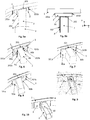
- Fig. 3 is a cross section B-B of Fig. 2 showing the first contact area (10) and the second contact area (20).
- Fig. 4 corresponds to a similar embodiment of Fig. 3 but shows the location of the connections, where in the represented case corresponds to seam weld lines.
- the connections could be performed by bonding or a mix of bonding and welding.
- the intermediate component is attached to the cross beam via seam weld line (101a, 101b) which is non continuous, i.e. the seam weld lineis composed of two separate seam weld lines (101a, 101b) located on the two extremities of the first contact area; seam weld line 101a is positioned in an area distant of L out from the longitudinal axis LL and line 101b is distant from L in from the longitudinal axis LL.
- the two separate seam weld lines can be located in an area distant from the longitudinal axis by a distance comprised between 0.8 Lout and Lout or between L in and 1.2 L in .
- the intermediate component is attached to the absorber via a seam weld line (201); it is peripheral and partly or fully encircled the second contact area (20).
- Fig. 5a and Fig. 5b represents a particular embodiment of the invention where the intermediate component has a flange (30), connected to the outer wall (8) of the absorber (2).
- the intermediate component is attached to the absorber via a seam weld line (201, 202) which is non continuous.
- the seam weldline is composed of two separate seam weld line (201 and 202) wherein one of these seam weld lines (202) correspond to the connection between the flange and the outer wall (8).
- Fig. 6 differs from Fig. 5 by the presence of two flanges (30a, 30b) in the intermediate component (3).
- each flange (30a, 30b) is connected to an outer wall of the absorber (8a, 8b).
- Each flange is attached via a seam weld line (202a, 202b).
- Fig. 7 represents a particular embodiment of the invention where the intermediate component comprises reinforcing parts (40a, 40b).
- Fig. 8 represents a particular embodiment of the invention where the intermediate component comprises attachment means (50a, 50b).
- the attachment means may permit to attach further components, like horns, electronic devices, reinforcement parts, lashing points or spot light.
- Fig. 9 and Fig. 10 represent the case where the intermediate component (3) is outfitted with a through opening for the passage of a towing device.
- Fig. 9 corresponds to the case where the thread for the towing hook (60) is attached separately to the intermediate component.
- the thread is in this case is included into an extra part which is attached to the intermediate component, for instance by welding or bonding.
- Fig. 10 corresponds to the case where the thread is integrated into the intermediate component.
- the intermediate component and the thread is monolithic, i.e. without the need of any external attachments. Preferably, it is obtained by extrusion.
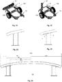
- a RCAR bumper barrier test and a pole barrier test on a bumper system have been executed on two types of bumper system: a first bumper system, represented at Fig 13 corresponding to prior art, i.e. without an intermediate component and a second bumper system represented at Fig. 14 corresponding to the invention.
- a first bumper system represented at Fig 13 corresponding to prior art, i.e. without an intermediate component
- a second bumper system represented at Fig. 14 corresponding to the invention.
- the same geometry of cross beam with three chambers represented on Fig. 16
- the same absorbers, represented on Fig. 17 has been used and are positioned symmetrically around the longitudinal axis LL at a distance of 430 mm (see Fig. 15 ).
- the bumper system for both configurations is made in aluminium alloy, having a young modulus of 70 GPa.
- the absorbers are welded directly to the cross beam.
- an intermediate component with a flange made in aluminium alloy with a young modulus of 70 GPa and represented on Fig. 14 is placed between the cross beam and the absorber and is attached by welding to the cross beam through a first contact area and to the absorber through a second contact area.
- Table 1 shows the distance between the longitudinal axis LL and the first and second contact areas (also represented on Fig. 15 ).
- the corresponding area moment of inertia about the vertical Z axis of the part of the cross beam distant from the longitudinal axis (LL) by a distance comprised between L out and D in and the area moment of inertia about the vertical Z axis of the intermediate component distant between L out and D out are also included in Table 1.
- the corresponding bending stiffness is then deduced by multiplying the area moment of inertia by the young modulus of the material constituting the two elements (here aluminum).
- the bumper system (4) is fixed on the body-in-white longitudinals (13a, 13b), and said longitudinals are fixed on a bob-sled (16) as represented at Fig. 11 and Fig. 12 .
- the RCAR bumper barrier test is conducted at 10.5 km/h and the pole barrier test at a speed ranging between 15 and 64 km/h.
- the energy absorption capacity of the bumper system during a crash is evaluated by the load displacement response.
- the area under the load-displacement curve is a measure of the energy absorbed.
- the bumper system has the function of preventing damage to the body in white.
- the maximal displacement is specified by the vehicle design. Indeed, it is needed that no damage of the cooling system, nor of security-relevant components occur during the crash.
- the ideal bumper system has a load-displacement response which acts as a step function; the load rapidly reaches the maximum value and remains there throughout the crash. For a given maximum displacement, higher load, better bumper system.
- the load-force versus the displacement for the two configurations with and without the intermediate components and for the two conditions of tests are represented on Fig. 18 and 19 .
- the dashed lines correspond to the bumper system according to prior art (curve B), without an intermediate component and the bold lines to the bumper system according to the invention (curve A). In both cases, the curves correspond to simulated curves by FEM modelling.
- the force sustained by the bumper system according to the invention is smaller than the corresponding force of the prior art due to the lower stiffness of the assembly, but it has no effect of the total energy absorption of the bumper system, which remain higher than the bumper system according to the prior art.
Landscapes
- Engineering & Computer Science (AREA)
- Mechanical Engineering (AREA)
- Transportation (AREA)
- Body Structure For Vehicles (AREA)
- Vibration Dampers (AREA)
Priority Applications (6)
| Application Number | Priority Date | Filing Date | Title |
|---|---|---|---|
| EP18195823.2A EP3626545A1 (en) | 2018-09-20 | 2018-09-20 | Enhanced bumper system |
| PCT/EP2019/075348 WO2020058485A1 (en) | 2018-09-20 | 2019-09-20 | Enhanced bumper system |
| CN201980057558.4A CN112638724B (zh) | 2018-09-20 | 2019-09-20 | 加强的保险杠系统 |
| US17/263,981 US11485304B2 (en) | 2018-09-20 | 2019-09-20 | Enhanced bumper system |
| EP19772729.0A EP3853076A1 (en) | 2018-09-20 | 2019-09-20 | Enhanced bumper system |
| KR1020217011425A KR20210059760A (ko) | 2018-09-20 | 2019-09-20 | 향상된 범퍼 시스템 |
Applications Claiming Priority (1)
| Application Number | Priority Date | Filing Date | Title |
|---|---|---|---|
| EP18195823.2A EP3626545A1 (en) | 2018-09-20 | 2018-09-20 | Enhanced bumper system |
Publications (1)
| Publication Number | Publication Date |
|---|---|
| EP3626545A1 true EP3626545A1 (en) | 2020-03-25 |
Family
ID=63667838
Family Applications (2)
| Application Number | Title | Priority Date | Filing Date |
|---|---|---|---|
| EP18195823.2A Withdrawn EP3626545A1 (en) | 2018-09-20 | 2018-09-20 | Enhanced bumper system |
| EP19772729.0A Pending EP3853076A1 (en) | 2018-09-20 | 2019-09-20 | Enhanced bumper system |
Family Applications After (1)
| Application Number | Title | Priority Date | Filing Date |
|---|---|---|---|
| EP19772729.0A Pending EP3853076A1 (en) | 2018-09-20 | 2019-09-20 | Enhanced bumper system |
Country Status (5)
| Country | Link |
|---|---|
| US (1) | US11485304B2 (zh) |
| EP (2) | EP3626545A1 (zh) |
| KR (1) | KR20210059760A (zh) |
| CN (1) | CN112638724B (zh) |
| WO (1) | WO2020058485A1 (zh) |
Cited By (2)
| Publication number | Priority date | Publication date | Assignee | Title |
|---|---|---|---|---|
| EP3936391A1 (en) | 2020-07-10 | 2022-01-12 | Constellium Singen GmbH | Crash management system with an additional element connecting the absorber to the cross beam |
| WO2022058305A1 (en) * | 2020-09-15 | 2022-03-24 | Atlas Technologies Holding B.V. | Bumper system for an automotive vehicle |
Families Citing this family (3)
| Publication number | Priority date | Publication date | Assignee | Title |
|---|---|---|---|---|
| US11590911B2 (en) | 2019-07-26 | 2023-02-28 | Shape Corp. | Hybrid bumper assembly for a vehicle |
| CN115605539A (zh) | 2021-05-10 | 2023-01-13 | 株式会社Lg化学(Kr) | 用于汽车内饰材料的复合树脂组合物和使用该复合树脂组合物制造的汽车内饰材料 |
| EP4339035A1 (en) * | 2022-09-16 | 2024-03-20 | Constellium Singen GmbH | Crash management system for a front or rear area of a motor vehicle |
Citations (16)
| Publication number | Priority date | Publication date | Assignee | Title |
|---|---|---|---|---|
| DE102006019567B3 (de) * | 2006-04-27 | 2007-11-08 | Daimlerchrysler Ag | Verfahren zum Herstellen umgeformter Stahlbauteile |
| US20090079210A1 (en) * | 2007-09-21 | 2009-03-26 | Katsuya Matsumura | Bumper attachment portion structure |
| US7837244B2 (en) | 2009-02-12 | 2010-11-23 | Kobe Steel, Ltd. | Automobile body reinforcement with excellent bending crush characteristics |
| DE102009048466A1 (de) * | 2009-10-07 | 2011-04-14 | Audi Ag | Trägerverbund für ein Kraftfahrzeug und Kraftfahrzeug |
| EP2335984A2 (de) | 2009-12-02 | 2011-06-22 | Benteler Automobiltechnik GmbH | Crashbox und Verfahren zu deren Herstellung |
| WO2011075031A1 (en) | 2009-12-17 | 2011-06-23 | Gestamp Hardtech Ab | Bumper for a vehicle |
| DE102011121381A1 (de) | 2011-12-19 | 2013-06-20 | Waldaschaff Automotive GmbH | Verfahren zur Herstellung eines Aufprallquerträgers sowie Aufprallquerträger |
| US8590952B2 (en) | 2010-12-06 | 2013-11-26 | Hyundai Motor Company | Crash box of bumper for vehicle |
| EP2668068A1 (en) | 2011-01-24 | 2013-12-04 | Constellium Singen GmbH | Tubular beam of an automotive structure having an improved impact behavior |
| WO2014030592A1 (ja) | 2012-08-21 | 2014-02-27 | 新日鐵住金株式会社 | クラッシュボックス及び自動車車体 |
| US8844987B2 (en) | 2012-03-14 | 2014-09-30 | Aisin Seiki Kabushiki Kaisha | Crash box and bumper device |
| US8919834B2 (en) | 2011-06-29 | 2014-12-30 | Magna International Inc. | Bumper assembly and method |
| US20160144814A1 (en) * | 2014-11-20 | 2016-05-26 | Hyundai Motor Company | Crash box of vehicle having integrated joint structure by spot welding and assembly method thereof |
| US20160264084A1 (en) | 2015-03-13 | 2016-09-15 | Benteler Automobiltechnik Gmbh | Bumper system for a motor vehicle |
| US20160297387A1 (en) | 2015-04-13 | 2016-10-13 | Benteler Automobiltechnik Gmbh | Bumper arrangement for a motor vehicle |
| US9725057B2 (en) | 2014-06-03 | 2017-08-08 | Hyundai Motor Company | Crash box for vehicle |
Family Cites Families (23)
| Publication number | Priority date | Publication date | Assignee | Title |
|---|---|---|---|---|
| JPS5115250Y2 (zh) * | 1971-11-16 | 1976-04-22 | ||
| US4465312A (en) * | 1982-10-04 | 1984-08-14 | Chrysler Corporation | Tuned bumper mounting system |
| JPS62128852A (ja) * | 1985-11-29 | 1987-06-11 | Honda Motor Co Ltd | 自動車用合成樹脂製バンパ |
| JP2772621B2 (ja) * | 1994-09-30 | 1998-07-02 | 本田技研工業株式会社 | バンパビーム |
| US5984390A (en) * | 1997-10-06 | 1999-11-16 | Chrysler Corporation | Front bumper energy absorption and management system |
| EP1533192A1 (de) * | 2003-11-19 | 2005-05-25 | Alcan Technology & Management Ltd. | Stossfängersystem |
| JP2006142876A (ja) * | 2004-11-16 | 2006-06-08 | Denso Corp | 衝突対象物判別装置および衝突対象物判別方法 |
| DE102004060088B3 (de) * | 2004-12-13 | 2006-02-16 | Benteler Automobiltechnik Gmbh | Stoßfängeranordnung für ein Kraftfahrzeug |
| US7808621B2 (en) | 2005-07-29 | 2010-10-05 | Verizon New England Inc. | System and method for identifying fiber optic cables |
| CN101528509A (zh) * | 2006-10-24 | 2009-09-09 | 沙普公司 | 表面中带有整体形成肋的b型梁 |
| JP4375451B2 (ja) * | 2007-07-13 | 2009-12-02 | 株式会社デンソー | 車両用衝突検知装置 |
| US7959197B2 (en) * | 2008-10-30 | 2011-06-14 | Shape Corp. | Bumper beam with multi-concavity-defining cross section |
| JP2010179832A (ja) * | 2009-02-06 | 2010-08-19 | Aisin Seiki Co Ltd | 車両用バンパ装置 |
| JP2011051364A (ja) * | 2009-08-31 | 2011-03-17 | Nikkeikin Aluminium Core Technology Co Ltd | バンパー構造 |
| JP5564237B2 (ja) * | 2009-11-27 | 2014-07-30 | 株式会社アステア | バンパ補強材 |
| DE102010050013B4 (de) * | 2010-11-02 | 2020-07-09 | Benteler Automobiltechnik Gmbh | Stoßfängeranordnung für ein Kraftfahrzeug |
| JP5864217B2 (ja) * | 2011-11-04 | 2016-02-17 | アイシン精機株式会社 | バンパ補強材 |
| DE102012022899A1 (de) * | 2012-11-23 | 2014-05-28 | Volkswagen Aktiengesellschaft | Verbindungselement zur Abstützung eines Stoßfängers eines Kraftfahrzeuges gegenüber einem Montageträger, Baueinheit mit einem solchen Verbindungselement sowie Verfahren zur Herstellung eines Verbindungselements |
| JP2015104972A (ja) * | 2013-11-29 | 2015-06-08 | アイシン精機株式会社 | 衝撃吸収部材 |
| DE102014009941A1 (de) * | 2014-07-04 | 2016-01-07 | GM Global Technology Operations LLC (n. d. Ges. d. Staates Delaware) | Stoßfängeraufbau für ein Kraftfahrzeug |
| EP3009306A1 (en) * | 2014-10-15 | 2016-04-20 | Constellium Singen GmbH | Attachment means for mounting a bumper cross-beam onto a vehicle structure enabling additional function assembly |
| DE102015004420A1 (de) * | 2015-04-02 | 2016-10-06 | GM Global Technology Operations LLC (n. d. Ges. d. Staates Delaware) | Frontpartie für ein Kraftfahrzeug |
| SE1751561A1 (en) * | 2017-12-18 | 2019-06-19 | Gestamp Hardtech Ab | Crash box for a bumper |
-
2018
- 2018-09-20 EP EP18195823.2A patent/EP3626545A1/en not_active Withdrawn
-
2019
- 2019-09-20 CN CN201980057558.4A patent/CN112638724B/zh active Active
- 2019-09-20 EP EP19772729.0A patent/EP3853076A1/en active Pending
- 2019-09-20 WO PCT/EP2019/075348 patent/WO2020058485A1/en unknown
- 2019-09-20 US US17/263,981 patent/US11485304B2/en active Active
- 2019-09-20 KR KR1020217011425A patent/KR20210059760A/ko unknown
Patent Citations (16)
| Publication number | Priority date | Publication date | Assignee | Title |
|---|---|---|---|---|
| DE102006019567B3 (de) * | 2006-04-27 | 2007-11-08 | Daimlerchrysler Ag | Verfahren zum Herstellen umgeformter Stahlbauteile |
| US20090079210A1 (en) * | 2007-09-21 | 2009-03-26 | Katsuya Matsumura | Bumper attachment portion structure |
| US7837244B2 (en) | 2009-02-12 | 2010-11-23 | Kobe Steel, Ltd. | Automobile body reinforcement with excellent bending crush characteristics |
| DE102009048466A1 (de) * | 2009-10-07 | 2011-04-14 | Audi Ag | Trägerverbund für ein Kraftfahrzeug und Kraftfahrzeug |
| EP2335984A2 (de) | 2009-12-02 | 2011-06-22 | Benteler Automobiltechnik GmbH | Crashbox und Verfahren zu deren Herstellung |
| WO2011075031A1 (en) | 2009-12-17 | 2011-06-23 | Gestamp Hardtech Ab | Bumper for a vehicle |
| US8590952B2 (en) | 2010-12-06 | 2013-11-26 | Hyundai Motor Company | Crash box of bumper for vehicle |
| EP2668068A1 (en) | 2011-01-24 | 2013-12-04 | Constellium Singen GmbH | Tubular beam of an automotive structure having an improved impact behavior |
| US8919834B2 (en) | 2011-06-29 | 2014-12-30 | Magna International Inc. | Bumper assembly and method |
| DE102011121381A1 (de) | 2011-12-19 | 2013-06-20 | Waldaschaff Automotive GmbH | Verfahren zur Herstellung eines Aufprallquerträgers sowie Aufprallquerträger |
| US8844987B2 (en) | 2012-03-14 | 2014-09-30 | Aisin Seiki Kabushiki Kaisha | Crash box and bumper device |
| WO2014030592A1 (ja) | 2012-08-21 | 2014-02-27 | 新日鐵住金株式会社 | クラッシュボックス及び自動車車体 |
| US9725057B2 (en) | 2014-06-03 | 2017-08-08 | Hyundai Motor Company | Crash box for vehicle |
| US20160144814A1 (en) * | 2014-11-20 | 2016-05-26 | Hyundai Motor Company | Crash box of vehicle having integrated joint structure by spot welding and assembly method thereof |
| US20160264084A1 (en) | 2015-03-13 | 2016-09-15 | Benteler Automobiltechnik Gmbh | Bumper system for a motor vehicle |
| US20160297387A1 (en) | 2015-04-13 | 2016-10-13 | Benteler Automobiltechnik Gmbh | Bumper arrangement for a motor vehicle |
Cited By (4)
| Publication number | Priority date | Publication date | Assignee | Title |
|---|---|---|---|---|
| EP3936391A1 (en) | 2020-07-10 | 2022-01-12 | Constellium Singen GmbH | Crash management system with an additional element connecting the absorber to the cross beam |
| WO2022008682A1 (en) | 2020-07-10 | 2022-01-13 | Constellium Singen Gmbh | Crash management system with an additional element connecting the absorber to the cross beam |
| WO2022058305A1 (en) * | 2020-09-15 | 2022-03-24 | Atlas Technologies Holding B.V. | Bumper system for an automotive vehicle |
| NL2026470B1 (en) * | 2020-09-15 | 2022-05-16 | Atlas Technologies Holding Bv | Bumper system for an automotive vehicle |
Also Published As
| Publication number | Publication date |
|---|---|
| US20210316684A1 (en) | 2021-10-14 |
| CN112638724A (zh) | 2021-04-09 |
| WO2020058485A1 (en) | 2020-03-26 |
| EP3853076A1 (en) | 2021-07-28 |
| KR20210059760A (ko) | 2021-05-25 |
| US11485304B2 (en) | 2022-11-01 |
| CN112638724B (zh) | 2023-11-14 |
Similar Documents
| Publication | Publication Date | Title |
|---|---|---|
| EP3626545A1 (en) | Enhanced bumper system | |
| EP1373025B1 (en) | Arrangement for underrun protection in vehicles | |
| US7063376B2 (en) | Structural member for a vehicle frame assembly | |
| US9969431B2 (en) | Double angled rail system for a vehicle | |
| US20230047814A1 (en) | Connecting element for improved crash behaviour in a car to car collision | |
| US11220296B2 (en) | Vehicle structural member for improved lateral loading | |
| CN114375266B (zh) | 具有溃压箱支架的车辆保险杠扩展件 | |
| US11713011B2 (en) | Bumper assembly with reinforced impact dispersion plates | |
| JP3120736B2 (ja) | キャブオーバ型車両の安全装置 | |
| US11814100B2 (en) | Vehicle cradle assembly with impact detachment script | |
| CN111565998B (zh) | 轿车车身结构和车身 | |
| EP4316919A1 (en) | Side extension for crash management system | |
| JP2012030624A (ja) | 自動車用バンパー | |
| JP2003072590A (ja) | フロントアンダーランプロテクタ | |
| EP4015314A1 (en) | Crash extension for crash management system | |
| EP4187121A1 (en) | Deformation element in an impact absorbing structure | |
| US20240149816A1 (en) | Vehicle reinforcement beam | |
| CN219857063U (zh) | 防撞结构和配备有该防撞结构的车辆 | |
| US20240217584A1 (en) | Vehicle frame assembly having an energy absorbing device | |
| US20240227711A9 (en) | Bumper assembly with a connecting device between a deformation element and a cross member, and motor vehicle | |
| KR101640025B1 (ko) | 차량용 범퍼 빔 유닛 | |
| JP2602848Y2 (ja) | 自動車のガードバー取付構造 | |
| KR19980047978A (ko) | 차량의 오프셋 충돌 보강구조 | |
| JPH0867218A (ja) | バンパーリインフォースメント | |
| JPH08169286A (ja) | 衝突対策用衝撃吸収部材の取付構造 |
Legal Events
| Date | Code | Title | Description |
|---|---|---|---|
| PUAI | Public reference made under article 153(3) epc to a published international application that has entered the european phase |
Free format text: ORIGINAL CODE: 0009012 |
|
| STAA | Information on the status of an ep patent application or granted ep patent |
Free format text: STATUS: THE APPLICATION HAS BEEN PUBLISHED |
|
| AK | Designated contracting states |
Kind code of ref document: A1 Designated state(s): AL AT BE BG CH CY CZ DE DK EE ES FI FR GB GR HR HU IE IS IT LI LT LU LV MC MK MT NL NO PL PT RO RS SE SI SK SM TR |
|
| AX | Request for extension of the european patent |
Extension state: BA ME |
|
| STAA | Information on the status of an ep patent application or granted ep patent |
Free format text: STATUS: THE APPLICATION IS DEEMED TO BE WITHDRAWN |
|
| 18D | Application deemed to be withdrawn |
Effective date: 20200926 |