EP3009306A1 - Attachment means for mounting a bumper cross-beam onto a vehicle structure enabling additional function assembly - Google Patents
Attachment means for mounting a bumper cross-beam onto a vehicle structure enabling additional function assembly Download PDFInfo
- Publication number
- EP3009306A1 EP3009306A1 EP14003527.0A EP14003527A EP3009306A1 EP 3009306 A1 EP3009306 A1 EP 3009306A1 EP 14003527 A EP14003527 A EP 14003527A EP 3009306 A1 EP3009306 A1 EP 3009306A1
- Authority
- EP
- European Patent Office
- Prior art keywords
- wall
- attachment means
- flange
- cross
- bumper
- Prior art date
- Legal status (The legal status is an assumption and is not a legal conclusion. Google has not performed a legal analysis and makes no representation as to the accuracy of the status listed.)
- Withdrawn
Links
Images


Classifications
-
- B—PERFORMING OPERATIONS; TRANSPORTING
- B60—VEHICLES IN GENERAL
- B60R—VEHICLES, VEHICLE FITTINGS, OR VEHICLE PARTS, NOT OTHERWISE PROVIDED FOR
- B60R19/00—Wheel guards; Radiator guards, e.g. grilles; Obstruction removers; Fittings damping bouncing force in collisions
- B60R19/02—Bumpers, i.e. impact receiving or absorbing members for protecting vehicles or fending off blows from other vehicles or objects
- B60R19/24—Arrangements for mounting bumpers on vehicles
-
- B—PERFORMING OPERATIONS; TRANSPORTING
- B60—VEHICLES IN GENERAL
- B60R—VEHICLES, VEHICLE FITTINGS, OR VEHICLE PARTS, NOT OTHERWISE PROVIDED FOR
- B60R19/00—Wheel guards; Radiator guards, e.g. grilles; Obstruction removers; Fittings damping bouncing force in collisions
- B60R19/02—Bumpers, i.e. impact receiving or absorbing members for protecting vehicles or fending off blows from other vehicles or objects
- B60R19/48—Bumpers, i.e. impact receiving or absorbing members for protecting vehicles or fending off blows from other vehicles or objects combined with, or convertible into, other devices or objects, e.g. bumpers combined with road brushes, bumpers convertible into beds
Definitions
- the invention relates to attachment means for mounting a bumper cross-beam onto a vehicle structure.
- the invention relates more particularly to the design of the end of the said attachment means, which is to be fixed to the bumper cross-beam.
- Such attachment means are advantageously deformation elements, also called “Crash-Box” or “C-Box”, which are designed to absorb by plastic deformation as most as possible kinetic energy in case of crash of the vehicle.
- a bumper cross-beam comprises generally vertical front and rear walls, which play respectively the role of compressive strut and tensile strut in case of collision and which are spaced apart thanks to transverse or flanking walls. These flanking walls are usually horizontal upper and lower walls.
- Bumper cross-beams are often profiles advantageously extruded from an aluminium alloy, comprising a hollow section member with at least a chamber delimited by the said vertical front and rear walls and horizontal upper and lower flanking walls. Bumper cross-beams are designed such that the force at which they begin to plastically deform is lower than the force necessary to irreversibly deform the vehicle structure. In the case of a minor collision, only the bumper cross-beam is deformed with the result that this sole part has to be replaced.
- deformation elements also called “crash-boxes”
- crash-boxes have been proposed to increase the maximum force of impact at which there is still no plastic deformation of the vehicle structure.
- the cross-beam and the vehicle structure e.g. its longitudinal beams
- they are further used as attachment means. They are designed to be plastically deformed as soon as the kinetic energy of the vehicle at the time of the collision is higher than a critical value.
- Their plastic deformation is advantageously a progressive folding, which absorbs at least partially the energy of impact.
- the deformation elements are usually in the form of hollow section profiles, generally multi-chamber hollow section profiles, whereby their longitudinal axis lies in the direction of the longitudinal axis of the vehicle.
- the patent US 7,401,825 describes a bumper with an attachment member to be made thereon for the purpose of mounting the bumper onto longitudinal beams of a vehicle, such that section walls acting as compressive and tensile struts and a pair of flanking walls joining them form a hollow section.
- the attachment member is in the form of a hollow section exhibiting at least one side wall and two transverse walls following on therefrom with a length of hollow section with the longitudinal beam.
- the hollow section is in the form of a push-fit length matching the inner cross-section of the longitudinal beam.
- the other end region of the attachment member is provided with collar-type parts projecting from their end edges and aligned approximately parallel to the transverse walls.
- German patent application DE 10 2008 022 564 describes a cross beam fastened to body components of a motor vehicle body by supporting elements i.e. absorber element.
- the cross beam is fastenable to the supporting elements at two retaining positions and/or the supporting elements are fastened to the body components of the body in the retaining positions.
- the supporting elements comprise a respective retainer for the cross beam, where the retainer is formed by upper and lower bars.
- the supporting elements are formed from extruded sections or from metal sheets.
- a first object of the invention is an attachment means for mounting a bumper cross-beam having a vertical front wall and a vertical rear wall spaced apart by at least one transverse wall onto a vehicle structure, the said attachment means having a first end to be fixed to the said vehicle structure and a second end designed to be attached to the said bumper cross-beam, the said attachment means being made from a hollow section profile, the periphery of which comprises opposite side walls and substantially parallel opposite outer walls characterised in that the said second end comprises at least one flange, which can extend substantially beyond said vertical front wall after mounting the bumper cross beam.
- the attachment means is designed for mounting the said bumper cross-beam onto a vehicle structure, typically, on its longitudinal beams.
- the said hollow section profile is a section profile extruded from an aluminium alloy, typically an alloy belonging to the 6xxx Aluminium Association series.
- the said attachments means are deformation elements, also called “Crash Box” or “C-Box” designed to absorb at least partially the energy of impact by buckling-free progressive plastic folding thereof.
- said hollow section profile is a multi-chamber hollow section profile comprising at least a peripheral chamber, being at least delimited by one of the said outer walls and an inner wall which is substantially parallel to the said outer wall and extends between the opposite side walls.
- said hollow section profile is a multi-chamber hollow section profile comprising two opposite peripheral chamber.
- said flange is a double walled flange which results from bringing closer together the outer wall and the inner wall of the peripheral chamber until they are in contact, such that the said peripheral chamber collapses.
- the collapse may be realized by pushing the inner wall towards the outer wall or alternatively by pushing the outer wall towards the inner wall.
- an upper flange and a lower flange there is provided an upper flange and a lower flange, the upper flange can be obtained by collapsing an upper chamber of the hollow section profile and the lower flange can be obtained by collapsing a lower chamber of the hollow section profile. It is possible to adapt the distance between the upper and lower flange by pushing the inner wall towards the outer wall, which provides a greater distance or alternatively by pushing the outer wall towards the inner wall which provides a smaller distance, with any appropriate combination.
- the multi-chamber hollow section profiles comprise an upper chamber and a lower chamber separated by a middle chamber.
- the walls other than the said opposite outer wall and inner wall, which complete the delimitation of the said peripheral chamber are parts of the said opposite side walls. Since the multi-chamber hollow section profile may comprise more than three chambers, e.g. additional lateral chambers, the walls other than the said opposite outer wall and inner wall, which complete the delimitation of the said peripheral chamber may be walls, which separate the said peripheral chamber from the said lateral chambers.
- the flange which can extend substantially beyond said vertical front wall of the bumper cross beam after mounting said bumper cross beam enables to attach a component in front of the vertical front wall of the cross beam.
- the length of the portion of the flange extending beyond the vertical front wall of the cross-beam is a least one tenth and preferably one fifth of the distance between the opposite side walls of the attachment means, a typical length is between 5 and 80 mm and preferably between 10 and 60 mm.
- the portion of the flange which extends beyond the vertical front wall of the cross beam may have the same width as the outer walls of the hollow section profiles. It can also advantageously be cut to a narrower width adapted to the size of the added component. Typically the width of the portion of the flange which extends beyond the vertical front wall of the cross-beam is between three fifth and one fifth of the distance between the opposite side walls of the attachment means, with a typical minimum width of 5 mm. In another embodiment the width of the portion of the flange which extends beyond the vertical front wall of the cross-beam is greater than the distance between the opposite side walls of the attachment means, which is be obtained when the flange is processed by chip-less forming and the folded side walls of the attachment means are made part of the flange.
- a reinforcement part is added on the flange, for example to facilitate bolting of the added component.
- the reinforcement part may advantageously have the shape of the portion of the flange which extends beyond the vertical front wall of the cross beam.
- the attachment means is made of a multi chamber hollow section having peripheral chambers with an outer wall and an inner wall, the outer wall may be cut out and the reinforcement attached to the inner wall.
- the bumper cross-beam is also a hollow section profile made of an extruded section from an aluminium alloy, typically an alloy belonging to the 6xxx Aluminium Association series.
- Another object of the invention is a bumper system comprising a bumper cross beam and at least an attachment means according to the invention.
- the bumper system advantageously comprises a component attached to the flange in front of the vertical front wall.
- the component may be for example an energy-absorbing element, a pendulum-stopper, an additional energy-absorbing-element for Pedestrian -impact, a radar-sensor; an acceleration-sensor, a horn, a module-carrier, a support for fascia.
- the invention is advantageous because the cross beam is not weakened by the addition of the component.
- the energy absorption potential may even be improved if the added component has energy-absorbing properties.
- Yet another object of the invention is a process for manufacturing a bumper system comprising an attachment means, a bumper cross-beam and a component, the said process comprising following successive steps :
- methods such as cutting out the opposite side walls and optionally one outer wall, collapsing a peripheral chambers after optionally cutting out side walls, cutting out inner walls may be appropriate.
- the bumper system (100) comprises a bumper cross-beam (10) and two attachment means (20) for mounting the said bumper cross-beam onto the longitudinal beams of a vehicle (not illustrated).
- the bumper cross-beam comprises a front wall (11) and a rear wall (12) spaced apart thanks to flanking walls.
- Each attachment means is made from a hollow section profile (21) having a first end (22) to be fixed to the said longitudinal beams of the vehicle structure and a second end (23) designed to attach the said bumper cross-beam (10).
- a flange (41) extends substantially beyond said vertical front wall (11) of the bumper cross beam (10) which can be used to fix a component in front of the front wall.
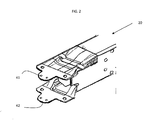
- FIG. 2 there is provided a detailed perspective view of an embodiment of the second end of an attachment means (20) according to the invention, showing flanges (41) and (42) which can be used to fix a component.
- Fig 4 is a cross section of the assembly according to the dotted line (A:A') shown on Figure 3 .
- the attachment means (20) which is, in the illustrated embodiment a crash-box, is fixed to a cross-beam (10) made of a hollow profile having a vertical front wall (11) and a vertical rear wall (12) spaced apart by at least one transverse wall (13).
- the said attachment means has a first end (22) designed to be fixed to the vehicle structure and a second end (23) designed to be attached to the said bumper cross-beam.
- the said attachment means is made from a hollow section profile (21), the periphery of which comprises opposite side walls (24 and 25) and substantially parallel opposite outer walls (26 and 27).
- the hollow section profile (21) comprises three chambers, the lower chamber (30) is at least delimited by the lower outer wall (27) and a lower inner wall (32), which is substantially parallel to the lower outer wall and extends between the opposite side walls (24 and 25).
- the upper chamber (29) is at least delimited by the upper outer wall (26) and an upper inner wall (31), which is substantially parallel to the said upper outer wall and extends between the opposite side walls (24 and 25).
- the said second end (23) comprises two flanges (41, 42), which extend substantially beyond said vertical front wall (11) of the bumper cross beam (10).
- said flanges (41, 42) are double-walled flanges which result from bringing closer together the outer wall and the inner wall of the peripheral chambers (29, 30) until they are in contact, such that the peripheral chamber collapses.
- an upper flange obtained by pushing the upper outer wall (21) towards the upper inner wall (31) and a lower flange obtained by pushing the lower inner (32) wall towards the lower outer wall (27).
- the length of the flanges is adapted to extend substantially beyond said vertical front wall (11) of the cross-beam (10).
- FIG. 5 Illustrated by Figure 5 is a local view of a bumper assembly according to the invention wherein a component (50) has been attached to the flange (41).
- FIG. 6 there is provided a cross-section view of second end of a bumper system according to the invention wherein reinforcement parts (48,49) are added on the flange, for example to facilitate bolting of the added component and wherein a part of the outer walls (26, 27) has been cut out to facilitate the addition of the reinforcement part.
Landscapes
- Engineering & Computer Science (AREA)
- Mechanical Engineering (AREA)
- Body Structure For Vehicles (AREA)
- Vibration Dampers (AREA)
Abstract
Description
- The invention relates to attachment means for mounting a bumper cross-beam onto a vehicle structure. The invention relates more particularly to the design of the end of the said attachment means, which is to be fixed to the bumper cross-beam. Such attachment means are advantageously deformation elements, also called "Crash-Box" or "C-Box", which are designed to absorb by plastic deformation as most as possible kinetic energy in case of crash of the vehicle.
- A bumper cross-beam comprises generally vertical front and rear walls, which play respectively the role of compressive strut and tensile strut in case of collision and which are spaced apart thanks to transverse or flanking walls. These flanking walls are usually horizontal upper and lower walls. Bumper cross-beams are often profiles advantageously extruded from an aluminium alloy, comprising a hollow section member with at least a chamber delimited by the said vertical front and rear walls and horizontal upper and lower flanking walls. Bumper cross-beams are designed such that the force at which they begin to plastically deform is lower than the force necessary to irreversibly deform the vehicle structure. In the case of a minor collision, only the bumper cross-beam is deformed with the result that this sole part has to be replaced. In the past, deformation elements, also called "crash-boxes", have been proposed to increase the maximum force of impact at which there is still no plastic deformation of the vehicle structure. Located between the cross-beam and the vehicle structure (e.g. its longitudinal beams), they are further used as attachment means. They are designed to be plastically deformed as soon as the kinetic energy of the vehicle at the time of the collision is higher than a critical value. Their plastic deformation is advantageously a progressive folding, which absorbs at least partially the energy of impact. The deformation elements are usually in the form of hollow section profiles, generally multi-chamber hollow section profiles, whereby their longitudinal axis lies in the direction of the longitudinal axis of the vehicle.
- The patent
US 7,401,825 describes a bumper with an attachment member to be made thereon for the purpose of mounting the bumper onto longitudinal beams of a vehicle, such that section walls acting as compressive and tensile struts and a pair of flanking walls joining them form a hollow section. The attachment member is in the form of a hollow section exhibiting at least one side wall and two transverse walls following on therefrom with a length of hollow section with the longitudinal beam. The hollow section is in the form of a push-fit length matching the inner cross-section of the longitudinal beam. The other end region of the attachment member is provided with collar-type parts projecting from their end edges and aligned approximately parallel to the transverse walls. - German
patent application DE 10 2008 022 564 describes a cross beam fastened to body components of a motor vehicle body by supporting elements i.e. absorber element. The cross beam is fastenable to the supporting elements at two retaining positions and/or the supporting elements are fastened to the body components of the body in the retaining positions. The supporting elements comprise a respective retainer for the cross beam, where the retainer is formed by upper and lower bars. The supporting elements are formed from extruded sections or from metal sheets. - There is an increasing need for assembling various additional parts like for example an energy-absorbing element, a pendulum-stopper, an additional energy-absorbing-element for Pedestrian -impact, a radar-sensor; an acceleration-sensor, a horn, module-carriers, supports for fascia, in the front part of the cross-beam.
- Traditionally these additional parts are added via cut-outs or holes in the cross-beam and blind rivets nuts. However this solution locally affects the properties of the cross-beam and deteriorates the force intrusion properties. Moreover this necessitates a separate step to drill the holes and a separate step to implement the rivets which increase cost and process length.
- Therefore there exists a need for providing means for assembling additional parts in the front part of the cross-beam, without affecting the properties of the cross-beam and deteriorating the force intrusion properties.
- A first object of the invention is an attachment means for mounting a bumper cross-beam having a vertical front wall and a vertical rear wall spaced apart by at least one transverse wall onto a vehicle structure, the said attachment means having a first end to be fixed to the said vehicle structure and a second end designed to be attached to the said bumper cross-beam, the said attachment means being made from a hollow section profile, the periphery of which comprises opposite side walls and substantially parallel opposite outer walls characterised in that the said second end comprises at least one flange, which can extend substantially beyond said vertical front wall after mounting the bumper cross beam.
- The attachment means is designed for mounting the said bumper cross-beam onto a vehicle structure, typically, on its longitudinal beams. Advantageously, the said hollow section profile is a section profile extruded from an aluminium alloy, typically an alloy belonging to the 6xxx Aluminium Association series.
- Advantageously, the said attachments means are deformation elements, also called "Crash Box" or "C-Box" designed to absorb at least partially the energy of impact by buckling-free progressive plastic folding thereof.
- Advantageously, said hollow section profile is a multi-chamber hollow section profile comprising at least a peripheral chamber, being at least delimited by one of the said outer walls and an inner wall which is substantially parallel to the said outer wall and extends between the opposite side walls. Preferably said hollow section profile is a multi-chamber hollow section profile comprising two opposite peripheral chamber.
- In one embodiment, said flange is a double walled flange which results from bringing closer together the outer wall and the inner wall of the peripheral chamber until they are in contact, such that the said peripheral chamber collapses. The collapse may be realized by pushing the inner wall towards the outer wall or alternatively by pushing the outer wall towards the inner wall. In an embodiment of the invention there is provided an upper flange and a lower flange, the upper flange can be obtained by collapsing an upper chamber of the hollow section profile and the lower flange can be obtained by collapsing a lower chamber of the hollow section profile. It is possible to adapt the distance between the upper and lower flange by pushing the inner wall towards the outer wall, which provides a greater distance or alternatively by pushing the outer wall towards the inner wall which provides a smaller distance, with any appropriate combination.
- In preferred embodiments, the multi-chamber hollow section profiles comprise an upper chamber and a lower chamber separated by a middle chamber. In these embodiments, the walls other than the said opposite outer wall and inner wall, which complete the delimitation of the said peripheral chamber are parts of the said opposite side walls. Since the multi-chamber hollow section profile may comprise more than three chambers, e.g. additional lateral chambers, the walls other than the said opposite outer wall and inner wall, which complete the delimitation of the said peripheral chamber may be walls, which separate the said peripheral chamber from the said lateral chambers.
- According to the invention the flange, which can extend substantially beyond said vertical front wall of the bumper cross beam after mounting said bumper cross beam enables to attach a component in front of the vertical front wall of the cross beam. Typically the length of the portion of the flange extending beyond the vertical front wall of the cross-beam is a least one tenth and preferably one fifth of the distance between the opposite side walls of the attachment means, a typical length is between 5 and 80 mm and preferably between 10 and 60 mm.
- The portion of the flange which extends beyond the vertical front wall of the cross beam may have the same width as the outer walls of the hollow section profiles. It can also advantageously be cut to a narrower width adapted to the size of the added component. Typically the width of the portion of the flange which extends beyond the vertical front wall of the cross-beam is between three fifth and one fifth of the distance between the opposite side walls of the attachment means, with a typical minimum width of 5 mm. In another embodiment the width of the portion of the flange which extends beyond the vertical front wall of the cross-beam is greater than the distance between the opposite side walls of the attachment means, which is be obtained when the flange is processed by chip-less forming and the folded side walls of the attachment means are made part of the flange.
- In an embodiment of the invention a reinforcement part is added on the flange, for example to facilitate bolting of the added component. The reinforcement part may advantageously have the shape of the portion of the flange which extends beyond the vertical front wall of the cross beam. Advantageously, when the attachment means is made of a multi chamber hollow section having peripheral chambers with an outer wall and an inner wall, the outer wall may be cut out and the reinforcement attached to the inner wall.
- Advantageously, the bumper cross-beam is also a hollow section profile made of an extruded section from an aluminium alloy, typically an alloy belonging to the 6xxx Aluminium Association series.
Another object of the invention is a bumper system comprising a bumper cross beam and at least an attachment means according to the invention. The bumper system advantageously comprises a component attached to the flange in front of the vertical front wall. The component may be for example an energy-absorbing element, a pendulum-stopper, an additional energy-absorbing-element for Pedestrian -impact, a radar-sensor; an acceleration-sensor, a horn, a module-carrier, a support for fascia.
Compared to prior art solution wherein the components are added via cut-outs or holes in the cross-beam and blind rivets nut, the invention is advantageous because the cross beam is not weakened by the addition of the component. The energy absorption potential may even be improved if the added component has energy-absorbing properties. - Yet another object of the invention is a process for manufacturing a bumper system comprising an attachment means, a bumper cross-beam and a component, the said process comprising following successive steps :
- a) providing a hollow section profile, with a cross-section having a periphery comprising opposite side walls, and opposite outer walls,
- b) cutting the said hollow section profile at a predetermined length to obtain a profile part;
- c) at one of the ends of the said profile part, providing at least one flange to obtain an attachment means
- d) providing a bumper cross beam having a vertical front wall and a vertical rear wall spaced apart by at least one transverse wall
- d) assembling said attachment means to said cross-beam in such a way that said flange extends substantially beyond said vertical front wall of the bumper cross beam,
- e) assembling the component to the flange, in front of the vertical front wall of the cross bream.
- In order to obtain at least one flange, methods such as cutting out the opposite side walls and optionally one outer wall, collapsing a peripheral chambers after optionally cutting out side walls, cutting out inner walls may be appropriate.
-
-
Figure 1 is a perspective view of a bumper system according to the invention. -
Figure 2 is a perspective view of the second end of an attachment means according to the invention. -
Figure 3 is a perspective detailed view of an attachment means and a cross beam for a bumper system according to the invention. -
Figure 4 is a cross-section of second end of a bumper system according to the invention. -
Figure 5 is a perspective view of a bumper system according to the invention, illustrating the attachment of a component. -
Figure 6 is a cross-section of second end of a bumper system according to the invention, showing addition of a reinforcement part. - Referring to
Figure 1 , there is provided a perspective view of a bumper system according to the invention. The bumper system (100) comprises a bumper cross-beam (10) and two attachment means (20) for mounting the said bumper cross-beam onto the longitudinal beams of a vehicle (not illustrated). The bumper cross-beam comprises a front wall (11) and a rear wall (12) spaced apart thanks to flanking walls. Each attachment means is made from a hollow section profile (21) having a first end (22) to be fixed to the said longitudinal beams of the vehicle structure and a second end (23) designed to attach the said bumper cross-beam (10). A flange (41) extends substantially beyond said vertical front wall (11) of the bumper cross beam (10) which can be used to fix a component in front of the front wall. - Referring to
Figure 2 there is provided a detailed perspective view of an embodiment of the second end of an attachment means (20) according to the invention, showing flanges (41) and (42) which can be used to fix a component. - Referring to
Figures 3 and4 , there is provided an embodiment of the invention.Fig 4 is a cross section of the assembly according to the dotted line (A:A') shown onFigure 3 . The attachment means (20) which is, in the illustrated embodiment a crash-box, is fixed to a cross-beam (10) made of a hollow profile having a vertical front wall (11) and a vertical rear wall (12) spaced apart by at least one transverse wall (13). The said attachment means has a first end (22) designed to be fixed to the vehicle structure and a second end (23) designed to be attached to the said bumper cross-beam. The said attachment means is made from a hollow section profile (21), the periphery of which comprises opposite side walls (24 and 25) and substantially parallel opposite outer walls (26 and 27). In the illustrated embodiment the hollow section profile (21) comprises three chambers, the lower chamber (30) is at least delimited by the lower outer wall (27) and a lower inner wall (32), which is substantially parallel to the lower outer wall and extends between the opposite side walls (24 and 25). The upper chamber (29) is at least delimited by the upper outer wall (26) and an upper inner wall (31), which is substantially parallel to the said upper outer wall and extends between the opposite side walls (24 and 25). The said second end (23) comprises two flanges (41, 42), which extend substantially beyond said vertical front wall (11) of the bumper cross beam (10). In the illustrated embodiment, said flanges (41, 42) are double-walled flanges which result from bringing closer together the outer wall and the inner wall of the peripheral chambers (29, 30) until they are in contact, such that the peripheral chamber collapses. Specifically illustrated is an upper flange obtained by pushing the upper outer wall (21) towards the upper inner wall (31) and a lower flange obtained by pushing the lower inner (32) wall towards the lower outer wall (27). The length of the flanges is adapted to extend substantially beyond said vertical front wall (11) of the cross-beam (10). - Illustrated by
Figure 5 is a local view of a bumper assembly according to the invention wherein a component (50) has been attached to the flange (41). - Referring to
Figure 6 there is provided a cross-section view of second end of a bumper system according to the invention wherein reinforcement parts (48,49) are added on the flange, for example to facilitate bolting of the added component and wherein a part of the outer walls (26, 27) has been cut out to facilitate the addition of the reinforcement part.
Claims (10)
- Attachment means (20) for mounting a bumper cross-beam (10) having a vertical front wall (11) and a vertical rear wall (12) spaced apart by at least one transverse wall (13) onto a vehicle structure, the said attachment means having a first end (22) to be fixed to the said vehicle structure and a second end (23) designed to be attached to the said bumper cross-beam, the said attachment means being made from a hollow section profile (21), the periphery of which comprises opposite side walls (24 and 25) and substantially parallel opposite outer walls (26 and 27), characterised in that the said second end (23) comprises at least one flange (41), which can extend substantially beyond said vertical front wall (11) after mounting said bumper cross beam (10).
- Attachement means (20) according to claim 1 characterized in that said hollow section profile (21) comprises at least a peripheral chamber (29 and/or 30), being at least delimited by one of the said opposite outer wall (26 or 27) and an inner wall (31 or 32), which is substantially parallel to the said outer wall and extends between the said opposite side walls wherein said at least one flange (41 and/or 42) results from bringing closer together the outer wall (26 and/or 27) and the inner wall (31 and/or 32) of a peripheral chamber (29 and/or 30) until they are in contact, such that the said peripheral chamber collapses.
- Attachement means according to claim 1 or claim 2 wherein the length of the portion of the flange extending beyond the vertical front wall of the cross-beam is a least one tenth and preferably at least one fifth of the distance between the opposite side walls of the attachment means.
- Attachement means according to anyone of claims 1 to 3 wherein said flange is cut to a width narrower than the width of the outer walls of the hollow section profile adapted to the size of the added component.
- Attachement means according to anyone of claims 1 to 4 wherein a reinforcement part (48) is added on the flange.
- Bumper system (100) comprising a bumper cross-beam (10) and attachment means (20) for mounting the said bumper cross-beam onto a vehicle structure, characterised in that at least one of the said attachment means is an attachment means according to any of claims 1 to 5.
- Bumper system according to claim 6 wherein a component (50) is attached to the flange (41) in front of said vertical front wall (11).
- Bumper system according to claim 7 wherein the component is selected among an energy-absorbing element, a pendulum-stopper, an additional energy-absorbing-element for Pedestrian -impact, a radar-sensor; an acceleration-sensor, a horn, a module-carrier, a support for fascia.
- Process for manufacturing a bumper system comprising an attachment means (20), a bumper cross-beam (10) and a component (50), the said process comprising following successive steps :a) providing a hollow section profile (21), with a cross-section having a periphery comprising opposite side walls (24 and 25), and opposite outer walls (26 and 27),b) cutting the said hollow section profile at a predetermined length to obtain a profile part;c) at one of the ends (23) of the said profile part, providing at least one flange (41) to obtain an attachment means (20)d) providing a bumper cross beam having a vertical front wall (11) and a vertical rear wall (12) spaced apart by at least one transverse wall (13)d) assembling said attachment means (20) to said cross-beam (10) in such a way that said flange (41) extends substantially beyond said vertical front wall (11) of the bumper cross beam (10),e) assembling the additional part (50) to the flange (41).
- Process for manufacturing a bumper system according to claim 9 wherein said flange is obtained by cutting out the opposite side walls and optionally one outer wall and/or collapsing a peripheral chambers after optionally cutting out side walls and/or cutting out inner walls.
Priority Applications (6)
| Application Number | Priority Date | Filing Date | Title |
|---|---|---|---|
| EP14003527.0A EP3009306A1 (en) | 2014-10-15 | 2014-10-15 | Attachment means for mounting a bumper cross-beam onto a vehicle structure enabling additional function assembly |
| MX2017004622A MX2017004622A (en) | 2014-10-15 | 2015-10-09 | Attachment for bumper beam enabling additional function assembly. |
| EP15778326.7A EP3206916B1 (en) | 2014-10-15 | 2015-10-09 | Attachment for bumper beam enabling additional function assembly |
| CN201580055973.8A CN107074177B (en) | 2014-10-15 | 2015-10-09 | Attachment of bumper beam for additional functional assembly |
| US15/518,985 US9937882B2 (en) | 2014-10-15 | 2015-10-09 | Attachment for bumper beam enabling additional function assembly |
| PCT/EP2015/073476 WO2016058955A1 (en) | 2014-10-15 | 2015-10-09 | Attachment for bumper beam enabling additional function assembly |
Applications Claiming Priority (1)
| Application Number | Priority Date | Filing Date | Title |
|---|---|---|---|
| EP14003527.0A EP3009306A1 (en) | 2014-10-15 | 2014-10-15 | Attachment means for mounting a bumper cross-beam onto a vehicle structure enabling additional function assembly |
Publications (1)
| Publication Number | Publication Date |
|---|---|
| EP3009306A1 true EP3009306A1 (en) | 2016-04-20 |
Family
ID=51730299
Family Applications (2)
| Application Number | Title | Priority Date | Filing Date |
|---|---|---|---|
| EP14003527.0A Withdrawn EP3009306A1 (en) | 2014-10-15 | 2014-10-15 | Attachment means for mounting a bumper cross-beam onto a vehicle structure enabling additional function assembly |
| EP15778326.7A Active EP3206916B1 (en) | 2014-10-15 | 2015-10-09 | Attachment for bumper beam enabling additional function assembly |
Family Applications After (1)
| Application Number | Title | Priority Date | Filing Date |
|---|---|---|---|
| EP15778326.7A Active EP3206916B1 (en) | 2014-10-15 | 2015-10-09 | Attachment for bumper beam enabling additional function assembly |
Country Status (5)
| Country | Link |
|---|---|
| US (1) | US9937882B2 (en) |
| EP (2) | EP3009306A1 (en) |
| CN (1) | CN107074177B (en) |
| MX (1) | MX2017004622A (en) |
| WO (1) | WO2016058955A1 (en) |
Families Citing this family (3)
| Publication number | Priority date | Publication date | Assignee | Title |
|---|---|---|---|---|
| FR3044986B1 (en) * | 2015-12-11 | 2019-05-17 | Compagnie Plastic Omnium | IMPACT BEAM FOR A MOTOR VEHICLE COMPRISING A TRAVERSE AND A SHOCK ABSORBER |
| DE102018119735B4 (en) * | 2018-08-14 | 2024-06-27 | Kirchhoff Automotive Deutschland Gmbh | Bumper cross member for a motor vehicle |
| EP3626545A1 (en) * | 2018-09-20 | 2020-03-25 | Constellium Singen GmbH | Enhanced bumper system |
Citations (7)
| Publication number | Priority date | Publication date | Assignee | Title |
|---|---|---|---|---|
| US1489358A (en) * | 1923-11-30 | 1924-04-08 | Millberg Lewis | Front bumper |
| EP0860331A1 (en) * | 1997-02-21 | 1998-08-26 | Fuji Jukogyo Kabushiki Kaisha | Impact energy absorption structure for motor vehicle |
| DE69902294T2 (en) * | 1998-11-27 | 2003-02-20 | Bayerische Motoren Werke Ag | BUMPER FASTENING DEVICE FOR MOTOR VEHICLES |
| US20050156443A1 (en) * | 2004-01-21 | 2005-07-21 | Honda Motor Co., Ltd. | Bumper beam structure |
| US7401825B2 (en) | 2005-04-27 | 2008-07-22 | Alcan Technology & Management Ltd. | Bumper with attachment means |
| DE102008022564A1 (en) | 2008-05-10 | 2009-11-19 | Daimler Ag | Cross beam arrangement for motor vehicle, has cross beam fastenable to supporting elements at two retaining positions and/or supporting elements fastened to body components of motor vehicle body in retaining positions |
| US20130320685A1 (en) * | 2012-06-05 | 2013-12-05 | Kabushiki Kaisha Kobe Seiko Sho (Kobe Steel, Ltd.) | Automobile bumper structure |
Family Cites Families (8)
| Publication number | Priority date | Publication date | Assignee | Title |
|---|---|---|---|---|
| AU737395B2 (en) * | 1999-08-26 | 2001-08-16 | Honda Giken Kogyo Kabushiki Kaisha | A joint structure for extruded members |
| JP2003237508A (en) * | 2002-02-19 | 2003-08-27 | Fuji Heavy Ind Ltd | Bumper structure for vehicle |
| DE10314905B4 (en) * | 2003-04-01 | 2004-12-30 | Benteler Automobiltechnik Gmbh | Bumper system for tight spaces |
| DE102006013274B4 (en) * | 2006-03-21 | 2008-08-07 | Benteler Automobiltechnik Gmbh | bumper assembly |
| KR101134946B1 (en) * | 2010-05-24 | 2012-04-17 | 주식회사 성우하이텍 | A mounting method of bumper beam |
| JP5587698B2 (en) * | 2010-07-30 | 2014-09-10 | アイシン精機株式会社 | Bumper device for vehicle |
| CN202320168U (en) * | 2011-09-15 | 2012-07-11 | 上海同捷科技股份有限公司 | Anti-collision beam energy absorbing box |
| JP6137118B2 (en) * | 2014-10-29 | 2017-05-31 | トヨタ自動車株式会社 | Vehicle connecting member and vehicle front structure |
-
2014
- 2014-10-15 EP EP14003527.0A patent/EP3009306A1/en not_active Withdrawn
-
2015
- 2015-10-09 WO PCT/EP2015/073476 patent/WO2016058955A1/en active Application Filing
- 2015-10-09 MX MX2017004622A patent/MX2017004622A/en active IP Right Grant
- 2015-10-09 US US15/518,985 patent/US9937882B2/en active Active
- 2015-10-09 CN CN201580055973.8A patent/CN107074177B/en active Active
- 2015-10-09 EP EP15778326.7A patent/EP3206916B1/en active Active
Patent Citations (7)
| Publication number | Priority date | Publication date | Assignee | Title |
|---|---|---|---|---|
| US1489358A (en) * | 1923-11-30 | 1924-04-08 | Millberg Lewis | Front bumper |
| EP0860331A1 (en) * | 1997-02-21 | 1998-08-26 | Fuji Jukogyo Kabushiki Kaisha | Impact energy absorption structure for motor vehicle |
| DE69902294T2 (en) * | 1998-11-27 | 2003-02-20 | Bayerische Motoren Werke Ag | BUMPER FASTENING DEVICE FOR MOTOR VEHICLES |
| US20050156443A1 (en) * | 2004-01-21 | 2005-07-21 | Honda Motor Co., Ltd. | Bumper beam structure |
| US7401825B2 (en) | 2005-04-27 | 2008-07-22 | Alcan Technology & Management Ltd. | Bumper with attachment means |
| DE102008022564A1 (en) | 2008-05-10 | 2009-11-19 | Daimler Ag | Cross beam arrangement for motor vehicle, has cross beam fastenable to supporting elements at two retaining positions and/or supporting elements fastened to body components of motor vehicle body in retaining positions |
| US20130320685A1 (en) * | 2012-06-05 | 2013-12-05 | Kabushiki Kaisha Kobe Seiko Sho (Kobe Steel, Ltd.) | Automobile bumper structure |
Also Published As
| Publication number | Publication date |
|---|---|
| EP3206916B1 (en) | 2019-04-03 |
| US9937882B2 (en) | 2018-04-10 |
| CN107074177A (en) | 2017-08-18 |
| CN107074177B (en) | 2020-05-22 |
| EP3206916A1 (en) | 2017-08-23 |
| US20170240127A1 (en) | 2017-08-24 |
| WO2016058955A1 (en) | 2016-04-21 |
| MX2017004622A (en) | 2017-11-28 |
Similar Documents
| Publication | Publication Date | Title |
|---|---|---|
| US11052845B2 (en) | Cast bumper system and method of manufacturing same | |
| US20170136970A1 (en) | Cast Bumper Assembly And Method Of Manufacturing Same | |
| JP5587696B2 (en) | Vehicle shock absorber and vehicle bumper device | |
| US8276955B2 (en) | Zero stack-up telescopically collapsible energy absorbing rail and bracket assembly | |
| US10202091B2 (en) | Cast bumper system and method of manufacturing same | |
| US9376075B2 (en) | Vehicle body structure | |
| CN105882762A (en) | Radiator support structure | |
| EP2981440B1 (en) | Attachment means for mounting a bumper cross-beam onto a vehicle structure | |
| EP3206916B1 (en) | Attachment for bumper beam enabling additional function assembly | |
| EP2878495A1 (en) | Shock absorbing member | |
| US20110089707A1 (en) | Energy absorber for a vehicle bumper assembly | |
| CN108778846A (en) | Impact energy absorbing structure | |
| EP3213940B1 (en) | Extruded suspension linkage | |
| JP6399073B2 (en) | Vehicle shock absorption structure | |
| JP6575317B2 (en) | Vehicle front structure | |
| KR101932637B1 (en) | Lower stiffener unit for vehicle | |
| CA3045039A1 (en) | Cast bumper system and method of manufacturing same | |
| JP2015193282A (en) | Reinforcement member of bumper device for vehicle | |
| EP3722185B1 (en) | Lateral push element | |
| EP2894066A1 (en) | Vehicle with bumper mounted on crash box | |
| JP2015044571A (en) | Stay member for underrun protector, and connection structure for the same | |
| JP2012188092A (en) | Reinforcement and bumper device |
Legal Events
| Date | Code | Title | Description |
|---|---|---|---|
| PUAI | Public reference made under article 153(3) epc to a published international application that has entered the european phase |
Free format text: ORIGINAL CODE: 0009012 |
|
| 17P | Request for examination filed |
Effective date: 20141015 |
|
| AK | Designated contracting states |
Kind code of ref document: A1 Designated state(s): AL AT BE BG CH CY CZ DE DK EE ES FI FR GB GR HR HU IE IS IT LI LT LU LV MC MK MT NL NO PL PT RO RS SE SI SK SM TR |
|
| AX | Request for extension of the european patent |
Extension state: BA ME |
|
| GRAP | Despatch of communication of intention to grant a patent |
Free format text: ORIGINAL CODE: EPIDOSNIGR1 |
|
| INTG | Intention to grant announced |
Effective date: 20170814 |
|
| RIN1 | Information on inventor provided before grant (corrected) |
Inventor name: MUSELMANN, CHRISTIAN Inventor name: KUTSCHER, MATTHIAS Inventor name: MAYR, EGON Inventor name: GRBAVAC, IVAN |
|
| STAA | Information on the status of an ep patent application or granted ep patent |
Free format text: STATUS: THE APPLICATION IS DEEMED TO BE WITHDRAWN |
|
| 18D | Application deemed to be withdrawn |
Effective date: 20180103 |