JP2012188092A - Reinforcement and bumper device - Google Patents
Reinforcement and bumper device Download PDFInfo
- Publication number
- JP2012188092A JP2012188092A JP2011055756A JP2011055756A JP2012188092A JP 2012188092 A JP2012188092 A JP 2012188092A JP 2011055756 A JP2011055756 A JP 2011055756A JP 2011055756 A JP2011055756 A JP 2011055756A JP 2012188092 A JP2012188092 A JP 2012188092A
- Authority
- JP
- Japan
- Prior art keywords
- vehicle
- reinforcement
- side wall
- wall surface
- rear direction
- Prior art date
- Legal status (The legal status is an assumption and is not a legal conclusion. Google has not performed a legal analysis and makes no representation as to the accuracy of the status listed.)
- Withdrawn
Links
Images


Abstract
Description
本発明は、レインフォースメントおよびバンパー装置に関する。 The present invention relates to a reinforcement and a bumper device.
従来、自動車等の車両の前方および後方には、車両の衝突時の衝撃を吸収して、車両に伝達される衝撃エネルギーを緩和させるためにバンパーが設けられている。バンパーは、一般に、樹脂製の外部カバーと、車両幅方向に延設されたレインフォースメントと、外部カバーとレインフォースメントとの隙間を充填する発泡樹脂とを有している。上記レインフォースメントは、座屈変形により車両衝突時の衝撃を吸収する衝撃吸収部材を介して車両本体のフレームに取り付けられる。 Conventionally, bumpers are provided in front and rear of a vehicle such as an automobile in order to absorb an impact at the time of the collision of the vehicle and reduce an impact energy transmitted to the vehicle. Generally, the bumper has a resin outer cover, a reinforcement extending in the vehicle width direction, and a foamed resin that fills a gap between the outer cover and the reinforcement. The reinforcement is attached to the frame of the vehicle main body via an impact absorbing member that absorbs an impact caused by a vehicle collision by buckling deformation.
近年、環境問題から自動車等の車両の軽量化が求められている。そのため、車両の構成部材であるレインフォースメントや衝撃吸収部材についても、従来の鋼材からアルミニウム合金材への代替えが検討、実施されている。例えば、特許文献1には、レインフォースメントに衝撃吸収部材が固定されたバンパー装置において、レインフォースメントの材料としてアルミニウム合金材を用いる点が開示されている。
In recent years, there has been a demand for lighter vehicles such as automobiles due to environmental problems. For this reason, replacement of conventional steel materials with aluminum alloy materials has been studied and implemented for reinforcements and impact absorbing members that are components of vehicles. For example,
上記レインフォースメントに用いるアルミニウム合金材としては、これまで6000系アルミニウム合金材が用いられてきた。最近では、薄肉化によるさらなる軽量化を図るため、6000系アルミニウム合金材よりも高耐力を有する7000系アルミニウム合金材の使用について検討、実施がなされている。 As an aluminum alloy material used for the reinforcement, a 6000 series aluminum alloy material has been used so far. Recently, in order to further reduce the weight by reducing the thickness, the use of a 7000 series aluminum alloy material having higher proof strength than the 6000 series aluminum alloy material has been studied and implemented.
しかしながら、従来技術は、以下の点で問題がある。すなわち、7000系アルミニウム合金材は、6000系アルミニウム合金材に比べ、高耐力を有するものの、伸びが少ない。そのため、図10に示すように、7000系アルミニウム合金材製の中空形材からなるレインフォースメント91を適用したバンパー装置93は、車両衝突時に、破線Hに示すように、レインフォースメント91の車両前後方向FRに平行な側壁面12a(および/または側壁面12aに対向する側壁面12b、不図示)が先に座屈して割れが発生するという問題がある。レインフォースメント91が先に座屈して割れが発生すると、衝撃吸収部材2に荷重が伝達されず、バンパー装置93の衝撃エネルギー吸収特性が低下してしまう。
However, the prior art has problems in the following points. That is, although the 7000 series aluminum alloy material has a higher yield strength than the 6000 series aluminum alloy material, it has less elongation. Therefore, as shown in FIG. 10, the
本発明は、このような問題に鑑みてなされたものであり、7000系アルミニウム合金材を用いた場合でも、車両衝突時に座屈変形を抑制可能なレインフォースメントを提供しようとするものである。また、衝撃吸収特性に優れたバンパー装置を提供しようとするものである。 The present invention has been made in view of such problems, and an object of the present invention is to provide a reinforcement capable of suppressing buckling deformation at the time of a vehicle collision even when a 7000 series aluminum alloy material is used. It is another object of the present invention to provide a bumper device having excellent shock absorption characteristics.
本発明は、アルミニウム合金材製の中空形材からなり、車両衝突時の衝撃を吸収する衝撃吸収部材が固定される車両のバンパー補強用のレインフォースメントであって、上記アルミニウム合金材は、耐力300MPa以上の7000系アルミニウム合金材であり、上記衝撃吸収部材の固定部における、車両前後方向に略平行な少なくとも1以上の側壁面には、車両前後方向に延びる少なくとも1以上の溝部から構成される溝状ビード部が形成されており、上記溝部の底部の長さは、上記側壁面の車両前後方向の寸法の1/2以下に設定されていることを特徴とするレインフォースメントにある(請求項1)。 The present invention is a reinforcement for reinforcing a bumper of a vehicle, comprising a hollow shape member made of an aluminum alloy material, to which an impact absorbing member that absorbs an impact at the time of a vehicle collision is fixed. It is a 7000 series aluminum alloy material of 300 MPa or more, and at least one side wall surface substantially parallel to the vehicle longitudinal direction in the fixed portion of the shock absorbing member is constituted by at least one groove extending in the vehicle longitudinal direction. A groove-shaped bead portion is formed, and the length of the bottom portion of the groove portion is set to ½ or less of the dimension in the vehicle front-rear direction of the side wall surface. Item 1).
また、本発明は、上記レインフォースメントと、該レインフォースメントに固定された衝撃吸収部材とを有することを特徴とするバンパー装置にある(請求項6)。 According to another aspect of the present invention, there is provided a bumper device including the reinforcement and an impact absorbing member fixed to the reinforcement.
本発明のレインフォースメントは、上記構成を有するので、7000系アルミニウム合金材を用いた場合でも、車両衝突時に座屈変形を抑制することができる。また、上記レインフォースメントを用いたバンパー装置は、衝撃吸収特性に優れる。 Since the reinforcement according to the present invention has the above-described configuration, buckling deformation can be suppressed during a vehicle collision even when a 7000 series aluminum alloy material is used. In addition, the bumper device using the reinforcement is excellent in impact absorption characteristics.
具体的には、本発明のレインフォースメントは、耐力300MPa以上と高耐力を有する7000系アルミニウム合金材製の中空形材から構成されている。そして、上記衝撃吸収部材の固定部における、車両前後方向に略平行な少なくとも1以上の側壁面に、上記構成の溝状ビード部が形成されている。そのため、車両衝突時に上記側壁面が座屈し難い。上記レインフォースメントを用いたバンパー装置は、レインフォースメントが座屈変形することなく、衝撃吸収部材に衝突荷重が伝達されやすくなる。そのため、衝撃吸収部材が適切に略蛇腹変形し、衝撃吸収特性に優れる。 Specifically, the reinforcement of the present invention is composed of a hollow material made of a 7000 series aluminum alloy material having a high yield strength of 300 MPa or more. And the groove-shaped bead part of the said structure is formed in the at least 1 or more side wall surface substantially parallel to the vehicle front-back direction in the fixing | fixed part of the said shock-absorbing member. Therefore, it is difficult for the side wall surface to buckle at the time of a vehicle collision. In the bumper device using the reinforcement, the collision load is easily transmitted to the shock absorbing member without buckling deformation of the reinforcement. Therefore, the shock absorbing member is appropriately deformed substantially bellows and is excellent in shock absorbing characteristics.
上記レインフォースメントは、車両のバンパー補強用であり、アルミニウム合金材製の中空形材からなる。上記アルミニウム合金材としては、耐力300MPa以上の7000系アルミニウム合金材が用いられる。なお、上記耐力は、JIS Z 2241に準拠して測定される値である。上記7000系アルミニウム合金としては、具体的には、例えば、7003、7N01、7075などを例示することができる。 The reinforcement is for reinforcing the bumper of the vehicle and is made of a hollow material made of an aluminum alloy material. As the aluminum alloy material, a 7000 series aluminum alloy material having a yield strength of 300 MPa or more is used. In addition, the said yield strength is a value measured based on JISZ2241. Specific examples of the 7000 series aluminum alloy include 7003, 7N01, 7075, and the like.
上記レインフォースメントを構成する中空形材は、車両前後方向に略平行な少なくとも1以上の側壁面を有している。上記中空形材の形状としては、具体的には、例えば、車両前後方向に略平行な互いに対向する一対の側壁面および車両上下方向に略平行な互いに対向する一対の側壁面から構成される略角筒形状などを例示することができる。また、この場合、車両上下方向に略平行な互いに対向する一対の側壁面の内面間を連結するリブが1または2以上設けられていてもよい。上記中空形材を車両前後方向で切断したときの断面形状は、好ましくは、略矩形状、略「日」の字状、略「目」の字状、略「田」の字状などを例示することができる。なお、車両上下方向に略平行な側壁面については、車両前後方向に略平行な側壁面から突出していても構わない。このような中空形材は、押出成形法などを用いて好適に製造することができる。 The hollow shape member constituting the reinforcement has at least one or more side wall surfaces substantially parallel to the vehicle longitudinal direction. Specifically, the shape of the hollow shape member is, for example, substantially composed of a pair of side wall surfaces facing each other substantially parallel to the vehicle longitudinal direction and a pair of side wall surfaces facing each other substantially parallel to the vehicle vertical direction. A square tube shape and the like can be exemplified. In this case, one or more ribs that connect the inner surfaces of a pair of side wall surfaces facing each other substantially parallel to the vertical direction of the vehicle may be provided. The cross-sectional shape when the hollow shape member is cut in the vehicle front-rear direction is preferably a substantially rectangular shape, a substantially “day” shape, a substantially “eye” shape, a substantially “field” shape, etc. can do. In addition, about the side wall surface substantially parallel to a vehicle up-down direction, you may protrude from the side wall surface substantially parallel to the vehicle front-back direction. Such a hollow shape can be suitably manufactured using an extrusion molding method or the like.
上記側壁面、リブの厚みは、好ましくは、1.8mm〜2.5mmの範囲にあるとよい。側壁面、リブの厚みが1.8mm以上である場合には、押出性に優れるため、中空形材を押出成形法により容易に形成可能である。一方、側壁面、リブの厚みを2.5mmより厚くしても断面剛性(断面二次モーメント)の向上効果は少ない。そのため、リブの厚みを2.5mmより厚くすることは、軽量化の点から好ましくない。 The thickness of the side wall surface and the rib is preferably in the range of 1.8 mm to 2.5 mm. When the thickness of the side wall surface and the rib is 1.8 mm or more, since the extrudability is excellent, a hollow shape can be easily formed by an extrusion molding method. On the other hand, even if the thickness of the side wall surface and the rib is thicker than 2.5 mm, the effect of improving the cross-sectional rigidity (cross-sectional second moment) is small. Therefore, it is not preferable to make the rib thicker than 2.5 mm from the viewpoint of weight reduction.
上記レインフォースメントには、車両衝突時の衝撃を吸収する衝撃吸収部材が固定される。上記衝撃吸収部材は、レインフォースメントに2つ固定することが可能である。より具体的には、上記衝撃吸収部材は、一端がレインフォースメントに固定されるが、他端は車両本体のフレームに固定されるものである。したがって、レインフォースメントにおける衝撃吸収部材の固定部の位置は、衝撃吸収部材を固定する車両本体のフレームとの位置関係に合わせて決定されることになる。 An impact absorbing member that absorbs an impact at the time of a vehicle collision is fixed to the reinforcement. Two shock absorbing members can be fixed to the reinforcement. More specifically, one end of the impact absorbing member is fixed to the reinforcement, while the other end is fixed to the frame of the vehicle body. Therefore, the position of the fixing portion of the impact absorbing member in the reinforcement is determined in accordance with the positional relationship with the frame of the vehicle body that fixes the impact absorbing member.
例えば、車両本体のフレームのうち、車両前後方向に延びる左右のフレームに2つの衝撃吸収部材の他端を固定する場合、上記左右のフレームのほぼ延長線とレインフォースメントとが交差する位置が、一般的に各衝撃吸収部材の固定部の位置となる。レインフォースメントは、車両の意匠上、車両前後方向の車両内側に向かって各両端部が折り曲げ形成されることが多い。したがって、このような場合、レインフォースメントにおける衝撃吸収部材の固定部の位置は、レインフォースメントの各両端部に形成された各曲げ部に存在することが多い。 For example, when the other ends of the two shock absorbing members are fixed to the left and right frames extending in the vehicle front-rear direction among the frames of the vehicle body, the position where the substantially extended line of the left and right frames intersects with the reinforcement, Generally, it is the position of the fixed portion of each shock absorbing member. Reinforcement is often bent at both ends toward the inner side of the vehicle in the longitudinal direction of the vehicle due to the design of the vehicle. Therefore, in such a case, the position of the fixed portion of the impact absorbing member in the reinforcement often exists at each bent portion formed at each end of the reinforcement.
上記レインフォースメントに固定される衝撃吸収部材は、特に限定されるものではなく、種々のものを適用することができる。上記衝撃吸収部材としては、例えば、四つの側壁面から構成される略角筒状の衝撃吸収部を有する衝撃吸収部材などを好適に用いることができる。具体的には、アルミニウム合金材製の中空押出形材を衝撃吸収部とする衝撃吸収部材や、一枚のアルミニウム合金板材をプレス成形により深絞り加工して形成した有底略角筒状体の略角筒状部を衝撃吸収部とする衝撃吸収部材などを好適に用いることができる。 The impact absorbing member fixed to the reinforcement is not particularly limited, and various members can be applied. As the impact absorbing member, for example, an impact absorbing member having a substantially square cylindrical impact absorbing portion constituted by four side wall surfaces can be suitably used. Specifically, a shock-absorbing member having a hollow extruded shape made of an aluminum alloy material as a shock-absorbing portion, or a bottomed substantially square cylindrical body formed by deep drawing a single aluminum alloy sheet by press molding. An impact absorbing member having a substantially square cylindrical portion as an impact absorbing portion can be suitably used.
なお、前者の中空押出形材による衝撃吸収部材は、一端にレインフォースメントに固定するための固定板、他端に車両本体のフレームに固定するための固体板を有していることが好ましい。また、後者のプレス成形による衝撃吸収部材は、底部と反対側の開口端の外周縁に、外側に突出するフランジ部を有していることが好ましい。レインフォースメントや車両本体のフレームへの取付性を向上させることができるからである。レインフォースメントや車両本体のフレームに衝撃吸収部材を固定する方法としては、例えば、ボルト、ナット等の締結部材による締結、かしめやセルフピアシングリベット等による機械的接合、FSWやスポット溶接などを例示することができる。 Note that the former shock-absorbing member using the hollow extruded shape member preferably has a fixing plate for fixing to the reinforcement at one end and a solid plate for fixing to the frame of the vehicle main body at the other end. Moreover, it is preferable that the impact-absorbing member by the latter press molding has the flange part which protrudes on the outer periphery of the opening end on the opposite side to a bottom part. It is because the attachment to the frame of the reinforcement or the vehicle body can be improved. Examples of the method of fixing the impact absorbing member to the reinforcement or the frame of the vehicle body include, for example, fastening by a fastening member such as a bolt or nut, mechanical joining by caulking or self-piercing rivet, FSW, spot welding, etc. be able to.
上記レインフォースメントは、上記衝撃吸収部材の固定部における、車両前後方向に略平行な少なくとも1以上の側壁面に、溝状ビード部が形成されている。上記レインフォースメントが車両前後方向に略平行な側壁面を2つ有する場合、溝状ビード部は、車両前後方向に略平行な側壁面の双方に形成されていてもよいし、車両前後方向に略平行な側壁面の片方に形成されていてもよい。例えば、上記レインフォースメントが、車両前後方向に略平行な一対の側壁面および車両上下方向に略平行な一対の側壁面を有する略角筒形状の中空形材から構成される場合、車両前後方向に略平行な一対の側壁面の双方に溝状ビード部が形成されていてもよいし、一対の側壁面のうちの片方に溝状ビード部が形成されていてもよい。車両前後方向に略平行な側壁面の全てに溝状ビード部が形成されている場合には、車両衝突時の座屈変形を一層抑制しやすくなる利点がある。 In the reinforcement, a groove-shaped bead portion is formed on at least one side wall surface of the fixed portion of the shock absorbing member that is substantially parallel to the vehicle longitudinal direction. When the reinforcement has two side wall surfaces substantially parallel to the vehicle front-rear direction, the groove-shaped bead portions may be formed on both side wall surfaces substantially parallel to the vehicle front-rear direction, or in the vehicle front-rear direction. It may be formed on one side of the substantially parallel side wall surface. For example, when the reinforcement is composed of a substantially rectangular tube-shaped hollow member having a pair of side wall surfaces substantially parallel to the vehicle longitudinal direction and a pair of side wall surfaces substantially parallel to the vehicle vertical direction, A groove-shaped bead portion may be formed on both of the pair of side wall surfaces substantially parallel to each other, or a groove-shaped bead portion may be formed on one of the pair of side wall surfaces. When the groove-shaped bead portion is formed on all the side wall surfaces substantially parallel to the vehicle front-rear direction, there is an advantage that buckling deformation at the time of vehicle collision can be further suppressed.
上記溝状ビード部は、上記衝撃吸収部材の固定部1箇所につき、車両前後方向に延びる少なくとも1以上の溝部から構成される。上記溝部の数は、特に限定されるものではない。上記溝部の数は、好ましくは、2〜5つ、より好ましくは、2〜3つであるとよい。また、上記溝部の幅、深さは、特に限定されるものではない。上記溝部の幅は、形成容易性、座屈抑制効果等の観点から、好ましくは、5〜25mm、より好ましくは、10〜20mmの範囲内にあるとよい。また、上記溝部の深さは、形成容易性、座屈抑制効果等の観点から、好ましくは、3〜15mm、より好ましくは、5〜12mmの範囲内にあるとよい。 The groove-shaped bead portion is composed of at least one groove portion extending in the vehicle front-rear direction per one fixed portion of the shock absorbing member. The number of the groove portions is not particularly limited. The number of the groove portions is preferably 2 to 5, and more preferably 2 to 3. Moreover, the width | variety and depth of the said groove part are not specifically limited. The width of the groove is preferably 5 to 25 mm, more preferably 10 to 20 mm, from the viewpoint of ease of formation, buckling suppression effect, and the like. The depth of the groove is preferably 3 to 15 mm, more preferably 5 to 12 mm, from the viewpoint of ease of formation, buckling suppression effect, and the like.
また、上記溝部は、車両前後方向に沿って延びておれば、車両前後方向の車両内側にある側壁面側から車両前後方向の車両外側に向かって延びていてもよいし、車両前後方向の車両外側にある側壁面側から車両前後方向の車両内側に向かって延びていてもよい。さらには、車両前後方向に略平行な側壁面における車両前後方向の略中央から車両前後方向の車両外側および車両内側に向かって延びていてもよい。 Further, as long as the groove extends along the vehicle front-rear direction, the groove may extend from the side wall surface inside the vehicle front-rear direction toward the vehicle outer side in the vehicle front-rear direction. You may extend toward the vehicle inner side of the vehicle front-back direction from the side wall surface side in the outer side. Furthermore, you may extend toward the vehicle outer side and vehicle inner side of the vehicle front-back direction from the approximate center of the vehicle front-back direction in the side wall surface substantially parallel to the vehicle front-back direction.
上記溝状ビード部は、上記衝撃吸収部材における車両幅方向の車両内側の側壁面が接する接点を通る車両前後方向の延長線周辺に形成される溝部を少なくとも1つ有していることが好ましい。さらに、この場合、上記溝部は、車両前後方向の車両内側にある側壁面側から車両前後方向の車両外側に向かって延びていることが好ましい。車両衝突時の側壁面の折れは、衝撃吸収部材の固定部における、車両幅方向の車両内側、とりわけ、車両前後方向の車両内側にある側壁面側から発生しやすいからである。 It is preferable that the groove-shaped bead portion has at least one groove portion formed around an extension line in the vehicle front-rear direction passing through a contact point where the side wall surface on the vehicle width side in the vehicle width direction of the shock absorbing member contacts. Further, in this case, it is preferable that the groove portion extends from the side wall surface side on the vehicle inner side in the vehicle front-rear direction toward the vehicle outer side in the vehicle front-rear direction. This is because folding of the side wall surface at the time of a vehicle collision is likely to occur from the vehicle inner side in the vehicle width direction, particularly from the side of the side wall surface on the inner side of the vehicle in the vehicle front-rear direction.
また、上記溝部の底部の長さは、溝部が形成されている側壁面の車両前後方向の寸法の1/2以下に設定されている。なお、「溝部が形成されている側壁面の車両前後方向の寸法」には、溝部が形成されている側壁面に接する他の側壁面の車両前後方向の寸法分は含まない。また、上記溝部が形成されている側壁面と同一平面上に存在する溝部の開口部の長さは、溝部が形成されている側壁面の車両前後方向の寸法の1/2以上であってもよい。上記溝部の底部の長さを、側壁面の車両前後方向の寸法の1/2以下に設定する際に、プレス成形法等、溝部の形成手法によっては、溝部の開口部の長さが、側壁面の車両前後方向の寸法の1/2以上となる場合があるからである。 The length of the bottom of the groove is set to be 1/2 or less of the dimension in the vehicle front-rear direction of the side wall surface where the groove is formed. The “dimension in the vehicle front-rear direction of the side wall surface where the groove is formed” does not include the dimension in the vehicle front-rear direction of the other side wall surface in contact with the side wall surface where the groove is formed. In addition, the length of the opening portion of the groove portion that exists on the same plane as the side wall surface on which the groove portion is formed may be 1/2 or more of the dimension in the vehicle front-rear direction of the side wall surface on which the groove portion is formed. Good. When the length of the bottom portion of the groove portion is set to ½ or less of the dimension of the side wall surface in the vehicle front-rear direction, the length of the opening portion of the groove portion may vary depending on the groove forming method such as a press molding method. This is because there may be a case where the size of the wall surface is 1/2 or more of the dimension in the vehicle longitudinal direction.
上記溝部の底部の長さは、成形のしやすさなどの観点から、好ましくは、上記溝部が形成されている側壁面の車両前後方向の寸法の9/20以下に設定されているとよい。一方、上記溝部の底部の長さは、形成容易性、側壁面座屈防止などの観点から、好ましくは、上記溝部が形成されている側壁面の車両前後方向の寸法の1/4以上、より好ましくは、1/3以上に設定されているとよい。 The length of the bottom of the groove is preferably set to 9/20 or less of the dimension in the vehicle front-rear direction of the side wall surface on which the groove is formed, from the viewpoint of ease of molding. On the other hand, the length of the bottom of the groove is preferably ¼ or more of the dimension in the vehicle front-rear direction of the side wall on which the groove is formed, from the viewpoint of ease of formation, prevention of buckling of the side wall, and the like. Preferably, it should be set to 1/3 or more.
上記レインフォースメントにおいて、上記溝状ビード部は、上記衝撃吸収部材における車両幅方向の車両内側の側壁面が接する接点を通る車両前後方向の延長線周辺に形成される内側溝部と、上記衝撃吸収部材における車両幅方向の車両外側の側壁面が接する接点を通る車両前後方向の延長線周辺に形成される外側溝部とを有することが好ましい(請求項2)。 In the reinforcement, the groove-shaped bead portion includes an inner groove portion formed around an extension line in the vehicle front-rear direction passing through a contact point where a vehicle inner side wall surface in the vehicle width direction of the shock absorbing member contacts, and the shock absorbing member. Preferably, the member has an outer groove formed around an extension line in the vehicle front-rear direction passing through a contact point with which the side wall surface on the vehicle outer side in the vehicle width direction contacts.
この場合には、溝状ビード部がない場合に側壁面に生じる折れのほぼ両端部に対応する部位周辺の耐座屈変形性を向上させることができる。そのため、車両衝突時に側壁面がより座屈し難くなる。なお、「延長線周辺」とは、溝部の中心線が必ずしも上記延長線上と一致している必要はなく、側壁面が座屈しない範囲内で、上記延長線よりも車両幅方向の車両内側あるいは車両外側に、上記溝部の中心線がずれて存在していてもよいことを意味する。 In this case, when there is no groove-shaped bead portion, it is possible to improve the buckling deformation resistance around the portion corresponding to almost both ends of the fold generated on the side wall surface. Therefore, the side wall surface is less likely to buckle during a vehicle collision. The “periphery of the extension line” means that the center line of the groove portion does not necessarily need to coincide with the extension line, and within the range where the side wall surface does not buckle, It means that the center line of the groove portion may be present outside the vehicle.
また、上記レインフォースメントにおいて、上記内側溝部は、車両前後方向の車両内側にある側壁面側から車両前後方向の車両外側に向かって延びており、上記外側溝部は、車両前後方向の車両外側にある側壁面側から車両前後方向の車両内側に向かって延びていることが好ましい(請求項3)。 Further, in the reinforcement, the inner groove portion extends from a side wall surface side on the vehicle inner side in the vehicle front-rear direction toward the vehicle outer side in the vehicle front-rear direction, and the outer groove portion is formed on the vehicle outer side in the vehicle front-rear direction. It is preferable to extend from a certain side wall surface side toward the vehicle inner side in the vehicle front-rear direction.
上述したように、レインフォーメントは曲げ加工され、その両端部に、車両前後方向の車両内側に曲がる曲げ部を有していることが多い。レインフォーメントがこのような形状を有する場合、レインフォースメントの車両前後方向に略平行な側壁面の折れは、車両幅方向の車両内側では、車両前後方向の車両内側にある側壁面側で折れが生じやすい。一方、車両幅方向の車両外側では、車両前後方向の車両外側にある側壁面側で折れが生じやすい。したがって、上記構成を有する場合には、レインフォーメントが曲げ加工されている場合であっても確実に座屈変形を抑制することができる。 As described above, the reinforcement is bent and often has bent portions that bend inward in the vehicle longitudinal direction at both ends thereof. When the reinforcement has such a shape, the side wall surface that is substantially parallel to the vehicle longitudinal direction of the reinforcement folds on the side wall surface inside the vehicle in the vehicle longitudinal direction on the vehicle inner side in the vehicle width direction. Is likely to occur. On the other hand, on the vehicle outer side in the vehicle width direction, the folding tends to occur on the side wall surface side on the vehicle outer side in the vehicle front-rear direction. Therefore, in the case of having the above configuration, buckling deformation can be reliably suppressed even when the reinforcement is bent.
なお、溝状ビード部が溝部を複数有する場合、各溝部の底部の長さは、同じであってもよいし、異なっていてもよい。 In addition, when a groove-shaped bead part has two or more groove parts, the length of the bottom part of each groove part may be the same, and may differ.
また、上記レインフォースメントにおいて、上記内側溝部の長手方向中心線は、上記衝撃吸収部材における車両幅方向の車両内側の側壁面が接する接点を通る車両前後方向の延長線±車両幅方向20mm(但し、車両幅方向の車両内側を+側、車両外側を−側とする。)の範囲内に存在しており、上記外側溝部の長手方向中心線は、上記衝撃吸収部材における車両幅方向の車両外側の側壁面が接する接点を通る車両前後方向の延長線±車両幅方向20mm(但し、車両幅方向の車両内側を+側、車両外側を−側とする。)の範囲内に存在していることが好ましい(請求項4)。 In the reinforcement, the longitudinal center line of the inner groove portion is an extension line in the vehicle front-rear direction passing through a contact point where the side wall surface in the vehicle width direction of the shock absorbing member contacts ± 20 mm in the vehicle width direction (however, , The vehicle inner side in the vehicle width direction is defined as the + side and the vehicle outer side is defined as the-side.) The longitudinal center line of the outer groove portion is the vehicle outer side in the vehicle width direction of the shock absorbing member. The vehicle extends in the longitudinal direction of the vehicle passing through the contact point where the side wall surface is in contact ± 20 mm in the vehicle width direction (provided that the vehicle inner side in the vehicle width direction is the + side and the vehicle outer side is the-side). (Claim 4).
この場合には、車両衝突時における側壁面の座屈変形を抑制する効果がある。上記内側溝部の長手方向中心線、上記外側溝部の長手方向中心線は、いずれも、好ましくは、上記各延長線±車両幅方向15mm以下、より好ましくは、上記各延長線±車両幅方向10mm以下の範囲内に存在しているとよい。 In this case, there is an effect of suppressing buckling deformation of the side wall surface at the time of a vehicle collision. The longitudinal center line of the inner groove portion and the longitudinal center line of the outer groove portion are preferably each extension line ± 15 mm or less in the vehicle width direction, more preferably each extension line ± 10 mm or less in the vehicle width direction. It is good to exist within the range.
また、上記レインフォースメントにおいて、上記溝部は、該溝部の底部に向かって傾斜する2つの傾斜面を有することが好ましい(請求項5)。 In the reinforcement, the groove part preferably has two inclined surfaces inclined toward the bottom part of the groove part (Claim 5).
この場合には、レインフォースメントの座屈変形抑制効果と、溝部の形成性とのバランスに優れる。また、上記溝部の底部には、底面が存在していてもよい。上記溝部の断面形状としては、具体的には、例えば、略「V」字状(略逆三角形状)、略台形状(台形の下底を溝部の底部とした場合、台形の下底が上底より短い)などを例示することができる。 In this case, it is excellent in the balance between the effect of suppressing the buckling deformation of the reinforcement and the formability of the groove. Moreover, the bottom face may exist in the bottom part of the said groove part. Specifically, as the cross-sectional shape of the groove portion, for example, a substantially “V” shape (substantially inverted triangle shape), a substantially trapezoidal shape (when the lower bottom of the trapezoid is the bottom of the groove, the lower bottom of the trapezoid is For example, shorter than the bottom).
上記バンパー装置は、上記レインフォースメントに上記衝撃吸収部材の一端が固定されている。上記バンパー装置は、具体的には、例えば、レインフォーメントが曲げ加工され、その両端部に、車両前後方向の車両内側に曲がる曲げ部を有しており、これら各曲げ部に上記衝撃吸収部材を1つずつ固定することができる。そして、上記レインフォースメントの上記衝撃吸収部材の固定部における、車両前後方向に略平行な少なくとも1以上の側壁面に上記溝状ビード部が形成されている。 In the bumper device, one end of the impact absorbing member is fixed to the reinforcement. Specifically, the bumper device, for example, is formed by bending a reinforcement and has bent portions that bend inwardly in the vehicle front-rear direction at both ends, and the shock absorbing member is provided at each bent portion. Can be fixed one by one. The groove-shaped bead portion is formed on at least one or more side wall surfaces substantially parallel to the vehicle front-rear direction in the fixed portion of the impact absorbing member of the reinforcement.
なお、上記レインフォースメント、バンパー装置は、車両のフロントバンパー側、リヤバンパー側のいずれの側にも適用可能である。また、上記バンパー装置において、上記衝撃吸収部材は、レインフォースメントの曲げ部に配置されることが多いが、レインフォースメントの曲げ部以外の箇所にも配置可能である。 The reinforcement and bumper device described above can be applied to either the front bumper side or the rear bumper side of the vehicle. In the bumper device, the impact absorbing member is often disposed at a bent portion of the reinforcement, but can be disposed at a location other than the bent portion of the reinforcement.
(実施例1)
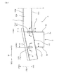
本発明の実施例に係るレインフォースメントおよびバンパー装置について、図1〜図5を用いて説明する。なお、全図中、FRは車両前後方向を、FRIは車両前後方向の車両内側を、FROは車両前後方向の車両外側を意味する。また、Wは車両幅方向を、WIは車両幅方向の車両内側を、WOは車両幅方向の車両外側を意味する。また、UDは車両上下方向を、Uは車両上側を、Dは車両下側を意味する。これら符号は以下の説明において適宜使用する。なお、本例のレインフォースメント、バンパー装置は、車両のフロントバンパー側への適用を想定したものであるが、これに限定されることなく、本例のレインフォースメント、バンパー装置は、車両のリヤバンパー側へも適用することができる。
Example 1
A reinforcement and a bumper device according to an embodiment of the present invention will be described with reference to FIGS. In all the drawings, FR means the vehicle front-rear direction, FRI means the vehicle inner side in the vehicle front-rear direction, and FRO means the vehicle outer side in the vehicle front-rear direction. W represents the vehicle width direction, WI represents the vehicle inner side in the vehicle width direction, and WO represents the vehicle outer side in the vehicle width direction. Moreover, UD means the vehicle vertical direction, U means the vehicle upper side, and D means the vehicle lower side. These symbols are used as appropriate in the following description. Note that the reinforcement and bumper device in this example are assumed to be applied to the front bumper side of the vehicle. However, the reinforcement and bumper device in this example are not limited to this. It can also be applied to the bumper side.
<レインフォースメント>
本例のレインフォースメント1は、車両としての自動車のバンパー補強用であり、図1、図2に示すように、アルミニウム合金材製の中空形材からなり、車両衝突時の衝撃を吸収する衝撃吸収部材2が固定されるものである。
<Rainforce>
The
レインフォースメント1を構成する中空形材には、耐力320MPaのアルミニウム合金材であるA7N01−T6を用いた。レインフォースメント1は、車両幅方向Wに延設されるものであり、車両幅方向Wと10°の角度を持つように車両前後方向の車両内側FRIに向かって両端部側が折り曲げられて形成された曲げ部11を有している。レインフォースメント1の曲げ部11における車両前後方向の車両内側FRIの側壁面12cに、衝撃吸収部材2の一端が固定される。
A7N01-T6, which is an aluminum alloy material having a proof stress of 320 MPa, was used as the hollow material constituting the
なお、図1は、フロントバンパー側に適用した場合におけるレインフォースメント1、後述するバンパー装置3の左側半分を示したものである。図1中、中心線Sの右側には、レインフォースメント1、バンパー装置3の車両前方向の左側半分と左右対称なレインフォースメント1、バンパー装置3の車両前方向の右側半分(不図示)が存在している。したがって、本例のレインフォースメント1は、各曲げ部11に一つずつ衝撃吸収部材2が固定されるものである。また、後述するバンパー装置3も、衝撃吸収部材2を2つ有していることになる。
FIG. 1 shows the
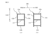
レインフォースメント1は、具体的には、押出による中空形材からなる。この中空形材は、図2(a)に示すように、車両前後方向FRで切断したときの断面形状が略「日」の字状となるように形成されている。すなわち、レインフォースメント1を構成する中空形材は、車両前後方向FRに略平行な一対の側壁面12a、12bと、車両上下方向UDに略平行な一対の側壁面12c、12dとから略角筒形状に構成されている。そして、車両上下方向UDに略平行な一対の側壁面12c、12dの内面間は、車両前後方向FRに略平行な中央リブ13によって連結されている。
Specifically, the
なお、本例では、略「日」の字状断面形状における、車両上下方向UDに略平行な側壁面12c、12dの寸法は100mm、厚みは4mm、車両前後方向FRに略平行な側壁面12a、12bの寸法は80mm、厚みは2mm、中央リブの厚みは2mmとした。また、図2(b)に示すように、レインフォースメント1は、車両前後方向の車両内側FRIの側壁面12c、車両前後方向の車両外側FROの側壁面12dが、車両上下方向の車両上側Uの側壁面12a、車両上下方向の車両下側Dの側壁面12bから突出していてもよい。
In this example, the side wall surfaces 12c and 12d that are substantially parallel to the vehicle vertical direction UD have a dimension of 100 mm, a thickness of 4 mm, and a
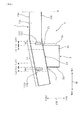
ここで、本例のレインフォースメント1は、図1に示すように、衝撃吸収部材2の固定部14における、車両前後方向FRに略平行な少なくとも1以上の側壁面(本例では側壁面12a、側壁面12b)に、車両前後方向FRに延びる少なくとも1以上の溝部(本例では内側溝部151、外側溝部152)から構成される溝状ビード部15が形成されている。
Here, as shown in FIG. 1, the
溝状ビード部15は、衝撃吸収部材2における車両幅方向の車両内側WIの側壁面2cが接する接点Ciを通る車両前後方向FRの延長線Li上に形成される内側溝部151と、衝撃吸収部材2における車両幅方向の車両外側WOの側壁面2dが接する接点Coを通る車両前後方向FRの延長線Lo上に形成される外側溝部152とを有している。なお、本例では、内側溝部151の長手方向中心線Miと延長線Li、外側溝部152の長手方向中心線Moと延長線Loとをほぼ一致させた。
The groove-shaped
また、内側溝部151は、車両前後方向の車両内側FRIにある側壁面12c側から車両前後方向の車両外側FROに向かって延びるように形成した。一方、外側溝部152は、車両前後方向の車両外側FROにある側壁面12d側から車両前後方向の車両内側FRIに向かって延びるように形成した。
The
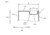
本例のレインフォースメント1において、溝状ビード部15は、上記の通り、内側溝部151、外側溝部152の2つの溝部から構成されている。図3、図4に示すように、これら各溝部151、152の底部154の長さti、toは、側壁面12a(12b)の車両前後方向FRの寸法Tの1/2以下に設定されている。本例のレインフォースメント1では、具体的には、各溝部151、152の底部154の長さti、toを30mm
としたので、ti、toは、T=80/cos10°−2×肉厚(4mm)=73.23mmの1/2以下となっている。なお、図1、図3、図4に示すように、「側壁面の車両前後方向の寸法」には、側壁面12cと側壁面12dの車両前後方向FRの寸法分は含まれない。
In the
Therefore, ti and to are 1/2 or less of T = 80 / cos 10 ° −2 × thickness (4 mm) = 73.23 mm. As shown in FIGS. 1, 3, and 4, “the dimension of the side wall surface in the vehicle longitudinal direction” does not include the dimension of the
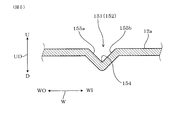
本例のレインフォースメント1において、内側溝部151、外側溝部152は、図5に示すように、各溝部151、152の底部154の長さにわたって、断面形状が略「V」字状に形成されている。つまり、内側溝部151、外側溝部152は、各溝部の底部154の長さにわたり、各溝部の底部154に向かって傾斜する2つの傾斜面155a、155bを有している。このような形状の内側溝部151、外側溝部152は、押出成形法により形成した中空形材に対してプレス成形を施すことにより形成した。なお、内側溝部151、外側溝部152の幅は、ともに10mmとした。また、内側溝部151、外側溝部152の深さは、ともに5mmとした。
In the
<バンパー装置>
本例のバンパー装置3は、図1に示すように、上述したレインフォースメント1と、レインフォースメント1に固定された衝撃吸収部材2とを有している。
<Bumper device>
As shown in FIG. 1, the
バンパー装置3は、具体的には、レインフォーメント1の両端部に形成した各曲げ部11に、アルミニウム合金材製の中空形材を衝撃吸収部とする衝撃吸収部材2の一端の全周が溶接によりそれぞれ固定されている。上記アルミニウム合金材には、耐力280MPaのA6061−T6を用いた。
Specifically, the
衝撃吸収部材2は、車両幅方向Wで切断したときの断面形状が略矩形状であり、車両幅方向Wに略平行な一対の側壁面2a、2b(側壁面2bは図示されず、以下、説明を省略)と、車両上下方向UDに略平行な一対の側壁面2c、2dとから略角筒形状に構成されている。衝撃吸収部材2の幅(車両幅方向Wの寸法)は、110mmとした。衝撃吸収部材2の高さ(車両上下方向UDの寸法)は、90mmとした。
The
バンパー装置3では、衝撃吸収部材2の側壁面2a〜2dのうち、車両幅方向の車両内側WIにある側壁面2cとレインフォースメント1の側壁面12a、12bとの接点Ci(側壁面12b側の接点Ciは図示されず)を通る延長線Li上に、溝状ビード部15の内側溝部151が配置されている。一方、衝撃吸収部材2の側壁面2a〜2dのうち、車両幅方向Wの車両外側WOにある側壁面2dとレインフォースメント1の側壁面12a、12bとの接点Co(側壁面12b側の接点Coは図示されず)を通る延長線Lo上に、溝状ビード部15の外側溝部152が配置されている。なお、本例では、内側溝部151の長手方向中心線Miと延長線Li、外側溝部152の長手方向中心線Moと延長線Loとはほぼ一致させた。
In the
<衝突性能評価>
以下、衝突性能評価を行うため、図1に示す形状のレインフォースメント1を適用したバンパー装置3について、市販のFEM解析ソフトによるシミュレーションを実行した。
<Collision performance evaluation>
Hereinafter, in order to evaluate the collision performance, a simulation using commercially available FEM analysis software was performed on the
先ず、図1に示す形状のレインフォースメント1を適用したバンパー装置3をメッシュモデル化し、解析モデルを作成した。次に、解析モデルに以下の特性を入力した。
すなわち、レインフォースメント1は、耐力320MPaのアルミニウム合金材(A7N01−T6)製の中空押出形材から構成され、衝撃吸収部材2は、耐力280MPaのアルミニウム合金材(A6016−T6)から構成されることを想定し、各耐力を想定した応力−ひずみ特性を解析モデルに入力した。
First, the
That is, the
また、レインフォースメント1を車両前後方向FRで切断したときの断面形状は、略「日」の字状とした。略「日」の字状断面形状における、車両上下方向UDに略平行な側壁面12c、12dの寸法は100mm、厚みは4mm、車両前後方向FRに略平行な側壁面12a、12bの寸法は80mm、厚みは2mm、中央リブの厚みは2mmとした。また、レインフォースメント1は、車両幅方向Wと10°の角度を持つように両端部が曲げ加工された状態とした。また、レインフォースメント1は、車両前後方向FRに略平行な側壁面12a、12bの双方に溝状ビード部15を有しており、内側溝部151、外側溝部153の底部154の長さは、40mm、幅10mm、深さ5mmとした。
Further, the cross-sectional shape when the
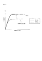
次に、上記特性を入力した解析モデルに対し、図6に示すように、メッシュモデル化した負荷治具4を衝突させるシミュレーションを行った。上記解析モデルによる解析条件として、ODB(Offset Deformable Barrier)を参照した条件を入力した。具体的には、バンパー装置3に固定される衝撃吸収部材2の他端側(車両本体フレーム側)を完全拘束し、負荷治具4を、1000mm/sの速度設定でレインフォースメント1の全長Dの40%の領域に衝突させ、負荷治具4の変位量に対するバンパー装置3への衝突による負荷治具4への反力、および、レインフォースメント1の車両前後方向FRに略平行な側壁面12a、12bの変形形態を出力するシミュレーションを行った。
Next, as shown in FIG. 6, a simulation was performed in which the mesh modeled
なお、比較として、図10に示すように、車両前後方向FRに略平行な側壁面12a、12bに溝状ビード部15を全く形成しなかった点以外は、図1と同様のレインフォースメント91を用いたバンパー装置93(比較品1)について、上記と同様のシミュレーションを行った。
For comparison, as shown in FIG. 10, the
シミュレーション結果を図7に示す。図7において、衝撃エネルギー吸収量は、負荷治具の変位量×荷重の領域の面積で算出される。図7に示すように、比較品1のバンパー装置93は、車両前後方向FRの側壁面12a、12bに溝状ビード部15を有していないレインフォースメント91を用いている。そのため、図10の破線Hの位置にて、車両前後方向FRの側壁面12a、12bが座屈変形し、折れが発生した。これに対し、発明品のバンパー装置3は、車両前後方向FRの側壁面12a、12bに溝状ビード部15を有するレインフォースメント1を用いている。そのため、車両前後方向FRの側壁面12a、12bに座屈変形が生じず、衝撃吸収部材2に衝撃エネルギーが確実に伝達された。
The simulation result is shown in FIG. In FIG. 7, the impact energy absorption amount is calculated by the amount of displacement of the load jig × the area of the load region. As shown in FIG. 7, the
以上から、実施例1のレインフォースメント1は、7000系アルミニウム合金材を用いているにも関わらず、車両衝突時に座屈変形を抑制可能なことがわかる。また、実施例1のレインフォースメント1を用いた実施例1のバンパー装置3は、車両衝突時にレインフォースメント1に座屈変形が生じないので、衝撃吸収特性に優れていることがわかる。
From the above, it can be seen that the
(実施例2)
本例は、図8に示すように、実施例1のレインフォースメント1における溝状ビード部15を構成する内側溝部151、外側溝部152の形成位置を車両幅方向Wにずらした例である。
(Example 2)
In this example, as shown in FIG. 8, the formation positions of the
本例のレインフォースメント1は、内側溝部151の長手方向中心線Miが、衝撃吸収部材2における車両幅方向の車両内側WIの側壁面2cが接する接点Ciを通る車両前後方向FRの延長線Li±車両幅方向20mm(但し、車両幅方向の車両内側WIを+側、車両外側WOを−側とする。)の範囲内に存在している。また、外側溝部152の長手方向中心線Moが、衝撃吸収部材2における車両幅方向の車両外側WOの側壁面2dが接する接点Coを通る車両前後方向FRの延長線Lo±車両幅方向20mm(但し、車両幅方向の車両内側WIを+側、車両外側WOを−側とする。)の範囲内に存在している。
In the
具体的には、本例のレインフォースメント1において、内側溝部151の長手方向中心線Miは、衝撃吸収部材2における車両幅方向の車両内側WIの側壁面2cが接する接点Ciを通る車両前後方向の延長線Liよりも車両幅方向の車両内側WIに12mmずれた位置にある。なお、図8中、Li(+)は、車両前後方向の延長線Liよりも車両幅方向の車両内側WIに20mmずれた位置である。また、Li(−)は、車両前後方向の延長線Liよりも車両幅方向の車両外側WOに20mmずれた位置である。
Specifically, in the
一方、外側溝部152の長手方向中心線Moは、衝撃吸収部材2における車両幅方向の車両外側WOの側壁面2dが接する接点Coを通る車両前後方向FRの延長線Loよりも車両幅方向の車両外側WOに8mmずれた位置にある。なお、図8中、Lo(+)は、車両前後方向の延長線Loよりも車両幅方向の車両内側WIに20mmずれた位置である。また、Lo(−)は、車両前後方向の延長線Loよりも車両幅方向の車両外側WOに20mmずれた位置である。その他の構成は、実施例1のレインフォースメント1と同様である。また、本例のバンパー装置3は、本例のレインフォースメント1を用いた点以外は、実施例1のバンパー装置3と同様の構成を有する。
On the other hand, the longitudinal center line Mo of the
このように構成した場合も、車両衝突時に座屈変形を抑制可能なレインフォースメント、衝撃吸収特性に優れたバンパー装置が得られる。 Even in such a configuration, a bumper device excellent in reinforcement and shock absorption characteristics capable of suppressing buckling deformation at the time of a vehicle collision can be obtained.
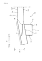
(実施例3)
本例は、図9に示すように、実施例1のレインフォースメント1において、溝状ビード部15を構成する内側溝部151と外側溝部152との間に、さらに、中間溝部153を形成した例である。
(Example 3)
In this example, as shown in FIG. 9, in the
具体的には、本例のレインフォースメント1において、中間溝部153は、内側溝部151および外側溝部152から車両幅方向Wに等距離の位置に形成されている。また、中間溝部153は、側壁面12aの車両前後方向FRの寸法Tの中間から、車両前後方向の車両内側FRIおよび車両外側FROに等距離分だけ延びるように形成されている。その他の構成は、実施例1のレインフォースメント1と同様である。また、本例のバンパー装置3は、本例のレインフォースメント1を用いた点以外は、実施例1のバンパー装置3と同様の構成を有する。
Specifically, in the
このように構成した場合も、車両衝突時に座屈変形を抑制可能なレインフォースメント、衝撃吸収特性に優れたバンパー装置が得られる。 Even in such a configuration, a bumper device excellent in reinforcement and shock absorption characteristics capable of suppressing buckling deformation at the time of a vehicle collision can be obtained.
なお、本例では、中間溝部153を上記のように配置したが、これに限定されるものではなく、内側溝部151と外側溝部152との間に中間溝部153を適宜配置することができる。好ましくは、図10に示すような、割れが想定される位置である破線Hと重なるように配置するとよい。車両衝突時にレインフォースメント1の座屈変形を抑制しやすくなるからである。
In this example, the
以上、実施例について説明したが、本発明は、上記実施例により限定されるものではなく、本発明の趣旨を逸脱しない範囲内で種々の改変が可能なものである。 Although the embodiments have been described above, the present invention is not limited to the above embodiments, and various modifications can be made without departing from the spirit of the present invention.
1 レインフォースメント
11 曲げ部
12a 側壁面(車両上側)
12b 側壁面(車両下側)
12c 側壁面(車両内側)
12d 側壁面(車両外側)
14 固定部
15 溝状ビード部
151 内側溝部
152 外側溝部
154 底部
155a、155b 傾斜面
2 衝撃吸収部材
3 バンパー装置
T 車両前後方向に略平行な側壁面の車両前後方向の寸法(内寸)
ti 内側溝部の底部の長さ
to 外側溝部の底部の長さ
Li 延長線(車両内側)
Lo 延長線(車両外側)
Mi 中心線(内側溝部)
Mo 中心線(外側溝部)
1
12b Side wall surface (vehicle lower side)
12c Side wall (vehicle inside)
12d Side wall surface (vehicle outside)
14
ti Length of bottom of inner groove to length of bottom of outer groove Li Extension line (vehicle inside)
Lo extension line (vehicle outside)
Mi center line (inner groove)
Mo center line (outer groove)
Claims (6)
上記アルミニウム合金材は、耐力300MPa以上の7000系アルミニウム合金材であり、
上記衝撃吸収部材の固定部における、車両前後方向に略平行な少なくとも1以上の側壁面には、車両前後方向に延びる少なくとも1以上の溝部から構成される溝状ビード部が形成されており、
上記溝部の底部の長さは、上記側壁面の車両前後方向の寸法の1/2以下に設定されていることを特徴とするレインフォースメント。 A reinforcement for bumper reinforcement of a vehicle, comprising a hollow shape member made of an aluminum alloy material, to which a shock absorbing member for absorbing a shock at the time of a vehicle collision is fixed,
The aluminum alloy material is a 7000 series aluminum alloy material having a yield strength of 300 MPa or more,
A groove-shaped bead portion composed of at least one groove portion extending in the vehicle front-rear direction is formed on at least one side wall surface substantially parallel to the vehicle front-rear direction in the fixed portion of the shock absorbing member,
The length of the bottom of the groove is set to be 1/2 or less of the dimension of the side wall surface in the vehicle front-rear direction.
上記溝状ビード部は、
上記衝撃吸収部材における車両幅方向の車両内側の側壁面が接する接点を通る車両前後方向の延長線周辺に形成される内側溝部と、
上記衝撃吸収部材における車両幅方向の車両外側の側壁面が接する接点を通る車両前後方向の延長線周辺に形成される外側溝部とを有することを特徴とするレインフォースメント。 The reinforcement according to claim 1,
The groove-shaped bead portion is
An inner groove portion formed around the extension line in the vehicle front-rear direction passing through a contact point where the side wall surface on the vehicle inner side in the vehicle width direction in the impact absorbing member contacts;
A reinforcement having an outer groove formed around an extension line in the vehicle front-rear direction passing through a contact point where a side wall surface on the vehicle outer side in the vehicle width direction of the impact absorbing member contacts.
上記内側溝部は、車両前後方向の車両内側にある側壁面側から車両前後方向の車両外側に向かって延びており、
上記外側溝部は、車両前後方向の車両外側にある側壁面側から車両前後方向の車両内側に向かって延びていることを特徴とするレインフォースメント。 In the reinforcement according to claim 2,
The inner groove portion extends from the side wall surface side on the vehicle inner side in the vehicle front-rear direction toward the vehicle outer side in the vehicle front-rear direction,
The outer groove portion extends from the side wall surface side on the vehicle outer side in the vehicle front-rear direction toward the vehicle inner side in the vehicle front-rear direction.
上記内側溝部の長手方向中心線は、上記衝撃吸収部材における車両幅方向の車両内側の側壁面が接する接点を通る車両前後方向の延長線±車両幅方向20mm(但し、車両幅方向の車両内側を+側、車両外側を−側とする。)の範囲内に存在しており、
上記外側溝部の長手方向中心線は、上記衝撃吸収部材における車両幅方向の車両外側の側壁面が接する接点を通る車両前後方向の延長線±車両幅方向20mm(但し、車両幅方向の車両内側を+側、車両外側を−側とする。)の範囲内に存在していることを特徴とするレインフォースメント。 In the reinforcement according to any one of claims 1 to 3,
The longitudinal center line of the inner groove portion is an extension line in the vehicle front-rear direction passing through a contact point where the side wall surface in the vehicle width direction of the shock absorbing member contacts ± 20 mm in the vehicle width direction (however, the vehicle inner side in the vehicle width direction + Side, the outside of the vehicle is the-side)),
The longitudinal center line of the outer groove portion is an extension line in the vehicle front-rear direction passing through a contact point where the vehicle outer side wall surface in the vehicle width direction of the shock absorbing member contacts ± 20 mm in the vehicle width direction (however, the vehicle inner side in the vehicle width direction Reinforcement characterized by existing within a range of + side and vehicle outside-side.
上記溝部は、該溝部の底部に向かって傾斜する2つの傾斜面を有することを特徴とするレインフォースメント。 In the reinforcement according to any one of claims 1 to 4,
The groove portion has two inclined surfaces inclined toward the bottom portion of the groove portion.
Priority Applications (1)
| Application Number | Priority Date | Filing Date | Title |
|---|---|---|---|
| JP2011055756A JP2012188092A (en) | 2011-03-14 | 2011-03-14 | Reinforcement and bumper device |
Applications Claiming Priority (1)
| Application Number | Priority Date | Filing Date | Title |
|---|---|---|---|
| JP2011055756A JP2012188092A (en) | 2011-03-14 | 2011-03-14 | Reinforcement and bumper device |
Publications (1)
| Publication Number | Publication Date |
|---|---|
| JP2012188092A true JP2012188092A (en) | 2012-10-04 |
Family
ID=47081711
Family Applications (1)
| Application Number | Title | Priority Date | Filing Date |
|---|---|---|---|
| JP2011055756A Withdrawn JP2012188092A (en) | 2011-03-14 | 2011-03-14 | Reinforcement and bumper device |
Country Status (1)
| Country | Link |
|---|---|
| JP (1) | JP2012188092A (en) |
-
2011
- 2011-03-14 JP JP2011055756A patent/JP2012188092A/en not_active Withdrawn
Similar Documents
| Publication | Publication Date | Title |
|---|---|---|
| US9180828B2 (en) | Vehicle body front structure | |
| US9663147B2 (en) | Vehicle body front structure of a vehicle | |
| JP5487236B2 (en) | Car body side structure | |
| JP6128569B2 (en) | Impact energy absorption structure for vehicles | |
| CN106795933B (en) | Impact absorbing member | |
| JP5420462B2 (en) | Automotive parts | |
| JP6176468B2 (en) | Auto body structure | |
| WO2016019107A1 (en) | Lightweight extruded aluminum bumper | |
| JP2015147536A (en) | Vehicular bumper beam | |
| JP5106073B2 (en) | Automotive bumper reinforcement | |
| JP2001199292A (en) | Bumper reinforcement | |
| JP2012126166A (en) | Reinforcing structure in vehicle body skeleton for automobile | |
| JP2010023658A (en) | Bumper reinforcement and method of manufacturing the same | |
| US20220242347A1 (en) | Bumper arrangement with additional support | |
| JP6016246B2 (en) | Auto body structure | |
| JP5875449B2 (en) | Bumper member for vehicles | |
| JP6365632B2 (en) | Vehicle shock absorption structure | |
| JP2017088127A (en) | Vehicle front structure | |
| JP2010089783A (en) | Bumper structure for passenger car | |
| KR20120118276A (en) | The crash box used a car | |
| JP2018111378A (en) | Vehicle bumper structure | |
| JP2012188092A (en) | Reinforcement and bumper device | |
| JP5918092B2 (en) | Bumper beam for vehicles | |
| JP4904334B2 (en) | Energy absorption member for automobile | |
| JP2011011658A (en) | Hood panel and vehicle front section structure excellent in pedestrian protection property |
Legal Events
| Date | Code | Title | Description |
|---|---|---|---|
| A711 | Notification of change in applicant |
Free format text: JAPANESE INTERMEDIATE CODE: A712 Effective date: 20131023 |
|
| A300 | Withdrawal of application because of no request for examination |
Free format text: JAPANESE INTERMEDIATE CODE: A300 Effective date: 20140603 |