EP3623795B1 - Analyse de matière non invasive - Google Patents
Analyse de matière non invasive Download PDFInfo
- Publication number
- EP3623795B1 EP3623795B1 EP19205368.4A EP19205368A EP3623795B1 EP 3623795 B1 EP3623795 B1 EP 3623795B1 EP 19205368 A EP19205368 A EP 19205368A EP 3623795 B1 EP3623795 B1 EP 3623795B1
- Authority
- EP
- European Patent Office
- Prior art keywords
- light beam
- skin
- optical medium
- excitation light
- measurement light
- Prior art date
- Legal status (The legal status is an assumption and is not a legal conclusion. Google has not performed a legal analysis and makes no representation as to the accuracy of the status listed.)
- Active
Links
- 239000000126 substance Substances 0.000 title claims description 71
- 238000004458 analytical method Methods 0.000 title description 14
- 230000005284 excitation Effects 0.000 claims description 131
- 230000003287 optical effect Effects 0.000 claims description 122
- 238000005259 measurement Methods 0.000 claims description 66
- 238000010521 absorption reaction Methods 0.000 claims description 47
- 238000000034 method Methods 0.000 claims description 41
- 210000004369 blood Anatomy 0.000 claims description 28
- 239000008280 blood Substances 0.000 claims description 28
- WQZGKKKJIJFFOK-GASJEMHNSA-N Glucose Natural products OC[C@H]1OC(O)[C@H](O)[C@@H](O)[C@@H]1O WQZGKKKJIJFFOK-GASJEMHNSA-N 0.000 claims description 26
- 239000008103 glucose Substances 0.000 claims description 26
- 239000007788 liquid Substances 0.000 claims description 13
- 239000000203 mixture Substances 0.000 claims description 13
- 239000000839 emulsion Substances 0.000 claims description 11
- 239000004615 ingredient Substances 0.000 claims description 7
- 102000004169 proteins and genes Human genes 0.000 claims description 7
- 108090000623 proteins and genes Proteins 0.000 claims description 7
- XLYOFNOQVPJJNP-UHFFFAOYSA-N water Substances O XLYOFNOQVPJJNP-UHFFFAOYSA-N 0.000 claims description 3
- 239000000463 material Substances 0.000 description 46
- 210000003491 skin Anatomy 0.000 description 37
- 239000010410 layer Substances 0.000 description 17
- 238000001228 spectrum Methods 0.000 description 13
- 238000000862 absorption spectrum Methods 0.000 description 10
- 239000000523 sample Substances 0.000 description 10
- 239000004744 fabric Substances 0.000 description 7
- 230000006870 function Effects 0.000 description 6
- 210000001519 tissue Anatomy 0.000 description 6
- 230000003595 spectral effect Effects 0.000 description 5
- 238000011088 calibration curve Methods 0.000 description 4
- 238000001514 detection method Methods 0.000 description 4
- 210000003722 extracellular fluid Anatomy 0.000 description 4
- 210000004927 skin cell Anatomy 0.000 description 4
- 239000007787 solid Substances 0.000 description 4
- 238000004867 photoacoustic spectroscopy Methods 0.000 description 3
- 229920006254 polymer film Polymers 0.000 description 3
- 230000035945 sensitivity Effects 0.000 description 3
- LFQSCWFLJHTTHZ-UHFFFAOYSA-N Ethanol Chemical compound CCO LFQSCWFLJHTTHZ-UHFFFAOYSA-N 0.000 description 2
- 239000011358 absorbing material Substances 0.000 description 2
- 230000007423 decrease Effects 0.000 description 2
- 230000001419 dependent effect Effects 0.000 description 2
- 238000010586 diagram Methods 0.000 description 2
- 239000003925 fat Substances 0.000 description 2
- NOESYZHRGYRDHS-UHFFFAOYSA-N insulin Chemical compound N1C(=O)C(NC(=O)C(CCC(N)=O)NC(=O)C(CCC(O)=O)NC(=O)C(C(C)C)NC(=O)C(NC(=O)CN)C(C)CC)CSSCC(C(NC(CO)C(=O)NC(CC(C)C)C(=O)NC(CC=2C=CC(O)=CC=2)C(=O)NC(CCC(N)=O)C(=O)NC(CC(C)C)C(=O)NC(CCC(O)=O)C(=O)NC(CC(N)=O)C(=O)NC(CC=2C=CC(O)=CC=2)C(=O)NC(CSSCC(NC(=O)C(C(C)C)NC(=O)C(CC(C)C)NC(=O)C(CC=2C=CC(O)=CC=2)NC(=O)C(CC(C)C)NC(=O)C(C)NC(=O)C(CCC(O)=O)NC(=O)C(C(C)C)NC(=O)C(CC(C)C)NC(=O)C(CC=2NC=NC=2)NC(=O)C(CO)NC(=O)CNC2=O)C(=O)NCC(=O)NC(CCC(O)=O)C(=O)NC(CCCNC(N)=N)C(=O)NCC(=O)NC(CC=3C=CC=CC=3)C(=O)NC(CC=3C=CC=CC=3)C(=O)NC(CC=3C=CC(O)=CC=3)C(=O)NC(C(C)O)C(=O)N3C(CCC3)C(=O)NC(CCCCN)C(=O)NC(C)C(O)=O)C(=O)NC(CC(N)=O)C(O)=O)=O)NC(=O)C(C(C)CC)NC(=O)C(CO)NC(=O)C(C(C)O)NC(=O)C1CSSCC2NC(=O)C(CC(C)C)NC(=O)C(NC(=O)C(CCC(N)=O)NC(=O)C(CC(N)=O)NC(=O)C(NC(=O)C(N)CC=1C=CC=CC=1)C(C)C)CC1=CN=CN1 NOESYZHRGYRDHS-UHFFFAOYSA-N 0.000 description 2
- 235000013336 milk Nutrition 0.000 description 2
- 239000008267 milk Substances 0.000 description 2
- 210000004080 milk Anatomy 0.000 description 2
- SBIBMFFZSBJNJF-UHFFFAOYSA-N selenium;zinc Chemical compound [Se]=[Zn] SBIBMFFZSBJNJF-UHFFFAOYSA-N 0.000 description 2
- 206010020751 Hypersensitivity Diseases 0.000 description 1
- 238000004566 IR spectroscopy Methods 0.000 description 1
- 102000004877 Insulin Human genes 0.000 description 1
- 108090001061 Insulin Proteins 0.000 description 1
- 201000004681 Psoriasis Diseases 0.000 description 1
- 239000008186 active pharmaceutical agent Substances 0.000 description 1
- 235000013334 alcoholic beverage Nutrition 0.000 description 1
- 230000007815 allergy Effects 0.000 description 1
- 235000013405 beer Nutrition 0.000 description 1
- 210000001124 body fluid Anatomy 0.000 description 1
- 239000010839 body fluid Substances 0.000 description 1
- 235000013532 brandy Nutrition 0.000 description 1
- 238000012512 characterization method Methods 0.000 description 1
- 238000006243 chemical reaction Methods 0.000 description 1
- 238000001816 cooling Methods 0.000 description 1
- 230000002596 correlated effect Effects 0.000 description 1
- 239000002537 cosmetic Substances 0.000 description 1
- 239000006059 cover glass Substances 0.000 description 1
- 239000006071 cream Substances 0.000 description 1
- 125000004122 cyclic group Chemical group 0.000 description 1
- 229940079593 drug Drugs 0.000 description 1
- 239000003814 drug Substances 0.000 description 1
- 230000000694 effects Effects 0.000 description 1
- 239000003344 environmental pollutant Substances 0.000 description 1
- 238000011156 evaluation Methods 0.000 description 1
- 239000002360 explosive Substances 0.000 description 1
- 239000000835 fiber Substances 0.000 description 1
- 235000013305 food Nutrition 0.000 description 1
- 239000011521 glass Substances 0.000 description 1
- 238000010438 heat treatment Methods 0.000 description 1
- 238000000338 in vitro Methods 0.000 description 1
- 229940125396 insulin Drugs 0.000 description 1
- 210000002510 keratinocyte Anatomy 0.000 description 1
- 150000002632 lipids Chemical class 0.000 description 1
- 239000006210 lotion Substances 0.000 description 1
- 239000011159 matrix material Substances 0.000 description 1
- 238000002483 medication Methods 0.000 description 1
- 201000001441 melanoma Diseases 0.000 description 1
- 238000012986 modification Methods 0.000 description 1
- 230000004048 modification Effects 0.000 description 1
- 238000012544 monitoring process Methods 0.000 description 1
- 239000002674 ointment Substances 0.000 description 1
- 239000013307 optical fiber Substances 0.000 description 1
- 231100000915 pathological change Toxicity 0.000 description 1
- 230000036285 pathological change Effects 0.000 description 1
- 230000001575 pathological effect Effects 0.000 description 1
- 230000000737 periodic effect Effects 0.000 description 1
- 238000001094 photothermal spectroscopy Methods 0.000 description 1
- 230000010287 polarization Effects 0.000 description 1
- 231100000719 pollutant Toxicity 0.000 description 1
- 229920000642 polymer Polymers 0.000 description 1
- 238000000513 principal component analysis Methods 0.000 description 1
- 239000011541 reaction mixture Substances 0.000 description 1
- 238000011896 sensitive detection Methods 0.000 description 1
- 230000001953 sensory effect Effects 0.000 description 1
- 210000002966 serum Anatomy 0.000 description 1
- 239000000243 solution Substances 0.000 description 1
- 238000010183 spectrum analysis Methods 0.000 description 1
- 239000002344 surface layer Substances 0.000 description 1
- 210000003813 thumb Anatomy 0.000 description 1
- 235000014101 wine Nutrition 0.000 description 1
Images


Classifications
-
- A—HUMAN NECESSITIES
- A61—MEDICAL OR VETERINARY SCIENCE; HYGIENE
- A61B—DIAGNOSIS; SURGERY; IDENTIFICATION
- A61B5/00—Measuring for diagnostic purposes; Identification of persons
- A61B5/145—Measuring characteristics of blood in vivo, e.g. gas concentration, pH value; Measuring characteristics of body fluids or tissues, e.g. interstitial fluid, cerebral tissue
- A61B5/14532—Measuring characteristics of blood in vivo, e.g. gas concentration, pH value; Measuring characteristics of body fluids or tissues, e.g. interstitial fluid, cerebral tissue for measuring glucose, e.g. by tissue impedance measurement
-
- A—HUMAN NECESSITIES
- A61—MEDICAL OR VETERINARY SCIENCE; HYGIENE
- A61B—DIAGNOSIS; SURGERY; IDENTIFICATION
- A61B5/00—Measuring for diagnostic purposes; Identification of persons
- A61B5/145—Measuring characteristics of blood in vivo, e.g. gas concentration, pH value; Measuring characteristics of body fluids or tissues, e.g. interstitial fluid, cerebral tissue
- A61B5/14546—Measuring characteristics of blood in vivo, e.g. gas concentration, pH value; Measuring characteristics of body fluids or tissues, e.g. interstitial fluid, cerebral tissue for measuring analytes not otherwise provided for, e.g. ions, cytochromes
-
- G—PHYSICS
- G01—MEASURING; TESTING
- G01N—INVESTIGATING OR ANALYSING MATERIALS BY DETERMINING THEIR CHEMICAL OR PHYSICAL PROPERTIES
- G01N33/00—Investigating or analysing materials by specific methods not covered by groups G01N1/00 - G01N31/00
- G01N33/48—Biological material, e.g. blood, urine; Haemocytometers
- G01N33/483—Physical analysis of biological material
- G01N33/487—Physical analysis of biological material of liquid biological material
- G01N33/49—Blood
-
- G—PHYSICS
- G01—MEASURING; TESTING
- G01N—INVESTIGATING OR ANALYSING MATERIALS BY DETERMINING THEIR CHEMICAL OR PHYSICAL PROPERTIES
- G01N21/00—Investigating or analysing materials by the use of optical means, i.e. using sub-millimetre waves, infrared, visible or ultraviolet light
- G01N21/17—Systems in which incident light is modified in accordance with the properties of the material investigated
- G01N21/55—Specular reflectivity
- G01N21/552—Attenuated total reflection
-
- A—HUMAN NECESSITIES
- A61—MEDICAL OR VETERINARY SCIENCE; HYGIENE
- A61B—DIAGNOSIS; SURGERY; IDENTIFICATION
- A61B5/00—Measuring for diagnostic purposes; Identification of persons
- A61B5/145—Measuring characteristics of blood in vivo, e.g. gas concentration, pH value; Measuring characteristics of body fluids or tissues, e.g. interstitial fluid, cerebral tissue
- A61B5/1455—Measuring characteristics of blood in vivo, e.g. gas concentration, pH value; Measuring characteristics of body fluids or tissues, e.g. interstitial fluid, cerebral tissue using optical sensors, e.g. spectral photometrical oximeters
-
- A—HUMAN NECESSITIES
- A61—MEDICAL OR VETERINARY SCIENCE; HYGIENE
- A61B—DIAGNOSIS; SURGERY; IDENTIFICATION
- A61B5/00—Measuring for diagnostic purposes; Identification of persons
- A61B5/145—Measuring characteristics of blood in vivo, e.g. gas concentration, pH value; Measuring characteristics of body fluids or tissues, e.g. interstitial fluid, cerebral tissue
- A61B5/1495—Calibrating or testing of in-vivo probes
-
- A—HUMAN NECESSITIES
- A61—MEDICAL OR VETERINARY SCIENCE; HYGIENE
- A61B—DIAGNOSIS; SURGERY; IDENTIFICATION
- A61B5/00—Measuring for diagnostic purposes; Identification of persons
- A61B5/44—Detecting, measuring or recording for evaluating the integumentary system, e.g. skin, hair or nails
- A61B5/441—Skin evaluation, e.g. for skin disorder diagnosis
- A61B5/443—Evaluating skin constituents, e.g. elastin, melanin, water
-
- G—PHYSICS
- G01—MEASURING; TESTING
- G01N—INVESTIGATING OR ANALYSING MATERIALS BY DETERMINING THEIR CHEMICAL OR PHYSICAL PROPERTIES
- G01N21/00—Investigating or analysing materials by the use of optical means, i.e. using sub-millimetre waves, infrared, visible or ultraviolet light
- G01N21/17—Systems in which incident light is modified in accordance with the properties of the material investigated
- G01N21/171—Systems in which incident light is modified in accordance with the properties of the material investigated with calorimetric detection, e.g. with thermal lens detection
-
- G—PHYSICS
- G01—MEASURING; TESTING
- G01N—INVESTIGATING OR ANALYSING MATERIALS BY DETERMINING THEIR CHEMICAL OR PHYSICAL PROPERTIES
- G01N21/00—Investigating or analysing materials by the use of optical means, i.e. using sub-millimetre waves, infrared, visible or ultraviolet light
- G01N21/62—Systems in which the material investigated is excited whereby it emits light or causes a change in wavelength of the incident light
- G01N21/63—Systems in which the material investigated is excited whereby it emits light or causes a change in wavelength of the incident light optically excited
- G01N21/636—Systems in which the material investigated is excited whereby it emits light or causes a change in wavelength of the incident light optically excited using an arrangement of pump beam and probe beam; using the measurement of optical non-linear properties
-
- G—PHYSICS
- G01—MEASURING; TESTING
- G01N—INVESTIGATING OR ANALYSING MATERIALS BY DETERMINING THEIR CHEMICAL OR PHYSICAL PROPERTIES
- G01N33/00—Investigating or analysing materials by specific methods not covered by groups G01N1/00 - G01N31/00
- G01N33/18—Water
-
- G—PHYSICS
- G01—MEASURING; TESTING
- G01N—INVESTIGATING OR ANALYSING MATERIALS BY DETERMINING THEIR CHEMICAL OR PHYSICAL PROPERTIES
- G01N33/00—Investigating or analysing materials by specific methods not covered by groups G01N1/00 - G01N31/00
- G01N33/26—Oils; Viscous liquids; Paints; Inks
- G01N33/28—Oils, i.e. hydrocarbon liquids
- G01N33/2835—Specific substances contained in the oils or fuels
-
- A—HUMAN NECESSITIES
- A61—MEDICAL OR VETERINARY SCIENCE; HYGIENE
- A61B—DIAGNOSIS; SURGERY; IDENTIFICATION
- A61B2560/00—Constructional details of operational features of apparatus; Accessories for medical measuring apparatus
- A61B2560/02—Operational features
- A61B2560/0223—Operational features of calibration, e.g. protocols for calibrating sensors
-
- A—HUMAN NECESSITIES
- A61—MEDICAL OR VETERINARY SCIENCE; HYGIENE
- A61B—DIAGNOSIS; SURGERY; IDENTIFICATION
- A61B2562/00—Details of sensors; Constructional details of sensor housings or probes; Accessories for sensors
- A61B2562/02—Details of sensors specially adapted for in-vivo measurements
- A61B2562/0233—Special features of optical sensors or probes classified in A61B5/00
- A61B2562/0238—Optical sensor arrangements for performing transmission measurements on body tissue
-
- A—HUMAN NECESSITIES
- A61—MEDICAL OR VETERINARY SCIENCE; HYGIENE
- A61B—DIAGNOSIS; SURGERY; IDENTIFICATION
- A61B2562/00—Details of sensors; Constructional details of sensor housings or probes; Accessories for sensors
- A61B2562/02—Details of sensors specially adapted for in-vivo measurements
- A61B2562/0233—Special features of optical sensors or probes classified in A61B5/00
- A61B2562/0242—Special features of optical sensors or probes classified in A61B5/00 for varying or adjusting the optical path length in the tissue
-
- G—PHYSICS
- G01—MEASURING; TESTING
- G01N—INVESTIGATING OR ANALYSING MATERIALS BY DETERMINING THEIR CHEMICAL OR PHYSICAL PROPERTIES
- G01N2201/00—Features of devices classified in G01N21/00
- G01N2201/06—Illumination; Optics
- G01N2201/061—Sources
- G01N2201/06113—Coherent sources; lasers
Definitions
- the present invention relates to a method and a system for the non-invasive analysis of a substance.
- it relates to a method and a system for the non-invasive analysis of a substance from the deflection of a measuring light beam that is reflected in an optical medium applied to the substance.
- the removal or modification of the substance may be undesirable, for example if the reaction means that the substance can no longer be used for its intended purpose or if the removal of part of the substance damages or destroys the substance.
- non-invasive substance analysis can be advantageous, in which the original function or possible use of the substance is not affected by the analysis.
- DE3146700A1 discloses a method related to photoacoustic spectroscopy (PAS), in which the heat sources are detected optically rather than via a sound sensor due to the absorption of an amplitude-modulated light beam, as is the case with PAS.
- PAS photoacoustic spectroscopy
- a second light beam is guided over the sample surface and its influence is measured by temperature- or pressure-dependent, periodic refractive count changes.
- An ATR plate is used to guide the measuring beam, which is placed on the sample as a cover glass. In this plate, the measuring light is guided near the critical angle for total reflection in the plate/sample interface. Changes in the refractive index in the boundary layer due to the absorption of the excitation light beam lead to a detectable modulation of the intensity of the measuring light.
- FARAHI RH ET AL "Pump probe photothermal spectroscopy using quantum cascade lasers" JOURNAL OF PHYSICS D: APPLIED PHYSICS, Vol. 45, No. 12, March 6, 2012, page 125101 reveals the acquisition of information about the composition of objects from a distance in chemical and biological sensing. Excitation of mid-infrared (IR) molecules by quantum cascade lasers (QCLs) and a pump-probe technique are used in a variation of the photothermal process that can provide spectral fingerprints of substances at a variable distance.
- IR mid-infrared
- QCLs quantum cascade lasers
- pump-probe technique are used in a variation of the photothermal process that can provide spectral fingerprints of substances at a variable distance.
- WMDPTR Wavelength Modulated Differential Photothermal Radiometry
- NA GEORGE ET AL "Fibre optic position sensitive detection of photothermal deflection”
- APPLIED PHYSICS B LASERS AND OPTICS, Vol. 77, No. 1, August 20, 2003, pages 77-80 , discloses the use of an optical fiber as a position-sensitive detector in photothermal deflection technology for thermal characterization of solids.
- the thermal conductivity of an n-type wafer is measured and compared with the values from the literature.
- the present invention is therefore based on the object of providing a method and devices for the non-invasive analysis of a substance.
- the method comprises a step of arranging an optical medium on a material surface so that at least a region of the surface of the optical medium is in contact with the material surface, wherein in the claimed method said material is formed by the skin of a patient.
- the step of arranging the optical medium on a material surface should in particular also include arranging a material surface on the optical medium and generally bringing anything into contact.
- the optical medium can also be designed as a receptacle for a substance or can be firmly connected to a substance.
- the optical medium is a body made of ZnS, ZnSe, Ge or Si, which is transparent in a predetermined wavelength range, preferably in the infrared range or a part of the infrared range.
- the substance is formed in the claimed methods by the skin of a patient, but according to the present disclosure can also be a liquid or a solid or a combination of solid, skin and tissue, such as a glass sample holder with a tissue to be examined on it or a liquid inside.
- the contact mentioned is typically direct contact. “Direct contact” is considered to be contact in which the surfaces of the optical medium and the substance touch each other.
- the above-mentioned step of placing the optical medium on the cloth surface means bringing the surfaces of the optical medium and the cloth into contact.
- the optical medium and the material may each have (substantially) flat surfaces in a region that are brought into contact with one another.
- the method according to the invention further comprises the step of emitting an excitation light beam with an excitation wavelength onto the material surface through the region of the surface of the optical medium which is in contact with the material surface. Furthermore, the method according to the invention includes the step of emitting a measuring light beam through the optical medium onto the area of the surface of the optical medium that is in contact with the material surface, such that the measuring light beam and the excitation light beam are on the interface of the optical Overlap the medium and the fabric surface. Preferably, the measuring light beam and the excitation light beam overlap at the interface of the optical medium and the material surface by 10% to 100% or 50% to 100%, particularly preferably by more than 90% or even 100%.
- the degree of overlap is determined, for example, by determining a first interface region in which 95%, preferably 98%, of the total light intensity of the measuring light beam is incident. Likewise, a second interface region is determined in which between 95%, preferably 98%, of the total light intensity of the excitation light beam impinges. The intersection of the first and second interface regions is then related to the average of the first and second interface regions and results in the degree of overlap.
- the method according to the invention further comprises the step of directly or indirectly detecting a deflection of the reflected measuring light beam as a function of the wavelength of the excitation light beam.
- the deflection can be determined, for example, directly by means of a position-sensitive photodetector (PSD) or indirectly by means of a photodetector, in particular a photodiode, which is arranged behind an iris diaphragm.
- PSD position-sensitive photodetector
- a photodetector in particular a photodiode, which is arranged behind an iris diaphragm.
- the method according to the invention includes the step of analyzing the substance based on the detected deflection of the reflected measuring light beam as a function of the wavelength of the excitation light beam. Analyzing here means in particular measuring or determining parameters that characterize the material composition. Preferably, analyzing includes determining an absorption characteristic of the substance. If the excitation light beam is an infrared light beam, then analyzing preferably includes performing infrared spectroscopy. In the specifically claimed method, analyzing the substance includes determining the patient's blood sugar level, determining a water content of the patient's skin Patients, determining a protein composition of the patient's skin, or determining a protein composition of the patient's skin in different skin layers.
- the method according to the invention is based on the fact that an excitation light beam absorbed in a substance changes the beam path of a measuring light beam through the optical medium.
- the reason for this is that the absorption of the excitation light beam in the material induces an increase in temperature, which locally changes the refractive index or the refractive index of the optical medium in contact with the material and thus deflects the beam path of the measuring light beam.
- the degree of deflection correlates with the degree of absorption of the excitation light beam in the material, so that material components with a characteristic absorption spectrum can be identified via the degree of deflection of the measuring light beam.
- the method preferably includes the step of aligning the measuring light beam so that the measuring light beam is totally reflected at the interface between the optical medium and the material surface.
- the term total reflection is equated with an angle of incidence of the measuring light beam that is greater than the critical angle of total reflection, which is equal to the arcsine of the quotient of the refractive index of the material divided by the Refractive index of the optical medium is.
- the measuring light beam is preferably aligned in such a way that it enables the analysis of a large number of different substances with different optical densities.
- the excitation light beam is preferably designed as an intensity-modulated, in particular pulsed, excitation light beam.
- the modulation frequency in particular the pulse rate, is preferably between 5 and 2000 Hz and particularly preferably between 10 and 1000 Hz or 20 and 700 Hz. If the excitation light beam is designed as a pulsed excitation light beam, the cyclic heating and cooling of the excitation light absorbing generates Material components due to the expansion and shrinkage of the material components pressure and especially heat waves that run through the material and spread into the optical medium and thus also deflect the beam path of the measuring light beam.
- the step of emitting the excitation light beam is repeated for different modulation frequencies and the step of analyzing the substance includes analyzing the substance based on the detected deflections of the measurement light beam as a function of the wavelength and the modulation frequency of the excitation light beam.
- Different modulation frequencies lead to the inclusion of different layers in the absorption process. For example, higher modulation frequencies lead to absorption processes that are closer to the surface, while lower modulation frequencies also include absorption processes in deeper layers. This makes it possible to analyze different layers.
- the step of analyzing the material includes subtracting a value based on a deflection of the measurement light beam detected at a first modulation frequency from a value based on a deflection of the measurement light beam detected at a second modulation frequency was detected, or dividing a value based on a deflection of the measurement light beam that was detected at a first modulation frequency by a value that is based on a deflection of the measurement light beam that was detected at a second modulation frequency.
- the difference or dividing the influence of near-surface layers can be eliminated from absorption processes that take place in near-surface and deeper layers, so that the contribution of the deeper layers can be determined.
- the step of analyzing the material includes subtracting values based on deflections of the measurement light beam detected at a first modulation frequency for different wavelengths of the excitation light beam from values based on deflections of the measurement light beam were detected at a second modulation frequency for different wavelengths of the excitation light beam, the values particularly preferably being absorption intensity spectral values, or dividing values based on deflections of the measurement light beam, which were detected at a first modulation frequency for different wavelengths of the excitation light beam were, by values based on deflections of the measuring light beam, which were detected at a second modulation frequency for different wavelengths of the excitation light beam, the values being particularly preferred Absorption intensity spectral values are.
- the step of analyzing includes assigning values based on deflections of the measuring light beam detected at different modulation frequencies to different areas in the fabric, preferably areas in the fabric at different depths.
- assigning or associating the values with material areas a distribution of a substance in the material can be provided, in particular a depth profile of the presence of a substance.
- determining the deflection of the measurement light beam includes amplifying an associated measurement signal with a lock-in amplifier.
- a pulsed excitation light beam in combination with a lock-in amplifier, even small signals or signal changes that are in the noise range can be detected.
- the pulsed excitation light beam is preferably modulated by an optical chopper.
- the optical chopper is preferably coupled to the lock-in amplifier.
- the pulsed excitation light beam can be generated by a pulsed excitation light source.
- the excitation light beam is preferably focused on the surface of the optical medium by an optical device, the optical device in particular comprising a parabolic mirror.
- the optical device is preferably adjusted using an adjustment laser that emits visible light.
- the laser beam of the adjustment laser can be aligned by a mirror arrangement so that the beam path of the adjustment laser beam at least partially coincides with the beam path of the excitation light beam.
- the wavelength of the excitation light beam is varied, in particular by cyclically tuning the wavelength within a predetermined wavelength range or by using characteristic wavelengths, in particular absorption wavelengths of a suspected substance.
- a spectral analysis can be carried out, which makes it possible to distinguish between material components with partially similar or overlapping absorption spectra.
- the predetermined wavelength range can be varied, for example, by using a tunable light source.
- the excitation light beam is an excitation laser beam.
- an excitation laser beam By using an excitation laser beam, the absorption region or an absorption spectrum can be analyzed with high resolution.
- a quantum cascade laser can preferably be used as the excitation laser.
- the measuring light beam is preferably a measuring laser beam.
- the wavelength of the measuring light beam is preferably in the visible wavelength range.
- the excitation wavelength is preferably in a range from 6 ⁇ m to 13 ⁇ m, particularly preferably from 8 ⁇ m to 11 ⁇ m.
- the polarization of the measuring light beam is preferably adjusted so that the deflection of the reflected measuring light beam is maximum.
- the measuring light beam is totally reflected at least one more time, preferably two to five more times, at the same location on the interface of the optical medium before the deflection is detected.
- the measuring light beam is totally reflected at least one more time, preferably two to five more times, at the same location on the interface of the optical medium before the deflection is detected.
- the measuring light beam is totally reflected at least one more time, preferably two to five more times, at the same location on the interface of the optical medium before the deflection is detected.
- a mirror system This effectively increases the deflection angle, thereby increasing the accuracy of detection of the deflection.
- the method preferably comprises the step of preparing the skin surface by applying and peeling off a strip of tissue to remove dead skin cells, the strip of tissue having a material adhered to the surface of the skin.
- the step of analyzing the substance includes the step of determining the patient's blood sugar level.
- the step of determining the blood sugar level includes the step of measuring the glucose content of the interstitial fluid of the patient's skin.
- the step of analyzing the substance preferably comprises the step of determining a water content of the patient's skin.
- the step of analyzing the substance preferably comprises the step of determining a protein composition of the patient's skin and particularly preferably determining a protein composition of the patient's skin in different skin layers.
- skin layers is intended to mean areas in the skin that extend (essentially) parallel to the skin surface and are arranged above or below one another.
- the wavelength of the excitation light beam is assigned an absorption intensity value based on the detected deflection of the measurement light beam.
- the absorption intensity value can be compared with a calibration absorption intensity value, which represents the absorption intensity value of the patient's skin with a known blood sugar level and this wavelength of the excitation light beam.
- the patient's current blood sugar level is then determined on the basis of the comparison, the determined blood sugar level deviating more from the blood sugar level on which the calibration is based, the more the absorption intensity value deviates from the calibration absorption intensity value.
- the devices according to the invention include an optical medium, a device for emitting one or more excitation light beams with an excitation wavelength and a measuring device.
- the optical medium can be, for example, a body made of ZnS, ZnSe, Ge or Si, which is transparent in a predetermined wavelength range.
- the device for emitting the excitation light beam is arranged such that the emitted excitation light beam penetrates into the optical medium through a first surface and leaves it again through a predetermined point on a second surface. If a substance is arranged on the second surface of the optical medium during operation, the excitation light beam is at least partially absorbed on the surface of the substance or in the substance. The degree of absorption can be detected using a measuring device.
- the measuring device comprises a device for emitting a measuring light beam, which is arranged such that an emitted measuring light beam penetrates into the optical medium and, during operation, overlaps with the excitation light beam on the interface of the optical medium and the material surface.
- the measuring light beam and the excitation light beam overlap at the interface of the optical medium and the material surface by 10% to 100% or 50% to 100%, particularly preferably by more than 90% or even 100%.
- the degree of overlap is determined, for example, by determining a first interface region in which 95%, preferably 98%, of the total light intensity of the measuring light beam is incident.
- a second interface region is determined in which between 95%, preferably 98%, of the total light intensity of the excitation light beam impinges. The intersection of the first and second interface regions is then related to the average of the first and second interface regions and results in the degree of overlap.
- the measuring light beam can strike the interface between the second surface and the material surface at an angle that is smaller than the critical angle of total reflection, the point of impact overlapping with the point of impact of the excitation light beam and preferably coinciding with it.
- the measuring device further comprises a device for receiving the reflected measuring light beam and for directly or indirectly detecting a deflection of the reflected measuring light beam.
- the excitation light beam penetrates into the substance and is absorbed to varying degrees depending on the composition of the substance and the wavelength of the excitation light beam.
- the absorption of the excitation light triggers heat transport and pressure waves, which influence the beam path of the measuring laser beam in the optical medium. Since the influence correlates with the concentration of a material component that absorbs the infrared light, the concentration of the material component can be determined by measuring the degree of deviation of the beam path from an uninfluenced beam path.
- the measuring light beam is preferably totally reflected at the interface between the optical medium and the material surface.
- the excitation light beam is preferably an infrared light beam, since infrared light is characteristically absorbed by many substances and is therefore particularly suitable for substance analysis.
- the excitation light beam is preferably an intensity-modulated, in particular pulsed, excitation light beam.
- the device for receiving the reflected measuring light beam and for directly or indirectly detecting the deflection of the reflected measuring light beam comprises a lock-in amplifier.
- the modulation frequency in particular the pulse rate, is preferably between 5 and 2000 Hz, particularly preferably between 10 and 1000 Hz or 20 and 700 Hz.
- the device for emitting the excitation light beam preferably comprises an optical chopper.
- the optical chopper is placed in the beam path of the excitation light beam and modulates the intensity of the excitation light beam.
- the excitation light beam is an excitation laser beam and the device for emitting the excitation laser beam is set up to emit excitation laser beams of different excitation frequencies.
- the absorption region or an absorption spectrum can be analyzed with high resolution.
- the devices of the invention further comprise an optical device intended to focus the excitation light beam on the predetermined point.
- an optical device intended to focus the excitation light beam on the predetermined point.
- the optical device can include, for example, a parabolic mirror.
- the devices of the invention include an alignment laser which facilitates the alignment of the optical device.
- the system preferably comprises a pair of mirrors which is suitable for aligning the beam path of the adjustment laser so that at least part of the beam path of the adjustment laser coincides with the beam path of the excitation light beam.
- the device for emitting the excitation light beam is a quantum cascade laser.
- the device for emitting the excitation light beam can be tuned in an excitation wavelength range of 6 ⁇ m to 13 ⁇ m, preferably 8 ⁇ m to 11 ⁇ m.
- the wavelength of the measuring light beam is preferably in the visible range. This simplifies the alignment of the measuring light beam with the excitation light beam.
- the device for receiving the reflected measuring light beam and for directly or indirectly detecting the deflection of the reflected measuring light beam preferably comprises a photodetector, in particular a photodiode, and an iris diaphragm, the photodetector being arranged behind the iris diaphragm, or a PSD.
- the measuring light beam is totally reflected at least one more time, preferably two to five more times, at the same location on the interface of the optical medium before the deflection is detected.
- the measuring light beam is totally reflected at least one more time, preferably two to five more times, at the same location on the interface of the optical medium before the deflection is detected.
- the measuring light beam is totally reflected at least one more time, preferably two to five more times, at the same location on the interface of the optical medium before the deflection is detected.
- the measuring light beam is totally reflected at least one more time, preferably two to five more times, at the same location on the interface of the optical medium before the deflection is detected.
- the method and the devices are set up to analyze substances on and in the skin and to record depth-selective profiles of these substances.
- Methods and devices are also suitable for analyzing traces of substances such as pollutants or explosives on the skin. Or to examine the absorption of cosmetics, such as fats and ingredients of creams, ointments or lotions, or active pharmaceutical ingredients, medications, etc. into the skin.
- the device is suitable for sensory applications such as monitoring flowing and stagnant liquids or solutions and emulsions to determine e.g. B. the alcohol content or composition of alcoholic beverages such as beer, wine or brandy, the fat content of milk or milk products, and generally the sugar, fat, alcohol or protein content of foods.
- methods are suitable for the analysis of body fluids and the analysis of pathological and non-pathological changes in the skin, such as the detection of melanomas by determining the protein composition of the skin at different skin depths, the detection of psoriasis or allergies and the determination of skin moisture.
- One embodiment relates to a device for determining the blood sugar level of a patient according to claim 9, which comprises a control for setting different wavelengths of the excitation light beam and a logic or computing unit which is set up to use detected deflections of the measuring light beam as a function of the Excitation wavelength to determine the blood sugar level in the skin of a patient when the optical medium is brought into contact with the patient's skin in such a way that the excitation light beam emerging from the optical medium at said predetermined point penetrates the skin.
- a further embodiment relates to a device for analyzing a substance, which further comprises a control for setting different modulation frequencies of the excitation light beam and a logic or computing unit which is set up to analyze the substance by means of detected deflections of the measuring light beam at different modulation frequencies , when the optical medium is brought into contact with the substance in such a way that the excitation light beam emerging from the optical medium at said predetermined point penetrates into the substance.
- the material is preferably the skin of a patient and the logic or computing unit is set up to analyze different layers of the patient's skin from detected deflections of the measuring light beam at different modulation frequencies.
- a further embodiment relates to a device for analyzing the ingredients of a liquid or emulsion, which further comprises a control for setting different wavelengths of the excitation light beam and a logic or computing unit which is set up to use detected deflections of the measuring light beam as a function of the excitation wavelength to determine ingredients of the liquid or emulsion when the optical medium is brought into contact with the liquid or emulsion in such a way that the excitation light beam emerging from the optical medium at the said predetermined point penetrates into the liquid or emulsion.
- Fig. 1 shows a schematic representation of a preferred embodiment of the system according to the invention in operation.
- the preferred embodiment includes an optical medium 10, a device for emitting an infrared light beam in the form of a quantum cascade laser 20, a device for emitting a measuring light beam in the form of a measuring laser 30 and a device with means for receiving the reflected measuring laser beam with a Photodiode 40 and with means for evaluating the reflected measuring laser beam, which include a lock-in amplifier 50, a digital-to-anlog converter 51 and a computer 52.
- the quantum cascade laser 20 sends an infrared laser beam on a first infrared laser beam partial path 21 through an optical chopper 22, which converts the continuous infrared laser beam into a pulsed infrared laser beam, preferably with a pulse frequency between 10Hz to 1000Hz.
- the device for emitting the infrared light beam here the quantum cascade laser 30, can be operated in pulse mode - also with a pulse frequency of preferably 10 Hz to 1000 Hz.
- the infrared laser beam hits a parabolic mirror 23.
- the parabolic mirror 23 directs the infrared laser beam along a second one Infrared laser beam partial path 24 onto a first surface 11 of the optical medium 10.
- the angle of incidence between the second infrared laser beam partial path 24 and the first surface 11 is in Fig. 1 shown preferred embodiment 90 °. In principle, other angles of incidence between the second infrared laser beam partial path 24 and the first surface 11 are also possible, as long as the infrared laser beam penetrates through the first surface 11 into the optical medium 10 and is not totally reflected.
- the beam path of the infrared laser beam runs in the optical medium 10 along a third infrared laser beam partial path 25 towards a second surface 12 of the optical medium 10.
- the angle of incidence between the third infrared laser beam partial path 25 and the second surface 12 is in Fig. 1 shown preferred embodiment 90 °. In principle, however, other angles of incidence between the third infrared laser beam partial path 25 and the second surface 12 are also possible here, as long as a sufficient proportion of the infrared laser beam can leave the optical medium 10 through the second surface 12.
- the infrared laser beam penetrates along a fourth partial infrared laser beam path into a sample of material 100 which rests on the optical medium 10.
- the distance between the parabolic mirror 23 and the second surface 12 of the optical medium and the shape of the parabolic mirror 23 are selected taking into account the optical densities along the second and third infrared laser beam partial paths 24, 25 so that the infrared laser beam is directed to the second Surface 12 or is focused on a point which lies at a predetermined distance, for example between 30 ⁇ m and 100 ⁇ m, behind the second surface 12 in the fabric sample 100.
- the infrared laser beam is at least partially absorbed by material components. Absorption changes the temperature of the absorbing material component.
- a pulsed infrared laser beam as in Fig. 1 shown, pressure and heat waves are generated because the absorbing material components heat up and cool cyclically and the resulting expansion fluctuations lead to pressure fluctuations that spread through the material in the form of pressure waves. The heat and generated Since the optical medium 10 and the material are in direct contact, pressure waves migrate into the optical medium 10 and influence the refractive index there.
- the measuring laser beam emitted by the measuring laser 30 is used to measure the absorption of the infrared laser beam and the change in the optical density of the optical medium 10 that is correlated with the absorption.
- This one will be in Fig. 1 directed via a first mirror 31 onto a third surface 13 of the optical medium 10.
- the measuring laser 30 can also be aligned so that the measuring laser beam is directed directly onto the third surface 13.
- the beam path of the measuring laser beam can enclose an angle of 90° with the third surface 13.
- the beam path of the measuring laser beam can enclose a smaller angle with the third surface 13, as long as a sufficient proportion of the measuring laser beam can penetrate into the optical medium 10.
- the beam path of the measuring laser beam must be aligned such that the point of impact of the measuring laser beam on the second surface 12 of the optical medium 10 coincides with the point of impact of the infrared light beam on the second surface 12 of the optical medium, or at least overlaps it. This ensures that during operation of the infrared laser beam, the beam path of the measuring laser beam passes through the region of the optical medium 10 described above, in which the refractive index n is sufficiently influenced by the absorption of the infrared laser beam in the material 100, whereby It is clear that this area is limited because the pressure waves are dampened as they propagate and the heat increase decreases with distance from the absorption area.
- the optical density of the optical medium 10 is selected depending on the substance 100 to be examined and the angle between the beam path of the measuring laser beam and the second surface 12 so that the measuring laser beam is at the second surface 12 or at the interface between the second surface 12 of the optical medium 10 and the material 100 is totally reflected.
- the reflected or totally reflected measuring laser beam hits a fourth surface 14 of the optical medium 10 in the further course of the beam path.
- the fourth surface 14 can be designed such that the measuring laser beam leaves the optical medium 10 through the fourth surface 14.
- the measuring laser beam leaving the optical medium 10 is detected by the photodiode 40.
- the deflection of the measuring laser beam by changing the optical density in a partial area of the optical medium 10 can, as in Fig. 1 shown, can be measured by the measuring laser beam passing an iris diaphragm 41 before incident on the photodiode 40.
- the deflected measuring laser beam is then partially prevented from entering the photodiode 40 by the iris diaphragm 41, so that the intensity of the measuring laser beam measured at the photodiode 40 decreases due to the deflection as it passes through the optical medium 10.
- a spatially resolving photodiode 40 for example a four-quadrant photodiode, can be used to measure the change in the beam path or deflection.
- the iris diaphragm 41 can be omitted.
- the lock-in amplifier 50 receives the signal from the photodiode 40 and the frequency signal of the pulsed infrared light beam.
- the lock-in amplifier filters the noise from the intensity signal so that even small fluctuations in intensity can be measured.
- the filtered intensity signal of the photodiode 40 is converted into a digital signal by a digital-to-analog converter 51 and transmitted to a computer 52, which is set up to record the intensity measurement values depending on the wavelength or the wavelength range of the quantum cascade laser 30 and the recorded ones Compare values with a calibration curve in order to be able to draw conclusions about the composition of the substance 100.
- the computer 52 comprises a processor, a memory unit and instructions which, when executed by the processor, record the intensity measurement values linked to the wavelength or the wavelength range of the quantum cascade laser 30.
- the process described above, which in Fig. 7 is shown clearly, is preferably repeated for a number of different wavelengths or wavelength ranges in the infrared light range in order to be able to determine the absorption spectrum of individual or several material components.
- the presence of a substance component can be determined by measuring characteristic absorption spectra and the concentration of the substance component from the amplitude of the spectrum, for example by comparing it with a calibration curve.
- the quantum cascade laser 30 can be tunable, for example, in the wavelength range from 8 ⁇ m to 11 ⁇ m.
- the patient's blood glucose level can be calculated from the measured absorption spectrum of the glucose in the interstitial fluid using a calibration curve.
- the system shown contains a device for emitting an adjustment laser beam, here in the form of a He-Ne laser 60, and a pair of mirrors 61, 62, which aligns the beam path of the adjustment laser so that at least part of the beam path of the adjustment laser coincides with the beam path of the infrared light beam, ie the excitation light beam.
- a device for emitting an adjustment laser beam here in the form of a He-Ne laser 60
- a pair of mirrors 61, 62 which aligns the beam path of the adjustment laser so that at least part of the beam path of the adjustment laser coincides with the beam path of the infrared light beam, ie the excitation light beam.
- the substance to be analyzed is 100 skin and the aim of the analysis is to determine the blood sugar level, for example the ball of the thumb, the fingertip, the heel of the hand or another body surface is brought into contact with the second surface 12 of the optical medium 10.
- the body surface to be brought into contact can be prepared to remove dead skin cells by attaching and removing a strip of tissue, the strip of tissue having a material that adheres to the surface of the skin.
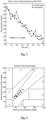
- the spectra of the skin which were measured in this way with the preferred embodiment of the system according to the invention, show the bands of keratinocytes and lipids as the first main component.
- the second main component was the in Fig. 2 glucose bands shown were measured.
- Fig. 3 shows the measured blood sugar values and the blood sugar concentration determined from the amplitude of the second main component.
- the quantum cascade laser 30 can be tuned in the wavelength range from 8 ⁇ m to 11 ⁇ m.
- the patient's blood sugar level is calculated from the measured absorption spectrum of the glucose in the interstitial fluid using a calibration curve.
- the system is permanently attached to the patient, for example in the form of a bracelet, and is further adapted to alert the patient by means of a warning signal when the glucose concentration in the interstitial fluid falls below a predetermined value.
- the system can control an insulin pump to maintain a consistent blood sugar level in the patient.
- the computer 52 can be set up to record the intensity measurements depending on the wavelength or the wavelength range of the quantum cascade laser 30 for different pulse frequencies of the infrared laser beam.
- the computer 52 comprises a processor, a memory unit and instructions which, when executed by the processor, record the intensity measurement values linked to the wavelength or the wavelength range and the pulse frequency of the infrared laser beam.
- Fig. 5 shows intensity measurements measured with the further preferred embodiment in Fig. 6a shown material arrangement, consisting of a glucose solution 64 covered with a polymer film 66, which is arranged on the optical medium 10.
- the comparison of the in Fig. 5 Absorption spectra shown with those in 6b and 6c
- the absorption intensity spectra shown shows that at higher frequencies the influence of the absorption by the polymer film 66 on the qualitative course of the absorption intensity is reduced.
- influences of certain layers can be largely eliminated or absorption intensity spectra of certain material layers can be calculated, so that, for example, a depth profile can be determined with regard to substances present in the material 100.
- the difference or division of the spectra can be done, for example, as in Fig. 5 shown, to a specified reference spectrum.
- the spectrum at the lowest or highest pulse frequency can serve as a reference spectrum.
- the subtraction or division can be preceded by determining weighting factors, whereby the spectra or spectral values to be subtracted from one another or divided by one another are to be multiplied by a weighting factor.
- a principal component analysis according to the Non-Linear Iterative Partial Least Squares (NIPALS) algorithm can be used, for example to determine a substance that is distributed differently in depth in a solid matrix.
Landscapes
- Health & Medical Sciences (AREA)
- Life Sciences & Earth Sciences (AREA)
- Physics & Mathematics (AREA)
- Engineering & Computer Science (AREA)
- General Health & Medical Sciences (AREA)
- Pathology (AREA)
- Chemical & Material Sciences (AREA)
- Biomedical Technology (AREA)
- Analytical Chemistry (AREA)
- Biochemistry (AREA)
- General Physics & Mathematics (AREA)
- Immunology (AREA)
- Molecular Biology (AREA)
- Biophysics (AREA)
- Optics & Photonics (AREA)
- Heart & Thoracic Surgery (AREA)
- Surgery (AREA)
- Veterinary Medicine (AREA)
- Public Health (AREA)
- Medical Informatics (AREA)
- Animal Behavior & Ethology (AREA)
- Hematology (AREA)
- Medicinal Chemistry (AREA)
- Food Science & Technology (AREA)
- Ecology (AREA)
- Urology & Nephrology (AREA)
- Spectroscopy & Molecular Physics (AREA)
- Emergency Medicine (AREA)
- Nonlinear Science (AREA)
- Nuclear Medicine, Radiotherapy & Molecular Imaging (AREA)
- Chemical Kinetics & Catalysis (AREA)
- General Chemical & Material Sciences (AREA)
- Oil, Petroleum & Natural Gas (AREA)
- Dermatology (AREA)
- Investigating Or Analysing Materials By Optical Means (AREA)
- Measurement Of The Respiration, Hearing Ability, Form, And Blood Characteristics Of Living Organisms (AREA)
Claims (14)
- Procédé pour l'analyse de la peau (100) d'un patient, comprenant les étapes suivantes :- disposition d'un milieu optique (10) sur la surface de la peau, de sorte qu'au moins une zone de la surface (12) du milieu optique (10) est en contact avec la surface de la peau ;- émission d'un rayon lumineux d'excitation avec une longueur d'onde d'excitation à travers la zone de la surface (12) du milieu optique (10), qui est en contact avec la surface de la peau, sur la surface de la peau, de sorte que le rayon lumineux d'excitation est absorbé au moins partiellement dans la peau ;- émission d'un rayon lumineux de mesure à travers le milieu optique (10) sur la zone de la surface (12) du milieu optique (10), qui est en contact avec la surface de la peau, de sorte que le rayon lumineux de mesure et le rayon lumineux d'excitation se superposent sur une surface limite du milieu optique (10) et la surface de la peau, au niveau de laquelle le rayon lumineux de mesure est réfléchi, dans lequel un rayon lumineux d'excitation absorbé dans la peau est capable de modifier le trajet de rayon du rayon lumineux de mesure à travers le milieu optique ;- détection d'une déviation du rayon lumineux de mesure réfléchi en fonction de la longueur d'onde du rayon lumineux d'excitation au moins partiellement absorbé, dans lequel le degré de déviation est corrélé avec le degré d'absorption du rayon lumineux d'excitation dans la peau ; et- analyse de la peau (100) à l'aide de la déviation détectée du rayon lumineux de mesure en fonction de la longueur d'onde du rayon lumineux d'excitation au moins partiellement absorbé,dans lequel l'analyse de la peau (100) comprendune détermination de la glycémie du patient,une détermination de la teneur en eau de la peau du patient,une détermination d'une composition en protéines de la peau du patient ouune détermination d'une composition en protéines de la peau du patient dans différentes couches de la peau.
- Procédé selon la revendication 1, comprenant l'étape supplémentaire suivante :orientation du rayon lumineux de mesure de sorte que le rayon lumineux de mesure est réfléchi totalement au niveau de la surface limite entre le milieu optique (10) et la surface de la peau,et/ou dans lequel le rayon lumineux d'excitation est un rayon lumineux infrarouge.
- Procédé selon l'une des revendications précédentes, dans lequel le rayon lumineux d'excitation est un rayon lumineux d'excitation modulé en intensité, plus particulièrement pulsé, dans lequel l'étape d'émission du rayon lumineux d'excitation est répétée pour différentes fréquences de modulation et l'étape d'analyse de la peau (100) comprend l'analyse de la peau (100) à l'aide des déviations détectées du rayon lumineux de mesure en fonction de la longueur et de la fréquence de modulation du rayon lumineux d'excitation.
- Procédé selon l'une des revendications précédentes, dans lequel la longueur d'onde du rayon lumineux d'excitation varie, plus particulièrement- la longueur d'onde est accordée à l'intérieur d'un domaine de longueurs d'ondes prédéterminées ou- des longueurs d'ondes caractéristiques, plus particulièrement des longueurs d'ondes d'absorption d'une substance présumée, sont ajustées de manière ciblée.
- Procédé selon l'une des revendications précédentes, dans lequel le rayon lumineux d'excitation est généré à l'aide d'un laser à cascade quantique (20).
- Procédé selon l'une des revendications précédentes, dans lequel la longueur d'onde d'excitation est choisie dans une plage de 6 µm à 13 µm ; de préférence de 8 µm à 11 µm.
- Procédé selon l'une des revendications précédentes, dans lequel la déviation du rayon lumineux de mesure- est déterminée à l'aide d'un photodétecteur sensible à la position (PSD).
- Procédé selon l'une des revendications précédentes, dans lequel l'analyse de la peau (100) comprend une détermination de la glycémie du patient et dans lequel la valeur d'intensité d'absorption est comparée avec une valeur d'intensité d'absorption de calibrage qui représente la valeur d'intensité d'absorption de la peau d'un patient pour une glycémie connue, et la longueur d'onde du rayon lumineux d'excitation, dans lequel la glycémie actuelle du patient est déterminée de préférence sur la base de la comparaison, dans lequel la glycémie déterminée s'écarte d'autant plus de la glycémie pendant le calibrage que la valeur d'intensité d'absorption s'écarte de la valeur d'intensité d'absorption de calibrage.
- Appareil pour la détermination de la glycémie d'un patient qui comprend ce qui suit :- un milieu optique (10) ;un dispositif (20) pour l'émission d'un rayon lumineux d'excitation avec une longueur d'onde d'excitation,dans lequel le dispositif (20) est conçu pour l'émission du rayon lumineux d'excitation de sorte que le rayon lumineux d'excitation émis pénètre dans le milieu optique (10) et quitte à nouveau celui-ci à un point prédéterminé sur la surface (12) du milieu optique (10) ; etun dispositif de mesure, dans lequel le dispositif de mesure comprend un dispositif (30) pour l'émission d'un rayon lumineux de mesure, qui est conçu de sorte qu'un rayon lumineux de mesure émis pénètre dans le milieu optique (10) et, lors du fonctionnement, le rayon lumineux de mesure et le rayon lumineux d'excitation se superposent sur une surface limite du milieu optique (10) et d'une surface de la peau du patient, au niveau de laquelle le rayon lumineux de mesure est réfléchi,dans lequel le trajet de rayon du rayon lumineux de mesure à travers le milieu optique peut être modifié par un rayon lumineux d'excitation absorbé dans la peau,et dans lequel le dispositif de mesure comprend un dispositif (40, 50, 51, 52) pour la réception du rayon lumineux de mesure réfléchi et pour la détection d'une déviation du rayon lumineux de mesure réfléchi, dans lequel le degré de déviation est corrélé avec le degré d'absorption du rayon lumineux d'excitation dans la peau,- un dispositif de commande pour le réglage de différentes longueurs d'ondes du rayon lumineux d'excitation et- une unité de logique ou de calcul (52), qui est conçue pour déterminer, à partir des déviations détectées du rayon lumineux de mesure en fonction de la longueur d'onde d'excitation, la glycémie dans la peau d'un patient lorsque le milieu optique est mis en contact avec la peau du patient de sorte que le rayon lumineux d'excitation sortant du milieu optique (10) à un point prédéterminé mentionné pénètre dans la peau et y est au moins partiellement absorbé.
- Appareil selon la revendication 9, dans lequel le rayon lumineux de mesure est un rayon lumineux de mesure modulé en intensité, plus particulièrement pulsé, dans lequel le dispositif (40, 41, 50, 51, 52) comprend, de préférence, pour la réception du rayon lumineux de mesure réfléchi et pour la détection directe ou indirecte d'une déviation du rayon lumineux de mesure réfléchi, un amplificateur à verrouillage (50).
- Appareil selon l'une des revendications 9 ou 10, dans lequel le dispositif (20) pour l'émission du rayon lumineux d'excitation peut être accordé dans un domaine de longueurs d'ondes d'excitation de 6 µm à 13 µm, de préférence de 8 µm à 11 µm.
- Appareil selon l'une des revendications 9 à 11, dans lequel le dispositif (40, 41, 50, 51, 52) comprend, pour la réception du rayon lumineux de mesure réfléchi et pour la détection directe ou indirecte d'une déviation du rayon lumineux de mesure réfléchi,- un photodétecteur sensible à la position (PSD).
- Appareil pour l'analyse d'une substance (100) qui comprend ce qui suit :- un milieu optique (10) ;un dispositif (20) pour l'émission d'un rayon lumineux d'excitation avec une longueur d'onde d'excitation,dans lequel le dispositif (20) est conçu pour l'émission du rayon lumineux d'excitation de sorte que le rayon lumineux d'excitation émis pénètre dans le milieu optique (10) et quitte à nouveau celui-ci à un point prédéterminé sur la surface (12) du milieu optique (10) ; etun dispositif de mesure, dans lequel le dispositif de mesure comprend un dispositif (30) pour l'émission d'un rayon lumineux de mesure, qui est conçu de sorte qu'un rayon lumineux de mesure émis pénètre dans le milieu optique (10) et, lors du fonctionnement, le rayon lumineux de mesure et le rayon lumineux d'excitation se superposent sur une surface limite du milieu optique (10) et d'une surface de la substance, au niveau de laquelle le rayon lumineux de mesure est réfléchi, dans lequel le trajet du rayon lumineux de mesure à travers le milieu optique peut être modifié par un rayon lumineux d'excitation absorbé dans la substance,et dans lequel le dispositif de mesure comprend un dispositif (40, 50, 51, 52) pour la réception du rayon lumineux de mesure réfléchi et pour la détection d'une déviation du rayon lumineux de mesure réfléchi, dans lequel le degré de déviation est corrélé avec le degré d'absorption du rayon lumineux d'excitation dans la substance,- un dispositif de commande pour le réglage de différentes longueurs d'ondes du rayon lumineux d'excitation et- une unité de logique ou de calcul (52), qui est conçue pour analyser la substance (100) au moyen de déviations détectées du rayon lumineux de mesure pour des fréquences de modulation différentes, lorsque le milieu optique est mis en contact avec la substance (100) de sorte que le rayon lumineux d'excitation sortant du milieu optique (10) au point prédéterminé mentionné pénètre dans la substance (100) et y est au moins partiellement absorbé, dans lequel la substance (100) est de préférence la peau d'un patient et l'unité logique ou de calcul (52) est conçue pour analyser, à partir des déviations détectées du rayon lumineux de mesure pour différentes fréquences de modulation, différentes couches de la peau du patient.
- Appareil pour l'analyse de composants d'un liquide ou d'une émulsion, qui comprend ce qui suit :- un dispositif (20) pour l'émission d'un rayon lumineux d'excitation avec une longueur d'onde d'excitation,dans lequel le dispositif (20) pour l'émission du rayon lumineux d'excitation est conçu de sorte que le rayon lumineux d'excitation émis pénètre dans le milieu optique (10) et le quitte à nouveau à un point prédéterminé sur la surface (12) du milieu optique (10) ; etun dispositif de mesure, dans lequel le dispositif de mesure comprend un dispositif (30) pour l'émission d'un rayon lumineux de mesure qui est conçu de sorte qu'un rayon lumineux de mesure émis pénètre dans le milieu optique (10) et, lors du fonctionnement, le rayon lumineux de mesure et le rayon lumineux d'excitation se superposent sur une surface limite du milieu optique (10) et une surface de la substance, au niveau de laquelle le rayon lumineux de mesure est réfléchi, dans lequel le trajet du rayon lumineux de mesure à travers le milieu optique peut être modifié par un rayon lumineux d'excitation absorbé dans le liquide ou l'émulsion,et dans lequel le dispositif de mesure comprend un dispositif (40, 50, 51, 52) pour la réception du rayon lumineux de mesure réfléchi et pour la détection d'une déviation du rayon lumineux de mesure réfléchi, dans lequel le degré de déviation est corrélé avec le degré d'absorption du rayon lumineux d'excitation dans le liquide ou l'émulsion,- un dispositif de commande pour le réglage de différentes longueurs d'ondes du rayon lumineux d'excitation et- une unité logique ou de calcul (52), qui est conçue pour déterminer, à partir des déviations détectées du rayon lumineux de mesure en fonction de la longueur d'onde d'excitation, les composants du liquide ou de l'émulsion lorsque le milieu optique est mis en contact avec le liquide ou l'émulsion de sorte que le rayon lumineux d'excitation sortant du milieu optique (10) au point prédéterminé mentionné pénètre dans le liquide ou l'émulsion et y est au moins partiellement absorbé.
Applications Claiming Priority (3)
| Application Number | Priority Date | Filing Date | Title |
|---|---|---|---|
| DE102014108424.1A DE102014108424B3 (de) | 2014-06-16 | 2014-06-16 | Nicht-invasive Stoffanalyse |
| EP15730744.8A EP3155401B1 (fr) | 2014-06-16 | 2015-06-16 | Analyse non invasive d'une substance |
| PCT/EP2015/063470 WO2015193310A1 (fr) | 2014-06-16 | 2015-06-16 | Analyse non invasive d'une substance |
Related Parent Applications (1)
| Application Number | Title | Priority Date | Filing Date |
|---|---|---|---|
| EP15730744.8A Division EP3155401B1 (fr) | 2014-06-16 | 2015-06-16 | Analyse non invasive d'une substance |
Publications (3)
| Publication Number | Publication Date |
|---|---|
| EP3623795A2 EP3623795A2 (fr) | 2020-03-18 |
| EP3623795A3 EP3623795A3 (fr) | 2020-07-29 |
| EP3623795B1 true EP3623795B1 (fr) | 2024-03-13 |
Family
ID=53185608
Family Applications (2)
| Application Number | Title | Priority Date | Filing Date |
|---|---|---|---|
| EP15730744.8A Active EP3155401B1 (fr) | 2014-06-16 | 2015-06-16 | Analyse non invasive d'une substance |
| EP19205368.4A Active EP3623795B1 (fr) | 2014-06-16 | 2015-06-16 | Analyse de matière non invasive |
Family Applications Before (1)
| Application Number | Title | Priority Date | Filing Date |
|---|---|---|---|
| EP15730744.8A Active EP3155401B1 (fr) | 2014-06-16 | 2015-06-16 | Analyse non invasive d'une substance |
Country Status (11)
| Country | Link |
|---|---|
| US (2) | US10883933B2 (fr) |
| EP (2) | EP3155401B1 (fr) |
| JP (2) | JP6858565B2 (fr) |
| KR (1) | KR102363178B1 (fr) |
| CN (2) | CN111803037A (fr) |
| BR (1) | BR112016029542B1 (fr) |
| CA (1) | CA2951580C (fr) |
| DE (2) | DE102014108424B3 (fr) |
| MX (2) | MX2016016879A (fr) |
| RU (1) | RU2681260C2 (fr) |
| WO (1) | WO2015193310A1 (fr) |
Families Citing this family (36)
| Publication number | Priority date | Publication date | Assignee | Title |
|---|---|---|---|---|
| DE102014108424B3 (de) | 2014-06-16 | 2015-06-11 | Johann Wolfgang Goethe-Universität | Nicht-invasive Stoffanalyse |
| EP3359949B1 (fr) * | 2015-12-09 | 2019-03-06 | Diamontech GmbH | Dispositif et procédé pour analyser une substance |
| US10876965B2 (en) * | 2015-12-09 | 2020-12-29 | Diamontech Ag | Apparatus and method for analyzing a material |
| US10677722B2 (en) | 2016-04-05 | 2020-06-09 | University Of Notre Dame Du Lac | Photothermal imaging device and system |
| WO2018064028A1 (fr) | 2016-09-27 | 2018-04-05 | Purdue Research Foundation | Imagerie photothermique à infrarouge moyen à résolution en profondeur de cellules vivantes et d'organismes avec résolution spatiale submicronique |
| EP3548874A4 (fr) | 2016-11-29 | 2020-09-02 | Photothermal Spectroscopy Corp. | Procédé et appareil de spectroscopie infrarouge pour microscope à force atomique en imagerie chimique |
| US10942116B2 (en) | 2017-10-09 | 2021-03-09 | Photothermal Spectroscopy Corp. | Method and apparatus for enhanced photo-thermal imaging and spectroscopy |
| KR101852403B1 (ko) * | 2017-11-17 | 2018-04-27 | 부경대학교 산학협력단 | 부갑상선 실시간 센싱 시스템 |
| DE102017127665A1 (de) * | 2017-11-23 | 2019-05-23 | Heiko Langer | Wasseranalyseanordnung und Verfahren zu deren Betrieb |
| WO2019110084A1 (fr) | 2017-12-04 | 2019-06-13 | Diamontech Gmbh | Dispositif et procédé d'analyse d'une substance |
| CN111670356A (zh) * | 2018-02-02 | 2020-09-15 | 三菱电机株式会社 | 生物体物质测定装置 |
| JP6541921B1 (ja) * | 2018-03-15 | 2019-07-10 | 三菱電機株式会社 | 生体物質測定装置 |
| WO2019176157A1 (fr) * | 2018-03-15 | 2019-09-19 | 三菱電機株式会社 | Dispositif de mesure de matériel biologique |
| US11486761B2 (en) | 2018-06-01 | 2022-11-01 | Photothermal Spectroscopy Corp. | Photothermal infrared spectroscopy utilizing spatial light manipulation |
| WO2020094233A1 (fr) * | 2018-11-08 | 2020-05-14 | Diamontech Ag | Dispositif et procédé pour l'analyse d'une substance |
| DE102019104260A1 (de) * | 2019-02-20 | 2020-08-20 | Stefan Böttger | Verfahren und Vorrichtung zur Bestimmung einer Schichtdicke einer auf ein Substrat aufgebrachten Schicht |
| EP4003164A1 (fr) | 2019-08-30 | 2022-06-01 | MetraLabs GmbH Neue Technologien und Systeme | Système de capture de séquences de mouvements et/ou de paramètres vitaux d'une personne |
| US11480518B2 (en) | 2019-12-03 | 2022-10-25 | Photothermal Spectroscopy Corp. | Asymmetric interferometric optical photothermal infrared spectroscopy |
| DE112020006295T5 (de) | 2019-12-23 | 2022-11-10 | Mitsubishi Electric Corporation | Messvorrichtung für biologische komponenten |
| DE112020006830T5 (de) * | 2020-03-04 | 2022-12-15 | Mitsubishi Electric Corporation | Messvorrichtung für biologische komponenten |
| WO2021233561A1 (fr) | 2020-05-20 | 2021-11-25 | Diamontech Ag | Procédé et appareil d'analyse d'un matériau à modulation d'intensité asymétrique ou harmonique de rayonnement d'excitation |
| WO2021233560A1 (fr) | 2020-05-20 | 2021-11-25 | Diamontech Ag | Procédé et appareil de mesure d'analyte comprenant une évaluation et une amélioration de qualité en temps réel |
| WO2021233559A1 (fr) | 2020-05-20 | 2021-11-25 | Diamontech Ag | Procédé et appareil de mesure d'analyte comprenant une analyse d'état de matériau |
| KR20230021004A (ko) | 2020-05-27 | 2023-02-13 | 디아몬테크 아게 | 분석물을 포함하는 재료 내로의 여기 복사의 결합이 개선된 분석물 측정을 위한 장치 및 방법 |
| CN116113820A (zh) | 2020-05-27 | 2023-05-12 | 迪亚蒙泰克股份有限公司 | 具有检测光束的偏转的改善的检测的分析物测量的装置和方法 |
| WO2021239262A1 (fr) | 2020-05-27 | 2021-12-02 | Diamontech Ag | Appareil et procédé de mesure d'analyte avec couplage amélioré de rayonnement d'excitation dans un matériau comprenant ledit analyte |
| WO2022020356A1 (fr) | 2020-07-20 | 2022-01-27 | Photothermal Spectroscopy Corp. | Spectroscopie infrarouge photothermique améliorée par fluorescence et imagerie par fluorescence confocale |
| KR102424094B1 (ko) * | 2020-09-24 | 2022-07-25 | 주식회사 템퍼스 | 손목 경동맥 부착형 혈당 측정 장치 |
| EP3985455A1 (fr) * | 2020-10-16 | 2022-04-20 | The Swatch Group Research and Development Ltd | Ensemble de mesure du degré d'humidité relative à l'intérieur d'un boîtier de montre |
| JP2021051078A (ja) * | 2020-10-16 | 2021-04-01 | ディアモンテク、アクチェンゲゼルシャフトDiaMonTech AG | 物質を分析するための装置及び方法 |
| CN112834752B (zh) * | 2021-01-05 | 2024-04-30 | 上海市疾病预防控制中心 | 适用于大批量人群的血糖标准化测量系统、方法、终端及介质 |
| US20240122503A1 (en) * | 2021-03-03 | 2024-04-18 | Mitsubishi Electric Corporation | Component measurement device and component measurement method |
| JP6956930B1 (ja) * | 2021-03-23 | 2021-11-02 | 三菱電機株式会社 | 生体成分測定装置および生体成分測定方法 |
| EP4230130A1 (fr) | 2022-02-22 | 2023-08-23 | DiaMonTech AG | Dispositif et procédé de surveillance d'un analyte dans un tissu d'un sujet humain ou animal |
| EP4230131A1 (fr) | 2022-02-22 | 2023-08-23 | DiaMonTech AG | Dispositif vestimentaire et procédé permettant de détecter un analyte dans un tissu d'un sujet humain ou animal |
| JP7466817B1 (ja) | 2023-07-19 | 2024-04-12 | 三菱電機株式会社 | 分析装置 |
Family Cites Families (77)
| Publication number | Priority date | Publication date | Assignee | Title |
|---|---|---|---|---|
| DE3146700A1 (de) | 1981-11-25 | 1983-07-07 | Fa. Carl Zeiss, 7920 Heidenheim | Verfahren und vorrichtung zur detektion thermooptischer signale |
| US4952027A (en) | 1985-06-05 | 1990-08-28 | Canon Kabushiki Kaisha | Device for measuring light absorption characteristics of a thin film spread on a liquid surface, including an optical device |
| US4790664A (en) * | 1985-08-16 | 1988-12-13 | Canon Kabushiki Kaisha | Device and method for measuring optical properties |
| JPS6363945A (ja) | 1986-09-04 | 1988-03-22 | Canon Inc | 光物性測定の安定化方法 |
| JPS63277957A (ja) * | 1987-05-11 | 1988-11-15 | Canon Inc | 光学吸収度測定方法およびその装置 |
| US4968144A (en) | 1989-03-09 | 1990-11-06 | Wayne State University | Single beam AC interferometer |
| JP2846079B2 (ja) | 1989-08-16 | 1999-01-13 | 株式会社日立製作所 | 光音響信号検出方法及び装置 |
| US5136172A (en) | 1989-08-16 | 1992-08-04 | Hitachi, Ltd. | Method and apparatus for detecting photoacoustic signal |
| DE3937905C1 (fr) * | 1989-11-15 | 1991-05-23 | Dornier Gmbh, 7990 Friedrichshafen, De | |
| US5574283A (en) | 1990-06-27 | 1996-11-12 | Futrex, Inc. | Non-invasive near-infrared quantitative measurement instrument |
| US5370114A (en) | 1992-03-12 | 1994-12-06 | Wong; Jacob Y. | Non-invasive blood chemistry measurement by stimulated infrared relaxation emission |
| US5351127A (en) | 1992-06-17 | 1994-09-27 | Hewlett-Packard Company | Surface plasmon resonance measuring instruments |
| DE4231214C2 (de) | 1992-09-18 | 1994-12-08 | Kernforschungsz Karlsruhe | Photothermischer Sensor |
| US5381234A (en) * | 1993-12-23 | 1995-01-10 | International Business Machines Corporation | Method and apparatus for real-time film surface detection for large area wafers |
| DE4446390C1 (de) | 1994-12-23 | 1996-07-04 | Siemens Ag | Verfahren und Vorrichtung zur Messung der Konzentration eines in einer Probe enthaltenen Analyten |
| NO300346B1 (no) * | 1995-04-05 | 1997-05-12 | Sinvent As | Foto-akustisk måleanordning |
| SG38866A1 (en) | 1995-07-31 | 1997-04-17 | Instrumentation Metrics Inc | Liquid correlation spectrometry |
| JPH09159606A (ja) * | 1995-07-31 | 1997-06-20 | Instrumentation Metrics Inc | 液体相関分光測定法 |
| US6152876A (en) | 1997-04-18 | 2000-11-28 | Rio Grande Medical Technologies, Inc. | Method for non-invasive blood analyte measurement with improved optical interface |
| JPH09257696A (ja) | 1996-03-19 | 1997-10-03 | Toto Ltd | 表面プラズモン共鳴センサ装置 |
| US6122042A (en) | 1997-02-07 | 2000-09-19 | Wunderman; Irwin | Devices and methods for optically identifying characteristics of material objects |
| JP3141105B2 (ja) * | 1998-09-03 | 2001-03-05 | 工業技術院長 | 光熱変換法を利用したスラブ光導波路を有するセンサー及び光熱変換法を利用した検出方法 |
| US6424851B1 (en) | 1998-10-13 | 2002-07-23 | Medoptix, Inc. | Infrared ATR glucose measurement system (II) |
| IL142545A0 (en) | 1998-10-13 | 2002-03-10 | Medoptix Inc | Infrared atr glucose measurement system |
| JP2000204904A (ja) | 1999-01-14 | 2000-07-25 | Mitsubishi Heavy Ind Ltd | アクティブダンパシ―ル |
| JP3423892B2 (ja) | 1999-02-12 | 2003-07-07 | 花王株式会社 | 皮膚性状の評価キット |
| JP3594534B2 (ja) | 1999-04-30 | 2004-12-02 | ヘルマン ファウ、リリエンフェルトアル | 物質を検出する装置 |
| US7133710B2 (en) | 2002-03-08 | 2006-11-07 | Sensys Medical, Inc. | Compact apparatus for noninvasive measurement of glucose through near-infrared spectroscopy |
| US6816075B2 (en) | 2001-02-21 | 2004-11-09 | 3M Innovative Properties Company | Evidence and property tracking for law enforcement |
| JP2003042948A (ja) | 2001-08-03 | 2003-02-13 | Univ Waseda | グルコース濃度測定装置 |
| AU2003200359A1 (en) | 2002-02-11 | 2003-08-28 | Bayer Healthcare, Llc | Non-invasive System for the Determination of Analytes in Body Fluids |
| US7262836B2 (en) | 2002-02-21 | 2007-08-28 | Matsushita Electrical Industrial Co., Ltd. | Apparatus for measuring biological information and method for measuring biological information |
| CA2480739C (fr) * | 2002-04-03 | 2012-12-18 | Johann Wolfgang Goethe-Universitat Frankfurt Am Main | Dispositif de mesure infrarouge, concu en particulier pour la spectrometrie de systemes aqueux, de preference de systemes a composantsmultiples |
| HU225660B1 (en) | 2002-05-24 | 2007-05-29 | Mol Magyar Olaj & Gazipari Rt | Method for photoacoustic measurement of concentration of non hydrocarbon component of gas mixture containing methane |
| WO2004016171A1 (fr) | 2002-08-14 | 2004-02-26 | Optiscan Biomedical Corporation | Dispositif et procede de determination in vitro de concentrations d'analyte dans des liquides organiques |
| EP1464273B1 (fr) | 2003-04-03 | 2006-11-29 | Matsushita Electric Industrial Co., Ltd. | Méthode et appareil pour mesurer la concentration d'un composant spécifique |
| JP4052461B2 (ja) | 2003-04-17 | 2008-02-27 | 長崎県 | 血糖値の非侵襲測定装置 |
| WO2005019811A2 (fr) * | 2003-08-26 | 2005-03-03 | Blueshift Biotechnologies, Inc. | Mesures de fluorescence dependant du temps |
| JP2005127748A (ja) | 2003-10-21 | 2005-05-19 | Kobe Steel Ltd | 光熱変換測定装置及びその方法 |
| US7215983B2 (en) | 2004-06-30 | 2007-05-08 | Hitachi, Ltd. | Blood sugar level measuring apparatus |
| JP2006112808A (ja) | 2004-10-12 | 2006-04-27 | Fujikura Ltd | 表面プラズモンセンサー |
| JP4511977B2 (ja) | 2005-03-04 | 2010-07-28 | 三井造船株式会社 | 光音響顕微鏡装置 |
| JP2006292562A (ja) | 2005-04-12 | 2006-10-26 | Fujikura Ltd | 表面プラズモンセンサ |
| CN101263388A (zh) | 2005-06-14 | 2008-09-10 | 道明资产公司 | 非侵入性检测人类受检体中葡萄糖的方法和设备 |
| US20060281982A1 (en) | 2005-06-14 | 2006-12-14 | Diasense, Inc. | Method and apparatus for the non-invasive sensing of glucose in a human subject |
| DE102005048807B3 (de) | 2005-10-10 | 2006-11-16 | Johann Wolfgang Goethe-Universität | Vorrichtung für die qualitative und/oder quantitative Bestimmung von IR-aktiven Inhaltsstoffen in Flüssigkeiten sowie ein Verfahren zur qualitativen und/oder quantitativen Bestimmung von IR-aktiven Inhaltsstoffen in Flüssigkeiten |
| JP4496164B2 (ja) * | 2005-12-21 | 2010-07-07 | 株式会社神戸製鋼所 | 熱弾性特性測定装置、熱弾性特性測定方法 |
| JP2007242747A (ja) | 2006-03-07 | 2007-09-20 | Fujifilm Corp | 波長可変レーザ装置および光断層画像化装置 |
| EP2029984A2 (fr) * | 2006-06-01 | 2009-03-04 | Université de Liège | Détecteur thermique |
| JP4948117B2 (ja) | 2006-10-23 | 2012-06-06 | トヨタ自動車株式会社 | 燃料性状検出装置 |
| JP4901432B2 (ja) * | 2006-11-16 | 2012-03-21 | 日本電信電話株式会社 | 成分濃度測定装置 |
| CN100511623C (zh) * | 2007-08-20 | 2009-07-08 | 中国科学院光电技术研究所 | 一种测量半导体掺杂浓度的方法 |
| CA2704789C (fr) * | 2007-11-05 | 2018-07-24 | Biosensor, Inc. | Capteur optique pour determiner la concentration d'une substance a analyser |
| JP4963482B2 (ja) | 2008-03-18 | 2012-06-27 | 日本電信電話株式会社 | 成分濃度測定装置及び成分濃度測定方法 |
| WO2009120600A2 (fr) | 2008-03-25 | 2009-10-01 | The Curators Of The University Of Missouri | Procédé et système pour une détection non invasive de la glycémie utilisant des données spectrales d’un ou plusieurs constituants autres que le glucose |
| US8743368B2 (en) * | 2009-11-12 | 2014-06-03 | General Electric Company | Optical sensor system and method of sensing |
| JP5474609B2 (ja) | 2010-03-02 | 2014-04-16 | 東京エレクトロン株式会社 | パーティクル数計測方法 |
| WO2012006618A2 (fr) * | 2010-07-09 | 2012-01-12 | Methode Electronics, Inc. | Mesure optique d'une substance à analyser |
| JP2012070907A (ja) * | 2010-09-28 | 2012-04-12 | Hiroshima Univ | 血糖値センサ |
| JP5628008B2 (ja) | 2010-11-30 | 2014-11-19 | 日本電信電話株式会社 | 半導体素子、半導体光素子及び半導体集積素子 |
| CN103339492B (zh) * | 2010-12-01 | 2017-03-15 | 皇家飞利浦电子股份有限公司 | 具有双远心光学系统的传感器装置 |
| CN102033048B (zh) * | 2010-12-31 | 2012-05-23 | 天津大学 | 一种消除环境杂散光干扰的吸收光谱测量方法 |
| CN102226752A (zh) * | 2011-04-08 | 2011-10-26 | 常熟舒茨电子科技发展有限公司 | 利用光声光谱法检测二氧化硫浓度的方法 |
| CA3118828C (fr) * | 2011-12-11 | 2022-11-29 | Abbott Diabetes Care Inc. | Dispositifs detecteurs d'analytes, connexions, et procedes |
| JP2013213736A (ja) * | 2012-04-02 | 2013-10-17 | Toshiba Corp | 微量成分分析装置 |
| US9255841B2 (en) | 2012-04-30 | 2016-02-09 | Pendar Technologies, Llc | Spectroscopy systems and methods using quantum cascade laser arrays with lenses |
| US20150192461A1 (en) | 2012-07-05 | 2015-07-09 | National University Of Singapore | Light microscope and method of controlling the same |
| JP6201315B2 (ja) | 2012-12-27 | 2017-09-27 | セイコーエプソン株式会社 | 血液成分測定方法、血液成分測定装置及び医療機器 |
| US9888855B2 (en) | 2013-03-18 | 2018-02-13 | Korea Electrotechnology Research Institute | Reflection detection type measurement apparatus and method for skin autofluorescence |
| US20150201840A1 (en) | 2013-03-18 | 2015-07-23 | Korea Electrotechnology Research Institute | Reflection detection type measurement apparatus for skin autofluorescence |
| RU135139U1 (ru) * | 2013-07-16 | 2013-11-27 | Открытое акционерное общество "Государственный оптический институт имени С.И. Вавилова" | Фототермический регистратор |
| JP6387610B2 (ja) | 2013-12-27 | 2018-09-12 | ミツミ電機株式会社 | 生体情報測定装置 |
| JP6442826B2 (ja) | 2013-12-27 | 2018-12-26 | セイコーエプソン株式会社 | 血液成分分析方法および血液成分分析装置 |
| WO2015152717A1 (fr) * | 2014-04-04 | 2015-10-08 | Nederlandse Organisatie Voor Toegepast-Natuurwetenschappelijk Onderzoek Tno | Appareil et procédé de lecture de puce optique |
| DE102014108424B3 (de) | 2014-06-16 | 2015-06-11 | Johann Wolfgang Goethe-Universität | Nicht-invasive Stoffanalyse |
| JP6096725B2 (ja) | 2014-09-09 | 2017-03-15 | アイシン精機株式会社 | 膜厚測定装置及び膜厚測定方法 |
| JP2018205035A (ja) | 2017-05-31 | 2018-12-27 | セイコーエプソン株式会社 | 分光システム、受光装置、生体情報測定装置および分光方法 |
-
2014
- 2014-06-16 DE DE102014108424.1A patent/DE102014108424B3/de active Active
-
2015
- 2015-06-16 EP EP15730744.8A patent/EP3155401B1/fr active Active
- 2015-06-16 US US15/319,426 patent/US10883933B2/en active Active
- 2015-06-16 WO PCT/EP2015/063470 patent/WO2015193310A1/fr active Application Filing
- 2015-06-16 CN CN202010757841.2A patent/CN111803037A/zh active Pending
- 2015-06-16 DE DE112015002825.0T patent/DE112015002825A5/de active Pending
- 2015-06-16 JP JP2016574190A patent/JP6858565B2/ja active Active
- 2015-06-16 BR BR112016029542-0A patent/BR112016029542B1/pt active IP Right Grant
- 2015-06-16 KR KR1020167036086A patent/KR102363178B1/ko active IP Right Grant
- 2015-06-16 CA CA2951580A patent/CA2951580C/fr active Active
- 2015-06-16 RU RU2017101020A patent/RU2681260C2/ru active
- 2015-06-16 CN CN201580031895.8A patent/CN106535760B/zh active Active
- 2015-06-16 MX MX2016016879A patent/MX2016016879A/es active IP Right Grant
- 2015-06-16 EP EP19205368.4A patent/EP3623795B1/fr active Active
-
2016
- 2016-12-16 MX MX2020004280A patent/MX2020004280A/es unknown
-
2021
- 2021-01-04 US US17/140,364 patent/US11639894B2/en active Active
- 2021-03-23 JP JP2021049010A patent/JP2021119343A/ja active Pending
Also Published As
| Publication number | Publication date |
|---|---|
| RU2681260C2 (ru) | 2019-03-05 |
| CN106535760A (zh) | 2017-03-22 |
| CA2951580C (fr) | 2023-01-03 |
| RU2017101020A3 (fr) | 2018-11-12 |
| WO2015193310A1 (fr) | 2015-12-23 |
| MX2020004280A (es) | 2020-07-29 |
| JP6858565B2 (ja) | 2021-04-14 |
| US10883933B2 (en) | 2021-01-05 |
| EP3623795A3 (fr) | 2020-07-29 |
| DE102014108424B3 (de) | 2015-06-11 |
| KR102363178B1 (ko) | 2022-02-14 |
| CA2951580A1 (fr) | 2015-12-23 |
| CN106535760B (zh) | 2020-09-01 |
| KR20170017937A (ko) | 2017-02-15 |
| EP3155401B1 (fr) | 2019-10-30 |
| JP2021119343A (ja) | 2021-08-12 |
| JP2017519214A (ja) | 2017-07-13 |
| US20210148817A1 (en) | 2021-05-20 |
| BR112016029542B1 (pt) | 2021-12-14 |
| CN111803037A (zh) | 2020-10-23 |
| US11639894B2 (en) | 2023-05-02 |
| BR112016029542A2 (pt) | 2017-08-22 |
| MX2016016879A (es) | 2017-08-10 |
| US20170146455A1 (en) | 2017-05-25 |
| EP3623795A2 (fr) | 2020-03-18 |
| DE112015002825A5 (de) | 2017-03-09 |
| RU2017101020A (ru) | 2018-07-16 |
| EP3155401A1 (fr) | 2017-04-19 |
Similar Documents
| Publication | Publication Date | Title |
|---|---|---|
| EP3623795B1 (fr) | Analyse de matière non invasive | |
| EP0876596B1 (fr) | Procede et dispositif de determination d'un analyte contenu dans une matrice de diffusion | |
| DE69737363T2 (de) | Überwachung von gewebe-bestandteilen mittels infrarot-strahlung | |
| EP3037805B1 (fr) | Procédé pour mesurer une réponse d'échantillon spectrale | |
| DE69637244T2 (de) | Verfahren zur nicht-invasiven messung eines blutwertes mit hilfe einer verbesserten optischen schnittstelle | |
| DE69837425T2 (de) | Verfahren und Vorrichtung zur nichtinvasiven photoakustischen Messung von Blutglukose | |
| EP0774658B1 (fr) | Procédé et dispositif de détermination de données analytiques concernant l'intérieur d'un milieu diffusant | |
| DE102006036920B3 (de) | Verfahren zur Messung der Glukosekonzentration in pulsierendem Blut | |
| DE102008006245A1 (de) | Verfahren zur nichtinvasiven, optischen Bestimmung der Temperatur eines Mediums | |
| DE102015006406A1 (de) | Verfahren und Vorrichtung zur nicht-invasiven Bestimmung einer Messgröße eines Analyten in einem biologischen Körper | |
| DE102015009863A1 (de) | Verfahren und Vorrichtung zur nicht-invasiven Bestimmung einer Messgröße eines Analyten in einem biologischen Körper | |
| EP3017292B1 (fr) | Dispositif et procédé de détermination de la concentration d'une substance dans un contenant flexible | |
| DE102015009864B4 (de) | Verfahren und Vorrichtung zur nicht-invasiven Bestimmung einer Messgröße eines Analyten in einem biologischen Körper | |
| DE112021006621T5 (de) | Komponenten-messeinrichtung und komponenten-messverfahren | |
| EP3443887A1 (fr) | Dispositif et procédé de détermination non invasive d'analytes sans source de rayonnement externe | |
| EP3477278B1 (fr) | Procédé de photoacoustique à une lumière de mesure comprenant une plage de longueurs d'onde prédéterminée permettant la détermination des propriétés d'un échantillon inhomogène | |
| DE4415728A1 (de) | Verfahren und Vorrichtung zur Analyse von Glucose in einer biologischen Probe | |
| DE4439900A1 (de) | Verfahren und Vorrichtung zur Analyse von Glucose in einer biologischen Probe | |
| DE102015007871A1 (de) | Verfahren und Vorrichtung zur nicht-invasiven Bestimmung einer Messgröße eines Analyten in einem biologischen Körper |
Legal Events
| Date | Code | Title | Description |
|---|---|---|---|
| PUAI | Public reference made under article 153(3) epc to a published international application that has entered the european phase |
Free format text: ORIGINAL CODE: 0009012 |
|
| STAA | Information on the status of an ep patent application or granted ep patent |
Free format text: STATUS: THE APPLICATION HAS BEEN PUBLISHED |
|
| AC | Divisional application: reference to earlier application |
Ref document number: 3155401 Country of ref document: EP Kind code of ref document: P |
|
| AK | Designated contracting states |
Kind code of ref document: A2 Designated state(s): AL AT BE BG CH CY CZ DE DK EE ES FI FR GB GR HR HU IE IS IT LI LT LU LV MC MK MT NL NO PL PT RO RS SE SI SK SM TR |
|
| PUAL | Search report despatched |
Free format text: ORIGINAL CODE: 0009013 |
|
| AK | Designated contracting states |
Kind code of ref document: A3 Designated state(s): AL AT BE BG CH CY CZ DE DK EE ES FI FR GB GR HR HU IE IS IT LI LT LU LV MC MK MT NL NO PL PT RO RS SE SI SK SM TR |
|
| RIC1 | Information provided on ipc code assigned before grant |
Ipc: G01N 33/49 20060101ALI20200622BHEP Ipc: G01N 21/552 20140101ALI20200622BHEP Ipc: A61B 5/1455 20060101ALI20200622BHEP Ipc: G01N 21/17 20060101AFI20200622BHEP Ipc: G01N 33/28 20060101ALI20200622BHEP Ipc: G01N 21/63 20060101ALI20200622BHEP Ipc: G01N 33/18 20060101ALI20200622BHEP Ipc: A61B 5/145 20060101ALI20200622BHEP |
|
| STAA | Information on the status of an ep patent application or granted ep patent |
Free format text: STATUS: REQUEST FOR EXAMINATION WAS MADE |
|
| 17P | Request for examination filed |
Effective date: 20210128 |
|
| RBV | Designated contracting states (corrected) |
Designated state(s): AL AT BE BG CH CY CZ DE DK EE ES FI FR GB GR HR HU IE IS IT LI LT LU LV MC MK MT NL NO PL PT RO RS SE SI SK SM TR |
|
| STAA | Information on the status of an ep patent application or granted ep patent |
Free format text: STATUS: EXAMINATION IS IN PROGRESS |
|
| 17Q | First examination report despatched |
Effective date: 20220321 |
|
| GRAP | Despatch of communication of intention to grant a patent |
Free format text: ORIGINAL CODE: EPIDOSNIGR1 |
|
| STAA | Information on the status of an ep patent application or granted ep patent |
Free format text: STATUS: GRANT OF PATENT IS INTENDED |
|
| INTG | Intention to grant announced |
Effective date: 20230516 |
|
| GRAJ | Information related to disapproval of communication of intention to grant by the applicant or resumption of examination proceedings by the epo deleted |
Free format text: ORIGINAL CODE: EPIDOSDIGR1 |
|
| STAA | Information on the status of an ep patent application or granted ep patent |
Free format text: STATUS: EXAMINATION IS IN PROGRESS |
|
| GRAP | Despatch of communication of intention to grant a patent |
Free format text: ORIGINAL CODE: EPIDOSNIGR1 |
|
| STAA | Information on the status of an ep patent application or granted ep patent |
Free format text: STATUS: GRANT OF PATENT IS INTENDED |
|
| INTC | Intention to grant announced (deleted) | ||
| INTG | Intention to grant announced |
Effective date: 20231004 |
|
| GRAS | Grant fee paid |
Free format text: ORIGINAL CODE: EPIDOSNIGR3 |
|
| GRAA | (expected) grant |
Free format text: ORIGINAL CODE: 0009210 |
|
| STAA | Information on the status of an ep patent application or granted ep patent |
Free format text: STATUS: THE PATENT HAS BEEN GRANTED |
|
| AC | Divisional application: reference to earlier application |
Ref document number: 3155401 Country of ref document: EP Kind code of ref document: P |
|
| AK | Designated contracting states |
Kind code of ref document: B1 Designated state(s): AL AT BE BG CH CY CZ DE DK EE ES FI FR GB GR HR HU IE IS IT LI LT LU LV MC MK MT NL NO PL PT RO RS SE SI SK SM TR |
|
| REG | Reference to a national code |
Ref country code: GB Ref legal event code: FG4D Free format text: NOT ENGLISH |
|
| REG | Reference to a national code |
Ref country code: CH Ref legal event code: EP |
|
| REG | Reference to a national code |
Ref country code: DE Ref legal event code: R096 Ref document number: 502015016795 Country of ref document: DE |
|
| P01 | Opt-out of the competence of the unified patent court (upc) registered |
Effective date: 20240306 |
|
| REG | Reference to a national code |
Ref country code: IE Ref legal event code: FG4D Free format text: LANGUAGE OF EP DOCUMENT: GERMAN |