EP3037805B1 - Procédé pour mesurer une réponse d'échantillon spectrale - Google Patents
Procédé pour mesurer une réponse d'échantillon spectrale Download PDFInfo
- Publication number
- EP3037805B1 EP3037805B1 EP14004401.7A EP14004401A EP3037805B1 EP 3037805 B1 EP3037805 B1 EP 3037805B1 EP 14004401 A EP14004401 A EP 14004401A EP 3037805 B1 EP3037805 B1 EP 3037805B1
- Authority
- EP
- European Patent Office
- Prior art keywords
- sample
- probe light
- light pulses
- pulses
- spectrum
- Prior art date
- Legal status (The legal status is an assumption and is not a legal conclusion. Google has not performed a legal analysis and makes no representation as to the accuracy of the status listed.)
- Active
Links
- 230000003595 spectral effect Effects 0.000 title claims description 99
- 230000004044 response Effects 0.000 title claims description 57
- 238000000034 method Methods 0.000 title claims description 43
- 239000000523 sample Substances 0.000 claims description 227
- 238000001228 spectrum Methods 0.000 claims description 66
- 238000005070 sampling Methods 0.000 claims description 31
- 230000002123 temporal effect Effects 0.000 claims description 29
- 238000001514 detection method Methods 0.000 claims description 21
- 230000003993 interaction Effects 0.000 claims description 20
- 238000010521 absorption reaction Methods 0.000 claims description 18
- 239000012472 biological sample Substances 0.000 claims description 14
- 239000007788 liquid Substances 0.000 claims description 13
- 239000007787 solid Substances 0.000 claims description 10
- 238000003745 diagnosis Methods 0.000 claims description 8
- 239000000126 substance Substances 0.000 claims description 8
- 238000011835 investigation Methods 0.000 claims description 7
- 239000000443 aerosol Substances 0.000 claims description 6
- 238000000862 absorption spectrum Methods 0.000 claims description 5
- 238000011156 evaluation Methods 0.000 claims description 5
- 230000009466 transformation Effects 0.000 claims description 5
- 239000000835 fiber Substances 0.000 claims description 4
- 239000012071 phase Substances 0.000 description 17
- 238000004364 calculation method Methods 0.000 description 12
- 210000004027 cell Anatomy 0.000 description 12
- 239000013078 crystal Substances 0.000 description 12
- 208000037265 diseases, disorders, signs and symptoms Diseases 0.000 description 12
- 201000010099 disease Diseases 0.000 description 11
- 239000007789 gas Substances 0.000 description 11
- 238000005259 measurement Methods 0.000 description 11
- 210000004369 blood Anatomy 0.000 description 10
- 239000008280 blood Substances 0.000 description 10
- 230000008901 benefit Effects 0.000 description 9
- 230000005855 radiation Effects 0.000 description 9
- 150000001875 compounds Chemical class 0.000 description 8
- 238000007796 conventional method Methods 0.000 description 7
- 230000008569 process Effects 0.000 description 7
- 230000035945 sensitivity Effects 0.000 description 7
- 238000004458 analytical method Methods 0.000 description 6
- 238000013459 approach Methods 0.000 description 5
- 230000008859 change Effects 0.000 description 5
- 230000003862 health status Effects 0.000 description 5
- 238000004611 spectroscopical analysis Methods 0.000 description 5
- 238000005033 Fourier transform infrared spectroscopy Methods 0.000 description 4
- 230000001678 irradiating effect Effects 0.000 description 4
- 239000000203 mixture Substances 0.000 description 4
- 230000003287 optical effect Effects 0.000 description 4
- 230000010287 polarization Effects 0.000 description 4
- 238000012306 spectroscopic technique Methods 0.000 description 4
- 210000001124 body fluid Anatomy 0.000 description 3
- 239000010839 body fluid Substances 0.000 description 3
- 230000005684 electric field Effects 0.000 description 3
- 210000003296 saliva Anatomy 0.000 description 3
- 238000012216 screening Methods 0.000 description 3
- 241001465754 Metazoa Species 0.000 description 2
- 206010028980 Neoplasm Diseases 0.000 description 2
- 238000002679 ablation Methods 0.000 description 2
- 201000011510 cancer Diseases 0.000 description 2
- 239000000470 constituent Substances 0.000 description 2
- 230000007613 environmental effect Effects 0.000 description 2
- 238000001914 filtration Methods 0.000 description 2
- 238000010438 heat treatment Methods 0.000 description 2
- 230000006872 improvement Effects 0.000 description 2
- 239000007791 liquid phase Substances 0.000 description 2
- 238000012986 modification Methods 0.000 description 2
- 230000004048 modification Effects 0.000 description 2
- 238000012544 monitoring process Methods 0.000 description 2
- 238000012545 processing Methods 0.000 description 2
- 238000010183 spectrum analysis Methods 0.000 description 2
- 239000000758 substrate Substances 0.000 description 2
- 230000005469 synchrotron radiation Effects 0.000 description 2
- 238000002560 therapeutic procedure Methods 0.000 description 2
- 230000007704 transition Effects 0.000 description 2
- 210000002700 urine Anatomy 0.000 description 2
- 208000017667 Chronic Disease Diseases 0.000 description 1
- 229910005543 GaSe Inorganic materials 0.000 description 1
- WQZGKKKJIJFFOK-GASJEMHNSA-N Glucose Natural products OC[C@H]1OC(O)[C@H](O)[C@@H](O)[C@@H]1O WQZGKKKJIJFFOK-GASJEMHNSA-N 0.000 description 1
- 208000019693 Lung disease Diseases 0.000 description 1
- 230000009286 beneficial effect Effects 0.000 description 1
- 229960000074 biopharmaceutical Drugs 0.000 description 1
- 238000004159 blood analysis Methods 0.000 description 1
- 238000004113 cell culture Methods 0.000 description 1
- 238000000701 chemical imaging Methods 0.000 description 1
- 238000004140 cleaning Methods 0.000 description 1
- 230000001427 coherent effect Effects 0.000 description 1
- 210000001520 comb Anatomy 0.000 description 1
- 230000000295 complement effect Effects 0.000 description 1
- 210000000795 conjunctiva Anatomy 0.000 description 1
- 230000003247 decreasing effect Effects 0.000 description 1
- 230000001419 dependent effect Effects 0.000 description 1
- 206010012601 diabetes mellitus Diseases 0.000 description 1
- 238000012631 diagnostic technique Methods 0.000 description 1
- 238000010586 diagram Methods 0.000 description 1
- 239000012470 diluted sample Substances 0.000 description 1
- 239000003814 drug Substances 0.000 description 1
- 230000009977 dual effect Effects 0.000 description 1
- 238000013399 early diagnosis Methods 0.000 description 1
- 230000005284 excitation Effects 0.000 description 1
- 210000003608 fece Anatomy 0.000 description 1
- 239000012530 fluid Substances 0.000 description 1
- 238000009615 fourier-transform spectroscopy Methods 0.000 description 1
- 238000004868 gas analysis Methods 0.000 description 1
- 238000004817 gas chromatography Methods 0.000 description 1
- 230000002496 gastric effect Effects 0.000 description 1
- 239000008103 glucose Substances 0.000 description 1
- 210000004209 hair Anatomy 0.000 description 1
- 210000005260 human cell Anatomy 0.000 description 1
- 238000005286 illumination Methods 0.000 description 1
- 210000003734 kidney Anatomy 0.000 description 1
- 238000001307 laser spectroscopy Methods 0.000 description 1
- 230000031700 light absorption Effects 0.000 description 1
- 230000007257 malfunction Effects 0.000 description 1
- 238000004949 mass spectrometry Methods 0.000 description 1
- 208000030159 metabolic disease Diseases 0.000 description 1
- 230000002503 metabolic effect Effects 0.000 description 1
- 210000000282 nail Anatomy 0.000 description 1
- 238000004064 recycling Methods 0.000 description 1
- 238000000926 separation method Methods 0.000 description 1
- 238000004904 shortening Methods 0.000 description 1
- 210000003491 skin Anatomy 0.000 description 1
- 241000894007 species Species 0.000 description 1
- 238000007619 statistical method Methods 0.000 description 1
- 230000001629 suppression Effects 0.000 description 1
- 238000001356 surgical procedure Methods 0.000 description 1
- 238000005496 tempering Methods 0.000 description 1
- 230000036962 time dependent Effects 0.000 description 1
- 239000012855 volatile organic compound Substances 0.000 description 1
Images

Classifications
-
- G—PHYSICS
- G01—MEASURING; TESTING
- G01N—INVESTIGATING OR ANALYSING MATERIALS BY DETERMINING THEIR CHEMICAL OR PHYSICAL PROPERTIES
- G01N21/00—Investigating or analysing materials by the use of optical means, i.e. using sub-millimetre waves, infrared, visible or ultraviolet light
- G01N21/17—Systems in which incident light is modified in accordance with the properties of the material investigated
- G01N21/25—Colour; Spectral properties, i.e. comparison of effect of material on the light at two or more different wavelengths or wavelength bands
- G01N21/31—Investigating relative effect of material at wavelengths characteristic of specific elements or molecules, e.g. atomic absorption spectrometry
- G01N21/35—Investigating relative effect of material at wavelengths characteristic of specific elements or molecules, e.g. atomic absorption spectrometry using infrared light
-
- C—CHEMISTRY; METALLURGY
- C07—ORGANIC CHEMISTRY
- C07D—HETEROCYCLIC COMPOUNDS
- C07D231/00—Heterocyclic compounds containing 1,2-diazole or hydrogenated 1,2-diazole rings
- C07D231/02—Heterocyclic compounds containing 1,2-diazole or hydrogenated 1,2-diazole rings not condensed with other rings
- C07D231/10—Heterocyclic compounds containing 1,2-diazole or hydrogenated 1,2-diazole rings not condensed with other rings having two or three double bonds between ring members or between ring members and non-ring members
- C07D231/12—Heterocyclic compounds containing 1,2-diazole or hydrogenated 1,2-diazole rings not condensed with other rings having two or three double bonds between ring members or between ring members and non-ring members with only hydrogen atoms, hydrocarbon or substituted hydrocarbon radicals, directly attached to ring carbon atoms
-
- G—PHYSICS
- G01—MEASURING; TESTING
- G01N—INVESTIGATING OR ANALYSING MATERIALS BY DETERMINING THEIR CHEMICAL OR PHYSICAL PROPERTIES
- G01N21/00—Investigating or analysing materials by the use of optical means, i.e. using sub-millimetre waves, infrared, visible or ultraviolet light
- G01N21/17—Systems in which incident light is modified in accordance with the properties of the material investigated
- G01N21/25—Colour; Spectral properties, i.e. comparison of effect of material on the light at two or more different wavelengths or wavelength bands
- G01N21/255—Details, e.g. use of specially adapted sources, lighting or optical systems
-
- G—PHYSICS
- G01—MEASURING; TESTING
- G01N—INVESTIGATING OR ANALYSING MATERIALS BY DETERMINING THEIR CHEMICAL OR PHYSICAL PROPERTIES
- G01N21/00—Investigating or analysing materials by the use of optical means, i.e. using sub-millimetre waves, infrared, visible or ultraviolet light
- G01N21/17—Systems in which incident light is modified in accordance with the properties of the material investigated
- G01N21/25—Colour; Spectral properties, i.e. comparison of effect of material on the light at two or more different wavelengths or wavelength bands
- G01N21/27—Colour; Spectral properties, i.e. comparison of effect of material on the light at two or more different wavelengths or wavelength bands using photo-electric detection ; circuits for computing concentration
-
- G—PHYSICS
- G01—MEASURING; TESTING
- G01N—INVESTIGATING OR ANALYSING MATERIALS BY DETERMINING THEIR CHEMICAL OR PHYSICAL PROPERTIES
- G01N21/00—Investigating or analysing materials by the use of optical means, i.e. using sub-millimetre waves, infrared, visible or ultraviolet light
- G01N21/17—Systems in which incident light is modified in accordance with the properties of the material investigated
- G01N21/25—Colour; Spectral properties, i.e. comparison of effect of material on the light at two or more different wavelengths or wavelength bands
- G01N21/31—Investigating relative effect of material at wavelengths characteristic of specific elements or molecules, e.g. atomic absorption spectrometry
- G01N21/35—Investigating relative effect of material at wavelengths characteristic of specific elements or molecules, e.g. atomic absorption spectrometry using infrared light
- G01N2021/3595—Investigating relative effect of material at wavelengths characteristic of specific elements or molecules, e.g. atomic absorption spectrometry using infrared light using FTIR
-
- G—PHYSICS
- G01—MEASURING; TESTING
- G01N—INVESTIGATING OR ANALYSING MATERIALS BY DETERMINING THEIR CHEMICAL OR PHYSICAL PROPERTIES
- G01N21/00—Investigating or analysing materials by the use of optical means, i.e. using sub-millimetre waves, infrared, visible or ultraviolet light
- G01N21/17—Systems in which incident light is modified in accordance with the properties of the material investigated
- G01N21/25—Colour; Spectral properties, i.e. comparison of effect of material on the light at two or more different wavelengths or wavelength bands
- G01N21/31—Investigating relative effect of material at wavelengths characteristic of specific elements or molecules, e.g. atomic absorption spectrometry
- G01N21/35—Investigating relative effect of material at wavelengths characteristic of specific elements or molecules, e.g. atomic absorption spectrometry using infrared light
- G01N21/3581—Investigating relative effect of material at wavelengths characteristic of specific elements or molecules, e.g. atomic absorption spectrometry using infrared light using far infrared light; using Terahertz radiation
- G01N21/3586—Investigating relative effect of material at wavelengths characteristic of specific elements or molecules, e.g. atomic absorption spectrometry using infrared light using far infrared light; using Terahertz radiation by Terahertz time domain spectroscopy [THz-TDS]
-
- G—PHYSICS
- G01—MEASURING; TESTING
- G01N—INVESTIGATING OR ANALYSING MATERIALS BY DETERMINING THEIR CHEMICAL OR PHYSICAL PROPERTIES
- G01N2201/00—Features of devices classified in G01N21/00
- G01N2201/06—Illumination; Optics
- G01N2201/061—Sources
- G01N2201/06113—Coherent sources; lasers
-
- G—PHYSICS
- G01—MEASURING; TESTING
- G01N—INVESTIGATING OR ANALYSING MATERIALS BY DETERMINING THEIR CHEMICAL OR PHYSICAL PROPERTIES
- G01N2201/00—Features of devices classified in G01N21/00
- G01N2201/06—Illumination; Optics
- G01N2201/069—Supply of sources
- G01N2201/0696—Pulsed
- G01N2201/0697—Pulsed lasers
-
- H—ELECTRICITY
- H05—ELECTRIC TECHNIQUES NOT OTHERWISE PROVIDED FOR
- H05K—PRINTED CIRCUITS; CASINGS OR CONSTRUCTIONAL DETAILS OF ELECTRIC APPARATUS; MANUFACTURE OF ASSEMBLAGES OF ELECTRICAL COMPONENTS
- H05K999/00—PRINTED CIRCUITS; CASINGS OR CONSTRUCTIONAL DETAILS OF ELECTRIC APPARATUS; MANUFACTURE OF ASSEMBLAGES OF ELECTRICAL COMPONENTS dummy group
- H05K999/99—PRINTED CIRCUITS; CASINGS OR CONSTRUCTIONAL DETAILS OF ELECTRIC APPARATUS; MANUFACTURE OF ASSEMBLAGES OF ELECTRICAL COMPONENTS dummy group dummy group
Definitions
- the present invention relates to a method of measuring a spectral response of a biological sample.
- the invention relates to a method of measuring the spectral response by irradiating the sample with broadband probe light and sensing spectral changes of the probe light, which result from an interaction of the probe light with the sample, like a method of measuring absorption and/or reflection of the probe light at the sample.
- the invention relates to a spectroscopic measuring apparatus for measuring a spectral response of a biological sample, in particular including a broadband light source for irradiating the sample with probe light and a detector device for spectrally resolved detecting changes of the probe light resulting from an interaction of the probe light with the sample.
- Applications of the invention are available in spectroscopy of samples, in particular for analysing a composition and/or condition of a sample. Samples, which can be analysed comprise biological samples, in particular samples from a human or animal organism.
- the compounds of biologicals samples are detected by chemical analysis or by gas chromatography combined with mass spectrometry [2, 3].
- these methods i) do not allow for fast analysis, ii) can modify or even destroy some compounds and iii) are blind for conformational changes in the structure of DNA, which may, without any change in mass, initiate severe diseases.
- Patent [7] proposes non-invasive blood analysis by comparing the absorption of two closely spaced wavelengths in blood.
- a compact MIR spectrometer is proposed for measuring blood sugar (glucose) and other blood and body fluid analytes. It consists of a modulated thermal emitter and a low-resolution spectrometer containing quarter wave plates acting as interference filters.
- Diffusively reflected radiation of bands in the range of 1100 to 5000 nm is used in [9] to determine concentrations of blood analytes by chemometric techniques.
- Another technique uses a contact device placed on the eye to investigate spectral changes in the conjunctiva and the tear film [10].
- Thermal radiation from the eye itself or external radiation supplied by a fiber are employed for this purpose.
- Spectroscopy is used in [11] to identify individuals by analysing the reflection of near-infrared radiation from human tissue.
- a catheter containing a fiberoptic bundle is inserted into gastro-intestinal compartments for the detection of fluorescence and absorption of light by their contents.
- none of the conventional methods is capable of providing the full information on the health status of a person that would in principle be available.
- the conventional techniques are specialized for using a single phase for diagnosis only. Furthermore, they employ only a narrow spectral range within the full MIR-bandwidth, and they are not sensitive enough to detect subtle changes in the spectrum indicative of a disease.
- the known approaches offer access only to a small fraction of the full molecular fingerprint and even that with a sensitivity and signal-to-noise ratio that is Insufficient for reliable identification and diagnosis of diseases.
- synchrotron radiation has been explored for spectroscopic imaging of cells with various kinds of disorders [13]. This radiation is broadband and about two orders of magnitude more intense than that of a thermal source.
- synchrotrons for routine diagnostics and for screening a large number of patients does not appear practical.
- a first objective of the invention is to provide an improved method of measuring a spectral response of a sample, which is capable of avoiding limitations or disadvantages of conventional techniques.
- a second objective of the invention is to provide an improved spectroscopic measuring apparatus, which is adapted for measuring a spectral response of a sample to a probe light irradiation, wherein the spectroscopic measuring apparatus is capable of avoiding limitations and disadvantages of conventional techniques.
- the spectroscopic measuring apparatus is to be capable of providing improvements in terms of sensitivity, SNR, selectivity and/or broadband coverage.
- the above objective is solved by a method of measuring a spectral response of a biological sample, wherein probe light pulses are generated with a fs (femtosecond) laser source device, directed onto the sample to be investigated and detected after an interaction with the sample.
- the probe light pulses provide probe light having a primary spectrum, which is formed by the frequency components of the probe light pulses.
- the term "primary spectrum” refers to the spectral composition of the probe light pulses before an interaction with the sample.
- the primary spectrum is a continuous or quasi-continuous spectrum, the shape of which is determined by the output of the fs laser source device, e. g. by the specific oscillator and/or amplifier process, optionally combined with DFG and/or pulse compressing, implemented by the fs laser source device.
- the primary spectrum is a broadband spectrum, which covers a spectral range including a plurality of spectral bands (spectral response features) of interest. Due to the interaction with the sample, the probe light pulses get a modified spectrum, which deviates from the primary spectrum.
- modified spectrum refers to the spectral composition of the probe light pulses after the interaction with the sample.
- the modified spectrum comprises a spectral shape of the primary spectrum being changed by at least one spectral band (spectral line) of a component included in the sample.
- the modified spectrum includes a plurality of spectral bands of one or multiple component(s) included in the sample.
- the modified spectrum in particular the difference between the modified spectrum and the primary spectrum, preferably the positions, relative amplitudes and/or spectral phases of spectral bands created by the sample, is characteristic of the spectral response of the sample.
- a spectroscopic measuring apparatus which is adapted for measuring a spectral response of a biological sample
- the spectroscopic measuring apparatus comprises a probe light source for irradiating the sample under investigation with probe light having a primary spectrum and a detector device for a spectrally resolved detection of the probe light pulses after an interaction with the sample.
- the probe light source comprises an fs laser source device, which is configured for generating fs probe light pulses.
- the fs laser source device combines the following key features.
- the use of the fs probe pulses provides a broadband radiation covering the entire spectral range of interest, in case of investigating biological samples, e. g. for diagnostic purposes.
- the fs probe pulses have a primary spectrum covering a spectral range, which allows the excitation of vibrational and/or tational transitions in sample components, in particular organic molecules included in the sample. Due to the broadband spectrum of the fs probe pulses, the spectral response of the sample can be detected like a specific spectral band pattern (spectral "fingerprint").
- the fs laser source device provides the probe light pulses with high power and an ultrashort-pulsed temporal structure of the radiation, permitting a detection of narrow spectral bands (constituents of the molecular fingerprint) with unparalleled sensitivity.
- the power of the fs probe light pulses is increased compared with the power of thermal broadband sources and synchrotron sources by at least 4 and 2 orders of magnitude, respectively.
- the increased probe light pulse power and ultrashort pulse duration allow a detection of the spectral response with essentially reduced SNR compared with conventional techniques.
- the use of the fs laser source device allows the application of rapid spectroscopic techniques for detecting the modified spectrum of the probe light.
- the speed of analysis can be essentially increased, which is an advantage in particular in the field of investigating biological samples.
- the ease of operation makes the use of the inventive technique manageable under practical conditions, e. g. with the diagnostic application of the invention even in hospitals or doctor's practices.
- the probe light pulses have at least one of the following pulse characteristics.
- the pulse duration of the probe light pulses is below a reciprocal frequency width of a spectrum spanned by spectral response features, in particular one or multiple spectral bands, occurring in the spectrum of the sample, i.e. in the modified spectrum of the probe light. Due to this relationship, detecting the probe light with a time-domain-metrology technique is facilitated.
- the spectrally resolved detection of the probe light with the modified spectrum is based on a temporal sampling of the time structure of the probe light pulses after the interaction with the sample, trails of the spectral response features can be detected with improved SNR, preferably even with a noise-free background, if they occur in a time range after the pulse duration of the probe light pulses.
- the fs probe light pulses have pulse duration equal to or below 100 fs, preferably 50 fs, particularly preferred equal to or below 20 fs, e. g. 10 fs.
- a broadband probe light is created.
- the spectral response features of typical samples under investigation influence the time structure of the probe light pulses in a time range outside of the probe light pulse duration only.
- the average power of the probe light pulses can be increased by shortening the near infrared (NIR) driving pulse duration.
- the probe light pulses are created with an average power above 50 mW, particularly preferred above 500 mW, e. g. up to 5 W.
- the short pulse duration of the probe light pulses further influences a spectral bandwidth of the primary spectrum.
- the primary spectrum has the spectral bandwidth covering at least one frequency octave, particularly preferred at least two frequency octaves.
- the spectral bandwidth covers a mid-infrared (MIR) range.
- the primary spectrum covers a wavelength range including wavelengths of at least 5 ⁇ m, preferred at least 3 ⁇ m and/or at most 15 ⁇ m, preferred at most 30 ⁇ m. These wavelength ranges correspond to frequency ranges covering the spectral response features of samples under investigation.
- the MIR wavelength range laser spectroscopy of 3 ⁇ m to 30 ⁇ m offers quantitative detection of smallest concentrations of components due to the high radiative power and the strong vibrational/rotational absorption bands of organic molecules.
- the fs laser source device may comprise any available laser source setup, which is capable of providing the fs probe light pulses with a power and spectral and temporal features selected in dependency on the particular application of the invention, preferably with at least one of the above pulse characteristics.
- the fs laser source device may comprise a combination of a driving source creating driving pulses (fundamental wave) and a difference frequency generation (DFG) unit which is adapted for creating the probe light pulses by intra-pulse frequency differences of the driving pulses.
- the driving source is a laser source emitting the driving pulses with durations e. g. below 1 ps, preferably below 500 fs.
- the driving pulses include frequency components which are subjected to the intra-pulse DFG resulting in an extended number of frequency components in a spectral range with reduced frequencies (increased wavelengths) compared with the driving pulses.
- the power of the DFG output is proportional to the squared input intensity of the driving pulses.
- the temporal structure of the probe light pulses is improved over the temporal structure of the driving pulses. Satellite peaks eventually occurring in the temporal structure of the driving pulses are suppressed by the non-linear DFG process.
- the satellite-free temporal structure of the probe light pulses has particular advantages for reducing the SNR in the detection of the spectral sample response.
- the fs probe light pulses created with the fs laser source device e. g. with the combination of the driving source and the DFG unit, can be subjected to a further pulse cleaning technique for suppressing residual satellites in the time structure.
- a DFG process can be used, which includes recycling of the fundamental pulses in an enhancement cavity, thus resulting in several-watt coherent broadband MIR radiation probe light pulses, surpassing the performance of state-of-the-art MIR sources by order of magnitude.
- the driving source includes one of a fiber laser and a disk laser, e. g. an Yb-YAG disk laser or a Ho-YAG disk laser.
- a fiber laser and a disk laser e. g. an Yb-YAG disk laser or a Ho-YAG disk laser.
- the Yb-YAG disk laser is a laser oscillator including an Yb-YAG disk creating the driving pulses by Kerr lens mode locking with a centre wavelength of 1030 nm, a repetition rate of 100 MHz and a pulse duration of 300 fs, allowing the creation of the probe light pulses with a pulse duration below 20 fs and a spectral width from 5 ⁇ m to 15 ⁇ m.
- the fs laser source device may comprise another oscillator-amplifier combination, like e. g. a MOPA (master oscillator power amplifier) laser system creating the probe light pulses by optical parametric generation in a nonlinear crystal.
- MOPA master oscillator power amplifier
- a driving source emitting driving pulses with an centre wavelength equal to or above 2 ⁇ m in particular the Kerr lens mode locked Ho-YAG disk laser, has particular advantages in terms of increasing the bandwidth and average power of the probe light pulses.
- the photon energy is reduced, thus decreasing a risk of unintended 2-photon-absorptions in the DFG unit.
- a thickness of the optically non-linear crystal of the DFG unit can be reduced so that an increased bandwidth is available for the phase matching of the DFG process.
- using driving pulses with the average wavelength equal to or above 2 ⁇ m allows the provision of a DFG crystal in the DFG unit having a thickness such that the probe light pulses created by the DFG process have a bandwidth in a range of 3 ⁇ m to 30 ⁇ m.
- the term "spectral response" refers to any response of the sample to the irradiation with the probe light pulses, which results in a spectral change of the probe light pulses.
- different types of spectral responses can be sensed, which can be selected in dependency on the available measuring geometry and/or the condition of the sample.
- the spectral response comprises at least one of an absorption spectrum and a reflection spectrum of the sample.
- the absorption spectrum is collected with transparent samples, like e. g. a transparent liquid, while the reflection spectrum is preferably collected with solid, non-transparent samples.
- both of the absorption and reflection spectra can be measured by adapting the detection geometry.
- the temporal features of the probe light pulses are not influenced by the interaction with the sample.
- the sample may comprise at least one of a solid, like e. g. a biological cell, a cell group or cell culture, or tissue of an organism, a liquid, like e. g. blood or other body liquids, optionally diluted, an aerosol, like e. g. breath including traces of liquid droplets, a gas and a vapour, e. g. emanating from a biological organism. Due to the high sensitivity of the inventive method, spectral responses can be measured even with extremely diluted samples, like the aerosol, gas or vapour, and/or extremely small samples, like a single biological cell.
- a solid like e. g. a biological cell, a cell group or cell culture, or tissue of an organism
- a liquid like e. g. blood or other body liquids
- an aerosol like e. g. breath including traces of liquid droplets, a gas and a vapour, e. g. emanating from a biological organism. Due to the high sensitivity of the inventive
- the spectroscopic measuring apparatus includes a sample holder device, which is configured for accommodating the sample.
- the sample holder device has a shape and structure, which is selected in dependency on the condition of the sample to be investigated.
- a sample holder device for accommodating a solid or liquid sample may comprise a cuvette as it is used with conventional spectroscopic measurements. If the interaction of the probe light pulses with the sample is weak, like e. g. with gas-phase samples or diluted liquids, multiple passes of the probe light pulses through the sample may be required to improve the SNR. This can be obtained by providing the sample in a multipass cell. The multipass cell may be included into the beam path to significantly improve the SNR.
- the sample can be arranged in an enhancement cavity.
- the enhancement cavity can provide a large path length with a significantly smaller volume, substantially improving the effective collection of relevant gas samples.
- the density of absorbing species is many orders of magnitude higher.
- the absorption length is short, typically a fraction of a millimetre.
- the sample holding device is configured for accommodating a layer-shaped sample, which preferably has a thickness equal to or below 1 mm, e. g. in a layer-shaped cuvette with a layer thickness below 50 ⁇ m, in particular below 20 ⁇ m.
- the solid or liquid sample can be prepared in form of a large-aperture sub-mm thin sheet deposited on a thin IR-transmitting substrate (in case of a solid sample) or sandwiched between two IR-transmitting substrates (in case of liquid samples, such as blood or saliva).
- the sample holding device can be adapted for a total reflection of the probe light so that the interaction of an evanescent wave with the sample is obtained.
- the transverse size of the illuminated sample volume can be selected for maximizing the SNR, in particular in condensed-phase samples: Substances indicative of a disease are typically present at very low average concentrations. However, their concentration may be appreciable in affected cells. As a consequence, SNR may be dramatically enhanced by tightly focusing the probe light pulse beam to approach the size of the cells indicative of the disease (indicators) and scanning the laser beam across the aperture of the sample. In this way, the ratio of the number of indicator(s) to that of healthy cells in the illuminated sample volume is maximized and so is the SNR.
- sample holder device is not strictly necessary for implementing the invention.
- the sample may be included in an organism or technical process or environmental condition during the inventive measuring the spectral response of the sample.
- the spectral response of cells or tissue can be detected by irradiating a part of the organism directly, e. g. the skin or breath, and by detecting the spectral response in absorption or reflection.
- Various spectroscopic techniques may be used for spectrally resolved detecting the probe light pulses after the interaction with the sample.
- a detector device may comprise a combination of a dispersive element, like e. g.
- FTIR Fourier-transform infrared spectroscopy
- the detection step comprises time-domain sampling of the probe light pulses for obtaining the temporal shape thereof, combined with a Fourier-transformation of the temporal shape.
- the Fourier-transform of the temporal shape of the probe light pulses directly provides the spectral response of the sample.
- Time-domain sampling does not provide only the amplitudes of the spectral components in the spectral response of the sample, but also phase information on the spectral components. This phase information carries important complementary information about the spectral response, e. g. the absorption characteristic of the sample.
- the time-domain sampling comprises e. g. electro-optic sampling (EOS) of the probe light pulses.
- EOS spectroscopy provides direct time-resolved access to the electric field waveform of the MIR probe pulse transmitted through or reflected by the sample, yielding - upon Fourier transformation - both the amplitude and the phase of the spectral change caused by resonant absorption in the transmitted or reflected signal.
- the time-domain sampling provides a background-free measurement of the spectral response.
- a narrow absorption line of a molecular transition induces a long wave trailing the main pulse in the transmitted signal.
- This trail contains all (both amplitude and phase) information about the absorption line and can be measured against zero background, thanks (i) to its complete temporal separation from the input radiation (probe light pulse) confined to a minute fraction of the length/duration of that of the absorption-induced trailing signal and (ii) the time-resolved detection in time-domain sampling, in particular EOS.
- the sample to be investigated comprises a biological sample from a human or animal organism.
- the spectral response of the sample is measured for obtaining diagnostically relevant information on the organism.
- diagnostically relevant information refers to any information on the sample, in particular the composition thereof, differences compared with reference samples or temporal changes of the sample, which can be used for providing or validating a medical diagnosis.
- the measuring method includes the step of evaluating the spectral response of the sample in order to obtain the diagnostically relevant information.
- a preferred embodiment of the spectroscopic measuring apparatus preferably includes a calculation device, which is adapted for processing the spectral response and providing the diagnostically relevant information.
- the diagnostically relevant information can be output to a user of the inventive technique, e. g. a doctor. Subsequently, the user can provide a diagnosis in consideration of the diagnostically relevant information.
- the application of the invention in diagnostics has the following particular advantages.
- the invention allows for determining spectral traces of diseases in all possible sample phases: gas, liquid, solid and aerosol.
- the inventors have found that, in contrast to conventional techniques, the invention is capable of accessing the entire molecular fingerprint of compounds indicative of a disease, thus providing a universally applicable technique capable of examining all gases, fluids and solids related to the health status of the body.
- a femtosecond laser it can provide heating or ablation (nails, hair, skin, blood, urine etc.) of the sample, to allow measurements in the gas phase, where smallest modifications in line intensity or position due to changes in molecular structure can be detected.
- volatile organic compounds released by cancerous cells contained in blood can be analysed and utilized for early cancer detection by the invention. Thanks to its high speed, the invention permits time-dependent measurements on short time scales, important when compounds are released at different instants of time.
- the fast operation of the spectrometer can also be beneficial for rapid evaporative spectrometry during surgery ([16]).
- this diagnostic approach - once validated - is ideally suited for early (i.e. frequent) screening of various chronic diseases. Thanks to its non-invasive nature it will facilitate continuous monitoring of a therapy, providing vital information about its efficacy.
- the method can significantly decrease time and effort expended for medical diagnosis, as well as reduce the inconvenience for patients. It is applicable to a broad range of illnesses e. g. lung diseases, various kinds of cancer, kidney malfunction and metabolic disorder.
- the speed, convenience and comparatively low cost of the diagnostic technique proposed in this invention makes it suitable for routine examination of a great number of people and thus may improve the health status of a whole population. It is not necessary to chemically analyse single substances in the sample, if the spectral response is sufficient to identify the presence thereof based on the specific fingerprint.
- the spectral response evaluation may include various measures, which can be implemented separately or in combination.
- diagnostically relevant substances can be identified on the basis of specific spectral bands (location, amplitudes and/or phases) occurring in the modified spectrum.
- the calculation device may include a filter unit being adapted for analysing the occurrence and features of the specific bands in the modified spectrum.
- the evaluation step may include a step of comparing at least a portion of the modified spectrum with a stored sample response previously collected with another sample of the same subject under investigation.
- a time series of modified spectra can be collected, and the diagnostically relevant information can be obtained by identifying specific changes in the time series of the modified spectra.
- the calculation unit may include a first comparing unit, which is adapted for comparing at least a portion of the modified spectrum currently detected with at least one stored sample response previously detected.
- the evaluation step may include a step of comparing at least a portion of the modified spectrum with reference data of other subjects.
- the other subjects may comprise e. g. healthy or non-healthy organisms, and the reference data may represent spectral response features of a healthy or a sick condition, respectively.
- the calculation unit may include a second comparing unit, which is adapted for comparing at least a portion of the modified spectrum currently detected with the reference data.
- measurements can be performed on a large number of samples extracted from patients and compared to corresponding data acquired from a collection of healthy people. Statistically significant deviations between the two groups will permit establishing reliable indicators of the disease under scrutiny. Careful statistical analysis of the patients sample, e. g. using principal components analysis (PCA), will then allow determination a diagnostically relevant information on his/her condition in a short period of time.
- PCA principal components analysis
- the invention can be combined with the established techniques for noise suppression and rapid data acquisition (such as balanced detection and dual-comb illumination, respectively) will improve recording of complete vibrational molecular fingerprints for the first time in a single measurement. Further advantages and details of the invention are described in the following with reference to the attached drawings, which show in:
- fs laser source devices can be modified for providing the probe light pulses as specified in the present description.
- EOS method can be replaced by another spectroscopic technique, like e. g. FTIR spectroscopy. Exemplary reference is made to the preferred application of the invention for providing diagnostically relevant information.
- FIG. 1 schematically illustrates a first embodiment of a spectroscopic measuring apparatus 100, which comprises the fs laser source device 10, the sample holder device 30, the detector device 20 and a calculation device 40.
- the fs laser source device 10 includes a driving source 11, like e. g. an Yb-YAG-disk laser resonator combined with a fiber broadening stage and a chirped mirror compressor, and a DFG unit 12.
- the driving source 11 creates driving pulses 3, e. g. with a centre wavelength 1030 nm, a pulse duration 300 fs and a repetition rate 100 MHz.
- the DFG unit 12 includes an optically non-linear crystal, like e. g.
- Probe light pulses 2 are output at the DFG unit 12, which have a primary spectrum formed by frequency components according to difference frequencies between intra-pulse frequency components of the driving pulses 3. With the described example, the probe light pulses 2 have a primary spectrum ranging from 3 ⁇ m to 30 ⁇ m.
- the sample holding device 30 accommodates the sample 1 to be investigated.
- the sample holding device comprises a single- or multi-pass cuvette accommodating the sample 1.
- the sample holding device 30 may comprise a sample holder as is known from conventional spectroscopic techniques, including a sample supply and/or tempering devices.
- the detector device 20 generally comprises a near-infrared detector, which is configured for a spectrally resolved sensing the probe light pulses 2' having a modified spectrum due to the interaction of the probe light pulses 2 with the sample 1.
- the detector device 20 is adapted for a parallel collection of the spectral response data using e. g. the FTIR- or EOS-technique (see Figure 2 ).
- the calculation device 40 generally comprises a microcomputer-based control with a calculation unit and optional filtering and/or comparing units. Furthermore, the calculation device 40 may include a data base with reference data from healthy or non-healthy reference subjects.
- the spectral response 4 as detected with the detector device 20 is evaluated with the calculation device 40 for providing diagnostically relevant information 6, e. g. an information on the presence or non-presence of predetermined substances in the sample 1.
- Figure 2 schematically illustrates further features of preferred embodiments of the spectroscopic measuring apparatus 100, which comprises the fs laser source device 10, the sample holding device 30, the detector device 20, and the calculation device 40.
- the embodiment of Figure 2 is adapted for electro-optic sampling the temporal shape of the probe light pulses 2' after the interaction with the sample 1.
- the fs laser source device 10 includes a semi-transparent beam splitter element 13, like e. g. a semi-transparent beam splitting mirror, which directs a part of the driving pulses 3 as sampling pulses 5 via a delay line 14 to the detector device 20.
- the detector device 20 is configured for electro-optic sampling the temporal shape of the probe light pulses 2' using the sampling pulses 5 (see Figure 3 ) .
- another beam splitter element 15 like e. g. a semi-transparent beam splitting mirror, can be provided, which directs a part of the driving pulses 3 to the sample 1, as shown with dotted lines in Figure 2 .
- This part of the driving pulses 3 can be used for pulsed heating a liquid or solid sample so that sample substance is ablated and converted to the vapour phase, which is irradiated with the probe light pulses 3.
- This ablation technique can be provided with samples taken from an organism, i. e. outside the organism.
- FIG 3 illustrates further details of electro-optic sampling the temporal shape of the probe light pulses 2'.
- the NIR driving pulses 3 generated with the driving source 11 are split into two parts.
- the main part (> 90 % of the power) is deflected via a fixed delay line 16 to the DFG unit 12.
- the fixed delay line 16 is arranged for compensating the increased beam path length of the sampling pulses 5.
- the driving pulses 3 are converted to the probe light pulses 2 with broadband mid-infrared (MIR) characteristic.
- MIR mid-infrared
- the probe light pulses 2 pass the absorbing sample 1, and then they are directed towards an electro-optic crystal 21 of the detector device 20.
- the electro-optic crystal 21 is an optically non-linear crystal, e. g. GaSe having a ⁇ 2 non-linearity.
- the other part of the driving pulses 3 is directed as the sampling pulses 5 via a moveable delay line 14 to the electro-optical crystal 21.
- the probe light pulses 2' with the modified spectrum and the sampling pulses 5 are superimposed at the electro-optic crystal 21 with varying time delay.
- the polarization state of the sampling pulses 5 passing the electro-optic crystal 21 is changed by the electric field of the probe light pulses 2'.
- the sampling pulses 5 with the modified polarization state pass a Wollaston prism 22 separating sub-pulses 5.1 and 5.2 with two orthogonally polarized polarization components of the sampling pulses 5.
- the sub-pulses 5.1 and 5.2 carrying the different polarization components are sensed with detector elements 23 and 24, comprising e. g. photodiodes.
- the detector elements 23 and 24 are balanced, i. e. calibrated such that a difference between the detector signals of the detector elements 23 and 24 is proportional to the electric field of the probe light pulse 2'. Accordingly, with changing the mutual delay using the moveable delay line 14, the detector signal difference directly provides the temporal shape of the probe light pulses 2'.
- the Fourier transformation of the temporal shape i. e. the Fourier transformation of the detector signal difference, yields the spectral response of the sample 1, as illustrated in Figures 4 and 5 .
- Controlling the delay drive unit varying the mutual delay at the delay line 14, calibrating the detector signals of the detector elements 23, 24, collecting the detector signals, and calculating the Fourier transform can be done by a control unit, as it is known from conventional applications of the EOS method.
- the control unit can be provided as a separate circuitry (not shown) or as a section of the calculation unit 40 (see Figures 1, 2 ).
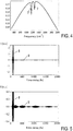
- Figures 4 and 5 show examples of a frequency domain spectrum and a time domain signal obtained with the EOS method, resp..
- a modified spectrum of the probe light pulses 2' MIR laser spectrum
- the frequency range of 500 to 2000 cm -1 wavelength range 20 ⁇ m to 5 ⁇ m
- Electro-optical sampling then generates the field of the pulse in the time domain, which is essentially the inverse Fourier Transform of the field spectrum, as shown in Figure 5A . It consists of a so-called centre-burst 8, corresponding to the broad primary spectrum of the probe light pulses, followed by a long tail 9 resulting from the narrow absorption lines 7.
- Figure 5B shows the signal with the centre-burst 8 out of scale to show features of the tail 9.
- the Fourier Transform of this signal is complex, including not only the power spectrum of the absorption lines 7 as in ordinary Fourier Transform spectroscopy, but the spectral phase as well.
- the pulse as shown is sampled over a time delay of 20 ps, which is equivalent to a spectral resolution of 1.7 cm -1 .
- the vertical scales of both diagrams are in arbitrary units.
- Figure 5 shows the background-free measurement according to the invention.
- the detection is done with zero-background, i. e. without noise caused by the probe light pulses.
- This advantage cannot be obtained with broadband synchrotron radiation, which has pulse durations in the ps-range.
- the trails of spectral bands in the temporal shape would be superimposed by the synchrotron probe light.
- the spectral response of the sample 1 can be further processed for obtaining diagnostically relevant information 6 (see Figures 1, 2 ). This further processing can be done by the calculation device 40.
- the spectral features of the absorption lines 7 can be obtained by subjecting the spectral response to a filtering process. Specific bands of compounds characteristic of the health status of a person can be identified. Furthermore, the spectral response can be compared with data previously collected with the same organism and/or with reference data collected with other, healthy or non-healthy subjects.
Claims (10)
- Procédé de mesure d'une réponse spectrale d'un échantillon (1), comprenant les étapes :- génération d'une lumière sonde ayant un spectre primaire et comprenant des impulsions de lumière sonde (2) qui sont générées avec un dispositif de source laser fs (10) et ayant une durée d'impulsion inférieure ou égale à 100 fs, dans lequel le spectre primaire couvre une plage de longueurs d'onde incluant des longueurs d'onde d'au moins 3 µm,- irradiation de l'échantillon (1) avec la lumière sonde, incluant une interaction de la lumière sonde et de l'échantillon (1), et- détection à résolution spectrale de la lumière sonde ayant un spectre modifié, qui s'écarte du spectre primaire par suite de l'interaction de la lumière sonde et de l'échantillon (1), ledit spectre modifié étant caractéristique de la réponse spectrale de l'échantillon (1), dans lequel- l'étape de détection comprend l'échantillonnage dans le domaine temporel d'une forme temporelle des impulsions de lumière sonde (2) après l'interaction avec l'échantillon (1) et la réponse spectrale de l'échantillon (1) est obtenue sur la base d'une transformation de Fourier de la forme temporelle des impulsions de lumière sonde (2) après l'interaction avec l'échantillon (1),caractérisé en ce que- l'échantillon comprend un échantillon biologique (1),- les impulsions de lumière sonde (2) sont créées avec une puissance moyenne au-delà de 50 mW, et- après l'interaction avec l'échantillon biologique (1), chacune des impulsions de lumière sonde (2) comprend une impulsion principale correspondant au spectre primaire des impulsions de lumière sonde et une traînée temporelle étant induite par absorption de l'échantillon biologique (1) et traînant l'impulsion principale, dans lequel l'échantillonnage dans le domaine temporel de la forme temporelle des impulsions de lumière sonde (2) inclut l'échantillonnage de la traînée temporelle.
- Procédé selon la revendication 1, dans lequel les impulsions de lumière sonde (2) ont au moins l'une des particularités suivantes- les impulsions de lumière sonde (2) ont une durée d'impulsion en dessous d'une largeur de fréquence inverse d'un spectre incluant des particularités de réponse spectrale apparaissant dans le spectre modifié,- les impulsions de lumière sonde (2) ont une durée d'impulsion en dessous de 50 fs, en particulier en dessous de 20 fs, avant l'irradiation de l'échantillon (1),- les impulsions de lumière sonde (2) ont une puissance moyenne au-dessus de 500 mW, avant l'irradiation de l'échantillon (1),- le spectre primaire couvre au moins une octave de fréquence, en particulier au moins deux octaves de fréquence,- le spectre primaire couvre une plage de longueurs d'onde de 5 µm à 15 µm, en particulier de 3 µm à 30 µm, et- le spectre primaire est un spectre continu ou quasi continu.
- Procédé selon l'une des revendications précédentes, dans lequel- la réponse spectrale est au moins l'un d'un spectre d'absorption et d'un spectre de réflexion de l'échantillon (1).
- Procédé selon l'une des revendications précédentes, ayant au moins l'une des particularités suivantes- l'échantillon (1) comprend au moins l'un parmi un solide, un liquide, un aérosol, un gaz et une vapeur, et- l'échantillon (1) est agencé dans une cellule multipasse ou une cavité d'accroissement.
- Procédé selon l'une des revendications précédentes, dans lequel le dispositif de source laser fs (10) inclut- une source d'entraînement (11) créant des impulsions d'entraînement, et- une unité de génération de fréquence de différence (DFG) (12) générant les impulsions de lumière sonde (2) par des différences de fréquence intraimpulsion des impulsions d'entraînement.
- Procédé selon l'une des revendications précédentes, dans lequel le dispositif de source laser fs inclut- un laser à fibre,- un laser à disque Yb-YAG, ou- un laser à disque Ho-YAG.
- Procédé selon l'une des revendications précédentes, dans lequel- l'étape d'échantillonnage dans le domaine temporel comprend l'échantillonnage électro-optique des impulsions de lumière sonde (2), dans lequel- les impulsions de lumière sonde (2) et les impulsions d'échantillonnage (5) sont superposées avec une relation temporelle variable dans un élément de sonde électro-optique (21) pour échantillonnage de la forme temporelle de la lumière sonde.
- Procédé selon la revendication 7, dans lequel- les impulsions d'échantillonnage (5) comprennent des parties d'impulsions d'entraînement (3) utilisées pour la génération des impulsions de lumière sonde (2), lesdites impulsions d'échantillonnage (5) étant dirigées vers l'élément de sonde électro-optique avec un retard variable par rapport aux impulsions de lumière sonde (2).
- Procédé selon l'une des revendications précédentes, comprenant l'étape supplémentaire- évaluation de la réponse spectrale de l'échantillon (1) à partir d'un sujet sous investigation pour obtenir une information pertinente sur le plan du diagnostic (6) qui peut être utilisée pour fournir ou valider un diagnostic médical.
- Procédé selon la revendication 9, dans lequel l'étape d'évaluation inclut au moins l'un parmi- l'identification de substances pertinentes sur le plan du diagnostic sur la base de bandes spécifiques (7) dans le spectre modifié,- la comparaison d'au moins une portion du spectre modifié avec une réponse spectrale mémorisée préalablement collectée à un autre échantillon (1) du sujet sous investigation, et- la comparaison d'au moins une portion du spectre modifié à des données de référence d'autres sujets.
Priority Applications (12)
| Application Number | Priority Date | Filing Date | Title |
|---|---|---|---|
| HUE14004401A HUE042517T2 (hu) | 2014-12-23 | 2014-12-23 | Eljárás spektrális minta válasz mérésére |
| ES14004401T ES2712200T3 (es) | 2014-12-23 | 2014-12-23 | Método para medir una respuesta de muestra espectral |
| EP14004401.7A EP3037805B1 (fr) | 2014-12-23 | 2014-12-23 | Procédé pour mesurer une réponse d'échantillon spectrale |
| EP15828483.6A EP3237883B1 (fr) | 2014-12-23 | 2015-12-18 | Appareil pour mesurer une réponse spectrale d'un échantillon biologique |
| KR1020177016687A KR102432337B1 (ko) | 2014-12-23 | 2015-12-18 | 스펙트럼 샘플 반응을 측정하기 위한 방법 및 장치 |
| HUE15828483A HUE051316T2 (hu) | 2014-12-23 | 2015-12-18 | Berendezés egy biológiai minta spektrális válaszának mérésére |
| PCT/EP2015/002562 WO2016102056A1 (fr) | 2014-12-23 | 2015-12-18 | Procédé et appareil de mesure d'une réponse spectrale d'échantillon |
| CA2969240A CA2969240C (fr) | 2014-12-23 | 2015-12-18 | Procede et appareil de mesure d'une reponse spectrale d'echantillon |
| ES15828483T ES2820301T3 (es) | 2014-12-23 | 2015-12-18 | Aparato para medir una respuesta espectral de una muestra biológica |
| JP2017534310A JP6692822B2 (ja) | 2014-12-23 | 2015-12-18 | 試料スペクトル応答を測定するための方法および装置 |
| CN201580070903.XA CN107110774B (zh) | 2014-12-23 | 2015-12-18 | 用于测量光谱样品响应的方法和仪器 |
| US15/538,018 US10101268B2 (en) | 2014-12-23 | 2015-12-18 | Method and apparatus for measuring a spectral sample response |
Applications Claiming Priority (1)
| Application Number | Priority Date | Filing Date | Title |
|---|---|---|---|
| EP14004401.7A EP3037805B1 (fr) | 2014-12-23 | 2014-12-23 | Procédé pour mesurer une réponse d'échantillon spectrale |
Publications (2)
| Publication Number | Publication Date |
|---|---|
| EP3037805A1 EP3037805A1 (fr) | 2016-06-29 |
| EP3037805B1 true EP3037805B1 (fr) | 2018-11-28 |
Family
ID=52338790
Family Applications (2)
| Application Number | Title | Priority Date | Filing Date |
|---|---|---|---|
| EP14004401.7A Active EP3037805B1 (fr) | 2014-12-23 | 2014-12-23 | Procédé pour mesurer une réponse d'échantillon spectrale |
| EP15828483.6A Active EP3237883B1 (fr) | 2014-12-23 | 2015-12-18 | Appareil pour mesurer une réponse spectrale d'un échantillon biologique |
Family Applications After (1)
| Application Number | Title | Priority Date | Filing Date |
|---|---|---|---|
| EP15828483.6A Active EP3237883B1 (fr) | 2014-12-23 | 2015-12-18 | Appareil pour mesurer une réponse spectrale d'un échantillon biologique |
Country Status (9)
| Country | Link |
|---|---|
| US (1) | US10101268B2 (fr) |
| EP (2) | EP3037805B1 (fr) |
| JP (1) | JP6692822B2 (fr) |
| KR (1) | KR102432337B1 (fr) |
| CN (1) | CN107110774B (fr) |
| CA (1) | CA2969240C (fr) |
| ES (2) | ES2712200T3 (fr) |
| HU (2) | HUE042517T2 (fr) |
| WO (1) | WO2016102056A1 (fr) |
Families Citing this family (21)
| Publication number | Priority date | Publication date | Assignee | Title |
|---|---|---|---|---|
| US10925515B2 (en) | 2014-05-22 | 2021-02-23 | Picomole Inc. | Alveolar breath collection apparatus |
| CN109313119B (zh) * | 2016-06-20 | 2021-11-02 | 普莱尔股份公司 | 用于检测和/或表征流体携带的颗粒的装置和方法 |
| US10666012B2 (en) | 2017-03-13 | 2020-05-26 | Picomole Inc. | Apparatus and method of optimizing laser system |
| CA3054470C (fr) * | 2017-03-21 | 2023-10-03 | Max-Planck-Gesellschaft Zur Forderung Der Wissenschaften E.V. | Procedes et dispositifs de mesure de changements de la reponse de polarisation d'un echantillon par spectroscopie infrarouge a domaine temporel (spectroscopie vibrationnelle a res olution de champ) |
| US10948418B2 (en) | 2017-05-19 | 2021-03-16 | National Research Council Of Canada | Characterization of a material using combined laser-based IR spectroscopy and laser-induced breakdown spectroscopy |
| DE102017219338B3 (de) * | 2017-10-27 | 2019-02-28 | Humboldt-Universität Zu Berlin | Photoakustik-Sensorkopf und Photoakustik-Messapparat mit verbesserter Störsignal-Unterdrückung |
| KR102119714B1 (ko) | 2017-11-28 | 2020-06-16 | 주식회사 셀투인 | 실시간 글루타치온 측정을 통한 치료용 세포의 품질 향상 방법 |
| CN108195761B (zh) * | 2018-03-06 | 2023-08-11 | 南京信息工程大学 | 一种多维可调的分子准直实验系统 |
| US11226534B2 (en) * | 2018-08-21 | 2022-01-18 | Fathom Radiant, PBC | Methods and apparatus for generating mid-infrared frequency combs |
| CN112703386A (zh) * | 2018-09-14 | 2021-04-23 | 马克思-普朗克科学促进协会 | 用于基于光谱测定粒子分析的粒子分析方法和设备 |
| US11035789B2 (en) | 2019-04-03 | 2021-06-15 | Picomole Inc. | Cavity ring-down spectroscopy system and method of modulating a light beam therein |
| KR102158203B1 (ko) * | 2019-10-24 | 2020-09-22 | 울산과학기술원 | 헤테로다인 방식의 이차원 적외선 분광장치 및 이를 이용한 분광방법 |
| US11957450B2 (en) | 2020-02-28 | 2024-04-16 | Picomole Inc. | Apparatus and method for collecting a breath sample using an air circulation system |
| US11782049B2 (en) | 2020-02-28 | 2023-10-10 | Picomole Inc. | Apparatus and method for collecting a breath sample using a container with controllable volume |
| CN111368801A (zh) * | 2020-03-27 | 2020-07-03 | 吉林求是光谱数据科技有限公司 | 真假指纹识别装置及其识别方法 |
| CA3216742A1 (fr) * | 2020-05-19 | 2021-11-25 | Alfred W. League | Systemes de detection et leurs procedes d'utilisation |
| CN112525847B (zh) * | 2020-12-03 | 2022-12-30 | 中国科学院上海技术物理研究所 | 一种宽温区可凝挥发物实时光谱测试装置和测试方法 |
| EP4068532A1 (fr) | 2021-03-31 | 2022-10-05 | Max-Planck-Gesellschaft zur Förderung der Wissenschaften e.V. | Procédé et appareil d'amélioration d'impulsions laser pour améliorer par résonance la lumière laser pulsée pour des applications pratiques et des mesures sensibles |
| EP4348224A1 (fr) * | 2021-05-27 | 2024-04-10 | Molekuláris- Ujjlenyomat Kutató Központ Nonprofit Kft. | Appareil et procédé de mesure d'une réponse spectrale d'un échantillon, comprenant une amplification de la lumière basée sur un laser à cascade quantique |
| WO2022271079A1 (fr) * | 2021-06-21 | 2022-12-29 | Anor Technologies Pte. Ltd. | Système de spectroscopie térahertz |
| CN117589687B (zh) * | 2024-01-18 | 2024-04-09 | 成都艾立本科技有限公司 | 基于空气包裹液体的光学腔容器及用途及光谱检测方法 |
Family Cites Families (34)
| Publication number | Priority date | Publication date | Assignee | Title |
|---|---|---|---|---|
| US5222495A (en) | 1990-02-02 | 1993-06-29 | Angiomedics Ii, Inc. | Non-invasive blood analysis by near infrared absorption measurements using two closely spaced wavelengths |
| US5467767A (en) * | 1991-11-25 | 1995-11-21 | Alfano; Robert R. | Method for determining if tissue is malignant as opposed to non-malignant using time-resolved fluorescence spectroscopy |
| US5438985A (en) | 1993-01-25 | 1995-08-08 | Synectics Medical, Incorporated | Ambulatory recording of the presence and activity of substances in gastro-intestinal compartments |
| US6040578A (en) | 1996-02-02 | 2000-03-21 | Instrumentation Metrics, Inc. | Method and apparatus for multi-spectral analysis of organic blood analytes in noninvasive infrared spectroscopy |
| US6544193B2 (en) | 1996-09-04 | 2003-04-08 | Marcio Marc Abreu | Noninvasive measurement of chemical substances |
| US6628809B1 (en) | 1999-10-08 | 2003-09-30 | Lumidigm, Inc. | Apparatus and method for identification of individuals by near-infrared spectrum |
| US5999259A (en) * | 1998-10-02 | 1999-12-07 | Innovative Lasers Corporation | Contaminant identification and concentration determination by monitoring the wavelength, or intensity at a specific wavelength, of the output of an intracavity laser |
| JP4091193B2 (ja) | 1999-01-27 | 2008-05-28 | 浜松ホトニクス株式会社 | 媒質の非線形光学応答測定装置 |
| DE60203502T2 (de) * | 2001-06-23 | 2005-09-08 | Thomson Licensing S.A. | Anzeigetafel mit farbfehlern in folge unterschiedlicher leuchtstoff- antwortzeiten |
| US7606274B2 (en) * | 2001-09-20 | 2009-10-20 | The Uab Research Foundation | Mid-IR instrument for analyzing a gaseous sample and method for using the same |
| US7101340B1 (en) | 2002-04-12 | 2006-09-05 | Braun Charles L | Spectroscopic breath profile analysis device and uses thereof for facilitating diagnosis of medical conditions |
| CN1614391A (zh) * | 2003-11-03 | 2005-05-11 | 中国科学院上海应用物理研究所 | 中草药真伪及质量鉴别的快速无损分析方法 |
| US8903474B2 (en) | 2005-12-06 | 2014-12-02 | Pen Inc. | Analysis of gases |
| WO2007121598A1 (fr) * | 2006-04-21 | 2007-11-01 | Eth Zurich | Systeme et procede de generation et de detection d'un rayonnement a large bande de l'ordre du terahertz |
| US7973927B2 (en) * | 2006-09-29 | 2011-07-05 | Uwm Research Foundation, Inc. | Two-photon microscope with spectral resolution |
| JP5035618B2 (ja) * | 2006-12-05 | 2012-09-26 | 独立行政法人理化学研究所 | 電磁波を用いた検出方法、及び検出装置 |
| US8022366B2 (en) | 2007-06-11 | 2011-09-20 | Frank Hartley | Non-invasive qualitative measurement of chemistry of blood and bodily fluids |
| CA2731301A1 (fr) * | 2008-07-25 | 2010-01-28 | Centre National De La Recherche Scientifique (Cnrs) | Spectrometre a transformee de fourier dote d'une source de lumiere en peigne de frequences |
| CN101561425B (zh) * | 2009-06-02 | 2012-03-14 | 福州大学 | 加压毛细管电色谱电致化学发光检测装置 |
| JP5256136B2 (ja) * | 2009-07-09 | 2013-08-07 | 三井造船株式会社 | 電磁波測定装置、及び電磁波測定方法 |
| JP2011149698A (ja) | 2009-12-25 | 2011-08-04 | National Institute Of Information & Communication Technology | テラヘルツ波帯用の窓部材、試料容器、検出発生装置、基板材料、並びに、単結晶シリコンカーバイドの透過特性の算出方法及び評価方法 |
| WO2011091316A2 (fr) * | 2010-01-22 | 2011-07-28 | Newport Corporation | Oscillateur paramétrique optique largement accordable |
| CN101826910B (zh) * | 2010-03-23 | 2013-11-27 | 上海师范大学 | 一种成对载波复用多用户随机接入中的信号参数提取方法 |
| WO2011117572A1 (fr) | 2010-03-25 | 2011-09-29 | Isis Innovation Limited | Analyse de la respiration |
| JP5445775B2 (ja) * | 2010-05-16 | 2014-03-19 | 大塚電子株式会社 | 超高分解テラヘルツ分光計測装置 |
| JP2011252736A (ja) * | 2010-05-31 | 2011-12-15 | Taiheiyo Cement Corp | セメント硬化体の体積含水率測定方法 |
| JP5710935B2 (ja) * | 2010-10-26 | 2015-04-30 | ソニー株式会社 | 半導体光増幅器組立体 |
| JP5578120B2 (ja) * | 2011-03-16 | 2014-08-27 | 住友金属鉱山株式会社 | 二層めっき基板の密着性評価方法 |
| CN102175636B (zh) * | 2011-03-18 | 2012-12-26 | 上海理工大学 | 一种中草药检测鉴别的系统和方法 |
| US9222881B2 (en) * | 2012-02-24 | 2015-12-29 | Massachusetts Institute Of Technology | Vibrational spectroscopy for quantitative measurement of analytes |
| JP5892597B2 (ja) * | 2012-02-24 | 2016-03-23 | 株式会社Screenホールディングス | 検査装置および検査方法 |
| US9250128B2 (en) | 2012-03-02 | 2016-02-02 | Beihang University | Method and apparatus for optical asynchronous sampling signal measurements |
| JP5510851B2 (ja) * | 2012-12-28 | 2014-06-04 | 独立行政法人日本原子力研究開発機構 | テラヘルツ測定法 |
| CN103389287B (zh) * | 2013-07-17 | 2015-08-12 | 福建师范大学 | 一种适用于活体肝表面成像的高分辨光学系统 |
-
2014
- 2014-12-23 EP EP14004401.7A patent/EP3037805B1/fr active Active
- 2014-12-23 HU HUE14004401A patent/HUE042517T2/hu unknown
- 2014-12-23 ES ES14004401T patent/ES2712200T3/es active Active
-
2015
- 2015-12-18 EP EP15828483.6A patent/EP3237883B1/fr active Active
- 2015-12-18 HU HUE15828483A patent/HUE051316T2/hu unknown
- 2015-12-18 CN CN201580070903.XA patent/CN107110774B/zh active Active
- 2015-12-18 ES ES15828483T patent/ES2820301T3/es active Active
- 2015-12-18 US US15/538,018 patent/US10101268B2/en active Active
- 2015-12-18 CA CA2969240A patent/CA2969240C/fr active Active
- 2015-12-18 JP JP2017534310A patent/JP6692822B2/ja active Active
- 2015-12-18 KR KR1020177016687A patent/KR102432337B1/ko active IP Right Grant
- 2015-12-18 WO PCT/EP2015/002562 patent/WO2016102056A1/fr active Application Filing
Non-Patent Citations (4)
| Title |
|---|
| ALBERT SCHLIESSER ET AL: "Mid-infrared frequency combs", NATURE PHOTONICS, 28 June 2012 (2012-06-28), London, pages 440 - 449, XP055320174, Retrieved from the Internet <URL:https://arxiv.org/ftp/arxiv/papers/1205/1205.3395.pdf> [retrieved on 20161116], DOI: 10.1038/nphoton.2012.142 * |
| HANIEH FATTAHI ET AL: "Efficient, octave-spanning difference-frequency generation using few-cycle pulses in simple collinear geometry", OPTICS LETTERS, OPTICAL SOCIETY OF AMERICA, vol. 38, no. 20, 15 October 2013 (2013-10-15), pages 4216 - 4219, XP001584940, ISSN: 0146-9592, [retrieved on 20131014], DOI: 10.1364/OL.38.004216 * |
| PUPEZA I ET AL: "Compact 0.1-W source of octave-spanning mid-infrared femtosecond pulses centered at 10 [mu]m", 2014 CONFERENCE ON LASERS AND ELECTRO-OPTICS (CLEO) - LASER SCIENCE TO PHOTONIC APPLICATIONS, THE OPTICAL SOCIETY, June 2014 (2014-06-01), San Jose, CA, USA, pages 1 - 2, XP032708486 * |
| SELL A ET AL: "Phase-locked generation and field-resolved detection of widely tunable terahertz pulses with amplitudes exceeding 100 MV/cm", OPTICS LETTERS, OPTICAL SOCIETY OF AMERICA, vol. 33, no. 23, 1 December 2008 (2008-12-01), pages 2767 - 2769, XP001520998, ISSN: 0146-9592, DOI: 10.1364/OL.33.002767 * |
Also Published As
| Publication number | Publication date |
|---|---|
| EP3237883B1 (fr) | 2020-08-05 |
| EP3037805A1 (fr) | 2016-06-29 |
| ES2820301T3 (es) | 2021-04-20 |
| CA2969240C (fr) | 2021-11-23 |
| ES2712200T3 (es) | 2019-05-09 |
| EP3237883A1 (fr) | 2017-11-01 |
| WO2016102056A1 (fr) | 2016-06-30 |
| WO2016102056A9 (fr) | 2016-09-01 |
| JP6692822B2 (ja) | 2020-05-13 |
| KR20170107429A (ko) | 2017-09-25 |
| US20180003623A1 (en) | 2018-01-04 |
| JP2018500568A (ja) | 2018-01-11 |
| KR102432337B1 (ko) | 2022-08-12 |
| CN107110774B (zh) | 2020-07-28 |
| HUE051316T2 (hu) | 2021-03-01 |
| CA2969240A1 (fr) | 2016-06-30 |
| CN107110774A (zh) | 2017-08-29 |
| HUE042517T2 (hu) | 2019-07-29 |
| US10101268B2 (en) | 2018-10-16 |
Similar Documents
| Publication | Publication Date | Title |
|---|---|---|
| EP3037805B1 (fr) | Procédé pour mesurer une réponse d'échantillon spectrale | |
| Matousek et al. | Subsurface probing in diffusely scattering media using spatially offset Raman spectroscopy | |
| US6064897A (en) | Sensor utilizing Raman spectroscopy for non-invasive monitoring of analytes in biological fluid and method of use | |
| TW541417B (en) | Dual beam FTIR methods and devices for use in analyte detection in samples of low transmissivity | |
| JP3715241B2 (ja) | ラマン分光検査法を使用して体液中の物質を検出する方法および装置 | |
| Lieber et al. | Automated method for subtraction of fluorescence from biological Raman spectra | |
| CN104958075B (zh) | 使用拉曼光谱非侵入性测量皮肤厚度和血糖浓度及其校准方法 | |
| US7330746B2 (en) | Non-invasive biochemical analysis | |
| Butler et al. | Shining a light on clinical spectroscopy: Translation of diagnostic IR, 2D-IR and Raman spectroscopy towards the clinic | |
| EP1715327A2 (fr) | Dispositif de mesure à infrarouge, connu en particulier pour la spectrométrie de systèmes aqueux, de préférence de systémes à composants multiples | |
| JP2003508745A (ja) | 近赤外、隣接可視スペクトルおよびより長い近赤外波長のアレイを使用する被分析対象の判定方法 | |
| US20060176478A1 (en) | Raman spectroscopy with stabilized multi-mode lasers | |
| Ghazaryan et al. | Extended near-infrared optoacoustic spectrometry for sensing physiological concentrations of glucose | |
| US8344323B1 (en) | Apparatus and method for detecting and quantifying analytes in solution | |
| Huber et al. | Optimum sample thickness for trace analyte detection with field-resolved infrared spectroscopy | |
| Oh et al. | The high-quality spectral fingerprint of glucose captured by Raman spectroscopy in non-invasive glucose measurement | |
| EP3850335B1 (fr) | Procédé et appareil d'analyse de particules pour une analyse de particules basée sur la spectrométrie | |
| Saade et al. | Glicemical analysis of human blood serum using FT-Raman: a new approach | |
| JP4028541B2 (ja) | サンプルの化学成分を分析する分析システムおよびその分析方法 | |
| Sun | Comparison and combination of near-infrared and Raman spectra for PLS and NAS quantitation of glucose, urea and lactate | |
| Qu et al. | Screening of therapeutical drugs and substances of abuse in human body fluids by near-IR laser Raman spectroscopy | |
| Brandstetter et al. | External Cavity Quantum Cascade Lasers for Measurements in Liquids |
Legal Events
| Date | Code | Title | Description |
|---|---|---|---|
| PUAI | Public reference made under article 153(3) epc to a published international application that has entered the european phase |
Free format text: ORIGINAL CODE: 0009012 |
|
| AK | Designated contracting states |
Kind code of ref document: A1 Designated state(s): AL AT BE BG CH CY CZ DE DK EE ES FI FR GB GR HR HU IE IS IT LI LT LU LV MC MK MT NL NO PL PT RO RS SE SI SK SM TR |
|
| AX | Request for extension of the european patent |
Extension state: BA ME |
|
| STAA | Information on the status of an ep patent application or granted ep patent |
Free format text: STATUS: REQUEST FOR EXAMINATION WAS MADE |
|
| 17P | Request for examination filed |
Effective date: 20161223 |
|
| RBV | Designated contracting states (corrected) |
Designated state(s): AL AT BE BG CH CY CZ DE DK EE ES FI FR GB GR HR HU IE IS IT LI LT LU LV MC MK MT NL NO PL PT RO RS SE SI SK SM TR |
|
| STAA | Information on the status of an ep patent application or granted ep patent |
Free format text: STATUS: EXAMINATION IS IN PROGRESS |
|
| 17Q | First examination report despatched |
Effective date: 20171011 |
|
| GRAP | Despatch of communication of intention to grant a patent |
Free format text: ORIGINAL CODE: EPIDOSNIGR1 |
|
| STAA | Information on the status of an ep patent application or granted ep patent |
Free format text: STATUS: GRANT OF PATENT IS INTENDED |
|
| RIC1 | Information provided on ipc code assigned before grant |
Ipc: G01N 21/3586 20140101ALN20180424BHEP Ipc: G01N 21/3563 20140101ALN20180424BHEP Ipc: H01S 3/00 20060101ALN20180424BHEP Ipc: G01N 21/35 20140101AFI20180424BHEP Ipc: G01N 21/03 20060101ALN20180424BHEP Ipc: G01N 21/3577 20140101ALN20180424BHEP Ipc: G01N 21/3504 20140101ALN20180424BHEP |
|
| INTG | Intention to grant announced |
Effective date: 20180516 |
|
| GRAJ | Information related to disapproval of communication of intention to grant by the applicant or resumption of examination proceedings by the epo deleted |
Free format text: ORIGINAL CODE: EPIDOSDIGR1 |
|
| GRAL | Information related to payment of fee for publishing/printing deleted |
Free format text: ORIGINAL CODE: EPIDOSDIGR3 |
|
| GRAS | Grant fee paid |
Free format text: ORIGINAL CODE: EPIDOSNIGR3 |
|
| STAA | Information on the status of an ep patent application or granted ep patent |
Free format text: STATUS: EXAMINATION IS IN PROGRESS |
|
| GRAR | Information related to intention to grant a patent recorded |
Free format text: ORIGINAL CODE: EPIDOSNIGR71 |
|
| STAA | Information on the status of an ep patent application or granted ep patent |
Free format text: STATUS: GRANT OF PATENT IS INTENDED |
|
| INTC | Intention to grant announced (deleted) | ||
| RIC1 | Information provided on ipc code assigned before grant |
Ipc: H01S 3/00 20060101ALN20180919BHEP Ipc: G01N 21/35 20140101AFI20180919BHEP Ipc: G01N 21/3504 20140101ALN20180919BHEP Ipc: G01N 21/03 20060101ALN20180919BHEP Ipc: G01N 21/3586 20140101ALN20180919BHEP Ipc: G01N 21/3577 20140101ALN20180919BHEP Ipc: G01N 21/3563 20140101ALN20180919BHEP |
|
| GRAA | (expected) grant |
Free format text: ORIGINAL CODE: 0009210 |
|
| STAA | Information on the status of an ep patent application or granted ep patent |
Free format text: STATUS: THE PATENT HAS BEEN GRANTED |
|
| INTG | Intention to grant announced |
Effective date: 20181018 |
|
| AK | Designated contracting states |
Kind code of ref document: B1 Designated state(s): AL AT BE BG CH CY CZ DE DK EE ES FI FR GB GR HR HU IE IS IT LI LT LU LV MC MK MT NL NO PL PT RO RS SE SI SK SM TR |
|
| REG | Reference to a national code |
Ref country code: CH Ref legal event code: EP |
|
| REG | Reference to a national code |
Ref country code: AT Ref legal event code: REF Ref document number: 1070806 Country of ref document: AT Kind code of ref document: T Effective date: 20181215 |
|
| REG | Reference to a national code |
Ref country code: DE Ref legal event code: R096 Ref document number: 602014036773 Country of ref document: DE |
|
| REG | Reference to a national code |
Ref country code: IE Ref legal event code: FG4D |
|
| REG | Reference to a national code |
Ref country code: CH Ref legal event code: NV Representative=s name: KASCHE AND PARTNER AG, CH |
|
| REG | Reference to a national code |
Ref country code: NL Ref legal event code: FP |
|
| REG | Reference to a national code |
Ref country code: LT Ref legal event code: MG4D |
|
| PG25 | Lapsed in a contracting state [announced via postgrant information from national office to epo] |
Ref country code: NO Free format text: LAPSE BECAUSE OF FAILURE TO SUBMIT A TRANSLATION OF THE DESCRIPTION OR TO PAY THE FEE WITHIN THE PRESCRIBED TIME-LIMIT Effective date: 20190228 Ref country code: LV Free format text: LAPSE BECAUSE OF FAILURE TO SUBMIT A TRANSLATION OF THE DESCRIPTION OR TO PAY THE FEE WITHIN THE PRESCRIBED TIME-LIMIT Effective date: 20181128 Ref country code: LT Free format text: LAPSE BECAUSE OF FAILURE TO SUBMIT A TRANSLATION OF THE DESCRIPTION OR TO PAY THE FEE WITHIN THE PRESCRIBED TIME-LIMIT Effective date: 20181128 Ref country code: BG Free format text: LAPSE BECAUSE OF FAILURE TO SUBMIT A TRANSLATION OF THE DESCRIPTION OR TO PAY THE FEE WITHIN THE PRESCRIBED TIME-LIMIT Effective date: 20190228 Ref country code: HR Free format text: LAPSE BECAUSE OF FAILURE TO SUBMIT A TRANSLATION OF THE DESCRIPTION OR TO PAY THE FEE WITHIN THE PRESCRIBED TIME-LIMIT Effective date: 20181128 Ref country code: FI Free format text: LAPSE BECAUSE OF FAILURE TO SUBMIT A TRANSLATION OF THE DESCRIPTION OR TO PAY THE FEE WITHIN THE PRESCRIBED TIME-LIMIT Effective date: 20181128 Ref country code: IS Free format text: LAPSE BECAUSE OF FAILURE TO SUBMIT A TRANSLATION OF THE DESCRIPTION OR TO PAY THE FEE WITHIN THE PRESCRIBED TIME-LIMIT Effective date: 20190328 |
|
| REG | Reference to a national code |
Ref country code: ES Ref legal event code: FG2A Ref document number: 2712200 Country of ref document: ES Kind code of ref document: T3 Effective date: 20190509 |
|
| PG25 | Lapsed in a contracting state [announced via postgrant information from national office to epo] |
Ref country code: GR Free format text: LAPSE BECAUSE OF FAILURE TO SUBMIT A TRANSLATION OF THE DESCRIPTION OR TO PAY THE FEE WITHIN THE PRESCRIBED TIME-LIMIT Effective date: 20190301 Ref country code: RS Free format text: LAPSE BECAUSE OF FAILURE TO SUBMIT A TRANSLATION OF THE DESCRIPTION OR TO PAY THE FEE WITHIN THE PRESCRIBED TIME-LIMIT Effective date: 20181128 Ref country code: AL Free format text: LAPSE BECAUSE OF FAILURE TO SUBMIT A TRANSLATION OF THE DESCRIPTION OR TO PAY THE FEE WITHIN THE PRESCRIBED TIME-LIMIT Effective date: 20181128 Ref country code: PT Free format text: LAPSE BECAUSE OF FAILURE TO SUBMIT A TRANSLATION OF THE DESCRIPTION OR TO PAY THE FEE WITHIN THE PRESCRIBED TIME-LIMIT Effective date: 20190328 Ref country code: SE Free format text: LAPSE BECAUSE OF FAILURE TO SUBMIT A TRANSLATION OF THE DESCRIPTION OR TO PAY THE FEE WITHIN THE PRESCRIBED TIME-LIMIT Effective date: 20181128 |
|
| REG | Reference to a national code |
Ref country code: HU Ref legal event code: AG4A Ref document number: E042517 Country of ref document: HU |
|
| PG25 | Lapsed in a contracting state [announced via postgrant information from national office to epo] |
Ref country code: PL Free format text: LAPSE BECAUSE OF FAILURE TO SUBMIT A TRANSLATION OF THE DESCRIPTION OR TO PAY THE FEE WITHIN THE PRESCRIBED TIME-LIMIT Effective date: 20181128 Ref country code: DK Free format text: LAPSE BECAUSE OF FAILURE TO SUBMIT A TRANSLATION OF THE DESCRIPTION OR TO PAY THE FEE WITHIN THE PRESCRIBED TIME-LIMIT Effective date: 20181128 Ref country code: CZ Free format text: LAPSE BECAUSE OF FAILURE TO SUBMIT A TRANSLATION OF THE DESCRIPTION OR TO PAY THE FEE WITHIN THE PRESCRIBED TIME-LIMIT Effective date: 20181128 |
|
| REG | Reference to a national code |
Ref country code: DE Ref legal event code: R097 Ref document number: 602014036773 Country of ref document: DE |
|
| PG25 | Lapsed in a contracting state [announced via postgrant information from national office to epo] |
Ref country code: SK Free format text: LAPSE BECAUSE OF FAILURE TO SUBMIT A TRANSLATION OF THE DESCRIPTION OR TO PAY THE FEE WITHIN THE PRESCRIBED TIME-LIMIT Effective date: 20181128 Ref country code: MC Free format text: LAPSE BECAUSE OF FAILURE TO SUBMIT A TRANSLATION OF THE DESCRIPTION OR TO PAY THE FEE WITHIN THE PRESCRIBED TIME-LIMIT Effective date: 20181128 Ref country code: SM Free format text: LAPSE BECAUSE OF FAILURE TO SUBMIT A TRANSLATION OF THE DESCRIPTION OR TO PAY THE FEE WITHIN THE PRESCRIBED TIME-LIMIT Effective date: 20181128 Ref country code: EE Free format text: LAPSE BECAUSE OF FAILURE TO SUBMIT A TRANSLATION OF THE DESCRIPTION OR TO PAY THE FEE WITHIN THE PRESCRIBED TIME-LIMIT Effective date: 20181128 Ref country code: LU Free format text: LAPSE BECAUSE OF NON-PAYMENT OF DUE FEES Effective date: 20181223 Ref country code: RO Free format text: LAPSE BECAUSE OF FAILURE TO SUBMIT A TRANSLATION OF THE DESCRIPTION OR TO PAY THE FEE WITHIN THE PRESCRIBED TIME-LIMIT Effective date: 20181128 |
|
| REG | Reference to a national code |
Ref country code: IE Ref legal event code: MM4A |
|
| REG | Reference to a national code |
Ref country code: BE Ref legal event code: MM Effective date: 20181231 |
|
| PLBE | No opposition filed within time limit |
Free format text: ORIGINAL CODE: 0009261 |
|
| STAA | Information on the status of an ep patent application or granted ep patent |
Free format text: STATUS: NO OPPOSITION FILED WITHIN TIME LIMIT |
|
| PG25 | Lapsed in a contracting state [announced via postgrant information from national office to epo] |
Ref country code: SI Free format text: LAPSE BECAUSE OF FAILURE TO SUBMIT A TRANSLATION OF THE DESCRIPTION OR TO PAY THE FEE WITHIN THE PRESCRIBED TIME-LIMIT Effective date: 20181128 Ref country code: IE Free format text: LAPSE BECAUSE OF NON-PAYMENT OF DUE FEES Effective date: 20181223 |
|
| 26N | No opposition filed |
Effective date: 20190829 |
|
| PG25 | Lapsed in a contracting state [announced via postgrant information from national office to epo] |
Ref country code: BE Free format text: LAPSE BECAUSE OF NON-PAYMENT OF DUE FEES Effective date: 20181231 |
|
| PG25 | Lapsed in a contracting state [announced via postgrant information from national office to epo] |
Ref country code: MT Free format text: LAPSE BECAUSE OF NON-PAYMENT OF DUE FEES Effective date: 20181223 |
|
| PG25 | Lapsed in a contracting state [announced via postgrant information from national office to epo] |
Ref country code: TR Free format text: LAPSE BECAUSE OF FAILURE TO SUBMIT A TRANSLATION OF THE DESCRIPTION OR TO PAY THE FEE WITHIN THE PRESCRIBED TIME-LIMIT Effective date: 20181128 |
|
| PG25 | Lapsed in a contracting state [announced via postgrant information from national office to epo] |
Ref country code: MK Free format text: LAPSE BECAUSE OF NON-PAYMENT OF DUE FEES Effective date: 20181128 Ref country code: CY Free format text: LAPSE BECAUSE OF FAILURE TO SUBMIT A TRANSLATION OF THE DESCRIPTION OR TO PAY THE FEE WITHIN THE PRESCRIBED TIME-LIMIT Effective date: 20181128 |
|
| REG | Reference to a national code |
Ref country code: AT Ref legal event code: UEP Ref document number: 1070806 Country of ref document: AT Kind code of ref document: T Effective date: 20181128 |
|
| PGFP | Annual fee paid to national office [announced via postgrant information from national office to epo] |
Ref country code: ES Payment date: 20230119 Year of fee payment: 9 Ref country code: CH Payment date: 20230103 Year of fee payment: 9 |
|
| PGFP | Annual fee paid to national office [announced via postgrant information from national office to epo] |
Ref country code: IT Payment date: 20221230 Year of fee payment: 9 |
|
| PGFP | Annual fee paid to national office [announced via postgrant information from national office to epo] |
Ref country code: GB Payment date: 20231220 Year of fee payment: 10 |
|
| PGFP | Annual fee paid to national office [announced via postgrant information from national office to epo] |
Ref country code: NL Payment date: 20231219 Year of fee payment: 10 Ref country code: HU Payment date: 20231215 Year of fee payment: 10 Ref country code: FR Payment date: 20231219 Year of fee payment: 10 Ref country code: DE Payment date: 20231129 Year of fee payment: 10 Ref country code: AT Payment date: 20231214 Year of fee payment: 10 |
|
| PGFP | Annual fee paid to national office [announced via postgrant information from national office to epo] |
Ref country code: ES Payment date: 20240118 Year of fee payment: 10 |