EP3619773B2 - Anschlussklemme - Google Patents
Anschlussklemme Download PDFInfo
- Publication number
- EP3619773B2 EP3619773B2 EP18721327.7A EP18721327A EP3619773B2 EP 3619773 B2 EP3619773 B2 EP 3619773B2 EP 18721327 A EP18721327 A EP 18721327A EP 3619773 B2 EP3619773 B2 EP 3619773B2
- Authority
- EP
- European Patent Office
- Prior art keywords
- actuating
- channel
- clamping
- leg
- conductor
- Prior art date
- Legal status (The legal status is an assumption and is not a legal conclusion. Google has not performed a legal analysis and makes no representation as to the accuracy of the status listed.)
- Active
Links
Images


Classifications
-
- H—ELECTRICITY
- H01—ELECTRIC ELEMENTS
- H01R—ELECTRICALLY-CONDUCTIVE CONNECTIONS; STRUCTURAL ASSOCIATIONS OF A PLURALITY OF MUTUALLY-INSULATED ELECTRICAL CONNECTING ELEMENTS; COUPLING DEVICES; CURRENT COLLECTORS
- H01R4/00—Electrically-conductive connections between two or more conductive members in direct contact, i.e. touching one another; Means for effecting or maintaining such contact; Electrically-conductive connections having two or more spaced connecting locations for conductors and using contact members penetrating insulation
- H01R4/28—Clamped connections, spring connections
- H01R4/48—Clamped connections, spring connections utilising a spring, clip, or other resilient member
- H01R4/489—Clamped connections, spring connections utilising a spring, clip, or other resilient member spring force increased by screw, cam, wedge, or other fastening means
-
- H—ELECTRICITY
- H01—ELECTRIC ELEMENTS
- H01R—ELECTRICALLY-CONDUCTIVE CONNECTIONS; STRUCTURAL ASSOCIATIONS OF A PLURALITY OF MUTUALLY-INSULATED ELECTRICAL CONNECTING ELEMENTS; COUPLING DEVICES; CURRENT COLLECTORS
- H01R4/00—Electrically-conductive connections between two or more conductive members in direct contact, i.e. touching one another; Means for effecting or maintaining such contact; Electrically-conductive connections having two or more spaced connecting locations for conductors and using contact members penetrating insulation
- H01R4/28—Clamped connections, spring connections
- H01R4/48—Clamped connections, spring connections utilising a spring, clip, or other resilient member
- H01R4/4809—Clamped connections, spring connections utilising a spring, clip, or other resilient member using a leaf spring to bias the conductor toward the busbar
- H01R4/48185—Clamped connections, spring connections utilising a spring, clip, or other resilient member using a leaf spring to bias the conductor toward the busbar adapted for axial insertion of a wire end
- H01R4/4819—Clamped connections, spring connections utilising a spring, clip, or other resilient member using a leaf spring to bias the conductor toward the busbar adapted for axial insertion of a wire end the spring shape allowing insertion of the conductor end when the spring is unbiased
- H01R4/4821—Single-blade spring
-
- H—ELECTRICITY
- H01—ELECTRIC ELEMENTS
- H01R—ELECTRICALLY-CONDUCTIVE CONNECTIONS; STRUCTURAL ASSOCIATIONS OF A PLURALITY OF MUTUALLY-INSULATED ELECTRICAL CONNECTING ELEMENTS; COUPLING DEVICES; CURRENT COLLECTORS
- H01R4/00—Electrically-conductive connections between two or more conductive members in direct contact, i.e. touching one another; Means for effecting or maintaining such contact; Electrically-conductive connections having two or more spaced connecting locations for conductors and using contact members penetrating insulation
- H01R4/28—Clamped connections, spring connections
- H01R4/48—Clamped connections, spring connections utilising a spring, clip, or other resilient member
- H01R4/4809—Clamped connections, spring connections utilising a spring, clip, or other resilient member using a leaf spring to bias the conductor toward the busbar
- H01R4/4828—Spring-activating arrangements mounted on or integrally formed with the spring housing
- H01R4/4833—Sliding arrangements, e.g. sliding button
-
- H—ELECTRICITY
- H01—ELECTRIC ELEMENTS
- H01R—ELECTRICALLY-CONDUCTIVE CONNECTIONS; STRUCTURAL ASSOCIATIONS OF A PLURALITY OF MUTUALLY-INSULATED ELECTRICAL CONNECTING ELEMENTS; COUPLING DEVICES; CURRENT COLLECTORS
- H01R9/00—Structural associations of a plurality of mutually-insulated electrical connecting elements, e.g. terminal strips or terminal blocks; Terminals or binding posts mounted upon a base or in a case; Bases therefor
- H01R9/22—Bases, e.g. strip, block, panel
- H01R9/223—Insulating enclosures for terminals
-
- H—ELECTRICITY
- H01—ELECTRIC ELEMENTS
- H01R—ELECTRICALLY-CONDUCTIVE CONNECTIONS; STRUCTURAL ASSOCIATIONS OF A PLURALITY OF MUTUALLY-INSULATED ELECTRICAL CONNECTING ELEMENTS; COUPLING DEVICES; CURRENT COLLECTORS
- H01R9/00—Structural associations of a plurality of mutually-insulated electrical connecting elements, e.g. terminal strips or terminal blocks; Terminals or binding posts mounted upon a base or in a case; Bases therefor
- H01R9/22—Bases, e.g. strip, block, panel
- H01R9/24—Terminal blocks
- H01R9/2408—Modular blocks
-
- H—ELECTRICITY
- H01—ELECTRIC ELEMENTS
- H01R—ELECTRICALLY-CONDUCTIVE CONNECTIONS; STRUCTURAL ASSOCIATIONS OF A PLURALITY OF MUTUALLY-INSULATED ELECTRICAL CONNECTING ELEMENTS; COUPLING DEVICES; CURRENT COLLECTORS
- H01R4/00—Electrically-conductive connections between two or more conductive members in direct contact, i.e. touching one another; Means for effecting or maintaining such contact; Electrically-conductive connections having two or more spaced connecting locations for conductors and using contact members penetrating insulation
- H01R4/28—Clamped connections, spring connections
- H01R4/48—Clamped connections, spring connections utilising a spring, clip, or other resilient member
- H01R4/4809—Clamped connections, spring connections utilising a spring, clip, or other resilient member using a leaf spring to bias the conductor toward the busbar
- H01R4/4846—Busbar details
- H01R4/4852—Means for improving the contact with the conductor, e.g. uneven wire-receiving surface
Definitions
- Coaxial refers not only to the arrangement relative to a cylindrical conductor duct wall. If the center of gravity of a constant cross-section of the conductor duct wall runs parallel to the conductor insertion axis in the direction of extension, then it is coaxial.
- DE 10 2013 111 574 A1 shows a spring-loaded terminal connection for connecting electrical conductors with an actuating button slidably mounted in the insulating housing.
- the actuating button has an actuating surface for contact with the clamping leg of the clamping spring, so that the actuating button is guided along the clamping leg.
- a protruding nose of the actuating button extends into the opening of the conductor entry opening and forms part of the wall of the conductor entry opening.
- DE 10 2015 120 063 B3 shows a conductor connection terminal according to the preamble of claim 1, comprising an insulating housing and a spring-loaded terminal connection, as well as a pusher slidably received in a pusher shaft.
- the pusher has a protruding pusher nose, which, when actuated, ends above a conductor receiving opening formed in a busbar.
- the pusher is slidably mounted on the boundary wall of the conductor insertion opening, which defines the conductor insertion direction, parallel to this conductor insertion direction.
- the insulated housings and actuating buttons of such terminal blocks are made of plastic.
- the forces acting on the actuating button and, through them, on the insulated housing can lead to deformation of the plastic material. This is particularly true because the space available in the area of the clamping spring for accommodating the conductor entry opening and the actuating button next to the clamping spring, and thus the available material thickness, is very limited.
- connection terminal having the features of claim 1.
- Advantageous embodiments are described in the subclaims.
- the conductor insertion opening and the actuating pushbutton can be accommodated in a very small installation space.
- the inserted conductor and the actuating pushbutton are thus displaced towards a common (virtual) meeting point into the insulating material housing when they are at such an acute angle to one another.
- the angular offset makes it possible to use the space available between the actuating channel and the conductor insertion channel for optimized support of the actuating pushbutton.
- the relative angular offset between the extension direction of the conductor insertion channel and the extension direction of the actuating channel can improve the direction of force acting on the actuating pushbutton from the clamping leg of the clamping spring, thus counteracting deformation of the actuating pushbutton and thus also of the insulating material housing.
- the angle can be made larger, particularly with a structurally adapted nozzle, and can be within the upper specified angle range of more than 20°. Similar structural designs are conceivable to achieve the desired angular orientation.
- the conductor channel wall can form a partition between the actuating channel and the switch.
- the actuating button is then guided in a section of the partition that tapers conically to the conductor entry channel. This section can be aligned parallel to the actuating axis.
- the actuating axis can be aligned approximately perpendicular to the plane spanned by the connection opening. "Approximately perpendicular” is understood to mean, in particular, an angle of 90° with a tolerance of ⁇ 5° and preferably ⁇ 2°.
- This conically tapered section is not only used for the targeted guidance of a
- the stripped end of an electrical conductor to be clamped is not used to guide it towards the terminal point, but rather provides a support wall for the actuating pushbutton in the area close to the clamping spring.
- the force components exerted by the actuating pushbutton on the conically tapered section of the partition act at a more acute angle than if the actuating pushbutton were supported on a non-conically tapered section of the partition of the conductor entry channel. In this way, the risk of plastic or elastic deformation of the partition can be reduced.
- the busbar has a connection opening, into which the leg spring is inserted.
- the actuating button then protrudes into this connection opening when the clamping leg is displaced toward the contact leg by the actuating button.
- connection opening which can also be designed as a channel-like material passage with guide walls, an electrical conductor can be reliably guided to the terminal point. This is especially true for multi-wire electrical conductors, whose strands can otherwise spread apart if the conductor is clamped using the actuating button without first deflecting the clamping spring.
- the available space for accommodating the electrical conductor and the clamping spring is greatly reduced. Optimal use of the available limited space is achieved without risk of deformation by aligning the actuating axis and conductor insertion axis at an angle of 5° to 20° to each other.
- the interaction of the actuating button and clamping spring is significantly improved if the stroke of the actuating button towards the clamping end of the clamping leg is utilized as fully as possible. This is achieved when the actuating button plunges into the connection opening when actuated. This does, however, further restrict the available space. In fact, this displacement is available when the actuating axis and the conductor insertion axis are aligned at an angle of 5° to 20°. This advantageously guides the electrical conductor along the actuating lever and prevents it from colliding with the clamping leg.
- the actuating lever can have a shoulder on its actuating end that acts on the clamping leg, reducing the width of the actuating end. The shoulder then forms a stop for resting on an edge area of the busbar that borders the connection opening. Because the actuating end of the actuating lever tapers in order to be able to penetrate into the connection opening, the displacement of the actuating lever is limited by the shoulder, which forms a stop between the actuating lever and the busbar.
- the actuating lever is designed to be wider above the actuating end than at the actuating end thanks to the shoulder. The actuating lever is therefore more stable and can be supported at the widened end on the insulating housing in an area that is stronger than in the central area due to the generally cylindrical design of the adjacent conductor entry channel.
- the surface of the actuating pushbutton facing the clamping leg can be designed without a projection from the actuating head to the clamping leg.
- the actuating pushbutton is designed without a projection towards the clamping leg in a cross-section perpendicular to the actuating axis in the direction from the conductor entry channel to the clamping spring, starting from an actuating head. If the actuating end thus has a constant cross-section in the direction of the clamping leg or in the opposite direction towards the opening of the conductor entry channel, i.e., no protrusion, then a possible buckling moment that can act on the actuating pushbutton due to the clamping spring is avoided or at least reduced. In addition, the space required by the actuating pushbutton is kept small by the projection-free design.
- the face of the actuating end of the actuating pushbutton, which engages the clamping leg, can have a rounded contour.
- the actuating end is tapered, but the rounded contour still does not create a disadvantageous protrusion.
- the actuating channel can be conically widened towards the outside of the insulating housing in a head section located next to a cylindrical jacket receiving section of the conductor entry channel.
- the actuating pushbutton thus has an actuating head in the conically widened head section, which, in cross-section from the conductor entry channel to the clamping spring, has a thickness that increases towards the outside of the insulating housing.
- the increased installation space towards the outside due to the inclined position of the actuating axis and conductor entry axis compared to a parallel alignment can be used to create a wider actuating head.
- the actuating channel then has a cross-section adapted to the conically widened head section, which enables simple and reliable demolding of the injection molding tool during injection molding of the insulating housing.
- the conically widening head section provides a surface for the actuation button, which can be reliably actuated using standard screwdrivers as an actuation tool.
- the clamping leg of the clamping spring can be moved from the spring arch in the unactuated state, in which the clamping leg is not deflected by the actuating button towards the contact leg, must be aligned with respect to the spring arch such that the clamping leg extends next to the actuating button in the direction of extension of the actuating button and, after a bend below the actuating end of the unactuated actuating button, is guided through the actuating channel and the conductor entry channel or through their outlets in its rest position.
- This bend in the clamping leg, behind which, as seen from the spring arch, the clamping leg is guided under the actuating end of the actuating button represents the area where the distance between the clamping leg and the contact leg is at its smallest.
- the actuating end of the actuating button is then aligned with the clamping leg such that the actuating end acts on the section of the clamping leg which lies behind the bend as seen from the spring arch and slides along this section when the actuating button is moved in the actuating channel.
- the bend of the clamping leg can have an interior angle in the range of 90° to 160°, and preferably up to 140°. This ensures that the clamping leg is aligned in a suitable relationship to the actuating axis or the sliding plane of the actuating lever for the reasons stated above.
- the clamping leg can form the clamping edge with its front edge at the end of the clamping leg.
- a clamping section adjoining the clamping edge can then be bent toward the connection opening of the busbar. This additional folding of the clamping leg at the end of the clamping leg allows the section of the clamping leg acting on the actuating end of the actuating pushbutton to be aligned at a greater angle to the actuating axis than would be possible without this bending at the end of the clamping leg.
- the clamping leg of the clamping spring can be designed such that, in any actuation state, it exerts a force on the actuating lever at an angle of less than 50° to a sliding plane on which the actuating lever is guided for longitudinal displacement. This ensures that the tilting moment acting on the actuating lever and the deformation energy are kept as low as possible.
- the actuating axis and the conductor insertion axis can intersect the clamping leg of the clamping spring independently of each other at different intersection points and run spaced apart from each other through a connection opening in the busbar, intersecting only below the plane of the busbar containing the connection opening. This places the actuating button and the conductor to be clamped close together and angularly aligned to each other so that the actuating button and the electrical conductor act independently on the clamping leg, with the actuating button sliding along the clamping leg during actuation.
- the actuating end of the actuating pushbutton can be positioned close to the end of the clamping leg or close to the clamping edge when actuated, allowing the connector to be designed smaller overall.
- the actuating forces can be evened out and thus reduced overall.
- the actuating force can thus be kept approximately constant over the entire actuating travel, resulting in a consistent actuating force level. This also enables a safe and consistent return of the actuating pushbutton.
- the actuating lever can have a shoulder that, together with a projection in the actuating channel, forms a return stop in the opposite direction to the actuating direction of the actuating lever. This prevents the actuating lever from falling out of the actuating channel.
- the actuating lever is inserted into the actuating channel, allowing the side walls to expand until the return stop snaps behind the recess or the locking edge of the side wall.
- a partition wall is located between the actuating channel and the conductor entry channel.
- the boundary wall of the actuating channel opposite the partition wall is inclined relative to the actuating axis. This means that the inner wall of the actuating channel opposite the partition wall is inclined towards the actuating opening of the actuating channel in the direction of the partition wall.
- the actuating buttons can have groove-like recesses. These groove-like recesses can be arranged, for example, on the lateral support surfaces. Different recesses can be provided for different types of actuating buttons. This allows coding of the actuating buttons for optical Detection for automated assembly possible.
- the busbar and the actuating pushbutton protrude into the connection opening in the actuated state, in which the clamping leg is displaced towards the contact leg by the actuating pushbutton.
- the central actuating axis of the actuating channel is offset in the width direction of the connection opening from the central axis of the connection opening.
- An actuating head accommodated in the actuating channel is thicker in the width direction than the adjoining section of the actuating pushbutton leading to the connection opening.
- the center of the connection opening in the plane of the busbar is therefore not aligned with the center of the actuating channel, so that when the overall symmetrically designed actuating pushbutton is inserted, a gap exists in the actuating channel between the lateral wall of the insulating material housing of the connection terminal and the actuating pushbutton.
- the actuating head of the actuating button is designed to be slightly thicker in the width direction than the rest of the section.
- the actuating opening of the actuating channel being largely filled in the width direction, except for small gaps.
- the actuating button is slightly tilted in the actuating channel, aligned in the direction of the terminal block's alignment on a mounting rail.
- This embodiment which can be combined with the other features of the terminal block described above, results in a uniform connection pattern on the top side of the terminal block.
- the indefinite term "a" is to be understood as such and not as a numeral, and also encompasses a plural in the sense of "at least one.”
- connection terminal 1 shows a sectional view of a connection terminal 1 with an insulating housing 2.
- connection terminal 1 is part of a series terminal, which is only shown in detail and can have several such connection terminals.
- the insulating housing 2 has a conductor entry channel 3, which is delimited by circumferential conductor channel walls 4.
- An actuation channel 5 is arranged next to the conductor entry channel 3, in which an actuation pushbutton 6 is slidably mounted.
- the conductor channel wall 4 of the conductor entry channel 3 adjacent to the actuation channel 5 forms a partition wall 7 to the actuation channel 5.
- connection terminal 1 further comprises a busbar 8 with a connection opening 9, which is inserted into the plane spanned by the busbar 8.
- the connection opening 9 is designed as a material passage with lateral guide walls 10a projecting downward from the plane of the busbar 8 in the insertion direction of an electrical conductor and aligned in the longitudinal extension of the busbar 8, as well as a contact wall 10b and a contact wall 10c.
- the guide walls 10a are formed integrally from the material of the busbar 8 and provide guide walls for an electrical conductor.
- a U-shaped leg spring 11 is inserted into this connection opening 9 of the busbar 8.
- the leg spring 11 has a contact leg 12 that rests against and is supported on a contact wall 10b protruding from the busbar 8.
- a spring arch 13 adjoins the contact leg 12 of the leg spring 11.
- the leg spring is accommodated in a free space of the insulating housing 2.
- the movement space of the leg spring 11 can be limited by the wall surfaces of the insulating housing 2 that define the free space and, optionally, by an additional retaining pin 14.
- Adjoining the spring arch 13 is a clamping leg 15 diametrically opposite the contact leg 12.
- This clamping leg 15 extends with its free clamping end into the connection opening 9.
- the clamping leg 15 forms a clamping edge 17 with its front edge at the clamping leg end 16.
- An electrical conductor inserted into the conductor insertion channel 3 can then be clamped between the clamping edge 17 and the busbar 8.
- the busbar 8 provides a contact wall 10c for this purpose, which is formed integrally from the material of the busbar 8 and extends obliquely to the plane of the busbar 8 into the alignment of the connection opening 9.
- This contact wall 10c is formed by a bending contour such that a protruding contact edge 19 is provided and, in the illustrated idle state without an inserted conductor, the clamping edge 17 rests in the connection opening 9 of the contact wall 18.
- the clamping leg 15 has a bend 20 near the spring arch 13 and is thus guided such that, in the illustrated unactuated state in which the clamping leg 15 is not deflected by the actuating pushbutton 6, the clamping leg 15 extends from the spring arch 13, initially in the extension direction of the actuating pushbutton 6, next to the actuating pushbutton 6, and then, at the bend 20, below the actuating end 21 of the actuating pushbutton 6.
- the clamping leg 15 is thus guided transversely through the actuating channel 5 and the conductor insertion channel 3, or through their outlets.
- Transversely means that the clamping leg 15 intersects the actuating channel 5 and the conductor insertion channel 3 at an angle of more than 45° and is thus oriented essentially perpendicularly thereto.
- the clamping leg 15 with its bend 20 is further shaped in such a way that the distance between the clamping leg 15 and the contact leg 12 is smallest at the bend.
- the partition 7 extends down to the clamping leg 15 in the unactuated state.
- the partition 7 does not have to touch the clamping leg 15, but can be adjacent to it at a distance of a small gap. However, this distance should be as small as possible and preferably less than the thickness of the clamping leg 15 as a tolerance dimension. This ensures that the actuating pushbutton 6 is guided even near the clamping spring 11 in an area where the force exerted by the clamping spring 11 on the actuating pushbutton 6 and thus on the adjacent partition 7 is greatest.
- a cylindrical sheath receiving section M is created by the circumferential conductor channel walls 4.
- This sheath receiving section M can also be oval or polygonal. The only essential requirement is that, in the region of the sheath receiving section M, the diameter or cross-sectional area remains constant across the conductor entry axis L.
- the conductor entry axis L is determined by the direction of extension of the conductor entry channel 3 and thus by the concentric conductor channel walls 4.
- the jacket receiving section M is followed by a section tapering conically towards the busbar 8.
- the partition wall 7, which serves as an intermediate wall to the actuating channel 5, extends in this conically tapered region of the conductor entry channel 3 in the direction of the actuating axis B and is aligned parallel to this actuating axis B.
- the actuating axis B is determined by the direction of extension of the actuating pushbutton 6 and by the adapted shape of the inner walls of the actuating channel 5, which extend concentrically around the actuating axis B.
- the actuating axis B is aligned at an angle to the conductor insertion axis L.
- the angle between the actuating axis B and the conductor insertion axis L is in the range of 5° to 20°. In the illustrated embodiment, it is approximately 15° +/- 5°.
- actuating axis B is aligned approximately perpendicular to the plane of the busbar 8 and thus to the plane spanned by the connection opening 9.
- the conductor insertion axis L has an interior angle of approximately 75° to the plane of the busbar 8.
- the actuating channel 5 is conically widened towards the outside of the insulating housing 2 in a head section located next to the cylindrical casing section M.
- the actuating head 22 of the actuating push button 6 has a thickness that increases towards the head end in cross-section from the conductor insertion channel 3 to the clamping spring, i.e., in the section shown.
- actuating slot 23 At the head end of the actuating push button 6 there is an actuating slot 23 or another recess which is provided for receiving the end of an actuating tool.
- the partition wall 7 between the conductor entry channel 3 and the actuation channel 5 has on its outer End a tab 24. This is created after demoulding of an injection moulded tool part pulled out of the conductor insertion channel 3 and actuation channel 5 by elastic deformation.
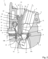
- FIG. 2 shows terminal 1 from Figure 1 in the now actuated state. It is clear that the actuating pushbutton 6 is now linearly displaced in the actuating channel 5 in the direction of the actuating axis B downwards towards the busbar 8. The actuating pushbutton 6 is guided in the direction of the actuating axis B on a sliding plane G formed by the partition 7. During the actuation of the actuating pushbutton 6, i.e. the pressing down towards the busbar 8, the clamping leg 15 of the clamping spring 11 exerts a force on the actuating pushbutton 6. The direction of the force is always less than 50° to the sliding plane G and thus essentially directed in the direction of the actuating axis B.
- the clamping leg 15 is shown in two deflection states. In the upper state, overlapping the actuating pushbutton 6, the actuating pushbutton 6 would not penetrate the connection opening 9 of the busbar 8. Then, the insertion dimension S 1 for clamping an electrical conductor would be significantly smaller than the smallest diameter of the conically tapered conductor entry channel 3. An electrical conductor would then abut the clamping end 16 and be guided by it into this constriction.
- the actual deflection state of the clamping leg 15 is the further deflected one with the insertion dimension S 2 . It is clear that a insertion dimension is achieved here that corresponds almost to the entire smallest diameter of the conically tapered conductor entry channel 3.
- the actuating pushbutton 6 dips with its actuating end 21 into the connection opening 9 of the busbar 8 with a depth T. This depth T is greater than the thickness of the busbar 8 in the area adjacent to the connection opening 9. It is clear that an electrical conductor guided by the partition 7, which is inserted into the conductor entry channel 3, is then first guided through the actuating end 21 of the actuating pushbutton 6, and only then reaches the clamping edge 17.
- the actuating end 21 of the actuating pushbutton 6 is thus located between the free end of the partition 7 pointing into the interior of the connection terminal and the clamping leg end 16.
- the clamping edge 17 of the clamping leg 15 is thus set back from the actuating end 21 of the actuating pushbutton 6.
- the actuating end 21 slides along the clamping leg 15 in the area adjacent to the bend 20 until it further bends to the clamping leg end 16. This allows for a relatively long sliding path along the clamping leg 15.
- This design in conjunction with the partition 7 extending down to adjacent to the busbar 8 and the actuating pushbutton 6 extending without a projection in the direction of the actuating axis B and acting with its actuating end 21 in alignment with the actuating axis 8, ensures that the deformation forces on the actuating pushbutton 6 are minimal.
- the interaction between the actuating pushbutton 6 and the clamping spring 11 is optimal due to the long actuating stroke.
- connection opening 9 for clamping the electrical conductor and for accommodating the clamping spring 11 can still be used to accommodate the actuating button 6 due to the angular offset of the actuating axis B and the conductor insertion axis L. This makes it possible to act on the clamping spring 11 at a point as far away as possible from the spring arch 13 in the fully actuated state, thus optimizing the force effects.
- the outwardly conically widening actuating head 22, in the fully depressed, actuated state, is adapted to the head section of the actuating channel 5, which widens conically toward the outside of the insulating housing 2.
- a step 25 on the head section, together with a step 26 in the actuating channel 5, can form a stop with which the displacement path of the actuating pushbutton 6 toward the busbar 8 is limited.
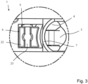
- Figure 3 omits a top view of a section of terminal 1 Figure 1 in the unactuated state. It is clear that the head section 22 has an actuation slot 23. This can also have a different shape, such as cross-shaped, square, or round.
- the partition wall 7 forming a conductor channel wall 4 between the conductor entry channel 3 and the actuation channel 5 is curved when viewed in the cross-section of the conductor entry channel 3.
- the actuation head 22 has a curved contour adapted to this. This also applies to the section of the actuation pushbutton 6 adjoining the actuation head 22 and leading to the actuation end 21, which then has a constant cross-section along its length.
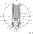
- Figure 4 shows a cross-sectional view of terminal 1 from Figure 1 in the unactuated state as a cutout.
- the actuating button 6 in the section in the width direction of the busbar 8 in the area of the actuating head 22 has a smaller width than in an adjoining central section 27 leading to the busbar 8.
- support surfaces 28a, 28b protrude laterally from the contour of the actuating pushbutton 6, which are supported on guide wall surfaces of the insulating housing 2. This support takes place in an area of the insulating housing 2 that is not as weakened by the adjacent conductor entry channel 3 as the section of the intermediate partition 7 located in the central area.
- the actuating pushbutton 6 has, at its actuating end 21 acting on the clamping leg 15, a shoulder 29a, 29b that reduces the width of the actuating end 21 compared to the central section 27 and the actuating head 22.
- This shoulder 29a, 29b forms a stop for resting on an edge region 30 of the busbar 8 that delimits the connection opening 9.
- the width of the actuating section 21, as seen in the cross-section shown, is adapted to the width of the connection opening 9 in the busbar 8 and is at least slightly smaller than this width of the connection opening 9. In this way, it is ensured that the actuating push-button 6 can be inserted into the connection opening 9.
- Figure 5 shows a cross-sectional view of terminal 1 from Figure 2 in the actuated state. It is clear that the actuating end 21 extends into the connection opening 9 of the busbar 8. The shoulders 29a, 29b formed at the transition from the widened lateral support surfaces 28a, 28b of the central section 27 to the actuating end 21 abut the edge regions 30 of the busbar 8, which laterally delimit the connection opening 9. This prevents the actuating pusher 6 from being pressed further into the connection opening 9.
- connection opening 90 is not aligned with the center of the actuating channel 5.
- actuating pushbutton 6 which is designed symmetrically overall, there is a gap in the actuating channel 5 between the side wall of the insulating housing 2 of the connection terminal 1 and the actuating pushbutton 6.
- Figure 6 shows a sectional view of another embodiment of a terminal 1. This is constructed in a similar manner to the previously described terminal 1 and has only a few modifications in this regard. Therefore, reference can essentially be made to the previous description.
- the conductor entry channel 3 initially has a cylindrical casing section M, which then merges into a conically tapered section.
- the partition 7 in this conically tapered area forms a support and sliding surface G for the actuating pushbutton 6.
- the sliding surface G is aligned parallel to the actuating axis B.
- the partition 7 is pulled down so far from the upper plane of the busbar 8 or the plane spanned by the connection opening 9 that, in the non-actuated state, the clamping leg 15 is immediately adjacent to the partition 7, possibly with a small gap.
- the actuating head 22 has a nose 31 projecting in the direction of the conductor insertion channel 3, which in the unactuated state projects freely into the conically widening head section of the actuating channel 5.
- the actuating pushbutton 6 In the area adjacent to the clamping spring 11, the actuating pushbutton 6 is designed without projections and tapers towards the actuating end 21.
- An actuating force F is exerted by the clamping leg 15 on the clamping end 21 of the actuating pushbutton 6, which, as shown, is aligned at an acute angle to the sliding plane G or the actuating axis B. This acute angle is less than 50°.
- the interior angle of the force direction F to the sliding plane G is approximately 30°.
- the actuating axis B is also offset at an angle to the conductor insertion axis L. This angle is also approximately 15° +/- 5°.
- An angle of 16° is very suitable, with the actuating axis B being perpendicular to the plane of the busbar 8 or the plane spanned by the connection opening 9 in the busbar 8.
- Figure 7 shows the connection terminal Figure 6 in the actuated state.
- the actuating pushbutton 6 is now displaced linearly in the direction of the actuating axis B or along the sliding plane G in the image plane downwards towards the busbar, so that the tapered actuating end 21 is inserted into the connection opening 9 of the busbar 8.
- the clamping leg 15 of the clamping spring 11 exerts an actuating force F on the actuating end 21, which acts at an angle of less than 50° to the sliding plane G.
- the interior angle is taken into account.
- the force acting from the clamping leg 5 on the actuating pushbutton 6 is therefore directed in the direction of the actuating axis B rather than perpendicular to it.
- the direction of the force is aligned such that it points towards the partition wall 7.
- the tilting moments acting on the actuating end 21 are therefore negligible. Due to the tapered actuating end 21, which follows the direction of extension of the sliding plane G and the actuating axis B and has no projections, such disadvantageous tilting moments and deformation energies are avoided, which could impair the stability of the actuating push button 6.
- the conductor channel wall 4 While the partition wall 7 runs in a straight line towards the actuating channel 5 below the casing receiving section M, the conductor channel wall 4 has, on the opposite side after a first inclined surface, a further end section which essentially follows the direction of extension of the conductor channel wall 4 in the casing section M. This end section then merges into the transition of the connection opening 9 for connecting the busbar 8 and thus serves as an extension of the terminal wall 10c.
- the partition wall 7 is straight towards the actuating opening 5 in the area of the guide section for the actuating pushbutton 6 towards the busbar 8.
- the partition wall 7 has a non-uniform cross-section in this guide section and forms a wall section below the casing section M that conically tapers the conductor entry channel 3.
- the end section of the conductor entry channel 3 merges into a cylindrical section or a section with a constant cross-section at the opening to the connection opening 9 in the busbar 8.
- Figure 8 shows a cross-sectional view of a section of an embodiment of the terminal 1 in the area of the actuating head 22 of the actuating push button 22. It is clear that the inner wall 40 of the actuating channel 5, which is opposite the partition 7, is inclined towards the actuating opening at the head end of the actuating channel 5 in the direction of the partition 7. This leads to a tilting of the actuating push button 6 in the direction of the partition 7 and the conductor entry channel 3 during the illustrated return of the actuating push button 6.
- This Figures 3 and 4 The visible gap or slot between the partition wall 7 and the actuating head 22 is at least largely closed. This prevents the possible ingress of dirt and/or foreign bodies, and improves the visual appearance.
- the actuating head 22 is slightly thicker in the width direction than the rest of the section. This allows the actuating opening of the actuating channel 5 to be largely filled in the width direction, except for small lateral gaps.
- the actuating pushbutton 6 is slightly tilted in the actuating channel 5 in the direction in which the terminal blocks are arranged on a mounting rail, i.e., toward the side walls. This allows the same symmetrical actuating pushbutton 6 to be used on both ends of a terminal block, thus achieving a uniform connection pattern.
- Figure 9 omits a cross-sectional view of the section Figure 8 can be seen in section AA. This clearly shows that the actuating head 22 fills the actuating channel except for small remaining gaps. It is also clear that one side wall of the conductor entry channel is open at the side. An insulating sheath of an electrical conductor to be connected can be inserted into this area, assuming the insulating function of the side wall. This allows the connection terminal, e.g., in the form of a terminal block, to be constructed more narrowly.
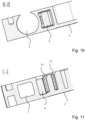
- Figure 10 omits a cross-sectional view of the section Figure 8 in section BB. It is clear that the actuating button 6 is significantly narrower in this section than in the area of the actuating head 22.
- the conductor insertion opening 3 is also open laterally in this area and is only closed all the way around with the insulating sheath of the electrical conductor to be connected or with the side wall of a terminal block arranged next to it.
- Figure 11 omits a cross-sectional view of the section Figure 8 can be seen in section CC.
- the actuating pushbutton 6 rests against the clamping leg 15 of the clamping spring, and when pressed down, slides along the clamping leg 15 toward the clamping edge.
- the conductor insertion opening 3 is now tapered in this section and closed all the way around by the insulating housing 2. The stripped end of an electrical conductor to be clamped is received in this section.
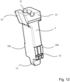
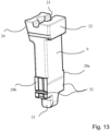
- the Figures 12 and 13 show a perspective view of the actuating button of the terminal block from Figure 7 on the front and back. It can be seen that the actuating pushbutton 6 is widened in the area of the lateral support surfaces 28a, 28b. This width, at least in the actuated state of the actuating pushbutton 6, exceeds the width or diameter of the conductor entry channel 3, so that the acting spring forces can be absorbed by the thicker lateral side walls. This is shown in Figure 11 The partition 7 can therefore be made thinner in the middle area, which results in a smaller overall design of the connection terminal.
- the actuating pushbutton 6 has groove-like recesses 32 in the area of the support surfaces 28a, 28b. These recesses can be different for different variants of the actuating pushbutton 6.
- the groove-like recesses 32 are thus codes that can be detected by means of automated optical recognition and used for automated assembly.
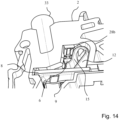
- Figure 14 shows a perspective view of terminal 1 from Figure 8 obliquely from below. It is clear that the laterally open side wall of the conductor entry channel 3 is filled by the insulating sheath of an electrical conductor 33 to be clamped. It is also visible that the actuating button rests against the clamping leg 15 of the clamping spring 11. The support surfaces protrude laterally and are located to the insulating housing 2.
Landscapes
- Connections Arranged To Contact A Plurality Of Conductors (AREA)
- Coupling Device And Connection With Printed Circuit (AREA)
- Installation Of Indoor Wiring (AREA)
- Details Of Connecting Devices For Male And Female Coupling (AREA)
- Installation Of Bus-Bars (AREA)
Priority Applications (3)
| Application Number | Priority Date | Filing Date | Title |
|---|---|---|---|
| PL18721327.7T PL3619773T5 (pl) | 2017-05-05 | 2018-04-25 | Zacisk przyłączeniowy |
| EP20180556.1A EP3731346B1 (de) | 2017-05-05 | 2018-04-25 | Anschlussklemme |
| EP21176618.3A EP3890118A1 (de) | 2017-05-05 | 2018-04-25 | Anschlussklemme |
Applications Claiming Priority (2)
| Application Number | Priority Date | Filing Date | Title |
|---|---|---|---|
| DE102017109694.9A DE102017109694B4 (de) | 2017-05-05 | 2017-05-05 | Anschlussklemme |
| PCT/EP2018/060594 WO2018202504A1 (de) | 2017-05-05 | 2018-04-25 | Anschlussklemme |
Related Child Applications (4)
| Application Number | Title | Priority Date | Filing Date |
|---|---|---|---|
| EP21176618.3A Division-Into EP3890118A1 (de) | 2017-05-05 | 2018-04-25 | Anschlussklemme |
| EP21176618.3A Division EP3890118A1 (de) | 2017-05-05 | 2018-04-25 | Anschlussklemme |
| EP20180556.1A Division-Into EP3731346B1 (de) | 2017-05-05 | 2018-04-25 | Anschlussklemme |
| EP20180556.1A Division EP3731346B1 (de) | 2017-05-05 | 2018-04-25 | Anschlussklemme |
Publications (3)
| Publication Number | Publication Date |
|---|---|
| EP3619773A1 EP3619773A1 (de) | 2020-03-11 |
| EP3619773B1 EP3619773B1 (de) | 2021-09-22 |
| EP3619773B2 true EP3619773B2 (de) | 2025-03-26 |
Family
ID=62091861
Family Applications (3)
| Application Number | Title | Priority Date | Filing Date |
|---|---|---|---|
| EP18721327.7A Active EP3619773B2 (de) | 2017-05-05 | 2018-04-25 | Anschlussklemme |
| EP20180556.1A Active EP3731346B1 (de) | 2017-05-05 | 2018-04-25 | Anschlussklemme |
| EP21176618.3A Pending EP3890118A1 (de) | 2017-05-05 | 2018-04-25 | Anschlussklemme |
Family Applications After (2)
| Application Number | Title | Priority Date | Filing Date |
|---|---|---|---|
| EP20180556.1A Active EP3731346B1 (de) | 2017-05-05 | 2018-04-25 | Anschlussklemme |
| EP21176618.3A Pending EP3890118A1 (de) | 2017-05-05 | 2018-04-25 | Anschlussklemme |
Country Status (9)
| Country | Link |
|---|---|
| US (1) | US10615519B2 (pl) |
| EP (3) | EP3619773B2 (pl) |
| JP (2) | JP7220671B2 (pl) |
| KR (1) | KR102593781B1 (pl) |
| CN (2) | CN110622358B (pl) |
| DE (2) | DE102017109694B4 (pl) |
| PL (1) | PL3619773T5 (pl) |
| RU (1) | RU2755182C2 (pl) |
| WO (1) | WO2018202504A1 (pl) |
Families Citing this family (5)
| Publication number | Priority date | Publication date | Assignee | Title |
|---|---|---|---|---|
| DE102019106353B4 (de) * | 2019-03-13 | 2023-05-25 | Phoenix Contact Gmbh & Co. Kg | Leiteranschlussklemme mit einem Betätigungselement mit angepasster Druckfläche |
| BE1027120B1 (de) | 2019-03-13 | 2020-10-14 | Phoenix Contact Gmbh & Co | Leiteranschlussklemme mit einem Betätigungselement mit angepasster Druckfläche |
| DE102020119372B4 (de) | 2020-07-22 | 2023-12-07 | WAGO Verwaltungsgesellschaft mit beschränkter Haftung | Leiteranschlussklemme |
| DE102020123282A1 (de) * | 2020-09-07 | 2022-03-10 | Phoenix Contact Gmbh & Co. Kg | Anschlussanordnung und elektronisches Gerät |
| FR3124900B1 (fr) | 2021-06-30 | 2023-12-08 | Hager Electro Sas | Borne de connexion et appareil électrique associé |
Citations (11)
| Publication number | Priority date | Publication date | Assignee | Title |
|---|---|---|---|---|
| EP1484819A2 (de) † | 2003-06-06 | 2004-12-08 | RIA-BTR Produktions GmbH | Anschlussklemme |
| DE102007022806B3 (de) † | 2007-05-11 | 2008-11-27 | Wago Verwaltungsgesellschaft Mbh | Klemmenbauteil |
| EP2112713A1 (fr) † | 2008-04-22 | 2009-10-28 | ABB France | Borne de raccordement et appareil électrique basse tension |
| DE102008060282A1 (de) † | 2008-12-03 | 2010-06-10 | Tyco Electronics Amp Gmbh | Werkzeuglos betätigbare Federklemme für elektrische Leiter |
| DE202009001488U1 (de) † | 2009-02-06 | 2010-06-24 | Weidmüller Interface GmbH & Co. KG | Anschlussklemme zum Anschluss von Leiterenden |
| DE102008060283A1 (de) † | 2008-12-03 | 2010-07-08 | Tyco Electronics Amp Gmbh | Werkzeuglos betätigbare Federklemme mit mehreren Klemmarmen für mehrere elektrische Leiter |
| WO2011047740A1 (de) † | 2009-10-22 | 2011-04-28 | Phoenix Contact Gmbh & Co. Kg | Federkraftanschlussklemme |
| EP2400595A1 (de) † | 2010-06-23 | 2011-12-28 | Wago Verwaltungsgesellschaft mbH | Anschlussklemme |
| DE102014119406A1 (de) † | 2014-12-22 | 2016-06-23 | Wago Verwaltungsgesellschaft Mbh | Anschlussklemme |
| EP3121904A1 (de) † | 2008-08-27 | 2017-01-25 | Wago Verwaltungsgesellschaft mbH | Klemmenbauelement |
| DE102016114289A1 (de) † | 2016-08-02 | 2018-02-08 | Phoenix Contact Gmbh & Co. Kg | Elektrische Anschlussklemme |
Family Cites Families (31)
| Publication number | Priority date | Publication date | Assignee | Title |
|---|---|---|---|---|
| DE2062158B2 (de) * | 1970-12-17 | 1979-04-05 | Wago-Kontakttechnik Gmbh, 4950 Minden | Schraubenlose Anschluß- oder Verbindungsklemme für elektrische Leiter |
| CH516232A (de) * | 1971-04-01 | 1971-11-30 | Oskar Woertz Inh H & O Woertz | Schraubenlose elektrische Schnell-Verbindungsklemme |
| DE3418536A1 (de) * | 1984-05-18 | 1985-11-21 | Harting Elektronik Gmbh, 4992 Espelkamp | Schraubenlose anschluss- oder verbindungsklemme |
| JP3419147B2 (ja) * | 1994-06-30 | 2003-06-23 | 松下電工株式会社 | 電線接続端子 |
| US6146187A (en) * | 1998-11-25 | 2000-11-14 | Supplie & Co. Import/Export, Inc. | Screwless terminal block |
| US6074242A (en) * | 1998-12-31 | 2000-06-13 | Methode Electronics, Inc. | Wire-trap connector for solderless compression connection |
| JP3064232U (ja) * | 1999-05-25 | 2000-01-07 | 大朗電器股▲ふん▼有限公司 | 簡単電線抜脱方式のスイッチコンセント |
| DE19940971B4 (de) * | 1999-08-20 | 2009-06-10 | Wago Verwaltungsgesellschaft Mbh | Elektrische Leiteranschlußklemme mit einer Sammelschiene |
| JP2001160431A (ja) * | 1999-09-21 | 2001-06-12 | Omron Corp | 端子台ソケット |
| CN1205697C (zh) * | 2000-08-04 | 2005-06-08 | 欧姆龙株式会社 | 电线连接器具 |
| JP3565806B2 (ja) * | 2001-08-30 | 2004-09-15 | サトーパーツ株式会社 | 端子台 |
| DE102006019150B4 (de) * | 2006-04-21 | 2011-06-09 | Wago Verwaltungsgesellschaft Mbh | Elektrische Verbindungsklemme |
| US7722384B2 (en) * | 2007-07-09 | 2010-05-25 | Ideal Industries, Inc. | In-line push-in wire connector |
| DE102007050683B4 (de) * | 2007-10-22 | 2009-09-03 | Wago Verwaltungsgesellschaft Mbh | Leiteranschlussklemme |
| JP4535168B2 (ja) * | 2008-02-12 | 2010-09-01 | パナソニック電工株式会社 | 扉付きコンセント |
| RU2375795C1 (ru) * | 2008-08-29 | 2009-12-10 | Андрей Константинович Деревенко | Соединитель электрических проводов |
| DE102008062137B4 (de) * | 2008-12-16 | 2011-06-09 | Wago Verwaltungsgesellschaft Mbh | Leiteranschlussklemme |
| DE102010015457B4 (de) * | 2010-04-16 | 2012-08-30 | Wago Verwaltungsgesellschaft Mbh | Federkraftklemmanschluss und Klemmbauelement |
| DE102011012021A1 (de) * | 2011-02-22 | 2012-08-23 | Phoenix Contact Gmbh & Co. Kg | Metallteil für eine elektronische Anschlussvorrichtung |
| US8262405B1 (en) * | 2011-03-15 | 2012-09-11 | Avx Corporation | Wire-to-wire connector |
| DE102011056410B4 (de) * | 2011-12-14 | 2013-06-27 | Wago Verwaltungsgesellschaft Mbh | Anschlussklemme |
| DE102013101406B4 (de) * | 2013-02-13 | 2018-07-12 | Wago Verwaltungsgesellschaft Mbh | Leiteranschlussklemme |
| DE102013111574B4 (de) * | 2013-10-21 | 2017-01-12 | Wago Verwaltungsgesellschaft Mbh | Federkraftklemmanschluss und Steckverbinder |
| DE102014119030A1 (de) * | 2014-12-18 | 2016-06-23 | Phoenix Contact Gmbh & Co. Kg | Anschlussklemme |
| RU2576463C1 (ru) * | 2015-01-20 | 2016-03-10 | Дмитрий Анатольевич Семаков | Соединительная клемма для электрических проводов |
| EP3116065B1 (en) * | 2015-07-07 | 2019-08-28 | TE Connectivity Germany GmbH | Push-in clamp retainer, push-in clamp assembly and electric connector element |
| US9466911B1 (en) * | 2015-10-16 | 2016-10-11 | Dinkle Enterprise Co., Ltd. | Terminal base having fastening structure |
| EP3159971B1 (en) | 2015-10-21 | 2018-09-19 | Dinkle Enterprise Co., Ltd. | Terminal base having fastening structure |
| DE102015120063B3 (de) * | 2015-11-19 | 2017-01-12 | Wago Verwaltungsgesellschaft Mbh | Leiteranschlussklemme und Betätigungswerkzeug hierzu |
| CN205565018U (zh) * | 2016-03-31 | 2016-09-07 | 宁波高松电子有限公司 | 一种改进型的斜角进线的接线端子 |
| US10418727B1 (en) * | 2018-11-15 | 2019-09-17 | Dinkle Enterprise Co., Ltd. | Rotate-to-open clamping unit and connection device having the same |
-
2017
- 2017-05-05 DE DE102017109694.9A patent/DE102017109694B4/de active Active
-
2018
- 2018-04-25 WO PCT/EP2018/060594 patent/WO2018202504A1/de not_active Ceased
- 2018-04-25 EP EP18721327.7A patent/EP3619773B2/de active Active
- 2018-04-25 CN CN201880028352.4A patent/CN110622358B/zh active Active
- 2018-04-25 KR KR1020197032436A patent/KR102593781B1/ko active Active
- 2018-04-25 JP JP2019559020A patent/JP7220671B2/ja active Active
- 2018-04-25 EP EP20180556.1A patent/EP3731346B1/de active Active
- 2018-04-25 EP EP21176618.3A patent/EP3890118A1/de active Pending
- 2018-04-25 RU RU2019132060A patent/RU2755182C2/ru active
- 2018-04-25 PL PL18721327.7T patent/PL3619773T5/pl unknown
- 2018-04-25 CN CN202111511660.2A patent/CN114221143B/zh active Active
- 2018-04-25 DE DE202018006907.8U patent/DE202018006907U1/de active Active
-
2019
- 2019-11-04 US US16/673,019 patent/US10615519B2/en active Active
-
2022
- 2022-12-23 JP JP2022206284A patent/JP7471384B2/ja active Active
Patent Citations (11)
| Publication number | Priority date | Publication date | Assignee | Title |
|---|---|---|---|---|
| EP1484819A2 (de) † | 2003-06-06 | 2004-12-08 | RIA-BTR Produktions GmbH | Anschlussklemme |
| DE102007022806B3 (de) † | 2007-05-11 | 2008-11-27 | Wago Verwaltungsgesellschaft Mbh | Klemmenbauteil |
| EP2112713A1 (fr) † | 2008-04-22 | 2009-10-28 | ABB France | Borne de raccordement et appareil électrique basse tension |
| EP3121904A1 (de) † | 2008-08-27 | 2017-01-25 | Wago Verwaltungsgesellschaft mbH | Klemmenbauelement |
| DE102008060282A1 (de) † | 2008-12-03 | 2010-06-10 | Tyco Electronics Amp Gmbh | Werkzeuglos betätigbare Federklemme für elektrische Leiter |
| DE102008060283A1 (de) † | 2008-12-03 | 2010-07-08 | Tyco Electronics Amp Gmbh | Werkzeuglos betätigbare Federklemme mit mehreren Klemmarmen für mehrere elektrische Leiter |
| DE202009001488U1 (de) † | 2009-02-06 | 2010-06-24 | Weidmüller Interface GmbH & Co. KG | Anschlussklemme zum Anschluss von Leiterenden |
| WO2011047740A1 (de) † | 2009-10-22 | 2011-04-28 | Phoenix Contact Gmbh & Co. Kg | Federkraftanschlussklemme |
| EP2400595A1 (de) † | 2010-06-23 | 2011-12-28 | Wago Verwaltungsgesellschaft mbH | Anschlussklemme |
| DE102014119406A1 (de) † | 2014-12-22 | 2016-06-23 | Wago Verwaltungsgesellschaft Mbh | Anschlussklemme |
| DE102016114289A1 (de) † | 2016-08-02 | 2018-02-08 | Phoenix Contact Gmbh & Co. Kg | Elektrische Anschlussklemme |
Also Published As
| Publication number | Publication date |
|---|---|
| WO2018202504A1 (de) | 2018-11-08 |
| KR102593781B1 (ko) | 2023-10-25 |
| EP3619773B1 (de) | 2021-09-22 |
| PL3619773T5 (pl) | 2025-07-28 |
| EP3890118A1 (de) | 2021-10-06 |
| JP2023036817A (ja) | 2023-03-14 |
| CN110622358B (zh) | 2022-01-14 |
| EP3731346B1 (de) | 2024-09-11 |
| RU2019132060A (ru) | 2021-06-07 |
| US10615519B2 (en) | 2020-04-07 |
| JP2020518954A (ja) | 2020-06-25 |
| JP7220671B2 (ja) | 2023-02-10 |
| CN114221143B (zh) | 2024-06-04 |
| RU2755182C2 (ru) | 2021-09-14 |
| CN114221143A (zh) | 2022-03-22 |
| EP3731346C0 (de) | 2024-09-11 |
| JP7471384B2 (ja) | 2024-04-19 |
| US20200067212A1 (en) | 2020-02-27 |
| DE102017109694B4 (de) | 2022-10-06 |
| DE202018006907U1 (de) | 2024-05-16 |
| DE102017109694A1 (de) | 2018-11-08 |
| KR20200004304A (ko) | 2020-01-13 |
| PL3619773T3 (pl) | 2022-02-07 |
| CN110622358A (zh) | 2019-12-27 |
| EP3619773A1 (de) | 2020-03-11 |
| EP3731346A1 (de) | 2020-10-28 |
Similar Documents
| Publication | Publication Date | Title |
|---|---|---|
| EP3619773B2 (de) | Anschlussklemme | |
| EP3477775B1 (de) | Leiteranschlussklemme und kontakteinsatz | |
| EP2786447B1 (de) | Anschlussklemme mit einer stegförmigen leiterführung | |
| DE4432140C2 (de) | Elektrischer Steckverbinder | |
| DE1122603B (de) | Steckerbuchse | |
| EP0554810A2 (de) | Elektrischer Verbinder | |
| EP4068519B1 (de) | Leiteranschlussklemme, klemmfeder einer leiteranschlussklemme sowie reihenklemme | |
| EP2953213A1 (de) | Steckverbinderanordnung und kodierelement hierzu sowie verfahren zur kodierung einer steckverbinderanordnung | |
| DE2547166A1 (de) | Elektrische verbinderanordnung | |
| EP3855571A1 (de) | Anschlussklemme und elektronisches gerät | |
| EP3849019B1 (de) | Leiteranschlussklemme | |
| CH647092A5 (de) | Drucktastenschalter. | |
| DE102019120306B4 (de) | Leiteranschlussklemme zum Anschluss wenigstens eines elektrischen Leiters | |
| EP3776740B1 (de) | Reihenklemme | |
| EP0743708B1 (de) | Sammelschienen-Anschlussklemme | |
| DE3709519C1 (en) | Terminal for the detachable connection of at least one conductor | |
| DE3323861C2 (pl) | ||
| DE9310650U1 (de) | Kabelsteckverbinder | |
| DE3914872A1 (de) | Steckkontakttraeger aus kunststoff mit flachstecker | |
| EP3675300A1 (de) | Adapter zur positionierung und befestigung eines installationsgehäuses | |
| DE102016005134B4 (de) | Drucktastenschalter | |
| DE102023130931A1 (de) | Kodierbauteil und Kodierelement sowie Set aus Steckverbinder und Kodierbauteil | |
| EP1280235B1 (de) | Anschlussklemmeinrichtung mit innen liegendem Klemmkontakt | |
| DE202024102562U1 (de) | Federkraftklemmanschluss und Leiteranschlussklemme | |
| EP1611652B1 (de) | Verriegelungselement zur befestigung eines installationsgerätes für sammelschienen |
Legal Events
| Date | Code | Title | Description |
|---|---|---|---|
| STAA | Information on the status of an ep patent application or granted ep patent |
Free format text: STATUS: UNKNOWN |
|
| STAA | Information on the status of an ep patent application or granted ep patent |
Free format text: STATUS: THE INTERNATIONAL PUBLICATION HAS BEEN MADE |
|
| PUAI | Public reference made under article 153(3) epc to a published international application that has entered the european phase |
Free format text: ORIGINAL CODE: 0009012 |
|
| STAA | Information on the status of an ep patent application or granted ep patent |
Free format text: STATUS: REQUEST FOR EXAMINATION WAS MADE |
|
| 17P | Request for examination filed |
Effective date: 20191021 |
|
| AK | Designated contracting states |
Kind code of ref document: A1 Designated state(s): AL AT BE BG CH CY CZ DE DK EE ES FI FR GB GR HR HU IE IS IT LI LT LU LV MC MK MT NL NO PL PT RO RS SE SI SK SM TR |
|
| AX | Request for extension of the european patent |
Extension state: BA ME |
|
| DAV | Request for validation of the european patent (deleted) | ||
| DAX | Request for extension of the european patent (deleted) | ||
| GRAP | Despatch of communication of intention to grant a patent |
Free format text: ORIGINAL CODE: EPIDOSNIGR1 |
|
| STAA | Information on the status of an ep patent application or granted ep patent |
Free format text: STATUS: GRANT OF PATENT IS INTENDED |
|
| INTG | Intention to grant announced |
Effective date: 20210507 |
|
| GRAS | Grant fee paid |
Free format text: ORIGINAL CODE: EPIDOSNIGR3 |
|
| GRAA | (expected) grant |
Free format text: ORIGINAL CODE: 0009210 |
|
| STAA | Information on the status of an ep patent application or granted ep patent |
Free format text: STATUS: THE PATENT HAS BEEN GRANTED |
|
| AK | Designated contracting states |
Kind code of ref document: B1 Designated state(s): AL AT BE BG CH CY CZ DE DK EE ES FI FR GB GR HR HU IE IS IT LI LT LU LV MC MK MT NL NO PL PT RO RS SE SI SK SM TR |
|
| REG | Reference to a national code |
Ref country code: GB Ref legal event code: FG4D Free format text: NOT ENGLISH |
|
| REG | Reference to a national code |
Ref country code: DE Ref legal event code: R096 Ref document number: 502018007171 Country of ref document: DE |
|
| REG | Reference to a national code |
Ref country code: IE Ref legal event code: FG4D Free format text: LANGUAGE OF EP DOCUMENT: GERMAN |
|
| REG | Reference to a national code |
Ref country code: CH Ref legal event code: EP Ref country code: AT Ref legal event code: REF Ref document number: 1433031 Country of ref document: AT Kind code of ref document: T Effective date: 20211015 |
|
| REG | Reference to a national code |
Ref country code: LT Ref legal event code: MG9D |
|
| REG | Reference to a national code |
Ref country code: NL Ref legal event code: MP Effective date: 20210922 |
|
| PG25 | Lapsed in a contracting state [announced via postgrant information from national office to epo] |
Ref country code: NO Free format text: LAPSE BECAUSE OF FAILURE TO SUBMIT A TRANSLATION OF THE DESCRIPTION OR TO PAY THE FEE WITHIN THE PRESCRIBED TIME-LIMIT Effective date: 20211222 Ref country code: BG Free format text: LAPSE BECAUSE OF FAILURE TO SUBMIT A TRANSLATION OF THE DESCRIPTION OR TO PAY THE FEE WITHIN THE PRESCRIBED TIME-LIMIT Effective date: 20211222 Ref country code: LT Free format text: LAPSE BECAUSE OF FAILURE TO SUBMIT A TRANSLATION OF THE DESCRIPTION OR TO PAY THE FEE WITHIN THE PRESCRIBED TIME-LIMIT Effective date: 20210922 Ref country code: RS Free format text: LAPSE BECAUSE OF FAILURE TO SUBMIT A TRANSLATION OF THE DESCRIPTION OR TO PAY THE FEE WITHIN THE PRESCRIBED TIME-LIMIT Effective date: 20210922 Ref country code: SE Free format text: LAPSE BECAUSE OF FAILURE TO SUBMIT A TRANSLATION OF THE DESCRIPTION OR TO PAY THE FEE WITHIN THE PRESCRIBED TIME-LIMIT Effective date: 20210922 Ref country code: HR Free format text: LAPSE BECAUSE OF FAILURE TO SUBMIT A TRANSLATION OF THE DESCRIPTION OR TO PAY THE FEE WITHIN THE PRESCRIBED TIME-LIMIT Effective date: 20210922 Ref country code: FI Free format text: LAPSE BECAUSE OF FAILURE TO SUBMIT A TRANSLATION OF THE DESCRIPTION OR TO PAY THE FEE WITHIN THE PRESCRIBED TIME-LIMIT Effective date: 20210922 |
|
| PG25 | Lapsed in a contracting state [announced via postgrant information from national office to epo] |
Ref country code: LV Free format text: LAPSE BECAUSE OF FAILURE TO SUBMIT A TRANSLATION OF THE DESCRIPTION OR TO PAY THE FEE WITHIN THE PRESCRIBED TIME-LIMIT Effective date: 20210922 Ref country code: GR Free format text: LAPSE BECAUSE OF FAILURE TO SUBMIT A TRANSLATION OF THE DESCRIPTION OR TO PAY THE FEE WITHIN THE PRESCRIBED TIME-LIMIT Effective date: 20211223 |
|
| PG25 | Lapsed in a contracting state [announced via postgrant information from national office to epo] |
Ref country code: IS Free format text: LAPSE BECAUSE OF FAILURE TO SUBMIT A TRANSLATION OF THE DESCRIPTION OR TO PAY THE FEE WITHIN THE PRESCRIBED TIME-LIMIT Effective date: 20220122 Ref country code: SK Free format text: LAPSE BECAUSE OF FAILURE TO SUBMIT A TRANSLATION OF THE DESCRIPTION OR TO PAY THE FEE WITHIN THE PRESCRIBED TIME-LIMIT Effective date: 20210922 Ref country code: RO Free format text: LAPSE BECAUSE OF FAILURE TO SUBMIT A TRANSLATION OF THE DESCRIPTION OR TO PAY THE FEE WITHIN THE PRESCRIBED TIME-LIMIT Effective date: 20210922 Ref country code: PT Free format text: LAPSE BECAUSE OF FAILURE TO SUBMIT A TRANSLATION OF THE DESCRIPTION OR TO PAY THE FEE WITHIN THE PRESCRIBED TIME-LIMIT Effective date: 20220124 Ref country code: NL Free format text: LAPSE BECAUSE OF FAILURE TO SUBMIT A TRANSLATION OF THE DESCRIPTION OR TO PAY THE FEE WITHIN THE PRESCRIBED TIME-LIMIT Effective date: 20210922 Ref country code: ES Free format text: LAPSE BECAUSE OF FAILURE TO SUBMIT A TRANSLATION OF THE DESCRIPTION OR TO PAY THE FEE WITHIN THE PRESCRIBED TIME-LIMIT Effective date: 20210922 Ref country code: EE Free format text: LAPSE BECAUSE OF FAILURE TO SUBMIT A TRANSLATION OF THE DESCRIPTION OR TO PAY THE FEE WITHIN THE PRESCRIBED TIME-LIMIT Effective date: 20210922 Ref country code: CZ Free format text: LAPSE BECAUSE OF FAILURE TO SUBMIT A TRANSLATION OF THE DESCRIPTION OR TO PAY THE FEE WITHIN THE PRESCRIBED TIME-LIMIT Effective date: 20210922 Ref country code: AL Free format text: LAPSE BECAUSE OF FAILURE TO SUBMIT A TRANSLATION OF THE DESCRIPTION OR TO PAY THE FEE WITHIN THE PRESCRIBED TIME-LIMIT Effective date: 20210922 |
|
| REG | Reference to a national code |
Ref country code: DE Ref legal event code: R026 Ref document number: 502018007171 Country of ref document: DE |
|
| PLBI | Opposition filed |
Free format text: ORIGINAL CODE: 0009260 |
|
| PLAX | Notice of opposition and request to file observation + time limit sent |
Free format text: ORIGINAL CODE: EPIDOSNOBS2 |
|
| PG25 | Lapsed in a contracting state [announced via postgrant information from national office to epo] |
Ref country code: DK Free format text: LAPSE BECAUSE OF FAILURE TO SUBMIT A TRANSLATION OF THE DESCRIPTION OR TO PAY THE FEE WITHIN THE PRESCRIBED TIME-LIMIT Effective date: 20210922 |
|
| 26 | Opposition filed |
Opponent name: PHOENIX CONTACT GMBH & CO. KG Effective date: 20220622 |
|
| PLBB | Reply of patent proprietor to notice(s) of opposition received |
Free format text: ORIGINAL CODE: EPIDOSNOBS3 |
|
| PG25 | Lapsed in a contracting state [announced via postgrant information from national office to epo] |
Ref country code: SI Free format text: LAPSE BECAUSE OF FAILURE TO SUBMIT A TRANSLATION OF THE DESCRIPTION OR TO PAY THE FEE WITHIN THE PRESCRIBED TIME-LIMIT Effective date: 20210922 |
|
| REG | Reference to a national code |
Ref country code: BE Ref legal event code: MM Effective date: 20220430 |
|
| PG25 | Lapsed in a contracting state [announced via postgrant information from national office to epo] |
Ref country code: MC Free format text: LAPSE BECAUSE OF FAILURE TO SUBMIT A TRANSLATION OF THE DESCRIPTION OR TO PAY THE FEE WITHIN THE PRESCRIBED TIME-LIMIT Effective date: 20210922 Ref country code: LU Free format text: LAPSE BECAUSE OF NON-PAYMENT OF DUE FEES Effective date: 20220425 |
|
| PG25 | Lapsed in a contracting state [announced via postgrant information from national office to epo] |
Ref country code: BE Free format text: LAPSE BECAUSE OF NON-PAYMENT OF DUE FEES Effective date: 20220430 |
|
| REG | Reference to a national code |
Ref country code: DE Ref legal event code: R082 Ref document number: 502018007171 Country of ref document: DE Representative=s name: MEISSNER BOLTE PATENTANWAELTE RECHTSANWAELTE P, DE |
|
| PG25 | Lapsed in a contracting state [announced via postgrant information from national office to epo] |
Ref country code: IE Free format text: LAPSE BECAUSE OF NON-PAYMENT OF DUE FEES Effective date: 20220425 |
|
| P01 | Opt-out of the competence of the unified patent court (upc) registered |
Effective date: 20230516 |
|
| APBM | Appeal reference recorded |
Free format text: ORIGINAL CODE: EPIDOSNREFNO |
|
| APBP | Date of receipt of notice of appeal recorded |
Free format text: ORIGINAL CODE: EPIDOSNNOA2O |
|
| APAH | Appeal reference modified |
Free format text: ORIGINAL CODE: EPIDOSCREFNO |
|
| APBU | Appeal procedure closed |
Free format text: ORIGINAL CODE: EPIDOSNNOA9O |
|
| RAP4 | Party data changed (patent owner data changed or rights of a patent transferred) |
Owner name: WAGO VERWALTUNGSGESELLSCHAFT MBH |
|
| RAP4 | Party data changed (patent owner data changed or rights of a patent transferred) |
Owner name: WAGO VERWALTUNGSGESELLSCHAFT MBH |
|
| PG25 | Lapsed in a contracting state [announced via postgrant information from national office to epo] |
Ref country code: SM Free format text: LAPSE BECAUSE OF FAILURE TO SUBMIT A TRANSLATION OF THE DESCRIPTION OR TO PAY THE FEE WITHIN THE PRESCRIBED TIME-LIMIT Effective date: 20210922 Ref country code: MK Free format text: LAPSE BECAUSE OF FAILURE TO SUBMIT A TRANSLATION OF THE DESCRIPTION OR TO PAY THE FEE WITHIN THE PRESCRIBED TIME-LIMIT Effective date: 20210922 Ref country code: CY Free format text: LAPSE BECAUSE OF FAILURE TO SUBMIT A TRANSLATION OF THE DESCRIPTION OR TO PAY THE FEE WITHIN THE PRESCRIBED TIME-LIMIT Effective date: 20210922 |
|
| PG25 | Lapsed in a contracting state [announced via postgrant information from national office to epo] |
Ref country code: HU Free format text: LAPSE BECAUSE OF FAILURE TO SUBMIT A TRANSLATION OF THE DESCRIPTION OR TO PAY THE FEE WITHIN THE PRESCRIBED TIME-LIMIT; INVALID AB INITIO Effective date: 20180425 |
|
| REG | Reference to a national code |
Ref country code: AT Ref legal event code: MM01 Ref document number: 1433031 Country of ref document: AT Kind code of ref document: T Effective date: 20230425 |
|
| PG25 | Lapsed in a contracting state [announced via postgrant information from national office to epo] |
Ref country code: AT Free format text: LAPSE BECAUSE OF NON-PAYMENT OF DUE FEES Effective date: 20230425 |
|
| PG25 | Lapsed in a contracting state [announced via postgrant information from national office to epo] |
Ref country code: AT Free format text: LAPSE BECAUSE OF NON-PAYMENT OF DUE FEES Effective date: 20230425 |
|
| PG25 | Lapsed in a contracting state [announced via postgrant information from national office to epo] |
Ref country code: MT Free format text: LAPSE BECAUSE OF FAILURE TO SUBMIT A TRANSLATION OF THE DESCRIPTION OR TO PAY THE FEE WITHIN THE PRESCRIBED TIME-LIMIT Effective date: 20210922 |
|
| PUAH | Patent maintained in amended form |
Free format text: ORIGINAL CODE: 0009272 |
|
| STAA | Information on the status of an ep patent application or granted ep patent |
Free format text: STATUS: PATENT MAINTAINED AS AMENDED |
|
| 27A | Patent maintained in amended form |
Effective date: 20250326 |
|
| AK | Designated contracting states |
Kind code of ref document: B2 Designated state(s): AL AT BE BG CH CY CZ DE DK EE ES FI FR GB GR HR HU IE IS IT LI LT LU LV MC MK MT NL NO PL PT RO RS SE SI SK SM TR |
|
| REG | Reference to a national code |
Ref country code: DE Ref legal event code: R102 Ref document number: 502018007171 Country of ref document: DE |
|
| PGFP | Annual fee paid to national office [announced via postgrant information from national office to epo] |
Ref country code: DE Payment date: 20250428 Year of fee payment: 8 |
|
| PGFP | Annual fee paid to national office [announced via postgrant information from national office to epo] |
Ref country code: GB Payment date: 20250422 Year of fee payment: 8 |
|
| PGFP | Annual fee paid to national office [announced via postgrant information from national office to epo] |
Ref country code: IT Payment date: 20250422 Year of fee payment: 8 |
|
| PGFP | Annual fee paid to national office [announced via postgrant information from national office to epo] |
Ref country code: FR Payment date: 20250424 Year of fee payment: 8 |
|
| PGFP | Annual fee paid to national office [announced via postgrant information from national office to epo] |
Ref country code: CH Payment date: 20250501 Year of fee payment: 8 |
|
| PGFP | Annual fee paid to national office [announced via postgrant information from national office to epo] |
Ref country code: TR Payment date: 20250414 Year of fee payment: 8 |
|
| PGFP | Annual fee paid to national office [announced via postgrant information from national office to epo] |
Ref country code: PL Payment date: 20250414 Year of fee payment: 8 |