EP3617542B1 - Jonction antirotation d'un boulon de frein a disque - Google Patents
Jonction antirotation d'un boulon de frein a disque Download PDFInfo
- Publication number
- EP3617542B1 EP3617542B1 EP19204415.4A EP19204415A EP3617542B1 EP 3617542 B1 EP3617542 B1 EP 3617542B1 EP 19204415 A EP19204415 A EP 19204415A EP 3617542 B1 EP3617542 B1 EP 3617542B1
- Authority
- EP
- European Patent Office
- Prior art keywords
- guide sleeve
- receiving portion
- guide
- brake
- brake carrier
- Prior art date
- Legal status (The legal status is an assumption and is not a legal conclusion. Google has not performed a legal analysis and makes no representation as to the accuracy of the status listed.)
- Active
Links
- 238000013519 translation Methods 0.000 claims description 7
- 238000000034 method Methods 0.000 description 4
- 230000000694 effects Effects 0.000 description 3
- 230000000712 assembly Effects 0.000 description 2
- 238000000429 assembly Methods 0.000 description 2
- 230000005540 biological transmission Effects 0.000 description 2
- 239000003623 enhancer Substances 0.000 description 2
- 238000007789 sealing Methods 0.000 description 2
- 238000013459 approach Methods 0.000 description 1
- 238000005520 cutting process Methods 0.000 description 1
- 238000005553 drilling Methods 0.000 description 1
- 238000009434 installation Methods 0.000 description 1
- 238000003754 machining Methods 0.000 description 1
- 239000000463 material Substances 0.000 description 1
- 238000003801 milling Methods 0.000 description 1
- 238000012986 modification Methods 0.000 description 1
- 230000004048 modification Effects 0.000 description 1
- 239000004810 polytetrafluoroethylene Substances 0.000 description 1
- 229920001343 polytetrafluoroethylene Polymers 0.000 description 1
- 208000024891 symptom Diseases 0.000 description 1
- 238000012360 testing method Methods 0.000 description 1
Images


Classifications
-
- F—MECHANICAL ENGINEERING; LIGHTING; HEATING; WEAPONS; BLASTING
- F16—ENGINEERING ELEMENTS AND UNITS; GENERAL MEASURES FOR PRODUCING AND MAINTAINING EFFECTIVE FUNCTIONING OF MACHINES OR INSTALLATIONS; THERMAL INSULATION IN GENERAL
- F16D—COUPLINGS FOR TRANSMITTING ROTATION; CLUTCHES; BRAKES
- F16D55/00—Brakes with substantially-radial braking surfaces pressed together in axial direction, e.g. disc brakes
- F16D55/02—Brakes with substantially-radial braking surfaces pressed together in axial direction, e.g. disc brakes with axially-movable discs or pads pressed against axially-located rotating members
- F16D55/22—Brakes with substantially-radial braking surfaces pressed together in axial direction, e.g. disc brakes with axially-movable discs or pads pressed against axially-located rotating members by clamping an axially-located rotating disc between movable braking members, e.g. movable brake discs or brake pads
- F16D55/224—Brakes with substantially-radial braking surfaces pressed together in axial direction, e.g. disc brakes with axially-movable discs or pads pressed against axially-located rotating members by clamping an axially-located rotating disc between movable braking members, e.g. movable brake discs or brake pads with a common actuating member for the braking members
- F16D55/225—Brakes with substantially-radial braking surfaces pressed together in axial direction, e.g. disc brakes with axially-movable discs or pads pressed against axially-located rotating members by clamping an axially-located rotating disc between movable braking members, e.g. movable brake discs or brake pads with a common actuating member for the braking members the braking members being brake pads
- F16D55/226—Brakes with substantially-radial braking surfaces pressed together in axial direction, e.g. disc brakes with axially-movable discs or pads pressed against axially-located rotating members by clamping an axially-located rotating disc between movable braking members, e.g. movable brake discs or brake pads with a common actuating member for the braking members the braking members being brake pads in which the common actuating member is moved axially, e.g. floating caliper disc brakes
- F16D55/2265—Brakes with substantially-radial braking surfaces pressed together in axial direction, e.g. disc brakes with axially-movable discs or pads pressed against axially-located rotating members by clamping an axially-located rotating disc between movable braking members, e.g. movable brake discs or brake pads with a common actuating member for the braking members the braking members being brake pads in which the common actuating member is moved axially, e.g. floating caliper disc brakes the axial movement being guided by one or more pins engaging bores in the brake support or the brake housing
- F16D55/22655—Constructional details of guide pins
-
- F—MECHANICAL ENGINEERING; LIGHTING; HEATING; WEAPONS; BLASTING
- F16—ENGINEERING ELEMENTS AND UNITS; GENERAL MEASURES FOR PRODUCING AND MAINTAINING EFFECTIVE FUNCTIONING OF MACHINES OR INSTALLATIONS; THERMAL INSULATION IN GENERAL
- F16D—COUPLINGS FOR TRANSMITTING ROTATION; CLUTCHES; BRAKES
- F16D55/00—Brakes with substantially-radial braking surfaces pressed together in axial direction, e.g. disc brakes
- F16D55/02—Brakes with substantially-radial braking surfaces pressed together in axial direction, e.g. disc brakes with axially-movable discs or pads pressed against axially-located rotating members
- F16D55/22—Brakes with substantially-radial braking surfaces pressed together in axial direction, e.g. disc brakes with axially-movable discs or pads pressed against axially-located rotating members by clamping an axially-located rotating disc between movable braking members, e.g. movable brake discs or brake pads
- F16D55/224—Brakes with substantially-radial braking surfaces pressed together in axial direction, e.g. disc brakes with axially-movable discs or pads pressed against axially-located rotating members by clamping an axially-located rotating disc between movable braking members, e.g. movable brake discs or brake pads with a common actuating member for the braking members
- F16D55/225—Brakes with substantially-radial braking surfaces pressed together in axial direction, e.g. disc brakes with axially-movable discs or pads pressed against axially-located rotating members by clamping an axially-located rotating disc between movable braking members, e.g. movable brake discs or brake pads with a common actuating member for the braking members the braking members being brake pads
- F16D55/226—Brakes with substantially-radial braking surfaces pressed together in axial direction, e.g. disc brakes with axially-movable discs or pads pressed against axially-located rotating members by clamping an axially-located rotating disc between movable braking members, e.g. movable brake discs or brake pads with a common actuating member for the braking members the braking members being brake pads in which the common actuating member is moved axially, e.g. floating caliper disc brakes
- F16D55/2265—Brakes with substantially-radial braking surfaces pressed together in axial direction, e.g. disc brakes with axially-movable discs or pads pressed against axially-located rotating members by clamping an axially-located rotating disc between movable braking members, e.g. movable brake discs or brake pads with a common actuating member for the braking members the braking members being brake pads in which the common actuating member is moved axially, e.g. floating caliper disc brakes the axial movement being guided by one or more pins engaging bores in the brake support or the brake housing
- F16D55/227—Brakes with substantially-radial braking surfaces pressed together in axial direction, e.g. disc brakes with axially-movable discs or pads pressed against axially-located rotating members by clamping an axially-located rotating disc between movable braking members, e.g. movable brake discs or brake pads with a common actuating member for the braking members the braking members being brake pads in which the common actuating member is moved axially, e.g. floating caliper disc brakes the axial movement being guided by one or more pins engaging bores in the brake support or the brake housing by two or more pins
-
- F—MECHANICAL ENGINEERING; LIGHTING; HEATING; WEAPONS; BLASTING
- F16—ENGINEERING ELEMENTS AND UNITS; GENERAL MEASURES FOR PRODUCING AND MAINTAINING EFFECTIVE FUNCTIONING OF MACHINES OR INSTALLATIONS; THERMAL INSULATION IN GENERAL
- F16D—COUPLINGS FOR TRANSMITTING ROTATION; CLUTCHES; BRAKES
- F16D65/00—Parts or details
- F16D65/005—Components of axially engaging brakes not otherwise provided for
- F16D65/0087—Brake housing guide members, e.g. caliper pins; Accessories therefor, e.g. dust boots
-
- F—MECHANICAL ENGINEERING; LIGHTING; HEATING; WEAPONS; BLASTING
- F16—ENGINEERING ELEMENTS AND UNITS; GENERAL MEASURES FOR PRODUCING AND MAINTAINING EFFECTIVE FUNCTIONING OF MACHINES OR INSTALLATIONS; THERMAL INSULATION IN GENERAL
- F16D—COUPLINGS FOR TRANSMITTING ROTATION; CLUTCHES; BRAKES
- F16D55/00—Brakes with substantially-radial braking surfaces pressed together in axial direction, e.g. disc brakes
- F16D2055/0004—Parts or details of disc brakes
- F16D2055/007—Pins holding the braking members
-
- F—MECHANICAL ENGINEERING; LIGHTING; HEATING; WEAPONS; BLASTING
- F16—ENGINEERING ELEMENTS AND UNITS; GENERAL MEASURES FOR PRODUCING AND MAINTAINING EFFECTIVE FUNCTIONING OF MACHINES OR INSTALLATIONS; THERMAL INSULATION IN GENERAL
- F16D—COUPLINGS FOR TRANSMITTING ROTATION; CLUTCHES; BRAKES
- F16D2250/00—Manufacturing; Assembly
- F16D2250/0084—Assembly or disassembly
Definitions
- the present invention relates to a disc brake.
- the present invention relates to a rotational fixing for a guide pin of a disc brake and a method of fixing a guide pin of a disc brake.
- Disc brakes are commonly used for braking heavy vehicles such as trucks, buses and coaches.
- Disc brakes conventionally comprise a brake carrier, a caliper and a rotor.
- the carrier is arranged to carry brake pads on each side of the rotor.
- the caliper is slidably mounted on the brake carrier by two or more guide assemblies, such that when the disc brake is actuated, the caliper is able to slide with respect to the brake carrier. As the caliper slides inboard, the brake pads are urged onto the opposing faces of the rotor in a clamping action and a braking action is effected.
- a guide assembly typically comprises a guide pin along which the caliper can slide and a bore disposed in the caliper for receiving the guide pin.
- each guide pin comprises a smooth outer guide sleeve along which the caliper slides and a guide bolt which extends through the guide sleeve and is screwed into a bore of the brake carrier to retain the guide sleeve.
- Document DE10150214A1 discloses a disk brake, for commercial vehicles, that has structured mountings for the brake saddle at the brake carrier, with a sliding bush around a guide bar at one carrier mounting.
- the present invention seeks to overcome or at least mitigate the problems of the prior art.
- a first aspect of the invention provides a disc brake according to claim 1, comprising a rotational fixing for the guide pin of the disc brake.
- the fixing restricts movement of the guide pin relative to the brake carrier by inter-locking the guide sleeve of the guide pin and the brake carrier.
- the rotational fixing for a guide pin of a disc brake comprises: a guide sleeve; a receiving portion of a brake carrier to receive the sleeve portion; and an inter-connection to engage the sleeve portion and receiving portion so as to restrict rotation of the guide sleeve relative to the brake carrier, when the sleeve portion is received by the receiving portion.
- the rotational fixing By engaging the sleeve and receiving portion, the rotational fixing is able to substantially inhibit, rotational movement of the guide sleeve relative to the brake carrier in a clockwise direction and/or anti-clockwise direction.
- the rotational fixing is able to substantially avoid, undesirable rotational movement of the guide sleeve relative to the brake carrier caused by a changing torque acting on the disc brake as a vehicle moves repeatedly forwardly and backwardly.
- the transmission of rotation from the guide sleeve to the guide bolt of the guide pin and consequential loosening of the guide bolt is thereby substantially averted.
- the inter-connection is also configured to engage the sleeve portion and receiving portion so as to restrict translation of the guide sleeve relative to the brake carrier, when the sleeve portion is received by the receiving portion.
- the rotational fixing is able to substantially impede lateral translational movement of the guide sleeve relative to the brake carrier in the circumferential direction X and perpendicular translational movement of the guide sleeve relative to the brake carrier in the tangential direction Y.
- the rotational fixing is able to forestall any undesirable movement (rotational and translational) of guide sleeve relative to the brake carrier caused by dynamic loads acting on the disc brake.
- the sleeve portion of the guide sleeve may be a first end portion of the guide sleeve or a rim at the first end of the guide sleeve.
- the sleeve portion may alternatively comprise a flange arranged at the first end of the guide sleeve comprising an outer edge and a flange face.
- the receiving portion is configured to receive the sleeve portion such that, when received, the guide sleeve extends from the brake carrier in an axial direction A.
- the receiving portion of the brake carrier may comprise a receiving face against which the sleeve portion is located when the sleeve portion is received by the receiving portion and which defines the region where the guide sleeve is mounted on the brake carrier.
- the receiving portion may be deformable during the assembly of the rotational fixing.
- the receiving face may be a surface region of an inboard surface of the brake carrier, wherein the receiving face is substantially flush with the inboard surface of the brake carrier.
- the receiving portion may comprise a recess formed in the brake carrier in which the sleeve portion can be fitted so as to further restrict translational movement between the guide sleeve and the brake carrier, and the receiving face is disposed in the recess.
- the inter-connection may comprise a connector that is locatable between the sleeve portion and receiving portion to form an engagement.
- the connector may be locatable to extend in the axial direction A between the sleeve portion and the receiving portion.
- the connector may be locatable to extend in a radial direction between the sleeve portion and the receiving portion, perpendicular to the axial direction A in which the guide sleeve is mounted on the brake carrier.
- the inter-connection may comprise a first cavity formed in the sleeve portion to receive a first part of the connector and a second cavity formed in the receiving portion to receive a second part of the connector, wherein the connector is co-locatable in the first cavity and the second cavity so as to engage the guide sleeve and brake carrier when the sleeve portion is received by the receiving portion.
- the first cavity may be formed in the flange face.
- the second cavity may be formed in the receiving face.
- the first cavity and first part of the connector are preferably configured to form an interference or press-fit connection.
- the second cavity and second part of the connector is preferably configured to form an interference or press-fit connection.
- the first cavity may be a pre-formed first cavity in the sleeve portion, formed prior to receiving the first part of the connector.
- the second cavity may be a pre-formed second cavity in the receiving portion, formed prior to receiving the second part of the connector. If the receiving portion is deformable, the pre-formed second cavity may be a deformable as the second part of the connector is received in the pre-formed second cavity so as to enhance the interference or press-fit connection and minimise tolerances.
- the second cavity may be a formable second cavity in the receiving portion, formed when the sleeve portion is received in the receiving portion and the connector is pushed against the deformable receiving portion to form a cavity in which the second part of the connector is received.
- the connector may comprise a cylinder, cuboid, sphere, ovoid, ellipsoid or any other suitably shaped body.
- the connector may be a ball-like connector with a substantially spherical body
- the first cavity may be a first semi-circular cavity configured to receive a first sector of the ball
- the second cavity may be a second semi-circular cavity configured to receive a second sector of the ball
- the ball is co-locatable in the first cavity and the second cavity to engage the guide sleeve and brake carrier when the sleeve portion is received by the receiving portion.
- the ball connector may be a ball bearing.
- the connector may be a pin-like connector with an elongate body
- the first cavity may be configured to receive the first end of the pin
- the second cavity may be configured to receive the second end of the pin
- the pin is co-locatable in the first cavity and the second cavity so as to engage the guide sleeve and brake carrier when the sleeve portion is received by the receiving portion.
- the inter-connection may comprise a protrusion and indent to receive the protrusion.
- the protrusion may be configured to extend from the sleeve portion or the receiving portion.
- the protrusion may be a blade or tooth extending outwardly from the sleeve portion or receiving portion.
- the indent may be formed in the corresponding portion to receive the protrusion and thereby engage the guide sleeve and the brake carrier, when the sleeve portion is received by the receiving portion.
- the indent may be a pre-formed indent, formed in a portion prior to the sleeve portion being received by the recessing portion and the protrusion being received in the indent.
- the indent may be a formable indent in the receiving portion, formed when the sleeve portion is received by the receiving portion and the protrusion is pushed against the deformable receiving portion.
- the protrusion may be configured to extend in an axial direction A or radial direction between the sleeve portion and receiving portion into the indent.
- a second aspect of the invention relates to a disc brake comprising:
- the guide pin may comprise a guide bolt and the disc brake may further comprise a bore formed in the brake carrier to receive the guide fastener.
- the guide bolt is configured to extend through the sleeve and the bore is arranged in the receiving portion.
- the bore may be arranged centrally or eccentrically in the receiving portion.
- the guide bolt may, for example, be a threaded bolt and the bore disposed in the brake carrier may have a complimentary threaded bore.
- the disc brake may comprise one or more rotational fixings to restrict the movement of the guide pin.
- the disc brake may comprise a plurality of the same type of rotational fixings.
- the disc brake may comprise a variety of different types of rotational fixings.
- the rotational fixing not only helps to restrict rotation, and optionally translation, of the guide sleeve relative to the brake carrier but also advantageously helps to minimise operator error when installing or servicing the disc brake. For example, if the operator fails to correctly align and inter-engage the sleeve portion and the receiving portion, but nevertheless tightens the fastener, the guide pin will not extend in an axial direction A to the brake carrier as required. Thus, the operator will not be able to assemble the caliper because the guide pin will be out of alignment to the complimentary bore of the caliper.
- a third aspect of the invention relates to a method for fixing a guide pin of a disc brake comprising:
- the step of co-locating the connector may comprise:
- the step of co-locating may comprise: locating a first part of the connector in the first cavity;
- the disc brake comprises a brake carrier 10.
- the brake carrier carries an inboard brake pad 12a and an outboard brake pad 12b.
- a rotor 14 (shown in part) is positioned between the brake pads and is rotatable about an axis R.
- a caliper 16 is slidably mounted with respect to the brake carrier 10 by at least one guide assembly.
- the disc brake comprises two guide assemblies 18a, 18b.
- Each guide assembly comprises a guide pin 20 along which the caliper 16 can slide and a bore 22 disposed in the caliper for receiving the guide pin.
- one of the guide pins 20a is shorter than the other guide pin 20b in order to accommodate vehicle installation constraints.
- the guide pin 20 comprises a fastener 24 to attach the guide pin to the brake carrier 10.
- the fastener is received by a complimentary bore 26 disposed in the brake carrier.
- the fastener 24 for attaching the guide pin to the inboard side of the brake carrier is a threaded bolt and the bore 26 for receiving the fastener in the brake carrier is a threaded bore.
- the guide pin When attached to the brake carrier, the guide pin extends in an axial direction A.
- Direction A is parallel to the axis R of rotation of the rotor and parallel to the transverse axis of the disc brake.
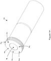
- the guide pin 20 further comprises a guide sleeve 28 at least substantially surrounding the fastener 24 and over which the caliper 16 slides.
- the guide sleeve is a hollow, thin walled tube.
- the outer surface of the sleeve may be coated with PTFE or any other suitable material to aid the sliding action of the caliper along the guide pin.
- the guide sleeve comprises a main body 30, a first end 32, a second end 34 and a bore hole 36 extending from the first end to the second end to receive the fastener.
- Each guide assembly comprises a sealing boot 38 to shroud the joint between the brake carrier 10 and the guide sleeve 28.
- the bore 22 disposed in the caliper to receive the guide pin is an elongate hole extending from a first side (inboard) to the second side (outboard) of the caliper 16.
- the disc brake of the present invention comprises a rotational fixing to rotationally engage the guide sleeve 28 and the brake carrier 10 and thereby substantially restrict undesirable rotation of the guide sleeve about its longitudinal axis.
- the rotational fixing is also configured to translationally engage the guide sleeve 28 and the brake carrier 10 and thereby substantially restrict translation movement of the guide sleeve relative to the brake carrier.
- the rotational fixing By translationally engaging the guide sleeve and the brake carrier, the rotational fixing helpfully substantially impedes undesirable lateral translational movement of the guide sleeve in the circumferential direction X and perpendicular translational movement of the guide sleeve in the tangential direction Y.
- Circumferential direction X is perpendicular to the axial direction A, perpendicular to the tangential direction Y and parallel to the longitudinal axis of the disc brake.
- Tangential direction Y is tangential to a circle describe by the rotation of the rotor 14, perpendicular to the axial direction A, perpendicular to the longitudinal axis of the disc brake and parallel to the direction in which the brake pads 12a, 12b are inserted or removed from the brake carrier 10.
- the disc brake may comprise one or more rotational fixings to engage the guide sleeve of each guide pin and brake carrier.
- the disc brake comprises three rotational fixings to restrict the movement of each guide pin.
- the rotational fixings are the same type.
- the rotational fixing for the disc brake comprises a sleeve portion of the guide sleeve, a receiving portion of the brake carrier for receiving the sleeve portion and an inter-connection to engage the sleeve portion and receiving portion when the sleeve portion is received in the receiving portion.
- the sleeve portion may comprise an end portion of the guide sleeve, a circumferential flange or rim of the guide sleeve.
- the sleeve portion of the guide sleeve is a circumferential flange 40 arranged at the first end 32 of the guide sleeve.
- the flange 40 has a substantially circular cross-sectional profile defined by a circular outer edge 42 and a substantially flat flange face 44.
- the guide sleeve is mounted on the brake carrier when the sleeve portion is received by the receiving portion.
- the receiving portion of the brake carrier may comprise a receiving face against which the sleeve portion is located when the sleeve portion is received by the receiving portion.
- the receiving portion comprises a recess 46 formed on the inboard side of the brake carrier into which the flange 40 of the guide sleeve can be fitted.
- the recess 46 has a circular inner edge 48 and a substantially flat, rear recess face 50.
- the circular inner edge 48 defines the cross-sectional profile of the receiving portion.
- the recess face 50 defines the receiving surface against which the flange face 44 abuts when it is received in the recess.
- the recess face 50 is deformable.
- the configuration of the recess 46 compliments the configuration of the flange 40 of the guide sleeve so to help further limit translational movement of the flange when the guide pin is subjected to dynamic loads.
- the bore 26 for receiving the fastener is located in the recess 46.
- the bore 26 may be centrally located or eccentrically located in the recess. In the embodiment shown in Figures 1 to 7 , the opening of the bore 26 is centrally arranged in the recess face 50.
- the recess may be manufactured with the desired cross-sectional profile using any conventional cutting, milling or machining techniques.
- the bore may be manufactured by any conventional drilling techniques.
- the inter-connection may comprise any suitable means to inter-lock the sleeve portion and receiving portion, when the sleeve portion is received in the receiving portion, so as to inhibit movement of the guide sleeve relative to the brake carrier.
- the inter-connection may comprise a connector co-locatable in a first cavity of the sleeve portion and a second cavity in the receiving potion when the sleeve portion is received in the receiving portion.
- the connector may have a cylinder, cuboid, sphere, ovoid, ellipsoid or any other suitably shaped body.
- each inter-connection comprises a ball bearing connector 52, a first semi-circular cavity 54 formed in the flange face 44 of the flange to receive a first sector of the ball bearing and a second semi-circular cavity 56 formed in the recess face 50 to receive a second sector of the ball bearing.
- the ball bearing connector 52, first semi-circular cavity 54 and second semi-circular cavity 56 are configured to form interference fit/press fit connections.
- the first cavity 54 is pre-formed prior to assembling the rotational fixing.
- the recess face 50 is deformable and the second cavity 56 is formed during assembly of rotational fixing to receive the second sector of the ball bearing connector.
- the ball bearing connectors 52 are initially fitted in the first semi-circular cavities 54 of the flange such that they protrude from the flange face 44 of the flange.
- the flange 40 with the protruding ball bearing connectors 52 is then located in the recess 46 such that the flange face 44 with the protruding ball bearing connectors 52 abuts the recess face 50.
- the fastener 24 is then extended through the bore hole 26 of the guide sleeve and it is screwed into the bore 26 of the brake carrier. Under the screwing action, the ball bearing connectors 52 are pushed against the recess face 50.
- the recess face 50 deforms to create second cavities which receive the second sector of the ball bearing connectors.
- the ball bearings connectors 52 are now co-located in both the first cavities and second cavities and the co-located ball bearings 52 form a rotational and translational engagement between the flange and the recess. Sealing boots 38 are fitted to the guide sleeves 28.
- the guide pin 20 When attached to the brake carrier 10, the guide pin 20 extends in an axial direction A from the brake carrier. Due to the configuration of the inter-connection and orientation of the cavities, the co-located ball bearings extend in the axial direction A between the guide sleeve and the brake carrier.
- the caliper 16 will be mounted on the guide pin by locating the guide pin in the caliper bore 22 and sliding the caliper along the guide sleeve.
- the disc brake depicted in Figure 1 can be actuated.
- An air actuator (not shown) is provided to move the inboard brake pad 12a into frictional contact with the rotor 14.
- the inboard brake pad 12a is pushed towards and contacts the rotor, the caliper slides inboard along the guide pin.
- the outboard brake pad 12b moves the outboard brake pad 12b towards the rotor.
- the rotor becomes clamped between the inboard and outboard brake pads and the rotation of the rotor is frictionally inhibited.
- the rotational fixing not only restricts undesirable rotation but also helps to properly align the guide sleeve relative to the brake carrier during assembly. If the flange and recess are not properly aligned, the guide sleeve will not extend in the correct direction from the brake carrier and the ball bearings may not form an engagement. As a result, an operator will not be able to mount the caliper on the guide pin. Therefore, the rotational fixing usefully protects the disk brake from operator assembly error.
- the receiving face of the receiving portion is a surface region of the inboard surface of the brake carrier.
- the receiving face surface region is substantially flush with the inboard surface.
- the second cavities may be pre-formed to form an interference or press-fit connection with the balls bearings, when the sleeve portion is received in the receiving portion and the first cavities and second cavities are aligned.
- the receiving face may be deformable as the ball bearings are co-located in the pre-formed second cavities to enhance the engaging connection.
- the first cavities and second cavities may be formed in side wall portions of the flange and recess such that when the ball bearings are co-located in the cavities, the ball bearings extend in a radial direction between the sleeve portion of the guide sleeve and receiving portion of the brake carrier.
- the radial direction is perpendicular to the axial direction A.
- the inter-connection may comprises a pin connector, a first cavity disposed in the sleeve portion to receive a first end of the pin connector and a second cavity disposed in the receiving portion to receive a second end of the pin connector.
- the inter-connection may additionally or alternatively comprise a protrusion integrally formed and extending from the sleeve portion or receiving portion and an indent formed in the corresponding portion to receive the protrusion.
- the inter-connection may comprise one or more blades or teeth extending in an axial direction A from the sleeve portion into corresponding indents in the brake carrier.
- the rotational fixing may further comprise a friction enhancer to enhance the frictional engagement between the sleeve portion and receiving portion and thereby further limit the rotation and/or translation of the guide sleeve with respect to the brake carrier.
- the friction enhancer may comprise a knurled surface formed on the sleeve portion to enhance the frictional grip of the sleeve portion with the receiving portion.
- the knurled surface may be arranged on an outer surface or outer edge of the sleeve portion.
Claims (13)
- Frein à disque (1), comprenant :un support de frein (10) ;un étrier (16) ;au moins une goupille de guidage (20) comprenant un manchon de guidage (28) ; etune partie de réception du support de frein (10) pour recevoir le manchon de guidage ; caractérisé parun élément de raccordement mutuel pour mettre en prise le manchon de guidage et la partie de réception afin de restreindre la rotation du manchon de guidage (28) relativement au support de frein (10), lorsque le manchon de guidage est reçu par la partie de réception, dans lequel la goupille de guidage (20) comprend en outre un élément de fixation de guidage (24) pour fixer la goupille de guidage (20) au support de frein (10), et le frein à disque (1) comprend en outre un alésage (26) formé dans le support de frein (10) pour recevoir l'élément de fixation de guidage (24), dans lequel l'alésage (26) est agencé de façon excentrique dans la partie de réception du support de frein (10).
- Frein à disque (1) selon la revendication 1, dans lequel l'élément de fixation de guidage (24) est configuré pour s'étendre à travers le manchon et l'alésage (26) est agencé dans la partie de réception du support de frein (10).
- Frein à disque (1) selon la revendication 1 ou la revendication 2, dans lequel l'élément de fixation de guidage (24) est un boulon de guidage.
- Frein à disque (1) selon la revendication 3, dans lequel le boulon de guidage est un boulon fileté et l'alésage (26) disposé dans le support de frein (10) a un alésage fileté complémentaire (26).
- Frein à disque (1) selon l'une quelconque des revendications 2 à 4, dans lequel l'élément de fixation de guidage (24) est l'élément de raccordement mutuel qui met en prise le manchon de guidage et la partie de réception.
- Frein à disque (1) selon la revendication 5, dans lequel l'élément de raccordement mutuel comprend :une saillie s'étendant à partir du manchon de guidage ou de la partie de réception ; etun renfoncement formé dans la partie correspondante et dans lequel la saillie peut être située lorsque le manchon de guidage est reçu par la partie de réception et la saillie et le renfoncement sont alignés.
- Frein à disque (1) selon la revendication 6, dans lequel l'élément de raccordement mutuel est configuré pour mettre en prise le manchon de guidage et la partie de réception afin de restreindre la translation du manchon de guidage (28) relativement au support de frein (10), lorsque le manchon de guidage est reçu par la partie de réception.
- Frein à disque (1) selon la revendication 6 ou la revendication 7, dans lequel le manchon de guidage comprend une partie première extrémité du manchon de guidage (28), ou un rebord à la première extrémité (32) du manchon de guidage (28), ou une bride (40) agencée à une première extrémité (32) du manchon de guidage (28).
- Frein à disque (1) selon l'une quelconque des revendications 6 à 8, dans lequel la partie de réception comprend une face de réception, optionnellement dans lequel la face de réception est une région de surface d'une surface intérieure du support de frein (10) et la face de réception est sensiblement au même niveau que la surface intérieure.
- Frein à disque (1) selon l'une quelconque des revendications 6 à 9, dans lequel la partie de réception comprend un évidement formé dans le support de frein (10) dans lequel le manchon de guidage est reçu lorsque le manchon de guidage est reçu par la partie de réception afin de restreindre la translation du manchon de guidage (28) relativement au support de frein (10), la face de réception étant disposée dans l'évidement.
- Frein à disque (1) selon l'une quelconque des revendications 6 à 10, dans lequel la saillie comprend une lame ou dent s'étendant vers l'extérieur à partir du manchon de guidage ou de la partie de réception.
- Frein à disque (1) selon l'une quelconque des revendications 6 à 11, dans lequel le renfoncement est un renfoncement préformé, formé dans la partie correspondante avant que le manchon de guidage soit reçu par la partie d'évidement et la saillie soit reçue dans le renfoncement.
- Frein à disque (1) selon l'une quelconque des revendications 6 à 12, dans lequel la partie de réception est déformable, la saillie est une saillie s'étendant à partir du manchon de guidage, et le renfoncement est un renfoncement formable dans la partie de réception, formé lorsque le manchon de guidage est reçu par la partie de réception et la saillie est poussée contre la partie de réception déformable.
Applications Claiming Priority (3)
| Application Number | Priority Date | Filing Date | Title |
|---|---|---|---|
| EP15170690.0A EP3101301B2 (fr) | 2015-06-04 | 2015-06-04 | Ensemble de guide |
| EP18196631.8A EP3441636B1 (fr) | 2015-06-04 | 2016-06-06 | Jonction antirotation d'un boulon de frein a disque et métode relative |
| EP16173201.1A EP3133312B1 (fr) | 2015-06-04 | 2016-06-06 | Fixation de rotation pour une broche de guidage d'un frein à disque et procédé associé |
Related Parent Applications (2)
| Application Number | Title | Priority Date | Filing Date |
|---|---|---|---|
| EP16173201.1A Division EP3133312B1 (fr) | 2015-06-04 | 2016-06-06 | Fixation de rotation pour une broche de guidage d'un frein à disque et procédé associé |
| EP18196631.8A Division EP3441636B1 (fr) | 2015-06-04 | 2016-06-06 | Jonction antirotation d'un boulon de frein a disque et métode relative |
Publications (2)
| Publication Number | Publication Date |
|---|---|
| EP3617542A1 EP3617542A1 (fr) | 2020-03-04 |
| EP3617542B1 true EP3617542B1 (fr) | 2022-02-09 |
Family
ID=53284118
Family Applications (5)
| Application Number | Title | Priority Date | Filing Date |
|---|---|---|---|
| EP15170690.0A Active EP3101301B2 (fr) | 2015-06-04 | 2015-06-04 | Ensemble de guide |
| EP18184472.1A Active EP3415781B1 (fr) | 2015-06-04 | 2015-06-04 | Ensemble de guide |
| EP19204415.4A Active EP3617542B1 (fr) | 2015-06-04 | 2016-06-06 | Jonction antirotation d'un boulon de frein a disque |
| EP18196631.8A Active EP3441636B1 (fr) | 2015-06-04 | 2016-06-06 | Jonction antirotation d'un boulon de frein a disque et métode relative |
| EP16173201.1A Active EP3133312B1 (fr) | 2015-06-04 | 2016-06-06 | Fixation de rotation pour une broche de guidage d'un frein à disque et procédé associé |
Family Applications Before (2)
| Application Number | Title | Priority Date | Filing Date |
|---|---|---|---|
| EP15170690.0A Active EP3101301B2 (fr) | 2015-06-04 | 2015-06-04 | Ensemble de guide |
| EP18184472.1A Active EP3415781B1 (fr) | 2015-06-04 | 2015-06-04 | Ensemble de guide |
Family Applications After (2)
| Application Number | Title | Priority Date | Filing Date |
|---|---|---|---|
| EP18196631.8A Active EP3441636B1 (fr) | 2015-06-04 | 2016-06-06 | Jonction antirotation d'un boulon de frein a disque et métode relative |
| EP16173201.1A Active EP3133312B1 (fr) | 2015-06-04 | 2016-06-06 | Fixation de rotation pour une broche de guidage d'un frein à disque et procédé associé |
Country Status (2)
| Country | Link |
|---|---|
| US (4) | US10221904B2 (fr) |
| EP (5) | EP3101301B2 (fr) |
Families Citing this family (10)
| Publication number | Priority date | Publication date | Assignee | Title |
|---|---|---|---|---|
| EP3101301B2 (fr) * | 2015-06-04 | 2024-03-06 | Meritor Heavy Vehicle Braking Systems (UK) Limited | Ensemble de guide |
| CN108474424B (zh) * | 2015-11-05 | 2021-02-09 | 克诺尔商用车制动系统有限公司 | 用于商用车的盘式制动器 |
| EP3492768B1 (fr) | 2017-11-29 | 2021-02-24 | Meritor Heavy Vehicle Braking Systems (UK) Limited | Ensemble de guidage d'étrier |
| US11698115B2 (en) * | 2019-02-12 | 2023-07-11 | ZF Active Safety US Inc. | Sliding mechanism for guide pins of a disc brake assembly |
| EP3779226B1 (fr) * | 2019-08-16 | 2022-07-06 | Meritor Heavy Vehicle Braking Systems (UK) Limited | Ensemble de guidage pour frein à disque |
| EP3779225B1 (fr) | 2019-08-16 | 2022-11-16 | Meritor Heavy Vehicle Braking Systems (UK) Limited | Ensemble de guidage pour frein à disque |
| EP3779224B1 (fr) | 2019-08-16 | 2022-10-05 | Meritor Heavy Vehicle Braking Systems (UK) Limited | Montage pour une broche de guidage d'un frein à disque |
| EP3872360A1 (fr) * | 2020-02-28 | 2021-09-01 | Meritor Heavy Vehicle Braking Systems (UK) Limited | Ensemble de guidage d'étrier |
| CN111322325B (zh) * | 2020-04-07 | 2021-05-07 | 马鞍山博越精密机械有限公司 | 一种安装角度可调节的卡钳支架及生产工艺 |
| US11773928B2 (en) | 2020-12-14 | 2023-10-03 | Arvinmeritor Technology, Llc | Brake assembly having a guide pin assembly |
Citations (2)
| Publication number | Priority date | Publication date | Assignee | Title |
|---|---|---|---|---|
| EP0035946B1 (fr) * | 1980-03-10 | 1984-08-01 | The Bendix Corporation | Frein à disque à étrier coulissant |
| US20140116817A1 (en) * | 2012-11-01 | 2014-05-01 | Kelsey-Hayes Company | Guide Pin For Disc Brake Assembly And Disc Brake Assembly Including Such A Guide Pin |
Family Cites Families (36)
| Publication number | Priority date | Publication date | Assignee | Title |
|---|---|---|---|---|
| US2477969A (en) * | 1946-05-04 | 1949-08-02 | Mid Continent Metal Products C | Coupling |
| US2527871A (en) * | 1946-06-21 | 1950-10-31 | Harding F Bakewell | Toolholder |
| US3213658A (en) * | 1963-11-21 | 1965-10-26 | Buckbee Mears Co | Forming dome-shaped mesh |
| FR2142248A5 (fr) | 1971-06-18 | 1973-01-26 | Dba | |
| GB2027826B (en) | 1978-06-29 | 1982-07-28 | Lucas Industries Ltd | Disc brake assembly |
| US4244451A (en) * | 1979-03-26 | 1981-01-13 | The Bendix Corporation | Disc brake and pin assembly therefor |
| FR2469615A1 (fr) * | 1979-11-08 | 1981-05-22 | Dba | Frein a disque a etrier coulissant |
| US4393963A (en) * | 1980-09-26 | 1983-07-19 | The Bendix Corporation | Disc brake caliper support |
| US4596316A (en) * | 1984-02-10 | 1986-06-24 | Goodyear Aerospace Corporation | Electrically actuated aircraft brakes |
| GB2163225B (en) | 1984-08-18 | 1988-07-06 | Lucas Ind Plc | Improvements in self-energising disc brakes |
| US4762206A (en) * | 1985-11-15 | 1988-08-09 | Nippon Air Brake Co., Ltd. | Disc brake |
| DE3614211A1 (de) | 1986-04-26 | 1987-10-29 | Goldbeckbau Gmbh | Loesbare verbindung zwischen stahltraeger und stahlbeton-fertigelement |
| DE8633923U1 (fr) | 1986-12-18 | 1988-04-21 | Lucas Industries P.L.C., Birmingham, West Midlands, Gb | |
| JPH048927A (ja) * | 1990-04-26 | 1992-01-13 | Nissan Motor Co Ltd | フローティング形ディスクブレーキ |
| DE9115195U1 (fr) * | 1991-12-06 | 1992-02-06 | Lucas Industries P.L.C., Birmingham, West Midlands, Gb | |
| WO1994001963A1 (fr) * | 1992-07-08 | 1994-01-20 | Joseph Rozgonyi | Systeme de commande d'access a un telephone cellulaire et d'identification |
| US5439084A (en) * | 1992-07-10 | 1995-08-08 | Bendix Espana S.A. | Device for a guiding sliding caliper for a disk-brake |
| US5351583A (en) * | 1993-03-03 | 1994-10-04 | Patcore, Incorporated | Toothless ratchet, clutch, and mechanisms to eliminate backlash |
| DE9305631U1 (de) * | 1993-04-15 | 1994-08-25 | Lucas Ind Plc | Schwimmsattelbremse, insbesondere Schwimmsattel-Teilbelag-Scheibenbremse |
| FR2705748B1 (fr) * | 1993-05-25 | 1995-07-07 | Alliedsignal Europ Services | Frein à disque à étrier coulissant. |
| KR100349530B1 (ko) | 2000-09-07 | 2002-08-21 | 주식회사 만도 | 차량용 디스크 브레이크의 가이드 로드 |
| WO2003025413A1 (fr) | 2001-09-18 | 2003-03-27 | Knorr-Bremse Systeme für Nutzfahrzeuge GmbH | Frein a disque destine notamment a un vehicule utilitaire |
| DE10150214B4 (de) | 2001-10-12 | 2020-10-29 | Knorr-Bremse Systeme für Nutzfahrzeuge GmbH | Scheibenbremse, insbesondere für ein Nutzfahrzeug |
| DE10311896A1 (de) * | 2003-03-18 | 2004-09-30 | Knorr-Bremse Systeme für Nutzfahrzeuge GmbH | Scheibenbremse, insbesondere für Nutzfahrzeuge |
| DE10327623B4 (de) | 2003-06-19 | 2006-07-13 | Mtu Aero Engines Gmbh | Fräsverfahren zur Fertigung von Bauteilen |
| FR2905155B1 (fr) | 2006-08-23 | 2009-03-27 | Bosch Gmbh Robert | Frein a disque comportant un axe dont une portee presente une section de profil non circulaire |
| US20080135352A1 (en) | 2006-12-12 | 2008-06-12 | Bendix Spicer Foundation Brake Llc | Brake caliper vertical mounting assembly joint arrangement |
| US8051958B1 (en) | 2007-02-16 | 2011-11-08 | Kelsey-Hayes Company | Guide pin for disc brake assembly and disc brake assembly including such a guide pin |
| DE102007053902A1 (de) * | 2007-11-09 | 2009-05-20 | Knorr-Bremse Systeme für Nutzfahrzeuge GmbH | Scheibenbremse für ein Nutzfahrzeug |
| EP2058717B1 (fr) | 2007-11-12 | 2011-07-20 | Siemens Aktiengesellschaft | Procédé et dispositif destinés au fonctionnement d'une machine-outil |
| DE102008021233A1 (de) | 2008-04-28 | 2009-10-29 | Rud Ketten Rieger & Dietz Gmbh U. Co. Kg | Förderkette mit gummielastischer Lagerung |
| EP2356349B1 (fr) * | 2008-11-13 | 2012-09-05 | Robert Bosch GmbH | Manchon pour étrier de frein à disque et frein à disque muni d'un tel manchon |
| DE102010020588A1 (de) | 2010-05-14 | 2011-11-17 | Wabco Radbremsen Gmbh | Scheibenbremse, insbesondere für Nutzfahrzeuge, und Dichtung einer solchen Scheibenbremse |
| DE102012014886A1 (de) | 2012-07-26 | 2014-01-30 | Knorr-Bremse Systeme für Nutzfahrzeuge GmbH | Zuspanneinrichtung einer Scheibenbremse für ein Nutzfahrzeug |
| WO2014071001A1 (fr) | 2012-11-01 | 2014-05-08 | Kelsey-Hayes Company | Tige de guidage pour ensemble frein à disque, ensemble frein à disque comprenant une telle tige de guidage et procédé de fabrication d'un ensemble frein à disque comprenant un telle tige de guidage |
| EP3101301B2 (fr) * | 2015-06-04 | 2024-03-06 | Meritor Heavy Vehicle Braking Systems (UK) Limited | Ensemble de guide |
-
2015
- 2015-06-04 EP EP15170690.0A patent/EP3101301B2/fr active Active
- 2015-06-04 EP EP18184472.1A patent/EP3415781B1/fr active Active
-
2016
- 2016-06-06 EP EP19204415.4A patent/EP3617542B1/fr active Active
- 2016-06-06 EP EP18196631.8A patent/EP3441636B1/fr active Active
- 2016-06-06 US US15/174,080 patent/US10221904B2/en active Active
- 2016-06-06 EP EP16173201.1A patent/EP3133312B1/fr active Active
- 2016-06-06 US US15/174,102 patent/US20160356326A1/en not_active Abandoned
-
2019
- 2019-03-01 US US16/290,237 patent/US20190195299A1/en not_active Abandoned
-
2020
- 2020-08-21 US US16/999,610 patent/US20200378457A1/en not_active Abandoned
Patent Citations (2)
| Publication number | Priority date | Publication date | Assignee | Title |
|---|---|---|---|---|
| EP0035946B1 (fr) * | 1980-03-10 | 1984-08-01 | The Bendix Corporation | Frein à disque à étrier coulissant |
| US20140116817A1 (en) * | 2012-11-01 | 2014-05-01 | Kelsey-Hayes Company | Guide Pin For Disc Brake Assembly And Disc Brake Assembly Including Such A Guide Pin |
Also Published As
| Publication number | Publication date |
|---|---|
| EP3415781A1 (fr) | 2018-12-19 |
| EP3133312A2 (fr) | 2017-02-22 |
| EP3101301B2 (fr) | 2024-03-06 |
| EP3101301A1 (fr) | 2016-12-07 |
| EP3415781B1 (fr) | 2020-04-22 |
| US20160356325A1 (en) | 2016-12-08 |
| EP3441636A1 (fr) | 2019-02-13 |
| EP3133312B1 (fr) | 2018-11-07 |
| US20200378457A1 (en) | 2020-12-03 |
| EP3617542A1 (fr) | 2020-03-04 |
| US20160356326A1 (en) | 2016-12-08 |
| EP3101301B1 (fr) | 2018-09-19 |
| US20190195299A1 (en) | 2019-06-27 |
| EP3133312A3 (fr) | 2017-03-22 |
| EP3441636B1 (fr) | 2019-10-23 |
| US10221904B2 (en) | 2019-03-05 |
Similar Documents
| Publication | Publication Date | Title |
|---|---|---|
| EP3617542B1 (fr) | Jonction antirotation d'un boulon de frein a disque | |
| US9180841B2 (en) | Disk brake | |
| EP3552839B1 (fr) | Assemblage de structure pour roue-pneu, rotor de frein et moyeu | |
| US11560929B2 (en) | Guide assembly for a disc brake | |
| US9994205B2 (en) | Axis of a land vehicle, land vehicle with such a suspension and disk brake and brake support of such land vehicle | |
| CN111480020A (zh) | 制动盘-轮毂连接装置 | |
| US10781872B2 (en) | Floating collar and one-piece guide pin and bolt assembly | |
| US11603895B2 (en) | Mounting for a guide pin of a disc brake | |
| CA3073578A1 (fr) | Ensemble rotor de frein a disque | |
| US10605317B2 (en) | Fixing for a brake carrier and a mount for a disc brake and method thereof | |
| JP4532299B2 (ja) | ディスクブレーキ | |
| GB2551855B (en) | Sliding caliper disc brake | |
| EP3772599A1 (fr) | Étrier de frein pour un frein de véhicule et procédé d'assemblage d'un étrier de frein | |
| JP4432266B2 (ja) | ディスクブレーキ | |
| JP2009264477A (ja) | ディスクブレーキ | |
| JP2005257055A (ja) | ディスクブレーキ | |
| JPH1026155A (ja) | ディスクブレーキのアウタパッド支持構造 |
Legal Events
| Date | Code | Title | Description |
|---|---|---|---|
| PUAI | Public reference made under article 153(3) epc to a published international application that has entered the european phase |
Free format text: ORIGINAL CODE: 0009012 |
|
| STAA | Information on the status of an ep patent application or granted ep patent |
Free format text: STATUS: THE APPLICATION HAS BEEN PUBLISHED |
|
| AC | Divisional application: reference to earlier application |
Ref document number: 3133312 Country of ref document: EP Kind code of ref document: P Ref document number: 3441636 Country of ref document: EP Kind code of ref document: P |
|
| AK | Designated contracting states |
Kind code of ref document: A1 Designated state(s): AL AT BE BG CH CY CZ DE DK EE ES FI FR GB GR HR HU IE IS IT LI LT LU LV MC MK MT NL NO PL PT RO RS SE SI SK SM TR |
|
| STAA | Information on the status of an ep patent application or granted ep patent |
Free format text: STATUS: REQUEST FOR EXAMINATION WAS MADE |
|
| 17P | Request for examination filed |
Effective date: 20200831 |
|
| GRAP | Despatch of communication of intention to grant a patent |
Free format text: ORIGINAL CODE: EPIDOSNIGR1 |
|
| RBV | Designated contracting states (corrected) |
Designated state(s): AL AT BE BG CH CY CZ DE DK EE ES FI FR GB GR HR HU IE IS IT LI LT LU LV MC MK MT NL NO PL PT RO RS SE SI SK SM TR |
|
| STAA | Information on the status of an ep patent application or granted ep patent |
Free format text: STATUS: GRANT OF PATENT IS INTENDED |
|
| INTG | Intention to grant announced |
Effective date: 20201008 |
|
| GRAJ | Information related to disapproval of communication of intention to grant by the applicant or resumption of examination proceedings by the epo deleted |
Free format text: ORIGINAL CODE: EPIDOSDIGR1 |
|
| STAA | Information on the status of an ep patent application or granted ep patent |
Free format text: STATUS: REQUEST FOR EXAMINATION WAS MADE |
|
| INTC | Intention to grant announced (deleted) | ||
| GRAP | Despatch of communication of intention to grant a patent |
Free format text: ORIGINAL CODE: EPIDOSNIGR1 |
|
| GRAJ | Information related to disapproval of communication of intention to grant by the applicant or resumption of examination proceedings by the epo deleted |
Free format text: ORIGINAL CODE: EPIDOSDIGR1 |
|
| GRAJ | Information related to disapproval of communication of intention to grant by the applicant or resumption of examination proceedings by the epo deleted |
Free format text: ORIGINAL CODE: EPIDOSDIGR1 |
|
| GRAP | Despatch of communication of intention to grant a patent |
Free format text: ORIGINAL CODE: EPIDOSNIGR1 |
|
| GRAP | Despatch of communication of intention to grant a patent |
Free format text: ORIGINAL CODE: EPIDOSNIGR1 |
|
| STAA | Information on the status of an ep patent application or granted ep patent |
Free format text: STATUS: GRANT OF PATENT IS INTENDED |
|
| INTG | Intention to grant announced |
Effective date: 20210503 |
|
| INTC | Intention to grant announced (deleted) | ||
| INTG | Intention to grant announced |
Effective date: 20210511 |
|
| INTC | Intention to grant announced (deleted) | ||
| INTG | Intention to grant announced |
Effective date: 20210526 |
|
| GRAJ | Information related to disapproval of communication of intention to grant by the applicant or resumption of examination proceedings by the epo deleted |
Free format text: ORIGINAL CODE: EPIDOSDIGR1 |
|
| STAA | Information on the status of an ep patent application or granted ep patent |
Free format text: STATUS: REQUEST FOR EXAMINATION WAS MADE |
|
| GRAP | Despatch of communication of intention to grant a patent |
Free format text: ORIGINAL CODE: EPIDOSNIGR1 |
|
| STAA | Information on the status of an ep patent application or granted ep patent |
Free format text: STATUS: GRANT OF PATENT IS INTENDED |
|
| INTC | Intention to grant announced (deleted) | ||
| INTG | Intention to grant announced |
Effective date: 20210928 |
|
| GRAS | Grant fee paid |
Free format text: ORIGINAL CODE: EPIDOSNIGR3 |
|
| GRAA | (expected) grant |
Free format text: ORIGINAL CODE: 0009210 |
|
| STAA | Information on the status of an ep patent application or granted ep patent |
Free format text: STATUS: THE PATENT HAS BEEN GRANTED |
|
| AC | Divisional application: reference to earlier application |
Ref document number: 3133312 Country of ref document: EP Kind code of ref document: P Ref document number: 3441636 Country of ref document: EP Kind code of ref document: P |
|
| AK | Designated contracting states |
Kind code of ref document: B1 Designated state(s): AL AT BE BG CH CY CZ DE DK EE ES FI FR GB GR HR HU IE IS IT LI LT LU LV MC MK MT NL NO PL PT RO RS SE SI SK SM TR |
|
| REG | Reference to a national code |
Ref country code: GB Ref legal event code: FG4D |
|
| REG | Reference to a national code |
Ref country code: CH Ref legal event code: EP Ref country code: AT Ref legal event code: REF Ref document number: 1467692 Country of ref document: AT Kind code of ref document: T Effective date: 20220215 |
|
| REG | Reference to a national code |
Ref country code: DE Ref legal event code: R096 Ref document number: 602016069095 Country of ref document: DE |
|
| REG | Reference to a national code |
Ref country code: IE Ref legal event code: FG4D |
|
| REG | Reference to a national code |
Ref country code: LT Ref legal event code: MG9D |
|
| REG | Reference to a national code |
Ref country code: NL Ref legal event code: MP Effective date: 20220209 |
|
| REG | Reference to a national code |
Ref country code: AT Ref legal event code: MK05 Ref document number: 1467692 Country of ref document: AT Kind code of ref document: T Effective date: 20220209 |
|
| PG25 | Lapsed in a contracting state [announced via postgrant information from national office to epo] |
Ref country code: SE Free format text: LAPSE BECAUSE OF FAILURE TO SUBMIT A TRANSLATION OF THE DESCRIPTION OR TO PAY THE FEE WITHIN THE PRESCRIBED TIME-LIMIT Effective date: 20220209 Ref country code: RS Free format text: LAPSE BECAUSE OF FAILURE TO SUBMIT A TRANSLATION OF THE DESCRIPTION OR TO PAY THE FEE WITHIN THE PRESCRIBED TIME-LIMIT Effective date: 20220209 Ref country code: PT Free format text: LAPSE BECAUSE OF FAILURE TO SUBMIT A TRANSLATION OF THE DESCRIPTION OR TO PAY THE FEE WITHIN THE PRESCRIBED TIME-LIMIT Effective date: 20220609 Ref country code: NO Free format text: LAPSE BECAUSE OF FAILURE TO SUBMIT A TRANSLATION OF THE DESCRIPTION OR TO PAY THE FEE WITHIN THE PRESCRIBED TIME-LIMIT Effective date: 20220509 Ref country code: NL Free format text: LAPSE BECAUSE OF FAILURE TO SUBMIT A TRANSLATION OF THE DESCRIPTION OR TO PAY THE FEE WITHIN THE PRESCRIBED TIME-LIMIT Effective date: 20220209 Ref country code: LT Free format text: LAPSE BECAUSE OF FAILURE TO SUBMIT A TRANSLATION OF THE DESCRIPTION OR TO PAY THE FEE WITHIN THE PRESCRIBED TIME-LIMIT Effective date: 20220209 Ref country code: HR Free format text: LAPSE BECAUSE OF FAILURE TO SUBMIT A TRANSLATION OF THE DESCRIPTION OR TO PAY THE FEE WITHIN THE PRESCRIBED TIME-LIMIT Effective date: 20220209 Ref country code: ES Free format text: LAPSE BECAUSE OF FAILURE TO SUBMIT A TRANSLATION OF THE DESCRIPTION OR TO PAY THE FEE WITHIN THE PRESCRIBED TIME-LIMIT Effective date: 20220209 Ref country code: BG Free format text: LAPSE BECAUSE OF FAILURE TO SUBMIT A TRANSLATION OF THE DESCRIPTION OR TO PAY THE FEE WITHIN THE PRESCRIBED TIME-LIMIT Effective date: 20220509 |
|
| PG25 | Lapsed in a contracting state [announced via postgrant information from national office to epo] |
Ref country code: PL Free format text: LAPSE BECAUSE OF FAILURE TO SUBMIT A TRANSLATION OF THE DESCRIPTION OR TO PAY THE FEE WITHIN THE PRESCRIBED TIME-LIMIT Effective date: 20220209 Ref country code: LV Free format text: LAPSE BECAUSE OF FAILURE TO SUBMIT A TRANSLATION OF THE DESCRIPTION OR TO PAY THE FEE WITHIN THE PRESCRIBED TIME-LIMIT Effective date: 20220209 Ref country code: GR Free format text: LAPSE BECAUSE OF FAILURE TO SUBMIT A TRANSLATION OF THE DESCRIPTION OR TO PAY THE FEE WITHIN THE PRESCRIBED TIME-LIMIT Effective date: 20220510 Ref country code: FI Free format text: LAPSE BECAUSE OF FAILURE TO SUBMIT A TRANSLATION OF THE DESCRIPTION OR TO PAY THE FEE WITHIN THE PRESCRIBED TIME-LIMIT Effective date: 20220209 Ref country code: AT Free format text: LAPSE BECAUSE OF FAILURE TO SUBMIT A TRANSLATION OF THE DESCRIPTION OR TO PAY THE FEE WITHIN THE PRESCRIBED TIME-LIMIT Effective date: 20220209 |
|
| PG25 | Lapsed in a contracting state [announced via postgrant information from national office to epo] |
Ref country code: IS Free format text: LAPSE BECAUSE OF FAILURE TO SUBMIT A TRANSLATION OF THE DESCRIPTION OR TO PAY THE FEE WITHIN THE PRESCRIBED TIME-LIMIT Effective date: 20220609 |
|
| PG25 | Lapsed in a contracting state [announced via postgrant information from national office to epo] |
Ref country code: SM Free format text: LAPSE BECAUSE OF FAILURE TO SUBMIT A TRANSLATION OF THE DESCRIPTION OR TO PAY THE FEE WITHIN THE PRESCRIBED TIME-LIMIT Effective date: 20220209 Ref country code: SK Free format text: LAPSE BECAUSE OF FAILURE TO SUBMIT A TRANSLATION OF THE DESCRIPTION OR TO PAY THE FEE WITHIN THE PRESCRIBED TIME-LIMIT Effective date: 20220209 Ref country code: RO Free format text: LAPSE BECAUSE OF FAILURE TO SUBMIT A TRANSLATION OF THE DESCRIPTION OR TO PAY THE FEE WITHIN THE PRESCRIBED TIME-LIMIT Effective date: 20220209 Ref country code: EE Free format text: LAPSE BECAUSE OF FAILURE TO SUBMIT A TRANSLATION OF THE DESCRIPTION OR TO PAY THE FEE WITHIN THE PRESCRIBED TIME-LIMIT Effective date: 20220209 Ref country code: DK Free format text: LAPSE BECAUSE OF FAILURE TO SUBMIT A TRANSLATION OF THE DESCRIPTION OR TO PAY THE FEE WITHIN THE PRESCRIBED TIME-LIMIT Effective date: 20220209 Ref country code: CZ Free format text: LAPSE BECAUSE OF FAILURE TO SUBMIT A TRANSLATION OF THE DESCRIPTION OR TO PAY THE FEE WITHIN THE PRESCRIBED TIME-LIMIT Effective date: 20220209 |
|
| REG | Reference to a national code |
Ref country code: DE Ref legal event code: R097 Ref document number: 602016069095 Country of ref document: DE |
|
| PG25 | Lapsed in a contracting state [announced via postgrant information from national office to epo] |
Ref country code: AL Free format text: LAPSE BECAUSE OF FAILURE TO SUBMIT A TRANSLATION OF THE DESCRIPTION OR TO PAY THE FEE WITHIN THE PRESCRIBED TIME-LIMIT Effective date: 20220209 |
|
| PLBE | No opposition filed within time limit |
Free format text: ORIGINAL CODE: 0009261 |
|
| STAA | Information on the status of an ep patent application or granted ep patent |
Free format text: STATUS: NO OPPOSITION FILED WITHIN TIME LIMIT |
|
| 26N | No opposition filed |
Effective date: 20221110 |
|
| PG25 | Lapsed in a contracting state [announced via postgrant information from national office to epo] |
Ref country code: MC Free format text: LAPSE BECAUSE OF FAILURE TO SUBMIT A TRANSLATION OF THE DESCRIPTION OR TO PAY THE FEE WITHIN THE PRESCRIBED TIME-LIMIT Effective date: 20220209 |
|
| REG | Reference to a national code |
Ref country code: CH Ref legal event code: PL |
|
| REG | Reference to a national code |
Ref country code: BE Ref legal event code: MM Effective date: 20220630 |
|
| PG25 | Lapsed in a contracting state [announced via postgrant information from national office to epo] |
Ref country code: SI Free format text: LAPSE BECAUSE OF FAILURE TO SUBMIT A TRANSLATION OF THE DESCRIPTION OR TO PAY THE FEE WITHIN THE PRESCRIBED TIME-LIMIT Effective date: 20220209 |
|
| GBPC | Gb: european patent ceased through non-payment of renewal fee |
Effective date: 20220606 |
|
| PG25 | Lapsed in a contracting state [announced via postgrant information from national office to epo] |
Ref country code: LU Free format text: LAPSE BECAUSE OF NON-PAYMENT OF DUE FEES Effective date: 20220606 Ref country code: LI Free format text: LAPSE BECAUSE OF NON-PAYMENT OF DUE FEES Effective date: 20220630 Ref country code: IE Free format text: LAPSE BECAUSE OF NON-PAYMENT OF DUE FEES Effective date: 20220606 Ref country code: FR Free format text: LAPSE BECAUSE OF NON-PAYMENT OF DUE FEES Effective date: 20220630 Ref country code: CH Free format text: LAPSE BECAUSE OF NON-PAYMENT OF DUE FEES Effective date: 20220630 |
|
| PG25 | Lapsed in a contracting state [announced via postgrant information from national office to epo] |
Ref country code: GB Free format text: LAPSE BECAUSE OF NON-PAYMENT OF DUE FEES Effective date: 20220606 Ref country code: BE Free format text: LAPSE BECAUSE OF NON-PAYMENT OF DUE FEES Effective date: 20220630 |
|
| P01 | Opt-out of the competence of the unified patent court (upc) registered |
Effective date: 20230531 |
|
| PG25 | Lapsed in a contracting state [announced via postgrant information from national office to epo] |
Ref country code: IT Free format text: LAPSE BECAUSE OF FAILURE TO SUBMIT A TRANSLATION OF THE DESCRIPTION OR TO PAY THE FEE WITHIN THE PRESCRIBED TIME-LIMIT Effective date: 20220209 |
|
| PGFP | Annual fee paid to national office [announced via postgrant information from national office to epo] |
Ref country code: DE Payment date: 20230626 Year of fee payment: 8 |
|
| PG25 | Lapsed in a contracting state [announced via postgrant information from national office to epo] |
Ref country code: MK Free format text: LAPSE BECAUSE OF FAILURE TO SUBMIT A TRANSLATION OF THE DESCRIPTION OR TO PAY THE FEE WITHIN THE PRESCRIBED TIME-LIMIT Effective date: 20220209 Ref country code: CY Free format text: LAPSE BECAUSE OF FAILURE TO SUBMIT A TRANSLATION OF THE DESCRIPTION OR TO PAY THE FEE WITHIN THE PRESCRIBED TIME-LIMIT Effective date: 20220209 |