EP3617542B1 - Rotational fixing for a guide pin of a disc brake - Google Patents
Rotational fixing for a guide pin of a disc brake Download PDFInfo
- Publication number
- EP3617542B1 EP3617542B1 EP19204415.4A EP19204415A EP3617542B1 EP 3617542 B1 EP3617542 B1 EP 3617542B1 EP 19204415 A EP19204415 A EP 19204415A EP 3617542 B1 EP3617542 B1 EP 3617542B1
- Authority
- EP
- European Patent Office
- Prior art keywords
- guide sleeve
- receiving portion
- guide
- brake
- brake carrier
- Prior art date
- Legal status (The legal status is an assumption and is not a legal conclusion. Google has not performed a legal analysis and makes no representation as to the accuracy of the status listed.)
- Active
Links
Images


Classifications
-
- F—MECHANICAL ENGINEERING; LIGHTING; HEATING; WEAPONS; BLASTING
- F16—ENGINEERING ELEMENTS AND UNITS; GENERAL MEASURES FOR PRODUCING AND MAINTAINING EFFECTIVE FUNCTIONING OF MACHINES OR INSTALLATIONS; THERMAL INSULATION IN GENERAL
- F16D—COUPLINGS FOR TRANSMITTING ROTATION; CLUTCHES; BRAKES
- F16D55/00—Brakes with substantially-radial braking surfaces pressed together in axial direction, e.g. disc brakes
- F16D55/02—Brakes with substantially-radial braking surfaces pressed together in axial direction, e.g. disc brakes with axially-movable discs or pads pressed against axially-located rotating members
- F16D55/22—Brakes with substantially-radial braking surfaces pressed together in axial direction, e.g. disc brakes with axially-movable discs or pads pressed against axially-located rotating members by clamping an axially-located rotating disc between movable braking members, e.g. movable brake discs or brake pads
- F16D55/224—Brakes with substantially-radial braking surfaces pressed together in axial direction, e.g. disc brakes with axially-movable discs or pads pressed against axially-located rotating members by clamping an axially-located rotating disc between movable braking members, e.g. movable brake discs or brake pads with a common actuating member for the braking members
- F16D55/225—Brakes with substantially-radial braking surfaces pressed together in axial direction, e.g. disc brakes with axially-movable discs or pads pressed against axially-located rotating members by clamping an axially-located rotating disc between movable braking members, e.g. movable brake discs or brake pads with a common actuating member for the braking members the braking members being brake pads
- F16D55/226—Brakes with substantially-radial braking surfaces pressed together in axial direction, e.g. disc brakes with axially-movable discs or pads pressed against axially-located rotating members by clamping an axially-located rotating disc between movable braking members, e.g. movable brake discs or brake pads with a common actuating member for the braking members the braking members being brake pads in which the common actuating member is moved axially, e.g. floating caliper disc brakes
- F16D55/2265—Brakes with substantially-radial braking surfaces pressed together in axial direction, e.g. disc brakes with axially-movable discs or pads pressed against axially-located rotating members by clamping an axially-located rotating disc between movable braking members, e.g. movable brake discs or brake pads with a common actuating member for the braking members the braking members being brake pads in which the common actuating member is moved axially, e.g. floating caliper disc brakes the axial movement being guided by one or more pins engaging bores in the brake support or the brake housing
- F16D55/22655—Constructional details of guide pins
-
- F—MECHANICAL ENGINEERING; LIGHTING; HEATING; WEAPONS; BLASTING
- F16—ENGINEERING ELEMENTS AND UNITS; GENERAL MEASURES FOR PRODUCING AND MAINTAINING EFFECTIVE FUNCTIONING OF MACHINES OR INSTALLATIONS; THERMAL INSULATION IN GENERAL
- F16D—COUPLINGS FOR TRANSMITTING ROTATION; CLUTCHES; BRAKES
- F16D55/00—Brakes with substantially-radial braking surfaces pressed together in axial direction, e.g. disc brakes
- F16D55/02—Brakes with substantially-radial braking surfaces pressed together in axial direction, e.g. disc brakes with axially-movable discs or pads pressed against axially-located rotating members
- F16D55/22—Brakes with substantially-radial braking surfaces pressed together in axial direction, e.g. disc brakes with axially-movable discs or pads pressed against axially-located rotating members by clamping an axially-located rotating disc between movable braking members, e.g. movable brake discs or brake pads
- F16D55/224—Brakes with substantially-radial braking surfaces pressed together in axial direction, e.g. disc brakes with axially-movable discs or pads pressed against axially-located rotating members by clamping an axially-located rotating disc between movable braking members, e.g. movable brake discs or brake pads with a common actuating member for the braking members
- F16D55/225—Brakes with substantially-radial braking surfaces pressed together in axial direction, e.g. disc brakes with axially-movable discs or pads pressed against axially-located rotating members by clamping an axially-located rotating disc between movable braking members, e.g. movable brake discs or brake pads with a common actuating member for the braking members the braking members being brake pads
- F16D55/226—Brakes with substantially-radial braking surfaces pressed together in axial direction, e.g. disc brakes with axially-movable discs or pads pressed against axially-located rotating members by clamping an axially-located rotating disc between movable braking members, e.g. movable brake discs or brake pads with a common actuating member for the braking members the braking members being brake pads in which the common actuating member is moved axially, e.g. floating caliper disc brakes
- F16D55/2265—Brakes with substantially-radial braking surfaces pressed together in axial direction, e.g. disc brakes with axially-movable discs or pads pressed against axially-located rotating members by clamping an axially-located rotating disc between movable braking members, e.g. movable brake discs or brake pads with a common actuating member for the braking members the braking members being brake pads in which the common actuating member is moved axially, e.g. floating caliper disc brakes the axial movement being guided by one or more pins engaging bores in the brake support or the brake housing
- F16D55/227—Brakes with substantially-radial braking surfaces pressed together in axial direction, e.g. disc brakes with axially-movable discs or pads pressed against axially-located rotating members by clamping an axially-located rotating disc between movable braking members, e.g. movable brake discs or brake pads with a common actuating member for the braking members the braking members being brake pads in which the common actuating member is moved axially, e.g. floating caliper disc brakes the axial movement being guided by one or more pins engaging bores in the brake support or the brake housing by two or more pins
-
- F—MECHANICAL ENGINEERING; LIGHTING; HEATING; WEAPONS; BLASTING
- F16—ENGINEERING ELEMENTS AND UNITS; GENERAL MEASURES FOR PRODUCING AND MAINTAINING EFFECTIVE FUNCTIONING OF MACHINES OR INSTALLATIONS; THERMAL INSULATION IN GENERAL
- F16D—COUPLINGS FOR TRANSMITTING ROTATION; CLUTCHES; BRAKES
- F16D65/00—Parts or details
- F16D65/005—Components of axially engaging brakes not otherwise provided for
- F16D65/0087—Brake housing guide members, e.g. caliper pins; Accessories therefor, e.g. dust boots
-
- F—MECHANICAL ENGINEERING; LIGHTING; HEATING; WEAPONS; BLASTING
- F16—ENGINEERING ELEMENTS AND UNITS; GENERAL MEASURES FOR PRODUCING AND MAINTAINING EFFECTIVE FUNCTIONING OF MACHINES OR INSTALLATIONS; THERMAL INSULATION IN GENERAL
- F16D—COUPLINGS FOR TRANSMITTING ROTATION; CLUTCHES; BRAKES
- F16D55/00—Brakes with substantially-radial braking surfaces pressed together in axial direction, e.g. disc brakes
- F16D2055/0004—Parts or details of disc brakes
- F16D2055/007—Pins holding the braking members
-
- F—MECHANICAL ENGINEERING; LIGHTING; HEATING; WEAPONS; BLASTING
- F16—ENGINEERING ELEMENTS AND UNITS; GENERAL MEASURES FOR PRODUCING AND MAINTAINING EFFECTIVE FUNCTIONING OF MACHINES OR INSTALLATIONS; THERMAL INSULATION IN GENERAL
- F16D—COUPLINGS FOR TRANSMITTING ROTATION; CLUTCHES; BRAKES
- F16D2250/00—Manufacturing; Assembly
- F16D2250/0084—Assembly or disassembly
Definitions
- the present invention relates to a disc brake.
- the present invention relates to a rotational fixing for a guide pin of a disc brake and a method of fixing a guide pin of a disc brake.
- Disc brakes are commonly used for braking heavy vehicles such as trucks, buses and coaches.
- Disc brakes conventionally comprise a brake carrier, a caliper and a rotor.
- the carrier is arranged to carry brake pads on each side of the rotor.
- the caliper is slidably mounted on the brake carrier by two or more guide assemblies, such that when the disc brake is actuated, the caliper is able to slide with respect to the brake carrier. As the caliper slides inboard, the brake pads are urged onto the opposing faces of the rotor in a clamping action and a braking action is effected.
- a guide assembly typically comprises a guide pin along which the caliper can slide and a bore disposed in the caliper for receiving the guide pin.
- each guide pin comprises a smooth outer guide sleeve along which the caliper slides and a guide bolt which extends through the guide sleeve and is screwed into a bore of the brake carrier to retain the guide sleeve.
- Document DE10150214A1 discloses a disk brake, for commercial vehicles, that has structured mountings for the brake saddle at the brake carrier, with a sliding bush around a guide bar at one carrier mounting.
- the present invention seeks to overcome or at least mitigate the problems of the prior art.
- a first aspect of the invention provides a disc brake according to claim 1, comprising a rotational fixing for the guide pin of the disc brake.
- the fixing restricts movement of the guide pin relative to the brake carrier by inter-locking the guide sleeve of the guide pin and the brake carrier.
- the rotational fixing for a guide pin of a disc brake comprises: a guide sleeve; a receiving portion of a brake carrier to receive the sleeve portion; and an inter-connection to engage the sleeve portion and receiving portion so as to restrict rotation of the guide sleeve relative to the brake carrier, when the sleeve portion is received by the receiving portion.
- the rotational fixing By engaging the sleeve and receiving portion, the rotational fixing is able to substantially inhibit, rotational movement of the guide sleeve relative to the brake carrier in a clockwise direction and/or anti-clockwise direction.
- the rotational fixing is able to substantially avoid, undesirable rotational movement of the guide sleeve relative to the brake carrier caused by a changing torque acting on the disc brake as a vehicle moves repeatedly forwardly and backwardly.
- the transmission of rotation from the guide sleeve to the guide bolt of the guide pin and consequential loosening of the guide bolt is thereby substantially averted.
- the inter-connection is also configured to engage the sleeve portion and receiving portion so as to restrict translation of the guide sleeve relative to the brake carrier, when the sleeve portion is received by the receiving portion.
- the rotational fixing is able to substantially impede lateral translational movement of the guide sleeve relative to the brake carrier in the circumferential direction X and perpendicular translational movement of the guide sleeve relative to the brake carrier in the tangential direction Y.
- the rotational fixing is able to forestall any undesirable movement (rotational and translational) of guide sleeve relative to the brake carrier caused by dynamic loads acting on the disc brake.
- the sleeve portion of the guide sleeve may be a first end portion of the guide sleeve or a rim at the first end of the guide sleeve.
- the sleeve portion may alternatively comprise a flange arranged at the first end of the guide sleeve comprising an outer edge and a flange face.
- the receiving portion is configured to receive the sleeve portion such that, when received, the guide sleeve extends from the brake carrier in an axial direction A.
- the receiving portion of the brake carrier may comprise a receiving face against which the sleeve portion is located when the sleeve portion is received by the receiving portion and which defines the region where the guide sleeve is mounted on the brake carrier.
- the receiving portion may be deformable during the assembly of the rotational fixing.
- the receiving face may be a surface region of an inboard surface of the brake carrier, wherein the receiving face is substantially flush with the inboard surface of the brake carrier.
- the receiving portion may comprise a recess formed in the brake carrier in which the sleeve portion can be fitted so as to further restrict translational movement between the guide sleeve and the brake carrier, and the receiving face is disposed in the recess.
- the inter-connection may comprise a connector that is locatable between the sleeve portion and receiving portion to form an engagement.
- the connector may be locatable to extend in the axial direction A between the sleeve portion and the receiving portion.
- the connector may be locatable to extend in a radial direction between the sleeve portion and the receiving portion, perpendicular to the axial direction A in which the guide sleeve is mounted on the brake carrier.
- the inter-connection may comprise a first cavity formed in the sleeve portion to receive a first part of the connector and a second cavity formed in the receiving portion to receive a second part of the connector, wherein the connector is co-locatable in the first cavity and the second cavity so as to engage the guide sleeve and brake carrier when the sleeve portion is received by the receiving portion.
- the first cavity may be formed in the flange face.
- the second cavity may be formed in the receiving face.
- the first cavity and first part of the connector are preferably configured to form an interference or press-fit connection.
- the second cavity and second part of the connector is preferably configured to form an interference or press-fit connection.
- the first cavity may be a pre-formed first cavity in the sleeve portion, formed prior to receiving the first part of the connector.
- the second cavity may be a pre-formed second cavity in the receiving portion, formed prior to receiving the second part of the connector. If the receiving portion is deformable, the pre-formed second cavity may be a deformable as the second part of the connector is received in the pre-formed second cavity so as to enhance the interference or press-fit connection and minimise tolerances.
- the second cavity may be a formable second cavity in the receiving portion, formed when the sleeve portion is received in the receiving portion and the connector is pushed against the deformable receiving portion to form a cavity in which the second part of the connector is received.
- the connector may comprise a cylinder, cuboid, sphere, ovoid, ellipsoid or any other suitably shaped body.
- the connector may be a ball-like connector with a substantially spherical body
- the first cavity may be a first semi-circular cavity configured to receive a first sector of the ball
- the second cavity may be a second semi-circular cavity configured to receive a second sector of the ball
- the ball is co-locatable in the first cavity and the second cavity to engage the guide sleeve and brake carrier when the sleeve portion is received by the receiving portion.
- the ball connector may be a ball bearing.
- the connector may be a pin-like connector with an elongate body
- the first cavity may be configured to receive the first end of the pin
- the second cavity may be configured to receive the second end of the pin
- the pin is co-locatable in the first cavity and the second cavity so as to engage the guide sleeve and brake carrier when the sleeve portion is received by the receiving portion.
- the inter-connection may comprise a protrusion and indent to receive the protrusion.
- the protrusion may be configured to extend from the sleeve portion or the receiving portion.
- the protrusion may be a blade or tooth extending outwardly from the sleeve portion or receiving portion.
- the indent may be formed in the corresponding portion to receive the protrusion and thereby engage the guide sleeve and the brake carrier, when the sleeve portion is received by the receiving portion.
- the indent may be a pre-formed indent, formed in a portion prior to the sleeve portion being received by the recessing portion and the protrusion being received in the indent.
- the indent may be a formable indent in the receiving portion, formed when the sleeve portion is received by the receiving portion and the protrusion is pushed against the deformable receiving portion.
- the protrusion may be configured to extend in an axial direction A or radial direction between the sleeve portion and receiving portion into the indent.
- a second aspect of the invention relates to a disc brake comprising:
- the guide pin may comprise a guide bolt and the disc brake may further comprise a bore formed in the brake carrier to receive the guide fastener.
- the guide bolt is configured to extend through the sleeve and the bore is arranged in the receiving portion.
- the bore may be arranged centrally or eccentrically in the receiving portion.
- the guide bolt may, for example, be a threaded bolt and the bore disposed in the brake carrier may have a complimentary threaded bore.
- the disc brake may comprise one or more rotational fixings to restrict the movement of the guide pin.
- the disc brake may comprise a plurality of the same type of rotational fixings.
- the disc brake may comprise a variety of different types of rotational fixings.
- the rotational fixing not only helps to restrict rotation, and optionally translation, of the guide sleeve relative to the brake carrier but also advantageously helps to minimise operator error when installing or servicing the disc brake. For example, if the operator fails to correctly align and inter-engage the sleeve portion and the receiving portion, but nevertheless tightens the fastener, the guide pin will not extend in an axial direction A to the brake carrier as required. Thus, the operator will not be able to assemble the caliper because the guide pin will be out of alignment to the complimentary bore of the caliper.
- a third aspect of the invention relates to a method for fixing a guide pin of a disc brake comprising:
- the step of co-locating the connector may comprise:
- the step of co-locating may comprise: locating a first part of the connector in the first cavity;
- the disc brake comprises a brake carrier 10.
- the brake carrier carries an inboard brake pad 12a and an outboard brake pad 12b.
- a rotor 14 (shown in part) is positioned between the brake pads and is rotatable about an axis R.
- a caliper 16 is slidably mounted with respect to the brake carrier 10 by at least one guide assembly.
- the disc brake comprises two guide assemblies 18a, 18b.
- Each guide assembly comprises a guide pin 20 along which the caliper 16 can slide and a bore 22 disposed in the caliper for receiving the guide pin.
- one of the guide pins 20a is shorter than the other guide pin 20b in order to accommodate vehicle installation constraints.
- the guide pin 20 comprises a fastener 24 to attach the guide pin to the brake carrier 10.
- the fastener is received by a complimentary bore 26 disposed in the brake carrier.
- the fastener 24 for attaching the guide pin to the inboard side of the brake carrier is a threaded bolt and the bore 26 for receiving the fastener in the brake carrier is a threaded bore.
- the guide pin When attached to the brake carrier, the guide pin extends in an axial direction A.
- Direction A is parallel to the axis R of rotation of the rotor and parallel to the transverse axis of the disc brake.
- the guide pin 20 further comprises a guide sleeve 28 at least substantially surrounding the fastener 24 and over which the caliper 16 slides.
- the guide sleeve is a hollow, thin walled tube.
- the outer surface of the sleeve may be coated with PTFE or any other suitable material to aid the sliding action of the caliper along the guide pin.
- the guide sleeve comprises a main body 30, a first end 32, a second end 34 and a bore hole 36 extending from the first end to the second end to receive the fastener.
- Each guide assembly comprises a sealing boot 38 to shroud the joint between the brake carrier 10 and the guide sleeve 28.
- the bore 22 disposed in the caliper to receive the guide pin is an elongate hole extending from a first side (inboard) to the second side (outboard) of the caliper 16.
- the disc brake of the present invention comprises a rotational fixing to rotationally engage the guide sleeve 28 and the brake carrier 10 and thereby substantially restrict undesirable rotation of the guide sleeve about its longitudinal axis.
- the rotational fixing is also configured to translationally engage the guide sleeve 28 and the brake carrier 10 and thereby substantially restrict translation movement of the guide sleeve relative to the brake carrier.
- the rotational fixing By translationally engaging the guide sleeve and the brake carrier, the rotational fixing helpfully substantially impedes undesirable lateral translational movement of the guide sleeve in the circumferential direction X and perpendicular translational movement of the guide sleeve in the tangential direction Y.
- Circumferential direction X is perpendicular to the axial direction A, perpendicular to the tangential direction Y and parallel to the longitudinal axis of the disc brake.
- Tangential direction Y is tangential to a circle describe by the rotation of the rotor 14, perpendicular to the axial direction A, perpendicular to the longitudinal axis of the disc brake and parallel to the direction in which the brake pads 12a, 12b are inserted or removed from the brake carrier 10.
- the disc brake may comprise one or more rotational fixings to engage the guide sleeve of each guide pin and brake carrier.
- the disc brake comprises three rotational fixings to restrict the movement of each guide pin.
- the rotational fixings are the same type.
- the rotational fixing for the disc brake comprises a sleeve portion of the guide sleeve, a receiving portion of the brake carrier for receiving the sleeve portion and an inter-connection to engage the sleeve portion and receiving portion when the sleeve portion is received in the receiving portion.
- the sleeve portion may comprise an end portion of the guide sleeve, a circumferential flange or rim of the guide sleeve.
- the sleeve portion of the guide sleeve is a circumferential flange 40 arranged at the first end 32 of the guide sleeve.
- the flange 40 has a substantially circular cross-sectional profile defined by a circular outer edge 42 and a substantially flat flange face 44.
- the guide sleeve is mounted on the brake carrier when the sleeve portion is received by the receiving portion.
- the receiving portion of the brake carrier may comprise a receiving face against which the sleeve portion is located when the sleeve portion is received by the receiving portion.
- the receiving portion comprises a recess 46 formed on the inboard side of the brake carrier into which the flange 40 of the guide sleeve can be fitted.
- the recess 46 has a circular inner edge 48 and a substantially flat, rear recess face 50.
- the circular inner edge 48 defines the cross-sectional profile of the receiving portion.
- the recess face 50 defines the receiving surface against which the flange face 44 abuts when it is received in the recess.
- the recess face 50 is deformable.
- the configuration of the recess 46 compliments the configuration of the flange 40 of the guide sleeve so to help further limit translational movement of the flange when the guide pin is subjected to dynamic loads.
- the bore 26 for receiving the fastener is located in the recess 46.
- the bore 26 may be centrally located or eccentrically located in the recess. In the embodiment shown in Figures 1 to 7 , the opening of the bore 26 is centrally arranged in the recess face 50.
- the recess may be manufactured with the desired cross-sectional profile using any conventional cutting, milling or machining techniques.
- the bore may be manufactured by any conventional drilling techniques.
- the inter-connection may comprise any suitable means to inter-lock the sleeve portion and receiving portion, when the sleeve portion is received in the receiving portion, so as to inhibit movement of the guide sleeve relative to the brake carrier.
- the inter-connection may comprise a connector co-locatable in a first cavity of the sleeve portion and a second cavity in the receiving potion when the sleeve portion is received in the receiving portion.
- the connector may have a cylinder, cuboid, sphere, ovoid, ellipsoid or any other suitably shaped body.
- each inter-connection comprises a ball bearing connector 52, a first semi-circular cavity 54 formed in the flange face 44 of the flange to receive a first sector of the ball bearing and a second semi-circular cavity 56 formed in the recess face 50 to receive a second sector of the ball bearing.
- the ball bearing connector 52, first semi-circular cavity 54 and second semi-circular cavity 56 are configured to form interference fit/press fit connections.
- the first cavity 54 is pre-formed prior to assembling the rotational fixing.
- the recess face 50 is deformable and the second cavity 56 is formed during assembly of rotational fixing to receive the second sector of the ball bearing connector.
- the ball bearing connectors 52 are initially fitted in the first semi-circular cavities 54 of the flange such that they protrude from the flange face 44 of the flange.
- the flange 40 with the protruding ball bearing connectors 52 is then located in the recess 46 such that the flange face 44 with the protruding ball bearing connectors 52 abuts the recess face 50.
- the fastener 24 is then extended through the bore hole 26 of the guide sleeve and it is screwed into the bore 26 of the brake carrier. Under the screwing action, the ball bearing connectors 52 are pushed against the recess face 50.
- the recess face 50 deforms to create second cavities which receive the second sector of the ball bearing connectors.
- the ball bearings connectors 52 are now co-located in both the first cavities and second cavities and the co-located ball bearings 52 form a rotational and translational engagement between the flange and the recess. Sealing boots 38 are fitted to the guide sleeves 28.
- the guide pin 20 When attached to the brake carrier 10, the guide pin 20 extends in an axial direction A from the brake carrier. Due to the configuration of the inter-connection and orientation of the cavities, the co-located ball bearings extend in the axial direction A between the guide sleeve and the brake carrier.
- the caliper 16 will be mounted on the guide pin by locating the guide pin in the caliper bore 22 and sliding the caliper along the guide sleeve.
- the disc brake depicted in Figure 1 can be actuated.
- An air actuator (not shown) is provided to move the inboard brake pad 12a into frictional contact with the rotor 14.
- the inboard brake pad 12a is pushed towards and contacts the rotor, the caliper slides inboard along the guide pin.
- the outboard brake pad 12b moves the outboard brake pad 12b towards the rotor.
- the rotor becomes clamped between the inboard and outboard brake pads and the rotation of the rotor is frictionally inhibited.
- the rotational fixing not only restricts undesirable rotation but also helps to properly align the guide sleeve relative to the brake carrier during assembly. If the flange and recess are not properly aligned, the guide sleeve will not extend in the correct direction from the brake carrier and the ball bearings may not form an engagement. As a result, an operator will not be able to mount the caliper on the guide pin. Therefore, the rotational fixing usefully protects the disk brake from operator assembly error.
- the receiving face of the receiving portion is a surface region of the inboard surface of the brake carrier.
- the receiving face surface region is substantially flush with the inboard surface.
- the second cavities may be pre-formed to form an interference or press-fit connection with the balls bearings, when the sleeve portion is received in the receiving portion and the first cavities and second cavities are aligned.
- the receiving face may be deformable as the ball bearings are co-located in the pre-formed second cavities to enhance the engaging connection.
- the first cavities and second cavities may be formed in side wall portions of the flange and recess such that when the ball bearings are co-located in the cavities, the ball bearings extend in a radial direction between the sleeve portion of the guide sleeve and receiving portion of the brake carrier.
- the radial direction is perpendicular to the axial direction A.
- the inter-connection may comprises a pin connector, a first cavity disposed in the sleeve portion to receive a first end of the pin connector and a second cavity disposed in the receiving portion to receive a second end of the pin connector.
- the inter-connection may additionally or alternatively comprise a protrusion integrally formed and extending from the sleeve portion or receiving portion and an indent formed in the corresponding portion to receive the protrusion.
- the inter-connection may comprise one or more blades or teeth extending in an axial direction A from the sleeve portion into corresponding indents in the brake carrier.
- the rotational fixing may further comprise a friction enhancer to enhance the frictional engagement between the sleeve portion and receiving portion and thereby further limit the rotation and/or translation of the guide sleeve with respect to the brake carrier.
- the friction enhancer may comprise a knurled surface formed on the sleeve portion to enhance the frictional grip of the sleeve portion with the receiving portion.
- the knurled surface may be arranged on an outer surface or outer edge of the sleeve portion.
Description
- The present invention relates to a disc brake. In particular, the present invention relates to a rotational fixing for a guide pin of a disc brake and a method of fixing a guide pin of a disc brake.
- Disc brakes are commonly used for braking heavy vehicles such as trucks, buses and coaches.
- Disc brakes conventionally comprise a brake carrier, a caliper and a rotor. The carrier is arranged to carry brake pads on each side of the rotor. The caliper is slidably mounted on the brake carrier by two or more guide assemblies, such that when the disc brake is actuated, the caliper is able to slide with respect to the brake carrier. As the caliper slides inboard, the brake pads are urged onto the opposing faces of the rotor in a clamping action and a braking action is effected.
- A guide assembly typically comprises a guide pin along which the caliper can slide and a bore disposed in the caliper for receiving the guide pin. Typically each guide pin comprises a smooth outer guide sleeve along which the caliper slides and a guide bolt which extends through the guide sleeve and is screwed into a bore of the brake carrier to retain the guide sleeve.
- This arrangement has been proven over many years of usage. However, it has been recognised that in certain testing conditions, specifically when a vehicle undergoes a significant number of forward and reverse movements, there is a risk that the guide bolt of the disc brake may rotate and loosen.
- Previous attempts to solve this problem have utilised lock patches to inhibit rotation of the guide bolt.
- However, the present inventors have recognised that this approach in effect deals with a symptom of the problem rather than the cause. The present inventors have also identified that the cause of the loosening bolt problem is the rotation of the guide sleeve and the rotation of the guide sleeve being frictionally transmitted into rotation of the bolt. Document
DE10150214A1 discloses a disk brake, for commercial vehicles, that has structured mountings for the brake saddle at the brake carrier, with a sliding bush around a guide bar at one carrier mounting. - The present invention seeks to overcome or at least mitigate the problems of the prior art.
- A first aspect of the invention provides a disc brake according to claim 1, comprising a rotational fixing for the guide pin of the disc brake. The fixing restricts movement of the guide pin relative to the brake carrier by inter-locking the guide sleeve of the guide pin and the brake carrier.
- The rotational fixing for a guide pin of a disc brake comprises: a guide sleeve; a receiving portion of a brake carrier to receive the sleeve portion; and an inter-connection to engage the sleeve portion and receiving portion so as to restrict rotation of the guide sleeve relative to the brake carrier, when the sleeve portion is received by the receiving portion.
- By engaging the sleeve and receiving portion, the rotational fixing is able to substantially inhibit, rotational movement of the guide sleeve relative to the brake carrier in a clockwise direction and/or anti-clockwise direction. Thus, the rotational fixing is able to substantially avoid, undesirable rotational movement of the guide sleeve relative to the brake carrier caused by a changing torque acting on the disc brake as a vehicle moves repeatedly forwardly and backwardly. The transmission of rotation from the guide sleeve to the guide bolt of the guide pin and consequential loosening of the guide bolt is thereby substantially averted.
- Preferably, the inter-connection is also configured to engage the sleeve portion and receiving portion so as to restrict translation of the guide sleeve relative to the brake carrier, when the sleeve portion is received by the receiving portion. As a result, the rotational fixing is able to substantially impede lateral translational movement of the guide sleeve relative to the brake carrier in the circumferential direction X and perpendicular translational movement of the guide sleeve relative to the brake carrier in the tangential direction Y. Thus, the rotational fixing is able to forestall any undesirable movement (rotational and translational) of guide sleeve relative to the brake carrier caused by dynamic loads acting on the disc brake.
- The sleeve portion of the guide sleeve may be a first end portion of the guide sleeve or a rim at the first end of the guide sleeve. The sleeve portion may alternatively comprise a flange arranged at the first end of the guide sleeve comprising an outer edge and a flange face.
- The receiving portion is configured to receive the sleeve portion such that, when received, the guide sleeve extends from the brake carrier in an axial direction A. The receiving portion of the brake carrier may comprise a receiving face against which the sleeve portion is located when the sleeve portion is received by the receiving portion and which defines the region where the guide sleeve is mounted on the brake carrier. The receiving portion may be deformable during the assembly of the rotational fixing. The receiving face may be a surface region of an inboard surface of the brake carrier, wherein the receiving face is substantially flush with the inboard surface of the brake carrier. Alternatively, to enhance the fixing action, the receiving portion may comprise a recess formed in the brake carrier in which the sleeve portion can be fitted so as to further restrict translational movement between the guide sleeve and the brake carrier, and the receiving face is disposed in the recess.
- The inter-connection may comprise a connector that is locatable between the sleeve portion and receiving portion to form an engagement. The connector may be locatable to extend in the axial direction A between the sleeve portion and the receiving portion. Alternatively, the connector may be locatable to extend in a radial direction between the sleeve portion and the receiving portion, perpendicular to the axial direction A in which the guide sleeve is mounted on the brake carrier.
- The inter-connection may comprise a first cavity formed in the sleeve portion to receive a first part of the connector and a second cavity formed in the receiving portion to receive a second part of the connector, wherein the connector is co-locatable in the first cavity and the second cavity so as to engage the guide sleeve and brake carrier when the sleeve portion is received by the receiving portion. The first cavity may be formed in the flange face. The second cavity may be formed in the receiving face.
- The first cavity and first part of the connector are preferably configured to form an interference or press-fit connection. Likewise, the second cavity and second part of the connector is preferably configured to form an interference or press-fit connection.
- The first cavity may be a pre-formed first cavity in the sleeve portion, formed prior to receiving the first part of the connector. The second cavity may be a pre-formed second cavity in the receiving portion, formed prior to receiving the second part of the connector. If the receiving portion is deformable, the pre-formed second cavity may be a deformable as the second part of the connector is received in the pre-formed second cavity so as to enhance the interference or press-fit connection and minimise tolerances. Alternatively, to create a press-fit connection and minimise tolerances, the second cavity may be a formable second cavity in the receiving portion, formed when the sleeve portion is received in the receiving portion and the connector is pushed against the deformable receiving portion to form a cavity in which the second part of the connector is received.
- The connector may comprise a cylinder, cuboid, sphere, ovoid, ellipsoid or any other suitably shaped body. In an embodiment, the connector may be a ball-like connector with a substantially spherical body, the first cavity may be a first semi-circular cavity configured to receive a first sector of the ball, the second cavity may be a second semi-circular cavity configured to receive a second sector of the ball, wherein the ball is co-locatable in the first cavity and the second cavity to engage the guide sleeve and brake carrier when the sleeve portion is received by the receiving portion. The ball connector may be a ball bearing. In an alternative embodiment, the connector may be a pin-like connector with an elongate body, the first cavity may be configured to receive the first end of the pin, the second cavity may be configured to receive the second end of the pin and the pin is co-locatable in the first cavity and the second cavity so as to engage the guide sleeve and brake carrier when the sleeve portion is received by the receiving portion.
- Alternatively, the inter-connection may comprise a protrusion and indent to receive the protrusion. The protrusion may be configured to extend from the sleeve portion or the receiving portion. For example, the protrusion may be a blade or tooth extending outwardly from the sleeve portion or receiving portion. The indent may be formed in the corresponding portion to receive the protrusion and thereby engage the guide sleeve and the brake carrier, when the sleeve portion is received by the receiving portion. The indent may be a pre-formed indent, formed in a portion prior to the sleeve portion being received by the recessing portion and the protrusion being received in the indent. Alternatively, if the protrusion is formed in the sleeve portion and the receiving portion is deformable, the indent may be a formable indent in the receiving portion, formed when the sleeve portion is received by the receiving portion and the protrusion is pushed against the deformable receiving portion.
- The protrusion may be configured to extend in an axial direction A or radial direction between the sleeve portion and receiving portion into the indent.
- A second aspect of the invention relates to a disc brake comprising:
- a brake carrier;
- a caliper;
- at least one guide pin comprising a guide sleeve;
- a rotational fixing according to the first aspect of the invention.
- To mount the guide pin on the brake carrier, the guide pin may comprise a guide bolt and the disc brake may further comprise a bore formed in the brake carrier to receive the guide fastener. Preferably, the guide bolt is configured to extend through the sleeve and the bore is arranged in the receiving portion. The bore may be arranged centrally or eccentrically in the receiving portion. The guide bolt may, for example, be a threaded bolt and the bore disposed in the brake carrier may have a complimentary threaded bore.
- The disc brake may comprise one or more rotational fixings to restrict the movement of the guide pin. The disc brake may comprise a plurality of the same type of rotational fixings. Alternatively, the disc brake may comprise a variety of different types of rotational fixings.
- The rotational fixing not only helps to restrict rotation, and optionally translation, of the guide sleeve relative to the brake carrier but also advantageously helps to minimise operator error when installing or servicing the disc brake. For example, if the operator fails to correctly align and inter-engage the sleeve portion and the receiving portion, but nevertheless tightens the fastener, the guide pin will not extend in an axial direction A to the brake carrier as required. Thus, the operator will not be able to assemble the caliper because the guide pin will be out of alignment to the complimentary bore of the caliper.
- A third aspect of the invention relates to a method for fixing a guide pin of a disc brake comprising:
- providing a sleeve portion of a guide sleeve, the sleeve portion having a first cavity;
- providing a receiving portion of a brake carrier, the receiving portion having a second cavity;
- co-locating a connector in the first cavity and the second cavity to engage the sleeve portion and receiving portion so as restrict rotation of the guide sleeve relative to the brake carrier, and optionally to restrict translation of the guide sleeve relative to the brake carrier.
- If the second cavity is a pre-formed cavity in the receiving portion, the step of co-locating the connector may comprise:
- locating a first part of the connector in the first cavity; and
- positioning the sleeve portion with the connector located in the first cavity in the receiving portion; and
- aligning the first cavity and the second cavity to locate the second part of the connector in the second cavity.
- If the receiving portion is deformable, the step of co-locating may comprise: locating a first part of the connector in the first cavity; and
- positioning the sleeve portion with the connector located in the first cavity in the receiving portion; and
- pushing the connector against the deformable receiving portion to form the second cavity in which the second part of the connector is received.
- For a better understanding of the present invention and to show how it may be carried into effect, reference will now be made, by way of example only, to the accompanying drawings, in which:
-
Figure 1 is an isometric view showing a disc brake according to the present invention with an embodiment of a rotational fixing for a guide pin; -
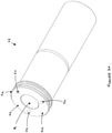
Figure 2 is an enlarged isometric cross-sectional view showing the guide pin of the disc brake according to the present invention; -
Figures 3a and3b are different views showing the sleeve portion of the embodiment of the rotational fixing; -
Figure 4 is a front view of the brake carrier showing the recess of the embodiment of the rotational fixing; -
Figures 5a ,5b and5c are different views showing how ball bearing connectors may be fitted into cavities on the sleeve portion in the embodiment of the rotational fixing; -
Figure 6 is an exploded perspective view of the disk brake according to the present invention with the embodiment of the rotational fixing; -
Figure 7 is a cross-sectional view showing the guide pin mounted on the brake carrier with the embodiment of the rotational fixing. - Referring to
Figures 1 to 7 a disc brake according to the present invention is indicated generally at 1. The disc brake comprises abrake carrier 10. The brake carrier carries an inboard brake pad 12a and an outboard brake pad 12b. A rotor 14 (shown in part) is positioned between the brake pads and is rotatable about an axisR. A caliper 16 is slidably mounted with respect to thebrake carrier 10 by at least one guide assembly. In the embodiment depicted, the disc brake comprises two guide assemblies 18a, 18b. - Each guide assembly comprises a
guide pin 20 along which thecaliper 16 can slide and abore 22 disposed in the caliper for receiving the guide pin. In the embodiment depicted, one of the guide pins 20a is shorter than the other guide pin 20b in order to accommodate vehicle installation constraints. - The
guide pin 20 comprises afastener 24 to attach the guide pin to thebrake carrier 10. The fastener is received by acomplimentary bore 26 disposed in the brake carrier. In the embodiment shown inFigures 1 to 7 , thefastener 24 for attaching the guide pin to the inboard side of the brake carrier is a threaded bolt and thebore 26 for receiving the fastener in the brake carrier is a threaded bore. When attached to the brake carrier, the guide pin extends in an axial direction A. Direction A is parallel to the axis R of rotation of the rotor and parallel to the transverse axis of the disc brake. - The
guide pin 20 further comprises aguide sleeve 28 at least substantially surrounding thefastener 24 and over which thecaliper 16 slides. The guide sleeve is a hollow, thin walled tube. The outer surface of the sleeve may be coated with PTFE or any other suitable material to aid the sliding action of the caliper along the guide pin. The guide sleeve comprises amain body 30, afirst end 32, asecond end 34 and abore hole 36 extending from the first end to the second end to receive the fastener. Each guide assembly comprises a sealingboot 38 to shroud the joint between thebrake carrier 10 and theguide sleeve 28. - The
bore 22 disposed in the caliper to receive the guide pin is an elongate hole extending from a first side (inboard) to the second side (outboard) of thecaliper 16. - During use, the
guide pin 20 will be subject to dynamic loads. To counter rotational torque, the disc brake of the present invention comprises a rotational fixing to rotationally engage theguide sleeve 28 and thebrake carrier 10 and thereby substantially restrict undesirable rotation of the guide sleeve about its longitudinal axis. - By restricting the rotation of the guide sleeve relative to the brake carrier, the transmission of rotation from the guide sleeve to the fastener is substantially avoided. Thus, the subsequent risk of loosening the fastener from the brake carrier is advantageously averted.
- To counter translational torque, the rotational fixing is also configured to translationally engage the
guide sleeve 28 and thebrake carrier 10 and thereby substantially restrict translation movement of the guide sleeve relative to the brake carrier. By translationally engaging the guide sleeve and the brake carrier, the rotational fixing helpfully substantially impedes undesirable lateral translational movement of the guide sleeve in the circumferential direction X and perpendicular translational movement of the guide sleeve in the tangential direction Y. Circumferential direction X is perpendicular to the axial direction A, perpendicular to the tangential direction Y and parallel to the longitudinal axis of the disc brake. Tangential direction Y is tangential to a circle describe by the rotation of therotor 14, perpendicular to the axial direction A, perpendicular to the longitudinal axis of the disc brake and parallel to the direction in which the brake pads 12a, 12b are inserted or removed from thebrake carrier 10. - The disc brake may comprise one or more rotational fixings to engage the guide sleeve of each guide pin and brake carrier. In the embodiment depicted in
Figures 1 to 7 , the disc brake comprises three rotational fixings to restrict the movement of each guide pin. The rotational fixings are the same type. - The rotational fixing for the disc brake comprises a sleeve portion of the guide sleeve, a receiving portion of the brake carrier for receiving the sleeve portion and an inter-connection to engage the sleeve portion and receiving portion when the sleeve portion is received in the receiving portion.
- The sleeve portion may comprise an end portion of the guide sleeve, a circumferential flange or rim of the guide sleeve. In the embodiment shown in
Figures 1 to 7 , the sleeve portion of the guide sleeve is acircumferential flange 40 arranged at thefirst end 32 of the guide sleeve. In this particular embodiment, theflange 40 has a substantially circular cross-sectional profile defined by a circularouter edge 42 and a substantiallyflat flange face 44. - The guide sleeve is mounted on the brake carrier when the sleeve portion is received by the receiving portion. The receiving portion of the brake carrier may comprise a receiving face against which the sleeve portion is located when the sleeve portion is received by the receiving portion. In the embodiment shown in
Figures 1 to 7 , the receiving portion comprises arecess 46 formed on the inboard side of the brake carrier into which theflange 40 of the guide sleeve can be fitted. Therecess 46 has a circularinner edge 48 and a substantially flat,rear recess face 50. The circularinner edge 48 defines the cross-sectional profile of the receiving portion. Therecess face 50 defines the receiving surface against which theflange face 44 abuts when it is received in the recess. Therecess face 50 is deformable. The configuration of therecess 46 compliments the configuration of theflange 40 of the guide sleeve so to help further limit translational movement of the flange when the guide pin is subjected to dynamic loads. Thebore 26 for receiving the fastener is located in therecess 46. Thebore 26 may be centrally located or eccentrically located in the recess. In the embodiment shown inFigures 1 to 7 , the opening of thebore 26 is centrally arranged in therecess face 50. The recess may be manufactured with the desired cross-sectional profile using any conventional cutting, milling or machining techniques. The bore may be manufactured by any conventional drilling techniques. - The inter-connection may comprise any suitable means to inter-lock the sleeve portion and receiving portion, when the sleeve portion is received in the receiving portion, so as to inhibit movement of the guide sleeve relative to the brake carrier.
- The inter-connection may comprise a connector co-locatable in a first cavity of the sleeve portion and a second cavity in the receiving potion when the sleeve portion is received in the receiving portion. The connector may have a cylinder, cuboid, sphere, ovoid, ellipsoid or any other suitably shaped body.
- In the embodiment shown in
Figures 1 to 7 , each inter-connection comprises aball bearing connector 52, a firstsemi-circular cavity 54 formed in theflange face 44 of the flange to receive a first sector of the ball bearing and a secondsemi-circular cavity 56 formed in therecess face 50 to receive a second sector of the ball bearing. Theball bearing connector 52, firstsemi-circular cavity 54 and secondsemi-circular cavity 56 are configured to form interference fit/press fit connections. Thefirst cavity 54 is pre-formed prior to assembling the rotational fixing. To enhance the interference fit/press fit connection and minimise tolerance effects, therecess face 50 is deformable and thesecond cavity 56 is formed during assembly of rotational fixing to receive the second sector of the ball bearing connector. When theball bearing connector 52 is co-located in the first and second cavities, the flange and recess are inter-connected and any rotation of the guide sleeve or lateral movement between the guide sleeve and brake carrier is thereby restricted. - To mount the guide pin on the brake carrier and engage the guide sleeve and the brake carrier, the
ball bearing connectors 52 are initially fitted in the firstsemi-circular cavities 54 of the flange such that they protrude from theflange face 44 of the flange. Theflange 40 with the protrudingball bearing connectors 52 is then located in therecess 46 such that theflange face 44 with the protrudingball bearing connectors 52 abuts therecess face 50. Thefastener 24 is then extended through thebore hole 26 of the guide sleeve and it is screwed into thebore 26 of the brake carrier. Under the screwing action, theball bearing connectors 52 are pushed against therecess face 50. Therecess face 50 deforms to create second cavities which receive the second sector of the ball bearing connectors. Theball bearings connectors 52 are now co-located in both the first cavities and second cavities and theco-located ball bearings 52 form a rotational and translational engagement between the flange and the recess. Sealing boots 38 are fitted to theguide sleeves 28. - When attached to the
brake carrier 10, theguide pin 20 extends in an axial direction A from the brake carrier. Due to the configuration of the inter-connection and orientation of the cavities, the co-located ball bearings extend in the axial direction A between the guide sleeve and the brake carrier. - The
caliper 16 will be mounted on the guide pin by locating the guide pin in the caliper bore 22 and sliding the caliper along the guide sleeve. - When fully assembled, the disc brake depicted in
Figure 1 can be actuated. An air actuator (not shown) is provided to move the inboard brake pad 12a into frictional contact with therotor 14. When the inboard brake pad 12a is pushed towards and contacts the rotor, the caliper slides inboard along the guide pin. As the caliper slides inboard, it moves the outboard brake pad 12b towards the rotor. Hence, the rotor becomes clamped between the inboard and outboard brake pads and the rotation of the rotor is frictionally inhibited. - It is apparent that the rotational fixing not only restricts undesirable rotation but also helps to properly align the guide sleeve relative to the brake carrier during assembly. If the flange and recess are not properly aligned, the guide sleeve will not extend in the correct direction from the brake carrier and the ball bearings may not form an engagement. As a result, an operator will not be able to mount the caliper on the guide pin. Therefore, the rotational fixing usefully protects the disk brake from operator assembly error.
- In an alternative embodiment, the receiving face of the receiving portion is a surface region of the inboard surface of the brake carrier. The receiving face surface region is substantially flush with the inboard surface. Hence, when the sleeve portion is received by the receiving portion, the guide sleeve is mounted directly on the in board surface of the brake carrier. The second cavities for the ball bearings are formed directly in the inboard surface of the brake carrier.
- Rather than forming the second cavities by pushing the ball bearings into the receiving face of the receiving portion, the second cavities may be pre-formed to form an interference or press-fit connection with the balls bearings, when the sleeve portion is received in the receiving portion and the first cavities and second cavities are aligned. The receiving face may be deformable as the ball bearings are co-located in the pre-formed second cavities to enhance the engaging connection.
- To co-locate ball bearings in a different alignment, the first cavities and second cavities may be formed in side wall portions of the flange and recess such that when the ball bearings are co-located in the cavities, the ball bearings extend in a radial direction between the sleeve portion of the guide sleeve and receiving portion of the brake carrier. The radial direction is perpendicular to the axial direction A.
- As an alternative to ball bearing connectors, the inter-connection may comprises a pin connector, a first cavity disposed in the sleeve portion to receive a first end of the pin connector and a second cavity disposed in the receiving portion to receive a second end of the pin connector.
- The inter-connection may additionally or alternatively comprise a protrusion integrally formed and extending from the sleeve portion or receiving portion and an indent formed in the corresponding portion to receive the protrusion. For example, the inter-connection may comprise one or more blades or teeth extending in an axial direction A from the sleeve portion into corresponding indents in the brake carrier.
- The rotational fixing may further comprise a friction enhancer to enhance the frictional engagement between the sleeve portion and receiving portion and thereby further limit the rotation and/or translation of the guide sleeve with respect to the brake carrier. The friction enhancer may comprise a knurled surface formed on the sleeve portion to enhance the frictional grip of the sleeve portion with the receiving portion. The knurled surface may be arranged on an outer surface or outer edge of the sleeve portion.
- Although the invention has been described above with reference to one or more preferred embodiments, it will be appreciated that various changes or modifications may be made without departing from the scope of the invention as defined in the appended claims.
Claims (13)
- A disc brake (1) comprising:a brake carrier (10);a caliper (16);at least one guide pin (20) comprising a guide sleeve (28); anda receiving portion of the brake carrier (10) to receive the guide sleeve; characterised byan inter-connection to engage the guide sleeve and the receiving portion so as to restrict rotation of the guide sleeve (28) relative to the brake carrier (10), when the guide sleeve is received by the receiving portion, wherein the guide pin (20) further comprises a guide fastener (24) to secure the guide pin (20) to the brake carrier (10), and the disc brake (1) further comprises a bore (26) formed in the brake carrier (10) to receive the guide fastener (24), wherein the bore (26) is arranged eccentrically in the receiving portion of the brake carrier (10).
- The disc brake (1) of claim 1, wherein the guide fastener (24) is configured to extend through the sleeve and the bore (26) is arranged in the receiving portion of the brake carrier (10).
- The disc brake (1) of claim 1 or claim 2, wherein the guide fastener (24) is a guide bolt.
- The disc brake (1) of claim 3, wherein the guide bolt is a threaded bolt and the bore (26) disposed in the brake carrier (10) has a complimentary threaded bore (26).
- The disc brake (1) of any of claims 2 to 4, wherein the guide fastener (24) is the inter-connection that engages the guide sleeve and the receiving portion.
- The disc brake (1) of claim 5, wherein the inter-connection comprises:a protrusion extending from the guide sleeve or the receiving portion; andan indent formed in the corresponding portion and in which the protrusion can be located when the guide sleeve is received by the receiving portion and the protrusion and indent are aligned.
- The disc brake (1) according to claim 6, wherein the inter-connection is configured to engage the guide sleeve and receiving portion so as to restrict translation of the guide sleeve (28) relative to the brake carrier (10), when the guide sleeve is received by the receiving portion.
- The disc brake (1) according to claim 6 or claim 7, wherein the guide sleeve comprises a first end portion of the guide sleeve (28), or a rim at the first end (32) of the guide sleeve (28), or a flange (40) arranged at a first end (32) of the guide sleeve (28).
- The disc brake (1) according to any of claims 6 to 8, wherein the receiving portion comprises a receiving face, optionally wherein the receiving face is a surface region of an inboard surface of the brake carrier (10) and the receiving face is substantially flush with the inboard surface.
- The disc brake (1) according to any of claims 6 to 9, wherein the receiving portion comprises a recess formed in the brake carrier (10) in which the guide sleeve is received when the guide sleeve is received by the receiving portion so as to restrict translation of the guide sleeve (28) relative to the brake carrier (10), and the receiving face being disposed in the recess.
- The disc brake (1) according to any of claims 6 to 10, wherein the protrusion comprises a blade or tooth extending outwardly from the guide sleeve or receiving portion.
- The disc brake (1) according to any of claims 6 to 11, wherein the indent is a pre-formed indent formed in the corresponding portion prior to the guide sleeve being received by the recessing portion and the protrusion being received in the indent.
- The disc brake (1) according to any of claims 6 to 12, wherein the receiving portion is deformable, the protrusion is a protrusion extending from the guide sleeve, and the indent is a formable indent in the receiving portion formed when the guide sleeve is received by the receiving portion and the protrusion is pushed against the deformable receiving portion.
Applications Claiming Priority (3)
| Application Number | Priority Date | Filing Date | Title |
|---|---|---|---|
| EP15170690.0A EP3101301B2 (en) | 2015-06-04 | 2015-06-04 | Guide assembly |
| EP16173201.1A EP3133312B1 (en) | 2015-06-04 | 2016-06-06 | Rotational fixing for a guide pin of a disc brake and method thereof |
| EP18196631.8A EP3441636B1 (en) | 2015-06-04 | 2016-06-06 | Rotational fixing for a guide pin of a disc brake and method thereof |
Related Parent Applications (2)
| Application Number | Title | Priority Date | Filing Date |
|---|---|---|---|
| EP16173201.1A Division EP3133312B1 (en) | 2015-06-04 | 2016-06-06 | Rotational fixing for a guide pin of a disc brake and method thereof |
| EP18196631.8A Division EP3441636B1 (en) | 2015-06-04 | 2016-06-06 | Rotational fixing for a guide pin of a disc brake and method thereof |
Publications (2)
| Publication Number | Publication Date |
|---|---|
| EP3617542A1 EP3617542A1 (en) | 2020-03-04 |
| EP3617542B1 true EP3617542B1 (en) | 2022-02-09 |
Family
ID=53284118
Family Applications (5)
| Application Number | Title | Priority Date | Filing Date |
|---|---|---|---|
| EP18184472.1A Active EP3415781B1 (en) | 2015-06-04 | 2015-06-04 | Guide assembly |
| EP15170690.0A Active EP3101301B2 (en) | 2015-06-04 | 2015-06-04 | Guide assembly |
| EP16173201.1A Active EP3133312B1 (en) | 2015-06-04 | 2016-06-06 | Rotational fixing for a guide pin of a disc brake and method thereof |
| EP19204415.4A Active EP3617542B1 (en) | 2015-06-04 | 2016-06-06 | Rotational fixing for a guide pin of a disc brake |
| EP18196631.8A Active EP3441636B1 (en) | 2015-06-04 | 2016-06-06 | Rotational fixing for a guide pin of a disc brake and method thereof |
Family Applications Before (3)
| Application Number | Title | Priority Date | Filing Date |
|---|---|---|---|
| EP18184472.1A Active EP3415781B1 (en) | 2015-06-04 | 2015-06-04 | Guide assembly |
| EP15170690.0A Active EP3101301B2 (en) | 2015-06-04 | 2015-06-04 | Guide assembly |
| EP16173201.1A Active EP3133312B1 (en) | 2015-06-04 | 2016-06-06 | Rotational fixing for a guide pin of a disc brake and method thereof |
Family Applications After (1)
| Application Number | Title | Priority Date | Filing Date |
|---|---|---|---|
| EP18196631.8A Active EP3441636B1 (en) | 2015-06-04 | 2016-06-06 | Rotational fixing for a guide pin of a disc brake and method thereof |
Country Status (2)
| Country | Link |
|---|---|
| US (4) | US10221904B2 (en) |
| EP (5) | EP3415781B1 (en) |
Families Citing this family (10)
| Publication number | Priority date | Publication date | Assignee | Title |
|---|---|---|---|---|
| EP3415781B1 (en) * | 2015-06-04 | 2020-04-22 | Meritor Heavy Vehicle Braking Systems (UK) Limited | Guide assembly |
| EP3371476B1 (en) * | 2015-11-05 | 2021-12-29 | KNORR-BREMSE Systeme für Nutzfahrzeuge GmbH | Disk brake for a utility vehicle |
| EP3492768B1 (en) * | 2017-11-29 | 2021-02-24 | Meritor Heavy Vehicle Braking Systems (UK) Limited | Caliper guide assembly |
| US11698115B2 (en) * | 2019-02-12 | 2023-07-11 | ZF Active Safety US Inc. | Sliding mechanism for guide pins of a disc brake assembly |
| EP3779224B1 (en) * | 2019-08-16 | 2022-10-05 | Meritor Heavy Vehicle Braking Systems (UK) Limited | A mounting for a guide pin of a disc brake |
| EP3779225B1 (en) * | 2019-08-16 | 2022-11-16 | Meritor Heavy Vehicle Braking Systems (UK) Limited | A guide assembly for a disc brake |
| EP3779226B1 (en) * | 2019-08-16 | 2022-07-06 | Meritor Heavy Vehicle Braking Systems (UK) Limited | A guide assembly for a disc brake |
| EP3872360A1 (en) * | 2020-02-28 | 2021-09-01 | Meritor Heavy Vehicle Braking Systems (UK) Limited | Caliper guide assembly |
| CN111322325B (en) * | 2020-04-07 | 2021-05-07 | 马鞍山博越精密机械有限公司 | Caliper support with adjustable installation angle and production process |
| US11773928B2 (en) | 2020-12-14 | 2023-10-03 | Arvinmeritor Technology, Llc | Brake assembly having a guide pin assembly |
Citations (2)
| Publication number | Priority date | Publication date | Assignee | Title |
|---|---|---|---|---|
| EP0035946B1 (en) * | 1980-03-10 | 1984-08-01 | The Bendix Corporation | Floating caliper disc brake |
| US20140116817A1 (en) * | 2012-11-01 | 2014-05-01 | Kelsey-Hayes Company | Guide Pin For Disc Brake Assembly And Disc Brake Assembly Including Such A Guide Pin |
Family Cites Families (36)
| Publication number | Priority date | Publication date | Assignee | Title |
|---|---|---|---|---|
| US2477969A (en) * | 1946-05-04 | 1949-08-02 | Mid Continent Metal Products C | Coupling |
| US2527871A (en) * | 1946-06-21 | 1950-10-31 | Harding F Bakewell | Toolholder |
| US3213658A (en) * | 1963-11-21 | 1965-10-26 | Buckbee Mears Co | Forming dome-shaped mesh |
| FR2142248A5 (en) | 1971-06-18 | 1973-01-26 | Dba | |
| GB2027826B (en) | 1978-06-29 | 1982-07-28 | Lucas Industries Ltd | Disc brake assembly |
| US4244451A (en) * | 1979-03-26 | 1981-01-13 | The Bendix Corporation | Disc brake and pin assembly therefor |
| FR2469615A1 (en) * | 1979-11-08 | 1981-05-22 | Dba | SLIDING CALIPER DISC BRAKE |
| US4393963A (en) * | 1980-09-26 | 1983-07-19 | The Bendix Corporation | Disc brake caliper support |
| US4596316A (en) * | 1984-02-10 | 1986-06-24 | Goodyear Aerospace Corporation | Electrically actuated aircraft brakes |
| EP0173495A3 (en) | 1984-08-18 | 1987-05-13 | LUCAS INDUSTRIES public limited company | Improvements in self-energising disc brakes |
| US4762206A (en) * | 1985-11-15 | 1988-08-09 | Nippon Air Brake Co., Ltd. | Disc brake |
| DE3614211A1 (en) | 1986-04-26 | 1987-10-29 | Goldbeckbau Gmbh | Releasable connection between steel girder and prefabricated reinforced-concrete element |
| DE8633923U1 (en) * | 1986-12-18 | 1988-04-21 | Lucas Industries P.L.C., Birmingham, West Midlands, Gb | |
| JPH048927A (en) * | 1990-04-26 | 1992-01-13 | Nissan Motor Co Ltd | Floating type disc brake |
| DE9115195U1 (en) * | 1991-12-06 | 1992-02-06 | Lucas Industries P.L.C., Birmingham, West Midlands, Gb | |
| AU4661093A (en) * | 1992-07-08 | 1994-01-31 | Joseph Rozgonyi | Cellular telephone access control and identification system |
| JPH06510358A (en) * | 1992-07-10 | 1994-11-17 | ベンディクス エスパーナ ソシエダッド アノニマ | Device that guides the sliding caliper for disc brakes |
| US5351583A (en) * | 1993-03-03 | 1994-10-04 | Patcore, Incorporated | Toothless ratchet, clutch, and mechanisms to eliminate backlash |
| DE9305631U1 (en) * | 1993-04-15 | 1994-08-25 | Lucas Ind Plc | Floating caliper brake, in particular floating caliper partial lining disc brake |
| FR2705748B1 (en) * | 1993-05-25 | 1995-07-07 | Alliedsignal Europ Services | Disc brake with sliding caliper. |
| KR100349530B1 (en) | 2000-09-07 | 2002-08-21 | 주식회사 만도 | Guide rode for disk brake |
| BR0212557B1 (en) * | 2001-09-18 | 2011-07-26 | disc brake, especially for a utility vehicle. | |
| DE10150214B4 (en) | 2001-10-12 | 2020-10-29 | Knorr-Bremse Systeme für Nutzfahrzeuge GmbH | Disc brake, in particular for a utility vehicle |
| DE10311896A1 (en) * | 2003-03-18 | 2004-09-30 | Knorr-Bremse Systeme für Nutzfahrzeuge GmbH | Disc brake, in particular for commercial vehicles |
| DE10327623B4 (en) | 2003-06-19 | 2006-07-13 | Mtu Aero Engines Gmbh | Milling process for the production of components |
| FR2905155B1 (en) * | 2006-08-23 | 2009-03-27 | Bosch Gmbh Robert | DISC BRAKE COMPRISING A AXIS HAVING A RANGE HAVING A NON-CIRCULAR PROFILE SECTION |
| US20080135352A1 (en) | 2006-12-12 | 2008-06-12 | Bendix Spicer Foundation Brake Llc | Brake caliper vertical mounting assembly joint arrangement |
| US8051958B1 (en) * | 2007-02-16 | 2011-11-08 | Kelsey-Hayes Company | Guide pin for disc brake assembly and disc brake assembly including such a guide pin |
| DE102007053902A1 (en) * | 2007-11-09 | 2009-05-20 | Knorr-Bremse Systeme für Nutzfahrzeuge GmbH | Disc brake for a commercial vehicle |
| EP2058717B1 (en) | 2007-11-12 | 2011-07-20 | Siemens Aktiengesellschaft | Method and device for operating a machine tool |
| DE102008021233A1 (en) | 2008-04-28 | 2009-10-29 | Rud Ketten Rieger & Dietz Gmbh U. Co. Kg | Conveyor chain, has chain link with inner and outer straps connected together via hinge joint, and rubber elastic element flexibly twisted and producing resetting moment acting between straps during linear extension of chain |
| US9309936B2 (en) * | 2008-11-13 | 2016-04-12 | Chassis Brakes International B.V. | Sleeve for disk brake caliper and disk brake fitted with such a sleeve |
| DE102010020588A1 (en) | 2010-05-14 | 2011-11-17 | Wabco Radbremsen Gmbh | Disc brake, in particular for commercial vehicles, and sealing of such a disc brake |
| DE102012014886A1 (en) | 2012-07-26 | 2014-01-30 | Knorr-Bremse Systeme für Nutzfahrzeuge GmbH | Clamping device of a disc brake for a commercial vehicle |
| KR102205623B1 (en) * | 2012-11-01 | 2021-01-20 | 켈시-헤이즈 컴파니 | Guide pin for disc brake assembly, disc brake assembly including such a guide pin and method for producing a disc brake assembly including such a guide pin |
| EP3415781B1 (en) * | 2015-06-04 | 2020-04-22 | Meritor Heavy Vehicle Braking Systems (UK) Limited | Guide assembly |
-
2015
- 2015-06-04 EP EP18184472.1A patent/EP3415781B1/en active Active
- 2015-06-04 EP EP15170690.0A patent/EP3101301B2/en active Active
-
2016
- 2016-06-06 EP EP16173201.1A patent/EP3133312B1/en active Active
- 2016-06-06 EP EP19204415.4A patent/EP3617542B1/en active Active
- 2016-06-06 US US15/174,080 patent/US10221904B2/en active Active
- 2016-06-06 EP EP18196631.8A patent/EP3441636B1/en active Active
- 2016-06-06 US US15/174,102 patent/US20160356326A1/en not_active Abandoned
-
2019
- 2019-03-01 US US16/290,237 patent/US20190195299A1/en not_active Abandoned
-
2020
- 2020-08-21 US US16/999,610 patent/US20200378457A1/en not_active Abandoned
Patent Citations (2)
| Publication number | Priority date | Publication date | Assignee | Title |
|---|---|---|---|---|
| EP0035946B1 (en) * | 1980-03-10 | 1984-08-01 | The Bendix Corporation | Floating caliper disc brake |
| US20140116817A1 (en) * | 2012-11-01 | 2014-05-01 | Kelsey-Hayes Company | Guide Pin For Disc Brake Assembly And Disc Brake Assembly Including Such A Guide Pin |
Also Published As
| Publication number | Publication date |
|---|---|
| EP3441636A1 (en) | 2019-02-13 |
| EP3101301B2 (en) | 2024-03-06 |
| EP3441636B1 (en) | 2019-10-23 |
| US20160356326A1 (en) | 2016-12-08 |
| US20200378457A1 (en) | 2020-12-03 |
| US10221904B2 (en) | 2019-03-05 |
| US20160356325A1 (en) | 2016-12-08 |
| EP3415781A1 (en) | 2018-12-19 |
| EP3101301B1 (en) | 2018-09-19 |
| EP3415781B1 (en) | 2020-04-22 |
| EP3101301A1 (en) | 2016-12-07 |
| EP3617542A1 (en) | 2020-03-04 |
| EP3133312B1 (en) | 2018-11-07 |
| US20190195299A1 (en) | 2019-06-27 |
| EP3133312A2 (en) | 2017-02-22 |
| EP3133312A3 (en) | 2017-03-22 |
Similar Documents
| Publication | Publication Date | Title |
|---|---|---|
| EP3617542B1 (en) | Rotational fixing for a guide pin of a disc brake | |
| US9180841B2 (en) | Disk brake | |
| EP3552839B1 (en) | Assembling structure for tire wheel, brake rotor, and hub | |
| US10781872B2 (en) | Floating collar and one-piece guide pin and bolt assembly | |
| US11560929B2 (en) | Guide assembly for a disc brake | |
| US9994205B2 (en) | Axis of a land vehicle, land vehicle with such a suspension and disk brake and brake support of such land vehicle | |
| CN111480020A (en) | Brake disc-hub connection | |
| US11603895B2 (en) | Mounting for a guide pin of a disc brake | |
| CA3073578A1 (en) | Disc brake rotor assembly | |
| US10605317B2 (en) | Fixing for a brake carrier and a mount for a disc brake and method thereof | |
| JP4532299B2 (en) | Disc brake | |
| GB2551855B (en) | Sliding caliper disc brake | |
| EP3772599A1 (en) | Brake caliper for a vehicle brake and method for assembling a brake caliper | |
| JP4432266B2 (en) | Disc brake | |
| JP2005257055A (en) | Disk brake | |
| JPH1026155A (en) | Structure for supporting outer pad of disk brake |
Legal Events
| Date | Code | Title | Description |
|---|---|---|---|
| PUAI | Public reference made under article 153(3) epc to a published international application that has entered the european phase |
Free format text: ORIGINAL CODE: 0009012 |
|
| STAA | Information on the status of an ep patent application or granted ep patent |
Free format text: STATUS: THE APPLICATION HAS BEEN PUBLISHED |
|
| AC | Divisional application: reference to earlier application |
Ref document number: 3133312 Country of ref document: EP Kind code of ref document: P Ref document number: 3441636 Country of ref document: EP Kind code of ref document: P |
|
| AK | Designated contracting states |
Kind code of ref document: A1 Designated state(s): AL AT BE BG CH CY CZ DE DK EE ES FI FR GB GR HR HU IE IS IT LI LT LU LV MC MK MT NL NO PL PT RO RS SE SI SK SM TR |
|
| STAA | Information on the status of an ep patent application or granted ep patent |
Free format text: STATUS: REQUEST FOR EXAMINATION WAS MADE |
|
| 17P | Request for examination filed |
Effective date: 20200831 |
|
| GRAP | Despatch of communication of intention to grant a patent |
Free format text: ORIGINAL CODE: EPIDOSNIGR1 |
|
| RBV | Designated contracting states (corrected) |
Designated state(s): AL AT BE BG CH CY CZ DE DK EE ES FI FR GB GR HR HU IE IS IT LI LT LU LV MC MK MT NL NO PL PT RO RS SE SI SK SM TR |
|
| STAA | Information on the status of an ep patent application or granted ep patent |
Free format text: STATUS: GRANT OF PATENT IS INTENDED |
|
| INTG | Intention to grant announced |
Effective date: 20201008 |
|
| GRAJ | Information related to disapproval of communication of intention to grant by the applicant or resumption of examination proceedings by the epo deleted |
Free format text: ORIGINAL CODE: EPIDOSDIGR1 |
|
| STAA | Information on the status of an ep patent application or granted ep patent |
Free format text: STATUS: REQUEST FOR EXAMINATION WAS MADE |
|
| INTC | Intention to grant announced (deleted) | ||
| GRAP | Despatch of communication of intention to grant a patent |
Free format text: ORIGINAL CODE: EPIDOSNIGR1 |
|
| GRAJ | Information related to disapproval of communication of intention to grant by the applicant or resumption of examination proceedings by the epo deleted |
Free format text: ORIGINAL CODE: EPIDOSDIGR1 |
|
| GRAJ | Information related to disapproval of communication of intention to grant by the applicant or resumption of examination proceedings by the epo deleted |
Free format text: ORIGINAL CODE: EPIDOSDIGR1 |
|
| GRAP | Despatch of communication of intention to grant a patent |
Free format text: ORIGINAL CODE: EPIDOSNIGR1 |
|
| GRAP | Despatch of communication of intention to grant a patent |
Free format text: ORIGINAL CODE: EPIDOSNIGR1 |
|
| STAA | Information on the status of an ep patent application or granted ep patent |
Free format text: STATUS: GRANT OF PATENT IS INTENDED |
|
| INTG | Intention to grant announced |
Effective date: 20210503 |
|
| INTC | Intention to grant announced (deleted) | ||
| INTG | Intention to grant announced |
Effective date: 20210511 |
|
| INTC | Intention to grant announced (deleted) | ||
| INTG | Intention to grant announced |
Effective date: 20210526 |
|
| GRAJ | Information related to disapproval of communication of intention to grant by the applicant or resumption of examination proceedings by the epo deleted |
Free format text: ORIGINAL CODE: EPIDOSDIGR1 |
|
| STAA | Information on the status of an ep patent application or granted ep patent |
Free format text: STATUS: REQUEST FOR EXAMINATION WAS MADE |
|
| GRAP | Despatch of communication of intention to grant a patent |
Free format text: ORIGINAL CODE: EPIDOSNIGR1 |
|
| STAA | Information on the status of an ep patent application or granted ep patent |
Free format text: STATUS: GRANT OF PATENT IS INTENDED |
|
| INTC | Intention to grant announced (deleted) | ||
| INTG | Intention to grant announced |
Effective date: 20210928 |
|
| GRAS | Grant fee paid |
Free format text: ORIGINAL CODE: EPIDOSNIGR3 |
|
| GRAA | (expected) grant |
Free format text: ORIGINAL CODE: 0009210 |
|
| STAA | Information on the status of an ep patent application or granted ep patent |
Free format text: STATUS: THE PATENT HAS BEEN GRANTED |
|
| AC | Divisional application: reference to earlier application |
Ref document number: 3133312 Country of ref document: EP Kind code of ref document: P Ref document number: 3441636 Country of ref document: EP Kind code of ref document: P |
|
| AK | Designated contracting states |
Kind code of ref document: B1 Designated state(s): AL AT BE BG CH CY CZ DE DK EE ES FI FR GB GR HR HU IE IS IT LI LT LU LV MC MK MT NL NO PL PT RO RS SE SI SK SM TR |
|
| REG | Reference to a national code |
Ref country code: GB Ref legal event code: FG4D |
|
| REG | Reference to a national code |
Ref country code: CH Ref legal event code: EP Ref country code: AT Ref legal event code: REF Ref document number: 1467692 Country of ref document: AT Kind code of ref document: T Effective date: 20220215 |
|
| REG | Reference to a national code |
Ref country code: DE Ref legal event code: R096 Ref document number: 602016069095 Country of ref document: DE |
|
| REG | Reference to a national code |
Ref country code: IE Ref legal event code: FG4D |
|
| REG | Reference to a national code |
Ref country code: LT Ref legal event code: MG9D |
|
| REG | Reference to a national code |
Ref country code: NL Ref legal event code: MP Effective date: 20220209 |
|
| REG | Reference to a national code |
Ref country code: AT Ref legal event code: MK05 Ref document number: 1467692 Country of ref document: AT Kind code of ref document: T Effective date: 20220209 |
|
| PG25 | Lapsed in a contracting state [announced via postgrant information from national office to epo] |
Ref country code: SE Free format text: LAPSE BECAUSE OF FAILURE TO SUBMIT A TRANSLATION OF THE DESCRIPTION OR TO PAY THE FEE WITHIN THE PRESCRIBED TIME-LIMIT Effective date: 20220209 Ref country code: RS Free format text: LAPSE BECAUSE OF FAILURE TO SUBMIT A TRANSLATION OF THE DESCRIPTION OR TO PAY THE FEE WITHIN THE PRESCRIBED TIME-LIMIT Effective date: 20220209 Ref country code: PT Free format text: LAPSE BECAUSE OF FAILURE TO SUBMIT A TRANSLATION OF THE DESCRIPTION OR TO PAY THE FEE WITHIN THE PRESCRIBED TIME-LIMIT Effective date: 20220609 Ref country code: NO Free format text: LAPSE BECAUSE OF FAILURE TO SUBMIT A TRANSLATION OF THE DESCRIPTION OR TO PAY THE FEE WITHIN THE PRESCRIBED TIME-LIMIT Effective date: 20220509 Ref country code: NL Free format text: LAPSE BECAUSE OF FAILURE TO SUBMIT A TRANSLATION OF THE DESCRIPTION OR TO PAY THE FEE WITHIN THE PRESCRIBED TIME-LIMIT Effective date: 20220209 Ref country code: LT Free format text: LAPSE BECAUSE OF FAILURE TO SUBMIT A TRANSLATION OF THE DESCRIPTION OR TO PAY THE FEE WITHIN THE PRESCRIBED TIME-LIMIT Effective date: 20220209 Ref country code: HR Free format text: LAPSE BECAUSE OF FAILURE TO SUBMIT A TRANSLATION OF THE DESCRIPTION OR TO PAY THE FEE WITHIN THE PRESCRIBED TIME-LIMIT Effective date: 20220209 Ref country code: ES Free format text: LAPSE BECAUSE OF FAILURE TO SUBMIT A TRANSLATION OF THE DESCRIPTION OR TO PAY THE FEE WITHIN THE PRESCRIBED TIME-LIMIT Effective date: 20220209 Ref country code: BG Free format text: LAPSE BECAUSE OF FAILURE TO SUBMIT A TRANSLATION OF THE DESCRIPTION OR TO PAY THE FEE WITHIN THE PRESCRIBED TIME-LIMIT Effective date: 20220509 |
|
| PG25 | Lapsed in a contracting state [announced via postgrant information from national office to epo] |
Ref country code: PL Free format text: LAPSE BECAUSE OF FAILURE TO SUBMIT A TRANSLATION OF THE DESCRIPTION OR TO PAY THE FEE WITHIN THE PRESCRIBED TIME-LIMIT Effective date: 20220209 Ref country code: LV Free format text: LAPSE BECAUSE OF FAILURE TO SUBMIT A TRANSLATION OF THE DESCRIPTION OR TO PAY THE FEE WITHIN THE PRESCRIBED TIME-LIMIT Effective date: 20220209 Ref country code: GR Free format text: LAPSE BECAUSE OF FAILURE TO SUBMIT A TRANSLATION OF THE DESCRIPTION OR TO PAY THE FEE WITHIN THE PRESCRIBED TIME-LIMIT Effective date: 20220510 Ref country code: FI Free format text: LAPSE BECAUSE OF FAILURE TO SUBMIT A TRANSLATION OF THE DESCRIPTION OR TO PAY THE FEE WITHIN THE PRESCRIBED TIME-LIMIT Effective date: 20220209 Ref country code: AT Free format text: LAPSE BECAUSE OF FAILURE TO SUBMIT A TRANSLATION OF THE DESCRIPTION OR TO PAY THE FEE WITHIN THE PRESCRIBED TIME-LIMIT Effective date: 20220209 |
|
| PG25 | Lapsed in a contracting state [announced via postgrant information from national office to epo] |
Ref country code: IS Free format text: LAPSE BECAUSE OF FAILURE TO SUBMIT A TRANSLATION OF THE DESCRIPTION OR TO PAY THE FEE WITHIN THE PRESCRIBED TIME-LIMIT Effective date: 20220609 |
|
| PG25 | Lapsed in a contracting state [announced via postgrant information from national office to epo] |
Ref country code: SM Free format text: LAPSE BECAUSE OF FAILURE TO SUBMIT A TRANSLATION OF THE DESCRIPTION OR TO PAY THE FEE WITHIN THE PRESCRIBED TIME-LIMIT Effective date: 20220209 Ref country code: SK Free format text: LAPSE BECAUSE OF FAILURE TO SUBMIT A TRANSLATION OF THE DESCRIPTION OR TO PAY THE FEE WITHIN THE PRESCRIBED TIME-LIMIT Effective date: 20220209 Ref country code: RO Free format text: LAPSE BECAUSE OF FAILURE TO SUBMIT A TRANSLATION OF THE DESCRIPTION OR TO PAY THE FEE WITHIN THE PRESCRIBED TIME-LIMIT Effective date: 20220209 Ref country code: EE Free format text: LAPSE BECAUSE OF FAILURE TO SUBMIT A TRANSLATION OF THE DESCRIPTION OR TO PAY THE FEE WITHIN THE PRESCRIBED TIME-LIMIT Effective date: 20220209 Ref country code: DK Free format text: LAPSE BECAUSE OF FAILURE TO SUBMIT A TRANSLATION OF THE DESCRIPTION OR TO PAY THE FEE WITHIN THE PRESCRIBED TIME-LIMIT Effective date: 20220209 Ref country code: CZ Free format text: LAPSE BECAUSE OF FAILURE TO SUBMIT A TRANSLATION OF THE DESCRIPTION OR TO PAY THE FEE WITHIN THE PRESCRIBED TIME-LIMIT Effective date: 20220209 |
|
| REG | Reference to a national code |
Ref country code: DE Ref legal event code: R097 Ref document number: 602016069095 Country of ref document: DE |
|
| PG25 | Lapsed in a contracting state [announced via postgrant information from national office to epo] |
Ref country code: AL Free format text: LAPSE BECAUSE OF FAILURE TO SUBMIT A TRANSLATION OF THE DESCRIPTION OR TO PAY THE FEE WITHIN THE PRESCRIBED TIME-LIMIT Effective date: 20220209 |
|
| PLBE | No opposition filed within time limit |
Free format text: ORIGINAL CODE: 0009261 |
|
| STAA | Information on the status of an ep patent application or granted ep patent |
Free format text: STATUS: NO OPPOSITION FILED WITHIN TIME LIMIT |
|
| 26N | No opposition filed |
Effective date: 20221110 |
|
| PG25 | Lapsed in a contracting state [announced via postgrant information from national office to epo] |
Ref country code: MC Free format text: LAPSE BECAUSE OF FAILURE TO SUBMIT A TRANSLATION OF THE DESCRIPTION OR TO PAY THE FEE WITHIN THE PRESCRIBED TIME-LIMIT Effective date: 20220209 |
|
| REG | Reference to a national code |
Ref country code: CH Ref legal event code: PL |
|
| REG | Reference to a national code |
Ref country code: BE Ref legal event code: MM Effective date: 20220630 |
|
| PG25 | Lapsed in a contracting state [announced via postgrant information from national office to epo] |
Ref country code: SI Free format text: LAPSE BECAUSE OF FAILURE TO SUBMIT A TRANSLATION OF THE DESCRIPTION OR TO PAY THE FEE WITHIN THE PRESCRIBED TIME-LIMIT Effective date: 20220209 |
|
| GBPC | Gb: european patent ceased through non-payment of renewal fee |
Effective date: 20220606 |
|
| PG25 | Lapsed in a contracting state [announced via postgrant information from national office to epo] |
Ref country code: LU Free format text: LAPSE BECAUSE OF NON-PAYMENT OF DUE FEES Effective date: 20220606 Ref country code: LI Free format text: LAPSE BECAUSE OF NON-PAYMENT OF DUE FEES Effective date: 20220630 Ref country code: IE Free format text: LAPSE BECAUSE OF NON-PAYMENT OF DUE FEES Effective date: 20220606 Ref country code: FR Free format text: LAPSE BECAUSE OF NON-PAYMENT OF DUE FEES Effective date: 20220630 Ref country code: CH Free format text: LAPSE BECAUSE OF NON-PAYMENT OF DUE FEES Effective date: 20220630 |
|
| PG25 | Lapsed in a contracting state [announced via postgrant information from national office to epo] |
Ref country code: GB Free format text: LAPSE BECAUSE OF NON-PAYMENT OF DUE FEES Effective date: 20220606 Ref country code: BE Free format text: LAPSE BECAUSE OF NON-PAYMENT OF DUE FEES Effective date: 20220630 |
|
| P01 | Opt-out of the competence of the unified patent court (upc) registered |
Effective date: 20230531 |
|
| PG25 | Lapsed in a contracting state [announced via postgrant information from national office to epo] |
Ref country code: IT Free format text: LAPSE BECAUSE OF FAILURE TO SUBMIT A TRANSLATION OF THE DESCRIPTION OR TO PAY THE FEE WITHIN THE PRESCRIBED TIME-LIMIT Effective date: 20220209 |
|
| PGFP | Annual fee paid to national office [announced via postgrant information from national office to epo] |
Ref country code: DE Payment date: 20230626 Year of fee payment: 8 |