JP4532299B2 - Disc brake - Google Patents
Disc brake Download PDFInfo
- Publication number
- JP4532299B2 JP4532299B2 JP2005021737A JP2005021737A JP4532299B2 JP 4532299 B2 JP4532299 B2 JP 4532299B2 JP 2005021737 A JP2005021737 A JP 2005021737A JP 2005021737 A JP2005021737 A JP 2005021737A JP 4532299 B2 JP4532299 B2 JP 4532299B2
- Authority
- JP
- Japan
- Prior art keywords
- caliper
- disk
- sliding body
- mounting member
- pad
- Prior art date
- Legal status (The legal status is an assumption and is not a legal conclusion. Google has not performed a legal analysis and makes no representation as to the accuracy of the status listed.)
- Expired - Fee Related
Links
Images


Description
本発明は、例えば自動車等の車両に制動力を付与するのに好適に用いられるディスクブレーキに関する。 The present invention relates to a disc brake suitably used for applying a braking force to a vehicle such as an automobile.
一般に、自動車等の車両に搭載されるディスクブレーキは、ブレーキペダルの踏込み操作によりマスタシリンダからブレーキ液圧が供給されると、一対の摩擦パッドをディスクの両面に押圧し、これによって車両に制動力を付与するものである。 In general, when a brake fluid pressure is supplied from a master cylinder by depressing a brake pedal, a disc brake mounted on a vehicle such as an automobile presses a pair of friction pads on both sides of the disc, thereby applying a braking force to the vehicle. Is given.
そして、この種の従来技術によるディスクブレーキは、車両の非回転部分に取付けられディスクの周方向に離間して該ディスクを軸方向に跨ぐ一対の腕部を有した取付部材と、該取付部材の各腕部に第1,第2のスライドピン等を用いて摺動可能に取付けられインナ側の摩擦パッドとアウタ側の摩擦パッドをディスクの両面に押圧するキャリパとを備えている(例えば、特許文献1,2参照)。 A disc brake according to this type of prior art is attached to a non-rotating portion of a vehicle and has a pair of arm portions spaced apart in the circumferential direction of the disc and straddling the disc in the axial direction. Each arm portion is slidably mounted using first and second slide pins or the like, and includes an inner friction pad and a caliper that presses the outer friction pad against both sides of the disk (for example, a patent) References 1 and 2).
また、前記取付部材とキャリパとの間には、前記取付部材の各腕部から離れた位置に第3または第4のスライドピンを設け、例えば合計3〜4本のスライドピンを用いて前記キャリパを取付部材に対しディスクの軸方向で摺動可能に支持する構成としている。 In addition, a third or fourth slide pin is provided between the mounting member and the caliper at a position away from each arm portion of the mounting member, and the caliper is used by using, for example, a total of 3 to 4 slide pins. Is configured to be slidable with respect to the mounting member in the axial direction of the disk.
ところで、上述した従来技術によるディスクブレーキは、車両の非制動時、制動時にわたってキャリパの姿勢を安定させるために、例えば合計3〜4本のスライドピンを用いて前記キャリパを取付部材に対し摺動可能に取付ける構成としているものである。 By the way, the above-described conventional disc brake slides the caliper with respect to the mounting member by using, for example, a total of 3 to 4 slide pins in order to stabilize the posture of the caliper during non-braking and braking of the vehicle. It is designed to be mounted as possible.
しかし、この場合のディスクブレーキは、例えば第3のスライドピンの取付方向が第1,第2のスライドピンに対して逆向きとなるので、摩擦パッドの交換作業等を行うときには、キャリパ全体を車両側から取外す必要が生じ、メンテナンス時の作業性が非常に悪いという問題がある。 However, the disc brake in this case has the third slide pin attached in the opposite direction with respect to the first and second slide pins, for example. There is a problem that the workability at the time of maintenance is very bad.
また、合計3〜4本のスライドピンを用いる構成であるため、これによって部品点数が増加し、組立時の作業性が悪くなる上に、全体の重量が増加する原因になり、製造コストも嵩むという問題がある。 Moreover, since it is a structure which uses a total of 3-4 slide pins, this increases a number of parts, worsens the workability | operativity at the time of an assembly, causes the whole weight to increase, and increases manufacturing cost. There is a problem.
本発明は上述した従来技術の問題に鑑みなされたもので、本発明の目的は、車両の非制動時、制動時にわたってキャリパの姿勢を安定した状態に保つことができると共に、部品点数の増加や重量の増加を抑えることができ、組立時の作業性も高めることができるようにしたディスクブレーキを提供することにある。 The present invention has been made in view of the above-described problems of the prior art, and an object of the present invention is to maintain a stable caliper posture during braking and non-braking of the vehicle, and to increase the number of parts. An object of the present invention is to provide a disc brake capable of suppressing an increase in weight and improving workability during assembly.
また、本発明の他の目的は、摩擦パッドの交換作業等を効率的に行うことができ、組立時やメンテナンス時の作業性を向上できるようにしたディスクブレーキを提供することにある。 Another object of the present invention is to provide a disc brake capable of efficiently performing friction pad replacement work and the like and improving workability during assembly and maintenance.
上述した課題を解決するため、本発明は、車両の非回転部分に取付けられディスクの周方向に離間して該ディスクを軸方向に跨ぐ一対の腕部を有した取付部材と、該取付部材の各腕部に前記ディスクの軸方向で摺動可能に設けられインナ側,アウタ側の摩擦パッドをディスクの両面に押圧するキャリパとを備え、前記取付部材の各腕部には、前記インナ側,アウタ側の摩擦パッドを前記ディスクの軸方向に摺動可能にガイドするインナ側,アウタ側のパッドガイド部を設けてなるディスクブレーキに適用される。 In order to solve the above-described problems, the present invention provides a mounting member having a pair of arms that are attached to a non-rotating portion of a vehicle and that are spaced apart in the circumferential direction of the disc and straddle the disc in the axial direction. Each arm is provided with a caliper that is slidable in the axial direction of the disk and presses the friction pad on the inner side and the outer side against both sides of the disk, and each arm part of the mounting member has the inner side, The present invention is applied to a disc brake having an inner side and an outer side pad guide portion for guiding an outer side friction pad so as to be slidable in the axial direction of the disc.
そして、請求項1の発明が採用する構成の特徴は、前記キャリパには、前記ディスクの回転方向の少なくとも一方側で前記アウタ側のパッドガイド部と対応した位置に摺動体を設け、該摺動体は、前記キャリパを前記アウタ側のパッドガイド部に対して摺動可能に支持し、前記キャリパに着脱可能に設けた別体の部材により構成したことにある。 A feature of the configuration adopted by the invention of claim 1 is that the caliper is provided with a sliding body at a position corresponding to the pad guide portion on the outer side on at least one side in the rotation direction of the disk. Is that the caliper is slidably supported with respect to the pad guide portion on the outer side, and is configured by a separate member provided detachably on the caliper .
また、請求項2の発明によると、前記取付部材の各腕部は、前記キャリパを一対のスライドピンを介して摺動可能に支持する構成とし、前記摺動体は、前記一対のスライドピンのうち外径が小さい方のスライドピンが支持される腕部側に位置して前記キャリパに設ける構成としている。 According to a second aspect of the present invention, each arm portion of the mounting member is configured to support the caliper so as to be slidable via a pair of slide pins, and the slide body includes the pair of slide pins. The caliper is provided on the side of the arm portion where the slide pin with the smaller outer diameter is supported.
また、請求項3の発明によると、前記摺動体は、前記ディスクの回転方向両側に位置して前記キャリパに設ける構成としている。 According to a third aspect of the present invention, the sliding body is provided on the caliper so as to be positioned on both sides of the disk in the rotational direction.
上述の如く、請求項1に記載の発明によれば、キャリパに設けた摺動体を、取付部材のアウタ側に位置するパッドガイド部で摺動可能に支持し、前記キャリパに着脱可能に設けた別体の部材により構成しているので、車両の非回転部分に取付けられる取付部材は、一対の腕部に摺動可能に設けたキャリパを、前記摺動体を介して例えば3点で支持することができ、車両の非制動時と制動時とにわたってキャリパの姿勢を安定した状態に保つことができる。 As described above, according to the first aspect of the present invention, the sliding body provided on the caliper is slidably supported by the pad guide portion located on the outer side of the mounting member, and is detachably provided on the caliper. Since it is constituted by a separate member, the mounting member attached to the non-rotating part of the vehicle supports a caliper provided slidably on a pair of arms, for example, at three points via the sliding body. Thus, the caliper can be maintained in a stable state during non-braking and braking of the vehicle.
このため、従来技術のように、合計3〜4本のスライドピンを用いてキャリパを取付部材に対し摺動可能に取付ける必要がなくなり、部品点数の増加を抑えることができると共に、重量の増加も防ぐことができ、組立時の作業性を高めることができる。 For this reason, it is not necessary to slidably mount the caliper to the mounting member using a total of 3 to 4 slide pins as in the prior art, and the increase in the number of parts can be suppressed and the weight is also increased. This can prevent the workability during assembly.
さらに、前記摺動体をキャリパに着脱可能に設けたキャリパとは別体の部材により構成しているので、摩擦パッドの交換作業等を行うときには、前記摺動体をキャリパから取外すことにより、摩擦パッドの交換作業を容易に行うことができ、保守、点検等を行うメンテナンス時の作業性を向上することができる。 Furthermore, before Since the caliper provided detachably Kisuri body to the caliper are constituted by separate members, when performing replacement or the like of the friction pads, by removing the sliding body from the caliper, friction The replacement work of the pad can be easily performed, and the workability at the time of maintenance for performing maintenance and inspection can be improved.
また、請求項2に記載の発明によると、摺動体は、一対のスライドピンのうち外径が小さい方のスライドピンを支持する腕部側に位置してキャリパに設ける構成としているので、例えば腕部に設けたピン挿嵌穴と外径が小さい方のスライドピンとの間にガタが発生し易い傾向になっても、前記摺動体をアウタ側のパッドガイド部に摺動可能に支持させることにより前記ガタの発生を抑え、取付部材に対するキャリパの姿勢を安定した状態に保つことができる。
Further, according to the invention of
また、請求項3に記載の発明によると、摺動体は、ディスクの回転方向両側に位置してキャリパに設ける構成としているので、ディスクの回転方向両側に位置する一対の腕部(アウタ側のパッドガイド部)により、キャリパの各摺動体を支持することができ、取付部材に対するキャリパの姿勢をより一層安定した状態に保つことができる。
According to the invention described in
以下、本発明の実施の形態によるディスクブレーキを、添付図面の図1〜図16に従って詳細に説明する。 Hereinafter, a disc brake according to an embodiment of the present invention will be described in detail with reference to FIGS.
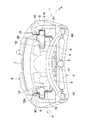
ここで、図1ないし図7は本発明の第1の実施の形態を示している。図中、1は車輪と共に回転するディスク、2は該ディスク1のインナ側となる位置で車両の非回転部分に一体的に取付けられる取付部材を示している。 Here, FIG. 1 to FIG. 7 show a first embodiment of the present invention. In the figure, reference numeral 1 denotes a disk that rotates together with the wheel, and 2 denotes an attachment member that is integrally attached to a non-rotating portion of the vehicle at a position on the inner side of the disk 1.
そして、この取付部材2は、ディスク1の周方向に離間して該ディスク1の外周を跨ぐようにディスク1の軸方向に延びる一対の腕部3,3と、該腕部3,3の基端側(インナ側)を図3、図4に示すように連結した板状の連結部4と、各腕部3の先端側(アウタ側)間を弓状に細長く延びて該各腕部3の先端側を互いに連結した補強ビーム5とにより構成され、これらは鋳造等の手段を用いて一体に成形されている。
The
また、取付部材2の各腕部3には、図1に示す如く後述するスライドピン12,13用のピン挿嵌穴3A,3Aが有底のガイド穴として軸方向に形成されている。そして、これらの腕部3の基端側にはインナ側のパッドガイド部3Bが、先端側にはアウタ側のパッドガイド部3Cが、図3、図4に示すようにそれぞれ略コ字形状をなして形成されている。また、各パッドガイド部3B,3Cの下側には、図4に示す如く内側に向けて突出した各トルク受部3D(アウタ側のみ図示)が設けられている。
Further, as shown in FIG. 1,
そして、取付部材2の各腕部3は、インナ側のパッドガイド部3Bとアウタ側のパッドガイド部3Cとに後述する各摩擦パッド15の耳部15Aがパッドスプリング16を介して摺動可能に係合され、これらの摩擦パッド15をディスク1の軸方向に摺動可能にガイドすると共に、各摩擦パッド15を介したディスク1からの回転トルクを各トルク受部3Dで受承するものである。
Each
この場合、アウタ側のパッドガイド部3Cは、図3に示す如くインナ側のパッドガイド部3B(寸法L1 )よりも大なる寸法L2 (L2 >L1 )に形成され、このために腕部3の長さL(ディスク1の軸方向長さ)は、従来品よりも長く形成されている。
In this case, the outer side
即ち、アウタ側のパッドガイド部3Cは、後述の摺動体17をアウタ側の摩擦パッド15と共に摺動可能に支持するため、摺動体17の摺動範囲分だけディスク1の軸方向に長く形成されているものである。
That is, the outer side
また、取付部材2の連結部4には、図2、図4に示すように各腕部3の下側に位置して一対のねじ穴4A,4Bが形成され、これらのねじ穴4A,4Bには、取付部材2を車両のナックル部(非回転部分)に取付けるための締結部材(いずれも図示せず)が螺着されるものである。
Further, as shown in FIGS. 2 and 4, a pair of
なお、ディスク1が図2中の矢示A方向に回転する場合を想定すると、前記ねじ穴4A,4Bのうち一方のねじ穴4Aは、ディスク1の回転方向入口側に配置され、他方のねじ穴4Bは、ディスク1の回転方向出口側に配置されるものである。
Assuming that the disk 1 rotates in the direction of arrow A in FIG. 2, one
6は取付部材2に摺動可能に支持されるキャリパで、該キャリパ6は、図1、図2に示す如くディスク1の外周側を跨いで軸方向に延びるブリッジ部7と、該ブリッジ部7の一側に一体形成され、ディスク1のインナ側に配設されるインナ脚部としてのシリンダ部8と、ブリッジ部7の他側に一体形成され、ディスク1のアウタ側に配設されるアウタ脚部としての爪部9,9等とにより構成されている。
A
そして、キャリパ6には、シリンダ部8の左,右両側からディスク1の周方向に突出する一対の取付部10,10が一体に設けられ、これらの取付部10,10には、図1に示すように後述のスライドピン12,13が取付けられるものである。また、キャリパ6のシリンダ部8には、図2に示すピストン11が摺動可能に挿嵌されるシリンダボア8A(図6参照)が形成されている。
The
また、キャリパ6のアウタ脚部となる爪部9,9は、図2、図6に示すように二又状をなして形成されている。そして、これらの爪部9,9のうち、例えばディスク1の回転方向出口側に位置する爪部9には、図1、図2および図5に示すように後述の摺動体17を取付けるための取付座9Aが設けられている。
Further, the
ここで、摺動体17用の取付座9Aは、図5、図6に示すように爪部9の側面(ディスク1の回転方向出口側の側面)に開口する略U字状の凹溝として形成されている。そして、この爪部9には、取付座9Aの底面側に位置してねじ穴9Bが穿設され、該ねじ穴9Bには、後述のボルト18が螺着されるものである。
Here, the
12,13はキャリパ6の取付部10,10に設けられたスライドピンで、該スライドピン12,13は、図1に示す如く基端側がピンボルト14,14を介して取付部10,10に取付けられ、先端側が各腕部3のピン挿嵌穴3A内に摺動可能に挿嵌されている。これにより、キャリパ6は、スライドピン12,13を介して取付部材2によりディスク1の軸方向に摺動可能に支持されるものである。
また、スライドピン12,13のうち、ディスク1の回転方向入口側に位置するスライドピン12は、キャリパ6を支持するためのメインピンとなり、他方のスライドピン13よりも大なる外径に形成される。そして、ディスク1の回転方向出口側に位置する他方のスライドピン13はサブピンとなり、前述のスライドピン12よりも外径が小さく形成されている。
Of the slide pins 12 and 13, the
ここで、サブピンとなるスライドピン13と腕部3のピン挿嵌穴3Aとの間のクリアランス(径方向の隙間)は、メインピンとなるスライドピン12側よりも大きく形成され、この径方向の隙間によって、キャリパ6を取付部材2に取付けるときの寸法誤差等が吸収されるものである。
Here, the clearance (radial gap) between the
15,15はディスク1の両側に配置されたインナ側,アウタ側の摩擦パッドで、該各摩擦パッド15は、ブレーキ操作時にキャリパ6(ピストン11)によりディスク1の両面に押圧され、ディスク1に対して制動力を付与するものである。ここで、各摩擦パッド15には、ディスク1の回転方向両側となる位置に一対の耳部15A,15A(1個のみ図示)が突設されている。
そして、各摩擦パッド15の耳部15Aは、後述のパッドスプリング16を介して取付部材2のパッドガイド部3B,3C内に摺動可能に挿嵌され、これにより摩擦パッド15は、各耳部15Aを介して取付部材2の各腕部3に摺動可能に支持されるものである。
And the ear | edge
16,16は各腕部3のパッドガイド部3B,3Cに設けられた一対のパッドスプリングで、該各パッドスプリング16は、図1に示す如く、パッドガイド部3B,3Cと共に摩擦パッド15を耳部15A等を介してディスク1の軸方向に摺動可能に案内するものである。
また、これらのパッドスプリング16,16は、アウタ側のパッドガイド部3C(図3に示す寸法L2 )に対応して、ディスク1の軸方向寸法が従来品よりも長く形成されている。そして、ディスク1の回転方向出口側に位置するパッドスプリング16は、アウタ側のパッドガイド部3C内に配置され、このパッドガイド部3Cと共に後述の摺動体17をディスク1の軸方向に摺動可能に案内する機能も有している。
The pad springs 16 and 16 are formed such that the axial dimension of the disk 1 is longer than that of the conventional product, corresponding to the outer side
17はキャリパ6のアウタ脚部となる爪部9に設けられた摺動体で、該摺動体17は、キャリパ6とは別体の部材により構成され、キャリパ6をアウタ側のパッドガイド部3Cに対して摺動可能に支持させるものである。そして、摺動体17は、図1、図2に示すようにキャリパ6の爪部9,9のうち、例えばディスク1の回転方向出口側に位置する爪部9に締結部材としてのボルト18を介して着脱可能に取付けられる。
即ち、摺動体17の基端側は、図5ないし図7に示す如く爪部9に設けた取付座9A内にボルト18を用いて締着され、取付座9A内に廻止め状態で保持されるものである。また、摺動体17の先端側は、ディスク1の回転方向出口側に位置する腕部3(アウタ側のパッドガイド部3C)に向けて突出する突出部17Aとなっている。そして、摺動体17は、この突出部17Aがアウタ側のパッドガイド部3Cにパッドスプリング16を介して摺動可能に支持されるものである。
That is, the base end side of the sliding
ここで、摺動体17は、図7に示す如く横断面が略四角形の柱状体として形成され、その基端側にはボルト18用の挿通穴17Bが穿設されている。そして、この挿通穴17Bは、ボルト18の軸径よりも僅かに大径に形成され、これにより、取付座9Aに対する摺動体17の取付位置は、挿通穴17Bとボルト18との間のクリアランス(径方向の隙間)分だけ位置補正可能となっている。
Here, the sliding
本実施の形態によるディスクブレーキは、上述の如き構成を有するもので、次に、その作用について説明する。 The disc brake according to the present embodiment has the above-described configuration, and the operation thereof will be described next.
まず、ブレーキ操作時にキャリパ6のシリンダ部8(図6に示すシリンダボア8A)内に外部からブレーキ液圧を供給することより、該シリンダ部8内でピストン11を摺動変位させ、インナ側(シリンダ部8側)の摩擦パッド15をディスク1の一側に向けて押圧する。
First, by supplying brake fluid pressure from the outside into the cylinder portion 8 (cylinder bore 8A shown in FIG. 6) of the
そして、このときの反力でキャリパ6全体がスライドピン12,13、摺動体17を介して取付部材2に対しディスク1の軸方向に摺動変位され、これによって、アウタ脚部となる爪部9,9は、アウタ側の摩擦パッド15をディスク1の他側面に押圧する。
At this time, the
このため、ディスク1はインナ側の摩擦パッド15とアウタ側の摩擦パッド15とにより両面側から強く挟持され、例えば走行中の車両に制動力を付与するものである。また、ブレーキ操作を解除したときには、ディスク1の両面から各摩擦パッド15が離間して、前記車両に対する制動力を解除することになる。
For this reason, the disk 1 is strongly sandwiched between the inner
ところで、車両に制動力を付与するため、インナ側,アウタ側の摩擦パッド15,15をディスク1の両面に押圧したときには、ディスク1からの回転トルクが各摩擦パッド15を介して取付部材2のトルク受部3Dに付加される。
By the way, when the inner and
このとき、キャリパ6のアウタ脚部となる爪部9は、ディスク1の回転トルクによる影響をアウタ側の摩擦パッド15を介して受け易く、これによってキャリパ6全体が回転トルクの影響で変位することがあり、キャリパ6の姿勢を安定させることが難しくなる。また、前記スライドピン12,13と各腕部3のピン挿嵌穴3Aとの間にガタが発生すると、車両の非制動時においてもキャリパ6の姿勢を安定させることが難しくなる。
At this time, the
そこで、本実施の形態にあっては、キャリパ6のアウタ脚部を構成する一対の爪部9,9のうち、例えばディスク1の回転方向出口側に位置する爪部9に凹溝状の取付座9Aとねじ穴9Bとを設け、摺動体17の基端側を取付座9A内にボルト18を用いて着脱可能に取付けると共に、摺動体17の先端側(図5に示す突出部17A側)を、アウタ側のパッドガイド部3Cにパッドスプリング16を介して摺動可能に支持させる構成としている。
Therefore, in the present embodiment, of the pair of
このために、キャリパ6は、シリンダ部8(取付部10)側の左,右のスライドピン12,13と爪部9側の摺動体17とにより、取付部材2に対して3点で支持されることになり、これによって、取付部材2に対するキャリパ6の姿勢を安定した状態に保つことができる。
Therefore, the
そして、この場合には、従来技術のように3〜4本のスライドピンを用いる必要がないので、部品点数の増加や重量の増大等を防ぐことができ、組立時の作業性を確実に高めることができる。 In this case, since it is not necessary to use 3 to 4 slide pins as in the prior art, it is possible to prevent an increase in the number of parts, an increase in weight, and the like, and the workability during assembly is reliably improved. be able to.
また、爪部9に対する摺動体17の取付作業は、当該ディスクブレーキを車両に組付けるときの最終段階で行えばよい。しかも、ボルト18が挿通される摺動体17の挿通穴17Bは、ボルト18の軸径よりも僅かに大径に形成されているので、摺動体17を爪部9の取付座9Aにボルト18で締結するときには、挿通穴17Bとボルト18との間の径方向隙間(クリアランス)分だけ摺動体17の設置位置を簡単に位置調整することができる。
Moreover, what is necessary is just to perform the attachment operation | work of the sliding
このため、組付けの最終段階で摺動体17を爪部9に取付けるときには、アウタ側のパッドガイド部3C(パッドスプリング16)に対して摺動体17の突出部17A側を適正な取付位置に設定でき、これによっても取付部材2に対するキャリパ6の姿勢を安定した状態に保持することができる。
For this reason, when the sliding
従って、本実施の形態によれば、車両の非制動時と制動時にわたりキャリパ6の姿勢を安定した状態に保つことができると共に、部品点数の増加や重量の増加を抑えることができ、組立時の作業性も高めることができる。
Therefore, according to the present embodiment, the posture of the
しかも、摺動体17は、爪部9の取付座9Aにボルト18を用いて着脱可能に取付けるので、例えば摩擦パッド15の交換等を行うメンテナンス時には、爪部9から摺動体17を取外すことにより、キャリパ6全体を取付部材2から取外す必要もなく、摩擦パッド15の交換作業等を容易に行うことができ、メンテナンス時の作業性を大幅に向上することができる。
Moreover, since the sliding
また、本実施の形態にあっては、キャリパ6のアウタ脚部を構成する一対の爪部9,9のうち、例えばディスク1の回転方向出口側に位置する爪部9に摺動体17を設ける構成としている。即ち、図1に示す左,右のスライドピン12,13のうち、キャリパ6を支持するためのメインピンとなるスライドピン12側ではなく、他方のサブピンとなるスライドピン13側に摺動体17を設ける構成としている。
Further, in the present embodiment, among the pair of
これにより、キャリパ6を取付部材2に取付けるときの寸法誤差等を吸収するため、腕部3のピン挿嵌穴3Aとスライドピン13との間のクリアランス(径方向の隙間)を予め大きく形成した場合でも、このスライドピン13側のガタ等を摺動体17により吸収することが可能となる。
Thereby, in order to absorb a dimensional error or the like when the
即ち、摺動体17は、図1に示す如くスライドピン13の先端側に近い位置でアウタ側のパッドガイド部3Cにパッドスプリング16を介して摺動可能に支持されるので、腕部3のピン挿嵌穴3Aとスライドピン13との間のクリアランスを大きく取った場合でも、取付部材2に対するキャリパ6の姿勢を安定した状態に保つことができる。
That is, the sliding
次に、図8および図9は本発明の第2の実施の形態を示し、本実施の形態では、前述した第1の実施の形態と同一の構成要素に同一の符号を付し、その説明を省略するものとする。しかし、本実施の形態の特徴は、摺動体21の先端側(突出部)に円柱部21Aを設ける構成としたことにある。
Next, FIG. 8 and FIG. 9 show a second embodiment of the present invention. In this embodiment, the same reference numerals are given to the same components as those in the first embodiment described above, and the description thereof will be given. Shall be omitted. However, a feature of the present embodiment is that a
ここで、摺動体21は、第1の実施の形態で述べた摺動体17とほぼ同様に構成され、その基端側にはボルト18用の挿通穴21Bが穿設されている。しかし、この場合の摺動体21には、ディスク1の軸方向に短尺の円柱形状をなして延びる円柱部21Aが形成されている点で、第1の実施の形態とは相違しているものである。
Here, the sliding
そして、摺動体21は、図8に示すように爪部9の取付座9A内にボルト18を用いて着脱可能に取付けられ、摺動体21の円柱部21Aは、アウタ側のパッドガイド部3C内にパッドスプリング16を介して摺動可能に配置される。このときに、摺動体21の円柱部21Aは、パッドガイド部3C内でパッドスプリング16に対して線接触に近い状態で摺動変位(接触)するものである。
As shown in FIG. 8, the sliding
かくして、このように構成される本実施の形態でも、キャリパ6は、左,右のスライドピン12,13と爪部9側の摺動体21とにより、取付部材2に対して3点で支持されることになり、これによって、取付部材2に対するキャリパ6の姿勢を安定した状態に保つことができ、前記第1の実施の形態とほぼ同様の作用効果を得ることができる。
Thus, also in the present embodiment configured as described above, the
特に、本実施の形態では、摺動体21の円柱部21Aが、パッドガイド部3C内でパッドスプリング16に対して線接触に近い状態で摺動変位するため、両者の接触面積を小さくして摺動抵抗を低減できると共に、アウタ側のパッドガイド部3C内で摺動体21の円柱部21Aを円滑に摺動変位させることができる。
In particular, in the present embodiment, the
次に、図10は本発明の第3の実施の形態を示し、本実施の形態では、前述した第1の実施の形態と同一の構成要素に同一の符号を付し、その説明を省略するものとする。しかし、本実施の形態の特徴は、摺動体31の先端側(突出部)に球形部31Aを設ける構成としたことにある。
Next, FIG. 10 shows a third embodiment of the present invention. In this embodiment, the same components as those in the first embodiment described above are denoted by the same reference numerals, and the description thereof is omitted. Shall. However, a feature of the present embodiment is that a
ここで、摺動体31は、第1の実施の形態で述べた摺動体17とほぼ同様に構成され、その基端側にはボルト18用の挿通穴31Bが穿設されている。しかし、この場合の摺動体31は、その先端側に球形部31Aが形成されている点で相違しているものである。
Here, the sliding
そして、摺動体31は、図10に示すように爪部9の取付座9A内にボルト18を用いて着脱可能に取付けられ、摺動体31の球形部31Aは、例えば図8に示すパッドガイド部3C内でパッドスプリング16に対して点接触に近い状態で摺動変位(接触)するものである。
The sliding
かくして、このように構成される本実施の形態でも、取付部材2に対するキャリパ6の姿勢を安定した状態に保つことができ、前記第1の実施の形態とほぼ同様の作用効果を得ることができる。特に、本実施の形態では、摺動体31の球形部31Aにより点接触に近い摺動状態を確保することができ、摺動抵抗をより効果的に低減することができる。
Thus, even in the present embodiment configured as described above, the posture of the
次に、図11および図12は本発明の第4の実施の形態を示し、本実施の形態の特徴は、キャリパのアウタ脚部に2個の摺動体を設ける構成としたことにある。なお、本実施の形態では、前述した第1の実施の形態と同一の構成要素に同一の符号を付し、その説明を省略するものとする。 Next, FIGS. 11 and 12 show a fourth embodiment of the present invention. The feature of this embodiment is that two slide bodies are provided on the outer leg portion of the caliper. In the present embodiment, the same components as those in the first embodiment described above are denoted by the same reference numerals, and the description thereof is omitted.
図中、41は本実施の形態で採用するキャリパで、該キャリパ41は、第1の実施の形態で述べたキャリパ6とほぼ同様に構成され、ブリッジ部7、インナ脚部としてのシリンダ部8、左,右の取付部10,10等を有している。しかし、この場合のキャリパ41は、後述の爪部42,42が異なる形状に形成されているものである。
In the figure,
42,42はキャリパ41のアウタ脚部を構成する一対の爪部で、該各爪部42は、第1の実施の形態で述べた爪部9と同様に二又形状をなして形成されている。しかし、この爪部42,42には、それぞれ取付座42Aとねじ穴(図示せず)が形成されている点で、第1の実施の形態とは相違している。
42 and 42 are a pair of claw portions constituting the outer leg portion of the
43,43は本実施の形態で採用した2個の摺動体で、該各摺動体43は、第1の実施の形態で述べた摺動体17と同様に形成されている。しかし、この場合の摺動体43,43は、キャリパ41の爪部42,42に取付座42A,42Aを介して取付けられる点で第1の実施の形態とは異なるものである。
即ち、各摺動体43の基端側は、各爪部42の取付座42A内にボルト18を用いて締着され、取付座42A内に廻止め状態で保持されるものである。また、摺動体43,43の先端側は、ディスク1の回転方向両側(入口側,出口側)に位置する各腕部3(アウタ側のパッドガイド部3C)に向けて突出し、アウタ側の各パッドガイド部3Cにパッドスプリング16を介して摺動可能に支持されている。
That is, the base end side of each sliding
かくして、このように構成される本実施の形態でも、前記第1の実施の形態とほぼ同様の作用効果を得ることができる。特に、本実施の形態では、シリンダ部8側のスライドピン12,13(図1参照)と爪部42,42側の摺動体43,43とにより、キャリパ41を取付部材2に対して4点で支持することができ、取付部材2に対するキャリパ6の姿勢をより一層安定した状態に保つことができる。
Thus, in the present embodiment configured as described above, it is possible to obtain substantially the same operational effects as those of the first embodiment. In particular, in the present embodiment, the
なお、前述した第1の実施の形態では、ディスク1の回転方向出口側に位置する爪部9に摺動体17を設ける場合を例に挙げて説明した。しかし、本発明はこれに限らず、例えばスライドピン12,13のうち、サブピンとなるスライドピンがディスクの回転方向入口側に設けられるタイプのディスクブレーキの場合には、ディスクの回転方向入口側となる爪部の位置に摺動体(摺動体)を取付ける構成とするのがよいものである。
In the first embodiment described above, the case where the sliding
そして、この点は前記第2,第3の実施の形態で用いた摺動体21,31についても同様である。また、前記第4の実施の形態で述べた一対の摺動体43、43のように、ディスク1の回転方向両側に前述の摺動体21,31をそれぞれ設ける構成としてもよいものである。
Then, the point is the same with the sliding
1 ディスク
2 取付部材
3 腕部
3A ピン挿嵌穴
3B インナ側のパッドガイド部
3C アウタ側のパッドガイド部
6,41 キャリパ
7 ブリッジ部
8 シリンダ部(インナ脚部)
8A シリンダボア
9,42 爪部(アウタ脚部)
10 取付部
11 ピストン
12,13 スライドピン
15 摩擦パッド
16 パッドスプリング
17,21,31,43 摺動体
18 ボルト(締結部材)
DESCRIPTION OF SYMBOLS 1
8A Cylinder bore 9, 4 2 claw (outer leg)
DESCRIPTION OF
Claims (3)
前記キャリパには、前記ディスクの回転方向の少なくとも一方側で前記アウタ側のパッドガイド部と対応した位置に摺動体を設け、該摺動体は、前記キャリパを前記アウタ側のパッドガイド部に対して摺動可能に支持し、前記キャリパに着脱可能に設けた別体の部材により構成したことを特徴とするディスクブレーキ。 A mounting member attached to a non-rotating portion of the vehicle and having a pair of arms spaced apart in the circumferential direction of the disk and straddling the disk in the axial direction, and sliding on each arm of the mounting member in the axial direction of the disk And a caliper that presses the inner and outer friction pads against both sides of the disk, and the inner and outer friction pads are placed in the axial direction of the disk on each arm of the mounting member. In disc brakes that have pad guides on the inner and outer sides that are slidably guided,
The caliper is provided with a sliding body at a position corresponding to the outer side pad guide portion on at least one side in the rotational direction of the disc, and the sliding body moves the caliper with respect to the outer side pad guide portion. A disc brake characterized in that it is constituted by a separate member that is slidably supported and detachably provided on the caliper .
Priority Applications (1)
| Application Number | Priority Date | Filing Date | Title |
|---|---|---|---|
| JP2005021737A JP4532299B2 (en) | 2005-01-28 | 2005-01-28 | Disc brake |
Applications Claiming Priority (1)
| Application Number | Priority Date | Filing Date | Title |
|---|---|---|---|
| JP2005021737A JP4532299B2 (en) | 2005-01-28 | 2005-01-28 | Disc brake |
Publications (3)
| Publication Number | Publication Date |
|---|---|
| JP2006207722A JP2006207722A (en) | 2006-08-10 |
| JP2006207722A5 JP2006207722A5 (en) | 2008-02-14 |
| JP4532299B2 true JP4532299B2 (en) | 2010-08-25 |
Family
ID=36964812
Family Applications (1)
| Application Number | Title | Priority Date | Filing Date |
|---|---|---|---|
| JP2005021737A Expired - Fee Related JP4532299B2 (en) | 2005-01-28 | 2005-01-28 | Disc brake |
Country Status (1)
| Country | Link |
|---|---|
| JP (1) | JP4532299B2 (en) |
Families Citing this family (3)
| Publication number | Priority date | Publication date | Assignee | Title |
|---|---|---|---|---|
| JP5847561B2 (en) * | 2011-11-29 | 2016-01-27 | 日立オートモティブシステムズ株式会社 | Disc brake |
| JP6165218B2 (en) * | 2015-11-24 | 2017-07-19 | 日立オートモティブシステムズ株式会社 | Disc brake |
| DE112020005788T5 (en) * | 2019-11-27 | 2022-09-22 | Hitachi Astemo, Ltd. | disc brake |
Citations (6)
| Publication number | Priority date | Publication date | Assignee | Title |
|---|---|---|---|---|
| JPS55124638U (en) * | 1979-02-26 | 1980-09-04 | ||
| JPS59151634A (en) * | 1983-02-11 | 1984-08-30 | ソシエテ・アノニム・デー・ベー・アー | Disk brake |
| JPS60191727U (en) * | 1984-05-30 | 1985-12-19 | アイシン精機株式会社 | Vehicle disc brake |
| JPH0577633U (en) * | 1992-03-23 | 1993-10-22 | 日信工業株式会社 | Split caliper body for vehicle disc brakes |
| JPH08189538A (en) * | 1995-01-11 | 1996-07-23 | Nissin Kogyo Kk | Caliper body support structure of disc brake for pin slide type vehicle |
| JPH09250572A (en) * | 1996-03-15 | 1997-09-22 | Akebono Brake Ind Co Ltd | Disc brake |
-
2005
- 2005-01-28 JP JP2005021737A patent/JP4532299B2/en not_active Expired - Fee Related
Patent Citations (6)
| Publication number | Priority date | Publication date | Assignee | Title |
|---|---|---|---|---|
| JPS55124638U (en) * | 1979-02-26 | 1980-09-04 | ||
| JPS59151634A (en) * | 1983-02-11 | 1984-08-30 | ソシエテ・アノニム・デー・ベー・アー | Disk brake |
| JPS60191727U (en) * | 1984-05-30 | 1985-12-19 | アイシン精機株式会社 | Vehicle disc brake |
| JPH0577633U (en) * | 1992-03-23 | 1993-10-22 | 日信工業株式会社 | Split caliper body for vehicle disc brakes |
| JPH08189538A (en) * | 1995-01-11 | 1996-07-23 | Nissin Kogyo Kk | Caliper body support structure of disc brake for pin slide type vehicle |
| JPH09250572A (en) * | 1996-03-15 | 1997-09-22 | Akebono Brake Ind Co Ltd | Disc brake |
Also Published As
| Publication number | Publication date |
|---|---|
| JP2006207722A (en) | 2006-08-10 |
Similar Documents
| Publication | Publication Date | Title |
|---|---|---|
| JP5847561B2 (en) | Disc brake | |
| EP2787238A1 (en) | Disc-brake device and calipers | |
| JP7075848B2 (en) | Disc brake | |
| US20180106310A1 (en) | Disc brake device | |
| JP3774068B2 (en) | Disc brake | |
| US4191278A (en) | Slidable support structure for a disc brake caliper | |
| JP2004286216A (en) | One piece sliding brake caliper | |
| JP4532299B2 (en) | Disc brake | |
| JP4881864B2 (en) | Disc brake with small carrier | |
| KR20110060243A (en) | Disk brake | |
| JP4718422B2 (en) | Disc brake | |
| US20230099439A1 (en) | Vehicle disc brake arrangement, brake pad, and vehicle | |
| JP5332014B2 (en) | Decorative plate mounting structure | |
| JP2014167323A (en) | Disc brake | |
| US20080156595A1 (en) | Disc brake apparatus of opposed-piston type | |
| JP4730955B2 (en) | Disc brake | |
| JP4928478B2 (en) | Disc brake | |
| JP2017106516A (en) | Disc brake | |
| JPH11247910A (en) | Disc brake device | |
| US20120298454A1 (en) | Brake Pad Retention System | |
| US20230108312A1 (en) | Brake pad retainer system, brake pad, and vehicle | |
| JP6052615B2 (en) | Reaction type disc brake | |
| JP4918419B2 (en) | Drum brake with shoe clearance automatic adjustment mechanism | |
| KR20090077183A (en) | Disc brake for vehicle | |
| JP3502248B2 (en) | Disc brake |
Legal Events
| Date | Code | Title | Description |
|---|---|---|---|
| A521 | Written amendment |
Free format text: JAPANESE INTERMEDIATE CODE: A523 Effective date: 20071221 |
|
| A621 | Written request for application examination |
Free format text: JAPANESE INTERMEDIATE CODE: A621 Effective date: 20071221 |
|
| A711 | Notification of change in applicant |
Free format text: JAPANESE INTERMEDIATE CODE: A712 Effective date: 20090831 |
|
| RD03 | Notification of appointment of power of attorney |
Free format text: JAPANESE INTERMEDIATE CODE: A7423 Effective date: 20090831 |
|
| A521 | Written amendment |
Free format text: JAPANESE INTERMEDIATE CODE: A523 Effective date: 20090904 |
|
| A977 | Report on retrieval |
Free format text: JAPANESE INTERMEDIATE CODE: A971007 Effective date: 20090929 |
|
| TRDD | Decision of grant or rejection written | ||
| A01 | Written decision to grant a patent or to grant a registration (utility model) |
Free format text: JAPANESE INTERMEDIATE CODE: A01 Effective date: 20100608 |
|
| A01 | Written decision to grant a patent or to grant a registration (utility model) |
Free format text: JAPANESE INTERMEDIATE CODE: A01 |
|
| A61 | First payment of annual fees (during grant procedure) |
Free format text: JAPANESE INTERMEDIATE CODE: A61 Effective date: 20100610 |
|
| R150 | Certificate of patent or registration of utility model |
Ref document number: 4532299 Country of ref document: JP Free format text: JAPANESE INTERMEDIATE CODE: R150 Free format text: JAPANESE INTERMEDIATE CODE: R150 |
|
| FPAY | Renewal fee payment (event date is renewal date of database) |
Free format text: PAYMENT UNTIL: 20130618 Year of fee payment: 3 |
|
| FPAY | Renewal fee payment (event date is renewal date of database) |
Free format text: PAYMENT UNTIL: 20130618 Year of fee payment: 3 |
|
| FPAY | Renewal fee payment (event date is renewal date of database) |
Free format text: PAYMENT UNTIL: 20140618 Year of fee payment: 4 |
|
| LAPS | Cancellation because of no payment of annual fees |