EP3613921A1 - Outil destiné à l'orientation horizontale des objets - Google Patents
Outil destiné à l'orientation horizontale des objets Download PDFInfo
- Publication number
- EP3613921A1 EP3613921A1 EP19192439.8A EP19192439A EP3613921A1 EP 3613921 A1 EP3613921 A1 EP 3613921A1 EP 19192439 A EP19192439 A EP 19192439A EP 3613921 A1 EP3613921 A1 EP 3613921A1
- Authority
- EP
- European Patent Office
- Prior art keywords
- tool
- support
- support element
- carrier plate
- devices
- Prior art date
- Legal status (The legal status is an assumption and is not a legal conclusion. Google has not performed a legal analysis and makes no representation as to the accuracy of the status listed.)
- Granted
Links
- 238000005253 cladding Methods 0.000 claims abstract description 31
- 238000000034 method Methods 0.000 claims description 5
- 238000010276 construction Methods 0.000 description 7
- 239000000853 adhesive Substances 0.000 description 6
- 230000001070 adhesive effect Effects 0.000 description 6
- 238000009434 installation Methods 0.000 description 4
- -1 polyethylene Polymers 0.000 description 4
- 230000003670 easy-to-clean Effects 0.000 description 3
- 239000012530 fluid Substances 0.000 description 3
- 238000009413 insulation Methods 0.000 description 3
- 230000007774 longterm Effects 0.000 description 3
- 229910052573 porcelain Inorganic materials 0.000 description 3
- 229910052572 stoneware Inorganic materials 0.000 description 3
- 238000009736 wetting Methods 0.000 description 3
- 239000004698 Polyethylene Substances 0.000 description 2
- 239000004743 Polypropylene Substances 0.000 description 2
- 229910000831 Steel Inorganic materials 0.000 description 2
- 229910001069 Ti alloy Inorganic materials 0.000 description 2
- 238000011109 contamination Methods 0.000 description 2
- 229910052751 metal Inorganic materials 0.000 description 2
- 239000002184 metal Substances 0.000 description 2
- 229920003023 plastic Polymers 0.000 description 2
- 239000004033 plastic Substances 0.000 description 2
- 229920000573 polyethylene Polymers 0.000 description 2
- 229920001155 polypropylene Polymers 0.000 description 2
- 239000004800 polyvinyl chloride Substances 0.000 description 2
- 229920000915 polyvinyl chloride Polymers 0.000 description 2
- 239000010959 steel Substances 0.000 description 2
- 239000004575 stone Substances 0.000 description 2
- 238000004026 adhesive bonding Methods 0.000 description 1
- 239000011449 brick Substances 0.000 description 1
- 239000004568 cement Substances 0.000 description 1
- 230000005611 electricity Effects 0.000 description 1
- 239000003292 glue Substances 0.000 description 1
- 238000003780 insertion Methods 0.000 description 1
- 230000037431 insertion Effects 0.000 description 1
- 238000004519 manufacturing process Methods 0.000 description 1
- 230000008092 positive effect Effects 0.000 description 1
- 239000007787 solid Substances 0.000 description 1
Images


Classifications
-
- E—FIXED CONSTRUCTIONS
- E04—BUILDING
- E04F—FINISHING WORK ON BUILDINGS, e.g. STAIRS, FLOORS
- E04F21/00—Implements for finishing work on buildings
- E04F21/0007—Implements for finishing work on buildings for mounting doors, windows or frames; their fitting
-
- E—FIXED CONSTRUCTIONS
- E04—BUILDING
- E04F—FINISHING WORK ON BUILDINGS, e.g. STAIRS, FLOORS
- E04F21/00—Implements for finishing work on buildings
- E04F21/18—Implements for finishing work on buildings for setting wall or ceiling slabs or plates
- E04F21/1838—Implements for finishing work on buildings for setting wall or ceiling slabs or plates for setting a plurality of similar elements
- E04F21/1844—Implements for finishing work on buildings for setting wall or ceiling slabs or plates for setting a plurality of similar elements by applying them one by one
- E04F21/185—Temporary edge support brackets
Definitions
- the invention relates to a tool for the horizontal alignment of objects according to the preamble of claim 1.
- the AT 413 229 B discloses a tool for the horizontal alignment of wall cladding elements comprising at least one block-shaped stiffening element with a full or hollow profile and strip-shaped extension elements. By plugging stiffening elements together, the tool can be extended or an angle can be formed.
- the object of the invention is therefore to provide a tool of the type mentioned at the outset with which the disadvantages mentioned can be avoided, with which objects, in particular wall cladding elements, can be aligned simply, stably and horizontally in a short time.
- the tool can be set up and leveled quickly and easily on the construction site. A build-up that does not wobble can be achieved in a short time.
- the tool is also versatile, robust and easy to clean. Since no pipe guides or the like are provided, the tool also works with a certain amount of dirt. Due to the simple design of the tool, even inexperienced or non-specialist persons can use the tool easily, safely and properly. It is also advantageous that the tool can also be used for large format laying due to the stability of the tool.
- the invention further relates to a method for the horizontal alignment of objects according to claim 14.
- the object of the invention is therefore to provide a method of the type mentioned at the outset with which the disadvantages mentioned are avoided, with which objects, in particular wall cladding elements, can be aligned in a simple, stable and horizontal manner in a short time.
- the 1 to 6 show at least parts of preferred embodiments of a tool 1 for the horizontal alignment of objects, in particular wall cladding elements and / or windows and / or furniture, comprising at least one support element 3 with a support device 5 designed for supporting the object and adjustment devices 4 for the horizontal alignment of the support device 5 in at least one first axis.
- the tool 1 can be set up and leveled quickly and easily on the construction site. In this way, a structure that does not wobble can be achieved in a short time. Tool 1 is also versatile, robust and easy to clean. Since no pipe guides or the like are provided, the tool 1 also works with a certain amount of contamination. Due to the simple design of the tool 1, even inexperienced or non-specialist persons can use the tool 1 simply, safely and properly. It is also advantageous that, due to the stability of the tool 1, the tool 1 can also be used for large format laying.
- the tool 1 is used for lifting and in particular for the horizontal alignment of objects.
- the tool 1 also serves to hold objects, in particular if the object or objects are aligned horizontally by means of the tool 1, in particular to facilitate the assembly of the object or objects.
- Typical wall cladding elements are, for example, tiles, tiles, slabs, facing bricks or stone slabs.
- the tool 1 is used to support and horizontally align windows, particularly when installing them. There is often only a small space available for installing windows.
- windows or balcony doors can be heavy. Since the tool 1 is very stable and compact due to its construction, heavy windows or balcony doors can be easily supported and aligned horizontally by means of the tool 1. Furthermore, furniture or devices can also be supported and aligned horizontally using the tool 1.
- the tool 1 preferably functions purely mechanically.
- the tool 1 therefore does not require electricity or additional hydraulic or pneumatic devices which are cumbersome and difficult to operate.
- the support element 3 can in particular be made of metal, for example from a steel or from a titanium alloy, or from a plastic, for example from Polyvinyl chloride, made of polyethylene or polypropylene, consists and serves to support at least one object.
- at least one wall cladding element can be glued to the wall using tile adhesive, the lower edge of the wall cladding element being supported on the support device 5 of the support element 3, as a result of which the wall cladding element cannot slide any further downward in the direction of the floor.
- Windows or doors or their frames can be supported and raised on the support device 5 of the support element 3 or aligned horizontally by means of the setting devices 4.
- the support device 5 is designed as a narrow extension and that a long side of the support device 5 connects to the rest of the support element 3. This means that the support device 5 protrudes only slightly beyond the rest of the tool 1.
- the long side can in particular be normal to the first axis. This means that even narrow objects such as wall cladding elements can be supported without excessive tilting moments.
- the support device 5 can have, in particular, a flat support surface on the upper side.
- the support element 3 is formed in one piece.
- the tool 1 has a single support element 3.
- the tool 1 has a spirit level.
- a horizontal alignment of the support device 5 can be reliably checked by the spirit level.
- the adjustment devices 4 are designed as screws, in particular as wing screws, which is exemplified in FIG Fig. 3 or 6 is shown. Screwing is a particularly precise and continuous Alignment of the support device 5 is possible, but the height of the support device 5 can also be adjusted well.
- the length of the tool 1 is at least 3 cm, in particular at least 7 cm, preferably at least 10 cm.
- the length of the tool is normal to the first axis.
- the length of the tool 1 is a maximum of 30 cm, in particular a maximum of 25 cm, preferably a maximum of 20 cm.
- the width of the tool 1 is at least 3 cm, in particular at least 7 cm, preferably at least 10 cm.
- the width of the tool runs parallel to the first axis.
- the width of the tool 1 is a maximum of 30 cm, in particular a maximum of 25 cm, preferably a maximum of 20 cm.
- the height of the tool 1 is at least 2 cm, in particular at least 5 cm, preferably at least 7 cm.
- the height of the tool 1 is a maximum of 15 cm, in particular a maximum of 12 cm, preferably a maximum of 7 cm.
- the tool 1 has an essentially square base area.
- the ratio of the length to the width of the support element 3 is 4 to 1 to 1 to 4.
- the support element 3 has a greater length than width.
- the support element 3 is connected to a frame 7 via the setting devices 4, the frame 7 having a mounting surface 9 for mounting on a surface.
- the frame 7 enables a compact and easy-to-use design.
- the frame 7 and / or the mounting surface 9 are made of metal, for example of a steel or a titanium alloy.
- the frame 7 and / or the mounting surface 9 can also be made from a plastic, for example from polyvinyl chloride, from polyethylene or from polypropylene.
- the frame 7 and the mounting surface 9 are formed in one piece.
- the base area denotes the resulting projected total area of the tool 1 when looking normally at the installation area 9.
- the support element 3 is attached to the frame 7 by means of the adjusting devices 4.
- the support device 5 can be arranged particularly low, as a result of which objects can be easily and reliably positioned just above the surface.
- the frame can in particular have at least two openings for the setting devices 4.
- the frame 7 forms a cavity with the installation surface 9, in which the support element 3 is arranged, whereby a particularly space-saving construction is achieved.
- the frame 7 has at least one guide device 10, the at least one guide device 10 preventing the support element 3 from tilting in a second axis that is normal to the first axis.
- the at least one guide device 10 preventing the support element 3 from tilting in a second axis that is normal to the first axis.
- the guide device 10 is slot-shaped and at least one guide element 8, which protrudes from the support element 3 and is plate-shaped, is movable in one direction in the guide device 10.
- the slot-shaped guide device 10 in cooperation with the guide element 8 allows the guide element 8 to move along the slot, thereby preventing the support element 3 from tilting in the second axis with respect to the slot.
- the guide element 8 is self-locking on the support device 5 with a predetermined load.
- the load when objects are supported does not rest solely on the setting devices 4, but is at least partially transferred to the at least one guide element 8.
- a distance between the support device 5 and the guide element 8 can be greater than the distance between the adjusting devices 4 and the guide element 8.
- the tilting moment on the guide element 8 is greater with a force on the support device 5 than with a comparable force on the adjusting devices 4 ,
- the tool 1 comprises a carrier plate 2, that the carrier plate 2 has the at least one support element 3, and that adjustment devices 4 for the horizontal alignment of the carrier plate 2 are fastened to the carrier plate 2 in at least two axes.
- a tool 1 for the horizontal alignment of objects, in particular wall cladding elements, on a substantially vertical wall comprising the support plate 2 with at least one support element 3 designed for supporting the object, in particular wall cladding element, and adjusting devices 4 for horizontal alignment attached to the support plate 2 the carrier plate 2 can be provided in at least two axes.
- Such an embodiment is exemplary in the 4 to 6 shown.
- the carrier plate 2 and the support element 3 can be aligned horizontally in at least two axes.
- the axes are normal to each other in the plane of the carrier plate 2.
- Tool 1 is also versatile, robust and easy to clean. Since no pipe guides or the like are provided, the tool 1 also works with a certain amount of contamination. Due to the simple design of the tool 1, even inexperienced or non-specialist persons can use the tool 1 simply, safely and properly. It is also advantageous that, due to the stability of the tool 1, the tool 1 can also be used for large format laying.
- the support element 3 is designed as an elongated extension and that a longitudinal extension of the support element 3 runs parallel to an edge 6 of the carrier plate 2 adjoining the support element 3. In other words, the support element 3 protrudes beyond the edge 6 of the carrier plate 2, which enables a flat support of an object on the support device 5 of the support element 3.
- the at least one support element 3 is attached to an underside of the carrier plate 2. This has a positive effect on the stability of the tool 1 and allows the support device 5 to be arranged low.
- the at least one support element 3 is detachably fastened, in particular screwed, to the support plate 2.
- the at least one support element 3 on the Carrier plate 2 is formed.
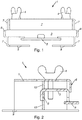
- the carrier plate 2 is essentially rectangular, which is exemplified in FIG Fig. 1 is shown.
- the adjusting devices 4 are designed as height-adjustable feet 11 of the carrier plate 2.
- the feet 11 form the footprint 9 on the underside thereof. This enables a particularly simple construction of the tool 1.
- the height-adjustable feet 11 make it easy to compensate for uneven floors or uneven floors, which is a decisive factor for the horizontal alignment of the tool 1, in particular for the horizontal alignment of the support element 3.
- At least three adjusting devices 4, preferably four adjusting devices 4, are arranged in corner regions of the carrier plate 2.
- at least three adjusting devices 4 are attached to the carrier plate 2 in a triangular arrangement.
- the carrier plate 2 can be triangular.
- the triangular arrangement of the setting devices 4 on the carrier plate 2 enables the tool 1 to be set up on an uneven surface without shaking.
- more than three adjustment devices 4 are attached to the carrier plate 2, at least 3 adjustment devices 4 being arranged in a triangular shape.
- an adjusting device 4 is not arranged in each corner area. Due to the large distance between the individual setting devices 4, the tool 1 can be set or aligned precisely.
- one or more adjustment devices 4 are arranged in the middle or in a central region of the carrier plate 2.
- the carrier plate 2 has more setting devices 4 than corners.
- five setting devices 4 can be arranged on a square carrier plate 2 or, for example, six setting devices 4 on a pentagonal carrier plate 2.
- the base area of the carrier plate 2 is at least 80%, in particular at least 85%, preferably at least 90%, of the area of the tool 1.
- the ratio of the base area of the carrier plate 2 to the support element 3 is at least four to one, in particular at least six to one, preferably at least eight to one. This ensures that the tool 1 has a short lever due to the ratio of the size of the carrier plate 2 to the support element 3, which affects the stability of the tool 1 when supporting at least one object, in particular wall covering element, on the support device 5 of the support element 3.
- the mass of the carrier plate 2 is at least 80%, in particular at least 85%, preferably at least 90%, of the total weight of the tool 1. Due to the relatively high mass of the support plate 2, the tool 1 gains decisive stability and it is possible, for example, to glue large format tiles or other heavy wall cladding elements to a wall and to position the lower edge on the support element 3, without the tool 1 being affected by this load tilts or slips.
- the thickness of the carrier plate 2 is at least three times, in particular at least five times, preferably at least ten times, the thickness of the support element 3.
- a thickness of the support element 3 is at least 1.5 mm, in particular at least 2.5 mm, preferably at least 3.0 mm.
- the thickness of the support element 3 is a maximum of 3.5 mm, in particular a maximum of 4 mm, preferably a maximum of 5 mm.
- a thickness of the carrier plate 2 is at least 1 cm, in particular at least 1.5 cm, preferably at least 2.0 cm.
- carrier plate 2 and the support element 3 are in one piece.
- the support element 3 is detachably attached to the support plate 2, in particular screwed on.
- the support plate 2 and the support element 3 can have bores, in particular threaded bores, which are arranged in alignment when the support element 3 is fastened to the support plate 2 and through which bores screws are carried out or screwed in and optionally screwed with a lock nut. Due to the releasable attachment of the support element 3 to the carrier plate 2, the support element 3 can be easily exchanged or cleaned. For heavy wall cladding elements, for example, a more solid support element 3 can be attached to the carrier plate 2.
- the support element 3 is designed as a plate which, viewed in supervision, protrudes over the base surface of the carrier plate 2 at both ends 6 of the carrier plate 2 arranged on the end face.
- the support element 3 preferably has a greater length than the carrier plate 2 and projects in particular on both edges 6 of the end faces of the carrier plate 2 beyond the surface of the carrier plate 2.
- the carrier plate 2 has bores, in particular threaded bores, in which the adjusting devices 4 are arranged.
- the setting devices 4 are designed as screws with corresponding lock nuts or merely as screws that are screwed into the threaded bores. As a result, the height of the tool 1 can be adjusted simply and precisely.
- the Guide the adjustment devices 4 past the support element 3, which is exemplified in Fig. 6 is shown. It can be provided here that the support element 3 is attached centrally to the support plate 2 and that the adjusting devices 4 are each attached next to the support element 3. In this embodiment, the support element 3 has no bores for the arrangement of the adjusting devices 4.
- the tool 1 When installing wall cladding elements, the tool 1 is preferably positioned such that an end face of the support element 3 touches a wall or an essentially flat surface to which one or more wall cladding elements are to be fastened.
- One or both edges 6 of the carrier plate 2 arranged at the end are preferably designed as a contact surface for at least one wall covering element.
- the carrier plate 2 is flat on an upper side.
- a spirit level can be placed on the top of the carrier plate 2 in order to determine a horizontal orientation of the tool 1 and corresponding to the support element 3.
- a system comprising at least two tools 1 arranged at a distance from one another is preferably provided, the support device 5 of the support elements 3 of the tools 1 being adjusted by means of their setting devices 4 such that the support device 5 are arranged in alignment in one plane, so that an object is positioned on at least one two support device 5 of the tools 1 can be aligned.
- Three or more than three tools 1 can also be used to support the object and align it horizontally. Due to the stable and compact design of the tool 1, it can also be used in areas with little space, in particular when installing windows. For example, a window with its frame, in particular with the lower edge of the frame, can be supported and aligned on the support devices 5 of the tools 1.
- the support elements 3 are set by means of the setting devices 4 such that the support devices 5 of the support elements 3 are arranged in alignment in one plane are.
- a method for the horizontal alignment of objects comprising at least one support element 3 with a support device 5 designed for supporting the object and adjustment devices 4 for horizontal alignment of the support device 5 in at least one first axis, the at least one tool 1 being positioned on a substantially flat surface, at least one object being positioned on the at least one support device 5 of the support element 3 and being aligned by means of at least one adjusting device 4.
- more than one object is positioned on at least one tool 1.
- two corners more precisely two lower edges, can be supported on the support device 5 of the support element 3 by a tool 1 by two wall cladding elements which are mounted next to one another.
- a further tool 1 can support the further corners or lower edges of the wall cladding elements and align them horizontally.
- Windows can preferably be supported with two or three tools 1 and aligned horizontally.
- Objects can advantageously also be aligned horizontally on floors with a slight inclination, since this inclination can be compensated for by aligning the support element 3 by means of at least one adjusting device 4.
Landscapes
- Engineering & Computer Science (AREA)
- Architecture (AREA)
- Civil Engineering (AREA)
- Structural Engineering (AREA)
- Finishing Walls (AREA)
Applications Claiming Priority (2)
| Application Number | Priority Date | Filing Date | Title |
|---|---|---|---|
| AT507032018 | 2018-08-20 | ||
| ATA50945/2018A AT521640B1 (de) | 2018-08-20 | 2018-11-05 | Werkzeug |
Publications (2)
| Publication Number | Publication Date |
|---|---|
| EP3613921A1 true EP3613921A1 (fr) | 2020-02-26 |
| EP3613921B1 EP3613921B1 (fr) | 2021-08-04 |
Family
ID=67659575
Family Applications (1)
| Application Number | Title | Priority Date | Filing Date |
|---|---|---|---|
| EP19192439.8A Active EP3613921B1 (fr) | 2018-08-20 | 2019-08-20 | Outil destiné à l'orientation horizontale des objets |
Country Status (1)
| Country | Link |
|---|---|
| EP (1) | EP3613921B1 (fr) |
Citations (3)
| Publication number | Priority date | Publication date | Assignee | Title |
|---|---|---|---|---|
| AT413229B (de) | 2004-03-18 | 2005-12-15 | Bernd Klampfer | Fliesenansatzschiene |
| GB2424668A (en) * | 2005-03-30 | 2006-10-04 | Damion Wilcox | Wheeled door stabiliser |
| CN207647133U (zh) * | 2017-12-20 | 2018-07-24 | 任启山 | 一种墙砖高低调节器 |
-
2019
- 2019-08-20 EP EP19192439.8A patent/EP3613921B1/fr active Active
Patent Citations (3)
| Publication number | Priority date | Publication date | Assignee | Title |
|---|---|---|---|---|
| AT413229B (de) | 2004-03-18 | 2005-12-15 | Bernd Klampfer | Fliesenansatzschiene |
| GB2424668A (en) * | 2005-03-30 | 2006-10-04 | Damion Wilcox | Wheeled door stabiliser |
| CN207647133U (zh) * | 2017-12-20 | 2018-07-24 | 任启山 | 一种墙砖高低调节器 |
Also Published As
| Publication number | Publication date |
|---|---|
| EP3613921B1 (fr) | 2021-08-04 |
Similar Documents
| Publication | Publication Date | Title |
|---|---|---|
| EP1294995A1 (fr) | Plaque de revetement de sol | |
| EP3224426B1 (fr) | Moyen d'assemblage verrouillable et procédé de son utilisation | |
| DE1196345B (de) | Verfahren zum Einbau von Stuetzen fuer auf-gestaenderte Plattenfussboeden sowie Kopfplatten und Montagelehren zur Durchfuehrung des Verfahrens | |
| AT521640B1 (de) | Werkzeug | |
| DE3529877C1 (en) | Apparatus for bridging expansion joints | |
| DE202020107451U1 (de) | Trennvorrichtung | |
| EP3613921B1 (fr) | Outil destiné à l'orientation horizontale des objets | |
| EP3940168B1 (fr) | Sous-construction destinée à la réception des profilés visibles, ainsi que pièce rapportée et element de blocage | |
| DE102015010894B4 (de) | Montagebausatz für den Terrassenbau | |
| EP0619406B1 (fr) | Cale de serrage pour la pose de planches de parquet | |
| DE202013010369U1 (de) | Montageelement für Dielen, Fliesen oder dergleichen | |
| DE4439647A1 (de) | Fugenkreuz zum Festlegen von Fugen beim Verlegen von Fliesen oder Platten | |
| AT507059B1 (de) | Wandverbund | |
| EP3784846B1 (fr) | Espaceur pour joint entre mur et revêtement de sol | |
| DE102016111211A1 (de) | Schalungssystem für die Errichtung niedriger Bauabschnitte aus Ortbeton | |
| CH717142B1 (de) | Verbindungsvorrichtung zum Verbinden von Dielen oder Platten mit Trägern. | |
| DE102016124988B4 (de) | Beschlag und Verfahren für das Verlegen von Terrassendielen | |
| EP2189594B1 (fr) | Dispositif d'appui de parapet, agencement d'appui de parapet et protection contre la chute | |
| DE2825552A1 (de) | Vorrichtung zum verlegen von platten, steinen o.dgl. | |
| DE102018103287A1 (de) | Vorrichtung und System zum Verlegen von Platten auf einer Unterlage | |
| EP3816366B1 (fr) | Construction d'appui pourvu de plusieurs éléments profilés allongés | |
| CH662599A5 (de) | Verfahren zur herstellung einer loesbaren verbindung zweier flaechen und verbindungselement zur ausfuehrung des verfahrens. | |
| DE102006053706B4 (de) | Bodenaufbausystem für aufgestelzte Bodenbeläge sowie Verfahren zur Montage des Systems | |
| EP3922784A1 (fr) | Dispositif de nivellement et de retrait | |
| DE102010022142A1 (de) | Einstellbauteil, Einstellsystem umfassend ein derartiges Einstellbauteil sowie Verfahren zum Aufbau einer ebenen Fläche |
Legal Events
| Date | Code | Title | Description |
|---|---|---|---|
| PUAI | Public reference made under article 153(3) epc to a published international application that has entered the european phase |
Free format text: ORIGINAL CODE: 0009012 |
|
| STAA | Information on the status of an ep patent application or granted ep patent |
Free format text: STATUS: THE APPLICATION HAS BEEN PUBLISHED |
|
| AK | Designated contracting states |
Kind code of ref document: A1 Designated state(s): AL AT BE BG CH CY CZ DE DK EE ES FI FR GB GR HR HU IE IS IT LI LT LU LV MC MK MT NL NO PL PT RO RS SE SI SK SM TR |
|
| AX | Request for extension of the european patent |
Extension state: BA ME |
|
| STAA | Information on the status of an ep patent application or granted ep patent |
Free format text: STATUS: REQUEST FOR EXAMINATION WAS MADE |
|
| 17P | Request for examination filed |
Effective date: 20200826 |
|
| RBV | Designated contracting states (corrected) |
Designated state(s): AL AT BE BG CH CY CZ DE DK EE ES FI FR GB GR HR HU IE IS IT LI LT LU LV MC MK MT NL NO PL PT RO RS SE SI SK SM TR |
|
| STAA | Information on the status of an ep patent application or granted ep patent |
Free format text: STATUS: EXAMINATION IS IN PROGRESS |
|
| 17Q | First examination report despatched |
Effective date: 20201203 |
|
| GRAP | Despatch of communication of intention to grant a patent |
Free format text: ORIGINAL CODE: EPIDOSNIGR1 |
|
| STAA | Information on the status of an ep patent application or granted ep patent |
Free format text: STATUS: GRANT OF PATENT IS INTENDED |
|
| INTG | Intention to grant announced |
Effective date: 20210507 |
|
| GRAS | Grant fee paid |
Free format text: ORIGINAL CODE: EPIDOSNIGR3 |
|
| GRAA | (expected) grant |
Free format text: ORIGINAL CODE: 0009210 |
|
| STAA | Information on the status of an ep patent application or granted ep patent |
Free format text: STATUS: THE PATENT HAS BEEN GRANTED |
|
| AK | Designated contracting states |
Kind code of ref document: B1 Designated state(s): AL AT BE BG CH CY CZ DE DK EE ES FI FR GB GR HR HU IE IS IT LI LT LU LV MC MK MT NL NO PL PT RO RS SE SI SK SM TR |
|
| REG | Reference to a national code |
Ref country code: GB Ref legal event code: FG4D Free format text: NOT ENGLISH |
|
| REG | Reference to a national code |
Ref country code: AT Ref legal event code: REF Ref document number: 1417137 Country of ref document: AT Kind code of ref document: T Effective date: 20210815 |
|
| REG | Reference to a national code |
Ref country code: CH Ref legal event code: EP |
|
| REG | Reference to a national code |
Ref country code: DE Ref legal event code: R096 Ref document number: 502019001951 Country of ref document: DE |
|
| REG | Reference to a national code |
Ref country code: IE Ref legal event code: FG4D Free format text: LANGUAGE OF EP DOCUMENT: GERMAN |
|
| REG | Reference to a national code |
Ref country code: LT Ref legal event code: MG9D |
|
| REG | Reference to a national code |
Ref country code: NL Ref legal event code: MP Effective date: 20210804 |
|
| PG25 | Lapsed in a contracting state [announced via postgrant information from national office to epo] |
Ref country code: SE Free format text: LAPSE BECAUSE OF FAILURE TO SUBMIT A TRANSLATION OF THE DESCRIPTION OR TO PAY THE FEE WITHIN THE PRESCRIBED TIME-LIMIT Effective date: 20210804 Ref country code: RS Free format text: LAPSE BECAUSE OF FAILURE TO SUBMIT A TRANSLATION OF THE DESCRIPTION OR TO PAY THE FEE WITHIN THE PRESCRIBED TIME-LIMIT Effective date: 20210804 Ref country code: FI Free format text: LAPSE BECAUSE OF FAILURE TO SUBMIT A TRANSLATION OF THE DESCRIPTION OR TO PAY THE FEE WITHIN THE PRESCRIBED TIME-LIMIT Effective date: 20210804 Ref country code: ES Free format text: LAPSE BECAUSE OF FAILURE TO SUBMIT A TRANSLATION OF THE DESCRIPTION OR TO PAY THE FEE WITHIN THE PRESCRIBED TIME-LIMIT Effective date: 20210804 Ref country code: HR Free format text: LAPSE BECAUSE OF FAILURE TO SUBMIT A TRANSLATION OF THE DESCRIPTION OR TO PAY THE FEE WITHIN THE PRESCRIBED TIME-LIMIT Effective date: 20210804 Ref country code: PT Free format text: LAPSE BECAUSE OF FAILURE TO SUBMIT A TRANSLATION OF THE DESCRIPTION OR TO PAY THE FEE WITHIN THE PRESCRIBED TIME-LIMIT Effective date: 20211206 Ref country code: NO Free format text: LAPSE BECAUSE OF FAILURE TO SUBMIT A TRANSLATION OF THE DESCRIPTION OR TO PAY THE FEE WITHIN THE PRESCRIBED TIME-LIMIT Effective date: 20211104 Ref country code: LT Free format text: LAPSE BECAUSE OF FAILURE TO SUBMIT A TRANSLATION OF THE DESCRIPTION OR TO PAY THE FEE WITHIN THE PRESCRIBED TIME-LIMIT Effective date: 20210804 Ref country code: BG Free format text: LAPSE BECAUSE OF FAILURE TO SUBMIT A TRANSLATION OF THE DESCRIPTION OR TO PAY THE FEE WITHIN THE PRESCRIBED TIME-LIMIT Effective date: 20211104 |
|
| PG25 | Lapsed in a contracting state [announced via postgrant information from national office to epo] |
Ref country code: PL Free format text: LAPSE BECAUSE OF FAILURE TO SUBMIT A TRANSLATION OF THE DESCRIPTION OR TO PAY THE FEE WITHIN THE PRESCRIBED TIME-LIMIT Effective date: 20210804 Ref country code: LV Free format text: LAPSE BECAUSE OF FAILURE TO SUBMIT A TRANSLATION OF THE DESCRIPTION OR TO PAY THE FEE WITHIN THE PRESCRIBED TIME-LIMIT Effective date: 20210804 Ref country code: GR Free format text: LAPSE BECAUSE OF FAILURE TO SUBMIT A TRANSLATION OF THE DESCRIPTION OR TO PAY THE FEE WITHIN THE PRESCRIBED TIME-LIMIT Effective date: 20211105 |
|
| PG25 | Lapsed in a contracting state [announced via postgrant information from national office to epo] |
Ref country code: NL Free format text: LAPSE BECAUSE OF FAILURE TO SUBMIT A TRANSLATION OF THE DESCRIPTION OR TO PAY THE FEE WITHIN THE PRESCRIBED TIME-LIMIT Effective date: 20210804 |
|
| REG | Reference to a national code |
Ref country code: BE Ref legal event code: MM Effective date: 20210831 |
|
| PG25 | Lapsed in a contracting state [announced via postgrant information from national office to epo] |
Ref country code: DK Free format text: LAPSE BECAUSE OF FAILURE TO SUBMIT A TRANSLATION OF THE DESCRIPTION OR TO PAY THE FEE WITHIN THE PRESCRIBED TIME-LIMIT Effective date: 20210804 |
|
| REG | Reference to a national code |
Ref country code: DE Ref legal event code: R097 Ref document number: 502019001951 Country of ref document: DE |
|
| PG25 | Lapsed in a contracting state [announced via postgrant information from national office to epo] |
Ref country code: SM Free format text: LAPSE BECAUSE OF FAILURE TO SUBMIT A TRANSLATION OF THE DESCRIPTION OR TO PAY THE FEE WITHIN THE PRESCRIBED TIME-LIMIT Effective date: 20210804 Ref country code: SK Free format text: LAPSE BECAUSE OF FAILURE TO SUBMIT A TRANSLATION OF THE DESCRIPTION OR TO PAY THE FEE WITHIN THE PRESCRIBED TIME-LIMIT Effective date: 20210804 Ref country code: RO Free format text: LAPSE BECAUSE OF FAILURE TO SUBMIT A TRANSLATION OF THE DESCRIPTION OR TO PAY THE FEE WITHIN THE PRESCRIBED TIME-LIMIT Effective date: 20210804 Ref country code: MC Free format text: LAPSE BECAUSE OF FAILURE TO SUBMIT A TRANSLATION OF THE DESCRIPTION OR TO PAY THE FEE WITHIN THE PRESCRIBED TIME-LIMIT Effective date: 20210804 Ref country code: LU Free format text: LAPSE BECAUSE OF NON-PAYMENT OF DUE FEES Effective date: 20210820 Ref country code: EE Free format text: LAPSE BECAUSE OF FAILURE TO SUBMIT A TRANSLATION OF THE DESCRIPTION OR TO PAY THE FEE WITHIN THE PRESCRIBED TIME-LIMIT Effective date: 20210804 Ref country code: CZ Free format text: LAPSE BECAUSE OF FAILURE TO SUBMIT A TRANSLATION OF THE DESCRIPTION OR TO PAY THE FEE WITHIN THE PRESCRIBED TIME-LIMIT Effective date: 20210804 Ref country code: AL Free format text: LAPSE BECAUSE OF FAILURE TO SUBMIT A TRANSLATION OF THE DESCRIPTION OR TO PAY THE FEE WITHIN THE PRESCRIBED TIME-LIMIT Effective date: 20210804 |
|
| PLBE | No opposition filed within time limit |
Free format text: ORIGINAL CODE: 0009261 |
|
| STAA | Information on the status of an ep patent application or granted ep patent |
Free format text: STATUS: NO OPPOSITION FILED WITHIN TIME LIMIT |
|
| 26N | No opposition filed |
Effective date: 20220506 |
|
| PG25 | Lapsed in a contracting state [announced via postgrant information from national office to epo] |
Ref country code: IT Free format text: LAPSE BECAUSE OF FAILURE TO SUBMIT A TRANSLATION OF THE DESCRIPTION OR TO PAY THE FEE WITHIN THE PRESCRIBED TIME-LIMIT Effective date: 20210804 Ref country code: IE Free format text: LAPSE BECAUSE OF NON-PAYMENT OF DUE FEES Effective date: 20210820 Ref country code: BE Free format text: LAPSE BECAUSE OF NON-PAYMENT OF DUE FEES Effective date: 20210831 |
|
| PG25 | Lapsed in a contracting state [announced via postgrant information from national office to epo] |
Ref country code: SI Free format text: LAPSE BECAUSE OF FAILURE TO SUBMIT A TRANSLATION OF THE DESCRIPTION OR TO PAY THE FEE WITHIN THE PRESCRIBED TIME-LIMIT Effective date: 20210804 |
|
| PG25 | Lapsed in a contracting state [announced via postgrant information from national office to epo] |
Ref country code: FR Free format text: LAPSE BECAUSE OF NON-PAYMENT OF DUE FEES Effective date: 20211004 |
|
| REG | Reference to a national code |
Ref country code: CH Ref legal event code: PL |
|
| PG25 | Lapsed in a contracting state [announced via postgrant information from national office to epo] |
Ref country code: LI Free format text: LAPSE BECAUSE OF NON-PAYMENT OF DUE FEES Effective date: 20220831 Ref country code: CH Free format text: LAPSE BECAUSE OF NON-PAYMENT OF DUE FEES Effective date: 20220831 |
|
| P01 | Opt-out of the competence of the unified patent court (upc) registered |
Effective date: 20230509 |
|
| PG25 | Lapsed in a contracting state [announced via postgrant information from national office to epo] |
Ref country code: CY Free format text: LAPSE BECAUSE OF FAILURE TO SUBMIT A TRANSLATION OF THE DESCRIPTION OR TO PAY THE FEE WITHIN THE PRESCRIBED TIME-LIMIT Effective date: 20210804 |
|
| PG25 | Lapsed in a contracting state [announced via postgrant information from national office to epo] |
Ref country code: HU Free format text: LAPSE BECAUSE OF FAILURE TO SUBMIT A TRANSLATION OF THE DESCRIPTION OR TO PAY THE FEE WITHIN THE PRESCRIBED TIME-LIMIT; INVALID AB INITIO Effective date: 20190820 |
|
| PGFP | Annual fee paid to national office [announced via postgrant information from national office to epo] |
Ref country code: DE Payment date: 20230822 Year of fee payment: 5 |
|
| GBPC | Gb: european patent ceased through non-payment of renewal fee |
Effective date: 20230820 |
|
| PG25 | Lapsed in a contracting state [announced via postgrant information from national office to epo] |
Ref country code: MK Free format text: LAPSE BECAUSE OF FAILURE TO SUBMIT A TRANSLATION OF THE DESCRIPTION OR TO PAY THE FEE WITHIN THE PRESCRIBED TIME-LIMIT Effective date: 20210804 |