EP3609740B1 - Vorrichtung zur halterung eines zweirads an einem strukturteil - Google Patents
Vorrichtung zur halterung eines zweirads an einem strukturteil Download PDFInfo
- Publication number
- EP3609740B1 EP3609740B1 EP19700194.4A EP19700194A EP3609740B1 EP 3609740 B1 EP3609740 B1 EP 3609740B1 EP 19700194 A EP19700194 A EP 19700194A EP 3609740 B1 EP3609740 B1 EP 3609740B1
- Authority
- EP
- European Patent Office
- Prior art keywords
- fork
- elements
- wheeler
- recesses
- wheeled vehicle
- Prior art date
- Legal status (The legal status is an assumption and is not a legal conclusion. Google has not performed a legal analysis and makes no representation as to the accuracy of the status listed.)
- Active
Links
Images

Classifications
-
- B—PERFORMING OPERATIONS; TRANSPORTING
- B60—VEHICLES IN GENERAL
- B60P—VEHICLES ADAPTED FOR LOAD TRANSPORTATION OR TO TRANSPORT, TO CARRY, OR TO COMPRISE SPECIAL LOADS OR OBJECTS
- B60P3/00—Vehicles adapted to transport, to carry or to comprise special loads or objects
- B60P3/06—Vehicles adapted to transport, to carry or to comprise special loads or objects for carrying vehicles
- B60P3/07—Vehicles adapted to transport, to carry or to comprise special loads or objects for carrying vehicles for carrying road vehicles
- B60P3/073—Vehicle retainers
- B60P3/075—Vehicle retainers for wheels, hubs, or axle shafts
-
- B—PERFORMING OPERATIONS; TRANSPORTING
- B62—LAND VEHICLES FOR TRAVELLING OTHERWISE THAN ON RAILS
- B62H—CYCLE STANDS; SUPPORTS OR HOLDERS FOR PARKING OR STORING CYCLES; APPLIANCES PREVENTING OR INDICATING UNAUTHORIZED USE OR THEFT OF CYCLES; LOCKS INTEGRAL WITH CYCLES; DEVICES FOR LEARNING TO RIDE CYCLES
- B62H3/00—Separate supports or holders for parking or storing cycles
- B62H3/04—Separate supports or holders for parking or storing cycles involving forked supports of brackets for holding a wheel
-
- B—PERFORMING OPERATIONS; TRANSPORTING
- B60—VEHICLES IN GENERAL
- B60P—VEHICLES ADAPTED FOR LOAD TRANSPORTATION OR TO TRANSPORT, TO CARRY, OR TO COMPRISE SPECIAL LOADS OR OBJECTS
- B60P3/00—Vehicles adapted to transport, to carry or to comprise special loads or objects
- B60P3/06—Vehicles adapted to transport, to carry or to comprise special loads or objects for carrying vehicles
- B60P3/07—Vehicles adapted to transport, to carry or to comprise special loads or objects for carrying vehicles for carrying road vehicles
-
- B—PERFORMING OPERATIONS; TRANSPORTING
- B62—LAND VEHICLES FOR TRAVELLING OTHERWISE THAN ON RAILS
- B62H—CYCLE STANDS; SUPPORTS OR HOLDERS FOR PARKING OR STORING CYCLES; APPLIANCES PREVENTING OR INDICATING UNAUTHORIZED USE OR THEFT OF CYCLES; LOCKS INTEGRAL WITH CYCLES; DEVICES FOR LEARNING TO RIDE CYCLES
- B62H3/00—Separate supports or holders for parking or storing cycles
- B62H3/08—Separate supports or holders for parking or storing cycles involving recesses or channelled rails for embracing the bottom part of a wheel
Definitions
- the invention relates to a device for holding a two-wheeler on a structural part and to a transport device for a two-wheeler.
- the loading of the two-wheelers is usually associated with a lot of effort, since they have to be connected to the transport vehicle in a reliable manner in order to prevent damage during transport.
- the most varied of solutions for this are known from the prior art.
- This pressure is transferred directly to the sealing elements, in this case the oil seals, and leads to a leak in the event of permanent stress, such as during long transport. This is particularly annoying if it is only discovered at the destination, where repairs to the two-wheeler may not be possible or only at very high cost, so that a planned vacation may not take place. In particular, if such a transport of the two-wheeler takes place commercially, this can lead to considerable problems.
- the DE 20 2017 003 076 U1 describes a rollable and adjustable motorcycle loading aid with which the motorcycle is picked up by its two wheels.
- a similar solution is also from the DE 10 2008 060 527 A1 known.
- a fundamental problem with the inclusion of a two-wheeler in the area of the wheels, however, is that due to the height of the two-wheeler with the corresponding force, for example when the transport vehicle is cornering, there is a considerable overturning moment, which means that safe transport of the two-wheeler is practically impossible.
- the FR 2 642 378 A1 describes a device with an adjustable chassis attached to a trailer and adaptable to the size of a motorcycle.
- a motorcycle stand for storing or transporting a motorcycle in an immovable upright position. This has a stand base that is connected to an axle support post.
- the device according to the invention offers significant advantages over known solutions.
- the fork receiving element ensures a secure connection of the device to the two-wheeler, with the two-wheeler being held in the area of the fork and the associated possibility of a high force application point ensuring that the two-wheeler cannot tip over even with high forces acting on it. This is supported by the devices used to attach the lashing elements, which can also be located in an upper area of the two-wheeled vehicle, which additionally prevents the same from tipping over.
- the reliable and safe reception of the two-wheeler by the device according to the invention is supported by the axle support element, since this enables a rigid connection between the device and the two-wheeler so that correspondingly high forces can be absorbed.
- the connecting elements ensure the connection between the fork receiving element and the axle support element and thus complete the device designed in the form of a frame.
- the devices for attaching the lashing elements are arranged on the connecting elements. As a result, a sufficient distance can be created between the devices for attaching the lashing elements and the axle support element, so that the two-wheeler can be securely connected to the corresponding structural part.
- the connecting elements have respective projections on which the devices for attaching the lashing elements are arranged, it is possible on the one hand to make the connecting elements sufficiently narrow and thus light and on the other hand to ensure sufficient strength in the areas important for the function of the device.
- the devices for attaching the lashing elements are designed as recesses.
- the lashing elements can be hooked into the recesses in this way, for example by means of appropriate hooks or the like.
- the fork receiving element is designed in two parts and the recesses for receiving the fork of the two-wheeler are each semicircular, there is a simple possibility for mounting the fork receiving element on the fork.
- the fork receiving element is connected to the connecting elements by means of respective connecting bolts. This enables simple assembly of the connecting elements on the fork receiving element and a secure connection of these components.
- axle support element results when it is designed as a bolt that can be passed through the axle of the two-wheeler. In this way, simple assembly of the device is also possible.
- axle support element can be locked in its position by means of respective locking pins. This enables the device to be securely fixed in its position holding the two-wheeler in a simple manner.
- a further adaptation of the device to different configurations of two-wheelers can result if the connecting elements have respective recesses for adapting to the shape of the fork of the two-wheeler.
- Another advantageous embodiment of the invention can consist in that at least the fork receiving element and the connecting elements consist of an aluminum material. As a result, a light, robust and corrosion-protected design of the device is achieved.
- Claim 15 specifies a transport device for a two-wheeled vehicle with a chassis, a structural part and a device according to the invention.
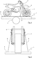
- Fig. 1 shows a transport device 1 for a two-wheeler 2, which has a chassis 3, a structural part 4 and a device 5 for holding the two-wheeler 2 on the structural part 4.
- the transport device 1 is a trailer, but it would also be possible to use a small transporter, a rail vehicle or the like as the transport device 1.
- the structural part 4 is designed as a base plate of the transport device 1.
- the two-wheeler 2 can also be attached to a lifting platform or the like with the device 5.
- the two-wheeler 2 which in this case is designed as an off-road motorcycle, is only to be regarded as an example and in principle any two-wheeler 2 can be attached to the structural part 4 with the device 5, whereby corresponding adaptations of the device 5 may be necessary.
- the device 5 is secured by means of several lashing elements 6, of which in Fig. 1 one is shown, connected to the structural part 4.
- Fig. 2 a schematic front view of the transport device 1 is shown, from which the arrangement of the device 5 relative to a fork 7 of the two-wheeler 2 can be seen.
- the point of application of the lashing elements 6, of which two are preferably provided, ie one on each side of the two-wheeler 2, is in the Figures 1 and 2 to recognize.
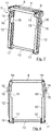
- the device 5 is shown in detail with its individual components.
- the device 5 has in its upper region a fork receiving element 8 which is in the Figures 3 , 6 and 7 has recognizable recesses 9 which are used to receive the fork 7 of the two-wheeler 2.
- the fork receiving element 8 is, as in particular in Fig. 5 can be seen, is designed in two parts and the recesses 9 are each semicircular, so that when the two parts of the fork receiving element 8 are arranged side by side, as in FIG Fig. 7 shown, result in two circular recesses 9 through which the fork 7 can be passed.
- Protective elements can be located in the recesses 9 in the fork receiving element 8, which elements can consist of felt, for example, and can be glued to the fork receiving element 8. Due to the protective elements, the fork receiving element 8 can be attached to the fork 7 without play and damage to the fork 7 is avoided at the same time.
- an axle support element 10 which serves to support the device 5 on an axle (not shown) of the front wheel of the two-wheeler 2.
- the axle is a hollow axle through which the axle support element 10, designed as a bolt, is passed.
- the axle support element can be locked in its position on both sides by means of respective locking pins 11 implemented in the same through corresponding bores.
- two vertically extending connecting elements 12 are used, which in the present case have recesses 13 designed as through-holes for receiving or, in the present case, for guiding the axle support element 10 through.
- the connecting elements 12 can be connected to the fork receiving element 8 on their upper side by means of respective connecting bolts 14.
- the connecting bolts 14 are preferably secured by means of respective locking pins, not shown.
- the securing pins for securing the connecting bolts 14 can be designed similarly to the securing pins 11 with which the axle support element 10 is locked in its position.
- screws can also be used can be used to connect the connecting elements 12 to the fork receiving elements 8.
- the use of the connecting bolts 14, however, enables the device 5 to be easily mounted on the two-wheeler 2.
- the connecting elements 12 On the connecting elements 12, respective devices 15 for attaching the lashing elements 6 are arranged.
- the devices 15 are arranged at a distance from the recesses 12 for leading the axle support element 10 through. As a result, a sufficiently high force application point of the lashing elements 6 on the device 5 is achieved.
- the connecting elements 12 have respective projections 16 in which the devices 15 for attaching the lashing elements 6 are arranged.
- the devices 15 are recesses into which hooks arranged on the lashing elements 6 can be inserted, for example.
- the devices 15 are arranged on the connecting elements 12, since the connecting elements 12 are particularly easily accessible. In principle, however, it would also be possible to attach the devices 15 for attaching the lashing elements 6 to the fork receiving element 8.
- respective spacer elements 17 are arranged to rest against the connecting elements 12 on the one hand and on the fork 7 of the two-wheeler 2 on the other hand.
- the connecting elements 12 have recesses 18 for adaptation to the shape of the fork 7 of the two-wheeler 2.
- the size and shape of the recesses 18 can be selected so that the connecting elements 12 are at a sufficient distance from the fork 7.
- the dimensions of the other components of the device 5 can also be adapted to different sizes or shapes of the respective two-wheeler 2.
- the device 5 can be used for very sporty-oriented motorcycles, which are mainly driven on racetracks, for so-called naked bikes or also for off-road or cross motorcycles.
- the outer diameter of the axle support element 10 can optionally be adapted to the inner diameter of the axle of the two-wheeler 2.
- the fork receiving element 8, the connecting elements 12 and possibly also the axle support element 10 can consist of an aluminum material. Of course, other materials can also be used for this.
- all parts of the device 5 are manufactured from a solid material by means of milling, but it would in principle also be possible to manufacture these parts by means of die casting or another suitable method. A combination of several methods is of course also conceivable.
Landscapes
- Engineering & Computer Science (AREA)
- Mechanical Engineering (AREA)
- Health & Medical Sciences (AREA)
- Public Health (AREA)
- Transportation (AREA)
- Packaging Of Machine Parts And Wound Products (AREA)
- Fittings On The Vehicle Exterior For Carrying Loads, And Devices For Holding Or Mounting Articles (AREA)
- Motorcycle And Bicycle Frame (AREA)
Description
- Die Erfindung betrifft eine Vorrichtung zur Halterung eines Zweirads an einem Strukturteil sowie eine Transportvorrichtung für ein Zweirad.
- Fahrer von Motorrädern oder anderen Zweirädern tendieren immer öfter dazu, mit ihrem Fahrzeug an weit entfernte Orte zu reisen. Häufig wird das Zweirad dabei auf eine ein Fahrwerk aufweisende Transportvorrichtung bzw. ein Transportfahrzeug verladen, da dem Benutzer die Fahrt zum Ziel entweder zu anstrengend ist oder das Zweirad für den öffentlichen Straßenverkehr gar nicht zugelassen ist, beispielsweise im Fall von Gelände- oder Rennsportmotorrädern.
- Das Verladen der Zweiräder ist meist mit einem hohen Aufwand verbunden, da dieselben auf zuverlässige Art und Weise mit dem Transportfahrzeug verbunden werden müssen, um Schäden während des Transports zu verhindern. Hierzu sind aus dem Stand der Technik die unterschiedlichsten Lösungen bekannt.
- In der
DE 20 2013 006 043 U1 ist eine Zurrvorrichtung als Ladungssicherung des Zweirads auf der Ladefläche eines Fahrzeugs beschrieben, bei der mehrere an dem Zweirad angreifende Zurrseile mittels jeweiliger Spindeln gespannt werden können. Im vorderen Bereich des Zweirads greifen diese Zurrseile beispielsweise am Lenker an und werden am Boden des Transportfahrzeugs eingehakt. Problematisch bei dieser Vorgehensweise ist jedoch die Tatsache, dass dabei die Federn des Zweirads sehr stark mit Kraft beaufschlagt und dadurch komprimiert werden, was grundsätzlich für die Haltbarkeit der Federn problematisch sein kann. Ein größeres Problem besteht jedoch darin, dass dies eine Kompression der Luftpolster in der Gabel bewirkt, wodurch das in der Gabel enthaltene Öl mit Druck beaufschlagt wird. Dieser Druck wird direkt auf die Dichtungselemente, in diesem Fall die Simmeringe, geleitet und führt bei dauerhafter Belastung, wie zum Beispiel bei einem längeren Transport, zur Undichtheit. Dies ist besonders dann sehr ärgerlich, wenn es erst am Zielort festgestellt wird, wo Reparaturen des Zweirads möglicherweise nicht oder nur zu sehr hohen Kosten möglich sind, sodass ein geplanter Urlaub möglicherweise nicht stattfinden kann. Insbesondere wenn ein solcher Transport des Zweirads gewerblich erfolgt, kann dies zu erheblichen Problemen führen. - Die
DE 20 2017 003 076 U1 beschreibt eine rollbare und verstellbare Motorrad-Verladehilfe, mit der das Motorrad an seinen beiden Rädern aufgenommen wird. Eine ähnliche Lösung ist auch aus derDE 10 2008 060 527 A1 bekannt. Ein grundsätzliches Problem bei der Aufnahme eines Zweirads im Bereich der Räder besteht allerdings darin, dass sich aufgrund der Höhe des Zweirads bei entsprechender Krafteinwirkung, beispielsweise bei Kurvenfahrten des Transportfahrzeugs, ein erhebliches Kippmoment ergibt, wodurch ein sicherer Transport des Zweirads praktisch nicht möglich ist. - Auch die in der
DE 20 2012 102 505 U1 und derEP 2 090 463 A2 beschriebenen Lösungen bringen ähnliche Probleme mit sich, da auch hier das Zweirad im Prinzip lediglich an einem oder beiden seiner Räder aufgenommen wird. - Die
FR 2 642 378 A1 - Aus der
US 2009/250564 A1 ist ein Motorradständer zum Lagern oder Transportieren eines Motorrades in einer unbeweglichen aufrechten Position bekannt. Dieser weist eine Ständerbasis auf, die mit einem Achsstützpfosten verbunden ist. - In der
US 4 441 736 A ist eine Fixiervorrichtung für Motorräder mit einem Paar relativ zueinander einstellbarer Streben beschrieben, die zwischen einem Teil eines Motorradchassis und einem Stützrad eingefügt werden können, um das Durchbiegen des Motorradaufhängungssystems zu blockieren, wenn das Motorrad auf einem Träger über unebenes Gelände oder dergleichen gezogen wird. - Es ist daher Aufgabe der vorliegenden Erfindung, eine Vorrichtung zur Halterung eines Zweirads an einem Strukturteil zu schaffen, die eine sichere Verbindung des Zweirads mit dem Strukturteil gewährleistet und Beschädigungen des Zweirads zuverlässig vermeidet.
- Erfindungsgemäß wird diese Aufgabe durch die in Anspruch 1 genannte Merkmale gelöst.
- Die erfindungsgemäße Vorrichtung bietet gegenüber bekannten Lösungen wesentliche Vorteile. So wird durch das Gabelaufnahmeelement eine sichere Verbindung der Vorrichtung mit dem Zweirad gewährleistet, wobei durch die Aufnahme des Zweirads im Bereich der Gabel und der damit verbundenen Möglichkeit eines hohen Kraftangriffpunkts gewährleistet ist, dass das Zweirad auch bei hohen auf dasselbe einwirkenden Kräften nicht kippen kann. Dies wird durch die zum Anbringen der Verzurrelemente dienenden Einrichtungen unterstützt, die sich ebenfalls in einem oberen Bereich des Zweirads befinden können, wodurch ein Kippen desselben zusätzlich verhindert wird.
- Durch diese direkt in die Vorrichtung integrierten Einrichtungen zum Anbringen der Verzurrelemente kann vorteilhafterweise darauf verzichtet werden, zum Verzurren notwendige Kräfte über die Gabel einzuleiten, sodass während des Transports auf die Gabelfedern wirkende Kräfte im Wesentlichen vermieden werden, was Beschädigungen des Zweirads und dessen Teile zuverlässig vermeidet.
- Die zuverlässige und sichere Aufnahme des Zweirads durch die erfindungsgemäße Vorrichtung wird durch das Achsenabstützelement unterstützt, da hierdurch eine starre Verbindung zwischen der Vorrichtung und dem Zweirad möglich ist, sodass entsprechend hohe Kräfte aufgenommen werden können. Dabei stellen die Verbindungselemente die Verbindung zwischen dem Gabelaufnahmeelement und dem Achsenabstützelement sicher und komplettieren damit die in Form eines Rahmens ausgebildete Vorrichtung.
- In einer sehr vorteilhaften Weiterbildung der Erfindung kann vorgesehen sein, dass die Einrichtungen zum Anbringen der Verzurrelemente an den Verbindungselementen angeordnet sind. Dadurch kann ein ausreichender Abstand zwischen den Einrichtungen zum Anbringen der Verzurrelemente und dem Achsenabstützelement geschaffen werden, sodass das Zweirad sicher mit dem entsprechenden Strukturteil verbunden werden kann.
- Wenn die Verbindungselemente jeweilige Vorsprünge aufweisen, an denen die Einrichtungen zum Anbringen der Verzurrelemente angeordnet sind, so ist es möglich, die Verbindungselemente einerseits ausreichend schmal und damit leicht auszuführen und andererseits in den für die Funktion der Vorrichtung wichtigen Bereichen dennoch eine ausreichende Festigkeit zu gewährleisten.
- Eine einfache Möglichkeit der Anbringung der Verzurrelemente an der erfindungsgemäßen Vorrichtung ergibt sich, wenn des Weiteren vorgesehen ist, dass die Einrichtungen zum Anbringen der Verzurrelemente als Ausnehmungen ausgebildet sind. Die Verzurrelemente können auf diese Weise zum Beispiel mittels entsprechender Haken oder ähnlichem in die Ausnehmungen eingehakt werden.
- Wenn das Gabelaufnahmeelement zweiteilig ausgebildet ist und die Ausnehmungen zum Aufnehmen der Gabel des Zweirads jeweils halbkreisförmig ausgebildet sind, so ergibt sich eine einfache Möglichkeit zur Montage des Gabelaufnahmeelementes an der Gabel.
- Des Weiteren kann vorgesehen sein, dass das Gabelaufnahmeelement mittels jeweiliger Verbindungsbolzen mit den Verbindungselementen verbunden ist. Dies ermöglicht eine einfache Montage der Verbindungselemente an dem Gabelaufnahmeelement und eine sichere Verbindung dieser Bauteile.
- Um die Vorrichtung dauerhaft und sicher in ihrer das Zweirad fixierenden Stellung zu halten, kann des Weiteren vorgesehen sein, dass die Verbindungsbolzen mittels jeweiliger Sicherungsstifte gesichert sind.
- Eine einfache Ausführung des Achsenabstützelements ergibt sich, wenn dasselbe als durch die Achse des Zweirads hindurchführbarer Bolzen ausgebildet ist. Auf diese Weise ist außerdem eine einfache Montage der Vorrichtung möglich.
- Dabei kann vorgesehen sein, dass das Achsenabstützelement mittels jeweiliger Sicherungsstifte in seiner Position arretierbar ist. Dies ermöglicht auf einfache Weise ein sicheres Fixieren der Vorrichtung in ihrer das Zweirad haltenden Position.
- Um eine Anpassung der Vorrichtung an unterschiedliche Ausführungen von Zweirädern zu ermöglichen, kann des Weiteren vorgesehen sein, dass auf dem Achsenabstützelement Abstandselemente zur Anlage an den Verbindungselementen und an der Gabel des Zweirads angeordnet sind.
- Wenn in den Ausnehmungen in dem Gabelaufnahmeelement jeweilige Schutzelemente angeordnet sind, so werden Beschädigungen der Gabel in jeder Phase während des Transports des Zweirads mit der erfindungsgemäßen Vorrichtung verhindert.
- Eine einfache Ausführungsform dieser Schutzelemente ergibt sich, wenn dieselben aus Filz bestehen und mit dem Gabelaufnahmeelement verklebt sind.
- Eine weitere Anpassung der Vorrichtung an unterschiedliche Ausgestaltungen von Zweirädern kann sich ergeben, wenn die Verbindungselemente jeweilige Aussparungen zur Anpassung an die Form der Gabel des Zweirads aufweisen.
- Eine weitere vorteilhafte Ausgestaltung der Erfindung kann darin bestehen, dass zumindest das Gabelaufnahmeelement und die Verbindungselemente aus einem Aluminiumwerkstoff bestehen. Dadurch wird eine leichte, robuste und vor Korrosion geschützte Ausführung der Vorrichtung erreicht.
- In Anspruch 15 ist eine Transportvorrichtung für ein Zweirad mit einem Fahrwerk, einem Strukturteil und einer erfindungsgemäßen Vorrichtung angegeben.
- Mittels dieser Transportvorrichtung können Zweiräder einfach und sicher an unterschiedliche Orte transportiert werden.
- Nachfolgend ist ein Ausführungsbeispiel der Erfindung anhand der Zeichnung prinzipmäßig dargestellt.
- Es zeigt:
- Fig. 1
- eine sehr schematische Ansicht einer erfindungsgemäßen Transportvorrichtung;
- Fig. 2
- eine schematische Vorderansicht der Transportvorrichtung;
- Fig. 3
- eine perspektivische Ansicht der erfindungsgemäßen Vorrichtung;
- Fig. 4
- eine Vorderansicht der erfindungsgemäßen Vorrichtung;
- Fig. 5
- eine Seitenansicht der erfindungsgemäßen Vorrichtung;
- Fig. 6
- eine Ansicht der erfindungsgemäßen Vorrichtung von unten; und
- Fig. 7
- eine Draufsicht auf die erfindungsgemäße Vorrichtung.
-
Fig. 1 zeigt eine Transportvorrichtung 1 für ein Zweirad 2, die ein Fahrwerk 3, ein Strukturteil 4 sowie eine Vorrichtung 5 zur Halterung des Zweirads 2 an dem Strukturteil 4 aufweist. Bei der Transportvorrichtung 1 handelt es sich im vorliegenden Fall um einen Anhänger, es wäre jedoch auch möglich, einen Kleintransporter, ein Schienenfahrzeug oder ähnliches als die Transportvorrichtung 1 einzusetzen. Des Weiteren ist das Strukturteil 4 als Bodenplatte der Transportvorrichtung 1 ausgebildet. Auch hier wäre es möglich, andere Strukturteile einzusetzen, um das Zweirad mit Hilfe der Vorrichtung 5 an denselben anzubringen. Beispielsweise lässt sich mit der Vorrichtung 5 das Zweirad 2 auch auf einer Hebebühne oder ähnlichem befestigen. - Auch das Zweirad 2, das in diesem Fall als Geländemotorrad ausgebildet ist, ist lediglich als beispielhaft anzusehen und es kann mit der Vorrichtung 5 im Prinzip jedes beliebige Zweirad 2 an dem Strukturteil 4 angebracht werden, wobei entsprechende Anpassungen der Vorrichtung 5 erforderlich sein können.
- Die Vorrichtung 5 wird mittels mehrerer Verzurrelemente 6, von denen in
Fig. 1 eines dargestellt ist, mit dem Strukturteil 4 verbunden. InFig. 2 ist eine schematische Vorderansicht der Transportvorrichtung 1 dargestellt, aus der die Anordnung der Vorrichtung 5 gegenüber einer Gabel 7 des Zweirads 2 erkennbar ist. Auch der Angriffspunkt der Verzurrelemente 6, von denen vorzugsweise zwei, also eines auf jeder Seite des Zweirads 2, vorgesehen sind, ist in denFiguren 1 und 2 zu erkennen. - In den
Figuren 3 bis 7 ist die Vorrichtung 5 mit ihren einzelnen Bauteilen detailliert dargestellt. Die Vorrichtung 5 weist in ihrem oberen Bereich ein Gabelaufnahmeelement 8 auf, das in denFiguren 3 ,6 und 7 erkennbare Ausnehmungen 9 aufweist, die zum Aufnehmen der Gabel 7 des Zweirads 2 dienen. Das Gabelaufnahmeelement 8 ist, wie insbesondere inFig. 5 erkennbar ist, zweiteilig ausgebildet und die Ausnehmungen 9 sind jeweils halbkreisförmig ausgebildet, so dass sich bei der Anordnung der beiden Teile des Gabelaufnahmeelements 8 nebeneinander, wie inFig. 7 dargestellt, zwei kreisförmige Ausnehmungen 9 ergeben, durch welche die Gabel 7 hindurchgeführt werden kann. - Bei der Montage des Gabelaufnahmeelements 8 an der Gabel 7 werden die beiden Teile des Gabelaufnahmeelements 8 von beiden Seiten zusammengeführt, wobei die Gabel 7 sich zwischen denselben befindet, sodass die beiden Holme der Gabel 7 in den beiden Ausnehmungen 9 aufgenommen sind.
- In den Ausnehmungen 9 in dem Gabelaufnahmeelement 8 können sich nicht dargestellte Schutzelemente befinden, die zum Beispiel aus Filz bestehen können und mit dem Gabelaufnahmeelement 8 verklebt werden können. Durch die Schutzelemente kann das Gabelaufnahmeelement 8 ohne Spiel an der Gabel 7 angebracht werden und es werden gleichzeitig Beschädigungen der Gabel 7 vermieden.
- Auf der dem Gabelaufnahmeelement 8 gegenüberliegenden Seite, also auf der Unterseite der Vorrichtung 5, ist ein Achsenabstützelement 10 vorgesehen, das zum Abstützen der Vorrichtung 5 an einer nicht dargestellten Achse des Vorderrads des Zweirads 2 dient. Bei der Achse handelt es sich im vorliegenden Fall um eine Hohlachse, durch die das als Bolzen ausgebildete Achsenabstützelement 10 hindurchgeführt wird. Das Achsenabstützelement kann auf beiden Seiten mittels jeweilige, durch entsprechende Bohrungen in demselben durchgeführte Sicherungsstifte 11 in seiner Position arretiert werden.
- Zur Verbindung des Gabelaufnahmeelements 8 mit dem Achsenabstützelement 10 dienen zwei in vertikaler Richtung verlaufende Verbindungselemente 12, die jeweilige, im vorliegenden Fall als Durchgangsbohrungen ausgebildete Ausnehmungen 13 zum Aufnehmen bzw. im vorliegenden Fall zum Hindurchführen des Achsenabstützelements 10 aufweisen. Die Verbindungselemente 12 können an ihrer Oberseite mittels jeweiliger Verbindungsbolzen 14 mit dem Gabelaufnahmeelement 8 verbunden werden. Die Verbindungsbolzen 14 sind vorzugsweise mittels jeweiliger, nicht dargestellter Sicherungsstifte gesichert. Die Sicherungsstifte zur Sicherung der Verbindungsbolzen 14 können ähnlich zu den Sicherungsstiften 11 ausgebildet sein, mit denen das Achsenabstützelement 10 in seiner Position arretiert wird. Statt der Verbindungsbolzen 14 können auch Schrauben eingesetzt werden, um die Verbindungselemente 12 mit den Gabelaufnahmeelementen 8 zu verbinden. Die Verwendung der Verbindungsbolzen 14 ermöglicht jedoch eine einfache Montage der Vorrichtung 5 an dem Zweirad 2.
- An den Verbindungselementen 12 sind jeweilige Einrichtungen 15 zum Anbringen der Verzurrelemente 6 angeordnet. Die Einrichtungen 15 sind von den Ausnehmungen 12 zum Durchführen des Achsenabstützelements 10 entfernt angeordnet. Dadurch wird ein ausreichend hoher Kraftangriffspunkt der Verzurrelemente 6 an der Vorrichtung 5 erreicht. Im dargestellten Ausführungsbeispiel weisen die Verbindungselemente 12 jeweilige Vorsprünge 16 auf, in denen die Einrichtungen 15 zum Anbringen der Verzurrelemente 6 angeordnet sind. Bei den Einrichtungen 15 handelt es sich im vorliegenden Fall um Ausnehmungen, in die zum Beispiel an den Verzurrelementen 6 angeordnete Haken eingeführt werden können.
- Im vorliegenden Fall sind die Einrichtungen 15 an den Verbindungselementen 12 angeordnet, da die Verbindungselemente 12 besonders einfach zugänglich sind. Grundsätzlich wäre es jedoch auch möglich, die Einrichtungen 15 zum Anbringen der Verzurrelemente 6 an dem Gabelaufnahmeelement 8 anzubringen.
- Auf dem Achsenabstützelement 10 sind jeweilige Abstandselemente 17 zur Anlage an den Verbindungselementen 12 einerseits und an der Gabel 7 des Zweirads 2 andererseits angeordnet. Durch die Abstandselemente 17, die jeweilige Bohrungen zum Durchführen des Achsenabstützelements 10 aufweisen, wird eventuell vorhandenes Spiel zwischen den Bauteilen herausgenommen.
- Die Verbindungselemente 12 weisen im vorliegenden Fall Aussparungen 18 zur Anpassung an die Form der Gabel 7 des Zweirads 2 auf. Die Größe und Form der Aussparungen 18 kann so gewählt werden, dass die Verbindungselemente 12 einen ausreichenden Abstand von der Gabel 7 aufweisen. Selbstverständlich können auch die Maße der weiteren Bauteile der Vorrichtung 5 an unterschiedliche Größen bzw. Formen des jeweiligen Zweirads 2 angepasst werden. Auf diese Weise lässt sich die Vorrichtung 5 für sehr sportlich orientierte Motorräder, die hauptsächlich auf Rennstrecken gefahren werden, für sogenannte Naked Bikes oder auch für Gelände- bzw. Cross-Motorräder einsetzen. Beispielsweise kann es für Geländemotorräder oder Naked Bikes erforderlich sein, die Verbindungselemente 12 länger auszuführen als bei Sport- bzw. Rennmotorrädern. Des Weiteren kann gegebenenfalls der Außendurchmesser des Achsenabstützelements 10 an den Innendurchmesser der Achse des Zweirads 2 angepasst werden.
- Das Gabelaufnahmeelemente 8, die Verbindungselemente 12 und gegebenenfalls auch das Achsenabstützelement 10 können aus einem Aluminiumwerkstoff bestehen. Selbstverständlich können auch andere Werkstoffe hierfür eingesetzt werden.
- Im vorliegenden Fall sind sämtliche Teile der Vorrichtung 5 mittels Fräsen aus einem Vollmaterial hergestellt, es wäre jedoch grundsätzlich auch möglich, diese Teile mittels Druckgießen oder einem anderen geeigneten Verfahren herzustellen. Auch eine Kombination mehrerer Verfahren ist selbstverständlich denkbar.
Claims (15)
- Vorrichtung (5) zur Halterung eines Zweirads (2) an einem Strukturteil (4), mit folgenden Merkmalen:- einem Gabelaufnahmeelement (8), das Ausnehmungen (9) zum Aufnehmen einer Gabel (7) des Zweirads (2) aufweist,- einem Achsenabstützelement (10) zum Abstützen an einer Achse des Zweirads (2),
gekennzeichnet durch- wenigstens zwei Verbindungselementen (12) zum Verbinden des Gabelaufnahmeelements (8) mit dem Achsenabstützelement (10), die jeweilige Ausnehmungen (13) zum Aufnehmen des Achsenabstützelements (10) aufweisen, und- wenigstens zwei von den Ausnehmungen (13) zum Aufnehmen des Achsenabstützelements (10) beabstandeten Einrichtungen (15) zum Anbringen von Verzurrelementen (6), mit denen die Vorrichtung (5) mit dem Strukturteil (4) verbindbar ist. - Vorrichtung nach Anspruch 1,
dadurch gekennzeichnet, dass
die Einrichtungen (15) zum Anbringen der Verzurrelemente (6) an den Verbindungselementen (12) angeordnet sind. - Vorrichtung nach Anspruch 2,
dadurch gekennzeichnet, dass
die Verbindungselemente (12) jeweilige Vorsprünge (16) aufweisen, an denen die Einrichtungen (15) zum Anbringen der Verzurrelemente (6) angeordnet sind. - Vorrichtung nach Anspruch 1, 2 oder 3,
dadurch gekennzeichnet, dass
die Einrichtungen (15) zum Anbringen der Verzurrelemente (6) als Ausnehmungen ausgebildet sind. - Vorrichtung nach einem der Ansprüche 1 bis 4,
dadurch gekennzeichnet, dass
das Gabelaufnahmeelement (8) zweiteilig ausgebildet ist, wobei die Ausnehmungen (9) zum Aufnehmen der Gabel (7) des Zweirads (2) jeweils halbkreisförmig ausgebildet sind. - Vorrichtung nach einem der Ansprüche 1 bis 5,
dadurch gekennzeichnet, dass
das Gabelaufnahmeelement (8) mittels jeweiliger Verbindungsbolzen (14) mit den Verbindungselementen (12) verbunden ist. - Vorrichtung nach Anspruch 6,
dadurch gekennzeichnet, dass
die Verbindungsbolzen (14) mittels jeweiliger Sicherungsstifte gesichert sind. - Vorrichtung nach einem der Ansprüche 1 bis 7,
dadurch gekennzeichnet, dass
das Achsenabstützelement (10) als durch die Achse des Zweirads (2) hindurchführbarer Bolzen ausgebildet ist. - Vorrichtung nach Anspruch 8,
dadurch gekennzeichnet, dass
das Achsenabstützelement (10) mittels jeweiliger Sicherungsstifte (11) in seiner Position arretierbar ist. - Vorrichtung nach Anspruch 8 oder 9,
dadurch gekennzeichnet, dass
auf dem Achsenabstützelement (10) Abstandselemente (17) zur Anlage an den Verbindungselementen (12) und an der Gabel (7) des Zweirads (2) angeordnet sind. - Vorrichtung nach einem der Ansprüche 1 bis 10,
dadurch gekennzeichnet, dass
in den Ausnehmungen (9) in dem Gabelaufnahmeelement (8) jeweilige Schutzelemente angeordnet sind. - Vorrichtung nach Anspruch 11,
dadurch gekennzeichnet, dass
die Schutzelemente aus Filz bestehen und mit dem Gabelaufnahmeelement (8) verklebt sind. - Vorrichtung nach einem der Ansprüche 1 bis 12,
dadurch gekennzeichnet, dass
die Verbindungselemente (12) jeweilige Aussparungen (18) zur Anpassung an die Form der Gabel (7) des Zweirads (2) aufweisen. - Vorrichtung nach einem der Ansprüche 1 bis 13,
dadurch gekennzeichnet, dass
zumindest das Gabelaufnahmeelement (8) und die Verbindungselemente (12) aus einem Aluminiumwerkstoff bestehen. - Transportvorrichtung (1) für ein Zweirad (2), mit einem Fahrwerk (3), mit einem Strukturteil (4), mit einer Vorrichtung (5) nach einem der Ansprüche 1 bis 14 und mit Verzurrelementen (6), die mit den Einrichtungen (15) zum Anbringen derselben in Eingriff sind und mit denen die Vorrichtung (5) mit dem Strukturteil (4) verbunden ist.
Applications Claiming Priority (2)
| Application Number | Priority Date | Filing Date | Title |
|---|---|---|---|
| DE202018100033.0U DE202018100033U1 (de) | 2018-01-03 | 2018-01-03 | Vorrichtung zur Halterung eines Zweirads an einem Strukturteil |
| PCT/EP2019/050009 WO2019134901A1 (de) | 2018-01-03 | 2019-01-02 | Vorrichtung zur halterung eines zweirads an einem strukturteil |
Publications (3)
| Publication Number | Publication Date |
|---|---|
| EP3609740A1 EP3609740A1 (de) | 2020-02-19 |
| EP3609740B1 true EP3609740B1 (de) | 2020-08-26 |
| EP3609740B8 EP3609740B8 (de) | 2020-11-11 |
Family
ID=61525812
Family Applications (1)
| Application Number | Title | Priority Date | Filing Date |
|---|---|---|---|
| EP19700194.4A Active EP3609740B8 (de) | 2018-01-03 | 2019-01-02 | Vorrichtung zur halterung eines zweirads an einem strukturteil |
Country Status (5)
| Country | Link |
|---|---|
| US (1) | US11383778B2 (de) |
| EP (1) | EP3609740B8 (de) |
| DE (1) | DE202018100033U1 (de) |
| ES (1) | ES2834647T3 (de) |
| WO (1) | WO2019134901A1 (de) |
Families Citing this family (2)
| Publication number | Priority date | Publication date | Assignee | Title |
|---|---|---|---|---|
| DE102022104407A1 (de) | 2022-02-24 | 2023-08-24 | Bayerische Motoren Werke Aktiengesellschaft | Haltevorrichtung zum Halten eines Zweirads auf einem Untergrund |
| DE102022108128A1 (de) | 2022-04-05 | 2023-10-05 | Bayerische Motoren Werke Aktiengesellschaft | Haltevorrichtung zum Halten eines Zweirads auf einem Untergrund |
Family Cites Families (10)
| Publication number | Priority date | Publication date | Assignee | Title |
|---|---|---|---|---|
| US4441736A (en) * | 1982-05-12 | 1984-04-10 | Shedden Joel T | Device for reducing wear in vehicle suspension systems |
| FR2642378B1 (fr) * | 1989-02-02 | 1991-06-14 | Bockler Didier | Dispositif de fixation rapide de motocyclettes sur une remorque de transport |
| US8485369B2 (en) * | 2007-12-18 | 2013-07-16 | Woodrow Loyd Glover | Motorcycle stand |
| AT505287B1 (de) | 2008-02-12 | 2008-12-15 | Oebb Personenverkehr Ag | Motorradbefestigung |
| DE102008060527A1 (de) | 2008-12-04 | 2010-04-29 | Daimler Ag | Haltevorrichtung und Anordnung einer Haltevorrichtung zur Halterung eines Rades, insbesondere eines Kraftrades, an einem Ladeboden eines Fahrzeugs |
| US8517343B1 (en) * | 2012-02-07 | 2013-08-27 | Pit Bull Products, Inc. | Dual purpose front motorcycle stand |
| DE102012101192A1 (de) * | 2012-02-15 | 2013-08-22 | Matthias Müller | Anordnung zum Festhalten eines Zweiradfahrzeugs auf einem Transportfahrzeug |
| DE202012102505U1 (de) | 2012-07-06 | 2012-08-06 | Aceproducts B.V. | Motorradständer zum Feststellen eines Motorrades |
| DE202013006043U1 (de) | 2013-07-05 | 2013-12-05 | Stefan Wenner | Zurrvorrichtung für Motorräder auf Anhängern |
| DE202017003076U1 (de) | 2017-06-10 | 2017-10-11 | Dirk Müller | Rollbare und verstellbare Motorrad Verladehilfe |
-
2018
- 2018-01-03 DE DE202018100033.0U patent/DE202018100033U1/de active Active
-
2019
- 2019-01-02 ES ES19700194T patent/ES2834647T3/es active Active
- 2019-01-02 WO PCT/EP2019/050009 patent/WO2019134901A1/de not_active Ceased
- 2019-01-02 US US16/959,518 patent/US11383778B2/en active Active
- 2019-01-02 EP EP19700194.4A patent/EP3609740B8/de active Active
Non-Patent Citations (1)
| Title |
|---|
| None * |
Also Published As
| Publication number | Publication date |
|---|---|
| WO2019134901A1 (de) | 2019-07-11 |
| DE202018100033U1 (de) | 2018-01-17 |
| US11383778B2 (en) | 2022-07-12 |
| ES2834647T3 (es) | 2021-06-18 |
| EP3609740B8 (de) | 2020-11-11 |
| EP3609740A1 (de) | 2020-02-19 |
| US20210053634A1 (en) | 2021-02-25 |
Similar Documents
| Publication | Publication Date | Title |
|---|---|---|
| EP2158120A1 (de) | Schaltauge mit einsetzhilfe | |
| EP3609740B1 (de) | Vorrichtung zur halterung eines zweirads an einem strukturteil | |
| DE102013215063A1 (de) | Innenausstattungsgegenstand zur Anordnung in Fahrzeugen des öffentlichen Verkehrs | |
| DE202013011014U1 (de) | Kraftfahrzeug mit Fixierungseinrichtung für ein Fahrrad | |
| DE4429788C2 (de) | Vorrichtung zum Befestigen einer Plattform an der Kupplungskugel einer Anhängevorrichtung eines Kraftwagens | |
| DE202015003646U1 (de) | Fahrrad-Halterung als Ladungssicherung für den Transport von Fahrrädern im Innern eines Kraftfahrzeugs | |
| DE102004044246A1 (de) | Lasterträger für Kraftfahrzeuge | |
| EP2998158B1 (de) | Lochblechfahrbahn | |
| DE102005000081A1 (de) | Tambourwagen | |
| DE102011010578A1 (de) | Vorrichtung zur Befestigung eines Fahrrades in einem Fahrzeuginnenraum | |
| DE202016006976U1 (de) | Halterung für den gesicherten Transport von Ladung im Innern eines Kraftfahrzeuges | |
| DE102019209580A1 (de) | Ladesystem zur Aufnahme eines mit Rädern versehenen Gegenstands | |
| DE102011106869A1 (de) | Lastenträgervorrichtung, vorzugsweise für einen Personenkraftwagen | |
| DE19744233C2 (de) | Abschwenkbare Reserveradhalterung eines Sicherheitskraftfahrzeuges für die Beförderung sperriger Güter | |
| DE102013107302B4 (de) | Zweirad mit einem Trittbrett | |
| DE102021204801A1 (de) | Fahrradanhängeranordnung | |
| EP4059818A1 (de) | Halter und haltevorrichtung für zweiräder | |
| DE202010016094U1 (de) | Fahrradtaschenhalter | |
| DE202017103729U1 (de) | Personen-, Lasten- und Transportroller | |
| DE20118084U1 (de) | Fahrradzentralverriegelung | |
| DE102010046668A1 (de) | Mehrteiliger Fahrradträger, der in eine an der Rückseite eines Kraftfahrzeuges abschwenkbar befestigte Halterung einsetzbar ist | |
| DE102013018169B4 (de) | Fahrrad mit zumindest einem daran befestigten Beiwagen | |
| DE102019133768A1 (de) | Halteelement für Lasten an einem Zweirad, insbesondere an einem Rollerfahrzeug, und Zweirad, insbesondere Rollerfahrzeug | |
| DE102014002794A1 (de) | Vorrichtung zur Befestigung eines Lastenträgers | |
| DE212016000078U1 (de) | Radständer |
Legal Events
| Date | Code | Title | Description |
|---|---|---|---|
| STAA | Information on the status of an ep patent application or granted ep patent |
Free format text: STATUS: UNKNOWN |
|
| STAA | Information on the status of an ep patent application or granted ep patent |
Free format text: STATUS: THE INTERNATIONAL PUBLICATION HAS BEEN MADE |
|
| PUAI | Public reference made under article 153(3) epc to a published international application that has entered the european phase |
Free format text: ORIGINAL CODE: 0009012 |
|
| STAA | Information on the status of an ep patent application or granted ep patent |
Free format text: STATUS: REQUEST FOR EXAMINATION WAS MADE |
|
| 17P | Request for examination filed |
Effective date: 20191114 |
|
| AK | Designated contracting states |
Kind code of ref document: A1 Designated state(s): AL AT BE BG CH CY CZ DE DK EE ES FI FR GB GR HR HU IE IS IT LI LT LU LV MC MK MT NL NO PL PT RO RS SE SI SK SM TR |
|
| AX | Request for extension of the european patent |
Extension state: BA ME |
|
| GRAP | Despatch of communication of intention to grant a patent |
Free format text: ORIGINAL CODE: EPIDOSNIGR1 |
|
| STAA | Information on the status of an ep patent application or granted ep patent |
Free format text: STATUS: GRANT OF PATENT IS INTENDED |
|
| DAV | Request for validation of the european patent (deleted) | ||
| DAX | Request for extension of the european patent (deleted) | ||
| INTG | Intention to grant announced |
Effective date: 20200612 |
|
| GRAS | Grant fee paid |
Free format text: ORIGINAL CODE: EPIDOSNIGR3 |
|
| GRAA | (expected) grant |
Free format text: ORIGINAL CODE: 0009210 |
|
| STAA | Information on the status of an ep patent application or granted ep patent |
Free format text: STATUS: THE PATENT HAS BEEN GRANTED |
|
| TPAC | Observations filed by third parties |
Free format text: ORIGINAL CODE: EPIDOSNTIPA |
|
| AK | Designated contracting states |
Kind code of ref document: B1 Designated state(s): AL AT BE BG CH CY CZ DE DK EE ES FI FR GB GR HR HU IE IS IT LI LT LU LV MC MK MT NL NO PL PT RO RS SE SI SK SM TR |
|
| REG | Reference to a national code |
Ref country code: GB Ref legal event code: FG4D Free format text: NOT ENGLISH |
|
| REG | Reference to a national code |
Ref country code: CH Ref legal event code: EP |
|
| REG | Reference to a national code |
Ref country code: DE Ref legal event code: R096 Ref document number: 502019000178 Country of ref document: DE |
|
| GRAT | Correction requested after decision to grant or after decision to maintain patent in amended form |
Free format text: ORIGINAL CODE: EPIDOSNCDEC |
|
| REG | Reference to a national code |
Ref country code: AT Ref legal event code: REF Ref document number: 1306070 Country of ref document: AT Kind code of ref document: T Effective date: 20200915 |
|
| REG | Reference to a national code |
Ref country code: IE Ref legal event code: FG4D Free format text: LANGUAGE OF EP DOCUMENT: GERMAN |
|
| REG | Reference to a national code |
Ref country code: CH Ref legal event code: PK Free format text: BERICHTIGUNGEN |
|
| RIN2 | Information on inventor provided after grant (corrected) |
Inventor name: KOELBL, RONNY |
|
| REG | Reference to a national code |
Ref country code: CH Ref legal event code: PK Free format text: BERICHTIGUNG B8 |
|
| REG | Reference to a national code |
Ref country code: CH Ref legal event code: NV Representative=s name: VALIPAT S.A. C/O BOVARD SA NEUCHATEL, CH |
|
| REG | Reference to a national code |
Ref country code: NL Ref legal event code: FP |
|
| REG | Reference to a national code |
Ref country code: LT Ref legal event code: MG4D |
|
| PG25 | Lapsed in a contracting state [announced via postgrant information from national office to epo] |
Ref country code: LT Free format text: LAPSE BECAUSE OF FAILURE TO SUBMIT A TRANSLATION OF THE DESCRIPTION OR TO PAY THE FEE WITHIN THE PRESCRIBED TIME-LIMIT Effective date: 20200826 Ref country code: PT Free format text: LAPSE BECAUSE OF FAILURE TO SUBMIT A TRANSLATION OF THE DESCRIPTION OR TO PAY THE FEE WITHIN THE PRESCRIBED TIME-LIMIT Effective date: 20201228 Ref country code: NO Free format text: LAPSE BECAUSE OF FAILURE TO SUBMIT A TRANSLATION OF THE DESCRIPTION OR TO PAY THE FEE WITHIN THE PRESCRIBED TIME-LIMIT Effective date: 20201126 Ref country code: HR Free format text: LAPSE BECAUSE OF FAILURE TO SUBMIT A TRANSLATION OF THE DESCRIPTION OR TO PAY THE FEE WITHIN THE PRESCRIBED TIME-LIMIT Effective date: 20200826 Ref country code: BG Free format text: LAPSE BECAUSE OF FAILURE TO SUBMIT A TRANSLATION OF THE DESCRIPTION OR TO PAY THE FEE WITHIN THE PRESCRIBED TIME-LIMIT Effective date: 20201126 Ref country code: FI Free format text: LAPSE BECAUSE OF FAILURE TO SUBMIT A TRANSLATION OF THE DESCRIPTION OR TO PAY THE FEE WITHIN THE PRESCRIBED TIME-LIMIT Effective date: 20200826 Ref country code: SE Free format text: LAPSE BECAUSE OF FAILURE TO SUBMIT A TRANSLATION OF THE DESCRIPTION OR TO PAY THE FEE WITHIN THE PRESCRIBED TIME-LIMIT Effective date: 20200826 |
|
| PG25 | Lapsed in a contracting state [announced via postgrant information from national office to epo] |
Ref country code: LV Free format text: LAPSE BECAUSE OF FAILURE TO SUBMIT A TRANSLATION OF THE DESCRIPTION OR TO PAY THE FEE WITHIN THE PRESCRIBED TIME-LIMIT Effective date: 20200826 Ref country code: PL Free format text: LAPSE BECAUSE OF FAILURE TO SUBMIT A TRANSLATION OF THE DESCRIPTION OR TO PAY THE FEE WITHIN THE PRESCRIBED TIME-LIMIT Effective date: 20200826 Ref country code: RS Free format text: LAPSE BECAUSE OF FAILURE TO SUBMIT A TRANSLATION OF THE DESCRIPTION OR TO PAY THE FEE WITHIN THE PRESCRIBED TIME-LIMIT Effective date: 20200826 Ref country code: IS Free format text: LAPSE BECAUSE OF FAILURE TO SUBMIT A TRANSLATION OF THE DESCRIPTION OR TO PAY THE FEE WITHIN THE PRESCRIBED TIME-LIMIT Effective date: 20201226 |
|
| PG25 | Lapsed in a contracting state [announced via postgrant information from national office to epo] |
Ref country code: SM Free format text: LAPSE BECAUSE OF FAILURE TO SUBMIT A TRANSLATION OF THE DESCRIPTION OR TO PAY THE FEE WITHIN THE PRESCRIBED TIME-LIMIT Effective date: 20200826 Ref country code: EE Free format text: LAPSE BECAUSE OF FAILURE TO SUBMIT A TRANSLATION OF THE DESCRIPTION OR TO PAY THE FEE WITHIN THE PRESCRIBED TIME-LIMIT Effective date: 20200826 Ref country code: CZ Free format text: LAPSE BECAUSE OF FAILURE TO SUBMIT A TRANSLATION OF THE DESCRIPTION OR TO PAY THE FEE WITHIN THE PRESCRIBED TIME-LIMIT Effective date: 20200826 Ref country code: DK Free format text: LAPSE BECAUSE OF FAILURE TO SUBMIT A TRANSLATION OF THE DESCRIPTION OR TO PAY THE FEE WITHIN THE PRESCRIBED TIME-LIMIT Effective date: 20200826 Ref country code: RO Free format text: LAPSE BECAUSE OF FAILURE TO SUBMIT A TRANSLATION OF THE DESCRIPTION OR TO PAY THE FEE WITHIN THE PRESCRIBED TIME-LIMIT Effective date: 20200826 |
|
| REG | Reference to a national code |
Ref country code: DE Ref legal event code: R097 Ref document number: 502019000178 Country of ref document: DE |
|
| PG25 | Lapsed in a contracting state [announced via postgrant information from national office to epo] |
Ref country code: AL Free format text: LAPSE BECAUSE OF FAILURE TO SUBMIT A TRANSLATION OF THE DESCRIPTION OR TO PAY THE FEE WITHIN THE PRESCRIBED TIME-LIMIT Effective date: 20200826 |
|
| REG | Reference to a national code |
Ref country code: ES Ref legal event code: FG2A Ref document number: 2834647 Country of ref document: ES Kind code of ref document: T3 Effective date: 20210618 |
|
| PG25 | Lapsed in a contracting state [announced via postgrant information from national office to epo] |
Ref country code: SK Free format text: LAPSE BECAUSE OF FAILURE TO SUBMIT A TRANSLATION OF THE DESCRIPTION OR TO PAY THE FEE WITHIN THE PRESCRIBED TIME-LIMIT Effective date: 20200826 |
|
| PLBE | No opposition filed within time limit |
Free format text: ORIGINAL CODE: 0009261 |
|
| STAA | Information on the status of an ep patent application or granted ep patent |
Free format text: STATUS: NO OPPOSITION FILED WITHIN TIME LIMIT |
|
| 26N | No opposition filed |
Effective date: 20210527 |
|
| PG25 | Lapsed in a contracting state [announced via postgrant information from national office to epo] |
Ref country code: MC Free format text: LAPSE BECAUSE OF FAILURE TO SUBMIT A TRANSLATION OF THE DESCRIPTION OR TO PAY THE FEE WITHIN THE PRESCRIBED TIME-LIMIT Effective date: 20200826 |
|
| PG25 | Lapsed in a contracting state [announced via postgrant information from national office to epo] |
Ref country code: IE Free format text: LAPSE BECAUSE OF NON-PAYMENT OF DUE FEES Effective date: 20210102 |
|
| PGFP | Annual fee paid to national office [announced via postgrant information from national office to epo] |
Ref country code: LU Payment date: 20220120 Year of fee payment: 4 |
|
| PGFP | Annual fee paid to national office [announced via postgrant information from national office to epo] |
Ref country code: CH Payment date: 20220125 Year of fee payment: 4 |
|
| PGFP | Annual fee paid to national office [announced via postgrant information from national office to epo] |
Ref country code: NL Payment date: 20220120 Year of fee payment: 4 Ref country code: IT Payment date: 20220131 Year of fee payment: 4 Ref country code: FR Payment date: 20220117 Year of fee payment: 4 Ref country code: ES Payment date: 20220216 Year of fee payment: 4 Ref country code: BE Payment date: 20220120 Year of fee payment: 4 |
|
| P01 | Opt-out of the competence of the unified patent court (upc) registered |
Effective date: 20230512 |
|
| PG25 | Lapsed in a contracting state [announced via postgrant information from national office to epo] |
Ref country code: CY Free format text: LAPSE BECAUSE OF FAILURE TO SUBMIT A TRANSLATION OF THE DESCRIPTION OR TO PAY THE FEE WITHIN THE PRESCRIBED TIME-LIMIT Effective date: 20200826 |
|
| PG25 | Lapsed in a contracting state [announced via postgrant information from national office to epo] |
Ref country code: HU Free format text: LAPSE BECAUSE OF FAILURE TO SUBMIT A TRANSLATION OF THE DESCRIPTION OR TO PAY THE FEE WITHIN THE PRESCRIBED TIME-LIMIT; INVALID AB INITIO Effective date: 20190102 Ref country code: GR Free format text: LAPSE BECAUSE OF FAILURE TO SUBMIT A TRANSLATION OF THE DESCRIPTION OR TO PAY THE FEE WITHIN THE PRESCRIBED TIME-LIMIT Effective date: 20200826 |
|
| REG | Reference to a national code |
Ref country code: CH Ref legal event code: PL |
|
| REG | Reference to a national code |
Ref country code: NL Ref legal event code: MM Effective date: 20230201 |
|
| GBPC | Gb: european patent ceased through non-payment of renewal fee |
Effective date: 20230102 |
|
| PG25 | Lapsed in a contracting state [announced via postgrant information from national office to epo] |
Ref country code: SI Free format text: LAPSE BECAUSE OF FAILURE TO SUBMIT A TRANSLATION OF THE DESCRIPTION OR TO PAY THE FEE WITHIN THE PRESCRIBED TIME-LIMIT Effective date: 20200826 Ref country code: LU Free format text: LAPSE BECAUSE OF NON-PAYMENT OF DUE FEES Effective date: 20230102 |
|
| REG | Reference to a national code |
Ref country code: BE Ref legal event code: MM Effective date: 20230131 |
|
| PG25 | Lapsed in a contracting state [announced via postgrant information from national office to epo] |
Ref country code: NL Free format text: LAPSE BECAUSE OF NON-PAYMENT OF DUE FEES Effective date: 20230201 Ref country code: LI Free format text: LAPSE BECAUSE OF NON-PAYMENT OF DUE FEES Effective date: 20230131 Ref country code: GB Free format text: LAPSE BECAUSE OF NON-PAYMENT OF DUE FEES Effective date: 20230102 Ref country code: CH Free format text: LAPSE BECAUSE OF NON-PAYMENT OF DUE FEES Effective date: 20230131 |
|
| PG25 | Lapsed in a contracting state [announced via postgrant information from national office to epo] |
Ref country code: FR Free format text: LAPSE BECAUSE OF NON-PAYMENT OF DUE FEES Effective date: 20230131 Ref country code: BE Free format text: LAPSE BECAUSE OF NON-PAYMENT OF DUE FEES Effective date: 20230131 |
|
| PG25 | Lapsed in a contracting state [announced via postgrant information from national office to epo] |
Ref country code: IT Free format text: LAPSE BECAUSE OF NON-PAYMENT OF DUE FEES Effective date: 20230102 |
|
| REG | Reference to a national code |
Ref country code: ES Ref legal event code: FD2A Effective date: 20240229 |
|
| PG25 | Lapsed in a contracting state [announced via postgrant information from national office to epo] |
Ref country code: ES Free format text: LAPSE BECAUSE OF NON-PAYMENT OF DUE FEES Effective date: 20230103 |
|
| PG25 | Lapsed in a contracting state [announced via postgrant information from national office to epo] |
Ref country code: MK Free format text: LAPSE BECAUSE OF FAILURE TO SUBMIT A TRANSLATION OF THE DESCRIPTION OR TO PAY THE FEE WITHIN THE PRESCRIBED TIME-LIMIT Effective date: 20200826 Ref country code: ES Free format text: LAPSE BECAUSE OF NON-PAYMENT OF DUE FEES Effective date: 20230103 |
|
| PG25 | Lapsed in a contracting state [announced via postgrant information from national office to epo] |
Ref country code: MT Free format text: LAPSE BECAUSE OF FAILURE TO SUBMIT A TRANSLATION OF THE DESCRIPTION OR TO PAY THE FEE WITHIN THE PRESCRIBED TIME-LIMIT Effective date: 20200826 |
|
| REG | Reference to a national code |
Ref country code: AT Ref legal event code: MM01 Ref document number: 1306070 Country of ref document: AT Kind code of ref document: T Effective date: 20240102 |
|
| PG25 | Lapsed in a contracting state [announced via postgrant information from national office to epo] |
Ref country code: AT Free format text: LAPSE BECAUSE OF NON-PAYMENT OF DUE FEES Effective date: 20240102 |
|
| PG25 | Lapsed in a contracting state [announced via postgrant information from national office to epo] |
Ref country code: TR Free format text: LAPSE BECAUSE OF FAILURE TO SUBMIT A TRANSLATION OF THE DESCRIPTION OR TO PAY THE FEE WITHIN THE PRESCRIBED TIME-LIMIT Effective date: 20200826 |
|
| PGFP | Annual fee paid to national office [announced via postgrant information from national office to epo] |
Ref country code: DE Payment date: 20260130 Year of fee payment: 8 |
|
| PGFP | Annual fee paid to national office [announced via postgrant information from national office to epo] |
Ref country code: AT Payment date: 20260410 Year of fee payment: 5 |