EP3608493A1 - Tor mit sicherungseinrichtung - Google Patents
Tor mit sicherungseinrichtung Download PDFInfo
- Publication number
- EP3608493A1 EP3608493A1 EP19184632.8A EP19184632A EP3608493A1 EP 3608493 A1 EP3608493 A1 EP 3608493A1 EP 19184632 A EP19184632 A EP 19184632A EP 3608493 A1 EP3608493 A1 EP 3608493A1
- Authority
- EP
- European Patent Office
- Prior art keywords
- securing
- door leaf
- movement
- door
- section
- Prior art date
- Legal status (The legal status is an assumption and is not a legal conclusion. Google has not performed a legal analysis and makes no representation as to the accuracy of the status listed.)
- Granted
Links
- 238000007373 indentation Methods 0.000 claims description 8
- 238000006073 displacement reaction Methods 0.000 claims description 5
- 230000005484 gravity Effects 0.000 claims description 2
- 230000006835 compression Effects 0.000 description 11
- 238000007906 compression Methods 0.000 description 11
- 230000000694 effects Effects 0.000 description 4
- 230000008878 coupling Effects 0.000 description 2
- 238000010168 coupling process Methods 0.000 description 2
- 238000005859 coupling reaction Methods 0.000 description 2
- 230000007423 decrease Effects 0.000 description 1
- 230000007547 defect Effects 0.000 description 1
- 230000002349 favourable effect Effects 0.000 description 1
- 238000009434 installation Methods 0.000 description 1
- 230000007257 malfunction Effects 0.000 description 1
- 238000004519 manufacturing process Methods 0.000 description 1
- 238000005381 potential energy Methods 0.000 description 1
- 230000001960 triggered effect Effects 0.000 description 1
Images

Classifications
-
- E—FIXED CONSTRUCTIONS
- E05—LOCKS; KEYS; WINDOW OR DOOR FITTINGS; SAFES
- E05D—HINGES OR SUSPENSION DEVICES FOR DOORS, WINDOWS OR WINGS
- E05D13/00—Accessories for sliding or lifting wings, e.g. pulleys, safety catches
- E05D13/003—Anti-dropping devices
- E05D13/006—Anti-dropping devices fixed to the wing, i.e. safety catches
-
- E—FIXED CONSTRUCTIONS
- E06—DOORS, WINDOWS, SHUTTERS, OR ROLLER BLINDS IN GENERAL; LADDERS
- E06B—FIXED OR MOVABLE CLOSURES FOR OPENINGS IN BUILDINGS, VEHICLES, FENCES OR LIKE ENCLOSURES IN GENERAL, e.g. DOORS, WINDOWS, BLINDS, GATES
- E06B11/00—Means for allowing passage through fences, barriers or the like, e.g. stiles
- E06B11/02—Gates; Doors
- E06B11/022—Gates; Doors characterised by the manner of movement
-
- E—FIXED CONSTRUCTIONS
- E05—LOCKS; KEYS; WINDOW OR DOOR FITTINGS; SAFES
- E05D—HINGES OR SUSPENSION DEVICES FOR DOORS, WINDOWS OR WINGS
- E05D15/00—Suspension arrangements for wings
- E05D15/40—Suspension arrangements for wings supported on arms movable in vertical planes
-
- E—FIXED CONSTRUCTIONS
- E05—LOCKS; KEYS; WINDOW OR DOOR FITTINGS; SAFES
- E05Y—INDEXING SCHEME ASSOCIATED WITH SUBCLASSES E05D AND E05F, RELATING TO CONSTRUCTION ELEMENTS, ELECTRIC CONTROL, POWER SUPPLY, POWER SIGNAL OR TRANSMISSION, USER INTERFACES, MOUNTING OR COUPLING, DETAILS, ACCESSORIES, AUXILIARY OPERATIONS NOT OTHERWISE PROVIDED FOR, APPLICATION THEREOF
- E05Y2800/00—Details, accessories and auxiliary operations not otherwise provided for
- E05Y2800/40—Physical or chemical protection
- E05Y2800/424—Physical or chemical protection against unintended use, e.g. protection against vandalism or sabotage
- E05Y2800/426—Physical or chemical protection against unintended use, e.g. protection against vandalism or sabotage against unauthorised use, e.g. keys
-
- E—FIXED CONSTRUCTIONS
- E05—LOCKS; KEYS; WINDOW OR DOOR FITTINGS; SAFES
- E05Y—INDEXING SCHEME ASSOCIATED WITH SUBCLASSES E05D AND E05F, RELATING TO CONSTRUCTION ELEMENTS, ELECTRIC CONTROL, POWER SUPPLY, POWER SIGNAL OR TRANSMISSION, USER INTERFACES, MOUNTING OR COUPLING, DETAILS, ACCESSORIES, AUXILIARY OPERATIONS NOT OTHERWISE PROVIDED FOR, APPLICATION THEREOF
- E05Y2900/00—Application of doors, windows, wings or fittings thereof
- E05Y2900/10—Application of doors, windows, wings or fittings thereof for buildings or parts thereof
- E05Y2900/106—Application of doors, windows, wings or fittings thereof for buildings or parts thereof for garages
Definitions
- the invention relates to a door with a door leaf elements which can be moved between a closed position in which it closes a wall opening and an open position in which it opens the wall opening, and a plurality of door leaf elements which are arranged one behind the other in the door leaf movement direction and are articulated with respect to the hinge axes running approximately perpendicular to the door leaf movement direction having door leaf and between a release position in which it releases the door leaf movement and a securing position in which it stops the door leaf movement at least along a first section of the movement path of the door leaf from the open position to the closed position and along a second section of the movement path preferably containing the closed position counteracts the closed position in the open position, adjustable securing device with a movable with respect to the leading in a closing movement door leaf element en and between a release position and a securing position movable securing element, wherein the securing element moved into the securing position counteracts the closing movement in the first section of the movement path and counteracts the
- the door leaf In the case of doors of this type, also referred to as sectional doors, the door leaf is usually arranged approximately in a vertical plane in the closed position and preferably approximately in a horizontal plane in the open position overhead. When opening, the door leaf must be raised. To support the opening movement, a weight-balancing device coupled to the door leaf is usually used, with which a force that forces the door leaf into the open position can be exerted on the door leaf.
- Such weight balancing devices can For example, in the form of torsion springs, which can be arranged above the opening to be closed with the door leaf and / or at the rear end facing away from the door leaf opening of the movement path of the door leaf, which is usually predetermined by a guide rail arrangement, and tensioned in the course of the closing movement while absorbing potential energy of the door leaf become.
- a traction device in the form of a chain and / or a traction cable can be used to transmit the force from the weight compensation device to the door leaf and vice versa.
- the traction means of the known gates is coupled to a securing element of the securing device which, in the release position, extends upwards from a pivot axis which is fixed with respect to the lower gate leaf element.
- the traction device holds the securing element in this release position.
- the abutments in the area of the first section of the predetermined track are designed in the form of bulges of the side frame spar open at the top, while the abutments in the area of the second section of the predetermined path are designed in the form of bulges of the side frame spar open at the bottom.
- the securing element of the known gates transferred into the securing position has a pawl projecting downwards, which can engage in the upwardly open bulges of the frame spar in the securing position.
- the securing element has an upwardly projecting ratchet latch, which can engage in the downwardly open bulges of the frame spar in the region of the second section of the movement path when the securing element is arranged in the securing position.
- the invention has for its object to provide a gate with a security device, in which the desired security effect is reliably produced only in the desired situations.
- this object is achieved by a development of the known gates, which is essentially characterized in that the securing device has an actuating element which can be actuated to move the securing element from the release position into the securing position and which is coupled to a traction means, the traction means, on the other hand, being coupled to a weight compensation device which supports the opening movement.
- This invention is based on the knowledge that the problems observed in the known gates are primarily due to the fact that the pivoting position of the securing element with respect to the pivot axis not only depends on the amount of tractive force exerted by the traction means on the securing element, but also on the Direction of this traction depends. In the event of faulty installation or an operational relocation of the traction device, it can therefore occur with these gates that the securing element arrives in the securing position without damaging the weight compensation device or without any other relief of the traction device and thus undesirably blocks the door leaf movement.
- this defect is eliminated by the fact that the traction means cannot be coupled directly to the securing element, but only indirectly to the securing element via an actuating element. In this way, the effect of the securing device can be decoupled from the direction of the tensile force of the traction means exerted on the securing device, in order to avoid an undesired displacement of the securing element into the securing position.
- the actuating element can be displaced with respect to the lower door leaf element, preferably in a direction running parallel to the direction of movement of the door leaf, and a guide device, which is fixed with respect to the lower door leaf element, is provided for guiding and limiting the displacement of the actuating element.
- a guide device which is fixed with respect to the lower door leaf element, is provided for guiding and limiting the displacement of the actuating element.
- the guide device receives the actuating element at least partially Has housing.
- the movement of the actuating element can be guided linearly in a particularly reliable manner if the housing preferably completely completely surrounds the actuating element in a plane running perpendicular to the direction of movement of the actuating element.
- a coupling region of the actuating element which is used to couple the traction means to the actuating element, can be arranged outside the housing in any operating position.
- a first pretensioning device which is preferably at least partially accommodated in the housing and urges the actuating element into an actuating position in which it moves the securing element into the securing position.
- the actuating element is expediently forced into a rest position by pulling on the traction means against the pretensioning force of the first pretensioning device, in which it does not cause the securing element to move into the securing position.
- An unintentional triggering of the securing device can be reliably prevented if a second pretensioning device is provided with which the securing element is pushed into the release position. Then the securing effect is only triggered when the securing element is pushed into the securing position against the biasing force of the second biasing device with the aid of the actuating element.
- the first pretensioning device is expediently designed such that the actuating element with the first pretensioning device is pushed into the housing.
- the prestressing device can have a compression spring which is supported on the one hand on an abutment arranged in the housing and on the other hand acts on the actuating element.
- the safety element in the housing is transverse, in particular approximately perpendicular to the movement path and is preferably pivotably mounted approximately parallel to the pivot axes and a securing area of the securing element extends downward from the pivot axis at least in the release position, the securing area being pivoted upward during a movement from the release position into the securing position.
- the displacement of the securing element from the release position into the securing position can be made possible in this embodiment if the housing has a window through which the securing element, which is at least partially accommodated in the housing in the release position, can at least pass through with its securing area when it shifts to the securing position becomes.
- an edge of the securing area that leads during a movement from the release position into the securing position has an indentation into which an abutment fixedly arranged along the second section of the movement path can engage when the securing area is arranged in the securing position.
- An undesired opening movement of the door leaf can thus be counteracted.
- the abutment can be similar to EP 1 373 668 B1 be designed in the form of a bulge open at the bottom in a side frame spar, which can be attached to a wall delimiting the space to be closed with the door leaf.
- At least one further fixed abutment can be provided along the first section of the movement path, into which a lower, preferably tapered, end of the securing area can engage when the securing area is arranged in the securing position in order to to prevent the door leaf from falling in the event of damage to the traction mechanism and / or the weight compensation device.
- the abutment provided in the first section of the movement path can be designed in the form of a bulge open at the top of a side frame spar.
- two, three or more abutments can be provided which, in cooperation with the securing element of the securing device, can counteract movement of the door leaf.
- Sectional doors according to the invention can have a guide rail arrangement for guiding the door leaf movement with a first rectilinear guide rail section which extends approximately in the direction of gravity approximately parallel to the lateral edge of the door leaf in the closed position, a second, approximately rectilinear section which extends approximately parallel to the extends lateral edge of the door leaf in the open position and have an arcuate guide rail section connecting the two rectilinear sections.
- guide elements which cooperate with the guide rail arrangement and which are preferably designed in the form of guide rollers can be arranged on the individual door leaf elements and in particular in the region of the leading lower edge of the lower door leaf element.
- the guide element attached in the region of the lower edge of the lower door leaf element that is moving during a closing movement can be attached to the door leaf element via a holder that can be pivoted with respect to a pivot axis that is approximately perpendicular to the movement path.
- Such gates are for example in the DE 10 2017 123 493 described.
- the use of safety devices with a safety element actuated via an actuating element has proven to be expedient, because the additional degree of freedom of movement introduced by the pivotable mounting of the guide roller can thus be taken into account.
- a security device designed for the manufacture of a door according to the invention has a housing in which a security element is pivotably mounted, wherein a window can be provided in the housing, through which the securing element can pass.
- the securing device further comprises an actuating element, which is at least partially accommodated in the housing and guided by the housing and is optionally pressed into the housing with the aid of a pretensioning device in the form of a compression spring, where it can come into contact with the securing element and a securing area of the securing element can force out of the housing under the action of the biasing force of the biasing device.
- a region of the actuating element which is exposed outside the housing can be designed for coupling a traction means which is on the other hand coupled to a weight compensation device.
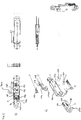
- FIG. 1 The lower door leaf element 10 of a sectional door is shown, on which a securing device 100 is attached, which is coupled to a weight compensation device (not shown) via a pulling means 150 designed as a pulling rope.
- the safety device has a housing 120 (cf. Fig. 2 ) arranged securing element 110 and an actuating element 130 at least partially accommodated in the housing 120.
- the securing element 110 is pivotably mounted in the housing with respect to a pivot axis 112 extending perpendicular to the direction of movement of the door leaf and approximately parallel to the joint axes of the individual door leaf elements, and has a starting point from the pivot axis in FIG Fig. 1a ) shown closing position downwardly extending securing area 111.
- the securing element 110 is secured with the aid of a pretensioning device 119 (cf. Fig. 2a ) in the in Fig. 1a ) shown release position pushed.
- the actuating element 130 which is at least partially accommodated in the housing 120, is subjected to the tensile force of the weight balancing device exerted thereon by the traction means 150 in FIG Fig. 1a shown release position held. As soon as the tensile force exerted on the actuating element 130 via the traction means 150 diminishes, the actuating element 130 moves under the influence of a pretensioning device in the form of compression springs 132 (cf. Fig. 2 ) in the in Fig. 1a direction arrow P1 into the housing 120.
- a contact area 134 of the actuating element 130 comes into contact with an actuating area 110a of the securing element 110.
- the actuating area 110a is arranged on a side of the pivot axis 112 facing away from a securing area 111 of the securing element 110.
- the contact area 134 of the actuating element 130 abutting the actuating area 110a forces the actuating area 110a downward under the action of the biasing force of the biasing device 132 and thus pivots the securing area 111 of the securing element 110 upward, so that the securing area 111 passes through a window in the housing 120 and in the in the 1b) and 1c ) safety position shown arrives.
- a tapered lower end 118 of the securing area 111 engages in a bulge 210 open at the top on a side frame spar of the door and thus counteracts a closing movement in cooperation with the bulge 210.
- the securing element 110 pivoted into the securing position, can cooperate with bulges 220 of the side frame spar that are open at the bottom and counteract an opening movement of the door leaf.
- the securing area 111 is in the area of its when pivoting from the in Fig. 1a ) shown release position in the in the Figures 1b) and 1c ) shown securing position leading edge equipped with an indentation 116, in which an edge of the bulge 220 can engage, so as to counteract the opening movement.
- Fig. 2a is the security facility of the in Fig. 1 shown gate exploded.
- Fig. 2b this safety device is shown in the assembled state.
- the securing element 110 in the in Fig. 2b ) shown release position arranged within the housing 120 and rotatably mounted within the housing 120 on a bolt 122.
- the bolt 122 passes through recesses 123 in opposite housing walls.
- the securing element 110 is Fig. 2b ) shown release position pushed.
- the actuating element 130 engages over compression springs 132 of the securing device, which bear against an abutment 126 arranged within the housing 120.
- the abutment 126 is generally approximately U-shaped, with the outer legs of the abutment being penetrated by a recess which is penetrated by a bolt 124.
- the bolt 124 also extends through recess 125 in the opposite walls of the housing 120.
- the connecting leg of the abutment forms a contact surface for the compression springs 132.
- elongated holes 136 are made, which are also penetrated by the bolt 124.
- a connecting leg 138 of the fork-shaped actuating element 130 provides a contact surface for the compression springs which, on the other hand, bear against the connecting leg of the U-shaped abutment 124. With the help of these compression springs, the fork-shaped actuating element is urged with respect to the abutment 126 in the direction of the securing element 110. On the other hand, the actuating element can be pulled out of the housing against the pretensioning force of the compression springs 132 by means of a pulling force which can be exerted thereon by means of a pulling means 150, this movement being limited by the elongated holes 136.
- the contact area 134 of the actuating element 130 comes into contact with the actuating area 110a of the securing element 110 and urges the securing element 110 as a whole through pivoting with respect to the pivot axis defined by the bolt 122 through a window of the housing into the Figures 1c and 1b shown securing position, in which it cooperates on the one hand with the aid of the recess 116 provided in the leading edge can counteract an opening movement with abutments 220 and, on the other hand, cooperate with the abutments 210 to counteract a closing movement.
- the securing element of the securing device according to the invention is therefore essentially characterized in that it carries out two securing functions, one of which is brought about by the tapering lower end of the securing element and the other by the edge provided in the edge which leads from the release position to the securing during a movement Indentation 116 is produced.
- the shifting of the securing element 110 from the release position into the securing position is essentially independent of the direction of the force exerted on the securing device via the traction means, because actuation of the securing element becomes effective only by the force of the compression spring 132 acting parallel to the housing axis. This is achieved by imparting the force of the traction means to the securing element via the actuating element 130 guided in the housing 120.
- a securing bolt 300 serves as a transport lock and can be pulled out of the housing 120 after assembly.
- the actuating element 130 can then be operated under the action of the compression springs 132 from the in FIG Fig. 2b ) rest position shown in the operating position.
- the invention is not limited to the exemplary embodiment explained with the aid of the drawing, but is also intended for the use of safety devices in which the movement of the actuating element is guided with a rail-like guide.
- an indentation in the leading edge of the securing element an indentation can also be provided, which can interact with correspondingly designed abutments in the frame spar.
- an indentation can be provided at the lower end of the securing element be, which in turn can interact with correspondingly designed abutments in the side frame spar.
- two, three or more abutments designed in the form of bulges can be embodied in the frame spar interacting with the securing element both in the first section of the predetermined track and in the second section of the predetermined track.
Landscapes
- Engineering & Computer Science (AREA)
- Mechanical Engineering (AREA)
- Civil Engineering (AREA)
- Structural Engineering (AREA)
- Power-Operated Mechanisms For Wings (AREA)
- Closing And Opening Devices For Wings, And Checks For Wings (AREA)
Abstract
Description
- Die Erfindung betrifft ein Tor mit einem zwischen einer Schließstellung, in der es eine Wandöffnung verschließt, und einer Öffnungsstellung, in der es die Wandöffnung freigibt, bewegbaren und eine Mehrzahl von in Torblattbewegungsrichtung hintereinander angeordneten und bezüglich etwa senkrecht zur Torblattbewegungsrichtung verlaufenden Gelenkachsen gelenkig miteinander verbundenen Torblattelementen aufweisenden Torblatt und einer zwischen einer Freigabestellung, in der sie die Torblattbewegung freigibt und einer Sicherungsstellung, in der sie der Torblattbewegung zumindest längs eines ersten Abschnitts der Bewegungsbahn des Torblatts von der Öffnungsstellung in die Schließstellung und längs eines vorzugsweise die Schließstellung enthaltenden zweiten Abschnitts der Bewegungsbahn von der Schließstellung in die Öffnungsstellung entgegenwirkt, verstellbaren Sicherungseinrichtung mit einem bezüglich dem bei einer Schließbewegung vorlaufenden Torblattelement bewegbar gelagerten und zwischen einer Freigabestellung und einer Sicherungsstellung bewegbaren Sicherungselement, wobei das in die Sicherungsstellung bewegte Sicherungselement in dem ersten Abschnitt der Bewegungsbahn der Schließbewegung entgegenwirkt und in dem zweiten Abschnitt der Bewegungsbahn der Öffnungsbewegung entgegenwirkt.
- Bei derartigen, auch als Sektionaltore bezeichneten Toren ist das Torblatt in der Schließstellung üblicherweise etwa in einer Vertikalebene und in der Öffnungsstellung über Kopf vorzugsweise etwa in einer Horizontalebene angeordnet. Bei einer Öffnungsbewegung muss das Torblatt also angehoben werden. Zur Unterstützung der Öffnungsbewegung wird üblicherweise eine an das Torblatt gekoppelte Gewichtsausgleichseinrichtung eingesetzt, mit der eine das Torblatt in die Öffnungsstellung drängende Kraft auf das Torblatt ausgeübt werden kann. Solche Gewichtsausgleichseinrichtungen können beispielsweise in Form von Torsionsfedern verwirklicht sein, welche oberhalb der mit dem Torblatt zu verschließenden Öffnung und/oder am der Torblattöffnung abgewandten hinteren Ende der üblicherweise durch eine Führungsschienenanordnung vorgegebenen Bewegungsbahn des Torblatts angeordnet sein können und im Verlauf der Schließbewegung unter Aufnahme potentieller Energie des Torblatts gespannt werden. Zur Übertragung der Kraft von der Gewichtsausgleichseinrichtung auf das Torblatt und umgekehrt kann ein Zugmittel in Form einer Kette und/oder eines Zugseils eingesetzt werden.
- Bei derartigen Anordnungen muss sichergestellt werden, dass das Torblatt im Verlauf einer Schließbewegung nicht abstürzt, wenn das Zugmittel reißt und/oder die Gewichtsausgleichseinrichtung beispielsweise durch einen Federbruch anderweitig beschädigt wird. Darüber hinaus wird in vielen Fällen verlangt, dass auch eine Öffnungsbewegung durch Aufhebeln des in die Schließstellung gestellten Torblatts verhindert wird.
- Sowohl bei einer Beschädigung der Gewichtsausgleichseinrichtung als auch bei dem Versuch, das in die Schließstellung bewegte Torblatt aufzuhebeln, reduziert sich die über das Zugmittel von der Gewichtsausgleichseinrichtung auf das Torblatt übertragene Kraft. Dieser Umstand wird bei Toren der eingangs genannten Art, wie sie in der
EP 1 373 668 B1 beschrieben sind, ausgenutzt, um sowohl einen Absturz des Torblatts bei Beschädigung der Gewichtsausgleichseinrichtung als auch ein unerwünschtes Aufhebeln des Torblatts zu verhindert. - Dazu ist das Zugmittel der bekannten Tore an ein Sicherungselement der Sicherungseinrichtung gekoppelt, das sich in der Freigabestellung ausgehend von einer bezüglich dem unteren Torblattelement festgelegten Schwenkachse nach oben erstreckt. Das Zugmittel hält das Sicherungselement in dieser Freigabestellung. Wenn die von dem Zugmittel auf das Sicherungselement ausgeübte Zugkraft nachlässt, wird das Sicherungselement mit Hilfe einer Vorspanneinrichtung bezüglich der Schwenkachse in die Sicherungsstellung verschwenkt, in der es zusammenwirkend mit an seitlichen Zargenholmen des Tors vorgesehenen Widerlagern längs eines ersten Abschnitts der vorgegebenen Bahn der Schließbewegung entgegenwirkt und längs eines die Schließstellung enthaltenden zweiten Abschnitts der vorgegebenen Bahn einer Öffnungsbewegung entgegenwirkt.
- Bei den bekannten Toren sind die Widerlager im Bereich des ersten Abschnitts der vorgegebenen Bahn in Form von oben offenen Ausbuchtungen des seitlichen Zargenholms ausgeführt, während die Widerlager im Bereich des zweiten Abschnitts der vorgegebenen Bahn in Form von unten offenen Ausbuchtungen des seitlichen Zargenholms ausgeführt sind. Das in die Sicherungsstellung überführte Sicherungselement der bekannten Tore weist eine nach unten ragende Sperrklinke auf, die in der Sicherungsstellung in die nach oben offenen Ausbuchtungen des Zargenholms eingreifen kann. Ferner weist das Sicherungselement eine nach oben ragende Sperrldinke auf, welche im Bereich des zweiten Abschnitts der Bewegungsbahn in die nach unten offenen Ausbuchtungen des Zargenholms eingreifen kann, wenn das Sicherungselement in der Sicherungsstellung angeordnet ist.
- Beim Einsatz der bekannten Tore hat es sich allerdings gezeigt, dass es zu Fehlfunktionen kommen kann, bei denen die Sicherungseinrichtung die gewünschte Sicherungswirkung auch ohne Beschädigung der Gewichtsausgleichseinrichtung oder ohne einen Versuch, das Tor aufzuhebeln, hervorbringt. Dann wird die Schließ- und/oder Öffnungsbewegung unerwünscht blockiert.
- Angesichts dieser Probleme im Stand der Technik liegt der Erfindung die Aufgabe zugrunde, ein Tor mit einer Sicherungseinrichtung bereitzustellen, bei der die gewünschte Sicherungswirkung zuverlässig nur in den gewünschten Situationen hervorgebracht wird.
- Erfindungsgemäß wird diese Aufgabe durch eine Weiterbildung der bekannten Tore gelöst, die im Wesentlichen dadurch gekennzeichnet ist, dass die Sicherungseinrichtung ein zum Bewegen des Sicherungselements von der Freigabestellung in die Sicherungsstellung betätigbares und an ein Zugmittel gekoppeltes Betätigungselement aufweist, wobei das Zugmittel andererseits an eine die Öffnungsbewegung unterstützende Gewichtsausgleichseinrichtung gekoppelt ist.
- Diese Erfindung geht auf die Erkenntnis zurück, dass die bei den bekannten Toren beobachteten Probleme in erster Linie darauf zurückzuführen sind, dass die Schwenkstellung des Sicherungselements bezüglich der Schwenkachse nicht nur von dem Betrag der von dem Zugmittel auf das Sicherungselement ausgeübten Zugkraft, sondern auch von der Richtung dieser Zugkraft abhängt. Bei einer fehlerhaften Montage oder bei einer betriebsbedingten Verlagerung des Zugmittels kann es daher bei diesen Toren dazu kommen, dass das Sicherungselement auch ohne Beschädigung der Gewichtsausgleichseinrichtung oder ohne anderweitige Entlastung des Zugmittels in die Sicherungsstellung gelangt und so unerwünscht die Torblattbewegung blockiert.
- Bei erfindungsgemäßen Toren wird dieser Mangel dadurch beseitigt, dass das Zugmittel nicht unmittelbar an das Sicherungselement, sondern nur mittelbar über ein Betätigungselement an das Sicherungselement koppelbar ist. Auf diese Weise kann die Wirkung der Sicherungseinrichtung von der Richtung der auf die Sicherungseinrichtung ausgeübten Zugkraft des Zugmittels entkoppelt werden, um so eine unerwünschte Verlagerung des Sicherungselements in die Sicherungsstellung zu vermeiden.
- In diesem Zusammenhang hat es sich als besonders günstig erwiesen, wenn das Betätigungselement bezüglich dem unteren Torblattelement vorzugsweise in einer parallel zur Bewegungsrichtung des Torblatts verlaufenden Richtung verschiebbar ist und eine bezüglich dem unteren Torblattelement festgelegte Führungseinrichtung zum Führen und Begrenzen der Verschiebung des Betätigungselements vorgesehen ist. Auf diese Weise kann die Entkopplung der Verlagerung des Sicherungselements von der Richtung der Zugkraft des Zugmittels besonders zuverlässig erreicht werden, weil die Bewegungsrichtung des Betätigungselements durch die Führungseinrichtung vorgegeben ist und durch Änderung der Richtung der Zugkraft nicht beeinflusst werden kann.
- Im Rahmen der Erfindung hat es sich als besonders vorteilhaft erwiesen, wenn die Führungseinrichtung ein das Betätigungselement zumindest teilweise aufnehmendes Gehäuse aufweist. Mit Hilfe eines Gehäuses kann die Bewegung des Betätigungselements besonders zuverlässig linear geführt werden, wenn das Gehäuse das Betätigungselement in einer senkrecht zur Bewegungsrichtung des Betätigungselements verlaufenden Ebene vorzugsweise vollständig umschließt. Dabei kann ein zum Ankoppeln des Zugmittels an das Betätigungselement dienender Ankopplungsbereich des Betätigungselements in jeder Betriebsstellung außerhalb des Gehäuses angeordnet sein.
- Im Sinne einer zuverlässigen Auslösung der Sicherungswirkung des Sicherungselements hat es sich als besonders zweckmäßig erwiesen, wenn eine vorzugsweise zumindest teilweise in dem Gehäuse aufgenommene und das Betätigungselement in eine Betätigungsstellung, in der es das Sicherungselement in die Sicherungsstellung bewegt, drängende erste Vorspanneinrichtung vorgesehen ist. Dabei wird das Betätigungselement zweckmäßigerweise durch Zug an dem Zugmittel gegen die Vorspannkraft der ersten Vorspanneinrichtung in eine Ruhestellung gedrängt, in der es keine Bewegung des Sicherungselements in die Sicherungsstellung bewirkt.
- Eine unbeabsichtigte Auslösung der Sicherungseinrichtung kann zuverlässig verhindert werden, wenn eine zweite Vorspanneinrichtung vorgesehen ist, mit der das Sicherungselement in die Freigabestellung gedrängt wird. Dann wird die Sicherungswirkung nur ausgelöst, wenn das Sicherungselement gegen die Vorspannkraft der zweiten Vorspanneinrichtung mit Hilfe des Betätigungselements in die Sicherungsstellung gedrängt wird.
- Zweckmäßigerweise ist die erste Vorspanneinrichtung so ausgelegt, dass das Betätigungselement mit der ersten Vorspanneinrichtung in das Gehäuse gedrängt wird. Zu diesem Zweck kann die Vorspanneinrichtung eine Druckfeder aufweisen, die sich einerseits an einem in dem Gehäuse angeordneten Widerlager abstützt und andererseits das Betätigungselement beaufschlagt.
- Im Rahmen der Erfindung hat es sich zur Sicherung der Betriebszuverlässigkeit der Sicherungseinrichtung als besonders zweckmäßig erwiesen, wenn das Sicherungselement in dem Gehäuse bezüglich einer quer, insbesondere etwa senkrecht zur Bewegungsbahn und vorzugsweise etwa parallel zu den Gelenkachsen verlaufenden Schwenkachse verschwenkbar gelagert ist und sich ein Sicherungsbereich des Sicherungselements ausgehend von der Schwenkachse zumindest in der Freigabestellung nach unten erstreckt, wobei der Sicherungsbereich bei einer Bewegung von der Freigabestellung in die Sicherungsstellung nach oben verschwenkt wird. Die Verlagerung des Sicherungselements von der Freigabestellung in die Sicherungsstellung kann bei dieser Ausführungsform ermöglicht werden, wenn das Gehäuse ein Fenster aufweist, durch das das in der Freigabestellung zumindest teilweise in dem Gehäuse aufgenommene Sicherungselement zumindest mit seinem Sicherungsbereich hindurchtreten kann, wenn es in die Sicherungsstellung verlagert wird.
- Bei einer bevorzugten Ausführungsform der Erfindung weist ein bei einer Bewegung von der Freigabestellung in die Sicherungsstellung vorlaufender Rand des Sicherungsbereichs eine Einbuchtung auf, in die ein längs des zweiten Abschnitts der Bewegungsbahn feststehend angeordnetes Widerlager eingreifen kann, wenn der Sicherungsbereich in der Sicherungsstellung angeordnet ist. So kann einer unerwünschten Öffnungsbewegung des Torblatts entgegengewirkt werden. Das Widerlager kann ähnlich wie bei
EP 1 373 668 B1 in Form einer nach unten offenen Ausbuchtung in einem seitlichen Zargenholm ausgeführt sein, der an einer den mit dem Torblatt zu verschließenden Raum begrenzenden Wand befestigt sein kann. - Bei einer weiter bevorzugten Ausführungsform der Erfindung kann längs des ersten Abschnitts der Bewegungsbahn mindestens ein weiteres feststehend angeordnetes Widerlager vorgesehen sein, in das ein in der Freigabestellung unteres, vorzugsweise spitz zulaufendes Ende des Sicherungsbereichs eingreifen kann, wenn der Sicherungsbereich in der Sicherungsstellung angeordnet ist, um so ein Abstürzen des Torblatts bei Beschädigung des Zugmittels und/oder der Gewichtsausgleichseinrichtung zu verhindern. Ähnlich wie bei Toren gemäß
EP 1 373 688 B1 kann das im ersten Abschnitt der Bewegungsbahn vorgesehene Widerlager in Form einer oben offenen Ausbuchtung eines seitlichen Zargenholms ausgeführt sein. - Sowohl im ersten Abschnitt der vorgegebenen Bahn als auch im zweiten Abschnitt der vorgegebenen Bahn können zwei, drei oder mehr Widerlager vorgesehen sein, welche zusammenwirkend mit dem Sicherungselement der Sicherungseinrichtung einer Bewegung des Torblatts entgegenwirken können.
- Erfindungsgemäße Sektionaltore können ebenso wie herkömmliche Sektionaltore eine Führungsschienenanordnung zum Führen der Torblattbewegung mit einem ersten geradlinig verlaufenden Führungsschienenabschnitt, der sich etwa in Schwererichtung etwa parallel zum seitlichen Rand des Torblatts in der Schließstellung erstreckt, einem zweiten, etwa geradlinig verlaufenden Abschnitt, der sich etwa parallel zum seitlichen Rand des Torblatts in der Öffnungsstellung erstreckt und einem die beiden geradlinig verlaufenden Abschnitte miteinander verbindenden bogenförmigen Führungsschienenabschnitt aufweisen. Zur Führung der Torblattbewegung können an den einzelnen Torblattelementen und im Besonderen im Bereich des vorlaufenden unteren Rands des unteren Torblattelements mit der Führungsschienenanordnung zusammenwirkende Führungselemente angeordnet sein, die vorzugsweise in Form von Führungsrollen ausgeführt sind.
- Zur Vergrößerung der möglichen Durchfahrtshöhe bei geöffnetem Tor kann das im Bereich des bei einer Schließbewegung vorlaufenden unteren Rands des unteren Torblattelements angebrachte Führungselement über einen bezüglich einer etwa senkrecht zur Bewegungsbahn verlaufenden Schwenkachse verschwenkbaren Halter an dem Torblattelement angebracht sein. Derartige Tore sind beispielsweise in der
DE 10 2017 123 493 beschrieben. Insbesondere beim Betrieb solcher Tore hat sich der Einsatz von Sicherungseinrichtungen mit einem über ein Betätigungselement betätigten Sicherungselement als zweckmäßig erwiesen, weil so dem durch die verschwenkbare Lagerung der Führungsrolle eingeführten zusätzlichen Bewegungsfreiheitsgrad Rechnung getragen werden kann. - Eine zur Herstellung eines erfindungsgemäßen Tors ausgelegte erfindungsgemäße Sicherungseinrichtung weist ein Gehäuse auf, in dem ein Sicherungselement verschwenkbar gelagert ist, wobei in dem Gehäuse ein Fenster vorgesehen sein kann, durch das das Sicherungselement hindurchtreten kann. Die Sicherungseinrichtung umfasst ferner ein zumindest teilweise in dem Gehäuse aufgenommenes und von dem Gehäuse geführtes Betätigungselement auf, das ggf. mit Hilfe einer Vorspanneinrichtung in Form einer Druckfeder in das Gehäuse gedrückt wird, wo es in Anlage an das Sicherungselement gelangen kann und einen Sicherungsbereich des Sicherungselements unter der Wirkung der Vorspannkraft der Vorspanneinrichtung aus dem Gehäuse drängen kann. Ein außerhalb des Gehäuses freiliegender Bereich des Betätigungselements kann zum Ankoppeln eines andererseits an eine Gewichtsausgleichseinrichtung gekoppeltes Zugmittel ausgelegt sein.
- Nachstehend wird die Erfindung unter Bezugnahme auf die Zeichnung, auf die hinsichtlich aller erfindungswesentlichen und in der Beschreibung nicht näher herausgestellten Einzelheiten ausdrücldich Bezug genommen wird, erläutert. In der Zeichnung zeigt:
- Fig. 1
- Eine schematische Darstellung eines erfindungsgemäßen Tors und
- Fig. 2
- Eine schematische Darstellung der Sicherungseinrichtung des in
Fig. 1 dargestellten Tors. - In
Fig. 1 ist das untere Torblattelement 10 eines Sektionaltors dargestellt, an dem eine Sicherungseinrichtung 100 angebracht ist, die über ein als Zugseil 150 ausgeführtes Zugmittel an eine nicht dargestellte Gewichtsausgleichseinrichtung gekoppelt ist. Die Sicherungseinrichtung weist ein in einem Gehäuse 120 (vgl.Fig. 2 ) angeordnetes Sicherungselement 110 sowie ein zumindest teilweise in dem Gehäuse 120 aufgenommenes Betätigungselement 130 auf. Das Sicherungselement 110 ist bezüglich einer senkrecht zur Bewegungsrichtung des Torblatts und etwa parallel zu den Gelenkachsen der einzelne Torblattelemente miteinander verbindenden Gelenke verlaufenden Schwenkachse 112 verschwenkbar in dem Gehäuse gelagert und weist einen sich ausgehend von der Schwenkachse in der inFig. 1a ) dargestellten Schließstellung nach unten erstreckenden Sicherungsbereich 111 auf. - Das Sicherungselement 110 wird mit Hilfe einer Vorspanneinrichtung 119 (vgl.
Fig. 2a ) in die inFig. 1a ) dargestellte Freigabestellung gedrängt. Das zumindest teilweise in dem Gehäuse 120 aufgenommene Betätigungselement 130 wird mit der über das Zugmittel 150 darauf ausgeübten Zugkraft der Gewichtsausgleichseinrichtung in der inFig. 1a dargestellten Freigabestellung gehalten. Sobald die über das Zugmittel 150 auf das Betätigungselement 130 ausgeübte Zugkraft nachlässt, bewegt sich das Betätigungselement 130 unter dem Einfluss einer Vorspanneinrichtung in Form von Druckfedern 132 (vgl.Fig. 2 ) in der inFig. 1a mit dem Pfeil P1 bezeichneten Richtung in das Gehäuse 120 hinein. Im Verlauf dieser Bewegung gelangt ein Anlagebereich 134 des Betätigungselements 130 in Anlage an einen Betätigungsbereich 110a des Sicherungselements 110. Dabei ist der Betätigungsbereich 110a auf einer einem Sicherungsbereich 111 des Sicherungselements 110 abgewandten Seite der Schwenkachse 112 angeordnet. - Der an dem Betätigungsbereich 110a anliegende Anlagebereich 134 des Betätigungselements 130 drängt unter Wirkung der Vorspannkraft der Vorspanneinrichtung 132 den Betätigungsbereich 110a nach unten und verschwenkt so den Sicherungsbereich 111 des Sicherungselements 110 nach oben, so dass der Sicherungsbereich 111 durch ein Fenster in dem Gehäuse 120 hindurchtritt und in die in den
Fig. 1b) und 1c ) dargestellte Sicherungsstellung gelangt. - In dieser Sicherungsstellung kann gemäß
Fig. 1b ) ein spitz zulaufendes unteres Ende 118 des Sicherungsbereichs 111 in eine oben offene Ausbuchtung 210 an einem seitlichen Zargenholm des Tors eingreifen und so zusammenwirkend mit der Ausbuchtung 210 einer Schließbewegung entgegenwirken. Andererseits kann das in die Sicherungsstellung verschwenkte Sicherungselement 110 zusammenwirkend mit unten offenen Ausbuchtungen 220 des seitlichen Zargenholms einer Öffnungsbewegung des Torblatts entgegenwirken. Dazu ist der Sicherungsbereich 111 im Bereich seines bei einer Verschwenkung von der inFig. 1a ) dargestellten Freigabestellung in die in denFiguren 1b) und 1c ) dargestellte Sicherungsstellung vorlaufenden Rand mit einer Einbuchtung 116 ausgestattet, in die ein Rand der Ausbuchtung 220 eingreifen kann, um so der Öffnungsbewegung entgegenzuwirken. - In
Fig. 2a ) ist die Sicherungseinrichtung des inFig. 1 dargestellten Tors explosionsartig dargestellt. InFig. 2b ) ist diese Sicherungseinrichtung in montiertem Zustand dargestellt. Wie einer Zusammenschau derFig. 2a) und 2b ) zu entnehmen ist, ist das Sicherungselement 110 in der inFig. 2b ) dargestellten Freigabestellung innerhalb des Gehäuses 120 angeordnet und innerhalb des Gehäuses 120 auf einem Bolzen 122 drehbar gelagert. Der Bolzen 122 durchsetzt Ausnehmungen 123 in gegenüberliegenden Gehäusewänden. Mit Hilfe der in dem Gehäuse 120 angeordneten Vorspanneinrichtung 119 wird das Sicherungselement 110 in die inFig. 2b ) dargestellte Freigabestellung gedrängt. - Das Betätigungselement 130 übergreift Druckfedern 132 der Sicherungseinrichtung, welche an einem innerhalb des Gehäuses 120 angeordneten Widerlager 126 anliegen. Das Widerlager 126 ist insgesamt etwa U-förmig ausgeführt, wobei die äußeren Schenkel des Widerlagers von einer Ausnehmung durchsetzt sind, die von einem Bolzen 124 durchgriffen sind. Der Bolzen 124 durchgreift ferner Ausnehmung 125 in den einander gegenüberliegenden Wänden des Gehäuses 120. Der Verbindungsschenkel des Widerlagers bildet eine Anlagefläche für die Druckfedern 132. In dem gabelförmigen Betätigungselement 130 sind Langlöcher 136 ausgeführt, die ebenfalls von dem Bolzen 124 durchgriffen werden. Ein Verbindungsschenkel 138 des gabelförmigen Betätigungselements 130 bietet eine Anlagefläche für die andererseits an den Verbindungsschenkel des U-förmigen Widerlagers 124 anliegenden Druckfedern. Mit Hilfe dieser Druckfedern wird das gabelförmige Betätigungselement insgesamt bezüglich dem Widerlager 126 in Richtung auf das Sicherungselement 110 gedrängt. Andererseits kann das Betätigungselement mit Hilfe einer Zugkraft, die über ein Zugmittel 150 darauf ausgeübt werden kann, gegen die Vorspannkraft der Druckfedern 132 aus dem Gehäuse herausgezogen werden, wobei diese Bewegung durch die Langlöcher 136 begrenzt wird.
- Bei nachlassender Zugkraft des Zugmittels gelangt der Anlagebereich 134 des Betätigungselements 130 in Anlage an den Betätigungsbereich 110a des Sicherungselements 110 und drängt das Sicherungselement 110 insgesamt durch Verschwenken bezüglich der durch den Bolzen 122 festgelegten Schwenkachse durch ein Fenster des Gehäuses in die in den
Figuren 1c und 1b dargestellte Sicherungsstellung, in der es einerseits mit Hilfe der in dem vorlaufenden Rand vorgesehenen Einbuchtung 116 zusammenwirkend mit Widerlagern 220 einer Öffnungsbewegung entgegenwirken kann und andererseits zusammenwirkend mit der Widerlagern 210 einer Schließbewegung entgegenwirken kann. - Das Sicherungselement der erfindungsgemäßen Sicherungseinrichtung ist demnach im Wesentlichen dadurch gekennzeichnet, dass es zwei Sicherungsfunktionen ausübt, von denen eine durch das spitz zulaufende untere Ende des Sicherungselements hervorgebracht wird und das andere durch die in dem bei einer Bewegung von der Freigabestellung in die Sicherstellung vorlaufenden Rand vorgesehene Einbuchtung 116 hervorgebracht wird. Dabei ist die Verlagerung des Sicherungselements 110 von der Freigabestellung in die Sicherungsstellung im Wesentlichen unabhängig von der Richtung der über das Zugmittel auf die Sicherungseinrichtung ausgeübten Kraft, weil nur durch die parallel zur Gehäuseachse wirksame Kraft der Druckfeder 132 eine Betätigung des Sicherungselements wirksam wird. Das wird durch die Vermittlung der Kraft des Zugmittels auf das Sicherungselement über das in dem Gehäuse 120 geführte Betätigungselement 130 erreicht.
- Bei der in
Fig. 2b ) dargestellten Ausführungsform der Erfindung wird eine Bewegung des Betätigungselements in die Betätigungsstellung mit Hilfe eines Sicherungsbolzens 300 verhindert. Der Sicherungsbolzen 300 dient als Transportsicherung und kann nach der Montage aus dem Gehäuse 120 gezogen werden. Dann kann das Betätigungselement 130 unter der Wirkung der Druckfedern 132 aus der inFig. 2b ) dargestellten Ruhestellung in die Betätigungsstellung verlagert werden. - Die Erfindung ist nicht auf das anhand der Zeichnung erläuterte Ausführungsbeispiel beschränkt, vielmehr ist auch an den Einsatz von solchen Sicherungseinrichtungen gedacht, bei denen die Bewegung des Betätigungselements mit einer schienenartigen Führung geführt wird. Anstelle einer Einbuchtung in dem vorlaufenden Rand des Sicherungselements kann auch eine Ausbuchtung vorgesehen sein, welche mit entsprechend ausgebildeten Widerlagern in dem Zargenholm zusammenwirken kann. Andererseits kann am unteren Ende des Sicherungselements eine Einbuchtung vorgesehen sein, die wiederum mit entsprechend ausgeführten Widerlagern im seitlichen Zargenholm zusammenwirken kann.
- Wie in den
Figuren 1b und 1c dargestellt, können in dem mit dem Sicherungselement zusammenwirkenden Zargenholm sowohl im ersten Abschnitt der vorgegebenen Bahn als auch im zweiten Abschnitt der vorgegebenen Bahn zwei, drei oder mehr in Form von Ausbuchtungen ausgeführte Widerlager ausgeführt sein. -
- 10
- Torblattelement
- 100
- Sicherungseinrichtung
- 110
- Sicherungselement
- 110a
- Betätigungsbereich
- 111
- Sicherungsbereich
- 112
- Schwenkachse
- 116
- Einbuchtung
- 118
- Unteres Endes des Sicherungsbereichs
- 119
- Vorspanneinrichtung
- 120
- Gehäuse
- 122
- Bolzen
- 123
- Ausnehmung
- 124
- Bolzen
- 126
- Widerlager
- 130
- Betätigungselement
- 132
- Druckfeder
- 134
- Anlagebereich
- 136
- Langloch
- 138
- Verbindungsschenkel
- 150
- Zugseil
- 210
- Oben offene Ausbuchtung
- 220
- Unten offene Ausbuchtung
- 300
- Sicherungsbolzen
Claims (15)
- Tor mit einem zwischen einer Schließstellung, in der es eine Wandöffnung verschließt, und einer Öffnungsstellung, in der es die Wandöffnung freigibt, bewegbaren und eine Mehrzahl von in Torblattbewegungsrichtung hintereinander angeordneten und bezüglich etwa senkrecht zur Torblattbewegungsrichtung verlaufenden Gelenkachsen gelenkig miteinander verbundenen Torblattelementen aufweisenden Torblatt und einer zwischen einer Freigabestellung, in der sie die Torblattbewegung freigibt, und einer Sicherungsstellung, in der sie der Torblattbewegung zumindest längs eines ersten Abschnitts der Bewegungsbahn des Torblatts von der Öffnungsstellung in die Schließstellung und längs eines vorzugsweise die Schließstellung enthaltenden zweiten Abschnitts der Bewegungsbahn von der Schließstellung in die Öffnungsstellung entgegenwirkt, verstellbaren Sicherungseinrichtung mit einem bezüglich dem bei einer Schließbewegung vorlaufenden Torblattelement bewegbar gelagerten und zwischen einer Freigabestellung und einer Sicherungsstellung bewegbaren Sicherungselement, wobei das in die Sicherungsstellung bewegte Sicherungselement in dem ersten Abschnitt der Bewegungsbahn der Schließbewegung entgegenwirkt und in dem zweiten Abschnitt der Bewegungsbahn der Öffnungsbewegung entgegenwirkt, dadurch gekennzeichnet, dass die Sicherungseinrichtung ein zum Bewegen des Sicherungselements von der Freigabestellung in die Sicherungsstellung betätigbares und an ein Zugmittel gekoppeltes Betätigungselement aufweist, wobei das Zugmittel andererseits an eine die Öffnungsbewegung unterstützende Gewichtsausgleichseinrichtung gekoppelt ist.
- Tor nach Anspruch 1, dadurch gekennzeichnet, dass das Betätigungselement bezüglich dem unteren Torblattelement vorzugsweise in einer etwa parallel zur Bewegungsrichtung des Torblatts verlaufenden Richtung, insbesondere linear, verschiebbar ist.
- Tor nach Anspruch 2, gekennzeichnet durch eine bezüglich dem unteren Torblattelement festgelegte Führungseinrichtung zum Führen und Begrenzen der Verschiebung des Betätigungselements.
- Tor nach Anspruch 3, dadurch gekennzeichnet, dass die Führungseinrichtung ein das Betätigungselement zumindest teilweise aufnehmendes Gehäuse aufweist.
- Tor nach einem der vorhergehenden Ansprüche, gekennzeichnet durch eine vorzugsweise zumindest teilweise in dem Gehäuse aufgenommene und das Betätigungselements in eine Betätigungsstellung, in der es das Sicherungselement in die Sicherungsstellung bewegt, drängende erste Vorspanneinrichtung.
- Tor nach Anspruch 5, dadurch gekennzeichnet, dass das Betätigungselement durch Zug an dem Zugmittel gegen die Vorspannkraft der Vorspanneinrichtung in eine Ruhestellung gedrängt wird, in der es keine Bewegung des Sicherungselements in die Sicherungsstellung bewirkt.
- Tor nach Anspruch 6, gekennzeichnet durch eine zweite Vorspanneinrichtung, mit der das Sicherungselement in die Freigabestellung gedrängt wird.
- Tor nach einem der Ansprüche 4 bis 7, dadurch gekennzeichnet, dass das Betätigungselement mit der ersten Vorspanneinrichtung in das Gehäuse gedrängt wird.
- Tor nach einem der Ansprüche 4 bis 8, dadurch gekennzeichnet, dass das Sicherungselement in dem Gehäuse bezüglich einer quer, insbesondere senkrecht zur Bewegungsbahn verlaufenden Schwenkachse verschwenkbar gelagert ist und sich ein Sicherungsbereich des Sicherungselements ausgehend von der Schwenkachse nach unten erstreckt, wobei der Sicherungsbereich bei einer Bewegung von der Freigabestellung in die Sicherungsstellung nach oben verschwenkt wird.
- Tor nach Anspruch 9, dadurch gekennzeichnet, dass ein bei einer Bewegung von der Freigabestellung in die Sicherungsstellung vorlaufender Rand des Sicherungsbereichs eine Einbuchtung aufweist, in die ein längs des zweiten Abschnitts der Bewegungsbahn feststehend angeordnetes Widerlager eingreifen kann, wenn der Sicherungsbereich in der Sicherungsstellung angeordnet ist.
- Tor nach einem der vorhergehenden Ansprüche, dadurch gekennzeichnet, dass längs des ersten Abschnitts der Bewegungsbahn mindestens ein weiteres feststehend angeordnetes Widerlager vorgesehen ist, in das ein in der Freigabestellung unteres, vorzugsweise spitz zulaufendes Ende des Sicherungsbereichs eingreifen kann, wenn der Sicherungsbereich in der Sicherungsstellung angeordnet ist.
- Tor nach einem der vorhergehenden Ansprüche, gekennzeichnet durch eine Führungsschienenanordnung zur Führung der Torblattbewegung mit einem ersten geradlinig verlaufenden Führungsschienenabschnitt, der sich etwa in Schwererichtung und etwa parallel zum seitlichen Rand des Torblatts in der Schließstellung erstreckt, einem zweiten etwa geradlinig verlaufenden Abschnitt, der sich etwa parallel zum seitlichen Rand des Torblatts in der Öffnungsstellung erstreckt und einem die beiden geradlinig verlaufenden Abschnitte miteinander verbindenden bogenförmigen Führungsschienenabschnitt.
- Tor nach Anspruch 12, gekennzeichnet durch ein an dem unteren Torblattelement angebrachtes und mit der Führungsschienenanordnung zusammenwirkendes Führungselement, das vorzugsweise als Führungsrolle ausgeführt ist.
- Tor nach Anspruch 13, dadurch gekennzeichnet, dass das Führungselement über einen bezüglich einer etwa senkrecht zur Bewegungsbahn verlaufenden Schwenkachse verschwenkbaren Halter an dem unteren Torblattelement angebracht ist.
- Sicherungseinrichtung für ein Tor nach einem der vorhergehenden Ansprüche.
Priority Applications (1)
| Application Number | Priority Date | Filing Date | Title |
|---|---|---|---|
| PL19184632T PL3608493T3 (pl) | 2018-08-10 | 2019-07-05 | Brama wyposażona w urządzenie zabezpieczające |
Applications Claiming Priority (1)
| Application Number | Priority Date | Filing Date | Title |
|---|---|---|---|
| DE102018119495.1A DE102018119495A1 (de) | 2018-08-10 | 2018-08-10 | Tor mit Sicherungseinrichtung |
Publications (2)
| Publication Number | Publication Date |
|---|---|
| EP3608493A1 true EP3608493A1 (de) | 2020-02-12 |
| EP3608493B1 EP3608493B1 (de) | 2022-02-16 |
Family
ID=67184856
Family Applications (1)
| Application Number | Title | Priority Date | Filing Date |
|---|---|---|---|
| EP19184632.8A Active EP3608493B1 (de) | 2018-08-10 | 2019-07-05 | Tor mit sicherungseinrichtung |
Country Status (5)
| Country | Link |
|---|---|
| EP (1) | EP3608493B1 (de) |
| DE (1) | DE102018119495A1 (de) |
| EA (1) | EA039015B1 (de) |
| ES (1) | ES2748845T1 (de) |
| PL (1) | PL3608493T3 (de) |
Cited By (1)
| Publication number | Priority date | Publication date | Assignee | Title |
|---|---|---|---|---|
| EP4325011A1 (de) | 2022-08-16 | 2024-02-21 | Hörmann KG Brockhagen | Industrietor |
Families Citing this family (1)
| Publication number | Priority date | Publication date | Assignee | Title |
|---|---|---|---|---|
| WO2024080972A1 (en) * | 2022-10-11 | 2024-04-18 | Clopay Corporation | Door stop mechanism |
Citations (5)
| Publication number | Priority date | Publication date | Assignee | Title |
|---|---|---|---|---|
| WO1996005395A1 (de) * | 1994-08-08 | 1996-02-22 | Hörmann KG Brockhagen | Tor mit einem vertikal bewegbaren, an seilen gehaltenem torblatt |
| WO2003087506A1 (de) * | 2002-04-15 | 2003-10-23 | Hörmann KG Brockhagen | Tor mit sicherungseinrichtung |
| EP1373668A1 (de) | 2001-03-21 | 2004-01-02 | Hörmann KG Brockhagen | Sicherungsvorrichtung |
| EP1373688A1 (de) | 2001-02-17 | 2004-01-02 | Dr.Ing. h.c.F. Porsche Aktiengesellschaft | Brennkraftmaschine mit einem zylinderkurbelgehäuse |
| WO2007128120A1 (en) * | 2006-05-08 | 2007-11-15 | Canimex Inc. | Brake device with integrated anti-theft mechanism for garage doors and the like, and door assembly including the same |
Family Cites Families (6)
| Publication number | Priority date | Publication date | Assignee | Title |
|---|---|---|---|---|
| US2041372A (en) * | 1930-06-23 | 1936-05-19 | Kinnear Mfg Co | Door structure |
| US5222541A (en) * | 1992-07-22 | 1993-06-29 | Kelley Company, Inc. | Industrial door having releasable beam and tension bracket retention mechanism |
| DE29808661U1 (de) * | 1998-05-15 | 1999-09-23 | Antriebstechnik Dr Ing Guenthe | Sicherungsvorrichtung für mittels Tragseil hebbare Tore |
| DK1743079T3 (da) * | 2004-05-06 | 2009-03-30 | Hoermann Kg | Port med sikringsindretning |
| DE102006011305B4 (de) * | 2006-03-11 | 2009-12-10 | Novoferm Nederland B.V. | Tor, insbesondere Sektionaltor |
| RU150217U1 (ru) * | 2014-08-15 | 2015-02-10 | Александр Владимирович КРОТОВ | Огнестойкая торцевая роликовая дверь |
-
2018
- 2018-08-10 DE DE102018119495.1A patent/DE102018119495A1/de active Pending
-
2019
- 2019-07-05 ES ES19184632T patent/ES2748845T1/es active Pending
- 2019-07-05 PL PL19184632T patent/PL3608493T3/pl unknown
- 2019-07-05 EP EP19184632.8A patent/EP3608493B1/de active Active
- 2019-08-01 EA EA201991639A patent/EA039015B1/ru unknown
Patent Citations (5)
| Publication number | Priority date | Publication date | Assignee | Title |
|---|---|---|---|---|
| WO1996005395A1 (de) * | 1994-08-08 | 1996-02-22 | Hörmann KG Brockhagen | Tor mit einem vertikal bewegbaren, an seilen gehaltenem torblatt |
| EP1373688A1 (de) | 2001-02-17 | 2004-01-02 | Dr.Ing. h.c.F. Porsche Aktiengesellschaft | Brennkraftmaschine mit einem zylinderkurbelgehäuse |
| EP1373668A1 (de) | 2001-03-21 | 2004-01-02 | Hörmann KG Brockhagen | Sicherungsvorrichtung |
| WO2003087506A1 (de) * | 2002-04-15 | 2003-10-23 | Hörmann KG Brockhagen | Tor mit sicherungseinrichtung |
| WO2007128120A1 (en) * | 2006-05-08 | 2007-11-15 | Canimex Inc. | Brake device with integrated anti-theft mechanism for garage doors and the like, and door assembly including the same |
Cited By (2)
| Publication number | Priority date | Publication date | Assignee | Title |
|---|---|---|---|---|
| EP4325011A1 (de) | 2022-08-16 | 2024-02-21 | Hörmann KG Brockhagen | Industrietor |
| DE102022120651A1 (de) | 2022-08-16 | 2024-02-22 | Hörmann KG Brockhagen | Industrietor |
Also Published As
| Publication number | Publication date |
|---|---|
| PL3608493T3 (pl) | 2022-06-06 |
| EA039015B1 (ru) | 2021-11-22 |
| EP3608493B1 (de) | 2022-02-16 |
| EA201991639A1 (ru) | 2020-02-28 |
| DE102018119495A1 (de) | 2020-02-13 |
| ES2748845T1 (es) | 2020-03-18 |
Similar Documents
| Publication | Publication Date | Title |
|---|---|---|
| EP0040800B1 (de) | Rolladen | |
| EP3608493B1 (de) | Tor mit sicherungseinrichtung | |
| EP1373668B1 (de) | Sicherungsvorrichtung | |
| EP1495203B1 (de) | Tor mit sicherungseinrichtung | |
| EP0678639B1 (de) | Verriegelung für Schiebeläden, Schiebetüren und dgl. entlang einer feststehenden Schiene verfahrbare Elemente | |
| EP3695081B1 (de) | Tor mit einem unteren torglied mit klapprollenhalter | |
| EP3789572B1 (de) | Fahrzeugaufbau | |
| EP1366259B1 (de) | Sektionaltor | |
| DE2527880A1 (de) | Vorrichtung zur sicherung von rollaeden | |
| EP4087997A1 (de) | Torvorrichtung und abstellvorrichtung hiermit | |
| WO1995024541A1 (de) | Absturzsicherung | |
| DE102019123727B4 (de) | Fahrzeugaufbau | |
| DE10228156B4 (de) | Notentriegelung mit Verriegelung | |
| DE102012210584A1 (de) | Schiebetüranlage | |
| EP1743079B1 (de) | Tor mit sicherungseinrichtung | |
| DE102007033412A1 (de) | Rolltor | |
| DE102004063924B4 (de) | Hubtor | |
| EP1414689A1 (de) | Bewegliche verriegelung für schiebewände | |
| EP1497522B1 (de) | Sektionaltor und führungsanordnung dafür | |
| DE202021102462U1 (de) | Torsystem | |
| DE102006039570B4 (de) | Nothandkettenentriegelung | |
| WO2004099542A1 (de) | Sektionaltor | |
| DE102004014350A1 (de) | Hubtor | |
| DE10348543A1 (de) | Hubtor | |
| DE2245836A1 (de) | Deckentor mit antriebsvorrichtungen |
Legal Events
| Date | Code | Title | Description |
|---|---|---|---|
| PUAI | Public reference made under article 153(3) epc to a published international application that has entered the european phase |
Free format text: ORIGINAL CODE: 0009012 |
|
| STAA | Information on the status of an ep patent application or granted ep patent |
Free format text: STATUS: REQUEST FOR EXAMINATION WAS MADE |
|
| 17P | Request for examination filed |
Effective date: 20190705 |
|
| AK | Designated contracting states |
Kind code of ref document: A1 Designated state(s): AL AT BE BG CH CY CZ DE DK EE ES FI FR GB GR HR HU IE IS IT LI LT LU LV MC MK MT NL NO PL PT RO RS SE SI SK SM TR |
|
| AX | Request for extension of the european patent |
Extension state: BA ME |
|
| REG | Reference to a national code |
Ref country code: ES Ref legal event code: BA2A Ref document number: 2748845 Country of ref document: ES Kind code of ref document: T1 Effective date: 20200318 |
|
| REG | Reference to a national code |
Ref country code: SE Ref legal event code: TRCL |
|
| STAA | Information on the status of an ep patent application or granted ep patent |
Free format text: STATUS: EXAMINATION IS IN PROGRESS |
|
| 17Q | First examination report despatched |
Effective date: 20210201 |
|
| GRAP | Despatch of communication of intention to grant a patent |
Free format text: ORIGINAL CODE: EPIDOSNIGR1 |
|
| STAA | Information on the status of an ep patent application or granted ep patent |
Free format text: STATUS: GRANT OF PATENT IS INTENDED |
|
| INTG | Intention to grant announced |
Effective date: 20210923 |
|
| GRAS | Grant fee paid |
Free format text: ORIGINAL CODE: EPIDOSNIGR3 |
|
| GRAA | (expected) grant |
Free format text: ORIGINAL CODE: 0009210 |
|
| STAA | Information on the status of an ep patent application or granted ep patent |
Free format text: STATUS: THE PATENT HAS BEEN GRANTED |
|
| AK | Designated contracting states |
Kind code of ref document: B1 Designated state(s): AL AT BE BG CH CY CZ DE DK EE ES FI FR GB GR HR HU IE IS IT LI LT LU LV MC MK MT NL NO PL PT RO RS SE SI SK SM TR |
|
| REG | Reference to a national code |
Ref country code: GB Ref legal event code: FG4D Free format text: NOT ENGLISH |
|
| REG | Reference to a national code |
Ref country code: CH Ref legal event code: EP |
|
| REG | Reference to a national code |
Ref country code: DE Ref legal event code: R096 Ref document number: 502019003427 Country of ref document: DE |
|
| REG | Reference to a national code |
Ref country code: AT Ref legal event code: REF Ref document number: 1468982 Country of ref document: AT Kind code of ref document: T Effective date: 20220315 |
|
| REG | Reference to a national code |
Ref country code: IE Ref legal event code: FG4D Free format text: LANGUAGE OF EP DOCUMENT: GERMAN Ref country code: NL Ref legal event code: FP |
|
| REG | Reference to a national code |
Ref country code: SE Ref legal event code: TRGR |
|
| REG | Reference to a national code |
Ref country code: LT Ref legal event code: MG9D |
|
| PG25 | Lapsed in a contracting state [announced via postgrant information from national office to epo] |
Ref country code: RS Free format text: LAPSE BECAUSE OF FAILURE TO SUBMIT A TRANSLATION OF THE DESCRIPTION OR TO PAY THE FEE WITHIN THE PRESCRIBED TIME-LIMIT Effective date: 20220216 Ref country code: PT Free format text: LAPSE BECAUSE OF FAILURE TO SUBMIT A TRANSLATION OF THE DESCRIPTION OR TO PAY THE FEE WITHIN THE PRESCRIBED TIME-LIMIT Effective date: 20220616 Ref country code: NO Free format text: LAPSE BECAUSE OF FAILURE TO SUBMIT A TRANSLATION OF THE DESCRIPTION OR TO PAY THE FEE WITHIN THE PRESCRIBED TIME-LIMIT Effective date: 20220516 Ref country code: LT Free format text: LAPSE BECAUSE OF FAILURE TO SUBMIT A TRANSLATION OF THE DESCRIPTION OR TO PAY THE FEE WITHIN THE PRESCRIBED TIME-LIMIT Effective date: 20220216 Ref country code: HR Free format text: LAPSE BECAUSE OF FAILURE TO SUBMIT A TRANSLATION OF THE DESCRIPTION OR TO PAY THE FEE WITHIN THE PRESCRIBED TIME-LIMIT Effective date: 20220216 Ref country code: ES Free format text: LAPSE BECAUSE OF FAILURE TO SUBMIT A TRANSLATION OF THE DESCRIPTION OR TO PAY THE FEE WITHIN THE PRESCRIBED TIME-LIMIT Effective date: 20220216 Ref country code: BG Free format text: LAPSE BECAUSE OF FAILURE TO SUBMIT A TRANSLATION OF THE DESCRIPTION OR TO PAY THE FEE WITHIN THE PRESCRIBED TIME-LIMIT Effective date: 20220516 |
|
| PG25 | Lapsed in a contracting state [announced via postgrant information from national office to epo] |
Ref country code: LV Free format text: LAPSE BECAUSE OF FAILURE TO SUBMIT A TRANSLATION OF THE DESCRIPTION OR TO PAY THE FEE WITHIN THE PRESCRIBED TIME-LIMIT Effective date: 20220216 Ref country code: GR Free format text: LAPSE BECAUSE OF FAILURE TO SUBMIT A TRANSLATION OF THE DESCRIPTION OR TO PAY THE FEE WITHIN THE PRESCRIBED TIME-LIMIT Effective date: 20220517 Ref country code: FI Free format text: LAPSE BECAUSE OF FAILURE TO SUBMIT A TRANSLATION OF THE DESCRIPTION OR TO PAY THE FEE WITHIN THE PRESCRIBED TIME-LIMIT Effective date: 20220216 |
|
| PG25 | Lapsed in a contracting state [announced via postgrant information from national office to epo] |
Ref country code: IS Free format text: LAPSE BECAUSE OF FAILURE TO SUBMIT A TRANSLATION OF THE DESCRIPTION OR TO PAY THE FEE WITHIN THE PRESCRIBED TIME-LIMIT Effective date: 20220617 |
|
| PG25 | Lapsed in a contracting state [announced via postgrant information from national office to epo] |
Ref country code: SM Free format text: LAPSE BECAUSE OF FAILURE TO SUBMIT A TRANSLATION OF THE DESCRIPTION OR TO PAY THE FEE WITHIN THE PRESCRIBED TIME-LIMIT Effective date: 20220216 Ref country code: SK Free format text: LAPSE BECAUSE OF FAILURE TO SUBMIT A TRANSLATION OF THE DESCRIPTION OR TO PAY THE FEE WITHIN THE PRESCRIBED TIME-LIMIT Effective date: 20220216 Ref country code: RO Free format text: LAPSE BECAUSE OF FAILURE TO SUBMIT A TRANSLATION OF THE DESCRIPTION OR TO PAY THE FEE WITHIN THE PRESCRIBED TIME-LIMIT Effective date: 20220216 Ref country code: EE Free format text: LAPSE BECAUSE OF FAILURE TO SUBMIT A TRANSLATION OF THE DESCRIPTION OR TO PAY THE FEE WITHIN THE PRESCRIBED TIME-LIMIT Effective date: 20220216 Ref country code: DK Free format text: LAPSE BECAUSE OF FAILURE TO SUBMIT A TRANSLATION OF THE DESCRIPTION OR TO PAY THE FEE WITHIN THE PRESCRIBED TIME-LIMIT Effective date: 20220216 |
|
| PGFP | Annual fee paid to national office [announced via postgrant information from national office to epo] |
Ref country code: IT Payment date: 20220801 Year of fee payment: 4 |
|
| REG | Reference to a national code |
Ref country code: DE Ref legal event code: R097 Ref document number: 502019003427 Country of ref document: DE |
|
| PG25 | Lapsed in a contracting state [announced via postgrant information from national office to epo] |
Ref country code: AL Free format text: LAPSE BECAUSE OF FAILURE TO SUBMIT A TRANSLATION OF THE DESCRIPTION OR TO PAY THE FEE WITHIN THE PRESCRIBED TIME-LIMIT Effective date: 20220216 |
|
| PLBE | No opposition filed within time limit |
Free format text: ORIGINAL CODE: 0009261 |
|
| STAA | Information on the status of an ep patent application or granted ep patent |
Free format text: STATUS: NO OPPOSITION FILED WITHIN TIME LIMIT |
|
| 26N | No opposition filed |
Effective date: 20221117 |
|
| PG25 | Lapsed in a contracting state [announced via postgrant information from national office to epo] |
Ref country code: SI Free format text: LAPSE BECAUSE OF FAILURE TO SUBMIT A TRANSLATION OF THE DESCRIPTION OR TO PAY THE FEE WITHIN THE PRESCRIBED TIME-LIMIT Effective date: 20220216 Ref country code: MC Free format text: LAPSE BECAUSE OF FAILURE TO SUBMIT A TRANSLATION OF THE DESCRIPTION OR TO PAY THE FEE WITHIN THE PRESCRIBED TIME-LIMIT Effective date: 20220216 |
|
| REG | Reference to a national code |
Ref country code: CH Ref legal event code: PL |
|
| REG | Reference to a national code |
Ref country code: BE Ref legal event code: MM Effective date: 20220731 |
|
| PG25 | Lapsed in a contracting state [announced via postgrant information from national office to epo] |
Ref country code: LU Free format text: LAPSE BECAUSE OF NON-PAYMENT OF DUE FEES Effective date: 20220705 Ref country code: LI Free format text: LAPSE BECAUSE OF NON-PAYMENT OF DUE FEES Effective date: 20220731 Ref country code: FR Free format text: LAPSE BECAUSE OF NON-PAYMENT OF DUE FEES Effective date: 20220731 Ref country code: CH Free format text: LAPSE BECAUSE OF NON-PAYMENT OF DUE FEES Effective date: 20220731 |
|
| PG25 | Lapsed in a contracting state [announced via postgrant information from national office to epo] |
Ref country code: BE Free format text: LAPSE BECAUSE OF NON-PAYMENT OF DUE FEES Effective date: 20220731 |
|
| P01 | Opt-out of the competence of the unified patent court (upc) registered |
Effective date: 20230316 |
|
| PG25 | Lapsed in a contracting state [announced via postgrant information from national office to epo] |
Ref country code: IE Free format text: LAPSE BECAUSE OF NON-PAYMENT OF DUE FEES Effective date: 20220705 |
|
| PGFP | Annual fee paid to national office [announced via postgrant information from national office to epo] |
Ref country code: CZ Payment date: 20230623 Year of fee payment: 5 |
|
| PGFP | Annual fee paid to national office [announced via postgrant information from national office to epo] |
Ref country code: PL Payment date: 20230626 Year of fee payment: 5 Ref country code: NL Payment date: 20230720 Year of fee payment: 5 |
|
| PGFP | Annual fee paid to national office [announced via postgrant information from national office to epo] |
Ref country code: SE Payment date: 20230724 Year of fee payment: 5 Ref country code: DE Payment date: 20230720 Year of fee payment: 5 |
|
| GBPC | Gb: european patent ceased through non-payment of renewal fee |
Effective date: 20230705 |
|
| PG25 | Lapsed in a contracting state [announced via postgrant information from national office to epo] |
Ref country code: HU Free format text: LAPSE BECAUSE OF FAILURE TO SUBMIT A TRANSLATION OF THE DESCRIPTION OR TO PAY THE FEE WITHIN THE PRESCRIBED TIME-LIMIT; INVALID AB INITIO Effective date: 20190705 |
|
| PG25 | Lapsed in a contracting state [announced via postgrant information from national office to epo] |
Ref country code: MK Free format text: LAPSE BECAUSE OF FAILURE TO SUBMIT A TRANSLATION OF THE DESCRIPTION OR TO PAY THE FEE WITHIN THE PRESCRIBED TIME-LIMIT Effective date: 20220216 Ref country code: CY Free format text: LAPSE BECAUSE OF FAILURE TO SUBMIT A TRANSLATION OF THE DESCRIPTION OR TO PAY THE FEE WITHIN THE PRESCRIBED TIME-LIMIT Effective date: 20220216 Ref country code: GB Free format text: LAPSE BECAUSE OF NON-PAYMENT OF DUE FEES Effective date: 20230705 |