EP3607635B1 - Verfahren zum herstellen eines systems zur induktiven übertragung von energie an ein mobilteil und vorrichtung zur durchführung des verfahrens - Google Patents
Verfahren zum herstellen eines systems zur induktiven übertragung von energie an ein mobilteil und vorrichtung zur durchführung des verfahrens Download PDFInfo
- Publication number
- EP3607635B1 EP3607635B1 EP18712504.2A EP18712504A EP3607635B1 EP 3607635 B1 EP3607635 B1 EP 3607635B1 EP 18712504 A EP18712504 A EP 18712504A EP 3607635 B1 EP3607635 B1 EP 3607635B1
- Authority
- EP
- European Patent Office
- Prior art keywords
- floor
- stepped bore
- winding
- annular frame
- ist
- Prior art date
- Legal status (The legal status is an assumption and is not a legal conclusion. Google has not performed a legal analysis and makes no representation as to the accuracy of the status listed.)
- Active
Links
Images


Classifications
-
- H—ELECTRICITY
- H02—GENERATION; CONVERSION OR DISTRIBUTION OF ELECTRIC POWER
- H02J—ELECTRIC POWER NETWORKS; CIRCUIT ARRANGEMENTS OR SYSTEMS FOR SUPPLYING OR DISTRIBUTING ELECTRIC POWER; SYSTEMS FOR STORING ELECTRIC ENERGY
- H02J50/00—Circuit arrangements or systems for wireless supply or distribution of electric power
- H02J50/005—Mechanical details of housing or structure aiming to accommodate the power transfer means, e.g. mechanical integration of coils, antennas or transducers into emitting or receiving devices
-
- H—ELECTRICITY
- H02—GENERATION; CONVERSION OR DISTRIBUTION OF ELECTRIC POWER
- H02J—ELECTRIC POWER NETWORKS; CIRCUIT ARRANGEMENTS OR SYSTEMS FOR SUPPLYING OR DISTRIBUTING ELECTRIC POWER; SYSTEMS FOR STORING ELECTRIC ENERGY
- H02J50/00—Circuit arrangements or systems for wireless supply or distribution of electric power
- H02J50/10—Circuit arrangements or systems for wireless supply or distribution of electric power using inductive coupling
-
- B—PERFORMING OPERATIONS; TRANSPORTING
- B60—VEHICLES IN GENERAL
- B60L—PROPULSION OF ELECTRICALLY-PROPELLED VEHICLES; SUPPLYING ELECTRIC POWER FOR AUXILIARY EQUIPMENT OF ELECTRICALLY-PROPELLED VEHICLES; ELECTRODYNAMIC BRAKE SYSTEMS FOR VEHICLES IN GENERAL; MAGNETIC SUSPENSION OR LEVITATION FOR VEHICLES; MONITORING OPERATING VARIABLES OF ELECTRICALLY-PROPELLED VEHICLES; ELECTRIC SAFETY DEVICES FOR ELECTRICALLY-PROPELLED VEHICLES
- B60L53/00—Methods of charging batteries, specially adapted for electric vehicles; Charging stations or on-board charging equipment therefor; Exchange of energy storage elements in electric vehicles
- B60L53/10—Methods of charging batteries, specially adapted for electric vehicles; Charging stations or on-board charging equipment therefor; Exchange of energy storage elements in electric vehicles characterised by the energy transfer between the charging station and the vehicle
- B60L53/12—Inductive energy transfer
-
- B—PERFORMING OPERATIONS; TRANSPORTING
- B60—VEHICLES IN GENERAL
- B60L—PROPULSION OF ELECTRICALLY-PROPELLED VEHICLES; SUPPLYING ELECTRIC POWER FOR AUXILIARY EQUIPMENT OF ELECTRICALLY-PROPELLED VEHICLES; ELECTRODYNAMIC BRAKE SYSTEMS FOR VEHICLES IN GENERAL; MAGNETIC SUSPENSION OR LEVITATION FOR VEHICLES; MONITORING OPERATING VARIABLES OF ELECTRICALLY-PROPELLED VEHICLES; ELECTRIC SAFETY DEVICES FOR ELECTRICALLY-PROPELLED VEHICLES
- B60L53/00—Methods of charging batteries, specially adapted for electric vehicles; Charging stations or on-board charging equipment therefor; Exchange of energy storage elements in electric vehicles
- B60L53/30—Constructional details of charging stations
-
- H—ELECTRICITY
- H01—ELECTRIC ELEMENTS
- H01F—MAGNETS; INDUCTANCES; TRANSFORMERS; SELECTION OF MATERIALS FOR THEIR MAGNETIC PROPERTIES
- H01F27/00—Details of transformers or inductances, in general
- H01F27/02—Casings
-
- H—ELECTRICITY
- H01—ELECTRIC ELEMENTS
- H01F—MAGNETS; INDUCTANCES; TRANSFORMERS; SELECTION OF MATERIALS FOR THEIR MAGNETIC PROPERTIES
- H01F38/00—Adaptations of transformers or inductances for specific applications or functions
- H01F38/14—Inductive couplings
-
- H—ELECTRICITY
- H01—ELECTRIC ELEMENTS
- H01F—MAGNETS; INDUCTANCES; TRANSFORMERS; SELECTION OF MATERIALS FOR THEIR MAGNETIC PROPERTIES
- H01F41/00—Apparatus or processes specially adapted for manufacturing or assembling magnets, inductances or transformers; Apparatus or processes specially adapted for manufacturing materials characterised by their magnetic properties
-
- H—ELECTRICITY
- H02—GENERATION; CONVERSION OR DISTRIBUTION OF ELECTRIC POWER
- H02J—ELECTRIC POWER NETWORKS; CIRCUIT ARRANGEMENTS OR SYSTEMS FOR SUPPLYING OR DISTRIBUTING ELECTRIC POWER; SYSTEMS FOR STORING ELECTRIC ENERGY
- H02J50/00—Circuit arrangements or systems for wireless supply or distribution of electric power
- H02J50/10—Circuit arrangements or systems for wireless supply or distribution of electric power using inductive coupling
- H02J50/12—Circuit arrangements or systems for wireless supply or distribution of electric power using inductive coupling of the resonant type
-
- H—ELECTRICITY
- H02—GENERATION; CONVERSION OR DISTRIBUTION OF ELECTRIC POWER
- H02J—ELECTRIC POWER NETWORKS; CIRCUIT ARRANGEMENTS OR SYSTEMS FOR SUPPLYING OR DISTRIBUTING ELECTRIC POWER; SYSTEMS FOR STORING ELECTRIC ENERGY
- H02J50/00—Circuit arrangements or systems for wireless supply or distribution of electric power
- H02J50/90—Circuit arrangements or systems for wireless supply or distribution of electric power involving detection or optimisation of position, e.g. alignment
-
- Y—GENERAL TAGGING OF NEW TECHNOLOGICAL DEVELOPMENTS; GENERAL TAGGING OF CROSS-SECTIONAL TECHNOLOGIES SPANNING OVER SEVERAL SECTIONS OF THE IPC; TECHNICAL SUBJECTS COVERED BY FORMER USPC CROSS-REFERENCE ART COLLECTIONS [XRACs] AND DIGESTS
- Y02—TECHNOLOGIES OR APPLICATIONS FOR MITIGATION OR ADAPTATION AGAINST CLIMATE CHANGE
- Y02T—CLIMATE CHANGE MITIGATION TECHNOLOGIES RELATED TO TRANSPORTATION
- Y02T10/00—Road transport of goods or passengers
- Y02T10/60—Other road transportation technologies with climate change mitigation effect
- Y02T10/70—Energy storage systems for electromobility, e.g. batteries
-
- Y—GENERAL TAGGING OF NEW TECHNOLOGICAL DEVELOPMENTS; GENERAL TAGGING OF CROSS-SECTIONAL TECHNOLOGIES SPANNING OVER SEVERAL SECTIONS OF THE IPC; TECHNICAL SUBJECTS COVERED BY FORMER USPC CROSS-REFERENCE ART COLLECTIONS [XRACs] AND DIGESTS
- Y02—TECHNOLOGIES OR APPLICATIONS FOR MITIGATION OR ADAPTATION AGAINST CLIMATE CHANGE
- Y02T—CLIMATE CHANGE MITIGATION TECHNOLOGIES RELATED TO TRANSPORTATION
- Y02T10/00—Road transport of goods or passengers
- Y02T10/60—Other road transportation technologies with climate change mitigation effect
- Y02T10/7072—Electromobility specific charging systems or methods for batteries, ultracapacitors, supercapacitors or double-layer capacitors
-
- Y—GENERAL TAGGING OF NEW TECHNOLOGICAL DEVELOPMENTS; GENERAL TAGGING OF CROSS-SECTIONAL TECHNOLOGIES SPANNING OVER SEVERAL SECTIONS OF THE IPC; TECHNICAL SUBJECTS COVERED BY FORMER USPC CROSS-REFERENCE ART COLLECTIONS [XRACs] AND DIGESTS
- Y02—TECHNOLOGIES OR APPLICATIONS FOR MITIGATION OR ADAPTATION AGAINST CLIMATE CHANGE
- Y02T—CLIMATE CHANGE MITIGATION TECHNOLOGIES RELATED TO TRANSPORTATION
- Y02T90/00—Enabling technologies or technologies with a potential or indirect contribution to GHG emissions mitigation
- Y02T90/10—Technologies relating to charging of electric vehicles
- Y02T90/12—Electric charging stations
-
- Y—GENERAL TAGGING OF NEW TECHNOLOGICAL DEVELOPMENTS; GENERAL TAGGING OF CROSS-SECTIONAL TECHNOLOGIES SPANNING OVER SEVERAL SECTIONS OF THE IPC; TECHNICAL SUBJECTS COVERED BY FORMER USPC CROSS-REFERENCE ART COLLECTIONS [XRACs] AND DIGESTS
- Y02—TECHNOLOGIES OR APPLICATIONS FOR MITIGATION OR ADAPTATION AGAINST CLIMATE CHANGE
- Y02T—CLIMATE CHANGE MITIGATION TECHNOLOGIES RELATED TO TRANSPORTATION
- Y02T90/00—Enabling technologies or technologies with a potential or indirect contribution to GHG emissions mitigation
- Y02T90/10—Technologies relating to charging of electric vehicles
- Y02T90/14—Plug-in electric vehicles
Definitions
- the invention relates to a method for producing a system for the inductive transmission of energy to a handset.
- a transformer is known as the closest prior art, the primary part of which is stationary and the secondary part of which is rotatable.
- the invention is therefore based on the object of improving safety in a system for inductive charging.
- the advantage here is that the ring frame can be aligned on the surface of the floor, in particular on the exact height of the floor covering on the floor.
- the primary part can thus be easily connected to the ring frame and the occurrence of a tripping hazard is prevented. This accessibility reduces the risk of accidents and thus improves safety.
- the sealing body bears against the stepped bore, in particular on a region of the stepped bore arranged below the step of the stepped bore, in particular is pressed, and on the annular frame, in particular on the inner wall of the annular annular frame.
- the advantage here is that is prevented by means of the sealing body that potting compound in the for the primary part and / or for its Supply line provided spatial area of the stepped bore flows.
- the sealing body is made of an elastic plastic material, such as foam, and has a centrally arranged hole, or the sealing body is designed to be inflatable so that when inflated it rests against the lower area of the stepped bore and the inner wall of the ring frame.
- the gap area provided for the casting compound between the ring frame and the base is at least also delimited by the sealing body.
- the primary part has a winding in particular, an electrical supply line for the winding being arranged in an empty tube which opens into the area arranged below the step of the stepped bore.
- the supply line for supplying a medium-frequency alternating current can be arranged in a well-protected manner at the charging point, ie also at the primary part.
- the alignment unit is aligned on the surface of the floor covering of the floor.
- the advantage here is that alignment on the surface and thus on the floor level present on the floor covering is made possible.
- the ring frame is arranged above the step of the stepped bore.
- the advantage here is that the device is easy to manufacture and the primary part can be installed precisely, that is to say in particular that the installation height is precisely matched to the surface of the floor, in particular the floor covering.
- the winding in the primary part can be implemented as a circular spiral flat winding, i.e. without a preferred direction.
- This allows the handset to be charged while the handset is rotated over the charging point.
- the handset has an omnidirectional drive, so it can rotate on the spot.
- the axis of rotation is preferably aligned coaxially to the axis of the stepped bore.
- a lower part is connected to the receiving part on the side of the receiving part facing away from the cover part, wherein between the receiving part and the lower part a circumferential, in particular ring-shaped spatial area is formed in the circumferential direction, in which a printed circuit board equipped with at least one capacitor arrangement is arranged.
- the advantage here is that electrical compensation can be arranged in the spatial area.
- the lower part is screw-connected to the receiving part, wherein the cover part is screw-connected to the ring frame by means of screws passing through the receiving part.
- a further spatial region is formed between the receiving part and the lower part, spaced apart from the circumferential, in particular annular, spatial region, in particular arranged at a smaller radial distance from the central axis of the stepped bore.
- the capacitor arrangement is connected in series or in parallel with the winding and is dimensioned in such a way that the resonant frequency of the resonant circuit formed in this way essentially corresponds to the frequency of the resonant circuit or the Corresponds to the applied alternating current winding.
- the advantage here is that a high level of efficiency can be achieved.
- a cable gland is arranged on the underside of the lower part, to which the supply line is routed.
- the receiving part, the cover part and the lower part have a circular outer edge area and/or a maximum radial distance, which is independent of the circumferential angle.
- the advantage here is that the primary part can be accommodated in the annular frame, which is arranged in the stepped bore, which is designed as a round bore. Thus, manufacturing is easy.
- the winding has a preferred direction that is aligned parallel to the traversing plane of the handset, and/or the maximum radial distance of the winding has different values depending on the circumferential angle.
- An alternative design of the winding without a preferred direction i.e. as a circular flat winding aligned coaxially with the axis of the stepped bore, allows charging while the handset is rotating without the inductive coupling strength between the winding and the secondary winding fluctuating.
- the axis of rotation must be aligned coaxially to the axis of the stepped bore.
- the mobile part preferably has omnidirectional wheels or a tank drive. Thus, the rotation can be performed on the spot.
- the System is manufactured according to an aforementioned method., are that a ring frame is held in a stepped bore made in the floor by means of casting compound, in particular materially and/or positively, the primary part is connected to the ring frame, in particular is screw-connected.
- the advantage here is that the primary part can be accommodated precisely in the annular frame in a simple manner.
- a primary unit is placed in the ground, the primary unit having a winding 61 into which a medium-frequency current is impressed.
- a mobile part that is parked or rotating above the primary unit, in particular a charging point can be inductively charged with energy.
- the handset has a secondary winding on its underside, to which such a capacitance is connected in parallel or in series that the resonant frequency of the resonant circuit formed in this way corresponds to the frequency of the current impressed in the winding 61 .
- the floor has a floor covering 8 on its upper side and can be driven over by the handset.
- a ring frame 3 is first aligned and held with an alignment unit.
- the alignment unit is supported on the edge of the hole,
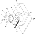
- the alignment unit has a disk 4, on the upper side of which arms 5 each extend in the radial direction.
- the alignment unit is supported on the edge area of the bore, i.e. on the floor 1 or on the floor covering 8 applied to the floor 1.
- the thickness of the floor covering can be taken into account by means of the adjusting screws 20, so that the arms 5 are arranged at the intended height above the floor. This is because the floor covering can also be applied subsequently in the edge region of the borehole if it was not initially present or was destroyed and/or at least partially removed as a result of the production of the stepped borehole.
- the disk 4 held by the arms 5 can be arranged in the intended position.
- the stepped bore introduced into the base 1 has a step 7 , an empty pipe 6 laid in the base 1 opening into the region of the stepped bore located below the step 7 .
- a sealing body 2 is introduced into the lower region of the stepped bore, which in the axial direction, ie in the direction of the bore axis of the stepped bore, covers the region axially covered by the mouth region.
- the sealing body 2 extends axially into the area covered axially by the ring frame 3 .
- the gap area present between the step 7 and the ring frame 3 is covered and casting compound 30 can be filled into this gap area.
- the gap area extends radially between the base 1 and the annular frame 3 and axially up to the step 7.
- the annular frame 3 is spaced apart from the base 1, in particular from the wall of the stepped bore, both in the radial direction and in the axial direction.
- casting compound 30 can be filled into the gap surrounding the ring frame 3 .
- the penetration of the sealing compound 30 into the area of the stepped bore is prevented by the sealing body 2.
- the compensating means in particular the disc 4 with arms 5, can be removed.
- the annular frame 3 is thus held in a materially bonded manner by means of the casting compound 30 and is therefore connected to the floor 1 .
- the sealing body 2 has a centrally arranged, axially continuous hole, so that it can be easily removed from the region of the stepped bore with a finger.
- the sealing body 2 is made from a foam material, in particular plastic, and is in particular in the shape of a torus.
- the sealing body 2 is hollow and has a skin made of rubber or plastic forming the surface, whereby it can be inflated with compressed air and when inflated it nestles against the wall of the stepped bore lying axially below the step 7 of the stepped bore and also on the ring frame, limiting the gap 3 is present. After the casting compound 30 has been poured in, the air is then let out of the sealing body 2 .
- figure 5 is one to run after Figures 1 to 4 alternative orientation of the ring frame 3 shown on the stepped bore.
- the ring frame 3 has axially directed threaded holes on its circumference, into which threaded pins 50 can be screwed, so that they enable the ring frame 3 to be supported on the step 7 of the stepped hole.
- the position of the ring frame 3 can be determined, in particular the height of the ring frame 3.
- the axially upper edge region of the ring frame 3 is the same as in the embodiment according to FIG Figure 1 to 4 brought to the height of the floor covering 8, so that at the latest after the repair or application of the floor covering 8 of the ring frame 3 is arranged in the intended height.
- a spiral rectangular winding 61 is accommodated in a corresponding spirally rectangular groove which is arranged on the underside of a cover part 62 .
- the cover part 62 acts as a winding carrier for the winding 61.
- the cover part 62 has a circular, ie circular-cylindrical outer circumference.
- the cover part 62 is connected to a receiving part 63 .
- a ferrite layer 60 is accommodated in the receiving part 63, which essentially fills a circular plate-like, ie circular-cylindrical spatial area, the ferrite layer preferably being composed of small, parallelepiped-shaped ferrite parts arranged next to one another.
- the ferrite layer 60 is therefore arranged between the cover part 62 and the receiving part 63 .
- the spatial area filled by the ferrite layer 60 is delimited by the cover part 62 and the receiving part 63 .
- the receiving part 63 is screw-connected to the frame part 3 by means of screws 69 passing through the cover part 62 and through the receiving part 63 . That points to this Frame part 3 corresponding to axially directed threaded holes, in which the screws 69 are at least partially screwed.
- the underside of the receiving part 63 ie the side of the receiving part 63 facing away from the cover part 62, is covered by a lower part 64, in particular a lower cover part.
- a lower part 64 in particular a lower cover part.
- an annular spatial area is formed between the receiving part 63 and the lower part 64, in which a printed circuit board 67 is arranged.
- the ring-shaped spatial area runs all the way around in the circumferential direction, that is to say without interruption in the circumferential direction.
- capacitors are fitted, which are connected to the winding 61 in parallel or in series.
- the resonant frequency of the resonant circuit created in this way corresponds to the frequency of the current injected into the winding by a feed device.
- the power is supplied from the feed device, which is not shown in the figures, via a line 66, i.e. a cable which is routed through the empty tube 6 and through a cable gland 65 to the printed circuit board 67.
- the housing of the cable gland 65 is on the underside of the lower part 64, ie arranged on the side of the lower part 64 facing away from the receiving part 63 .
- a controllable light source Arranged centrally between the receiving part 63 and the lower part 64 is another spatial area in which a controllable light source can be provided.
- the bore is preferably filled with a transparent substance.
- the light source can be controlled in such a way that the light source can be switched on or off and/or that the color of the light source can be controlled. In this way, different operating states or other information can be displayed.
- the winding 61 is designed as a flat ring winding.
- the ring winding is designed in the form of a circular spiral.
- the handset can be rotated on the charging point during the transfer of energy, without the inductive coupling between the winding 61 and the secondary winding, which is arranged on the mobile part and preferably also designed as a flat circular spiral-shaped ring winding, fluctuating.
- the time of changing the steering angle of a mobile part with a tank drive or other omnidirectional drive can be used for an inductive transmission of energy to the mobile part.
- the lower part 64 is screwed to the receiving part 63 by means of screws 68 .
- a seal 81 is arranged between the cover part 62 and the receiving part 63, which is arranged on a larger diameter than the ferrite layer 60 and than the winding 61.
- the seal 81 is preferably designed as an O-ring.
- a seal 80 is also arranged between the lower part 64 and the receiving part 63, which seals off the spatial area accommodating the printed circuit board 67 from the outside environment.
- the ferrite layer 60 is arranged in a recess 100 arranged on the receiving part 63 .
- This recess 100 is arranged on the upper side, ie on the side facing the cover part 62, of the receiving part 63.
- the receiving part 63 has two axially continuous recesses 90 spaced apart from one another, so that connection lines, such as the supply line 66, to the printed circuit board 67 can be passed through.
- the recesses 63 open into the depression 100 on the upper side of the receiving part 63.
- the lower part 64 has an annular wall 101 running around in the circumferential direction, which delimits the spatial area arranged centrally between the lower part 64 and the receiving part 63 .
- the lower part 64 has a further annular wall 104 running in the circumferential direction, which is radially spaced from the annular wall 101.
- the spatial area accommodating the printed circuit board 67 is therefore delimited by the annular wall 101 and the annular wall 104.
- the lower part 64 is screw-connected to the receiving part 63 by means of screws 68, the receiving part 63 having axially directed threaded bores for this purpose.
- the cover part 62 has on its side facing the receiving part 63, that is to say the underside, the groove 113 which runs in a rectangular spiral shape and into which the winding 61 is inserted.
- the winding wire ends of the winding 61 designed as a flat winding are led out to adapter circuit boards 111, on each of which an electrical connection part 112 is fitted. An electrical connection is thus provided in a simple manner.
- the adapter boards 111 ie printed circuit boards, are screw-connected and thus electrically connected to busbars 110, which are electrically connected to conductor tracks on the printed circuit board 67.
- the busbars 110 are arranged on the side of the ferrite layer facing away from the cover part 60 .
- the seal 81 can preferably be designed as a foam seal.
- the annular walls 101 and 104 formed on the lower part 64 are arranged on the side of the lower part 64 facing the receiving part 63 .
- the annular walls 101 and 104 touch the receiving part 63, so that the annular spatial area is formed radially between them, in which the printed circuit board 67 is arranged.
Landscapes
- Engineering & Computer Science (AREA)
- Power Engineering (AREA)
- Computer Networks & Wireless Communication (AREA)
- Transportation (AREA)
- Mechanical Engineering (AREA)
- Manufacturing & Machinery (AREA)
- Charge And Discharge Circuits For Batteries Or The Like (AREA)
- Casings For Electric Apparatus (AREA)
- Discharge Lamps And Accessories Thereof (AREA)
- Details Of Aerials (AREA)
Description
- Die Erfindung betrifft ein Verfahren zum Herstellen eines Systems zur induktiven Übertragung von Energie an ein Mobilteil.
- Es ist allgemein bekannt, dass Energie induktiv von einem Primärteil an eine Sekundärwicklung übertragbar ist.
- Aus der
FR 2 775 383 A1 - Aus der
WO 2011 / 154993 A1 ist ebenfalls ein Transformator bekannt. - Aus der
DE 10 2013 007 850 A1 ist eine Transformatoranordnung bekannt. - Aus der
US 2016 / 308391 A1 ist wegebewegbares induktives Leistungsübertragungselement bekannt. - Der Erfindung liegt daher die Aufgabe zugrunde, die Sicherheit bei einem System zur induktiven Beladung weiterzubilden.
- Erfindungsgemäß wird die Aufgabe bei dem Verfahren nach den in Anspruch 1 angegebenen Merkmalen gelöst.
- Wichtige Merkmale der Erfindung bei dem Verfahren zum Herstellen eines Systems zur induktiven Übertragung von Energie an ein Mobilteil, sind, dass
- in einem ersten Verfahrensschritt in einen Boden eine Stufenbohrung eingebracht wird,
- wobei in einem nachfolgenden zweiten Verfahrensschritt ein Dichtkörper in die Stufenbohrung eingebracht wird,
- wobei in einem nachfolgenden dritten Verfahrensschritt ein Ringrahmen mittels einer an der Oberfläche des Bodens abgestützten Ausrichteinheit in der Stufenbohrung gehalten wird, insbesondere wobei die Oberkante des Ringrahmens auf die Höhe des Bodens oder auf die Oberfläche eines auf dem Boden angebrachten Bodenbelags ausgerichtet ist, insbesondere also die Oberkante auf gleicher Höhenposition gebracht wird wie die Oberfläche des Bodens oder des Bodenbelags,
- wobei der Ringrahmen vom Boden beabstandet ist, so dass ein Spaltbereich zwischen Ringrahmen und Boden vorhanden ist,
- wobei in einem nachfolgenden vierten Verfahrensschritt Vergussmasse in den Spaltbereich gefüllt wird,
- wobei in einem nachfolgenden fünften Verfahrensschritt die Ausrichteinheit entfernt wird,
- wobei in einem nachfolgenden sechsten Verfahrensschritt ein Primärteil im Ringrahmen aufgenommen wird, insbesondere schraubverbunden wird.
- Von Vorteil ist dabei, dass eine Ausrichtung des Ringrahmens an der Oberfläche des Bodens, insbesondere an der genauen Höhe des Bodenbelags auf dem Boden, ausführbar ist. Somit ist das Primärteil mit dem Ringrahmen einfach verbindbar und es ist das Entstehen einer Stolperkante verhindert. Diese Barrierefreiheit verringert also die Unfallgefahr und verbessert somit die Sicherheit.
- Bei einer vorteilhaften Ausgestaltung liegt der Dichtkörper an der Stufenbohrung, insbesondere an einem unterhalb der Stufe der Stufenbohrung angeordneten Bereich der Stufenbohrung an, insbesondere ist angedrückt, und an dem Ringrahmen, insbesondere an der Innenwand des ringförmigen Ringrahmens. Von Vorteil ist dabei, dass mittels des Dichtkörpers verhindert wird, dass Vergussmasse in den für das Primärteil und/oder für seine Zuleitung vorgesehenen Raumbereich der Stufenbohrung einströmt. Entweder ist der Dichtkörper aus einem elastischen Kunststoff-Material, wie Schaumstoff, gefertigt und weist ein mittig angeordnetes Loch auf oder der Dichtkörper ist aufblasbar ausgeführt, so dass er sich beim Aufblasen an den unteren Bereich der Stufenbohrung und an die Innenwandung des Ringrahmens anlegt. In jedem Fall ist der für die Vergussmasse vorgesehene Spaltbereich zwischen Ringrahmen und Boden zumindest auch begrenzt durch den Dichtkörper.
- Bei einer vorteilhaften Ausgestaltung weist das Primärteil eine Wicklung auf,
insbesondere wobei eine elektrische Zuleitung für die Wicklung in einem Leerrohr angeordnet ist, welches in den unterhalb der Stufe der Stufenbohrung angeordneten Bereich mündet. Von Vorteil ist dabei, dass die Zuleitung zur Zuleitung eines mittelfrequenten Wechselstroms gut geschützt zum Ladepunkt, also auch zum Primärteil, anordenbar ist. - Bei einer vorteilhaften Ausgestaltung wird die Ausrichteinheit an der Oberfläche des Bodenbelags des Bodens ausgerichtet. Von Vorteil ist dabei, dass ein Ausrichten an der Oberfläche und somit an dem Bodenbelag vorhandenen Bodenniveau ermöglicht ist.
- Bei einer vorteilhaften Ausgestaltung ist der Ringrahmen oberhalb der Stufe der Stufenbohrung angeordnet. Von Vorteil ist dabei, dass das Primärteil präzise einbaubar ist.
- Wichtige Merkmale des nach einem vorgenannten Verfahren hergestellten Systems sind, dass die Vorrichtung ein in einer in einem Boden eingebrachten Stufenbohrung angeordnetes Primärteil aufweist,
- wobei die Ausrichteinheit eine Scheibe aufweist, an welcher radial sich erstreckende Arme angeordnet sind, an welchen jeweils eine Einstellschraube angeordnet ist.
- und/oder wobei
- ein Ringrahmen in der in den Boden eingebrachten Stufenbohrung mittels Vergussmasse gehalten ist, insbesondere stoffschlüssig und/oder formschlüssig,
- wobei das Primärteil mit dem Ringrahmen verbunden ist, insbesondere schraubverbunden ist.
- Von Vorteil ist dabei, dass die Vorrichtung einfach herstellbar ist und das Primärteil präzise einbaubar ist, insbesondere also die Einbauhöhe präzise abgestimmt ist auf die Oberfläche des Bodens, insbesondere des Bodenbelags.
- Bei einer vorteilhaften Ausgestaltung weist das Primärteil ein Aufnahmeteil auf, dessen Oberseite von einem Deckelteil abgedeckt ist, welches an seiner dem Aufnahmeteil zugewandten Seite eine spiralförmig verlaufende Nut aufweist, in welcher die Wicklung aufgenommen ist, insbesondere wobei die Wicklung als Flachwicklung ausgeführt ist,
- wobei auf der dem Aufnahmeteil zugewandten Seite der Wicklung eine Ferritschicht angeordnet ist,
- insbesondere wobei die Ferritschicht aus quaderförmigen Ferritteilen zusammengesetzt ist. Von Vorteil ist dabei, dass das Primärteil rund ausführbar ist und somit an die Stufenbohrung angepasst ist. Trotz der runden Form ist aber eine Wicklung aufnehmbar, die als rechteckspiralförmige Wicklung, also nicht isotrop in der Verfahrebene des Mobilteils, ausführbar ist. Somit ist ein hoher induktiver Kopplungsgrad zwischen Primärteil und Sekundärwicklung erreichbar, da die ebenfalls nicht isotrope Sekundärwicklung besonders vorteilhaft ist zur induktiven Beladung aus einem entlang des Fahrwegs langgestreckt verlegten Primärleiters. Die Beladung ist also nicht nur von erfindungsgemäßen Ladepunkten aus, sondern auch von langgestreckt verlegten Primärleitern aus ermöglicht. Die Wicklung des Primärteils des Ladepunktes und die Sekundärwicklung des Mobilteils weisen also jeweils eine Vorzugsrichtung auf.
- Bei einem System, bei welchem das Beladen jedoch nur an den Ladepunkten ausgeführt werden soll, ist die Wicklung im Primärteil als kreisspiralförmige Flachwicklung ausführbar, also ohne Vorzugsrichtung. Somit ist eine Beladung des Mobilteils während des Ausführung einer Verdrehung des Mobilteils über dem Ladepunkt ermöglicht. Hierzu weist das Mobilteil einen omnidirektionalen Antrieb auf, kann sich also auf der Stelle drehen. Die Drehachse ist dabei vorzugsweise koaxial zur Achse der Stufenbohrung ausgerichtet.
- Bei einer vorteilhaften Ausgestaltung ist an der vom Deckelteil abgewandten Seite des Aufnahmeteils ein Unterteil mit dem Aufnahmeteil verbunden,
wobei zwischen Aufnahmeteil und Unterteil ein in Umfangsrichtung umlaufender, insbesondere ringförmiger Raumbereich ausgebildet ist, in welchem eine mit zumindest einer Kondensatoranordnung bestückte Leiterplatte angeordnet ist. Von Vorteil ist dabei, dass im Raumbereich eine elektrische Kompensation anordenbar ist. - Bei einer vorteilhaften Ausgestaltung ist das Unterteil mit dem Aufnahmeteil schraubverbunden,
wobei das Deckelteil mittels durch das Aufnahmeteil durchgehender Schrauben mit dem Ringrahmen schraubverbunden ist. Von Vorteil ist dabei, dass eine einfache Verbindung ausführbar ist. - Bei einer vorteilhaften Ausgestaltung ist zwischen Aufnahmeteil und Unterteil ein vom in Umfangsrichtung umlaufenden, insbesondere ringförmigen, Raumbereich beabstandeter, insbesondere auf kleinerem Radialabstand zur Mittelachse der Stufenbohrung angeordneter, weiterer Raumbereich ausgebildet. Von Vorteil ist dabei, dass ein Leuchtmittel in diesem weiteren Raumbereich vorsehbar ist, welches mittig, also im Bereich der Achse der Stufenbohrung, angeordnet ist.
- Bei einer vorteilhaften Ausgestaltung ist ein steuerbares Leuchtmittel, insbesondere LED, im weiteren Raumbereich angeordnet,
- wobei das Aufnahmeteil eine insbesondere zum Leuchtmittel, durchgehende Bohrung aufweist, die entweder frei gehalten ist oder mit einem transparenten Material befüllt ist,
- wobei das Deckelteil aus einem transparenten Material gefertigt ist. Von Vorteil ist dabei, dass
- Informationen optisch anzeigbar sind, beispielsweise der Betriebszustand des Primärteils.
- Bei einer vorteilhaften Ausgestaltung ist die Kondensatoranordnung mit der Wicklung in Reihe oder parallelgeschaltet und derart dimensioniert, dass die Resonanzfrequenz des so gebildeten Schwingkreises im Wesentlichen der Frequenz des in den Schwingkreis oder die Wicklung eingeprägten Wechselstroms entspricht. Von Vorteil ist dabei, dass ein hoher Wirkungsgrad erreichbar ist.
- Bei einer vorteilhaften Ausgestaltung ist an der Unterseite des Unterteils eine Kabelverschraubung angeordnet, zu welcher die Zuleitung geführt ist. Von Vorteil ist dabei, dass ein geschütztes Zuführen der Zuleitung ausführbar ist.
- Bei einer vorteilhaften Ausgestaltung weisen das Aufnahmeteil, das Deckelteil und das Unterteil einen kreisförmigen Außenrandbereich auf
und/oder einen maximalen Radialabstand, welcher unabhängig vom Umfangswinkel ist. Von Vorteil ist dabei, dass das Primärteil in den ringrahmen aufnehmbar ist, welcher in der Stufenbohrung angeordnet ist, die als Rundbohrung ausgeführt ist. Somit ist die Herstellung einfach. - Bei einer vorteilhaften Ausgestaltung weist die Wicklung eine Vorzugsrichtung auf, die parallel zur Verfahrebene des Mobilteils ausgerichtet ist,
und/oder der maximale Radialabstand der Wicklung weist abhängig vom Umfangswinkel verschiedenen Werte auf. Von Vorteil ist dabei, dass zwar eine optimale Beladung des Mobilteils nur in einer Ausrichtung des Mobilteils ermöglicht ist, bei welcher die Vorzugsrichtung der Sekundärwicklung des Mobilteils parallel gerichtet ist zur Vorzugsrichtung der Wicklung des Primärteils. Aber somit ist auch eine Beladung während der Fahrt entlang eines langgestreckt verlegten Primärleiters ermöglicht. - Bei einer alternativen Ausführung der Wicklung ohne Vorzugsrichtung, also als kreisförmige Flachwicklung, die koaxial zur Achse der Stufenbohrung ausgerichtet ist, ist eine Beladung während der Drehbewegung des Mobilteils ermöglicht, ohne dass die induktive Kopplungsstärke zwischen Wicklung und Sekundärwicklung schwanken würde. Die Drehachse muss dabei koaxial zur Achse der Stufenbohrung ausgerichtet sein. Vorzugsweise weist das Mobilteil hierzu omnidirektionale Räder auf oder einen Panzerantrieb. Somit ist die Drehung auf der Stelle ausführbar.
- Wichtige Merkmale bei dem System zur kontaktlosen Übertragung von Energie von einem am Boden angeordneten Primärteil an ein auf dem Boden bewegbares Mobilteil, wobei das System nach einem vorgenannten Verfahren hergestellt ist., sind, dass ein Ringrahmen in einer in den Boden eingebrachten Stufenbohrung mittels Vergussmasse gehalten ist, insbesondere stoffschlüssig und/oder formschlüssig,
das Primärteil mit dem Ringrahmen verbunden ist, insbesondere schraubverbunden ist. - Von Vorteil ist dabei, dass ein präzises Aufnehmen des Primärteils im Ringrahmen in einfacher Weise ausführbar ist.
- Weitere Vorteile ergeben sich aus den Unteransprüchen. Die Erfindung ist nicht auf die Merkmalskombination der Ansprüche beschränkt. Für den Fachmann ergeben sich weitere sinnvolle Kombinationsmöglichkeiten von Ansprüchen und/oder einzelnen Anspruchsmerkmalen und/oder Merkmalen der Beschreibung und/oder der Figuren, insbesondere aus der Aufgabenstellung und/oder der sich durch Vergleich mit dem Stand der Technik stellenden Aufgabe.
- Die Erfindung wird nun anhand von Abbildungen näher erläutert:
- In der
Figur 1 ist eine Schrägansicht einer angeschnittenen explodierten Darstellung eines Herstellschritts zur Herstellung einer Primäreinheit, insbesondere Ladepunkt, eines Systems zur induktiven Übertragung von Energie an ein Mobilteil dargestellt, wobei ein Ringrahmen 3 am Rand einer Stufenbohrung mittels einer Ausrichteinheit ausgerichtet wird. - In der
Figur 2 ist eine zugehörige Draufsicht auf den Zusammenbau dargestellt. - In der
Figur 3 ist eine zugehörige Schnittansicht dargestellt. - In der
Figur 4 ist eine Schrägansicht durch eine angeschnittene explodierte Darstellung des Zusammenbaus gezeigt. - In der
Figur 5 ist eine alternative Methode zum Ausrichten des Ringrahmens 3 gezeigt. - In der
Figur 6 ist ein Querschnitt durch die Primäreinheit dargestellt. - In der
Figur 7 ist eine Schrägansicht auf die angeschnitten dargestellte in der Stufenbohrung angeordnete Primäreinheit gezeigt. - In der
Figur 8 ist eine Schrägansicht auf die angeschnitten dargestellte Primäreinheit gezeigt. - In der
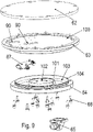
Figur 9 ist eine explodierte Darstellung der Primäreinheit gezeigt. - In der
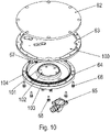
Figur 10 ist die explodierte Darstellung der Primäreinheit aus einem anderen Blickwinkel gezeigt. - In der
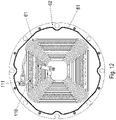
Figur 11 ist der Bereich der Wicklung 61 der Primäreinheit explodiert dargestellt, wobei die Blickrichtung von unten herkommend gewählt ist. - In der
Figur 12 ist eine Draufsicht von unten auf diesen Bereich bei Zusammenbau der Teile dargestellt. - Wie in den Figuren gezeigt, wird eine Primäreinheit im Boden angeordnet, wobei die Primäreinheit eine Wicklung 61 aufweist, in welche ein mittelfrequenter Strom eingeprägt wird. Somit ist ein über der Primäreinheit, insbesondere also Ladepunkt, eingeparktes oder sich drehendes Mobilteil induktiv mit Energie beladbar. Hierzu weist das Mobilteil an seiner Unterseite eine Sekundärwicklung auf, der eine derartige Kapazität parallel oder in Reihe zugeschaltet ist, dass die Resonanzfrequenz des so gebildeten Schwingkreises der Frequenz des in die Wicklung 61 eingeprägten Stromes entspricht.
- Zur Herstellung des Ladepunktes wird zunächst eine Kernbohrung im Bodenmaterial 1 insbesondere Beton, ausgeführt. Der Boden weist an seiner Oberseite einen Bodenbelag 8 auf und ist vom Mobilteil befahrbar.
- Um den Ladepunkt barrierefrei zu gestalten, also keine Stolperfalle auszubilden, wird zunächst ein Ringrahmen 3 mit einer Ausrichteinheit ausgerichtet und gehalten. Dabei ist die Ausrichteinheit abgestützt am Rand der Bohrung,
Die Ausrichteinheit weist eine Scheibe 4 auf, an deren Oberseite Arme 5 sich jeweils in radiale Richtung erstrecken. Mittels axial orientierter Einstellschrauben 20 wird die Ausrichteinheit am Randbereich der Bohrung abgestützt, also am Boden 1 oder am auf dem Boden 1 aufgebrachten Bodenbelag 8. - Bei Abstützung am Boden 1 ist mittels der Einstellschrauben 20 die Dicke des Bodenbelags berücksichtigbar, so dass die Arme 5 in der vorgesehenen Höhe über dem Boden angeordnet sind. Denn nachträglich ist auch im Randbereich der Bohrung der Bodenbelag aufbringbar, falls er anfangs noch nicht vorhanden war oder durch das Herstellen der Stufenbohrung zerstört und/oder zumindest teilweise entfernt wurde.
- Somit ist mittels der durch die Arme 5 durchgeschraubten Einstellschrauben 20 die von den Armen 5 gehaltene Scheibe 4 in der vorgesehenen Position anordenbar.
- Die in den Boden 1 eingebrachte Stufenbohrung weist eine Stufe 7 auf, wobei in den unterhalb der Stufe 7 angeordneten Bereich der Stufenbohrung ein Leerrohr 6 mündet, welches im Boden 1 verlegt ist.
- Wie in
Figur 1 bis 4 gezeigt, wird ein Dichtkörper 2 in den unteren Bereich der Stufenbohrung eingebracht, welcher in axialer Richtung, also in Richtung der Bohrungsachse der Stufenbohrung, den vom Mündungsbereich axial überdeckten Bereich überdeckt. Außerdem erstreckt sich der Dichtkörper 2 axial bis in den vom Ringrahmen 3 axial überdeckten Bereich. Somit ist der zwischen der Stufe 7 und dem ringrahmen 3 vorhandene Spaltbereich überdeckt und es ist Vergussmasse 30 in diesen Spaltbereich einfüllbar. Der Spaltbereich erstreckt sich radial zwischen Boden 1 und Ringrahmen 3 und axial bis zur Stufe 7. Sowohl in radialer Richtung als auch in axialer Richtung ist der Ringrahmen 3 vom Boden 1, insbesondere von der Wandung der Stufenbohrung, beabstandet. - Da der Ringrahmen 3 vom Ausgleichsmittel, also der Scheibe 4, gehalten ist, insbesondere mittels Verbindungsschrauben 21, ist in den den Ringrahmen 3 umgebenden Spalt Vergussmasse 30 einfüllbar. Das Vordringen der Vergussmasse 30 in den Bereich der Stufenbohrung ist verhindert mittels des Dichtkörpers 2.
- Somit ist nach Aushärten der Vergussmasse 30 das Ausgleichsmittel, insbesondere die Scheibe 4 mit Armen 5, entfernbar. Der Ringrahmen 3 ist somit mittels der Vergussmasse 30 stoffschlüssig gehalten und daher mit dem Boden 1 verbunden.
- Der Dichtkörper 2 weist ein mittig angeordnetes axial durchgehendes Loch auf, so dass er mit einem Finger in einfacher Weise aus dem Bereich der Stufenbohrung entnehmbar ist.
- Der Dichtkörper 2 ist aus einem Schaumstoff, insbesondere Kunststoff, gefertigt, insbesondere torusförmig. Alternativ ist der Dichtkörper 2 hohl und mit einer die Oberfläche bildenden Haut aus Gummi oder Kunststoff ausgeführt, wobei er mit Druckluft aufblasbar ist und sich beim Aufblasen an die axial unterhalb der Stufe 7 der Stufenbohrung liegende Wandung der Stufenbohrung anschmiegt sowie den Spalt begrenzend auch am Ringrahmen 3 anliegt. Nach Einfüllen der Vergussmasse 30 wird dann die Luft aus dem Dichtkörper 2 herausgelassen.
- In
Figur 5 ist eine zur Ausführung nachFiguren 1 bis 4 alternative Ausrichtung des Ringrahmens 3 an der Stufenbohrung gezeigt. - Dabei weist der Ringrahmen 3 an seinem Umfang axial gerichtete Gewindebohrungen auf, in welche Gewindestifte 50 einschraubbar sind, so dass diese ein Abstützen des Ringrahmens 3 an der Stufe 7 der Stufenbohrung ermöglichen.
- Somit ist durch ein Anpassen mittels Schrauben der Gewindestifte 50 die Position des Ringrahmens 3 bestimmbar, insbesondere die Höhe des Ringrahmens 3. Der axial obere Randbereich des Ringrahmens 3 wird dabei wie bei der Ausführung nach
Figur 1 bis 4 auf die Höhe des Bodenbelags 8 gebracht, so dass spätestens nach dem Ausbessern oder Aufbringen des Bodenbelags 8 der Ringrahmen 3 in der vorgesehenen Höhe angeordnet ist. - Danach wird auch bei der Ausführung nach
Figur 5 die Vergussmasse 30 eingebracht. Die Gewindestifte 50 verbleiben dabei in der Vergussmasse 30. - In der
Figur 6 ist der nach dem Aushärten der Vergussmasse 30 und Entfernen des Dichtkörpers 2 herzustellende Ladepunkt im Querschnitt gezeigt. - Dabei ist eine spiralförmige Rechteckwicklung 61 in einer entsprechend spiralförmig rechteckig verlaufende Nut aufgenommen, welche an der Unterseite eines Deckelteil 62 angeordnet ist. Das Deckelteil 62 fungiert als Wicklungsträger für die Wicklung 61.
- Das Deckelteil 62 weist einen kreisförmigen, also kreiszylindrischen Außenumfang auf.
- Das Deckelteil 62 ist mit einem Aufnahmeteil 63 verbunden. Dabei ist im Aufnahmeteil 63 eine Ferritschicht 60 aufgenommen, welche einen kreisplattenartigen, also kreiszylindrischen Raumbereich im Wesentlichen füllt, wobei die Ferritschicht vorzugsweise aus kleinen, nebeneinander angeordneten, quaderförmigen Ferritteilen zusammengesetzt ist.
- Die Ferritschicht 60 ist also zwischen dem Deckelteil 62 und dem Aufnahmeteil 63 angeordnet. Der von der Ferritschicht 60 befüllte Raumbereich ist von dem Deckelteil 62 und dem Aufnahmeteil 63 begrenzt.
- Das Aufnahmeteil 63 ist mittels durch das Deckelteil 62 und durch das Aufnahmeteil 63 durchgehenden Schrauben 69 mit dem Rahmenteil 3 schraubverbunden. Hierzu weist das Rahmenteil 3 entsprechend axial gerichtete Gewindebohrungen auf, in welche die Schrauben 69 zumindest teilweise eingeschraubt sind.
- Die Unterseite des Aufnahmeteils 63, also die vom Deckelteil 62 abgewandte Seite des Aufnahmeteils 63, ist mittels eines Unterteils 64, insbesondere Unterdeckteil, abgedeckt. Hierbei ist zwischen Aufnahmeteil 63 und Unterteil 64 ein ringförmiger Raumbereich ausgebildet, in welchem eine Leiterplatte 67 angeordnet ist. Der ringförmige Raumbereich ist in Umfangsrichtung umlaufend ausgeführt, also ohne Unterbrechung in Umfangsrichtung.
- Auf der Leiterplatte 67 sind Kondensatoren bestückt, welche mit der Wicklung 61 parallel oder in Reihe geschaltet sind. Die Resonanzfrequenz des so entstandenen Schwingkreises entspricht der Frequenz des von einem Einspeisegerät in die Wicklung eingeprägten Stromes.
- Die Zuführung des Stromes von dem in den Figuren nicht gezeigten Einspeisegerät erfolgt über eine Leitung 66, also Kabel, welche durch das Leerrohr 6 und durch eine Kabelverschraubung 65 geführt sind zur Leiterplatte 67. Das Gehäuse der Kabelverschraubung 65 ist an der Unterseite des Unterteils 64, also an der vom Aufnahmeteil 63 abgewandten Seite des Unterteils 64 angeordnet.
- Mittig angeordnet ist zwischen Aufnahmeteil 63 und Unterteil 64 ein weiterer Raumbereich, in welchem ein steuerbares Leuchtmittel vorsehbar ist. Somit ist es ermöglicht, Information durch das Leuchtmittel anzuzeigen, wobei hierzu eine axial durch das Aufnahmeteil durchgehende Bohrung vorzunehmen ist, und das deckelteil entweder aus einem transparenten Kunststoff gefertigt ist oder ein über der Bohrung angeordneter Bereich des Deckelteils ist aus einem transparenten Stoff gefertigt. Die Bohrung ist vorzugsweise befüllt mit einem transparenten Stoff. Das Leuchtmittel ist derart steuerbar, dass das Leuchtmittel anschaltbar oder ausschaltbar ist und/oder dass die Farbe des Leuchtmittels steuerbar ist. Auf diese Weise sind verschiedene Betriebszustände oder auch andere Informationen anzeigbar.
- Bei einem anderen erfindungsgemäßen Ausführungsbeispiel ist die Wicklung 61 als flache Ringwicklung ausgeführt. Dabei ist die Ringwicklung kreisspiralförmig ausgeführt. Auf diese Weise ist das Mobilteil während der Übertragung von Energie auf dem Ladepunkt drehbar, ohne dass die induktive Kopplung zwischen der Wicklung 61 und der am Mobilteil angeordneten, vorzugsweise ebenfalls als flache kreisspiralförmige Ringwicklung ausgeführte Sekundärwicklung schwankt. Somit ist die Zeit der Änderung des Lenkwinkels eines Mobilteils mit Panzerantrieb oder anderem omnidirektionalem Antrieb nutzbar für eine induktive Übertragung von Energie an das Mobilteil.
- Das Unterteil 64 ist mittels Schrauben 68 am Aufnahmeteil 63 angeschraubt.
- Wie in
Figur 8 gezeigt, ist zwischen Deckelteil 62 und Aufnahmeteil 63 ist eine Dichtung 81 angeordnet, welche auf größerem Durchmesser als die Ferritschicht 60 und als die Wicklung 61 angeordnet ist. Die Dichtung 81 ist vorzugsweise als O-Ring ausgeführt. - Zwischen Unterteil 64 und Aufnahmeteil 63 ist ebenfalls eine Dichtung 80 angeordnet, welche den die Leiterplatte 67 aufnehmenden Raumbereich zur äußeren Umgebung hin abdichtet.
- Wie in
Figur 9 undFigur 10 gezeigt, ist die Ferritschicht 60 in einer am Aufnahmeteil 63 angeordneten Vertiefung 100 angeordnet. Diese Vertiefung 100 ist dabei an der Oberseite, also an der dem Deckelteil 62 zugewandten Seite, des Aufnahmeteils 63 angeordnet. - Das Aufnahmeteile 63 weist zwei voneinander beabstandete axial durchgehende Ausnehmungen 90 auf, so dass Anschlussleitungen, wie Zuleitung 66, zur Leiterplatte 67 durchführbar sind.
- Die Ausnehmungen 63 münden an der Oberseite des Aufnahmeteils 63 in die Vertiefung 100.
- Das Unterteil 64 weist eine in Umfangsrichtung umlaufende Ringwand 101 auf, welche den mittig zwischen Unterteil 64 und Aufnahmeteil 63 angeordneten Raumbereich begrenzt.
- Außerdem weist das Unterteil 64 eine weitere in Umfangsrichtung umlaufende Ringwand 104 auf, welche radial beabstandet ist von der Ringwand 101. Somit ist der die Leiterplatte 67 aufnehmende Raumbereich begrenzt durch die Ringwand 101 und die Ringwand 104.
- Das Unterteil 64 ist mittels Schrauben 68 mit dem Aufnahmeteil 63 schraubverbunden, wobei das Aufnahmeteil 63 hierzu axial gerichtete Gewindebohrungen aufweist.
- Wie in
Figur 11 gezeigt, weist das Deckelteil 62 an seiner dem Aufnahmeteil 63 zugewandten Seite, also Unterseite, die rechteck-spiralförmig verlaufende Nut 113 auf, in welche die Wicklung 61 eingelegt wird. - Die Wicklungsdrahtenden der als Flachwicklung ausgeführten Wicklung 61 sind zu Adapterplatinen 111 herausgeführt, auf denen jeweils ein elektrisches Anschlussteil 112 bestückt ist. Somit ist eine elektrische Verbindung in einfacher Weise bereitgestellt. Die Adapterplatinen 111, also Leiterplatten, sind schraubverbunden und somit elektrisch verbunden mit Stromschienen 110, welche elektrisch mit Leiterbahnen der Leiterplatte 67 verbunden sind.
- Die Stromschienen 110 sind auf der vom Deckelteil 60 abgewandten Seite der Ferritschicht angeordnet.
- Die Dichtung 81 ist vorzugsweise als Schaumdichtung ausführbar.
- Die am Unterteil 64 ausgeformten Ringwände 101 und 104 sind auf der dem Aufnahmeteil 63 zugewandten Seite des Unterteils 64 angeordnet. Die Ringwände 101 und 104 berühren die das Aufnahmeteil 63, so dass radial zwischen ihnen der ringförmige Raumbereich ausgebildet ist, in welchem die Leiterplatte 67 angeordnet ist.
-
- 1 Boden, insbesondere Beton
- 2 Dichtkörper
- 3 Ringrahmen
- 4 Scheibe, insbesondere Kreisscheibe
- 5 Arm
- 6 Leerrohr
- 7 Stufe der Stufenbohrung
- 8 Bodenbelag
- 20 Einstellschraube
- 21 Verbindungsschraube
- 30 Vergussmasse
- 50 Gewindestift
- 60 Ferritschicht
- 61 Wicklung, insbesondere Rechteckwicklung
- 62 Deckelteil als Wicklungsträger
- 63 Aufnahmeteil
- 64 Unterteil, insbesondere Unterdeckteil
- 65 Gehäuse der Kabelverschraubung
- 66 Zuleitung
- 67 Leiterplatte
- 68 Schraube
- 69 Schraube
- 80 Dichtung
- 81 Dichtung
- 90 Ausnehmung
- 100 Vertiefung
- 101 Ringwand
- 102 Vertiefung
- 103 Vertiefung
- 104 Ringwand
- 110 Stromschiene
- 111 Adapterplatine
- 112 elektrisches Anschlussteil
- 113 Nut, insbesondere rechteckwicklungsförmig verlaufende Nut
Claims (3)
- Verfahren zum Herstellen eines Systems zur induktiven Übertragung von Energie von einem am Boden angeordneten Primärteil an ein auf dem Boden bewegbares Mobilteil,
dadurch gekennzeichnet, dassin einem ersten Verfahrensschritt in einen Boden (1) eine Stufenbohrung eingebracht wird,wobei in einem nachfolgenden zweiten Verfahrensschritt ein Dichtkörper (2) in die Stufenbohrung eingebracht wird,wobei in einem nachfolgenden dritten Verfahrensschritt ein Ringrahmen (3) mittels einer an der Oberfläche des Bodens (1) abgestützten Ausrichteinheit in der Stufenbohrung gehalten wird, insbesondere wobei die Oberkante des Ringrahmens (3) auf die Höhe des Bodens (1) oder auf die Oberfläche eines auf dem Boden (1) angebrachten Bodenbelags (8) ausgerichtet ist, insbesondere also die Oberkante auf gleicher Höhenposition gebracht wird wie die Oberfläche des Bodens (1) oder des Bodenbelags (8),wobei der Ringrahmen (3) vom Boden (1) beabstandet ist, so dass ein Spaltbereich zwischen Ringrahmen (3) und Boden (1) vorhanden ist,wobei in einem nachfolgenden vierten Verfahrensschritt Vergussmasse (30) in den Spaltbereich gefüllt wird,wobei in einem nachfolgenden fünften Verfahrensschritt die Ausrichteinheit entfernt wird,wobei in einem nachfolgenden sechsten Verfahrensschritt ein Primärteil im Ringrahmen (3) aufgenommen wird, insbesondere schraubverbunden wird. - Verfahren nach Anspruch 1,
dadurch gekennzeichnet, dass
der Dichtkörper (2) an der Stufenbohrung, insbesondere an einem unterhalb der Stufe (7) der Stufenbohrung angeordneten Bereich der Stufenbohrung anliegt, insbesondere angedrückt ist, und an dem Ringrahmen (3), insbesondere an der Innenwand des ringförmigen Ringrahmens (3). - Verfahren nach mindestens einem der vorangegangenen Ansprüche,
dadurch gekennzeichnet, dassdas Primärteil eine Wicklung (61) aufweist,insbesondere wobei eine elektrische Zuleitung (66) für die Wicklung (61) in einem Leerrohr (6) angeordnet ist, welches in den unterhalb der Stufe (7) der Stufenbohrung angeordneten Bereich mündet,und/oder dassdie Ausrichteinheit an der Oberfläche des Bodenbelags (8) des Bodens (1) ausgerichtet wird,und/oder dassRingrahmen (3) oberhalb der Stufe (7) der Stufenbohrung angeordnet ist.
Applications Claiming Priority (2)
| Application Number | Priority Date | Filing Date | Title |
|---|---|---|---|
| DE102017003498 | 2017-04-07 | ||
| PCT/EP2018/025064 WO2018184730A1 (de) | 2017-04-07 | 2018-03-20 | Verfahren zum herstellen eines systems zur induktiven übertragung von energie an ein mobilteil und vorrichtung zur durchführung des verfahrens |
Publications (2)
| Publication Number | Publication Date |
|---|---|
| EP3607635A1 EP3607635A1 (de) | 2020-02-12 |
| EP3607635B1 true EP3607635B1 (de) | 2022-10-19 |
Family
ID=61750070
Family Applications (1)
| Application Number | Title | Priority Date | Filing Date |
|---|---|---|---|
| EP18712504.2A Active EP3607635B1 (de) | 2017-04-07 | 2018-03-20 | Verfahren zum herstellen eines systems zur induktiven übertragung von energie an ein mobilteil und vorrichtung zur durchführung des verfahrens |
Country Status (5)
| Country | Link |
|---|---|
| US (2) | US11101692B2 (de) |
| EP (1) | EP3607635B1 (de) |
| CN (1) | CN110462973B (de) |
| DE (1) | DE102018002275A1 (de) |
| WO (1) | WO2018184730A1 (de) |
Families Citing this family (7)
| Publication number | Priority date | Publication date | Assignee | Title |
|---|---|---|---|---|
| DE102016219476A1 (de) * | 2016-10-07 | 2018-04-12 | Bayerische Motoren Werke Aktiengesellschaft | Induktive Ladeeinheit für ein Fahrzeug |
| EP3607635B1 (de) * | 2017-04-07 | 2022-10-19 | Sew-Eurodrive GmbH & Co. KG | Verfahren zum herstellen eines systems zur induktiven übertragung von energie an ein mobilteil und vorrichtung zur durchführung des verfahrens |
| DE102018007910A1 (de) * | 2017-10-20 | 2019-04-25 | Sew-Eurodrive Gmbh & Co Kg | System zur berührungslosen Übertragung von elektrischer Energie an ein auf einem Boden einer Anlage verfahrbares Mobilteil |
| EP3704799B1 (de) * | 2017-11-03 | 2022-10-05 | SEW-EURODRIVE GmbH & Co. KG | System zur berührungslosen übertragung von elektrischer energie an ein mobilteil |
| US11063415B2 (en) * | 2019-01-16 | 2021-07-13 | Raymond & Lae Engineering, Inc. | Raised access floor panel with embedded sensors |
| EP3925056A1 (de) * | 2019-02-13 | 2021-12-22 | Sew-Eurodrive GmbH & Co. KG | System zur berührungslosen übertragung elektrische leistung an ein mobilteil |
| US12283447B2 (en) * | 2020-02-18 | 2025-04-22 | Ujniversity of Manitoba | Direct current circuit breaker and related method |
Citations (1)
| Publication number | Priority date | Publication date | Assignee | Title |
|---|---|---|---|---|
| US20160308391A1 (en) * | 2015-04-15 | 2016-10-20 | Wireless Advanced Vehicle Electrification, Inc. | Removable inductive power transfer pad |
Family Cites Families (17)
| Publication number | Priority date | Publication date | Assignee | Title |
|---|---|---|---|---|
| DE3700488A1 (de) | 1987-01-08 | 1988-07-21 | Klaus Dipl Ing Becker | Leistungsuebertrager mit ferromagnetischem kern |
| FR2775383B1 (fr) * | 1998-02-25 | 2000-05-05 | Siraga Sa | Transformateur tournant comportant un corps fixe et un corps rotatif disposes l'un en face de l'autre |
| DE102006025460B4 (de) | 2006-05-30 | 2022-01-20 | Sew-Eurodrive Gmbh & Co Kg | Anlage mit einem Primärleitersystem |
| WO2010062345A2 (en) * | 2008-10-31 | 2010-06-03 | Lam Research Corporation | Lower electrode assembly of plasma processing chamber |
| US9873347B2 (en) | 2009-03-12 | 2018-01-23 | Wendell Brown | Method and apparatus for automatic charging of an electrically powered vehicle |
| DE112010005649T5 (de) | 2010-06-08 | 2013-11-28 | Hitachi, Ltd. | Isoliertransformator und Leistungsquelle |
| US9327608B2 (en) * | 2011-08-04 | 2016-05-03 | Schneider Electric USA, Inc. | Extendable and deformable carrier for a primary coil of a charging system |
| DE102012202472B4 (de) | 2012-02-17 | 2018-03-01 | Siemens Aktiengesellschaft | Vorrichtung zur kontaktlosen Übertragung von Energie auf eine korrespondierende Vorrichtung |
| DE102013007850B4 (de) * | 2013-05-08 | 2023-08-10 | Sew-Eurodrive Gmbh & Co Kg | Transformatoranordnung |
| DE102014000347B4 (de) * | 2014-01-16 | 2022-10-06 | Sew-Eurodrive Gmbh & Co Kg | Primärteil, insbesondere bodengebundenes Primärteil, für ein System zur berührungslosen Energieübertragung |
| US9794033B2 (en) * | 2014-03-14 | 2017-10-17 | Intel IP Corporation | Systems, methods and devices for opportunistic networking |
| US9583256B2 (en) | 2014-06-13 | 2017-02-28 | Verily Life Sciences Llc | Three-dimensional wireless charging coil |
| US9796272B2 (en) * | 2014-08-25 | 2017-10-24 | Bryan Richards | Road bearing for electric vehicle connection |
| US10622142B2 (en) * | 2016-09-26 | 2020-04-14 | Utah State University | Concrete-embedded wireless power transfer coil |
| JP6606047B2 (ja) * | 2016-10-03 | 2019-11-13 | 株式会社東芝 | 送電装置 |
| CN108538744B (zh) * | 2017-03-01 | 2021-03-02 | 北京北方华创微电子装备有限公司 | 卡盘装置以及半导体加工设备 |
| EP3607635B1 (de) * | 2017-04-07 | 2022-10-19 | Sew-Eurodrive GmbH & Co. KG | Verfahren zum herstellen eines systems zur induktiven übertragung von energie an ein mobilteil und vorrichtung zur durchführung des verfahrens |
-
2018
- 2018-03-20 EP EP18712504.2A patent/EP3607635B1/de active Active
- 2018-03-20 DE DE102018002275.8A patent/DE102018002275A1/de active Pending
- 2018-03-20 WO PCT/EP2018/025064 patent/WO2018184730A1/de not_active Ceased
- 2018-03-20 CN CN201880021690.5A patent/CN110462973B/zh active Active
- 2018-03-20 US US16/603,505 patent/US11101692B2/en active Active
-
2021
- 2021-08-10 US US17/398,049 patent/US11594914B2/en active Active
Patent Citations (1)
| Publication number | Priority date | Publication date | Assignee | Title |
|---|---|---|---|---|
| US20160308391A1 (en) * | 2015-04-15 | 2016-10-20 | Wireless Advanced Vehicle Electrification, Inc. | Removable inductive power transfer pad |
Also Published As
| Publication number | Publication date |
|---|---|
| US20210091596A1 (en) | 2021-03-25 |
| US20210367449A1 (en) | 2021-11-25 |
| US11101692B2 (en) | 2021-08-24 |
| EP3607635A1 (de) | 2020-02-12 |
| CN110462973A (zh) | 2019-11-15 |
| WO2018184730A1 (de) | 2018-10-11 |
| US11594914B2 (en) | 2023-02-28 |
| CN110462973B (zh) | 2023-06-27 |
| DE102018002275A1 (de) | 2018-10-11 |
Similar Documents
| Publication | Publication Date | Title |
|---|---|---|
| EP3607635B1 (de) | Verfahren zum herstellen eines systems zur induktiven übertragung von energie an ein mobilteil und vorrichtung zur durchführung des verfahrens | |
| EP3066372B1 (de) | Ventilsteuereinrichtung und prozessventil | |
| EP3044735A1 (de) | Rfid-kennzeichnung metallischer wechselteile für werkzeugmaschinen | |
| EP2871149A1 (de) | Antrieb einer Schiebekulisse eines Verriegelungssystems eines Teleskopiersystems eines Kranauslegers | |
| WO2010034719A1 (de) | Mittelpufferkupplung für schienengebundene fahrzeuge | |
| EP1640543B1 (de) | Antriebsvorrichtung für ein verschiebbares Trennelelemt | |
| DE102019116064A1 (de) | Königszapfenanordnung | |
| EP2792604B1 (de) | Behälterbehandlungsmaschine | |
| EP0709610B1 (de) | Schlauchanschluss | |
| DE102013003506A1 (de) | System zur induktiven Übertragung elektrischer Energie an ein Fahrzeug | |
| EP3724901B1 (de) | Hochspannungsdurchführung, elektrisches gerät mit hochspannungsdurchführung und verfahren zur herstellung des elektrischen gerätes | |
| DE102005013853A1 (de) | Magnetresonanzanlage | |
| DE3816884C2 (de) | ||
| DE1750392A1 (de) | Vorrichtung zum Anschluss einer elektrischen Leitung an einen Schlauch | |
| EP2422946B1 (de) | Übertragungseinrichtung für Strahlung | |
| DE102014114640A1 (de) | Induktives Energieübertragungssystem mit breiter Primäranordnung | |
| EP2329896A1 (de) | Vorrichtung zum kontinuierlichen Wellen eines metallischen Rohres | |
| DE19530163C2 (de) | Hochspannungsausleitungs- und -durchführungsanordnung für Transformatoren oder Drosselspulen | |
| DE2554460B2 (de) | Transformator für hohe Spannung mit einer örtlich verformbaren Verbindung zwischen einer Wicklung und einem Anschlußleiter | |
| EP1926921A1 (de) | Scheibenbremse für ein nutzfahrzeug | |
| EP2866234B1 (de) | Entmagnetisierungsspule | |
| EP2907717A2 (de) | Im Betrieb lösbare Klemmvorrichtung | |
| WO2012025597A2 (de) | Übertragungssystem zum laden der traktionsbatterien eines elektrisch angetriebenen kraftfahrzeugs und transformatorteil für das übertragungssystem | |
| EP3698453B1 (de) | System zur berührungslosen übertragung von elektrischer energie an ein auf einem boden einer anlage verfahrbares mobilteil | |
| DE912118C (de) | Anordnung zum Einstellen eines guenstigen Kontaktdruckes bei loesbaren elektrischen Verbindungen |
Legal Events
| Date | Code | Title | Description |
|---|---|---|---|
| STAA | Information on the status of an ep patent application or granted ep patent |
Free format text: STATUS: UNKNOWN |
|
| STAA | Information on the status of an ep patent application or granted ep patent |
Free format text: STATUS: THE INTERNATIONAL PUBLICATION HAS BEEN MADE |
|
| PUAI | Public reference made under article 153(3) epc to a published international application that has entered the european phase |
Free format text: ORIGINAL CODE: 0009012 |
|
| STAA | Information on the status of an ep patent application or granted ep patent |
Free format text: STATUS: REQUEST FOR EXAMINATION WAS MADE |
|
| 17P | Request for examination filed |
Effective date: 20191107 |
|
| AK | Designated contracting states |
Kind code of ref document: A1 Designated state(s): AL AT BE BG CH CY CZ DE DK EE ES FI FR GB GR HR HU IE IS IT LI LT LU LV MC MK MT NL NO PL PT RO RS SE SI SK SM TR |
|
| AX | Request for extension of the european patent |
Extension state: BA ME |
|
| DAV | Request for validation of the european patent (deleted) | ||
| DAX | Request for extension of the european patent (deleted) | ||
| STAA | Information on the status of an ep patent application or granted ep patent |
Free format text: STATUS: EXAMINATION IS IN PROGRESS |
|
| 17Q | First examination report despatched |
Effective date: 20200917 |
|
| GRAP | Despatch of communication of intention to grant a patent |
Free format text: ORIGINAL CODE: EPIDOSNIGR1 |
|
| STAA | Information on the status of an ep patent application or granted ep patent |
Free format text: STATUS: GRANT OF PATENT IS INTENDED |
|
| INTG | Intention to grant announced |
Effective date: 20220602 |
|
| GRAS | Grant fee paid |
Free format text: ORIGINAL CODE: EPIDOSNIGR3 |
|
| GRAA | (expected) grant |
Free format text: ORIGINAL CODE: 0009210 |
|
| STAA | Information on the status of an ep patent application or granted ep patent |
Free format text: STATUS: THE PATENT HAS BEEN GRANTED |
|
| AK | Designated contracting states |
Kind code of ref document: B1 Designated state(s): AL AT BE BG CH CY CZ DE DK EE ES FI FR GB GR HR HU IE IS IT LI LT LU LV MC MK MT NL NO PL PT RO RS SE SI SK SM TR |
|
| REG | Reference to a national code |
Ref country code: GB Ref legal event code: FG4D Free format text: NOT ENGLISH |
|
| REG | Reference to a national code |
Ref country code: CH Ref legal event code: EP |
|
| REG | Reference to a national code |
Ref country code: IE Ref legal event code: FG4D Free format text: LANGUAGE OF EP DOCUMENT: GERMAN |
|
| REG | Reference to a national code |
Ref country code: DE Ref legal event code: R096 Ref document number: 502018010863 Country of ref document: DE |
|
| REG | Reference to a national code |
Ref country code: AT Ref legal event code: REF Ref document number: 1526177 Country of ref document: AT Kind code of ref document: T Effective date: 20221115 |
|
| REG | Reference to a national code |
Ref country code: LT Ref legal event code: MG9D |
|
| REG | Reference to a national code |
Ref country code: NL Ref legal event code: MP Effective date: 20221019 |
|
| PG25 | Lapsed in a contracting state [announced via postgrant information from national office to epo] |
Ref country code: NL Free format text: LAPSE BECAUSE OF FAILURE TO SUBMIT A TRANSLATION OF THE DESCRIPTION OR TO PAY THE FEE WITHIN THE PRESCRIBED TIME-LIMIT Effective date: 20221019 |
|
| PG25 | Lapsed in a contracting state [announced via postgrant information from national office to epo] |
Ref country code: SE Free format text: LAPSE BECAUSE OF FAILURE TO SUBMIT A TRANSLATION OF THE DESCRIPTION OR TO PAY THE FEE WITHIN THE PRESCRIBED TIME-LIMIT Effective date: 20221019 Ref country code: PT Free format text: LAPSE BECAUSE OF FAILURE TO SUBMIT A TRANSLATION OF THE DESCRIPTION OR TO PAY THE FEE WITHIN THE PRESCRIBED TIME-LIMIT Effective date: 20230220 Ref country code: NO Free format text: LAPSE BECAUSE OF FAILURE TO SUBMIT A TRANSLATION OF THE DESCRIPTION OR TO PAY THE FEE WITHIN THE PRESCRIBED TIME-LIMIT Effective date: 20230119 Ref country code: LT Free format text: LAPSE BECAUSE OF FAILURE TO SUBMIT A TRANSLATION OF THE DESCRIPTION OR TO PAY THE FEE WITHIN THE PRESCRIBED TIME-LIMIT Effective date: 20221019 Ref country code: FI Free format text: LAPSE BECAUSE OF FAILURE TO SUBMIT A TRANSLATION OF THE DESCRIPTION OR TO PAY THE FEE WITHIN THE PRESCRIBED TIME-LIMIT Effective date: 20221019 Ref country code: ES Free format text: LAPSE BECAUSE OF FAILURE TO SUBMIT A TRANSLATION OF THE DESCRIPTION OR TO PAY THE FEE WITHIN THE PRESCRIBED TIME-LIMIT Effective date: 20221019 |
|
| PG25 | Lapsed in a contracting state [announced via postgrant information from national office to epo] |
Ref country code: RS Free format text: LAPSE BECAUSE OF FAILURE TO SUBMIT A TRANSLATION OF THE DESCRIPTION OR TO PAY THE FEE WITHIN THE PRESCRIBED TIME-LIMIT Effective date: 20221019 Ref country code: PL Free format text: LAPSE BECAUSE OF FAILURE TO SUBMIT A TRANSLATION OF THE DESCRIPTION OR TO PAY THE FEE WITHIN THE PRESCRIBED TIME-LIMIT Effective date: 20221019 Ref country code: LV Free format text: LAPSE BECAUSE OF FAILURE TO SUBMIT A TRANSLATION OF THE DESCRIPTION OR TO PAY THE FEE WITHIN THE PRESCRIBED TIME-LIMIT Effective date: 20221019 Ref country code: IS Free format text: LAPSE BECAUSE OF FAILURE TO SUBMIT A TRANSLATION OF THE DESCRIPTION OR TO PAY THE FEE WITHIN THE PRESCRIBED TIME-LIMIT Effective date: 20230219 Ref country code: HR Free format text: LAPSE BECAUSE OF FAILURE TO SUBMIT A TRANSLATION OF THE DESCRIPTION OR TO PAY THE FEE WITHIN THE PRESCRIBED TIME-LIMIT Effective date: 20221019 Ref country code: GR Free format text: LAPSE BECAUSE OF FAILURE TO SUBMIT A TRANSLATION OF THE DESCRIPTION OR TO PAY THE FEE WITHIN THE PRESCRIBED TIME-LIMIT Effective date: 20230120 |
|
| REG | Reference to a national code |
Ref country code: DE Ref legal event code: R097 Ref document number: 502018010863 Country of ref document: DE |
|
| PG25 | Lapsed in a contracting state [announced via postgrant information from national office to epo] |
Ref country code: SM Free format text: LAPSE BECAUSE OF FAILURE TO SUBMIT A TRANSLATION OF THE DESCRIPTION OR TO PAY THE FEE WITHIN THE PRESCRIBED TIME-LIMIT Effective date: 20221019 Ref country code: RO Free format text: LAPSE BECAUSE OF FAILURE TO SUBMIT A TRANSLATION OF THE DESCRIPTION OR TO PAY THE FEE WITHIN THE PRESCRIBED TIME-LIMIT Effective date: 20221019 Ref country code: EE Free format text: LAPSE BECAUSE OF FAILURE TO SUBMIT A TRANSLATION OF THE DESCRIPTION OR TO PAY THE FEE WITHIN THE PRESCRIBED TIME-LIMIT Effective date: 20221019 Ref country code: DK Free format text: LAPSE BECAUSE OF FAILURE TO SUBMIT A TRANSLATION OF THE DESCRIPTION OR TO PAY THE FEE WITHIN THE PRESCRIBED TIME-LIMIT Effective date: 20221019 Ref country code: CZ Free format text: LAPSE BECAUSE OF FAILURE TO SUBMIT A TRANSLATION OF THE DESCRIPTION OR TO PAY THE FEE WITHIN THE PRESCRIBED TIME-LIMIT Effective date: 20221019 |
|
| PLBE | No opposition filed within time limit |
Free format text: ORIGINAL CODE: 0009261 |
|
| STAA | Information on the status of an ep patent application or granted ep patent |
Free format text: STATUS: NO OPPOSITION FILED WITHIN TIME LIMIT |
|
| PG25 | Lapsed in a contracting state [announced via postgrant information from national office to epo] |
Ref country code: SK Free format text: LAPSE BECAUSE OF FAILURE TO SUBMIT A TRANSLATION OF THE DESCRIPTION OR TO PAY THE FEE WITHIN THE PRESCRIBED TIME-LIMIT Effective date: 20221019 Ref country code: AL Free format text: LAPSE BECAUSE OF FAILURE TO SUBMIT A TRANSLATION OF THE DESCRIPTION OR TO PAY THE FEE WITHIN THE PRESCRIBED TIME-LIMIT Effective date: 20221019 |
|
| 26N | No opposition filed |
Effective date: 20230720 |
|
| PG25 | Lapsed in a contracting state [announced via postgrant information from national office to epo] |
Ref country code: MC Free format text: LAPSE BECAUSE OF FAILURE TO SUBMIT A TRANSLATION OF THE DESCRIPTION OR TO PAY THE FEE WITHIN THE PRESCRIBED TIME-LIMIT Effective date: 20221019 |
|
| REG | Reference to a national code |
Ref country code: CH Ref legal event code: PL |
|
| GBPC | Gb: european patent ceased through non-payment of renewal fee |
Effective date: 20230320 |
|
| PG25 | Lapsed in a contracting state [announced via postgrant information from national office to epo] |
Ref country code: SI Free format text: LAPSE BECAUSE OF FAILURE TO SUBMIT A TRANSLATION OF THE DESCRIPTION OR TO PAY THE FEE WITHIN THE PRESCRIBED TIME-LIMIT Effective date: 20221019 |
|
| REG | Reference to a national code |
Ref country code: BE Ref legal event code: MM Effective date: 20230331 |
|
| PG25 | Lapsed in a contracting state [announced via postgrant information from national office to epo] |
Ref country code: LU Free format text: LAPSE BECAUSE OF NON-PAYMENT OF DUE FEES Effective date: 20230320 |
|
| REG | Reference to a national code |
Ref country code: IE Ref legal event code: MM4A |
|
| PG25 | Lapsed in a contracting state [announced via postgrant information from national office to epo] |
Ref country code: GB Free format text: LAPSE BECAUSE OF NON-PAYMENT OF DUE FEES Effective date: 20230320 |
|
| PG25 | Lapsed in a contracting state [announced via postgrant information from national office to epo] |
Ref country code: LI Free format text: LAPSE BECAUSE OF NON-PAYMENT OF DUE FEES Effective date: 20230331 Ref country code: IE Free format text: LAPSE BECAUSE OF NON-PAYMENT OF DUE FEES Effective date: 20230320 Ref country code: GB Free format text: LAPSE BECAUSE OF NON-PAYMENT OF DUE FEES Effective date: 20230320 Ref country code: FR Free format text: LAPSE BECAUSE OF NON-PAYMENT OF DUE FEES Effective date: 20230331 Ref country code: CH Free format text: LAPSE BECAUSE OF NON-PAYMENT OF DUE FEES Effective date: 20230331 |
|
| PG25 | Lapsed in a contracting state [announced via postgrant information from national office to epo] |
Ref country code: BE Free format text: LAPSE BECAUSE OF NON-PAYMENT OF DUE FEES Effective date: 20230331 |
|
| REG | Reference to a national code |
Ref country code: AT Ref legal event code: MM01 Ref document number: 1526177 Country of ref document: AT Kind code of ref document: T Effective date: 20230320 |
|
| PG25 | Lapsed in a contracting state [announced via postgrant information from national office to epo] |
Ref country code: IT Free format text: LAPSE BECAUSE OF FAILURE TO SUBMIT A TRANSLATION OF THE DESCRIPTION OR TO PAY THE FEE WITHIN THE PRESCRIBED TIME-LIMIT Effective date: 20221019 |
|
| PG25 | Lapsed in a contracting state [announced via postgrant information from national office to epo] |
Ref country code: AT Free format text: LAPSE BECAUSE OF NON-PAYMENT OF DUE FEES Effective date: 20230320 |
|
| PG25 | Lapsed in a contracting state [announced via postgrant information from national office to epo] |
Ref country code: AT Free format text: LAPSE BECAUSE OF NON-PAYMENT OF DUE FEES Effective date: 20230320 |
|
| PG25 | Lapsed in a contracting state [announced via postgrant information from national office to epo] |
Ref country code: BG Free format text: LAPSE BECAUSE OF FAILURE TO SUBMIT A TRANSLATION OF THE DESCRIPTION OR TO PAY THE FEE WITHIN THE PRESCRIBED TIME-LIMIT Effective date: 20221019 |
|
| PG25 | Lapsed in a contracting state [announced via postgrant information from national office to epo] |
Ref country code: BG Free format text: LAPSE BECAUSE OF FAILURE TO SUBMIT A TRANSLATION OF THE DESCRIPTION OR TO PAY THE FEE WITHIN THE PRESCRIBED TIME-LIMIT Effective date: 20221019 |
|
| PG25 | Lapsed in a contracting state [announced via postgrant information from national office to epo] |
Ref country code: CY Free format text: LAPSE BECAUSE OF FAILURE TO SUBMIT A TRANSLATION OF THE DESCRIPTION OR TO PAY THE FEE WITHIN THE PRESCRIBED TIME-LIMIT; INVALID AB INITIO Effective date: 20180320 |
|
| PG25 | Lapsed in a contracting state [announced via postgrant information from national office to epo] |
Ref country code: HU Free format text: LAPSE BECAUSE OF FAILURE TO SUBMIT A TRANSLATION OF THE DESCRIPTION OR TO PAY THE FEE WITHIN THE PRESCRIBED TIME-LIMIT; INVALID AB INITIO Effective date: 20180320 |
|
| PG25 | Lapsed in a contracting state [announced via postgrant information from national office to epo] |
Ref country code: TR Free format text: LAPSE BECAUSE OF FAILURE TO SUBMIT A TRANSLATION OF THE DESCRIPTION OR TO PAY THE FEE WITHIN THE PRESCRIBED TIME-LIMIT Effective date: 20221019 |
|
| PGFP | Annual fee paid to national office [announced via postgrant information from national office to epo] |
Ref country code: DE Payment date: 20260331 Year of fee payment: 9 |