EP3607635B1 - Procédé servant à fabriquer un système servant à transmettre par induction de l'énergie à une partie mobile et dispositif servant à mettre en oeuvre le procédé - Google Patents
Procédé servant à fabriquer un système servant à transmettre par induction de l'énergie à une partie mobile et dispositif servant à mettre en oeuvre le procédé Download PDFInfo
- Publication number
- EP3607635B1 EP3607635B1 EP18712504.2A EP18712504A EP3607635B1 EP 3607635 B1 EP3607635 B1 EP 3607635B1 EP 18712504 A EP18712504 A EP 18712504A EP 3607635 B1 EP3607635 B1 EP 3607635B1
- Authority
- EP
- European Patent Office
- Prior art keywords
- floor
- stepped bore
- winding
- annular frame
- ist
- Prior art date
- Legal status (The legal status is an assumption and is not a legal conclusion. Google has not performed a legal analysis and makes no representation as to the accuracy of the status listed.)
- Active
Links
Images


Classifications
-
- H—ELECTRICITY
- H02—GENERATION; CONVERSION OR DISTRIBUTION OF ELECTRIC POWER
- H02J—ELECTRIC POWER NETWORKS; CIRCUIT ARRANGEMENTS OR SYSTEMS FOR SUPPLYING OR DISTRIBUTING ELECTRIC POWER; SYSTEMS FOR STORING ELECTRIC ENERGY
- H02J50/00—Circuit arrangements or systems for wireless supply or distribution of electric power
- H02J50/005—Mechanical details of housing or structure aiming to accommodate the power transfer means, e.g. mechanical integration of coils, antennas or transducers into emitting or receiving devices
-
- H—ELECTRICITY
- H02—GENERATION; CONVERSION OR DISTRIBUTION OF ELECTRIC POWER
- H02J—ELECTRIC POWER NETWORKS; CIRCUIT ARRANGEMENTS OR SYSTEMS FOR SUPPLYING OR DISTRIBUTING ELECTRIC POWER; SYSTEMS FOR STORING ELECTRIC ENERGY
- H02J50/00—Circuit arrangements or systems for wireless supply or distribution of electric power
- H02J50/10—Circuit arrangements or systems for wireless supply or distribution of electric power using inductive coupling
-
- B—PERFORMING OPERATIONS; TRANSPORTING
- B60—VEHICLES IN GENERAL
- B60L—PROPULSION OF ELECTRICALLY-PROPELLED VEHICLES; SUPPLYING ELECTRIC POWER FOR AUXILIARY EQUIPMENT OF ELECTRICALLY-PROPELLED VEHICLES; ELECTRODYNAMIC BRAKE SYSTEMS FOR VEHICLES IN GENERAL; MAGNETIC SUSPENSION OR LEVITATION FOR VEHICLES; MONITORING OPERATING VARIABLES OF ELECTRICALLY-PROPELLED VEHICLES; ELECTRIC SAFETY DEVICES FOR ELECTRICALLY-PROPELLED VEHICLES
- B60L53/00—Methods of charging batteries, specially adapted for electric vehicles; Charging stations or on-board charging equipment therefor; Exchange of energy storage elements in electric vehicles
- B60L53/10—Methods of charging batteries, specially adapted for electric vehicles; Charging stations or on-board charging equipment therefor; Exchange of energy storage elements in electric vehicles characterised by the energy transfer between the charging station and the vehicle
- B60L53/12—Inductive energy transfer
-
- B—PERFORMING OPERATIONS; TRANSPORTING
- B60—VEHICLES IN GENERAL
- B60L—PROPULSION OF ELECTRICALLY-PROPELLED VEHICLES; SUPPLYING ELECTRIC POWER FOR AUXILIARY EQUIPMENT OF ELECTRICALLY-PROPELLED VEHICLES; ELECTRODYNAMIC BRAKE SYSTEMS FOR VEHICLES IN GENERAL; MAGNETIC SUSPENSION OR LEVITATION FOR VEHICLES; MONITORING OPERATING VARIABLES OF ELECTRICALLY-PROPELLED VEHICLES; ELECTRIC SAFETY DEVICES FOR ELECTRICALLY-PROPELLED VEHICLES
- B60L53/00—Methods of charging batteries, specially adapted for electric vehicles; Charging stations or on-board charging equipment therefor; Exchange of energy storage elements in electric vehicles
- B60L53/30—Constructional details of charging stations
-
- H—ELECTRICITY
- H01—ELECTRIC ELEMENTS
- H01F—MAGNETS; INDUCTANCES; TRANSFORMERS; SELECTION OF MATERIALS FOR THEIR MAGNETIC PROPERTIES
- H01F27/00—Details of transformers or inductances, in general
- H01F27/02—Casings
-
- H—ELECTRICITY
- H01—ELECTRIC ELEMENTS
- H01F—MAGNETS; INDUCTANCES; TRANSFORMERS; SELECTION OF MATERIALS FOR THEIR MAGNETIC PROPERTIES
- H01F38/00—Adaptations of transformers or inductances for specific applications or functions
- H01F38/14—Inductive couplings
-
- H—ELECTRICITY
- H01—ELECTRIC ELEMENTS
- H01F—MAGNETS; INDUCTANCES; TRANSFORMERS; SELECTION OF MATERIALS FOR THEIR MAGNETIC PROPERTIES
- H01F41/00—Apparatus or processes specially adapted for manufacturing or assembling magnets, inductances or transformers; Apparatus or processes specially adapted for manufacturing materials characterised by their magnetic properties
-
- H—ELECTRICITY
- H02—GENERATION; CONVERSION OR DISTRIBUTION OF ELECTRIC POWER
- H02J—ELECTRIC POWER NETWORKS; CIRCUIT ARRANGEMENTS OR SYSTEMS FOR SUPPLYING OR DISTRIBUTING ELECTRIC POWER; SYSTEMS FOR STORING ELECTRIC ENERGY
- H02J50/00—Circuit arrangements or systems for wireless supply or distribution of electric power
- H02J50/10—Circuit arrangements or systems for wireless supply or distribution of electric power using inductive coupling
- H02J50/12—Circuit arrangements or systems for wireless supply or distribution of electric power using inductive coupling of the resonant type
-
- H—ELECTRICITY
- H02—GENERATION; CONVERSION OR DISTRIBUTION OF ELECTRIC POWER
- H02J—ELECTRIC POWER NETWORKS; CIRCUIT ARRANGEMENTS OR SYSTEMS FOR SUPPLYING OR DISTRIBUTING ELECTRIC POWER; SYSTEMS FOR STORING ELECTRIC ENERGY
- H02J50/00—Circuit arrangements or systems for wireless supply or distribution of electric power
- H02J50/90—Circuit arrangements or systems for wireless supply or distribution of electric power involving detection or optimisation of position, e.g. alignment
-
- Y—GENERAL TAGGING OF NEW TECHNOLOGICAL DEVELOPMENTS; GENERAL TAGGING OF CROSS-SECTIONAL TECHNOLOGIES SPANNING OVER SEVERAL SECTIONS OF THE IPC; TECHNICAL SUBJECTS COVERED BY FORMER USPC CROSS-REFERENCE ART COLLECTIONS [XRACs] AND DIGESTS
- Y02—TECHNOLOGIES OR APPLICATIONS FOR MITIGATION OR ADAPTATION AGAINST CLIMATE CHANGE
- Y02T—CLIMATE CHANGE MITIGATION TECHNOLOGIES RELATED TO TRANSPORTATION
- Y02T10/00—Road transport of goods or passengers
- Y02T10/60—Other road transportation technologies with climate change mitigation effect
- Y02T10/70—Energy storage systems for electromobility, e.g. batteries
-
- Y—GENERAL TAGGING OF NEW TECHNOLOGICAL DEVELOPMENTS; GENERAL TAGGING OF CROSS-SECTIONAL TECHNOLOGIES SPANNING OVER SEVERAL SECTIONS OF THE IPC; TECHNICAL SUBJECTS COVERED BY FORMER USPC CROSS-REFERENCE ART COLLECTIONS [XRACs] AND DIGESTS
- Y02—TECHNOLOGIES OR APPLICATIONS FOR MITIGATION OR ADAPTATION AGAINST CLIMATE CHANGE
- Y02T—CLIMATE CHANGE MITIGATION TECHNOLOGIES RELATED TO TRANSPORTATION
- Y02T10/00—Road transport of goods or passengers
- Y02T10/60—Other road transportation technologies with climate change mitigation effect
- Y02T10/7072—Electromobility specific charging systems or methods for batteries, ultracapacitors, supercapacitors or double-layer capacitors
-
- Y—GENERAL TAGGING OF NEW TECHNOLOGICAL DEVELOPMENTS; GENERAL TAGGING OF CROSS-SECTIONAL TECHNOLOGIES SPANNING OVER SEVERAL SECTIONS OF THE IPC; TECHNICAL SUBJECTS COVERED BY FORMER USPC CROSS-REFERENCE ART COLLECTIONS [XRACs] AND DIGESTS
- Y02—TECHNOLOGIES OR APPLICATIONS FOR MITIGATION OR ADAPTATION AGAINST CLIMATE CHANGE
- Y02T—CLIMATE CHANGE MITIGATION TECHNOLOGIES RELATED TO TRANSPORTATION
- Y02T90/00—Enabling technologies or technologies with a potential or indirect contribution to GHG emissions mitigation
- Y02T90/10—Technologies relating to charging of electric vehicles
- Y02T90/12—Electric charging stations
-
- Y—GENERAL TAGGING OF NEW TECHNOLOGICAL DEVELOPMENTS; GENERAL TAGGING OF CROSS-SECTIONAL TECHNOLOGIES SPANNING OVER SEVERAL SECTIONS OF THE IPC; TECHNICAL SUBJECTS COVERED BY FORMER USPC CROSS-REFERENCE ART COLLECTIONS [XRACs] AND DIGESTS
- Y02—TECHNOLOGIES OR APPLICATIONS FOR MITIGATION OR ADAPTATION AGAINST CLIMATE CHANGE
- Y02T—CLIMATE CHANGE MITIGATION TECHNOLOGIES RELATED TO TRANSPORTATION
- Y02T90/00—Enabling technologies or technologies with a potential or indirect contribution to GHG emissions mitigation
- Y02T90/10—Technologies relating to charging of electric vehicles
- Y02T90/14—Plug-in electric vehicles
Definitions
- the invention relates to a method for producing a system for the inductive transmission of energy to a handset.
- a transformer is known as the closest prior art, the primary part of which is stationary and the secondary part of which is rotatable.
- the invention is therefore based on the object of improving safety in a system for inductive charging.
- the advantage here is that the ring frame can be aligned on the surface of the floor, in particular on the exact height of the floor covering on the floor.
- the primary part can thus be easily connected to the ring frame and the occurrence of a tripping hazard is prevented. This accessibility reduces the risk of accidents and thus improves safety.
- the sealing body bears against the stepped bore, in particular on a region of the stepped bore arranged below the step of the stepped bore, in particular is pressed, and on the annular frame, in particular on the inner wall of the annular annular frame.
- the advantage here is that is prevented by means of the sealing body that potting compound in the for the primary part and / or for its Supply line provided spatial area of the stepped bore flows.
- the sealing body is made of an elastic plastic material, such as foam, and has a centrally arranged hole, or the sealing body is designed to be inflatable so that when inflated it rests against the lower area of the stepped bore and the inner wall of the ring frame.
- the gap area provided for the casting compound between the ring frame and the base is at least also delimited by the sealing body.
- the primary part has a winding in particular, an electrical supply line for the winding being arranged in an empty tube which opens into the area arranged below the step of the stepped bore.
- the supply line for supplying a medium-frequency alternating current can be arranged in a well-protected manner at the charging point, ie also at the primary part.
- the alignment unit is aligned on the surface of the floor covering of the floor.
- the advantage here is that alignment on the surface and thus on the floor level present on the floor covering is made possible.
- the ring frame is arranged above the step of the stepped bore.
- the advantage here is that the device is easy to manufacture and the primary part can be installed precisely, that is to say in particular that the installation height is precisely matched to the surface of the floor, in particular the floor covering.
- the winding in the primary part can be implemented as a circular spiral flat winding, i.e. without a preferred direction.
- This allows the handset to be charged while the handset is rotated over the charging point.
- the handset has an omnidirectional drive, so it can rotate on the spot.
- the axis of rotation is preferably aligned coaxially to the axis of the stepped bore.
- a lower part is connected to the receiving part on the side of the receiving part facing away from the cover part, wherein between the receiving part and the lower part a circumferential, in particular ring-shaped spatial area is formed in the circumferential direction, in which a printed circuit board equipped with at least one capacitor arrangement is arranged.
- the advantage here is that electrical compensation can be arranged in the spatial area.
- the lower part is screw-connected to the receiving part, wherein the cover part is screw-connected to the ring frame by means of screws passing through the receiving part.
- a further spatial region is formed between the receiving part and the lower part, spaced apart from the circumferential, in particular annular, spatial region, in particular arranged at a smaller radial distance from the central axis of the stepped bore.
- the capacitor arrangement is connected in series or in parallel with the winding and is dimensioned in such a way that the resonant frequency of the resonant circuit formed in this way essentially corresponds to the frequency of the resonant circuit or the Corresponds to the applied alternating current winding.
- the advantage here is that a high level of efficiency can be achieved.
- a cable gland is arranged on the underside of the lower part, to which the supply line is routed.
- the receiving part, the cover part and the lower part have a circular outer edge area and/or a maximum radial distance, which is independent of the circumferential angle.
- the advantage here is that the primary part can be accommodated in the annular frame, which is arranged in the stepped bore, which is designed as a round bore. Thus, manufacturing is easy.
- the winding has a preferred direction that is aligned parallel to the traversing plane of the handset, and/or the maximum radial distance of the winding has different values depending on the circumferential angle.
- An alternative design of the winding without a preferred direction i.e. as a circular flat winding aligned coaxially with the axis of the stepped bore, allows charging while the handset is rotating without the inductive coupling strength between the winding and the secondary winding fluctuating.
- the axis of rotation must be aligned coaxially to the axis of the stepped bore.
- the mobile part preferably has omnidirectional wheels or a tank drive. Thus, the rotation can be performed on the spot.
- the System is manufactured according to an aforementioned method., are that a ring frame is held in a stepped bore made in the floor by means of casting compound, in particular materially and/or positively, the primary part is connected to the ring frame, in particular is screw-connected.
- the advantage here is that the primary part can be accommodated precisely in the annular frame in a simple manner.
- a primary unit is placed in the ground, the primary unit having a winding 61 into which a medium-frequency current is impressed.
- a mobile part that is parked or rotating above the primary unit, in particular a charging point can be inductively charged with energy.
- the handset has a secondary winding on its underside, to which such a capacitance is connected in parallel or in series that the resonant frequency of the resonant circuit formed in this way corresponds to the frequency of the current impressed in the winding 61 .
- the floor has a floor covering 8 on its upper side and can be driven over by the handset.
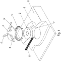
- a ring frame 3 is first aligned and held with an alignment unit.
- the alignment unit is supported on the edge of the hole,
- the alignment unit has a disk 4, on the upper side of which arms 5 each extend in the radial direction.
- the alignment unit is supported on the edge area of the bore, i.e. on the floor 1 or on the floor covering 8 applied to the floor 1.
- the thickness of the floor covering can be taken into account by means of the adjusting screws 20, so that the arms 5 are arranged at the intended height above the floor. This is because the floor covering can also be applied subsequently in the edge region of the borehole if it was not initially present or was destroyed and/or at least partially removed as a result of the production of the stepped borehole.
- the disk 4 held by the arms 5 can be arranged in the intended position.
- the stepped bore introduced into the base 1 has a step 7 , an empty pipe 6 laid in the base 1 opening into the region of the stepped bore located below the step 7 .
- a sealing body 2 is introduced into the lower region of the stepped bore, which in the axial direction, ie in the direction of the bore axis of the stepped bore, covers the region axially covered by the mouth region.
- the sealing body 2 extends axially into the area covered axially by the ring frame 3 .
- the gap area present between the step 7 and the ring frame 3 is covered and casting compound 30 can be filled into this gap area.
- the gap area extends radially between the base 1 and the annular frame 3 and axially up to the step 7.
- the annular frame 3 is spaced apart from the base 1, in particular from the wall of the stepped bore, both in the radial direction and in the axial direction.
- casting compound 30 can be filled into the gap surrounding the ring frame 3 .
- the penetration of the sealing compound 30 into the area of the stepped bore is prevented by the sealing body 2.
- the compensating means in particular the disc 4 with arms 5, can be removed.
- the annular frame 3 is thus held in a materially bonded manner by means of the casting compound 30 and is therefore connected to the floor 1 .
- the sealing body 2 has a centrally arranged, axially continuous hole, so that it can be easily removed from the region of the stepped bore with a finger.
- the sealing body 2 is made from a foam material, in particular plastic, and is in particular in the shape of a torus.
- the sealing body 2 is hollow and has a skin made of rubber or plastic forming the surface, whereby it can be inflated with compressed air and when inflated it nestles against the wall of the stepped bore lying axially below the step 7 of the stepped bore and also on the ring frame, limiting the gap 3 is present. After the casting compound 30 has been poured in, the air is then let out of the sealing body 2 .
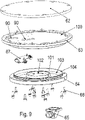
- figure 5 is one to run after Figures 1 to 4 alternative orientation of the ring frame 3 shown on the stepped bore.
- the ring frame 3 has axially directed threaded holes on its circumference, into which threaded pins 50 can be screwed, so that they enable the ring frame 3 to be supported on the step 7 of the stepped hole.
- the position of the ring frame 3 can be determined, in particular the height of the ring frame 3.
- the axially upper edge region of the ring frame 3 is the same as in the embodiment according to FIG Figure 1 to 4 brought to the height of the floor covering 8, so that at the latest after the repair or application of the floor covering 8 of the ring frame 3 is arranged in the intended height.
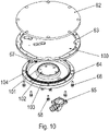
- a spiral rectangular winding 61 is accommodated in a corresponding spirally rectangular groove which is arranged on the underside of a cover part 62 .
- the cover part 62 acts as a winding carrier for the winding 61.
- the cover part 62 has a circular, ie circular-cylindrical outer circumference.
- the cover part 62 is connected to a receiving part 63 .
- a ferrite layer 60 is accommodated in the receiving part 63, which essentially fills a circular plate-like, ie circular-cylindrical spatial area, the ferrite layer preferably being composed of small, parallelepiped-shaped ferrite parts arranged next to one another.
- the ferrite layer 60 is therefore arranged between the cover part 62 and the receiving part 63 .
- the spatial area filled by the ferrite layer 60 is delimited by the cover part 62 and the receiving part 63 .
- the receiving part 63 is screw-connected to the frame part 3 by means of screws 69 passing through the cover part 62 and through the receiving part 63 . That points to this Frame part 3 corresponding to axially directed threaded holes, in which the screws 69 are at least partially screwed.
- the underside of the receiving part 63 ie the side of the receiving part 63 facing away from the cover part 62, is covered by a lower part 64, in particular a lower cover part.
- a lower part 64 in particular a lower cover part.
- an annular spatial area is formed between the receiving part 63 and the lower part 64, in which a printed circuit board 67 is arranged.
- the ring-shaped spatial area runs all the way around in the circumferential direction, that is to say without interruption in the circumferential direction.
- capacitors are fitted, which are connected to the winding 61 in parallel or in series.
- the resonant frequency of the resonant circuit created in this way corresponds to the frequency of the current injected into the winding by a feed device.
- the power is supplied from the feed device, which is not shown in the figures, via a line 66, i.e. a cable which is routed through the empty tube 6 and through a cable gland 65 to the printed circuit board 67.
- the housing of the cable gland 65 is on the underside of the lower part 64, ie arranged on the side of the lower part 64 facing away from the receiving part 63 .
- a controllable light source Arranged centrally between the receiving part 63 and the lower part 64 is another spatial area in which a controllable light source can be provided.
- the bore is preferably filled with a transparent substance.
- the light source can be controlled in such a way that the light source can be switched on or off and/or that the color of the light source can be controlled. In this way, different operating states or other information can be displayed.
- the winding 61 is designed as a flat ring winding.
- the ring winding is designed in the form of a circular spiral.
- the handset can be rotated on the charging point during the transfer of energy, without the inductive coupling between the winding 61 and the secondary winding, which is arranged on the mobile part and preferably also designed as a flat circular spiral-shaped ring winding, fluctuating.
- the time of changing the steering angle of a mobile part with a tank drive or other omnidirectional drive can be used for an inductive transmission of energy to the mobile part.
- the lower part 64 is screwed to the receiving part 63 by means of screws 68 .
- a seal 81 is arranged between the cover part 62 and the receiving part 63, which is arranged on a larger diameter than the ferrite layer 60 and than the winding 61.
- the seal 81 is preferably designed as an O-ring.
- a seal 80 is also arranged between the lower part 64 and the receiving part 63, which seals off the spatial area accommodating the printed circuit board 67 from the outside environment.
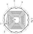
- the ferrite layer 60 is arranged in a recess 100 arranged on the receiving part 63 .
- This recess 100 is arranged on the upper side, ie on the side facing the cover part 62, of the receiving part 63.
- the receiving part 63 has two axially continuous recesses 90 spaced apart from one another, so that connection lines, such as the supply line 66, to the printed circuit board 67 can be passed through.
- the recesses 63 open into the depression 100 on the upper side of the receiving part 63.
- the lower part 64 has an annular wall 101 running around in the circumferential direction, which delimits the spatial area arranged centrally between the lower part 64 and the receiving part 63 .
- the lower part 64 has a further annular wall 104 running in the circumferential direction, which is radially spaced from the annular wall 101.
- the spatial area accommodating the printed circuit board 67 is therefore delimited by the annular wall 101 and the annular wall 104.
- the lower part 64 is screw-connected to the receiving part 63 by means of screws 68, the receiving part 63 having axially directed threaded bores for this purpose.
- the cover part 62 has on its side facing the receiving part 63, that is to say the underside, the groove 113 which runs in a rectangular spiral shape and into which the winding 61 is inserted.
- the winding wire ends of the winding 61 designed as a flat winding are led out to adapter circuit boards 111, on each of which an electrical connection part 112 is fitted. An electrical connection is thus provided in a simple manner.
- the adapter boards 111 ie printed circuit boards, are screw-connected and thus electrically connected to busbars 110, which are electrically connected to conductor tracks on the printed circuit board 67.
- the busbars 110 are arranged on the side of the ferrite layer facing away from the cover part 60 .
- the seal 81 can preferably be designed as a foam seal.
- the annular walls 101 and 104 formed on the lower part 64 are arranged on the side of the lower part 64 facing the receiving part 63 .
- the annular walls 101 and 104 touch the receiving part 63, so that the annular spatial area is formed radially between them, in which the printed circuit board 67 is arranged.
Landscapes
- Engineering & Computer Science (AREA)
- Power Engineering (AREA)
- Computer Networks & Wireless Communication (AREA)
- Transportation (AREA)
- Mechanical Engineering (AREA)
- Manufacturing & Machinery (AREA)
- Charge And Discharge Circuits For Batteries Or The Like (AREA)
- Casings For Electric Apparatus (AREA)
- Discharge Lamps And Accessories Thereof (AREA)
- Details Of Aerials (AREA)
Claims (3)
- Procédé de production d'un système dévolu à la transmission d'énergie, par induction, d'une partie primaire implantée au sol à une partie mobile apte à se mouvoir sur ledit sol,
caractérisé par le faitqu'un perçage étagé est pratiqué dans un sol (1) lors d'une première étape opératoire, sachant que, lors d'une deuxième étape opératoire successive, un corps d'étanchement (2) est inséré dans ledit perçage étagé,sachant que, lors d'une troisième étape opératoire successive, un cadre annulaire (3) est retenu dans ledit perçage étagé au moyen d'une unité d'alignement prenant appui à la surface du sol (1), sachant notamment que l'arête supérieure dudit cadre annulaire (3) est alignée avec la hauteur du sol (1) ou avec la surface d'un revêtement (8) mis en place sur ledit sol (1), c'est-à-dire, en particulier, que ladite arête supérieure est amenée à un même emplacement en hauteur que ladite surface du sol (1), ou du revêtement (8) dudit sol,ledit cadre annulaire (3) étant situé à distance du sol (1), de manière qu'une zone de clivage soit présente entre ledit cadre annulaire (3) et ledit sol (1),sachant que, lors d'une quatrième étape opératoire successive, de la masse de scellement (30) est déversée dans ladite zone de clivage,sachant que ladite unité d'alignement est enlevée lors d'une cinquième étape opératoire successive,sachant que, lors d'une sixième étape opératoire successive, une partie primaire est logée dans le cadre annulaire (3) en étant notamment reliée par vissage. - Procédé selon la revendication 1,
caractérisé par le fait que
le corps d'étanchement (2) est en applique, en particulier par pression, contre le perçage étagé et notamment au niveau d'une région du perçage étagé située au-dessous du gradin (7) dudit perçage étagé, et contre le cadre annulaire (3), en particulier contre la paroi intérieure dudit cadre annulaire (3). - Procédé selon au moins l'une des revendications précédentes,
caractérisé par le fait quela partie primaire est munie d'un bobinage (61),sachant notamment qu'une ligne (66) d'alimentation électrique, dédiée audit bobinage (61), est logée dans un tube vide (6) qui débouche dans la région située au-dessous du gradin (7) du perçage étagé ;et/ou par le fait quel'unité d'alignement est orientée au niveau de la surface du revêtement (8) du sol (1) ; et/ou par le fait quele cadre annulaire (3) est disposé au-dessus dudit gradin (7) du perçage étagé.
Applications Claiming Priority (2)
| Application Number | Priority Date | Filing Date | Title |
|---|---|---|---|
| DE102017003498 | 2017-04-07 | ||
| PCT/EP2018/025064 WO2018184730A1 (fr) | 2017-04-07 | 2018-03-20 | Procédé servant à fabriquer un système servant à transmettre par induction de l'énergie à une partie mobile et dispositif servant à mettre en œuvre le procédé |
Publications (2)
| Publication Number | Publication Date |
|---|---|
| EP3607635A1 EP3607635A1 (fr) | 2020-02-12 |
| EP3607635B1 true EP3607635B1 (fr) | 2022-10-19 |
Family
ID=61750070
Family Applications (1)
| Application Number | Title | Priority Date | Filing Date |
|---|---|---|---|
| EP18712504.2A Active EP3607635B1 (fr) | 2017-04-07 | 2018-03-20 | Procédé servant à fabriquer un système servant à transmettre par induction de l'énergie à une partie mobile et dispositif servant à mettre en oeuvre le procédé |
Country Status (5)
| Country | Link |
|---|---|
| US (2) | US11101692B2 (fr) |
| EP (1) | EP3607635B1 (fr) |
| CN (1) | CN110462973B (fr) |
| DE (1) | DE102018002275A1 (fr) |
| WO (1) | WO2018184730A1 (fr) |
Families Citing this family (7)
| Publication number | Priority date | Publication date | Assignee | Title |
|---|---|---|---|---|
| DE102016219476A1 (de) * | 2016-10-07 | 2018-04-12 | Bayerische Motoren Werke Aktiengesellschaft | Induktive Ladeeinheit für ein Fahrzeug |
| US11101692B2 (en) * | 2017-04-07 | 2021-08-24 | Sew-Eurodrive Gmbh & Co. Kg | Method for producing a system for inductively transmitting energy to a mobile part, and device for carrying out the method |
| DE102018007910A1 (de) * | 2017-10-20 | 2019-04-25 | Sew-Eurodrive Gmbh & Co Kg | System zur berührungslosen Übertragung von elektrischer Energie an ein auf einem Boden einer Anlage verfahrbares Mobilteil |
| WO2019086143A1 (fr) * | 2017-11-03 | 2019-05-09 | Sew-Eurodrive Gmbh & Co. Kg | Système de transmission sans contact d'énergie électrique à un élément mobile |
| US11063415B2 (en) * | 2019-01-16 | 2021-07-13 | Raymond & Lae Engineering, Inc. | Raised access floor panel with embedded sensors |
| WO2020164800A1 (fr) | 2019-02-13 | 2020-08-20 | Sew-Eurodrive Gmbh & Co. Kg | Système de transmission sans contact de puissance électrique à un élément mobile |
| US12283447B2 (en) * | 2020-02-18 | 2025-04-22 | Ujniversity of Manitoba | Direct current circuit breaker and related method |
Citations (1)
| Publication number | Priority date | Publication date | Assignee | Title |
|---|---|---|---|---|
| US20160308391A1 (en) * | 2015-04-15 | 2016-10-20 | Wireless Advanced Vehicle Electrification, Inc. | Removable inductive power transfer pad |
Family Cites Families (17)
| Publication number | Priority date | Publication date | Assignee | Title |
|---|---|---|---|---|
| DE3700488A1 (de) * | 1987-01-08 | 1988-07-21 | Klaus Dipl Ing Becker | Leistungsuebertrager mit ferromagnetischem kern |
| FR2775383B1 (fr) * | 1998-02-25 | 2000-05-05 | Siraga Sa | Transformateur tournant comportant un corps fixe et un corps rotatif disposes l'un en face de l'autre |
| DE102006025460B4 (de) | 2006-05-30 | 2022-01-20 | Sew-Eurodrive Gmbh & Co Kg | Anlage mit einem Primärleitersystem |
| WO2010062345A2 (fr) * | 2008-10-31 | 2010-06-03 | Lam Research Corporation | Ensemble d'électrode inférieure de chambre de traitement au plasma |
| US9873347B2 (en) | 2009-03-12 | 2018-01-23 | Wendell Brown | Method and apparatus for automatic charging of an electrically powered vehicle |
| JPWO2011154993A1 (ja) | 2010-06-08 | 2013-08-01 | 株式会社日立製作所 | 絶縁トランスおよび電源装置 |
| US9327608B2 (en) * | 2011-08-04 | 2016-05-03 | Schneider Electric USA, Inc. | Extendable and deformable carrier for a primary coil of a charging system |
| DE102012202472B4 (de) | 2012-02-17 | 2018-03-01 | Siemens Aktiengesellschaft | Vorrichtung zur kontaktlosen Übertragung von Energie auf eine korrespondierende Vorrichtung |
| DE102013007850B4 (de) * | 2013-05-08 | 2023-08-10 | Sew-Eurodrive Gmbh & Co Kg | Transformatoranordnung |
| DE102014000347B4 (de) * | 2014-01-16 | 2022-10-06 | Sew-Eurodrive Gmbh & Co Kg | Primärteil, insbesondere bodengebundenes Primärteil, für ein System zur berührungslosen Energieübertragung |
| US9794033B2 (en) * | 2014-03-14 | 2017-10-17 | Intel IP Corporation | Systems, methods and devices for opportunistic networking |
| US9583256B2 (en) | 2014-06-13 | 2017-02-28 | Verily Life Sciences Llc | Three-dimensional wireless charging coil |
| US9796272B2 (en) * | 2014-08-25 | 2017-10-24 | Bryan Richards | Road bearing for electric vehicle connection |
| US10622142B2 (en) * | 2016-09-26 | 2020-04-14 | Utah State University | Concrete-embedded wireless power transfer coil |
| JP6606047B2 (ja) * | 2016-10-03 | 2019-11-13 | 株式会社東芝 | 送電装置 |
| CN108538744B (zh) * | 2017-03-01 | 2021-03-02 | 北京北方华创微电子装备有限公司 | 卡盘装置以及半导体加工设备 |
| US11101692B2 (en) * | 2017-04-07 | 2021-08-24 | Sew-Eurodrive Gmbh & Co. Kg | Method for producing a system for inductively transmitting energy to a mobile part, and device for carrying out the method |
-
2018
- 2018-03-20 US US16/603,505 patent/US11101692B2/en active Active
- 2018-03-20 CN CN201880021690.5A patent/CN110462973B/zh active Active
- 2018-03-20 DE DE102018002275.8A patent/DE102018002275A1/de active Pending
- 2018-03-20 EP EP18712504.2A patent/EP3607635B1/fr active Active
- 2018-03-20 WO PCT/EP2018/025064 patent/WO2018184730A1/fr not_active Ceased
-
2021
- 2021-08-10 US US17/398,049 patent/US11594914B2/en active Active
Patent Citations (1)
| Publication number | Priority date | Publication date | Assignee | Title |
|---|---|---|---|---|
| US20160308391A1 (en) * | 2015-04-15 | 2016-10-20 | Wireless Advanced Vehicle Electrification, Inc. | Removable inductive power transfer pad |
Also Published As
| Publication number | Publication date |
|---|---|
| US11101692B2 (en) | 2021-08-24 |
| WO2018184730A1 (fr) | 2018-10-11 |
| US11594914B2 (en) | 2023-02-28 |
| CN110462973B (zh) | 2023-06-27 |
| EP3607635A1 (fr) | 2020-02-12 |
| CN110462973A (zh) | 2019-11-15 |
| US20210091596A1 (en) | 2021-03-25 |
| US20210367449A1 (en) | 2021-11-25 |
| DE102018002275A1 (de) | 2018-10-11 |
Similar Documents
| Publication | Publication Date | Title |
|---|---|---|
| EP3607635B1 (fr) | Procédé servant à fabriquer un système servant à transmettre par induction de l'énergie à une partie mobile et dispositif servant à mettre en oeuvre le procédé | |
| EP2871149A1 (fr) | Entraînement d'une coulisse d'un système de verrouillage d'un système de télescopage d'une flèche de grue | |
| EP3066372B1 (fr) | Dispositif de commande de soupape et soupape de processus | |
| WO2012123040A1 (fr) | Dispositif de transmission d'énergie électrique et/ou de signaux électriques d'une paroi fixe à un vantail fixé à la paroi | |
| EP1640543B1 (fr) | Dispositif de propulsion pour un élément de séparation coulissant | |
| EP2792604B1 (fr) | Machine de traitement de récipient | |
| EP0663556A1 (fr) | Jonction rotative | |
| EP0709610B1 (fr) | Raccord de tuyau | |
| DE102013003506A1 (de) | System zur induktiven Übertragung elektrischer Energie an ein Fahrzeug | |
| DE102005013853A1 (de) | Magnetresonanzanlage | |
| DE3816884C2 (fr) | ||
| DE102018201160A1 (de) | Hochspannungsdurchführung, elektrisches Gerät mit Hochspannungsdurchführung und Verfahren zur Herstellung des elektrischen Gerätes | |
| DE1750392A1 (de) | Vorrichtung zum Anschluss einer elektrischen Leitung an einen Schlauch | |
| EP2422946B1 (fr) | Dispositif de transmission pour rayonnement | |
| DE102014114640A1 (de) | Induktives Energieübertragungssystem mit breiter Primäranordnung | |
| EP2329896A1 (fr) | Dispositif d'enroulement continu d'un tuyau métallique | |
| DE19530163C2 (de) | Hochspannungsausleitungs- und -durchführungsanordnung für Transformatoren oder Drosselspulen | |
| DE2554460B2 (de) | Transformator für hohe Spannung mit einer örtlich verformbaren Verbindung zwischen einer Wicklung und einem Anschlußleiter | |
| EP1926921A1 (fr) | Frein a disque pour vehicule utilitaire | |
| EP2907717A2 (fr) | Dispositif de serrage amovible en fonctionnement | |
| EP1287952A1 (fr) | Connection tournante placée au bout d'un bras de robot | |
| WO2012025597A2 (fr) | Système de transfert pour charger les batteries de traction d'un véhicule automobile électrique et élément transformateur pour ce système de transfert | |
| EP3698453B1 (fr) | Système de transmission sans contact d'énergie électrique à une partie mobile pouvant être déplacée sur un plancher d'un équipement | |
| DE102006009167B4 (de) | Drehverbinder | |
| WO2008011907A1 (fr) | Dispositif de soudage pour soudage à l'arc avec amorçage par arc tiré |
Legal Events
| Date | Code | Title | Description |
|---|---|---|---|
| STAA | Information on the status of an ep patent application or granted ep patent |
Free format text: STATUS: UNKNOWN |
|
| STAA | Information on the status of an ep patent application or granted ep patent |
Free format text: STATUS: THE INTERNATIONAL PUBLICATION HAS BEEN MADE |
|
| PUAI | Public reference made under article 153(3) epc to a published international application that has entered the european phase |
Free format text: ORIGINAL CODE: 0009012 |
|
| STAA | Information on the status of an ep patent application or granted ep patent |
Free format text: STATUS: REQUEST FOR EXAMINATION WAS MADE |
|
| 17P | Request for examination filed |
Effective date: 20191107 |
|
| AK | Designated contracting states |
Kind code of ref document: A1 Designated state(s): AL AT BE BG CH CY CZ DE DK EE ES FI FR GB GR HR HU IE IS IT LI LT LU LV MC MK MT NL NO PL PT RO RS SE SI SK SM TR |
|
| AX | Request for extension of the european patent |
Extension state: BA ME |
|
| DAV | Request for validation of the european patent (deleted) | ||
| DAX | Request for extension of the european patent (deleted) | ||
| STAA | Information on the status of an ep patent application or granted ep patent |
Free format text: STATUS: EXAMINATION IS IN PROGRESS |
|
| 17Q | First examination report despatched |
Effective date: 20200917 |
|
| GRAP | Despatch of communication of intention to grant a patent |
Free format text: ORIGINAL CODE: EPIDOSNIGR1 |
|
| STAA | Information on the status of an ep patent application or granted ep patent |
Free format text: STATUS: GRANT OF PATENT IS INTENDED |
|
| INTG | Intention to grant announced |
Effective date: 20220602 |
|
| GRAS | Grant fee paid |
Free format text: ORIGINAL CODE: EPIDOSNIGR3 |
|
| GRAA | (expected) grant |
Free format text: ORIGINAL CODE: 0009210 |
|
| STAA | Information on the status of an ep patent application or granted ep patent |
Free format text: STATUS: THE PATENT HAS BEEN GRANTED |
|
| AK | Designated contracting states |
Kind code of ref document: B1 Designated state(s): AL AT BE BG CH CY CZ DE DK EE ES FI FR GB GR HR HU IE IS IT LI LT LU LV MC MK MT NL NO PL PT RO RS SE SI SK SM TR |
|
| REG | Reference to a national code |
Ref country code: GB Ref legal event code: FG4D Free format text: NOT ENGLISH |
|
| REG | Reference to a national code |
Ref country code: CH Ref legal event code: EP |
|
| REG | Reference to a national code |
Ref country code: IE Ref legal event code: FG4D Free format text: LANGUAGE OF EP DOCUMENT: GERMAN |
|
| REG | Reference to a national code |
Ref country code: DE Ref legal event code: R096 Ref document number: 502018010863 Country of ref document: DE |
|
| REG | Reference to a national code |
Ref country code: AT Ref legal event code: REF Ref document number: 1526177 Country of ref document: AT Kind code of ref document: T Effective date: 20221115 |
|
| REG | Reference to a national code |
Ref country code: LT Ref legal event code: MG9D |
|
| REG | Reference to a national code |
Ref country code: NL Ref legal event code: MP Effective date: 20221019 |
|
| PG25 | Lapsed in a contracting state [announced via postgrant information from national office to epo] |
Ref country code: NL Free format text: LAPSE BECAUSE OF FAILURE TO SUBMIT A TRANSLATION OF THE DESCRIPTION OR TO PAY THE FEE WITHIN THE PRESCRIBED TIME-LIMIT Effective date: 20221019 |
|
| PG25 | Lapsed in a contracting state [announced via postgrant information from national office to epo] |
Ref country code: SE Free format text: LAPSE BECAUSE OF FAILURE TO SUBMIT A TRANSLATION OF THE DESCRIPTION OR TO PAY THE FEE WITHIN THE PRESCRIBED TIME-LIMIT Effective date: 20221019 Ref country code: PT Free format text: LAPSE BECAUSE OF FAILURE TO SUBMIT A TRANSLATION OF THE DESCRIPTION OR TO PAY THE FEE WITHIN THE PRESCRIBED TIME-LIMIT Effective date: 20230220 Ref country code: NO Free format text: LAPSE BECAUSE OF FAILURE TO SUBMIT A TRANSLATION OF THE DESCRIPTION OR TO PAY THE FEE WITHIN THE PRESCRIBED TIME-LIMIT Effective date: 20230119 Ref country code: LT Free format text: LAPSE BECAUSE OF FAILURE TO SUBMIT A TRANSLATION OF THE DESCRIPTION OR TO PAY THE FEE WITHIN THE PRESCRIBED TIME-LIMIT Effective date: 20221019 Ref country code: FI Free format text: LAPSE BECAUSE OF FAILURE TO SUBMIT A TRANSLATION OF THE DESCRIPTION OR TO PAY THE FEE WITHIN THE PRESCRIBED TIME-LIMIT Effective date: 20221019 Ref country code: ES Free format text: LAPSE BECAUSE OF FAILURE TO SUBMIT A TRANSLATION OF THE DESCRIPTION OR TO PAY THE FEE WITHIN THE PRESCRIBED TIME-LIMIT Effective date: 20221019 |
|
| PG25 | Lapsed in a contracting state [announced via postgrant information from national office to epo] |
Ref country code: RS Free format text: LAPSE BECAUSE OF FAILURE TO SUBMIT A TRANSLATION OF THE DESCRIPTION OR TO PAY THE FEE WITHIN THE PRESCRIBED TIME-LIMIT Effective date: 20221019 Ref country code: PL Free format text: LAPSE BECAUSE OF FAILURE TO SUBMIT A TRANSLATION OF THE DESCRIPTION OR TO PAY THE FEE WITHIN THE PRESCRIBED TIME-LIMIT Effective date: 20221019 Ref country code: LV Free format text: LAPSE BECAUSE OF FAILURE TO SUBMIT A TRANSLATION OF THE DESCRIPTION OR TO PAY THE FEE WITHIN THE PRESCRIBED TIME-LIMIT Effective date: 20221019 Ref country code: IS Free format text: LAPSE BECAUSE OF FAILURE TO SUBMIT A TRANSLATION OF THE DESCRIPTION OR TO PAY THE FEE WITHIN THE PRESCRIBED TIME-LIMIT Effective date: 20230219 Ref country code: HR Free format text: LAPSE BECAUSE OF FAILURE TO SUBMIT A TRANSLATION OF THE DESCRIPTION OR TO PAY THE FEE WITHIN THE PRESCRIBED TIME-LIMIT Effective date: 20221019 Ref country code: GR Free format text: LAPSE BECAUSE OF FAILURE TO SUBMIT A TRANSLATION OF THE DESCRIPTION OR TO PAY THE FEE WITHIN THE PRESCRIBED TIME-LIMIT Effective date: 20230120 |
|
| REG | Reference to a national code |
Ref country code: DE Ref legal event code: R097 Ref document number: 502018010863 Country of ref document: DE |
|
| PG25 | Lapsed in a contracting state [announced via postgrant information from national office to epo] |
Ref country code: SM Free format text: LAPSE BECAUSE OF FAILURE TO SUBMIT A TRANSLATION OF THE DESCRIPTION OR TO PAY THE FEE WITHIN THE PRESCRIBED TIME-LIMIT Effective date: 20221019 Ref country code: RO Free format text: LAPSE BECAUSE OF FAILURE TO SUBMIT A TRANSLATION OF THE DESCRIPTION OR TO PAY THE FEE WITHIN THE PRESCRIBED TIME-LIMIT Effective date: 20221019 Ref country code: EE Free format text: LAPSE BECAUSE OF FAILURE TO SUBMIT A TRANSLATION OF THE DESCRIPTION OR TO PAY THE FEE WITHIN THE PRESCRIBED TIME-LIMIT Effective date: 20221019 Ref country code: DK Free format text: LAPSE BECAUSE OF FAILURE TO SUBMIT A TRANSLATION OF THE DESCRIPTION OR TO PAY THE FEE WITHIN THE PRESCRIBED TIME-LIMIT Effective date: 20221019 Ref country code: CZ Free format text: LAPSE BECAUSE OF FAILURE TO SUBMIT A TRANSLATION OF THE DESCRIPTION OR TO PAY THE FEE WITHIN THE PRESCRIBED TIME-LIMIT Effective date: 20221019 |
|
| PLBE | No opposition filed within time limit |
Free format text: ORIGINAL CODE: 0009261 |
|
| STAA | Information on the status of an ep patent application or granted ep patent |
Free format text: STATUS: NO OPPOSITION FILED WITHIN TIME LIMIT |
|
| PG25 | Lapsed in a contracting state [announced via postgrant information from national office to epo] |
Ref country code: SK Free format text: LAPSE BECAUSE OF FAILURE TO SUBMIT A TRANSLATION OF THE DESCRIPTION OR TO PAY THE FEE WITHIN THE PRESCRIBED TIME-LIMIT Effective date: 20221019 Ref country code: AL Free format text: LAPSE BECAUSE OF FAILURE TO SUBMIT A TRANSLATION OF THE DESCRIPTION OR TO PAY THE FEE WITHIN THE PRESCRIBED TIME-LIMIT Effective date: 20221019 |
|
| 26N | No opposition filed |
Effective date: 20230720 |
|
| PG25 | Lapsed in a contracting state [announced via postgrant information from national office to epo] |
Ref country code: MC Free format text: LAPSE BECAUSE OF FAILURE TO SUBMIT A TRANSLATION OF THE DESCRIPTION OR TO PAY THE FEE WITHIN THE PRESCRIBED TIME-LIMIT Effective date: 20221019 |
|
| REG | Reference to a national code |
Ref country code: CH Ref legal event code: PL |
|
| GBPC | Gb: european patent ceased through non-payment of renewal fee |
Effective date: 20230320 |
|
| PG25 | Lapsed in a contracting state [announced via postgrant information from national office to epo] |
Ref country code: SI Free format text: LAPSE BECAUSE OF FAILURE TO SUBMIT A TRANSLATION OF THE DESCRIPTION OR TO PAY THE FEE WITHIN THE PRESCRIBED TIME-LIMIT Effective date: 20221019 |
|
| REG | Reference to a national code |
Ref country code: BE Ref legal event code: MM Effective date: 20230331 |
|
| PG25 | Lapsed in a contracting state [announced via postgrant information from national office to epo] |
Ref country code: LU Free format text: LAPSE BECAUSE OF NON-PAYMENT OF DUE FEES Effective date: 20230320 |
|
| REG | Reference to a national code |
Ref country code: IE Ref legal event code: MM4A |
|
| PG25 | Lapsed in a contracting state [announced via postgrant information from national office to epo] |
Ref country code: GB Free format text: LAPSE BECAUSE OF NON-PAYMENT OF DUE FEES Effective date: 20230320 |
|
| PG25 | Lapsed in a contracting state [announced via postgrant information from national office to epo] |
Ref country code: LI Free format text: LAPSE BECAUSE OF NON-PAYMENT OF DUE FEES Effective date: 20230331 Ref country code: IE Free format text: LAPSE BECAUSE OF NON-PAYMENT OF DUE FEES Effective date: 20230320 Ref country code: GB Free format text: LAPSE BECAUSE OF NON-PAYMENT OF DUE FEES Effective date: 20230320 Ref country code: FR Free format text: LAPSE BECAUSE OF NON-PAYMENT OF DUE FEES Effective date: 20230331 Ref country code: CH Free format text: LAPSE BECAUSE OF NON-PAYMENT OF DUE FEES Effective date: 20230331 |
|
| PG25 | Lapsed in a contracting state [announced via postgrant information from national office to epo] |
Ref country code: BE Free format text: LAPSE BECAUSE OF NON-PAYMENT OF DUE FEES Effective date: 20230331 |
|
| REG | Reference to a national code |
Ref country code: AT Ref legal event code: MM01 Ref document number: 1526177 Country of ref document: AT Kind code of ref document: T Effective date: 20230320 |
|
| PG25 | Lapsed in a contracting state [announced via postgrant information from national office to epo] |
Ref country code: IT Free format text: LAPSE BECAUSE OF FAILURE TO SUBMIT A TRANSLATION OF THE DESCRIPTION OR TO PAY THE FEE WITHIN THE PRESCRIBED TIME-LIMIT Effective date: 20221019 |
|
| PG25 | Lapsed in a contracting state [announced via postgrant information from national office to epo] |
Ref country code: AT Free format text: LAPSE BECAUSE OF NON-PAYMENT OF DUE FEES Effective date: 20230320 |
|
| PG25 | Lapsed in a contracting state [announced via postgrant information from national office to epo] |
Ref country code: AT Free format text: LAPSE BECAUSE OF NON-PAYMENT OF DUE FEES Effective date: 20230320 |
|
| PG25 | Lapsed in a contracting state [announced via postgrant information from national office to epo] |
Ref country code: BG Free format text: LAPSE BECAUSE OF FAILURE TO SUBMIT A TRANSLATION OF THE DESCRIPTION OR TO PAY THE FEE WITHIN THE PRESCRIBED TIME-LIMIT Effective date: 20221019 |
|
| PG25 | Lapsed in a contracting state [announced via postgrant information from national office to epo] |
Ref country code: BG Free format text: LAPSE BECAUSE OF FAILURE TO SUBMIT A TRANSLATION OF THE DESCRIPTION OR TO PAY THE FEE WITHIN THE PRESCRIBED TIME-LIMIT Effective date: 20221019 |
|
| PGFP | Annual fee paid to national office [announced via postgrant information from national office to epo] |
Ref country code: DE Payment date: 20250331 Year of fee payment: 8 |
|
| PG25 | Lapsed in a contracting state [announced via postgrant information from national office to epo] |
Ref country code: CY Free format text: LAPSE BECAUSE OF FAILURE TO SUBMIT A TRANSLATION OF THE DESCRIPTION OR TO PAY THE FEE WITHIN THE PRESCRIBED TIME-LIMIT; INVALID AB INITIO Effective date: 20180320 |
|
| PG25 | Lapsed in a contracting state [announced via postgrant information from national office to epo] |
Ref country code: HU Free format text: LAPSE BECAUSE OF FAILURE TO SUBMIT A TRANSLATION OF THE DESCRIPTION OR TO PAY THE FEE WITHIN THE PRESCRIBED TIME-LIMIT; INVALID AB INITIO Effective date: 20180320 |
|
| PG25 | Lapsed in a contracting state [announced via postgrant information from national office to epo] |
Ref country code: TR Free format text: LAPSE BECAUSE OF FAILURE TO SUBMIT A TRANSLATION OF THE DESCRIPTION OR TO PAY THE FEE WITHIN THE PRESCRIBED TIME-LIMIT Effective date: 20221019 |