EP3605486B1 - Markerdetektionssystem und markierungsdetektionsverfahren - Google Patents
Markerdetektionssystem und markierungsdetektionsverfahren Download PDFInfo
- Publication number
- EP3605486B1 EP3605486B1 EP18777587.9A EP18777587A EP3605486B1 EP 3605486 B1 EP3605486 B1 EP 3605486B1 EP 18777587 A EP18777587 A EP 18777587A EP 3605486 B1 EP3605486 B1 EP 3605486B1
- Authority
- EP
- European Patent Office
- Prior art keywords
- magnetic
- marker
- magnetism generation
- detection
- markers
- Prior art date
- Legal status (The legal status is an assumption and is not a legal conclusion. Google has not performed a legal analysis and makes no representation as to the accuracy of the status listed.)
- Active
Links
Images


Classifications
-
- G—PHYSICS
- G05—CONTROLLING; REGULATING
- G05D—SYSTEMS FOR CONTROLLING OR REGULATING NON-ELECTRIC VARIABLES
- G05D1/00—Control of position, course, altitude or attitude of land, water, air or space vehicles, e.g. using automatic pilots
- G05D1/02—Control of position or course in two dimensions
- G05D1/021—Control of position or course in two dimensions specially adapted to land vehicles
- G05D1/0259—Control of position or course in two dimensions specially adapted to land vehicles using magnetic or electromagnetic means
- G05D1/0261—Control of position or course in two dimensions specially adapted to land vehicles using magnetic or electromagnetic means using magnetic plots
-
- G—PHYSICS
- G01—MEASURING; TESTING
- G01V—GEOPHYSICS; GRAVITATIONAL MEASUREMENTS; DETECTING MASSES OR OBJECTS; TAGS
- G01V3/00—Electric or magnetic prospecting or detecting; Measuring magnetic field characteristics of the earth, e.g. declination, deviation
- G01V3/08—Electric or magnetic prospecting or detecting; Measuring magnetic field characteristics of the earth, e.g. declination, deviation operating with magnetic or electric fields produced or modified by objects or geological structures or by detecting devices
- G01V3/081—Electric or magnetic prospecting or detecting; Measuring magnetic field characteristics of the earth, e.g. declination, deviation operating with magnetic or electric fields produced or modified by objects or geological structures or by detecting devices the magnetic field is produced by the objects or geological structures
-
- G—PHYSICS
- G05—CONTROLLING; REGULATING
- G05D—SYSTEMS FOR CONTROLLING OR REGULATING NON-ELECTRIC VARIABLES
- G05D1/00—Control of position, course, altitude or attitude of land, water, air or space vehicles, e.g. using automatic pilots
- G05D1/02—Control of position or course in two dimensions
- G05D1/021—Control of position or course in two dimensions specially adapted to land vehicles
- G05D1/0259—Control of position or course in two dimensions specially adapted to land vehicles using magnetic or electromagnetic means
-
- G—PHYSICS
- G08—SIGNALLING
- G08G—TRAFFIC CONTROL SYSTEMS
- G08G1/00—Traffic control systems for road vehicles
- G08G1/09—Arrangements for giving variable traffic instructions
- G08G1/0962—Arrangements for giving variable traffic instructions having an indicator mounted inside the vehicle, e.g. giving voice messages
- G08G1/09623—Systems involving the acquisition of information from passive traffic signs by means mounted on the vehicle
-
- G—PHYSICS
- G08—SIGNALLING
- G08G—TRAFFIC CONTROL SYSTEMS
- G08G1/00—Traffic control systems for road vehicles
- G08G1/16—Anti-collision systems
- G08G1/167—Driving aids for lane monitoring, lane changing, e.g. blind spot detection
Definitions
- the present invention relates to a marker detection system and marker detection method for detecting magnetic markers laid in a road.
- US 5 951 610 A discloses a motor vehicle which is automatically steered to run along a running path on a road while detecting magnetic nails that are arranged on the road at spaced intervals along the running path.
- the motor vehicle has a pair of magnetic nail sensors on respective front and rear portions thereof for detecting lateral deviations of magnetic nails with respect to the motor vehicle at the respective front and rear portions thereof.
- the magnetic nail sensors are spaced from each other by a distance which is substantially an integral multiple of the interval between adjacent two of the magnetic nails.
- An azimuth deviation or a lateral deviation of the motor vehicle with respect to the running path is calculated based on lateral deviations of the magnetic nails which are detected substantially simultaneously by the magnetic nail sensors, respectively.
- US 6 035 248 A discloses a road for guiding an automatically driven vehicle comprising a train of N-polarity magnetic nails arranged along a main path, and a train of S-polarity magnetic nails arranged on a branching path.
- An automatically driven motor vehicle including magnetic sensors, runs and is automatically steered by detecting the magnetic nails.
- Patent Literature 1 Japanese Unexamined Patent Application Publication No. 2005-202478
- the above-described conventional marker detection system has the following problem. That is, there is a problem in which reliability of magnetic marker detection may be impaired due to various external disturbances of magnetism acting on the magnetic sensors or the like. For example, a vehicle traveling alongside and an oncoming vehicle passing by can become a generation source of external disturbance of magnetism.
- the present invention was made in view of the above-described conventional problem, and is to provide a marker detection system and marker detection method capable of reducing erroneous detection.
- the present invention provides a marker detection system according to claim 1, and a marker detection method according to claim 5. Further embodiments of the present invention are disclosed in the dependent claims.
- the marker detection system is a system including at least two magnetic markers arranged at spacings equal to spacings of said at least two magnetic detection units on a vehicle side. And, the marker detection method according to the present invention detects magnetism generation sources simultaneously detected by said at least two magnetic detection units as the magnetic markers.
- a magnetism generation source resulting from a magnetized fallen object a magnetism generation source such as a manhole, or the like is present on a road surface
- a condition for detection as the magnetic markers if a condition is set that they are magnetism generation sources simultaneously detected by said at least two magnetic detection units, the possibility of erroneously detecting a magnetism generation source such as, for example, a fallen object or manhole, as the magnetic marker can be reduced.
- the marker detection system and the marker detection method according to the present invention are a system or method with an excellent characteristic capable of reducing erroneous detection.
- said at least two magnetic markers are preferably arranged so that magnetic polarities form a predetermined pattern.
- the magnetism generation sources simultaneously detected by said at least two magnetic detection units are preferably detected as the magnetic markers.
- erroneous detection of a magnetism generation source other than the magnetic markers can be effectively reduced.
- a magnetism generation source exceeding the full length of the vehicle such as a large iron plate laid on a road surface during road construction or a steel frame of a bridge
- a marker detection system of one suitable aspect in the present invention includes another magnetic detection unit which can detect the magnetic markers but is different from the said at least two magnetic detection units, and the other magnetic detection unit is attached to the vehicle so as not to detect the magnetic markers when said at least two magnetic detection units simultaneously detect said at least two magnetic markers.
- the magnetism generation sources simultaneously detected by said at least two magnetic detection units are preferably detected as the magnetic markers.
- the respective magnetic markers including said at least two magnetic markers are preferably arranged at substantially constant spacings in a road direction.
- the present embodiment is an example regarding a marker detection system 1 for detecting magnetic markers 10 laid in a road and a marker detection method. Details of this are described by using FIG. 1 to FIG. 10 .
- the marker detection system 1 of the present embodiment is a system as in FIG. 1 for detecting the magnetic markers 10 laid in the road by sensor units 11, which are one example of magnetic detection units, attached to a vehicle 5.
- This marker detection system 1 is configured to include two sensor units 11 arranged so as to be separated in a longitudinal direction of the vehicle 5 and two magnetic markers 10 as many as these two sensor units 11 and arranged at spacing equal thereto so as to be simultaneously detectable by these two sensor units 11.
- the magnetic marker 10 is described, and then description is made on the sensor unit 11 including magnetic censors Cn ( FIG. 3 ) and a detection unit 12 which determines whether a magnetism generation source is the magnetic marker 10.
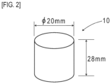
- the magnetic marker 10 is a marker laid in a road surface 100S of a road where the vehicle 5 travels, as in FIG. 1 and FIG. 2 .
- the magnetic markers 10 are arranged at spacings of 2 m along the center of a lane, which indicates a traveling segment of the road. In the following, the spacings of 2 m of the magnetic markers 10 are referred to as a marker span M.
- the magnetic marker 10 forms a columnar shape having a diameter of 20 mm and a height of 28 mm, and is laid as being accommodated in a hole provided in the road surface 100S.
- This magnetic marker 10 can act magnetism of a magnetic flux density of 8 ⁇ T (microtesla) at a height of 250 mm, which is an upper limit of a range from 100 to 250 mm assumed as an attachment height of the sensor units 11. Note that a magnetic flux density Gs of the surface of the magnet forming the magnetic marker 10 is 45 mT.
- the sensor units 11 are magnetic detection units to be attached to the bottom surface of the vehicle 5, as in FIG. 1 and FIG. 3 .
- the sensor units 11 are arranged at two locations at a spacing of 2 m (sensor span S) in the longitudinal direction of the vehicle 5.
- the front-side sensor unit 11 is attached to the rear side of a front axle, and the rear-side sensor unit 11 is attached to the front side of a rear axle.
- each attachment height with reference to the road surface 100S is 200 mm.
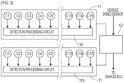
- Each sensor unit 11 includes fifteen magnetic sensors Cn (n is an integer of 1 to 15) arrayed on a straight line along a vehicle-width direction and a detection processing circuit 110 having a CPU and so forth not depicted incorporated therein ( FIG. 3 ).
- the magnetic sensors Cn adopted in the present embodiment are MI sensors which detect magnetism by using the known MI effect (Magneto Impedance Effect) in which the impedance of a magneto-sensitive body such as an amorphous wire sensitively changes in response to the external magnetic field.
- the magnetic sensors Cn are incorporated in the sensor unit 11 so that the magneto-sensitive bodies are along the vertical direction so as to detect magnetism in the vertical direction.
- the detection unit 12 is a unit which controls the front-side and rear-side sensor units 11 and outputs the result of detection of any magnetic marker 10, as in FIG. 1 and FIG. 3 .
- the detection unit 12 includes an electronic substrate (not depicted) having a CPU which performs various computations as well as memory elements such as a ROM and RAM and so forth implemented thereon.
- a vehicle ECU To this detection unit 12, in addition to the front-side and rear-side sensor units 11, a vehicle ECU, a vehicle speed sensor for measuring a speed of the vehicle, and so forth are electrically connected.
- This detection unit 12 takes in the magnetic detection result of each sensor unit 11, and generates and outputs a marker detection result which is a determination result as to whether the magnetic marker 10 has been detected or the like.
- the marker detection result is inputted to the vehicle ECU not depicted to be used in various controls on the vehicle side, such as automatic steering control, lane departure warning, and automatic driving for keeping the lane.
- the detection unit 12 uses the magnetic detection results of the front-side sensor unit 11 and the rear-side sensor unit 11 to perform a marker detection process for magnetic marker detection and so forth. Then, the marker detection result is generated, which is a determination result or the like as to whether the magnetic marker 10 has been detected, and is inputted to the vehicle ECU.
- the front-side and rear-side sensor units 11 perform a magnetic detection process at a frequency of 3 kHz by control of the detection unit 12. For every execution period (p1 to p7) of the magnetic detection process, each sensor unit 11 samples a magnetic measurement value indicated by a sensor signal of each of fifteen magnetic sensors Cn to acquire a magnetic distribution in the vehicle-width direction (refer to FIG. 4 ). A peak value in this magnetic distribution in the vehicle-width direction becomes maximum at the time of passage over a magnetism generation source such as the magnetic marker 10 (period p4 in FIG. 4 ) .
- the peak value of the magnetic distribution in the vehicle-width direction appears at every passage over the magnetic marker 10 as in FIG. 5 .
- the sensor unit 11 makes a threshold determination regarding this peak value and, when it is equal to or larger than a predetermined threshold, determines that a magnetism generation source that is likely to be the magnetic marker 10 has been detected.
- the sensor unit 11 detects a magnetism generation source, it is identified which magnetic measurement value of any of the magnetic sensors Cn is a peak value. Then, a positional shift amount of the peak value in the vehicle-width direction of the magnetic sensor Cn from the center position of the sensor unit 11 is identified, and is measured as a lateral shift amount of the vehicle 5 with respect to the magnetic marker 10.
- the detection unit 12 controls the front-side sensor unit 11 and the rear-side sensor unit 11 to acquire each magnetic detection result. Then, based on a combination of the acquired two magnetic detection results, the detection unit 12 performs a marker detection process for detecting the magnetic marker 10.
- the detection unit 12 determines that each magnetism generation source is the magnetic marker 10.
- the magnetic marker 10 As exemplarily depicted in FIG. 6 , when the front-side and rear-side sensor units 11 each reach straight above the magnetic marker 10, as exemplarily depicted in graphs in the drawing each illustrating temporal changes of the magnetic measurement value, the magnetic measurement values of the respective sensor units 11 simultaneously become peak values. When the magnetic measurement values of the respective sensor units 11 simultaneously become peak values, the detection unit 12 determines that each magnetism generation source is the magnetic marker 10.
- simultaneity of detection time of magnetism generation sources by the front-side and rear-side sensor units 11 does not mean strictly physical simultaneity.
- the front-side and rear-side sensor units 11 do not detect the same magnetism generation source.
- the front-side and rear-side sensor units 11 each detect a magnetism generation source in this temporal range.
- the detection unit 12 sets a temporal range required for the vehicle to travel 0.5 m as a detection period. If a detection time (second time) of the other sensor unit 11 which detects a magnetism generation source is included in this detection period, it can be regarded that the front-side and rear-side sensor units 11 simultaneously detected magnetism generation sources. In this case, the detection unit 12 determines each of the magnetism generation sources simultaneously detected by the front-side and rear-side sensor units 11 as the magnetic marker 10. Note that the time of momentarily in advance detecting a magnetism generation source means a detection time strictly earlier in time between detection times treated by the detection unit 12 as simultaneous as described above.
- the detection unit 12 On determining that the magnetism generation sources detected by each sensor unit 11 are the magnetic markers 10, the detection unit 12 inputs the marker detection result that the magnetic marker 10 has been detected to the vehicle ECU. Note that, at this time, the detection unit 12 simultaneously inputs the lateral shift amount measured by each sensor unit 11 as described above.
- the vehicle ECU acquiring the lateral shift amounts as well as the indication that the magnetic markers 10 have been detected can perform driving assist control such as lane following control by using the lateral shift amounts as control inputs.
- the detection unit 12 determines that the magnetism generation source detected by said either of the sensor units 11 is not the magnetic marker 10 and there is a possibility of erroneous detection.
- This situation can occur when, for example, as in FIG. 7 , either of the sensor units 11 detects magnetism of a magnetism generation source 10F other than the magnetic marker 10. In this case, while the magnetic measurement value of the rear-side sensor unit 11 becomes a peak value, the magnetic measurement value of the front-side sensor unit 11 remains low.
- the detection unit 12 determines that magnetism detected by the rear-side sensor unit 11 derives from the magnetism generation source 10F other than the magnetic marker 10.
- the marker span M on a road side and a sensor span S on a vehicle side match each other. If this configuration is adopted, when the front-side and rear-side sensor units 11 simultaneously detect magnetism generation sources, these magnetism generation sources can be determined as the magnetic markers 10.
- either one of the sensor units 11 detects a magnetism generation source while the other sensor unit 11 does not detect a magnetism generation source, it can be determined that the possibility is high that the detected magnetism generation source is not the magnetic marker 10. According to this determination, it can be determined that the possibility is high that the magnetism generation source such as a fallen object or manhole is not a magnetic marker, and erroneous detection can be avoided.
- the present embodiment is an example in which the magnetic markers 10 are arranged in the road at constant spacings (marker span M).
- two magnetic markers 10 separated with the marker span M may be laid in one laying location 101, and laying locations 101 may be arranged at spacings of 10 m, 20 m, or the like longer than the marker span M.
- this can be restated as a configuration example in which the laying locations 101 each having two magnetic markers 10 arranged are successively provided at spacings of 2 m.
- the number of magnetic markers 10 per laying location may be three or more.
- the spacings of the magnetic marker 10 may be equal or inequal.
- the sensor units 11 as many as the number of the magnetic markers 10 per laying location may be attached at the same spacings.
- a configuration may be made so that magnetic polarities of the magnetic markers 10 on a front surface side form a predetermined pattern.
- two magnetic markers 10 forming a predetermined magnetic polarity pattern can be simultaneously detected by the front-side sensor unit 11 and the rear-side sensor unit 11.
- a condition is additionally set that magnetic polarities of two magnetic markers 10 simultaneously detected form a predetermined pattern, erroneous detection of a magnetism generation source other than the magnetic marker 10 can further be reduced.
- a magnetic polarity pattern for example, a pattern of a combination of (N pole-S pole), a pattern of a combination of (S pole-N-pole), and so forth can be thought. Furthermore, the pattern of a combination of magnetic polarities may be changed for each laying location of the magnetic markers. In particular, if a pattern including both of the N pole and the S pole is set, for example, erroneous detection due to a large magnetism generation source which acts uniform magnetism such as a steel frame buried in a bridge, a reinforced-concrete tunnel, or a large iron plate laid on a road surface for road construction can be avoided.
- a pattern of a combination at one laying location is represented with parentheses such as (N pole-N pole), a pattern of (N pole-S pole), (S pole-N pole), (N pole-S pole), (S pole-N pole), ... may be set for a plurality of successive locations.
- the combination is such that magnetic polarities of inner two magnetic markers are the same, and a pattern of magnetic polarities between different laying locations can be formed.
- the N pole is treated as a binary bit 1 and the S pole is treated as a binary bit 0, a pattern at each laying location may be set so as to form a specific data sequence.
- a condition for determining a magnetic marker a condition may be set that the sensor units 11 on both outer sides simultaneously detect magnetism generation sources while the intermediate sensor unit 11 does not detect a magnetism generation source.
- a condition may be set that the sensor units 11 on both outer sides simultaneously detect magnetism generation sources while the intermediate sensor unit 11 does not detect a magnetism generation source. If this condition is set, for example, erroneous detection due to a large magnetism generation source which uniformly acts magnetism on each sensor unit 11 can be avoided in advance.
- the magnetic marker 10 in a columnar shape having a diameter of 20 mm and a height of 28 mm is exemplarily described.
- a magnetic marker in a sheet shape having a thickness on the order of 1 to 5 mm and a diameter on the order of 80 to 120 mm can also be adopted.
- a magnet of this magnetic marker for example, a ferrite rubber magnet, which is a magnet similar to a magnet sheet for business use or to be used in the kitchen or the like, and so forth may be adopted.
Landscapes
- Physics & Mathematics (AREA)
- Engineering & Computer Science (AREA)
- Remote Sensing (AREA)
- General Physics & Mathematics (AREA)
- Electromagnetism (AREA)
- Life Sciences & Earth Sciences (AREA)
- Automation & Control Theory (AREA)
- Aviation & Aerospace Engineering (AREA)
- Radar, Positioning & Navigation (AREA)
- Geology (AREA)
- General Life Sciences & Earth Sciences (AREA)
- Geophysics (AREA)
- Environmental & Geological Engineering (AREA)
- Traffic Control Systems (AREA)
- Control Of Position, Course, Altitude, Or Attitude Of Moving Bodies (AREA)
- Road Signs Or Road Markings (AREA)
Claims (7)
- Markierung-Detektion-System (1) für ein Fahrzeug (5), welches konfiguriert ist, um auf einer Straße zu fahren, welche eine Mehrzahl von Verlegestellen (101) hat, an welchen zwei magnetische Markierungen (10) mit einer Markierungsspanne (M) verlegt sind, wobei das System (1) aufweist:zwei Magnetische-Detektion-Einheiten (11), welche angeordnet sind, um in einer Längsrichtung des Fahrzeugs (5) mit einem Abstand, welcher gleich der Markierungsspanne (M) ist, getrennt zu sein, um konfiguriert zu sein, um die zwei magnetischen Markierungen (10) gleichzeitig zu detektieren; undeine Einheit (12), welche konfiguriert ist, um, wenn eine der zwei Magnetische-Detektion-Einheiten (11) eine Magnetismus-Erzeugung-Quelle detektiert, eine Detektionsperiode einzustellen, welche ein zeitlicher Bereich zum Ermitteln ist, ob die detektierte Magnetismus-Erzeugung-Quelle eine der zwei magnetischen Markierungen (10) ist oder nicht, wobei der zeitliche Bereich so eingestellt ist, dass die zwei Magnetische-Detektion-Einheiten (11) nicht die gleiche Magnetismus-Erzeugung-Quelle detektieren;wobei das System dadurch gekennzeichnet ist, dass es ferner aufweist:
eine Einheit (12), welche konfiguriert ist, um eine Möglichkeit einer fehlerhaften Detektion zu ermitteln, dass die mittels der einen der zwei Magnetische-Detektion-Einheiten (11) detektierte Magnetismus-Erzeugung-Quelle nicht eine der zwei magnetischen Markierungen (10) ist, wenn die andere der zwei Magnetische-Detektion-Einheiten (11) in der Detektionsperiode keine Magnetismus-Erzeugung-Quelle detektiert. - Markierung-Detektion-System (1) gemäß Anspruch 1, wobei die zwei magnetischen Markierungen (10) so angeordnet sind, dass magnetische Polaritäten ein vorbestimmtes Muster bilden, welches beide von einem N-Pol und einem S-Pol aufweist, und
wobei das System (1) ferner eine Einheit (12) aufweist, welche eingerichtet ist, um Magnetismus-Erzeugung-Quellen, welche gleichzeitig mittels der zwei Magnetische-Detektion-Einheiten (11) detektiert werden, als die zwei magnetischen Markierungen (10) zu ermitteln, wenn eine Kombination der magnetischen Polaritäten der Magnetismus-Erzeugung-Quellen, welche gleichzeitig mittels der zwei Magnetische-Detektion-Einheiten (11) detektiert werden, mit dem vorbestimmten Muster übereinstimmt. - Markierung-Detektion-System (1) gemäß Anspruch 2, wobei das System eine weitere Magnetische-Detektion-Einheit (11) aufweist, unddie weitere Magnetische-Detektion-Einheit (11) am Fahrzeug (5) angebracht ist, um konfiguriert zu sein, um eine der zwei magnetischen Markierungen (10) nicht zu detektierten, wenn die zwei Magnetische-Detektion-Einheiten (11) die zwei magnetischen Markierungen (10) gleichzeitig detektieren, unddie Einheit (12), welche eingerichtet ist, um Magnetismus-Erzeugung-Quellen zu ermitteln, welche gleichzeitig als die zwei magnetischen Markierungen (10) detektiert werden, eingerichtet ist, um die Magnetismus-Erzeugung-Quellen, welche gleichzeitig mittels der zwei Magnetische-Detektion-Einheiten (11) detektiert werden, als die zwei magnetischen Markierungen (10) zu ermitteln, wenn die zwei Magnetische-Detektion-Einheiten (11) die Magnetismus-Erzeugung-Quellen gleichzeitig detektiert haben, während die weitere Magnetische-Detektion-Einheit (11) keine Magnetismus-Erzeugung-Quelle detektiert.
- Markierung-Detektion-System (1) gemäß irgendeinem der Ansprüche 1 bis 3, wobei die magnetischen Markierungen (10), welche die zwei magnetischen Markierungen (10) aufweisen, in im Wesentlichen konstanten Abständen in einer Straßenrichtung angeordnet sind.
- Markierung-Detektion-Verfahren in einem Fahrzeug (5), welches auf einer Straße fährt, welche eine Mehrzahl von Verlegestellen (101) hat, an welchen zwei magnetische Markierungen (10) mit einer Markierungsspanne (M) verlegt sind, wobeizwei Magnetische-Detektion-Einheiten (11) an dem Fahrzeug (5) angebracht sind und angeordnet sind, um in einer Längsrichtung des Fahrzeugs (5) mit einem Abstand, welcher gleich der Markierungsspanne (M) ist, getrennt zu sein, um die zwei magnetischen Markierungen (10) gleichzeitig zu detektieren, und,wenn eine der zwei Magnetische-Detektion-Einheiten (11) eine Magnetismus-Erzeugung-Quelle detektiert, eine Detektionsperiode eingestellt wird, welche ein zeitlicher Bereich zum Ermitteln ist, ob die detektierte Magnetismus-Erzeugung-Quelle eine der zwei magnetischen Markierungen (10) ist oder nicht, wobei der zeitliche Bereich so eingestellt ist, dass die zwei Magnetische-Detektion-Einheiten (11) nicht die gleiche Magnetismus-Erzeugung-Quelle detektierten,wobei das Verfahren dadurch gekennzeichnet ist, dasseine Möglichkeit einer fehlerhaften Detektion, dass die mittels der einen der zwei Magnetische-Detektion-Einheiten (11) detektierte Magnetismus-Erzeugung-Quelle nicht eine der zwei magnetischen Markierungen (10) ist, ermittelt wird, wenn die andere der zwei Magnetische-Detektion-Einheiten (11) keine Magnetismus-Erzeugung-Quelle in der Detektionsperiode detektiert.
- Markierung-Detektion-Verfahren gemäß Anspruch 5, wobei die zwei magnetischen Markierungen (10) so angeordnet sind, dass magnetische Polaritäten ein vorbestimmtes Muster bilden, welches beide von dem N-Pol und dem S-Pol aufweist, und,
wenn eine Kombination von magnetischen Polaritäten von Magnetismus-Erzeugung-Quellen, welche mittels der zwei Magnetische-Detektion-Einheiten (11) gleichzeitig detektiert werden, mit dem vorbestimmten Muster übereinstimmt, die Magnetismus-Erzeugung-Quellen, welche mittels der zwei Magnetische-Detektion-Einheiten (11) gleichzeitig detektiert werden, als die zwei magnetischen Markierungen (10) ermittelt werden. - Markierung-Detektion-Verfahren gemäß Anspruch 6, wobeieine weitere Magnetische-Detektion-Einheit (11) enthalten ist, unddie weitere Magnetische-Detektion-Einheit (11) am Fahrzeug (5) angebracht ist, um eine von den zwei magnetischen Markierungen (10) nicht zu detektierten, wenn die zwei Magnetische-Detektion-Einheiten (11) die zwei magnetischen Markierungen (10) gleichzeitig detektieren, und,wenn die zwei Magnetische-Detektion-Einheiten (11) gleichzeitig detektierte Magnetismus-Erzeugung-Quellen haben, während die weitere Magnetische-Detektion-Einheit (11) keine Magnetismus-Erzeugung-Quelle detektiert, die Magnetismus-Erzeugung-Quellen, welche mittels der zwei Magnetische-Detektion-Einheiten (11) gleichzeitig detektiert werden, als die zwei magnetischen Markierungen (10) ermittelt werden.
Applications Claiming Priority (2)
| Application Number | Priority Date | Filing Date | Title |
|---|---|---|---|
| JP2017062204A JP6928307B2 (ja) | 2017-03-28 | 2017-03-28 | マーカ検出システム及びマーカ検出方法 |
| PCT/JP2018/011867 WO2018181050A1 (ja) | 2017-03-28 | 2018-03-23 | マーカ検出システム及びマーカ検出方法 |
Publications (3)
| Publication Number | Publication Date |
|---|---|
| EP3605486A1 EP3605486A1 (de) | 2020-02-05 |
| EP3605486A4 EP3605486A4 (de) | 2020-12-16 |
| EP3605486B1 true EP3605486B1 (de) | 2025-06-25 |
Family
ID=63675636
Family Applications (1)
| Application Number | Title | Priority Date | Filing Date |
|---|---|---|---|
| EP18777587.9A Active EP3605486B1 (de) | 2017-03-28 | 2018-03-23 | Markerdetektionssystem und markierungsdetektionsverfahren |
Country Status (6)
| Country | Link |
|---|---|
| US (1) | US11294090B2 (de) |
| EP (1) | EP3605486B1 (de) |
| JP (1) | JP6928307B2 (de) |
| CN (1) | CN110383359B (de) |
| SG (1) | SG11201908434SA (de) |
| WO (1) | WO2018181050A1 (de) |
Families Citing this family (9)
| Publication number | Priority date | Publication date | Assignee | Title |
|---|---|---|---|---|
| JP6928307B2 (ja) * | 2017-03-28 | 2021-09-01 | 愛知製鋼株式会社 | マーカ検出システム及びマーカ検出方法 |
| JP6965815B2 (ja) * | 2018-04-12 | 2021-11-10 | 愛知製鋼株式会社 | マーカ検出システム、及びマーカ検出システムの運用方法 |
| KR102122747B1 (ko) * | 2018-08-02 | 2020-06-16 | 주식회사 정석케미칼 | 자기장 발생 방법과 자기장을 이용한 차선 감지 방법, 이를 이용한 자동차 |
| US11604476B1 (en) * | 2018-10-05 | 2023-03-14 | Glydways Inc. | Road-based vehicle guidance system |
| WO2020138460A1 (ja) * | 2018-12-28 | 2020-07-02 | 愛知製鋼株式会社 | 磁気マーカシステム |
| JP7389359B2 (ja) * | 2018-12-28 | 2023-11-30 | 愛知製鋼株式会社 | 車両及び車両用の診断システム |
| JP7538079B2 (ja) * | 2021-04-05 | 2024-08-21 | トヨタ自動車株式会社 | 磁気マーカ、磁気マーカの埋設治具、及び磁気マーカの埋設方法 |
| KR102393837B1 (ko) * | 2021-09-13 | 2022-05-06 | 주식회사 정석케미칼 | 자성도료 차선 기반 차량 제어 신호 생성 방법 및 이를 위한 장치 |
| US12444299B2 (en) | 2023-05-30 | 2025-10-14 | Voice Products, LLC | In-car detection of traffic control devices and methods thereof |
Family Cites Families (75)
| Publication number | Priority date | Publication date | Assignee | Title |
|---|---|---|---|---|
| US5191528A (en) * | 1990-06-28 | 1993-03-02 | Eaton-Kenway, Inc. | Update marker system for naviagtion of an automatic guided vehicle |
| DE4312434C2 (de) * | 1993-03-06 | 2002-11-14 | Daimler Chrysler Ag | Anordnung zum induktiven Spurführen gleisunabhängiger Fahrzeuge |
| JPH08314540A (ja) * | 1995-03-14 | 1996-11-29 | Toyota Motor Corp | 車両走行誘導システム |
| US5951610A (en) * | 1995-10-31 | 1999-09-14 | Honda Giken Kogyo Kabushiki Kaisha | Method of calculating positional relationship of motor vehicle with respect to running path |
| JP3120724B2 (ja) * | 1996-03-13 | 2000-12-25 | トヨタ自動車株式会社 | 車両用自動走行装置 |
| JPH10105230A (ja) * | 1996-09-26 | 1998-04-24 | Honda Motor Co Ltd | 自動走行車両の磁気検出装置並びにこの装置を用いた車両の方位角偏差および横方向偏差の算出方法 |
| JP3513337B2 (ja) * | 1996-09-30 | 2004-03-31 | 本田技研工業株式会社 | 車両誘導用走行路とその走行方法 |
| EP1020707B1 (de) * | 1997-09-29 | 2003-01-15 | Aichi Steel Works, Ltd. | Magnetische vorrichtung zum erfassen einer fahrzeugposition |
| JP3248467B2 (ja) * | 1997-10-22 | 2002-01-21 | 日本電気株式会社 | 車両位置検出装置及び位置検出方法 |
| JP2000306195A (ja) * | 1999-04-22 | 2000-11-02 | Matsushita Electric Ind Co Ltd | レーンマーカを利用した車両挙動検出装置 |
| US6781524B1 (en) * | 2000-03-17 | 2004-08-24 | Magnemotion, Inc. | Passive position-sensing and communications for vehicles on a pathway |
| JP2001297395A (ja) * | 2000-04-14 | 2001-10-26 | Toyota Motor Corp | 車両位置検出装置 |
| JP3646648B2 (ja) * | 2000-05-19 | 2005-05-11 | トヨタ自動車株式会社 | 磁気マーカ検出装置及び磁気マーカ検出方法 |
| JP2002063682A (ja) * | 2000-08-21 | 2002-02-28 | Nec Corp | 走行位置検出装置 |
| JP3839678B2 (ja) * | 2001-03-27 | 2006-11-01 | 三菱電機株式会社 | 車両位置認識装置 |
| JP4450532B2 (ja) * | 2001-07-18 | 2010-04-14 | 富士通株式会社 | 相対位置計測装置 |
| US6653831B2 (en) * | 2001-11-20 | 2003-11-25 | Gentex Corporation | Magnetometer having a dynamically adjustable bias setting and electronic vehicle compass incorporating the same |
| ES2268122T3 (es) * | 2001-12-12 | 2007-03-16 | Jervis B. Webb International Company | Sistema y procedimiento de guiado de vehiculos sin conductor. |
| JP3613593B2 (ja) * | 2002-03-29 | 2005-01-26 | 国土交通省国土技術政策総合研究所長 | 車両位置検出装置 |
| JP2005092403A (ja) * | 2003-09-16 | 2005-04-07 | Clarion Co Ltd | 道路交通システム及びこの道路交通システムに用いる車載用機器 |
| JP2005202478A (ja) | 2004-01-13 | 2005-07-28 | Denso Corp | 車両用自動走行システム |
| FR2871274B1 (fr) * | 2004-06-02 | 2007-03-16 | Centre Nat Rech Scient Cnrse | Systeme d'aide a la conduite pour la cooperation mobile infrastructure |
| JP4709594B2 (ja) * | 2004-08-03 | 2011-06-22 | オリンパス株式会社 | 磁気誘導医療システム |
| CN100468480C (zh) * | 2004-11-19 | 2009-03-11 | 林贵生 | 交通动态和静态管理及智能监控警示指挥系统 |
| JP2007213356A (ja) * | 2006-02-10 | 2007-08-23 | Tcm Corp | 無人搬送設備 |
| JP2007303950A (ja) * | 2006-05-11 | 2007-11-22 | Toyota Motor Corp | 車両用異常判定装置 |
| CN100405084C (zh) * | 2006-08-11 | 2008-07-23 | 武汉理工大学 | 混合型磁道钉定位导航磁传感器 |
| JP2008196906A (ja) * | 2007-02-09 | 2008-08-28 | Sumitomo Electric Ind Ltd | 車両位置検出システム、車載装置及び車両位置検出方法 |
| GB2448470B (en) * | 2007-04-20 | 2012-04-04 | Ultra Global Ltd | Vehicle guidance system |
| CN201170927Y (zh) * | 2007-10-16 | 2008-12-24 | 余亚莉 | 智能尘埃式交通传感器和信号控制网络及其信息传输系统 |
| CN101217002A (zh) * | 2008-01-03 | 2008-07-09 | 中科院嘉兴中心微系统所分中心 | 一种基于磁敏技术探测车位的无线传感器网络装置 |
| CN101531200A (zh) * | 2008-03-13 | 2009-09-16 | 上海轨道交通设备发展有限公司 | 一种基于霍耳传感器的感应式导向轨 |
| US8125746B2 (en) * | 2009-07-13 | 2012-02-28 | Seagate Technology Llc | Magnetic sensor with perpendicular anisotrophy free layer and side shields |
| CN201867965U (zh) * | 2010-12-12 | 2011-06-15 | 昆明理工大学 | 太阳能磁钉无线传输式限速警示牌 |
| CN102779281B (zh) * | 2012-06-25 | 2014-10-22 | 同济大学 | 一种在地磁感应器上基于支持向量机的车型识别方法 |
| CN103838239A (zh) * | 2012-11-27 | 2014-06-04 | 上海工程技术大学 | 一种电磁感应识别路径的直立行走智能车 |
| US9234877B2 (en) * | 2013-03-13 | 2016-01-12 | Endomagnetics Ltd. | Magnetic detector |
| US9239314B2 (en) * | 2013-03-13 | 2016-01-19 | Endomagnetics Ltd. | Magnetic detector |
| CN103268116B (zh) * | 2013-04-17 | 2015-02-18 | 无锡普智联科高新技术有限公司 | 基于复合型磁钉校正的agv纠偏控制方法 |
| US20150247719A1 (en) * | 2014-03-03 | 2015-09-03 | Tomorrow's Transportation Today | Position sensing system for intelligent vehicle guidance |
| US9278691B1 (en) * | 2014-09-18 | 2016-03-08 | Flextronics Ap, Llc | Vehicle lane departure system based on magnetic field flux detection |
| US9892296B2 (en) * | 2014-11-12 | 2018-02-13 | Joseph E. Kovarik | Method and system for autonomous vehicles |
| US10146202B2 (en) * | 2015-07-16 | 2018-12-04 | The Boeing Company | Method and device for performing automated operations on a workpiece |
| JP2017078909A (ja) * | 2015-10-19 | 2017-04-27 | 愛知製鋼株式会社 | 磁気マーカ及び磁気マーカ検出システム |
| JP6355607B2 (ja) * | 2015-10-19 | 2018-07-11 | 愛知製鋼株式会社 | 磁気マーカ及び磁気マーカ検出システム |
| JP6172237B2 (ja) * | 2015-10-23 | 2017-08-02 | 愛知製鋼株式会社 | 磁気マーカ検出方法及び磁気マーカ検出装置 |
| EP3415691A4 (de) * | 2016-02-10 | 2019-10-09 | Aichi Steel Corporation | Verfahren zur installation eines magnetischen markers und arbeitsfahrzeugsystem |
| SG11201806864UA (en) * | 2016-02-16 | 2018-09-27 | Aichi Steel Corp | Work vehicle system and magnetic marker work method |
| US11921516B2 (en) * | 2016-04-28 | 2024-03-05 | Aichi Steel Corporation | Magnetic marker and driving assistance system |
| JP6947171B2 (ja) * | 2016-04-28 | 2021-10-13 | 愛知製鋼株式会社 | 運転支援システム |
| JP7012421B2 (ja) * | 2016-06-17 | 2022-01-28 | 愛知製鋼株式会社 | 磁気マーカ及びマーカシステム |
| JP6365601B2 (ja) * | 2016-07-11 | 2018-08-01 | 愛知製鋼株式会社 | 磁気マーカ検出システム及び磁気マーカ検出方法 |
| JP6828314B2 (ja) * | 2016-08-30 | 2021-02-10 | 愛知製鋼株式会社 | 車両用の学習システム及び学習方法 |
| US11119499B2 (en) * | 2017-03-28 | 2021-09-14 | Aichi Steel Corporation | Marker system |
| JP6928306B2 (ja) * | 2017-03-28 | 2021-09-01 | 愛知製鋼株式会社 | 磁気マーカの施工方法及び作業システム |
| JP6928307B2 (ja) * | 2017-03-28 | 2021-09-01 | 愛知製鋼株式会社 | マーカ検出システム及びマーカ検出方法 |
| JP6885207B2 (ja) * | 2017-06-14 | 2021-06-09 | 愛知製鋼株式会社 | マーカ検出方法及び車両用システム |
| JP7036114B2 (ja) * | 2017-06-14 | 2022-03-15 | 愛知製鋼株式会社 | マーカ検出方法及び車両用システム |
| DE102017215932B3 (de) * | 2017-09-11 | 2019-02-28 | Audi Ag | Verfahren zur Ermittlung einer Positionsinformation eines Kraftfahrzeugs und Kraftfahrzeug |
| JP6828643B2 (ja) * | 2017-09-12 | 2021-02-10 | 愛知製鋼株式会社 | 位置捕捉システム及び位置捕捉方法 |
| US11244129B2 (en) * | 2017-09-28 | 2022-02-08 | Aichi Steel Corporation | Vehicular system and tag communication method |
| SG11202005744SA (en) * | 2017-12-20 | 2020-07-29 | Aichi Steel Corp | Magnetic marker and magnetic marker system |
| JP7047392B2 (ja) * | 2018-01-16 | 2022-04-05 | 愛知製鋼株式会社 | 車両位置管理システム及び車両位置管理方法 |
| JP7091668B2 (ja) * | 2018-01-16 | 2022-06-28 | 愛知製鋼株式会社 | 運転支援システム |
| JP7213622B2 (ja) * | 2018-04-12 | 2023-01-27 | 愛知製鋼株式会社 | 磁気計測システム、及び磁気センサの校正方法 |
| JP6965815B2 (ja) * | 2018-04-12 | 2021-11-10 | 愛知製鋼株式会社 | マーカ検出システム、及びマーカ検出システムの運用方法 |
| JP7155596B2 (ja) * | 2018-05-02 | 2022-10-19 | 愛知製鋼株式会社 | 自動駐車システム |
| JP7147275B2 (ja) * | 2018-06-04 | 2022-10-05 | 愛知製鋼株式会社 | ジャイロセンサの較正方法 |
| JP7115098B2 (ja) * | 2018-07-25 | 2022-08-09 | 愛知製鋼株式会社 | 車両用システム |
| JP7255127B2 (ja) * | 2018-10-04 | 2023-04-11 | 愛知製鋼株式会社 | 磁気マーカシステム |
| JP7389359B2 (ja) * | 2018-12-28 | 2023-11-30 | 愛知製鋼株式会社 | 車両及び車両用の診断システム |
| WO2020138467A1 (ja) * | 2018-12-28 | 2020-07-02 | 愛知製鋼株式会社 | 走行路診断システム |
| CN113260544B (zh) * | 2018-12-28 | 2024-11-26 | 爱知制钢株式会社 | 陀螺仪传感器的修正方法 |
| WO2020138460A1 (ja) * | 2018-12-28 | 2020-07-02 | 愛知製鋼株式会社 | 磁気マーカシステム |
| CN114730524B (zh) * | 2019-11-22 | 2025-02-28 | 爱知制钢株式会社 | 位置推定方法以及位置推定系统 |
-
2017
- 2017-03-28 JP JP2017062204A patent/JP6928307B2/ja active Active
-
2018
- 2018-03-23 SG SG11201908434S patent/SG11201908434SA/en unknown
- 2018-03-23 US US16/495,117 patent/US11294090B2/en active Active
- 2018-03-23 WO PCT/JP2018/011867 patent/WO2018181050A1/ja not_active Ceased
- 2018-03-23 EP EP18777587.9A patent/EP3605486B1/de active Active
- 2018-03-23 CN CN201880015941.9A patent/CN110383359B/zh active Active
Also Published As
| Publication number | Publication date |
|---|---|
| US11294090B2 (en) | 2022-04-05 |
| EP3605486A1 (de) | 2020-02-05 |
| WO2018181050A1 (ja) | 2018-10-04 |
| EP3605486A4 (de) | 2020-12-16 |
| US20200088902A1 (en) | 2020-03-19 |
| CN110383359B (zh) | 2022-03-15 |
| JP2018165856A (ja) | 2018-10-25 |
| SG11201908434SA (en) | 2019-10-30 |
| JP6928307B2 (ja) | 2021-09-01 |
| CN110383359A (zh) | 2019-10-25 |
Similar Documents
| Publication | Publication Date | Title |
|---|---|---|
| EP3605486B1 (de) | Markerdetektionssystem und markierungsdetektionsverfahren | |
| EP3508822B1 (de) | Lernsystem und lernverfahren für ein fahrzeug | |
| CN109643486B (zh) | 车辆用系统及前进道路推定方法 | |
| EP3683547B1 (de) | Positionserfassungssystem und positionserfassungsverfahren | |
| US20200012294A1 (en) | Magnetic marker installation method and work system | |
| US11454516B2 (en) | Gyro sensor calibration method | |
| CN110741285A (zh) | 标识器检测方法及车辆用系统 | |
| CN110741286B (zh) | 标识器检测方法及车辆用系统 | |
| EP3929689B1 (de) | Diagnostisches system magnetischer marker und diagnoseverfahren | |
| CN109416545B (zh) | 磁性标记检测系统以及磁性标记检测方法 | |
| EP3508811B1 (de) | System zur erkennung der fahrzeugausrichtung | |
| WO2023243617A1 (ja) | 磁気マーカ、車両用システム及びマーカ検出方法 | |
| WO2024063079A1 (ja) | 車両用システム | |
| WO2024116977A1 (ja) | 車両用システムおよび車両 | |
| CN117545979A (zh) | 磁标识器的检测方法以及检测系统 | |
| CN117083214A (zh) | 磁标识器的检测方法以及系统 | |
| JP3875871B2 (ja) | 車両検知装置 | |
| JP2024136900A (ja) | 磁気マーカの検出方法及び磁気検出システム |
Legal Events
| Date | Code | Title | Description |
|---|---|---|---|
| STAA | Information on the status of an ep patent application or granted ep patent |
Free format text: STATUS: THE INTERNATIONAL PUBLICATION HAS BEEN MADE |
|
| PUAI | Public reference made under article 153(3) epc to a published international application that has entered the european phase |
Free format text: ORIGINAL CODE: 0009012 |
|
| STAA | Information on the status of an ep patent application or granted ep patent |
Free format text: STATUS: REQUEST FOR EXAMINATION WAS MADE |
|
| 17P | Request for examination filed |
Effective date: 20190910 |
|
| AK | Designated contracting states |
Kind code of ref document: A1 Designated state(s): AL AT BE BG CH CY CZ DE DK EE ES FI FR GB GR HR HU IE IS IT LI LT LU LV MC MK MT NL NO PL PT RO RS SE SI SK SM TR |
|
| AX | Request for extension of the european patent |
Extension state: BA ME |
|
| DAV | Request for validation of the european patent (deleted) | ||
| DAX | Request for extension of the european patent (deleted) | ||
| A4 | Supplementary search report drawn up and despatched |
Effective date: 20201118 |
|
| RIC1 | Information provided on ipc code assigned before grant |
Ipc: G08G 1/042 20060101ALI20201112BHEP Ipc: G08G 1/00 20060101AFI20201112BHEP Ipc: G05D 1/02 20200101ALI20201112BHEP |
|
| RIC1 | Information provided on ipc code assigned before grant |
Ipc: G05D 1/02 20200101AFI20210426BHEP Ipc: G08G 1/00 20060101ALI20210426BHEP Ipc: G08G 1/042 20060101ALI20210426BHEP |
|
| STAA | Information on the status of an ep patent application or granted ep patent |
Free format text: STATUS: EXAMINATION IS IN PROGRESS |
|
| 17Q | First examination report despatched |
Effective date: 20221007 |
|
| REG | Reference to a national code |
Ref country code: DE Free format text: PREVIOUS MAIN CLASS: G08G0001000000 Ipc: G05D0001000000 Ref country code: DE Ref legal event code: R079 Ref document number: 602018082935 Country of ref document: DE Free format text: PREVIOUS MAIN CLASS: G08G0001000000 Ipc: G05D0001000000 |
|
| GRAP | Despatch of communication of intention to grant a patent |
Free format text: ORIGINAL CODE: EPIDOSNIGR1 |
|
| STAA | Information on the status of an ep patent application or granted ep patent |
Free format text: STATUS: GRANT OF PATENT IS INTENDED |
|
| RIC1 | Information provided on ipc code assigned before grant |
Ipc: G08G 1/042 20060101ALI20250121BHEP Ipc: G08G 1/00 20060101ALI20250121BHEP Ipc: G05D 1/00 20060101AFI20250121BHEP |
|
| INTG | Intention to grant announced |
Effective date: 20250207 |
|
| P01 | Opt-out of the competence of the unified patent court (upc) registered |
Free format text: CASE NUMBER: APP_14167/2025 Effective date: 20250321 |
|
| GRAS | Grant fee paid |
Free format text: ORIGINAL CODE: EPIDOSNIGR3 |
|
| GRAA | (expected) grant |
Free format text: ORIGINAL CODE: 0009210 |
|
| STAA | Information on the status of an ep patent application or granted ep patent |
Free format text: STATUS: THE PATENT HAS BEEN GRANTED |
|
| AK | Designated contracting states |
Kind code of ref document: B1 Designated state(s): AL AT BE BG CH CY CZ DE DK EE ES FI FR GB GR HR HU IE IS IT LI LT LU LV MC MK MT NL NO PL PT RO RS SE SI SK SM TR |
|
| REG | Reference to a national code |
Ref country code: GB Ref legal event code: FG4D |
|
| REG | Reference to a national code |
Ref country code: CH Ref legal event code: EP |
|
| REG | Reference to a national code |
Ref country code: DE Ref legal event code: R096 Ref document number: 602018082935 Country of ref document: DE |
|
| REG | Reference to a national code |
Ref country code: CH Ref legal event code: EP |
|
| REG | Reference to a national code |
Ref country code: IE Ref legal event code: FG4D |
|
| PG25 | Lapsed in a contracting state [announced via postgrant information from national office to epo] |
Ref country code: FI Free format text: LAPSE BECAUSE OF FAILURE TO SUBMIT A TRANSLATION OF THE DESCRIPTION OR TO PAY THE FEE WITHIN THE PRESCRIBED TIME-LIMIT Effective date: 20250625 |
|
| REG | Reference to a national code |
Ref country code: LT Ref legal event code: MG9D |
|
| PG25 | Lapsed in a contracting state [announced via postgrant information from national office to epo] |
Ref country code: NO Free format text: LAPSE BECAUSE OF FAILURE TO SUBMIT A TRANSLATION OF THE DESCRIPTION OR TO PAY THE FEE WITHIN THE PRESCRIBED TIME-LIMIT Effective date: 20250925 Ref country code: GR Free format text: LAPSE BECAUSE OF FAILURE TO SUBMIT A TRANSLATION OF THE DESCRIPTION OR TO PAY THE FEE WITHIN THE PRESCRIBED TIME-LIMIT Effective date: 20250926 |
|
| PG25 | Lapsed in a contracting state [announced via postgrant information from national office to epo] |
Ref country code: BG Free format text: LAPSE BECAUSE OF FAILURE TO SUBMIT A TRANSLATION OF THE DESCRIPTION OR TO PAY THE FEE WITHIN THE PRESCRIBED TIME-LIMIT Effective date: 20250625 |
|
| PG25 | Lapsed in a contracting state [announced via postgrant information from national office to epo] |
Ref country code: HR Free format text: LAPSE BECAUSE OF FAILURE TO SUBMIT A TRANSLATION OF THE DESCRIPTION OR TO PAY THE FEE WITHIN THE PRESCRIBED TIME-LIMIT Effective date: 20250625 |
|
| PG25 | Lapsed in a contracting state [announced via postgrant information from national office to epo] |
Ref country code: RS Free format text: LAPSE BECAUSE OF FAILURE TO SUBMIT A TRANSLATION OF THE DESCRIPTION OR TO PAY THE FEE WITHIN THE PRESCRIBED TIME-LIMIT Effective date: 20250925 |
|
| PG25 | Lapsed in a contracting state [announced via postgrant information from national office to epo] |
Ref country code: LV Free format text: LAPSE BECAUSE OF FAILURE TO SUBMIT A TRANSLATION OF THE DESCRIPTION OR TO PAY THE FEE WITHIN THE PRESCRIBED TIME-LIMIT Effective date: 20250625 |
|
| REG | Reference to a national code |
Ref country code: NL Ref legal event code: MP Effective date: 20250625 |
|
| PG25 | Lapsed in a contracting state [announced via postgrant information from national office to epo] |
Ref country code: NL Free format text: LAPSE BECAUSE OF FAILURE TO SUBMIT A TRANSLATION OF THE DESCRIPTION OR TO PAY THE FEE WITHIN THE PRESCRIBED TIME-LIMIT Effective date: 20250625 |
|
| PG25 | Lapsed in a contracting state [announced via postgrant information from national office to epo] |
Ref country code: PT Free format text: LAPSE BECAUSE OF FAILURE TO SUBMIT A TRANSLATION OF THE DESCRIPTION OR TO PAY THE FEE WITHIN THE PRESCRIBED TIME-LIMIT Effective date: 20251027 |
|
| REG | Reference to a national code |
Ref country code: AT Ref legal event code: MK05 Ref document number: 1807106 Country of ref document: AT Kind code of ref document: T Effective date: 20250625 |
|
| PG25 | Lapsed in a contracting state [announced via postgrant information from national office to epo] |
Ref country code: IS Free format text: LAPSE BECAUSE OF FAILURE TO SUBMIT A TRANSLATION OF THE DESCRIPTION OR TO PAY THE FEE WITHIN THE PRESCRIBED TIME-LIMIT Effective date: 20251025 |
|
| PG25 | Lapsed in a contracting state [announced via postgrant information from national office to epo] |
Ref country code: AT Free format text: LAPSE BECAUSE OF FAILURE TO SUBMIT A TRANSLATION OF THE DESCRIPTION OR TO PAY THE FEE WITHIN THE PRESCRIBED TIME-LIMIT Effective date: 20250625 Ref country code: SM Free format text: LAPSE BECAUSE OF FAILURE TO SUBMIT A TRANSLATION OF THE DESCRIPTION OR TO PAY THE FEE WITHIN THE PRESCRIBED TIME-LIMIT Effective date: 20250625 |
|
| PG25 | Lapsed in a contracting state [announced via postgrant information from national office to epo] |
Ref country code: CZ Free format text: LAPSE BECAUSE OF FAILURE TO SUBMIT A TRANSLATION OF THE DESCRIPTION OR TO PAY THE FEE WITHIN THE PRESCRIBED TIME-LIMIT Effective date: 20250625 |
|
| PG25 | Lapsed in a contracting state [announced via postgrant information from national office to epo] |
Ref country code: PL Free format text: LAPSE BECAUSE OF FAILURE TO SUBMIT A TRANSLATION OF THE DESCRIPTION OR TO PAY THE FEE WITHIN THE PRESCRIBED TIME-LIMIT Effective date: 20250625 |
|
| PG25 | Lapsed in a contracting state [announced via postgrant information from national office to epo] |
Ref country code: EE Free format text: LAPSE BECAUSE OF FAILURE TO SUBMIT A TRANSLATION OF THE DESCRIPTION OR TO PAY THE FEE WITHIN THE PRESCRIBED TIME-LIMIT Effective date: 20250625 |
|
| PG25 | Lapsed in a contracting state [announced via postgrant information from national office to epo] |
Ref country code: SK Free format text: LAPSE BECAUSE OF FAILURE TO SUBMIT A TRANSLATION OF THE DESCRIPTION OR TO PAY THE FEE WITHIN THE PRESCRIBED TIME-LIMIT Effective date: 20250625 |
|
| PG25 | Lapsed in a contracting state [announced via postgrant information from national office to epo] |
Ref country code: ES Free format text: LAPSE BECAUSE OF FAILURE TO SUBMIT A TRANSLATION OF THE DESCRIPTION OR TO PAY THE FEE WITHIN THE PRESCRIBED TIME-LIMIT Effective date: 20250625 |
|
| PG25 | Lapsed in a contracting state [announced via postgrant information from national office to epo] |
Ref country code: DK Free format text: LAPSE BECAUSE OF FAILURE TO SUBMIT A TRANSLATION OF THE DESCRIPTION OR TO PAY THE FEE WITHIN THE PRESCRIBED TIME-LIMIT Effective date: 20250625 |
|
| PG25 | Lapsed in a contracting state [announced via postgrant information from national office to epo] |
Ref country code: IT Free format text: LAPSE BECAUSE OF FAILURE TO SUBMIT A TRANSLATION OF THE DESCRIPTION OR TO PAY THE FEE WITHIN THE PRESCRIBED TIME-LIMIT Effective date: 20250625 |
|
| PLBE | No opposition filed within time limit |
Free format text: ORIGINAL CODE: 0009261 |
|
| STAA | Information on the status of an ep patent application or granted ep patent |
Free format text: STATUS: NO OPPOSITION FILED WITHIN TIME LIMIT |