EP3604709B1 - Verwendung einer durchführung zum eingiessen in ein bodenelement - Google Patents
Verwendung einer durchführung zum eingiessen in ein bodenelement Download PDFInfo
- Publication number
- EP3604709B1 EP3604709B1 EP19186764.7A EP19186764A EP3604709B1 EP 3604709 B1 EP3604709 B1 EP 3604709B1 EP 19186764 A EP19186764 A EP 19186764A EP 3604709 B1 EP3604709 B1 EP 3604709B1
- Authority
- EP
- European Patent Office
- Prior art keywords
- lead
- base body
- use according
- floor
- molding
- Prior art date
- Legal status (The legal status is an assumption and is not a legal conclusion. Google has not performed a legal analysis and makes no representation as to the accuracy of the status listed.)
- Active
Links
Images

Classifications
-
- E—FIXED CONSTRUCTIONS
- E04—BUILDING
- E04G—SCAFFOLDING; FORMS; SHUTTERING; BUILDING IMPLEMENTS OR AIDS, OR THEIR USE; HANDLING BUILDING MATERIALS ON THE SITE; REPAIRING, BREAKING-UP OR OTHER WORK ON EXISTING BUILDINGS
- E04G15/00—Forms or shutterings for making openings, cavities, slits, or channels
- E04G15/06—Forms or shutterings for making openings, cavities, slits, or channels for cavities or channels in walls of floors, e.g. for making chimneys
- E04G15/063—Re-usable forms
- E04G15/068—Re-usable forms for channels open towards the surface
-
- E—FIXED CONSTRUCTIONS
- E04—BUILDING
- E04G—SCAFFOLDING; FORMS; SHUTTERING; BUILDING IMPLEMENTS OR AIDS, OR THEIR USE; HANDLING BUILDING MATERIALS ON THE SITE; REPAIRING, BREAKING-UP OR OTHER WORK ON EXISTING BUILDINGS
- E04G15/00—Forms or shutterings for making openings, cavities, slits, or channels
- E04G15/06—Forms or shutterings for making openings, cavities, slits, or channels for cavities or channels in walls of floors, e.g. for making chimneys
- E04G15/061—Non-reusable forms
-
- H—ELECTRICITY
- H02—GENERATION; CONVERSION OR DISTRIBUTION OF ELECTRIC POWER
- H02G—INSTALLATION OF ELECTRIC CABLES OR LINES, OR OF COMBINED OPTICAL AND ELECTRIC CABLES OR LINES
- H02G3/00—Installations of electric cables or lines or protective tubing therefor in or on buildings, equivalent structures or vehicles
- H02G3/22—Installations of cables or lines through walls, floors or ceilings, e.g. into buildings
Definitions
- the present invention relates to the use of a feedthrough for pouring into a floor element and passing a line through.
- the feedthrough in question can be used as a building entry point to lay the cable through the floor slab into the building in the case of a building without a basement.
- the feedthrough is first positioned on the construction site and aligned using a batter board, for example. When the floor slab is poured, it is cast into it and keeps a passage free for the cable or cables.
- a bushing with a box that is cast into a base plate is known.
- the box is constructed from several frame parts placed on top of each other.
- the EP 3 288 130 A1 shows a building entry for installation in an external wall of a building, whereby an empty pipe is attached as an extension to a dividing element with several passage openings.
- the one in the US 2016/0090738 A1 The disclosed body is cast as a pipe fixation into a ceiling or wall element within a building.
- the present invention is based on the technical problem of specifying a particularly advantageous implementation as the subject of such a use.
- the feedthrough has a casing pipe and a casting body, the latter is made of a foamed plastic material. Due to its nature, this is accessible to mechanical processing, e.g. cutting, by a fitter on the construction site (the foam material has a cellular structure and lower density than the underlying plastic material itself).
- the casting body is then cast into the floor element in such a way that it protrudes above an upper edge of the floor element.
- the casing pipe extends below in the floor element or soil, the casting body keeps an area above or at the upper end of the casing pipe free of the casting material of the floor element.
- the casing pipe can protrude upwards into the casting body or extend entirely below it.
- an upper section of the casting body is removed and an assembly attachment is positioned in an assembly position relative to the casing pipe. Since the upper section is removed, which is possible without excessive force or tool expenditure due to the foamed plastic material, the assembly attachment can be positioned relatively close to or flush with the upper edge of the floor element. If a fire breaks out in a building, this can delay or prevent a breakthrough to the gas line, for example, as far as possible. With an assembly attachment that is essentially flush with the floor in its assembly position, the casing pipe below can be shielded to some extent from the inside of the building. If, for comparison, the upper section of the casting body were not removed, the protruding foam material could melt relatively quickly in the event of a fire, thus opening up a "channel" to the gas line.
- a pipe socket of the mounting attachment sits on or in the jacket pipe in the mounting position; it extends the jacket pipe upwards. The actual line can then be laid through the pipe socket and the jacket pipe.
- This line could be a gas line, for example, but the problem of "breakthrough” described can also arise in the case of another branch (e.g. electrical or data), for example due to a malfunction or damage There is leaking gas in the jacket pipe of this branch on the outside of the building.
- the feedthrough is preferably designed to allow several lines to pass through, for which purpose it preferably has several jacket pipes (see below in detail). These can then be used for the individual branches (water, gas, electricity or data, etc.).
- the projection of the cast-in casting body refers to the vertical direction; an upper end of the casting body can, for example, project over the upper edge of the floor element by at least 5 cm, 10 cm or 15 cm, in the order mentioned, preferably at least.
- the upper edge is on the surface of the floor element.
- the casting body could project as far as desired before cutting to length, but with a view to handling, upper limits can be, for example, a maximum of 80 cm, 60 cm or 50 cm.
- the mounting attachment can preferably have a flange plate, i.e. a flange that protrudes outwards, particularly preferably a completely circumferential flange that has a lateral overlap with the surface of the floor structure in the mounting position (a vertical projection of the flange lies at least partially in the surface of the floor structure); the flange preferably sits on the surface of the floor structure.
- the flange plate is preferably made of plastic, in particular fiber-reinforced plastic, such as glass fiber-reinforced polyamide.
- the mounting attachment can then also serve in particular as a pull-out protection, i.e.
- a through hole is preferably provided in the flange plate, through which the installed pipe then extends into the building interior.
- the through hole is aligned with the pipe socket at the bottom.
- the pipe is then preferably sealed against the mounting attachment with a sealing element, e.g. made of an elastomer material.
- a sealing element e.g. made of an elastomer material.
- the jacket pipe serves as a casing or empty pipe for the actual pipe, which is usually only laid after the floor slab has been poured or the floor structure has been created.
- the jacket pipe forms or is part of a protective pipe system that extends from the building to, for example, a street-side connection point (supply line).
- This protective pipe system is then laid at least in part, preferably in its entirety (up to the connection point), before the floor element is poured.
- the trench can then preferably already be filled again (also between the building and the connection point).
- the actual line for example a pipe (gas, water or district heating) or a cable (electrical or data) can then be laid later, namely pushed through the protective pipe system from inside the building or from the connection point.
- the seal already mentioned between the line and the mounting attachment can then be created.
- top/"bottom refers to the vertical direction, i.e. to the situation in which the feedthrough is installed.
- Information such as “side” or “inside”/”outside” refers, unless expressly stated otherwise, to the directions perpendicular to a vertical axis of the feedthrough and pointing away from it (these are horizontal).
- Cutting the casting body to length after pouring reflects the fact that when the floor slab is poured, the height of the floor structure that will later be built on top of it is usually not yet known.
- the casing pipe cannot therefore be placed at a height before the floor slab is poured that will make it flush with the surface of the finished floor.
- the casting body creates a certain degree of adaptability to different heights.
- the foamed plastic material can not only be cut to length easily, it can also be more cost-effective to produce than a hard plastic part, especially an injection-molded part.
- An integral, one-piece design of the casting body can also be advantageous, so that neither during production nor during height adjustment do an excessive number of individual parts have to be assembled or disassembled.
- the casting body does not have to be disassembled into individual parts when adjusting the height, but can be cut to length relatively easily.
- the foamed plastic material is polypropylene, preferably expanded polypropylene. This can offer a good compromise between separability on the one hand and sufficient stability during casting on the other.
- expanded polystyrene would also be conceivable.
- the foamed plastic material can have a bulk density (also called geometric density or volume weight) of at most 300 kg/m 3 , 200 kg/m 3 , 150 kg/m 3 or 100 kg/m 3 , with possible (independent) lower limits of, for example, at least 15 kg/m 3 , 20 kg/m 3 or 25 kg/m 3 .
- the casting body covers the casing pipe at the top before the upper section of the casting body is removed.
- the casting body forms a cover that is removed when the upper section is removed.
- a separate cover could generally be provided and placed on the casting body, e.g. glued on. The casing pipe is thus reliably and clearly protected against the ingress of dirt during the shell construction phase (simple visual inspection).
- the casing pipe and the casting body are cast in the floor element without the assembly attachment, which is then only attached later.
- the casting body and the casing pipe form or are part of a raw component that is structurally integrated when the floor element is cast.
- the assembly attachment is then only attached later when the casting material of the floor element has hardened, typically during the course of laying the cables.
- the upper section of the casting body is removed beforehand.
- the pipe socket (of the mounting attachment) can generally also be pushed onto the casing pipe during the "attachment” to the latter; the attachment is preferably to be read as an insertion (the inserted pipe socket can advantageously also extend downwards beyond the base body in the casing pipe).
- the feedthrough can also be cast into the floor element together with the mounting attachment.
- the mounting attachment is already arranged on the casting body, but not yet in the mounting position. It can be arranged above the mounting position during casting and then moved downwards into the mounting position.
- the upper section of the casting body is not separated or cut off separately, but that the removal takes place automatically when the mounting attachment is moved downwards into the mounting position.
- the casting body is intended as a comparatively thin-walled sleeve, for example made of expanded polystyrene
- the upper section could simply be broken if the mounting attachment is moved downwards.
- the upper section is separated on the construction site using a separating process, in particular by cutting, e.g. with a knife.
- the mounting attachment has a downward-facing pipe socket which, in the mounting position, sits on the jacket pipe of the duct.
- a pipe socket pushed onto the jacket pipe is also conceivable; the pipe socket is preferably pushed into the jacket pipe in the mounting position.
- the pipe socket and the jacket pipe are preferably sealed against each other, preferably with a seal arranged at the upper end of the jacket pipe and/or a seal arranged at the lower end of the pipe socket (preferably with both).
- this channel is then preferably closed with the above-mentioned seal between the mounting attachment and the line. If the corresponding section is not initially occupied, the channel can be closed with a blind closure.
- the feedthrough also has a base body on which the casting body sits, which is therefore arranged below the casting body.
- the base body can, for example, increase the stability of the feedthrough before/during casting or also serve to fix different components of the feedthrough in relation to one another. If, for example, several jacket pipes are provided, the base body can hold them together.
- a metallic base body is also conceivable; a plastic part, in particular made of a hard plastic, in particular an injection-molded part, is preferred.
- the casting body and the base body are assembled; in the vertical direction, the two can be held together in a form-fitting and/or force-fitting manner.
- an adhesive connection is possible (also in combination with a form-fitting connection), which can also create a certain degree of sealing (e.g. against the penetration of concrete milk).
- the base body itself forms the jacket tube or a section of it, i.e. is formed with a hose-like extension.
- the base body and the jacket tube are assembled parts.
- the jacket tube could also be held in the casting body itself, for example in a form-fitting manner (e.g. locked in place) or glued in.
- the base body serves for relative fixation, namely the casting body is placed on top and the jacket tube is attached from below, in particular pushed in through a bottom part of the base body.
- the jacket tube is preferably held in a form-fitting manner (locked in place) on the base body.
- the base body preferably forms a cavity that is open at the top, i.e. it has a base part and a side wall.
- the jacket pipe also preferably extends from below into this cavity.
- the upper end of the jacket pipe is above the base part, but preferably below the upper end of the side wall.
- the jacket pipe can thus be reliably inserted and is easily accessible, but on the other hand does not have to be cut to length even if the entire casting body is removed in exceptional cases.
- the side wall of the base body preferably forms a collar that encloses the potting body on the outside.
- the side wall is preferably formed with a step on which the potting body sits. The collar is then arranged on this step, enclosing it on the outside.
- An internal volume (cavity) of the feedthrough is then limited in a lower area solely by the side wall and in an upper area solely by the potting body; the step marks the transition.
- the potting body could also sit on a bottom part of the base body, for example, and the entire side wall could therefore represent a collar.
- the collar is advantageous in terms of stability, as it holds the potting body in position when positioning the feedthrough and then also during potting.
- a base body with a side wall is cast into a base plate in a preferred embodiment in such a way that its upper edge is at the upper end of the side wall.
- the upper end of the side wall should be offset vertically by no more than 5 cm, 4 cm, 3 cm or 2 cm from the upper edge, for example; the upper end is particularly preferably at the level of the upper edge, i.e. flush, within the scope of technically usual accuracy.
- the mounting attachment is or is screwed to the base body in the mounting position. It can be brought into the mounting position by screwing it, preferably in contact with the surface of the floor element.
- a thread can be cut into the base body, for example, or a corresponding insert can be inserted or injected, such as a threaded sleeve or nut.
- the feedthrough has a mounting device which serves for positioning or alignment before casting.
- the mounting device can, for example, comprise a ground spike or stand, which is placed in the excavated trench.
- the casing pipe and the casting body are suspended from it, preferably via another, height-adjustable support section.
- the feedthrough is placed at the desired height before pouring, using the top edge of the floor slab as a reference.
- its thickness or height and thus the position of the top edge is usually known, in contrast to the thickness of the floor structure that will later be built on top of it.
- its upper end is preferably placed at the height of the top edge of the floor slab (flush).
- the casting material of the floor slab then encloses the base body including the side wall, but not the casting body. The casting body is then enclosed only by the screed or the rest of the floor structure, which can represent a lower mechanical load.
- a flange is provided on the base body of the feedthrough, which lies flush with the upper edge of the floor slab after being poured into the floor slab.
- the flange can therefore also be used, for example, to adjust the feedthrough to the correct height.
- the flange can protrude outwards from the base body by at least 2 cm, preferably at least 3 cm or 4 cm (possible upper limits can be, for example, a maximum of 30 cm, 20 cm or 15 cm).
- a surface seal is preferably worked onto the flange, i.e. a surface seal on the floor slab. This is preferably a vapor barrier, which is laid out on the floor slab in the form of a film, for example. This film can then be attached to the flange, preferably glued.
- the passage has a plurality of jacket pipes, i.e. at least 2, preferably at least 3. Possible upper limits (independently of this) are, for example, a maximum of 6 or 5 jacket pipes, particularly preferably 4 jacket pipes are provided. Each section is then assigned its own jacket pipe, The electrical/data sections can also be combined.
- the jacket pipes are assembled with the base body of the feedthrough (see above). The base body holds the jacket pipes in a relative position to one another, and these can be pushed into its base part from below.
- the feedthrough additionally has a holding part which is arranged beneath the base body and holds the jacket pipes in a relative position to one another.
- the installation device can then be attached, for example, to the holding part and/or the base body, preferably to both.
- a holding part made of metal is also conceivable, for example made of bent sheet metal strips into which the jacket pipes can be clipped.
- the holding part is made of a plastic material. Regardless of the material, it preferably has a plate shape (flat extension in a horizontal direction), and the plate is penetrated by through holes for the jacket pipes. The jacket pipes can be pushed into the plate, but this can also be split and assembled around the jacket pipes.
- the holding part is sealed against the casing pipes, for example with sealing rings pushed onto the casing pipes or a seal molded onto the holding part.
- the holding part can then advantageously also serve as a water barrier flange.
- the leadthrough with the holding part is adjusted so that the holding part sits on a fill before the base plate is cast.
- a surface seal is then preferably applied to the fill or blind layer, i.e. underneath the subsequently cast base plate, and worked onto the holding part.
- a plastic film is preferred as a surface seal, which is further preferably provided with a metal additive, such as aluminum.
- This arrangement can represent a radon seal (radon gas could due to the chimney effect, the air is sucked from the ground through the building), whereby the work on the holding part in the area around the casing pipes ensures a reliable connection.
- the holding part makes the work much easier, especially when there are a large number of casing pipes.
- the holding part is preferably designed as a plate for this purpose, and it is particularly preferred that it has a flange that protrudes outwards.
- the casting body is provided with a brace on the inside. This stabilizes the outer wall areas of the casting body that are opposite one another. However, the brace leaves passages that are vertically aligned with the jacket pipes. If the mounting attachment is placed with pipe sockets, the brace in the lower section of the casting body does not have to be removed first.
- the feedthrough is preferably installed in a floor element that includes a floor slab and a floor structure.
- the floor slab is poured on the ground, usually on a special underlay or fill, in particular on a blind layer. Concrete is preferred as a casting material.
- the floor structure is then built on the floor slab, which defines the subfloor and functionally forms the foundation of the building.
- the latter can in particular include a screed layer, optionally further layers such as thermal insulation and/or underfloor heating, typically a floor covering forms the upper finish (for example tiles etc.).
- the feedthrough is cast into the floor slab and usually into a screed layer, the other layers are usually not cast layers. If we talk about casting into the floor element, this means casting into at least one layer of it (the floor slab).
- a method for producing a floor element with a floor plate and floor structure thereon is to be disclosed, which results in the features of the use according to claim 1, preferably in combination with one or more of the dependent claims.
- Protective pipes 24 run in the trench 21 to a junction at the road.
- the base plate 30 After filling the trench 21, the base plate 30 is concreted, see Figure 3 .
- a floor structure 31 (screed etc.) is applied to the floor plate 30, from its upper edge 23 upwards. Its upper edge 32 is the upper edge of the floor element 23 (which is made up of the floor plate 30 and the floor structure 31).
- the base body 3 sits in the floor plate 31, the casting body 4 in the floor structure 31, but an upper section 4.1 protrudes (only the lower section 4.2 is enclosed laterally by the floor structure 31).
- the upper section 4.1 is severed, e.g. with a knife. This makes the interior of the base body 3 accessible (only a circumferential side wall of the casting body 4 remains, compare also Figure 6 for illustration.
- FIG 4 shows the feedthrough in a view from above, without the casting body.
- the jacket pipes 2 are inserted into the base body 3 from below, and are accessible from above by removing the upper section 4.1 of the casting body 4.
- the Figure 5 shown mounting attachment 50 is inserted. This has a flange plate 51 on which downwardly extending pipe sockets 52 are arranged. Each of the pipe sockets 52 is inserted into a respective casing pipe 2 and is sealed against it with a seal (not shown here).
- the mounting plate 51 sits on the upper edge 32 of the floor structure 31.
- the actual line 53 can then be laid through each of the four pipe systems (consisting of jacket pipe, pipe socket and protective pipe) and sealed against the mounting attachment 50.
- Figure 6 shows only the casting body 4 in a view from below, i.e. it is the underside of the lid and 2 side walls can also be seen from the inside. In a variant not shown here, between the elongated side walls also run webs and form a bracing to stabilize the side walls.
Landscapes
- Engineering & Computer Science (AREA)
- Architecture (AREA)
- Civil Engineering (AREA)
- Structural Engineering (AREA)
- Mechanical Engineering (AREA)
- Building Environments (AREA)
- Valve Housings (AREA)
- Forms Removed On Construction Sites Or Auxiliary Members Thereof (AREA)
- Installation Of Indoor Wiring (AREA)
Description
- Die vorliegende Erfindung betrifft die Verwendung einer Durchführung zum Eingießen in ein Bodenelement und Hindurchführen einer Leitung.
- Die in Rede stehende Durchführung kann als Gebäudeeinführung genutzt werden, um im Falle eines kellerlosen Gebäudes die Leitung durch dessen Bodenplatte hindurch in das Gebäude hinein zu verlegen. Die Durchführung wird zunächst auf der Baustelle positioniert und bspw. anhand eines Schnurgerüsts ausgerichtet. Beim Gießen der Bodenplatte wird sie in diese eingegossen und hält einen Durchtritt für die Leitung bzw. Leitungen frei.
- Aus der
DE 10 2005 041 176 A1 ist eine Durchführung mit einem Kasten bekannt, der in eine Bodenplatte eingegossen wird. Der Kasten ist aus mehreren aufeinandergesetzten Rahmenteilen aufgebaut. - Auch aus der
DE 20 2013 007 621 U1 ist eine Durchführung mit einem aus Rahmenteilen aufgebauten Kasten bekannt. Dabei sind diese Rahmenteile miteinander verklipst, also formschlüssig zusammengehalten. - Die
EP 3 288 130 A1 zeigt eine Gebäudeeinführung zum Einbau in eine Außenwand eines Gebäudes, wobei an ein Unterteilungselement mit mehreren Durchlassöffnungen jeweils ein Leerrohr in Verlängerung angesetzt wird. - Der in der
US 2016/0090738 A1 offenbarte Körper wird als Rohrfixierung in ein Decken- oder Wandelement innerhalb eines Gebäudes eingegossen. - Aus der
DE 20 2012 009 132 U1 ist ein Ansetzstück bekannt, welches an eine Leitung angesetzt wird und in dessen Hohlraum die Leitung schräg gezogen werden kann. - Der vorliegenden Erfindung liegt das technische Problem zugrunde, eine besonders vorteilhafte Durchführung als Gegenstand einer solchen Verwendung anzugeben.
- Dies wird erfindungsgemäß mit den Merkmalen gemäß Anspruch 1 gelöst. Die Durchführung weist ein Mantelrohr und einen Vergusskörper auf, Letzterer ist aus einem geschäumten Kunststoffmaterial vorgesehen. Dieses ist aufgrund seiner Beschaffenheit einer mechanischen Bearbeitung, bspw. einem Schneiden, durch einen Monteur auf der Baustelle zugänglich (das Schaummaterial hat eine zellige Struktur und niedrigere Dichte als das zugrundeliegende Kunststoffmaterial für sich). Der Vergusskörper wird nun solchermaßen in das Bodenelement eingegossen, dass er bezogen auf eine Oberkante des Bodenelements übersteht, also nach oben herausragt. Das Mantelrohr erstreckt sich unterhalb im Bodenelement bzw. Erdreich, der Vergusskörper hält einen Bereich oberhalb bzw. am oberen Ende des Mantelrohres frei von dem Vergussmaterial des Bodenelements. Das Mantelrohr kann nach oben in den Vergusskörper hineinragen oder sich im Gesamten unterhalb davon erstrecken.
- Nach dem Gießen des Bodenelements wird dann ein oberer Abschnitt des Vergusskörpers entfernt und ein Montageaufsatz in einer Montageposition relativ zum Mantelrohr positioniert. Da der obere Abschnitt entfernt wird, was aufgrund des geschäumten Kunststoffmaterials ohne übermäßigen Kraft- oder Werkzeugaufwand möglich ist, kann der Montageaufsatz relativ nah an bzw. bündig mit der Oberkante des Bodenelements positioniert werden. Dies kann bei einer Gebäudeeinführung, wenn es in dem Gebäude zu einem Brand kommt, ein Durchschlagen auf z. B. die Gasleitung soweit möglich verzögern bzw. verhindern. Mit einem in seiner Montageposition im Wesentlichen bodenbündigen Montageaufsatz kann das darunterliegende Mantelrohr ein Stück weit zum Gebäudeinneren hin abgeschirmt werden. Würde zum Vergleich der obere Abschnitt des Vergusskörpers nicht entfernt, könnte das überstehende Schaumstoffmaterial im Brandfall vergleichsweise schnell abschmelzen und damit einen "Kanal" zu der Gasleitung freigeben.
- Ein Rohrstutzen des Montageaufsatzes sitzt in der Montageposition auf oder in dem Mantelrohr, er verlängert das Mantelrohr nach oben hin. Durch den Rohrstutzen und das Mantelrohr kann dann die eigentliche Leitung verlegt werden.
- Bevorzugte Ausgestaltungen finden sich in den abhängigen Ansprüchen und der gesamten Offenbarung, wobei bei der Darstellung der Merkmale nicht immer im Einzelnen zwischen Verfahrens- bzw. Verwendungs- oder auch Vorrichtungsaspekten unterschieden wird; jedenfalls implizit ist die Offenbarung hinsichtlich sämtlicher Anspruchskategorien zu lesen. Soweit bspw. eine Verwendung der Durchführung geschildert wird, ist dies stets auch als Offenbarung einer Durchführung zu lesen, die für eine entsprechende Verwendung ausgelegt ist.
- Die geschilderten Vorteile können bereits zum Tragen kommen, wenn nur eine einzige Leitung durch die Durchführung geführt wird. Bei dieser Leitung könnte es sich bspw. um eine Gasleitung handeln, das geschilderte Problem des "Durchschlagens" kann sich jedoch auch im Falle einer anderen Sparte (z. B. Elektro bzw. Daten) ergeben, es kann nämlich bspw. aufgrund eines Störfalls bzw. Schadens gebäudeaußenseitig Schleichgas in dem Mantelrohr dieser Sparte anstehen. Bevorzugt ist die Durchführung zum Hindurchführen mehreren Leitungen ausgelegt, wozu sie weiter bevorzugt mehrere Mantelrohre aufweist (siehe unten im Detail). Diese können dann für die einzelnen Sparten (Wasser, Gas, Elektro bzw. Daten etc.) genutzt werden.
- Das Überstehen des eingegossenen Vergusskörpers bezieht sich auf die vertikale Richtung, ein oberes Ende des Vergusskörpers kann bspw. um in der Reihenfolge der Nennung zunehmend bevorzugt mindestens 5 cm, 10 cm bzw. 15 cm gegenüber der Oberkante des Bodenelements überstehen. Die Oberkante liegt an der Oberfläche des Bodenelements. Prinzipiell könnte der Vergusskörper vor dem Ablängen beliebig weit überstehen, mit Blick auf die Handhabbarkeit können jedoch Obergrenzen bspw. bei höchstens 80 cm, 60 cm bzw. 50 cm liegen.
- Der Montageaufsatz kann bevorzugt eine Flanschplatte, also einen nach außen hervortretenden Flansch aufweisen, besonders bevorzugt einen vollständig umlaufenden Flansch, der in der Montageposition einen seitlichen Überlapp mit der Oberfläche des Fußbodenaufbaus hat (eine vertikale Projektion des Flansches liegt zumindest teilweise in der Oberfläche des Fußbodenaufbaus); bevorzugt sitzt der Flansch auf der Oberfläche des Fußbodenaufbaus auf. Die Flanschplatte ist bevorzugt aus Kunststoff vorgesehen, insbesondere faserverstärktem Kunststoff, etwa glasfaserverstärktem Polyamid. Der Montageaufsatz kann dann insbesondere auch als Auszugssicherung dienen, also die Leitung axial in Position halten (gegen eine nach unten bzw. zum Gebäudeäußeren hin gerichtete Kraft), wenn die Leitung bspw. bei späteren Erdarbeiten mit einer Baggerschaufel Zug beansprucht wird (der Bagger in den Leitungsstrang greift).
- In der Flanschplatte ist bevorzugt eine Durchgangsöffnung vorgesehen, durch welche sich dann die montierte Leitung ins Gebäudeinnere erstreckt. Nach unten fluchtet die Durchgangsöffnung mit dem Rohrstutzen. Die Leitung ist dann bevorzugt mit einem Dichtelement, bspw. aus einem Elastomermaterial, gegen den Montageaufsatz gedichtet. Damit besteht dann idealerweise keine fluidische Verbindung zwischen dem Inneren des Mantelrohres und dem Gebäudeinneren, kann auf diesem Weg als bspw. kein Gas bzw. Schleichgas ins Gebäudeinnere gelangen. Generell dient das Mantelrohr als Umhüllung bzw. Leerrohr für die eigentliche Leitung, die in der Regel erst nach dem Gießen der Bodenplatte bzw. Erstellen des Fußbodenaufbaus verlegt wird. Das Mantelrohr bildet bzw. ist Teil eines Schutzrohrsystems, das sich vom Gebäude bis bspw. zu einer straßenseitigen Anschlussstelle (Versorgungsleitung) erstreckt.
- Dieses Schutzrohrsystem wird dann zumindest in Teilen, bevorzugt insgesamt (bis zur Anschlussstelle), bereits vor dem Gießen des Bodenelements verlegt, beim Gießen des Bodenelements kann der Graben dann bevorzugt bereits wieder aufgefüllt sein (auch zwischen Gebäude und Anschlussstelle). Die eigentliche Leitung, also bspw. ein Rohr (Gas, Wasser bzw. Fernwärme) oder ein Kabel (Elektro bzw. Daten) kann dann nachträglich verlegt werden, nämlich vom Gebäudeinneren oder von der Anschlussstelle her durch das Schutzrohrsystem eingeschoben werden. Dann kann die bereits erwähnte Dichtung zwischen Leitung und Montageaufsatz hergestellt werden.
- Die Angaben "oben"/"unten" beziehen sich auf die vertikale Richtung, also auf die Situation, in der die Durchführung montiert wird. Angaben wie "seitlich" bzw. auch "innen"/"außen" betreffen ohne ausdrücklich gegenteilige Angabe die zu einer vertikalen Achse der Durchführung senkrechten, davon weg weisenden Richtungen (diese liegen horizontal).
- Das Ablängen des Vergusskörpers nach dem Eingießen spiegelt wider, dass beim Gießen der Bodenplatte in der Regel noch nicht die Höhe des später darauf erstellten Fußbodenaufbaus bekannt ist. Das Mantelrohr lässt sich also nicht bereits vor dem Gießen der Bodenplatte auf einer solchen Höhe platzieren, dass es dann bündig mit der Oberfläche des Fertigfußbodens liegt. Der Vergusskörper schafft eine gewisse Anpassbarkeit an unterschiedliche Höhen. Das geschäumte Kunststoffmaterial kann sich hierbei nicht nur gut ablängen lassen, es kann bspw. auch kostengünstiger herzustellen sein als ein Hartkunststoffteil, insbesondere Spritzgußteil. Vorteilhaft kann auch eine integrale, für sich einstückige Ausgestaltung des Vergusskörpers sein, sodass weder bei der Herstellung noch bei der Höhenanpassung eine übermäßige Zahl an Einzelteilen zusammengesetzt bzw. auseinandergenommen werden muss. Der Vergusskörper muss bei der Höhenanpassung nicht in Einzelteile zerlegt, sondern kann vergleichsweise einfach abgelängt werden.
- Das geschäumte Kunststoffmaterial ist in bevorzugter Ausgestaltung Polypropylen, bevorzugt expandiertes Polypropylen. Dieses kann einen guten Kompromiss zwischen Abtrennbarkeit einerseits und hinreichend Stabilität beim Vergießen andererseits bieten. Im Allgemeinen wäre bspw. auch expandiertes Polystyrol denkbar. Generell kann das geschäumte Kunststoffmaterial bspw. eine Rohdichte (auch geometrische Dichte bzw. Raumgewicht genannt) von höchstens 300 kg/m3, 200 kg/m3, 150 kg/m3 bzw. 100 kg/m3 haben, mit möglichen (davon unabhängigen) Untergrenzen bei z. B. mindestens 15 kg/m3, 20 kg/m3 bzw. 25 kg/m3.
- In bevorzugter Ausgestaltung verdeckt der Vergusskörper für sich das Mantelrohr nach oben hin, bevor der obere Abschnitt des Vergusskörpers entfernt wird. Der Vergusskörper bildet also in anderen Worten einen Deckel, der mit dem Entfernen des oberen Abschnitts entfernt wird. Alternativ könnte im Allgemeinen bspw. auch ein gesonderter Deckel vorgesehen und auf den Vergusskörper gesetzt sein, bspw. aufgeklebt. Das Mantelrohr ist damit während der Rohbauphase zuverlässig und auch gut sichtbar (einfache optische Kontrolle) gegen ein Eindringen von Verschmutzungen geschützt.
- Bei einer bevorzugten Ausführungsform werden das Mantelrohr und der Vergusskörper ohne den Montageaufsatz in dem Bodenelement vergossen, wird dieser also erst nachträglich angesetzt. Der Vergusskörper und das Mantelrohr bilden bzw. sind Teil eines Rohbauteils, dass beim Gießen des Bodenelements baulich integriert wird. Der Montageaufsatz wird dann erst nachträglich angesetzt, wenn das Vergussmaterial des Bodenelements gehärtet ist, typischerweise im Zuge der Leitungsverlegung. Zuvor wird der obere Abschnitt des Vergusskörpers entfernt.
- Generell kann der Rohrstutzen (des Montageaufsatzes) im Zuge des "Ansetzens" an das Mantelrohr im Allgemeinen auch auf dieses aufgeschoben werden, bevorzugt ist das Ansetzen als ein Einschieben zu lesen (der eingeschobene Rohrstutzen kann sich in dem Mantelrohr vorteilhafterweise auch über den Grundkörper hinaus nach unten erstrecken).
- Im Allgemeinen kann die Durchführung hingegen auch gemeinsam mit dem Montageaufsatz in das Bodenelement eingegossen werden. Der Montageaufsatz ist dabei schon an dem Vergusskörper angeordnet, allerdings noch nicht in der Montageposition. Er kann beim Vergießen oberhalb der Montageposition angeordnet sein und dann anschließend nach unten in die Montageposition versetzt werden. Speziell in diesem Zusammenhang ist auch denkbar, dass der obere Abschnitt des Vergusskörpers dann gar nicht gesondert abgetrennt bzw. -geschnitten wird, sondern das Entfernen gewissermaßen selbsttätig erfolgt, wenn der Montageaufsatz nach unten in die Montageposition versetzt wird. Insbesondere wenn der Vergusskörper als vergleichsweise dünnwandige Hülse, etwa aus expandiertem Polystyrol, vorgesehen ist, könnte der obere Abschnitt schlichtweg zerbrochen werden, wenn der Montageaufsatz nach unten versetzt wird. Vorzugsweise wird der obere Abschnitt auf der Baustelle jedoch in einem trennenden Verfahren separiert, insbesondere durch Schneiden, bspw. mit einem Messer.
- Der Montageaufsatz weist einen nach unten gerichteten Rohrstutzen auf, der in der Montageposition an dem Mantelrohr der Durchführung sitzt. Prinzipiell ist hierbei auch ein auf das Mantelrohr aufgeschobener Rohrstutzen denkbar, bevorzugt ist der Rohrstutzen in der Montageposition in das Mantelrohr eingeschoben. Der Rohrstutzen und das Mantelrohr sind bevorzugt gegeneinander gedichtet, vorzugsweise mit einer am oberen Ende des Mantelrohres angeordneten Dichtung und/oder einer am unteren Ende des Rohrstutzens angeordneten Dichtung (bevorzugt mit beiden). Zum Gebäudeinneren wird dieser Kanal dann bevorzugt mit der vorstehend erwähnten Dichtung zwischen Montageaufsatz und Leitung verschlossen. Wird die entsprechende Sparte zunächst nicht belegt, kann der Kanal mit einem Blindverschluss verschlossen werden.
- Bei einer bevorzugten Ausführungsform weist die Durchführung zusätzlich einen Grundkörper auf, auf dem der Vergusskörper aufsitzt, der also unterhalb des Vergusskörpers angeordnet ist. Der Grundkörper kann bspw. die Stabilität der Durchführung vor/bei dem Vergießen erhöhen bzw. auch einer Relativfixierung unterschiedlicher Bestandteile der Durchführung dienen. Sind bspw. mehrere Mantelrohre vorgesehen, kann der Grundkörper diese beisammenhalten. Im Allgemeinen ist auch ein metallischer Grundkörper denkbar, bevorzugt ist ein Kunststoffteil, insbesondere aus einem Hartkunststoff, insbesondere ein Spritzgussteil. Der Verguss- und der Grundkörper sind zusammengesetzt, in vertikaler Richtung können die beiden form- und/oder kraftschlüssig aneinander gehalten sein. Es ist insbesondere eine Klebeverbindung möglich (auch in Kombination mit einem Formschluss), womit zugleich eine gewisse Abdichtung geschaffen sein kann (z. B. gegen ein Eindringen von Betonmilch).
- Im Allgemeinen ist auch denkbar, dass der Grundkörper selbst das Mantelrohr bzw. einen Abschnitt davon bildet, also mit einem schlauchartigen Fortsatz geformt ist. Bevorzugt sind der Grundkörper und das Mantelrohr jedoch zusammengesetzte Teile. Prinzipiell könnte das Mantelrohr auch im Vergusskörper selbst gehalten sein, bspw. formschlüssig (etwa verrastet) oder eingeklebt. Bevorzugt dient jedoch der Grundkörper der Relativfixierung, ist nämlich der Vergusskörper auf- und das Mantelrohr von unten angesetzt, insbesondere durch ein Bodenteil des Grundkörpers eingeschoben. Das Mantelrohr ist an dem Grundkörper bevorzugt formschlüssig gehalten (verrastet).
- Bevorzugt bildet der Grundkörper einen nach oben offenen Hohlraum, weist er also ein Bodenteil und eine Seitenwand auf. Weiter bevorzugt erstreckt sich das Mantelrohr von unten in diesen Hohlraum hinein. Das obere Ende des Mantelrohres liegt dabei oberhalb des Bodenteils, bevorzugt jedoch unterhalb des oberen Endes der Seitenwand. Das Mantelrohr kann somit zuverlässig eingesteckt werden und ist gut zugänglich, muss jedoch andererseits selbst dann nicht abgelängt werden, wenn in Ausnahmefällen der gesamte Vergusskörper abgenommen wird. Die Seitenwand des Grundkörpers bildet bevorzugt einen Kragen, der den Vergusskörper nach außen hin einfasst. Bevorzugt ist die Seitenwand mit einer Stufe geformt, auf welcher der Vergusskörper aufsitzt. Der Kragen ist dann an dieser Stufe angeordnet, er fasst sie nach außen hin ein. Ein Innenvolumen (Hohlraum) der Durchführung wird dann in einem unteren Bereich allein von der Seitenwand und in einem oberen Bereich allein von dem Vergusskörper begrenzt, die Stufe markiert den Übergang. Im Allgemeinen könnte der Vergusskörper bspw. auch auf einem Bodenteil des Grundkörpers aufsitzen und damit die gesamte Seitenwand einen Kragen darstellen. Generell ist der Kragen hinsichtlich der Stabilität von Vorteil, hält er den Vergusskörper nämlich beim Positionieren der Durchführung und dann auch beim Vergießen in Position.
- Generell wird ein Grundkörper mit Seitenwand in bevorzugter Ausgestaltung derart in eine Bodenplatte eingegossen, dass deren Oberkante am oberen Ende der Seitenwand liegt. Das obere Ende der Seitenwand soll vertikal um bspw. nicht mehr als 5 cm, 4 cm, 3 cm bzw. 2 cm gegenüber der Oberkante versetzt sein, besonders bevorzugt liegt das obere Ende im Rahmen technisch üblicher Genauigkeit auf Höhe der Oberkante, also bündig.
- Bei einer bevorzugten Ausführungsform wird bzw. ist der Montageaufsatz in der Montageposition an dem Grundkörper verschraubt. Er kann insbesondere mit dem Verschrauben in die Montageposition gebracht werden, bevorzugt in Anlage an der Oberfläche des Bodenelements. In den Grundkörper kann bspw. ein Gewinde eingeschnitten oder ein entsprechendes Einlegeteil eingesetzt oder eingespritzt sein, etwa eine Gewindehülse bzw. Mutter. Insgesamt kann die Relativfixierung von Montageaufsatz und Grundkörper speziell hinsichtlich der Auszugssicherung von Vorteil sein.
- Wie bereits erwähnt, weist die Durchführung in bevorzugter Ausgestaltung eine Aufstellvorrichtung auf, die dem Positionieren bzw. Ausrichten vor dem Vergießen dient. Die Aufstellvorrichtung kann bspw. einen Erdspieß bzw. Ständer umfassen, der in dem ausgehobenen Graben platziert wird. Daran sind das Mantelrohr und der Vergusskörper aufgehängt, vorzugsweise über ein weiteres, höhenverstellbar gelagertes Ständerteil.
- Die Durchführung wird vor dem Eingießen auf der gewünschten Höhe platziert, und zwar anhand der Oberkante der Bodenplatte als Referenz. Vor dem Gießen der Bodenplatte ist deren Dicke bzw. Höhe und damit die Lage der Oberkante in der Regel bekannt, im Unterschied zur Dicke des später darauf erstellten Fußbodenaufbaus. Im Falle eines Grundkörpers mit Seitenwand (siehe vorne), wird deren oberes Ende bevorzugt auf Höhe der Oberkante der Bodenplatte platziert (bündig). Das Vergussmaterial der Bodenplatte umschließt dann den Grundkörper samt Seitenwand, nicht jedoch den Vergusskörper. Der Vergusskörper wird dann allein vom Estrich bzw. dem übrigen Fußbodenaufbau umschlossen, was eine geringere mechanische Belastung darstellen kann.
- Bei einer bevorzugten Ausführungsform ist an dem Grundkörper der Durchführung ein Flansch vorgesehen, der nach dem Eingießen in die Bodenplatte bündig mit deren Oberkante liegt. Vor dem Eingießen kann der Flansch somit bspw. auch genutzt werden, um die Durchführung auf der passenden Höhe zu justieren. Der Flansch kann gegenüber dem Grundkörper bspw. um mindestens 2 cm, bevorzugt mindestens 3 cm bzw. 4 cm nach außen hervortretenden (mögliche Obergrenzen können bspw. bei höchstens 30 cm, 20 cm bzw. 15 cm liegen). Vor dem Erstellen des Fußbodenaufbaus wird an den Flansch bevorzugt eine Flächendichtung angearbeitet, also eine Flächendichtung auf der Bodenplatte. Bevorzugt handelt es sich hierbei um eine Dampfsperre, die bspw. in Form einer Folie auf der Bodenplatte ausgelegt wird. Diese Folie kann dann am Flansch befestigt werden, bevorzugt verklebt.
- Bevorzugt weist die Durchführung eine Mehrzahl Mantelrohre auf, also mindestens 2, bevorzugt mindestens 3. Mögliche Obergrenzen liegen (davon unabhängig) bspw. bei höchstens 6 bzw. 5 Mantelrohren, besonders bevorzugt sind 4 Mantelrohre vorgesehen. Jeder Sparte ist dann ein eigenes Mantelrohr zugeordnet, wobei die Sparten Elektro/Daten auch zusammengelegt sein können. Die Mantelrohre werden bzw. sind in bevorzugter Ausgestaltung mit dem Grundkörper der Durchführung zusammengesetzt (siehe auch vorne). Der Grundkörper hält die Mantelrohre in einer Relativposition zueinander, diese können insbesondere von unten in sein Bodenteil eingeschoben sein.
- In bevorzugter Ausgestaltung weist die Durchführung zusätzlich ein Halteteil auf, das unterhalb des Grundkörpers angeordnet ist und die Mantelrohre in einer Relativposition zueinander hält. Dies kann bspw. vor dem Gießen der Bodenplatte beim Einjustieren der Durchführung die Stabilität erhöhen. Die Aufstellvorrichtung (siehe vorne) kann dann bspw. an dem Halteteil und/oder dem Grundkörper befestigt sein, bevorzugt an beiden. Prinzipiell ist auch ein Halteteil aus Metall denkbar, etwa aus gebogenen Blechstreifen, in welches die Mantelrohre eingeclipst werden können. Bevorzugt ist das Halteteil jedoch aus einem Kunststoffmaterial vorgesehen. Auch vom Material unabhängig hat es bevorzugt eine Plattenform (flächige Erstreckung in horizontaler Richtung), die Platte wird von Durchgangslöchern für die Mantelrohre durchsetzt. Die Mantelrohre können in die Platte eingeschoben werden, diese kann jedoch auch geteilt ausgeführt sein und um die Mantelrohre zusammengesetzt werden.
- In bevorzugter Ausgestaltung ist das Halteteil gegen die Mantelrohre gedichtet, bspw. mit auf die Mantelrohre aufgeschobenen Dichtringen oder einer an das Halteteil angespritzten Dichtung. Das Halteteil kann dann vorteilhafterweise zugleich als Wassersperrflansch dienen.
- In bevorzugter Ausgestaltung wird die Durchführung mit Halteteil so einjustiert, dass das Halteteil vor dem Gießen der Bodenplatte auf einer Schüttung aufsitzt. Auf der Schüttung bzw. Sauberkeitsschicht, also unterhalb der anschließend gegossenen Bodenplatte, wird dann bevorzugt eine Flächendichtung ausgebracht und an das Halteteil angearbeitet. Als Flächendichtung ist eine Kunststofffolie bevorzugt, die weiter bevorzugt mit einem Metallzusatz versehen ist, etwa mit Aluminium. Diese Anordnung kann eine Radondichtung darstellen (Radongas könnte aufgrund des Kamineffekts aus dem Erdreich durch das Gebäude gesaugt werden), wobei das Anarbeiten an das Halteteil im Bereich um die Mantelrohre einen zuverlässigen Anschluss sicherstellt. Speziell bei einer größeren Zahl Mantelrohre vereinfacht das Halteteil das Anarbeiten erheblich. Das Halteteil ist hierfür bevorzugt als Platte ausgeführt, besonders bevorzugt weist es einen nach außen hervortretenden Flansch auf.
- In bevorzugter Ausgestaltung der Durchführung mit mehreren Mantelrohren ist der Vergusskörper im Inneren mit einer Verstrebung vorgesehen. Diese stabilisiert einander seitlich entgegengesetzte Außenwandbereiche des Vergusskörpers. Dabei lässt die Verstrebung jedoch Durchtritte frei, die vertikal mit den Mantelrohren fluchten. Wird der Montageaufsatz mit Rohrstutzen platziert, muss dann also nicht zunächst noch die Verstrebung in dem unteren Abschnitt des Vergusskörpers entfernt werden.
- Wie bereits erwähnt, wird die Durchführung bevorzugt in ein Bodenelement eingebaut, das eine Bodenplatte und einen Fußbodenaufbau umfasst. Die Bodenplatte wird auf dem Erdreich gegossen, in der Regel auf einer speziellen Unterfütterung bzw. Schüttung, insbesondere auf einer Sauberkeitsschicht. Bevorzugt ist Beton als Vergussmaterial. Auf der Bodenplatte, die den Rohfußboden festlegt und funktional das Fundament des Gebäudes bildet, wird dann der Fußbodenaufbau errichtet. Letzterer kann insbesondere eine Estrichschicht umfassen, optional sind weitere Schichten, wie Wärmedämmung und/oder Fußbodenheizung, typischerweise bildet ein Fußbodenbelag den oberen Abschluss (zum Beispiel Fliesen etc.). Die Durchführung wird jedenfalls in die Bodenplatte und üblicherweise in eine Estrichschicht eingegossen, die übrigen Schichten sind in der Regel keine Vergussschichten. Sofern von einem Eingießen in das Bodenelement die Rede ist, meint dies ein Eingießen in zumindest eine Schicht davon (die Bodenplatte).
- Offenbart sein soll auch ein Verfahren zum Montieren einer Durchführung, das sich mit den Merkmalen der Verwendung gemäß Anspruch 1 ergibt, vorzugsweise in Kombination mit einem bzw. mehreren der abhängigen Ansprüche. Gleichermaßen soll ein Verfahren zum Herstellen eines Bodenelements mit Bodenplatte und Fußbodenaufbau darauf offenbart sein, das sich mit den Merkmalen der Verwendung gemäß Anspruch 1 ergibt, vorzugsweise in Kombination mit einem oder mehreren der abhängigen Ansprüche.
- Im Folgenden wird die Erfindung anhand eines Ausführungsbeispiels näher erläutert, wobei die einzelnen Merkmale im Rahmen der nebengeordneten Ansprüche auch in anderer Kombination erfindungswesentlich sein können und auch weiterhin nicht im Einzelnen zwischen den unterschiedlichen Anspruchskategorien unterschieden wird.
- Im Einzelnen zeigt
- Figur 1
- eine Durchführung zum Eingießen in einer Schrägansicht von unten;
- Figur 2
- die Durchführung gemäß
Figur 1 in einer Seitenansicht in einer Einbausituation; - Figur 3
- die Anpassung des Vergusskörpers der Durchführung an die Höhe des Fußbodenaufbaus in schematischer Darstellung;
- Figur 4
- den Grundkörper ohne Vergusskörper in einer Schrägansicht von oben;
- Figur 5
- einen nachträglich von oben angesetzten Montageaufsatz mit Rohrstutzen in einer Seitenansicht;
- Figur 6
- den Vergusskörper ohne Grundkörper in einer Schrägansicht von unten.
-
-
Figur 1 zeigt eine Durchführung 1 in einer Schrägansicht von unten. Die Durchführung 1 weist vier Mantelrohre 2 auf, die von unten in einen Grundkörper 3 eingeschoben sind. Die oberen Enden der Mantelrohre 2 liegen vertikal innerhalb des Grundkörpers 3, vergleiche auchFigur 4 zur Illustration. Unterhalb des Grundköpers 3 sind außenseitig auf dem Mantelrohr 2 hier nicht dargestellte Mehrstegdichtungen angeordnet. Auf dem Grundkörper 3 ist ein Vergusskörper 4 angeordnet, der aus expandiertem Polypropylen geformt ist. Der Vergusskörper 4 ist kastenförmig aufgebaut, er weist vier Seitenwände und einen integral damit geformten Deckel auf, wobei inFigur 1 nur zwei Seitenwände zu sehen sind. -
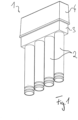
Figur 2 zeigt die Durchführung 1 in einer Einbausituation, im Erdreich 20 wurde ein Graben 21 ausgehoben. Oberhalb davon soll dann später die Bodenplatte gegossen und das Gebäude errichtet werden. Die Durchführung 1 wird mit einer Aufstellvorrichtung 22, vorliegend einem höhenverstellbaren Erdspieß, auf einer solchen Höhe eingerichtet, dass das obere Ende des Grundkörpers 3 mit der Oberkante 23 der später gegossenen Bodenplatte zusammenfällt. An die Mantelrohre 2 wird jeweils ein Schutzrohr 24 angeschlossen (eines davon ist skizziert), die - Schutzrohre 24 verlaufen in dem Graben 21 bis zu einer Anschlussstelle an der Straße.
- Nach einem Verfüllen des Grabens 21 wird die Bodenplatte 30 betoniert, vergleiche
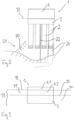
Figur 3 . Auf der Bodenplatte 30, von deren Oberkante 23 aufwärts, wird ein Fußbodenaufbau 31 (Estrich etc.) aufgebracht. Dessen Oberkante 32 ist die Oberkante des Bodenelements 23 (das sich aus Bodenplatte 30 und Fußbodenaufbau 31 zusammensetzt). Der Grundkörper 3 sitzt in der Bodenplatte 31, der Vergusskörper 4 in dem Fußbodenaufbau 31, ein oberer Abschnitt 4.1 steht jedoch über (nur der untere Abschnitt 4.2 wird seitlich von dem Fußbodenaufbau 31 umschlossen). Im Zuge der weiteren Montage wird der obere Abschnitt 4.1 abgetrennt, bspw. mit einem Messer. Damit wird das Innere des Grundkörpers 3 zugänglich (von dem Vergusskörper 4 bleibt nur eine umlaufende Seitenwand stehen, vergleiche auchFigur 6 zur Illustration. -
Figur 4 zeigt die Durchführung in einer Ansicht von schräg oben, und zwar ohne den Vergusskörper. Die Mantelrohre 2 sind von unten in den Grundkörper 3 eingesteckt, mit dem Entfernen des oberen Abschnitts 4.1 des Vergusskörpers 4 sind sie von oben zugänglich. Von oben wird dann der inFigur 5 gezeigte Montageaufsatz 50 eingeschoben. Dieser weist eine Flanschplatte 51 auf, an der sich nach unten erstreckende Rohrstutzen 52 angeordnet sind. Jeder der Rohrstutzen 52 wird in ein jeweiliges Mantelrohr 2 eingeschoben und ist mit einer hier nicht dargestellten Dichtung dagegen gedichtet. Die Montageplatte 51 sitzt auf der Oberkante 32 des Fußbodenaufbaus 31 auf. - Durch jedes der insgesamt vier Rohrsysteme (aus Mantelrohr, Rohrstutzen und Schutzrohr) kann dann die eigentliche Leitung 53 verlegt und gegen den Montageaufsatz 50 gedichtet werden.
-
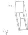
Figur 6 zeigt allein den Vergusskörper 4 in einer Ansicht von unten, es ist also die Unterseite des Deckels und sind ferner 2 Seitenwände von innen zu erkennen. In einer hier nicht dargestellten Variante können zwischen den lang gestreckten Seitenwänden auch Stege verlaufen und eine Verstrebung zur Stabilisierung der Seitenwände bilden.
Claims (14)
- Verwendung einer Durchführung (1) zum Eingießen in ein Bodenelement (33) und Hindurchführen einer Leitung (53),welche Durchführung (1) ein Mantelrohr (2) und einen Vergusskörper (4) aufweist,die solchermaßen in das Bodenelement (33) eingegossen werden, dass sich das Mantelrohr (2) unterhalb des Vergusskörpers (4) erstreckt und ein oberer Abschnitt (4.1) des Vergusskörpers (4) gegenüber einer Oberkante (32) des Bodenelements (33) übersteht,wobei nach dem Eingießen der obere Abschnitt (4.1) des Vergusskörpers (4) entfernt und ein Montageaufsatz (50) mit einem Rohrstutzen (52) in einer Montageposition relativ zu dem Mantelrohr (2) positioniert wird,dadurch gekennzeichnet dassder Vergusskörper (4) aus einem geschäumten Kunststoffmaterial vorgesehen ist.
- Verwendung nach Anspruch 1, bei welcher das geschäumte Kunststoffmaterial des Vergusskörpers (4) expandiertes Polypropylen ist.
- Verwendung nach Anspruch 1 oder 2, bei welcher der Vergusskörper (4), bevor der obere Abschnitt (4.1) davon entfernt wird, das Mantelrohr (2) nach oben hin abdeckt.
- Verwendung nach einem der vorstehenden Ansprüche, bei welcher der Montageaufsatz (50) erst an die Durchführung (1) angesetzt wird, nachdem das Mantelrohr (2) und der Vergusskörper (4) eingegossen wurden.
- Verwendung nach einem der vorstehenden Ansprüche, bei welcher die Durchführung (1) einen Grundkörper (3) aufweist, auf den der Vergusskörper (4) aufgesetzt ist, wobei eine Seitenwand des Grundkörpers (3) einen Kragen bildet, welcher den Vergusskörper (4) nach außen hin einfasst.
- Verwendung nach einem der vorstehenden Ansprüche, bei welcher die Durchführung (1) einen Grundkörper (3) mit einer Seitenwand aufweist, wobei die Durchführung (1) auf einer solchen Höhe in eine Bodenplatte (30) des Bodenelements (33) eingegossen wird, dass eine Oberkante (32) der Bodenplatte (30) am oberen Ende der Seitenwand liegt.
- Verwendung nach einem der vorstehenden Ansprüche, bei welcher die Durchführung (1) einen Grundkörper (3) aufweist, wobei der Montageaufsatz (50) in der Montageposition an dem Grundkörper (3) befestigt ist.
- Verwendung nach einem der vorstehenden Ansprüche, bei welcher die Durchführung (1) einen Grundkörper (3) und eine Aufstellvorrichtung (22) aufweist, mit welcher die Durchführung (1) vor dem Gießen des Bodenelements (33) relativ zum Erdreich (20) platziert wird, wobei die Aufstellvorrichtung (22) an dem Grundkörper (3) befestigt ist.
- Verwendung nach einem der vorstehenden Ansprüche, bei welcher die Durchführung einen Grundkörper (3) aufweist, wobei an dem Grundkörper (3) ein Flansch vorgesehen ist, wobei die Durchführung (1) auf einer solchen Höhe in eine Bodenplatte (30) des Bodenelements (33) eingegossen wird, dass der Flansch bündig mit einer Oberkante (32) der Bodenplatte (30) liegt, wobei vor einem Erstellen eines Fußbodenaufbaus (31) eine Flächendichtung auf der Bodenplatte (30) an den Flansch angearbeitet wird.
- Verwendung nach einem der vorstehenden Ansprüche, bei welcher die Durchführung (1) einen Grundkörper (3) und eine Mehrzahl Mantelrohre (2) aufweist, die mit dem Grundkörper (3) zusammengesetzt sind und von diesem in einer Relativposition zueinander gehalten werden.
- Verwendung nach Anspruch 10, bei welcher die Durchführung (1) zusätzlich ein Halteteil (6) aufweist, das unterhalb des Grundkörpers (3) angeordnet ist und die Mantelrohre (2) in einer Relativposition zueinander hält.
- Verwendung nach Anspruch 11, bei welcher das Halteteil (6) zu den Mantelrohren (2) gedichtet ist.
- Verwendung nach einem der vorstehenden Ansprüche, bei welcher die Durchführung (1) eine Mehrzahl Mantelrohre (2) aufweist und der Vergusskörper (4) in seinem Inneren mit einer Verstrebung geformt ist, die einander entgegengesetzte Außenwandbereiche des Vergusskörpers (4) relativ zueinander stabilisiert, dabei aber Durchtritte in dem Vergusskörper (4) freilässt, die vertikal mit den Mantelrohren (2) fluchten.
- Verwendung nach einem der vorstehenden Ansprüche, bei welcher das Bodenelement (33) eine Bodenplatte (30) und einen Fußbodenaufbau (31) umfasst, wobei eine Oberkante (32) des Fußbodenaufbaus (31) die Oberkante (32) des Bodenelements (33) bildet.
Priority Applications (1)
| Application Number | Priority Date | Filing Date | Title |
|---|---|---|---|
| EP25152068.0A EP4518063B1 (de) | 2018-07-18 | 2019-07-17 | Verwendung einer durchführung zum eingiessen in ein bodenelement |
Applications Claiming Priority (4)
| Application Number | Priority Date | Filing Date | Title |
|---|---|---|---|
| DE102018005717.9A DE102018005717A1 (de) | 2018-07-18 | 2018-07-18 | Verwendung einer Durchführung zum Eingießen in ein Bodenelement |
| DE102018005720.9A DE102018005720B4 (de) | 2018-07-18 | 2018-07-18 | Verwendung einer Durchführung zum Eingießen in eine Bodenplatte |
| DE102018005718.7A DE102018005718B4 (de) | 2018-07-18 | 2018-07-18 | Verwendung einer Durchführung zum Eingießen in eine Bodenplatte |
| DE102018005719.5A DE102018005719B4 (de) | 2018-07-18 | 2018-07-18 | Verwendung einer Durchführung zum Eingießen in eine Bodenplatte |
Related Child Applications (2)
| Application Number | Title | Priority Date | Filing Date |
|---|---|---|---|
| EP25152068.0A Division EP4518063B1 (de) | 2018-07-18 | 2019-07-17 | Verwendung einer durchführung zum eingiessen in ein bodenelement |
| EP25152068.0A Division-Into EP4518063B1 (de) | 2018-07-18 | 2019-07-17 | Verwendung einer durchführung zum eingiessen in ein bodenelement |
Publications (2)
| Publication Number | Publication Date |
|---|---|
| EP3604709A1 EP3604709A1 (de) | 2020-02-05 |
| EP3604709B1 true EP3604709B1 (de) | 2025-02-19 |
Family
ID=67437844
Family Applications (2)
| Application Number | Title | Priority Date | Filing Date |
|---|---|---|---|
| EP25152068.0A Active EP4518063B1 (de) | 2018-07-18 | 2019-07-17 | Verwendung einer durchführung zum eingiessen in ein bodenelement |
| EP19186764.7A Active EP3604709B1 (de) | 2018-07-18 | 2019-07-17 | Verwendung einer durchführung zum eingiessen in ein bodenelement |
Family Applications Before (1)
| Application Number | Title | Priority Date | Filing Date |
|---|---|---|---|
| EP25152068.0A Active EP4518063B1 (de) | 2018-07-18 | 2019-07-17 | Verwendung einer durchführung zum eingiessen in ein bodenelement |
Country Status (1)
| Country | Link |
|---|---|
| EP (2) | EP4518063B1 (de) |
Families Citing this family (4)
| Publication number | Priority date | Publication date | Assignee | Title |
|---|---|---|---|---|
| DE202020102547U1 (de) | 2020-05-06 | 2021-09-15 | Doyma Gmbh & Co | Hauseinführung, sowie Hauseinführungsanordnung |
| EP4047766B1 (de) * | 2021-02-22 | 2025-07-30 | Hauff-Technik GmbH & Co. KG | Gebäudeinstallationsanordnung |
| CH718543A2 (de) * | 2021-04-16 | 2022-10-31 | Agro Ag | Mehrfacheinführung. |
| CN114086762B (zh) * | 2021-11-30 | 2023-01-31 | 中力建设集团有限公司 | 一种楼面混凝土浇筑方法 |
Citations (2)
| Publication number | Priority date | Publication date | Assignee | Title |
|---|---|---|---|---|
| DE202012009132U1 (de) * | 2012-09-24 | 2014-01-08 | Hauff-Technik Gmbh & Co Kg | Leitung in einem Wand- oder Bodenelement |
| US20160090738A1 (en) * | 2011-10-28 | 2016-03-31 | Wladimir de Freitas Silvestre | Supporting element for pipes in buildings and application method of a pipe supporting element in a flagstone |
Family Cites Families (3)
| Publication number | Priority date | Publication date | Assignee | Title |
|---|---|---|---|---|
| DE102005041176B4 (de) * | 2005-01-28 | 2008-12-24 | Lic Langmatz Gmbh | Hauseinführung für ein bevorzugt kellerloses Gebäude |
| DE202013007621U1 (de) * | 2013-08-28 | 2013-09-18 | Hauff-Technik Gmbh & Co. Kg | Verbesserte höhenanpassbare Hauseinführung für eine Gebäudebodenplatte |
| DE102016010096A1 (de) * | 2016-08-24 | 2018-03-01 | Hauff-Technik Gmbh & Co. Kg | Verwendung einer Gebäudeeinführung zum Einbau in eine Gebäudeaußenwand |
-
2019
- 2019-07-17 EP EP25152068.0A patent/EP4518063B1/de active Active
- 2019-07-17 EP EP19186764.7A patent/EP3604709B1/de active Active
Patent Citations (2)
| Publication number | Priority date | Publication date | Assignee | Title |
|---|---|---|---|---|
| US20160090738A1 (en) * | 2011-10-28 | 2016-03-31 | Wladimir de Freitas Silvestre | Supporting element for pipes in buildings and application method of a pipe supporting element in a flagstone |
| DE202012009132U1 (de) * | 2012-09-24 | 2014-01-08 | Hauff-Technik Gmbh & Co Kg | Leitung in einem Wand- oder Bodenelement |
Also Published As
| Publication number | Publication date |
|---|---|
| EP3604709A1 (de) | 2020-02-05 |
| EP4518063A2 (de) | 2025-03-05 |
| EP4518063A3 (de) | 2025-04-30 |
| EP4518063B1 (de) | 2025-12-10 |
Similar Documents
| Publication | Publication Date | Title |
|---|---|---|
| EP3604709B1 (de) | Verwendung einer durchführung zum eingiessen in ein bodenelement | |
| EP3031990B1 (de) | Bodenablauf | |
| EP2631370B1 (de) | Unterflur-Schacht | |
| DE102020004384A1 (de) | Bauschutz und Vorwandelement mit Bauschutz | |
| DE102018005720B4 (de) | Verwendung einer Durchführung zum Eingießen in eine Bodenplatte | |
| DE102018005717A1 (de) | Verwendung einer Durchführung zum Eingießen in ein Bodenelement | |
| DE102012101366B3 (de) | Unterflur-Schacht, Bausatz zum Herstellen und Verfahren zum Einbau dafür | |
| DE102018005718B4 (de) | Verwendung einer Durchführung zum Eingießen in eine Bodenplatte | |
| DE10227217B4 (de) | Unterflur-Bodendose | |
| DE202011050243U1 (de) | Durchführung für eine Gebäudehülle | |
| EP3795759B1 (de) | Schutzrohrsystem | |
| DE102018005719B4 (de) | Verwendung einer Durchführung zum Eingießen in eine Bodenplatte | |
| EP3660991B1 (de) | Anschlussgehäusevorrichtung | |
| EP4148926B1 (de) | Verwendung einer gehäusevorrichtung | |
| EP3107166B1 (de) | Durchführung zum hindurchführen einer leitung durch ein wand- oder bodenelement | |
| DE202020102819U1 (de) | Bauschutzvorrichtung für an einer Sanitärkeramik anzuschließende Rohrleitungen sowie Montagegestell für eine Sanitärkeramik mit einer solchen Bauschutzvorrichtung | |
| EP4148927B1 (de) | Verwendung einer gehäusevorrichtung | |
| DE202015009557U1 (de) | Durchführung zum Hindurchführen einer Leitung durch ein Wand- oder Bodenelement | |
| DE4241264C2 (de) | Schachtabdeckung | |
| DE19750709C1 (de) | Einrichtung zum Abdichten eines in einer Deckenbohrung oder einer Deckenausnehmung angeordneten Bodenablaufs | |
| DE9213661U1 (de) | Domschacht für einen Erdtank | |
| DE20209454U1 (de) | Unterflur-Bodendose | |
| DE2311031A1 (de) | Abflussanordnung fuer gebaeude | |
| DE102022112807A1 (de) | Hausdurchführung zum Durchführen mindestens einer Leitung durch eine Bodenplatte und Bodenplatte mit selbiger | |
| DE102018001419A1 (de) | Durchführung zum Hindurchführen einer Leitung |
Legal Events
| Date | Code | Title | Description |
|---|---|---|---|
| PUAI | Public reference made under article 153(3) epc to a published international application that has entered the european phase |
Free format text: ORIGINAL CODE: 0009012 |
|
| STAA | Information on the status of an ep patent application or granted ep patent |
Free format text: STATUS: THE APPLICATION HAS BEEN PUBLISHED |
|
| AK | Designated contracting states |
Kind code of ref document: A1 Designated state(s): AL AT BE BG CH CY CZ DE DK EE ES FI FR GB GR HR HU IE IS IT LI LT LU LV MC MK MT NL NO PL PT RO RS SE SI SK SM TR |
|
| AX | Request for extension of the european patent |
Extension state: BA ME |
|
| STAA | Information on the status of an ep patent application or granted ep patent |
Free format text: STATUS: REQUEST FOR EXAMINATION WAS MADE |
|
| 17P | Request for examination filed |
Effective date: 20200803 |
|
| RBV | Designated contracting states (corrected) |
Designated state(s): AL AT BE BG CH CY CZ DE DK EE ES FI FR GB GR HR HU IE IS IT LI LT LU LV MC MK MT NL NO PL PT RO RS SE SI SK SM TR |
|
| STAA | Information on the status of an ep patent application or granted ep patent |
Free format text: STATUS: EXAMINATION IS IN PROGRESS |
|
| 17Q | First examination report despatched |
Effective date: 20220530 |
|
| GRAP | Despatch of communication of intention to grant a patent |
Free format text: ORIGINAL CODE: EPIDOSNIGR1 |
|
| STAA | Information on the status of an ep patent application or granted ep patent |
Free format text: STATUS: GRANT OF PATENT IS INTENDED |
|
| INTG | Intention to grant announced |
Effective date: 20240430 |
|
| GRAJ | Information related to disapproval of communication of intention to grant by the applicant or resumption of examination proceedings by the epo deleted |
Free format text: ORIGINAL CODE: EPIDOSDIGR1 |
|
| STAA | Information on the status of an ep patent application or granted ep patent |
Free format text: STATUS: EXAMINATION IS IN PROGRESS |
|
| GRAP | Despatch of communication of intention to grant a patent |
Free format text: ORIGINAL CODE: EPIDOSNIGR1 |
|
| STAA | Information on the status of an ep patent application or granted ep patent |
Free format text: STATUS: GRANT OF PATENT IS INTENDED |
|
| INTC | Intention to grant announced (deleted) | ||
| INTG | Intention to grant announced |
Effective date: 20240912 |
|
| GRAS | Grant fee paid |
Free format text: ORIGINAL CODE: EPIDOSNIGR3 |
|
| GRAA | (expected) grant |
Free format text: ORIGINAL CODE: 0009210 |
|
| STAA | Information on the status of an ep patent application or granted ep patent |
Free format text: STATUS: THE PATENT HAS BEEN GRANTED |
|
| AK | Designated contracting states |
Kind code of ref document: B1 Designated state(s): AL AT BE BG CH CY CZ DE DK EE ES FI FR GB GR HR HU IE IS IT LI LT LU LV MC MK MT NL NO PL PT RO RS SE SI SK SM TR |
|
| REG | Reference to a national code |
Ref country code: GB Ref legal event code: FG4D Free format text: NOT ENGLISH |
|
| REG | Reference to a national code |
Ref country code: CH Ref legal event code: EP |
|
| REG | Reference to a national code |
Ref country code: IE Ref legal event code: FG4D Free format text: LANGUAGE OF EP DOCUMENT: GERMAN |
|
| REG | Reference to a national code |
Ref country code: DE Ref legal event code: R096 Ref document number: 502019012943 Country of ref document: DE |
|
| P01 | Opt-out of the competence of the unified patent court (upc) registered |
Free format text: CASE NUMBER: APP_10003/2025 Effective date: 20250227 |
|
| REG | Reference to a national code |
Ref country code: NL Ref legal event code: MP Effective date: 20250219 |
|
| PG25 | Lapsed in a contracting state [announced via postgrant information from national office to epo] |
Ref country code: RS Free format text: LAPSE BECAUSE OF FAILURE TO SUBMIT A TRANSLATION OF THE DESCRIPTION OR TO PAY THE FEE WITHIN THE PRESCRIBED TIME-LIMIT Effective date: 20250519 |
|
| PG25 | Lapsed in a contracting state [announced via postgrant information from national office to epo] |
Ref country code: FI Free format text: LAPSE BECAUSE OF FAILURE TO SUBMIT A TRANSLATION OF THE DESCRIPTION OR TO PAY THE FEE WITHIN THE PRESCRIBED TIME-LIMIT Effective date: 20250219 |
|
| PG25 | Lapsed in a contracting state [announced via postgrant information from national office to epo] |
Ref country code: PL Free format text: LAPSE BECAUSE OF FAILURE TO SUBMIT A TRANSLATION OF THE DESCRIPTION OR TO PAY THE FEE WITHIN THE PRESCRIBED TIME-LIMIT Effective date: 20250219 |
|
| PG25 | Lapsed in a contracting state [announced via postgrant information from national office to epo] |
Ref country code: ES Free format text: LAPSE BECAUSE OF FAILURE TO SUBMIT A TRANSLATION OF THE DESCRIPTION OR TO PAY THE FEE WITHIN THE PRESCRIBED TIME-LIMIT Effective date: 20250219 |
|
| REG | Reference to a national code |
Ref country code: LT Ref legal event code: MG9D |
|
| PG25 | Lapsed in a contracting state [announced via postgrant information from national office to epo] |
Ref country code: NO Free format text: LAPSE BECAUSE OF FAILURE TO SUBMIT A TRANSLATION OF THE DESCRIPTION OR TO PAY THE FEE WITHIN THE PRESCRIBED TIME-LIMIT Effective date: 20250519 Ref country code: IS Free format text: LAPSE BECAUSE OF FAILURE TO SUBMIT A TRANSLATION OF THE DESCRIPTION OR TO PAY THE FEE WITHIN THE PRESCRIBED TIME-LIMIT Effective date: 20250619 |
|
| PG25 | Lapsed in a contracting state [announced via postgrant information from national office to epo] |
Ref country code: NL Free format text: LAPSE BECAUSE OF FAILURE TO SUBMIT A TRANSLATION OF THE DESCRIPTION OR TO PAY THE FEE WITHIN THE PRESCRIBED TIME-LIMIT Effective date: 20250219 |
|
| PG25 | Lapsed in a contracting state [announced via postgrant information from national office to epo] |
Ref country code: HR Free format text: LAPSE BECAUSE OF FAILURE TO SUBMIT A TRANSLATION OF THE DESCRIPTION OR TO PAY THE FEE WITHIN THE PRESCRIBED TIME-LIMIT Effective date: 20250219 |
|
| PG25 | Lapsed in a contracting state [announced via postgrant information from national office to epo] |
Ref country code: PT Free format text: LAPSE BECAUSE OF FAILURE TO SUBMIT A TRANSLATION OF THE DESCRIPTION OR TO PAY THE FEE WITHIN THE PRESCRIBED TIME-LIMIT Effective date: 20250620 Ref country code: LV Free format text: LAPSE BECAUSE OF FAILURE TO SUBMIT A TRANSLATION OF THE DESCRIPTION OR TO PAY THE FEE WITHIN THE PRESCRIBED TIME-LIMIT Effective date: 20250219 |
|
| PG25 | Lapsed in a contracting state [announced via postgrant information from national office to epo] |
Ref country code: GR Free format text: LAPSE BECAUSE OF FAILURE TO SUBMIT A TRANSLATION OF THE DESCRIPTION OR TO PAY THE FEE WITHIN THE PRESCRIBED TIME-LIMIT Effective date: 20250520 Ref country code: BG Free format text: LAPSE BECAUSE OF FAILURE TO SUBMIT A TRANSLATION OF THE DESCRIPTION OR TO PAY THE FEE WITHIN THE PRESCRIBED TIME-LIMIT Effective date: 20250219 |
|
| PG25 | Lapsed in a contracting state [announced via postgrant information from national office to epo] |
Ref country code: SE Free format text: LAPSE BECAUSE OF FAILURE TO SUBMIT A TRANSLATION OF THE DESCRIPTION OR TO PAY THE FEE WITHIN THE PRESCRIBED TIME-LIMIT Effective date: 20250219 |
|
| PG25 | Lapsed in a contracting state [announced via postgrant information from national office to epo] |
Ref country code: SM Free format text: LAPSE BECAUSE OF FAILURE TO SUBMIT A TRANSLATION OF THE DESCRIPTION OR TO PAY THE FEE WITHIN THE PRESCRIBED TIME-LIMIT Effective date: 20250219 |
|
| PG25 | Lapsed in a contracting state [announced via postgrant information from national office to epo] |
Ref country code: DK Free format text: LAPSE BECAUSE OF FAILURE TO SUBMIT A TRANSLATION OF THE DESCRIPTION OR TO PAY THE FEE WITHIN THE PRESCRIBED TIME-LIMIT Effective date: 20250219 |
|
| PGFP | Annual fee paid to national office [announced via postgrant information from national office to epo] |
Ref country code: DE Payment date: 20250722 Year of fee payment: 7 |
|
| PG25 | Lapsed in a contracting state [announced via postgrant information from national office to epo] |
Ref country code: IT Free format text: LAPSE BECAUSE OF FAILURE TO SUBMIT A TRANSLATION OF THE DESCRIPTION OR TO PAY THE FEE WITHIN THE PRESCRIBED TIME-LIMIT Effective date: 20250219 |
|
| PGFP | Annual fee paid to national office [announced via postgrant information from national office to epo] |
Ref country code: AT Payment date: 20250724 Year of fee payment: 7 |
|
| PGFP | Annual fee paid to national office [announced via postgrant information from national office to epo] |
Ref country code: CH Payment date: 20250801 Year of fee payment: 7 |
|
| PG25 | Lapsed in a contracting state [announced via postgrant information from national office to epo] |
Ref country code: EE Free format text: LAPSE BECAUSE OF FAILURE TO SUBMIT A TRANSLATION OF THE DESCRIPTION OR TO PAY THE FEE WITHIN THE PRESCRIBED TIME-LIMIT Effective date: 20250219 Ref country code: CZ Free format text: LAPSE BECAUSE OF FAILURE TO SUBMIT A TRANSLATION OF THE DESCRIPTION OR TO PAY THE FEE WITHIN THE PRESCRIBED TIME-LIMIT Effective date: 20250219 |
|
| PG25 | Lapsed in a contracting state [announced via postgrant information from national office to epo] |
Ref country code: RO Free format text: LAPSE BECAUSE OF FAILURE TO SUBMIT A TRANSLATION OF THE DESCRIPTION OR TO PAY THE FEE WITHIN THE PRESCRIBED TIME-LIMIT Effective date: 20250219 |
|
| PG25 | Lapsed in a contracting state [announced via postgrant information from national office to epo] |
Ref country code: SK Free format text: LAPSE BECAUSE OF FAILURE TO SUBMIT A TRANSLATION OF THE DESCRIPTION OR TO PAY THE FEE WITHIN THE PRESCRIBED TIME-LIMIT Effective date: 20250219 |
|
| REG | Reference to a national code |
Ref country code: DE Ref legal event code: R097 Ref document number: 502019012943 Country of ref document: DE |
|
| PLBE | No opposition filed within time limit |
Free format text: ORIGINAL CODE: 0009261 |
|
| STAA | Information on the status of an ep patent application or granted ep patent |
Free format text: STATUS: NO OPPOSITION FILED WITHIN TIME LIMIT |
|
| 26N | No opposition filed |
Effective date: 20251120 |