EP3603838B1 - Formsystem und formverfahren - Google Patents
Formsystem und formverfahren Download PDFInfo
- Publication number
- EP3603838B1 EP3603838B1 EP18772649.2A EP18772649A EP3603838B1 EP 3603838 B1 EP3603838 B1 EP 3603838B1 EP 18772649 A EP18772649 A EP 18772649A EP 3603838 B1 EP3603838 B1 EP 3603838B1
- Authority
- EP
- European Patent Office
- Prior art keywords
- metal pipe
- pipe material
- dies
- forming apparatus
- forming
- Prior art date
- Legal status (The legal status is an assumption and is not a legal conclusion. Google has not performed a legal analysis and makes no representation as to the accuracy of the status listed.)
- Active
Links
Images


Classifications
-
- B—PERFORMING OPERATIONS; TRANSPORTING
- B21—MECHANICAL METAL-WORKING WITHOUT ESSENTIALLY REMOVING MATERIAL; PUNCHING METAL
- B21D—WORKING OR PROCESSING OF SHEET METAL OR METAL TUBES, RODS OR PROFILES WITHOUT ESSENTIALLY REMOVING MATERIAL; PUNCHING METAL
- B21D26/00—Shaping without cutting otherwise than using rigid devices or tools or yieldable or resilient pads, i.e. applying fluid pressure or magnetic forces
- B21D26/02—Shaping without cutting otherwise than using rigid devices or tools or yieldable or resilient pads, i.e. applying fluid pressure or magnetic forces by applying fluid pressure
- B21D26/033—Deforming tubular bodies
-
- B—PERFORMING OPERATIONS; TRANSPORTING
- B21—MECHANICAL METAL-WORKING WITHOUT ESSENTIALLY REMOVING MATERIAL; PUNCHING METAL
- B21D—WORKING OR PROCESSING OF SHEET METAL OR METAL TUBES, RODS OR PROFILES WITHOUT ESSENTIALLY REMOVING MATERIAL; PUNCHING METAL
- B21D26/00—Shaping without cutting otherwise than using rigid devices or tools or yieldable or resilient pads, i.e. applying fluid pressure or magnetic forces
- B21D26/02—Shaping without cutting otherwise than using rigid devices or tools or yieldable or resilient pads, i.e. applying fluid pressure or magnetic forces by applying fluid pressure
- B21D26/053—Shaping without cutting otherwise than using rigid devices or tools or yieldable or resilient pads, i.e. applying fluid pressure or magnetic forces by applying fluid pressure characterised by the material of the blanks
-
- B—PERFORMING OPERATIONS; TRANSPORTING
- B21—MECHANICAL METAL-WORKING WITHOUT ESSENTIALLY REMOVING MATERIAL; PUNCHING METAL
- B21D—WORKING OR PROCESSING OF SHEET METAL OR METAL TUBES, RODS OR PROFILES WITHOUT ESSENTIALLY REMOVING MATERIAL; PUNCHING METAL
- B21D39/00—Application of procedures in order to connect objects or parts, e.g. coating with sheet metal otherwise than by plating; Tube expanders
- B21D39/02—Application of procedures in order to connect objects or parts, e.g. coating with sheet metal otherwise than by plating; Tube expanders of sheet metal by folding, e.g. connecting edges of a sheet to form a cylinder
-
- B—PERFORMING OPERATIONS; TRANSPORTING
- B21—MECHANICAL METAL-WORKING WITHOUT ESSENTIALLY REMOVING MATERIAL; PUNCHING METAL
- B21D—WORKING OR PROCESSING OF SHEET METAL OR METAL TUBES, RODS OR PROFILES WITHOUT ESSENTIALLY REMOVING MATERIAL; PUNCHING METAL
- B21D43/00—Feeding, positioning or storing devices combined with, or arranged in, or specially adapted for use in connection with, apparatus for working or processing sheet metal, metal tubes or metal profiles; Associations therewith of cutting devices
- B21D43/003—Positioning devices
-
- B—PERFORMING OPERATIONS; TRANSPORTING
- B21—MECHANICAL METAL-WORKING WITHOUT ESSENTIALLY REMOVING MATERIAL; PUNCHING METAL
- B21D—WORKING OR PROCESSING OF SHEET METAL OR METAL TUBES, RODS OR PROFILES WITHOUT ESSENTIALLY REMOVING MATERIAL; PUNCHING METAL
- B21D43/00—Feeding, positioning or storing devices combined with, or arranged in, or specially adapted for use in connection with, apparatus for working or processing sheet metal, metal tubes or metal profiles; Associations therewith of cutting devices
- B21D43/006—Feeding elongated articles, such as tubes, bars, or profiles
-
- B—PERFORMING OPERATIONS; TRANSPORTING
- B21—MECHANICAL METAL-WORKING WITHOUT ESSENTIALLY REMOVING MATERIAL; PUNCHING METAL
- B21D—WORKING OR PROCESSING OF SHEET METAL OR METAL TUBES, RODS OR PROFILES WITHOUT ESSENTIALLY REMOVING MATERIAL; PUNCHING METAL
- B21D43/00—Feeding, positioning or storing devices combined with, or arranged in, or specially adapted for use in connection with, apparatus for working or processing sheet metal, metal tubes or metal profiles; Associations therewith of cutting devices
- B21D43/02—Advancing work in relation to the stroke of the die or tool
Definitions
- the present invention relates to a forming system and a forming method.
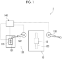
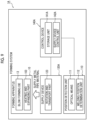
- PTL 1 discloses a forming system which includes a forming apparatus having a set of dies and a heating and expanding part which heats a metal pipe material disposed between the set of dies and supplies a gas into the metal pipe material to expand the metal pipe material.
- a plate thickness of the metal pipe material becomes thin according to a pipe expansion rate of the metal pipe material.
- the smaller the deformation resistance of the metal pipe material the larger the pipe expansion rate of the metal pipe material is, and thus the plate thickness becomes thinner.
- the metal pipe material is made into a pipe shape by rounding a metal plate material and welding a connection portion.
- a metal pipe material having such a welded portion if the metal pipe material is heated, the deformation resistance of the welded portion tends to be reduced compared to the plate material portion.
- the plate thickness of the welded portion of the metal pipe material heated to a high temperature becomes particularly thin locally, and thus there is a concern that the metal pipe material may be damaged starting from the welded portion.
- the present invention has an object to provide a forming system and a forming method, in which it is possible to suppress breakage of a metal pipe material starting from a welded portion at the time of forming of a metal pipe.
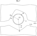
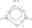
- the metal pipe material 14 may be disposed between the set of blow forming dies 13 such that the welded portion 14b is located on the straight line P2 connecting the shortest position R2 which is a position at which the distance from the center C of the metal pipe material 14 is the shortest, on the surface of the blow forming die 13, and the center C of the metal pipe material 14, in a case of being viewed from the extension direction D of the metal pipe material 14 in a state where the metal pipe material 14 is disposed between the set of blow forming dies 13.
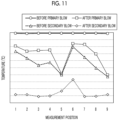
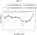
- the plate thickness or the temperature is shown to be divided into measurement timings before the primary blow, after the primary blow, before the secondary blow, and after the secondary blow.
- before the primary blow refers to before the blow forming work on the metal pipe material 14 is started
- after the secondary blow refers to after the blow forming work on the metal pipe material 14 is completed and the metal pipe 90 is formed.
Landscapes
- Engineering & Computer Science (AREA)
- Mechanical Engineering (AREA)
- Physics & Mathematics (AREA)
- Fluid Mechanics (AREA)
- Shaping Metal By Deep-Drawing, Or The Like (AREA)
Claims (8)
- Formungssystem (1), das ein Metallrohr (90) aus einem zylindrischen Metallrohrmaterial (14) formt, das einen geschweißten Abschnitt (14b) aufweist, bei dem Endabschnitte (14a) eines Plattenmaterials miteinander verschweißt sind, wobei das Formungssystem (1) umfasst:
eine Formvorrichtung (10), die einen Satz von Formen (13) und ein Heiz- und Expansionsteil (103) aufweist, das das Metallrohrmaterial (14), das zwischen dem Satz von Formen (13) angeordnet ist, erwärmt und ein Gas in das Metallrohrmaterial (14) zuführt, um das Metallrohrmaterial (14) zu expandieren;
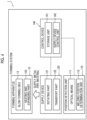
dadurch gekennzeichnet, dass das Formungssystem weiter umfasst:eine Zufuhrvorrichtung (120), die das Metallrohrmaterial (14) um eine Mittelachse des Metallrohrmaterials (14) dreht und das Metallrohrmaterial (14) der Formvorrichtung (10) zuführt;eine Positionsdetektionseinheit (110), die eine Richtung detektiert, in der sich der geschweißte Abschnitt (14b) in Bezug auf eine Mitte des Metallrohrmaterials (14) bei einem Fall von Betrachtung aus einer Extensionsrichtung befindet, bevor das Metallrohrmaterial (14) der Formvorrichtung (10) durch die Zufuhrvorrichtung (120) zugeführt wird; undeine Steuervorrichtung (140), die eine Speichereinheit (141) und eine Steuereinheit (142) umfasst und einen Betrieb der Zufuhrvorrichtung (120) steuert,wobeibei einem Fall, bei dem eine Position, bei der ein Abstand von der Mitte des Metallrohrmaterials (14) am längsten ist, an einer Fläche von einer von den Formen des Satzes von Formen (13) in einem Raum, der von der Kavität des Satzes an Formen gebildet wird, bei einem Fall von Betrachtung aus der Extensionsrichtung des Metallrohrmaterials (14), in einem Zustand, bei dem das Metallrohrmaterial (14) zwischen dem Satz von Formen (13) angeordnet ist, eingestellt ist, eine längste Position (R1) zu sein,die Speichereinheit (141) Informationen über die längste Position (R1) speichert, unddie Steuereinheit (142) auf der Grundlage der in der Speichereinheit (141) gespeicherten Information über die längste Position (R1) eine Zufuhr des Metallrohrmaterials (14) zu der Formvorrichtung (10) durch die Zufuhrvorrichtung (120) so steuert, dass sich der geschweißte Abschnitt (14b) nicht auf einer geraden Linie befindet, die die längste Position (R1) und die Mitte des Metallrohrmaterials (14) verbindet. - Formungssystem (1) nach Anspruch 1,wobei die Zufuhrvorrichtung (120) umfasstein Drehteil (121), das in der Lage ist, das Metallrohrmaterial (14) um die Mittelachse zu drehen, undein Transportteil (122), das in der Lage ist, das Metallrohrmaterial (14) zu greifen, und in der Lage ist, das gegriffene Metallrohrmaterial (14) zu der Formvorrichtung (10) zu transportieren, unddie Steuereinheit (140)einen Betrieb des Drehteils (121) steuert, um eine Richtung anzupassen, in der sich der geschweißte Abschnitt (14b) in Bezug auf die Mitte des Metallrohrmaterials (14) bei einem Fall von Betrachtung aus der Extensionsrichtung befindet, durch Drehen des Metallrohrmaterials (14) um die Mittelachse durch das Drehteil (121), wenn das Metallrohrmaterial (14) der Formvorrichtung (10) durch die Zufuhrvorrichtung (120) zugeführt wird, undeinen Betrieb des Transportteils (122) steuert, um das Metallrohrmaterial (14) durch das Transportteil (122) zu greifen und zu der Formvorrichtung (10) zu transportieren.
- Formungssystem (1) nach Anspruch 1,wobei die Zufuhrvorrichtung (120) ein Dreh- und Transportteil (123) umfasst, das aus einem Gelenkarm aufgebaut ist, der in der Lage ist, das Metallrohrmaterial (14) zu greifen und das gegriffene Metallrohrmaterial (14) um die Mittelachse zu drehen, und in der Lage ist, das Metallrohrmaterial (14) zu der Formvorrichtung (10) zu transportieren, unddie Steuereinheit (142) einen Betrieb des Dreh- und Transportteils (123) steuert, um eine Richtung anzupassen, in der der geschweißte Abschnitt (14b) sich in Bezug auf die Mitte des Metallrohrmaterials (14) bei einem Fall von Betrachtung aus der Extensionsrichtung befindet, durch Greifen des Metallrohrmaterials (14) und Drehen des Metallrohrmaterials (14) um die Mittelachse durch das Dreh- und Transportteil (123), und zum Transportieren des Metallrohrmaterials (14) zu der Formvorrichtung (10), wenn das Metallrohrmaterial (14) der Formvorrichtung (10) durch die Zufuhrvorrichtung (120) zugeführt wird.
- Formungssystem (1), das ein Metallrohr (90) aus einem zylindrischen Metallrohrmaterial (14) formt, das einen geschweißten Abschnitt (14b) aufweist, in dem Endabschnitte (14a) eines Plattenmaterials miteinander verschweißt sind, wobei das Formungssystem (1) umfasst:
eine Formvorrichtung (10), die einen Satz von Formen (13) und ein Heiz- und Expansionsteil (103) umfasst, das das zwischen dem Satz von Formen (13) angeordnete Metallrohrmaterial (14) erwärmt und ein Gas in das Metallrohrmaterial (14) zuführt, um das Metallrohrmaterial (14) zu expandieren;
dadurch gekennzeichnet, dass das Formungssystem weiter umfasst:eine Zufuhrvorrichtung (120), die das Metallrohrmaterial (14) um eine Mittelachse des Metallrohrmaterials (14) dreht und das Metallrohrmaterial (14) der Formvorrichtung (10) zuführt;eine Positionsdetektionseinheit (112), die eine Richtung detektiert, in der sich der geschweißte Abschnitt (14b) in Bezug auf eine Mitte des Metallrohrmaterials (14), bei einem Fall von Betrachtung aus einer Extensionsrichtung, befindet, bevor das Metallrohrmaterial (14) der Formvorrichtung (10) durch die Zufuhrvorrichtung (120) zugeführt wird; undeine Steuervorrichtung (140), die eine Speichereinheit (141) und eine Steuereinheit (142) umfasst und einen Betrieb der Zufuhrvorrichtung (120) steuert,wobeibei einem Fall, bei dem eine Position, bei der ein Abstand von der Mitte des Metallrohrmaterials (14) am kürzesten ist, an einer Fläche von einer der Formen des Satzes von Formen (13) in einem Raum, der von der Kavität des Satzes an Formen gebildet ist, bei einem Fall von Betrachtung aus der Extensionsrichtung des Metallrohrmaterials (14) in einem Zustand, in dem das Metallrohrmaterial (14) zwischen dem Satz von Formen (13) angeordnet ist, eingestellt ist, eine kürzeste Position (R2) zu sein,die Speichereinheit (141) Informationen über die kürzeste Position (R2) speichert, unddie Steuereinheit (142) auf der Grundlage der in der Speichereinheit (141) gespeicherten Informationen über die kürzeste Position (R2) eine Zufuhr des Metallrohrmaterials (14) zu der Formvorrichtung (10) durch die Zufuhrvorrichtung (120) so steuert, dass sich der geschweißte Abschnitt (14b) auf einer geraden Linie befindet, die die kürzeste Position (R2) und die Mitte des Metallrohrmaterials (14) verbindet. - Formungssystem (1) nach Anspruch 4, wobei die Zufuhrvorrichtung (120) umfasstein Drehteil (121), das in der Lage ist, das Metallrohrmaterial (14) um die Mittelachse zu drehen, undein Transportteil (122), das in der Lage ist, das Metallrohrmaterial (14) zu greifen, und in der Lage ist, das gegriffene Metallrohrmaterial (14) zu der Formvorrichtung (10) zu transportieren, unddie Steuereinheit (142) einen Betrieb des Drehteils (121) steuert, um eine Richtung anzupassen, in der sich der geschweißte Abschnitt (14b) in Bezug auf die Mitte des Metallrohrmaterials (14), bei einem Fall von Betrachtung aus der Extensionsrichtung, befindet, durch Drehen des Metallrohrmaterials (14) um die Mittelachse durch das Drehteil (121), und einen Betrieb des Transportteils (122) steuert, um das Metallrohrmaterial (14) durch das Transportteil (122) zu greifen und zu der Formvorrichtung (10) zu transportieren, wenn das Metallrohrmaterial (14) der Formvorrichtung (10) durch die Zufuhrvorrichtung (120) zugeführt wird.
- Formungssystem (1) nach Anspruch 4,wobei die Zufuhrvorrichtung (120) ein Dreh- und Transportteil (123) umfasst, das aus einem Gelenkarm aufgebaut ist, der in der Lage ist, das Metallrohrmaterial (14) zu greifen und das gegriffene Metallrohrmaterial (14) um die Mittelachse zu drehen, und in der Lage ist, das Metallrohrmaterial (14) zu der Formvorrichtung (10) zu transportieren, unddie Steuereinheit (142) einen Betrieb des Dreh- und Transportteils (123) steuert, um eine Richtung anzupassen, in der sich der geschweißte Abschnitt (14b) in Bezug auf die Mitte des Metallrohrmaterials (14), bei einem Fall von Betrachtung aus der Extensionsrichtung, befindet, durch Greifen des Metallrohrmaterials (14) und Drehen des Metallrohrmaterials (14) um die Mittelachse durch das Dreh- und Transportteil (123), und zum Transportieren des Metallrohrmaterials (14) zu der Formvorrichtung (10), wenn das Metallrohrmaterial (14) der Formvorrichtung (10) durch die Zufuhrvorrichtung (120) zugeführt wird.
- Formverfahren zum Formen eines Metallrohrs (90) durch Anordnen eines zylindrischen Metallrohrmaterials (14) mit einem geschweißten Abschnitt (14b), bei dem Endabschnitte (14a) eines Plattenmaterials miteinander verschweißt sind, zwischen einem Satz von Formen (13) und Erwärmen des Metallrohrmaterials (14) und Zuführen eines Gases in das Metallrohrmaterial (14), um das Metallrohrmaterial (14) zu expandieren, wobei das Verfahren gekennzeichnet ist durch:
Anordnen des Metallrohrmaterials (14) zwischen dem Satz von Formen (13) derart, dass sich der geschweißte Abschnitt (14b) nicht auf einer geraden Linie befindet, die eine längste Position (R1) verbindet, die eine Position ist, bei der ein Abstand von einer Mitte des Metallrohrmaterials (14) am längsten ist, an einer Fläche von einer der Formen des Satzes von Formen (13) und der Mitte des Metallrohrmaterials (14) in einem Raum, der durch die Kavität des Satzes an Formen (13) gebildet ist, bei einem Fall von Betrachtung von einer Extensionsrichtung des Metallrohrmaterials (14) in einem Zustand, bei dem das Metallrohrmaterial (14) zwischen dem Satz von Formen (13) angeordnet ist. - Formverfahren zum Formen eines Metallrohrs (90) durch Anordnen eines zylindrischen Metallrohrmaterials (14) mit einem geschweißten Abschnitt (14b), bei dem Endabschnitte (14a) eines Plattenmaterials miteinander verschweißt sind, zwischen einem Satz von Formen (13), und Erwärmen des Metallrohrmaterials (14) und Zuführen eines Gases in das Metallrohrmaterial (14), um das Metallrohrmaterial (14) zu expandieren, wobei das Verfahren gekennzeichnet ist durch:
Anordnen des Metallrohrmaterials (14) zwischen dem Satz von Formen (13), so dass der geschweißte Abschnitt (14b) auf einer geraden Linie liegt, die eine kürzeste Position (R2) verbindet, die eine Position ist, bei der ein Abstand von einer Mitte des Metallrohrmaterials (14) am kürzesten ist, an einer Fläche von einer der Formen des Satzes von Formen (13) und der Mitte des Metallrohrmaterials (14) in einem Raum, der durch die Kavität des Satzes an Formen (13) gebildet ist, bei einem Fall von Betrachtung aus einer Extensionsrichtung des Metallrohrmaterials (14) in einem Zustand, bei dem das Metallrohrmaterial (14) zwischen dem Satz von Formen (13) angeordnet ist.
Applications Claiming Priority (2)
| Application Number | Priority Date | Filing Date | Title |
|---|---|---|---|
| JP2017054897 | 2017-03-21 | ||
| PCT/JP2018/005556 WO2018173575A1 (ja) | 2017-03-21 | 2018-02-16 | 成形システム及び成形方法 |
Publications (3)
| Publication Number | Publication Date |
|---|---|
| EP3603838A1 EP3603838A1 (de) | 2020-02-05 |
| EP3603838A4 EP3603838A4 (de) | 2020-05-06 |
| EP3603838B1 true EP3603838B1 (de) | 2025-06-25 |
Family
ID=63584346
Family Applications (1)
| Application Number | Title | Priority Date | Filing Date |
|---|---|---|---|
| EP18772649.2A Active EP3603838B1 (de) | 2017-03-21 | 2018-02-16 | Formsystem und formverfahren |
Country Status (7)
| Country | Link |
|---|---|
| US (1) | US11691192B2 (de) |
| EP (1) | EP3603838B1 (de) |
| JP (1) | JP7009449B2 (de) |
| KR (1) | KR102315768B1 (de) |
| CN (1) | CN110430949B (de) |
| ES (1) | ES3037306T3 (de) |
| WO (1) | WO2018173575A1 (de) |
Families Citing this family (8)
| Publication number | Priority date | Publication date | Assignee | Title |
|---|---|---|---|---|
| WO2019171898A1 (ja) * | 2018-03-06 | 2019-09-12 | 住友重機械工業株式会社 | 通電加熱装置 |
| JP7443091B2 (ja) * | 2020-03-02 | 2024-03-05 | 住友重機械工業株式会社 | 情報付与装置、判定システム |
| JP7448396B2 (ja) | 2020-03-27 | 2024-03-12 | 住友重機械工業株式会社 | 成形システム |
| CN112775318B (zh) * | 2020-11-11 | 2022-11-25 | 珠海华星智能技术有限公司 | 一种用于空调翅片换热器铜管的气压胀管方法 |
| JP7556818B2 (ja) * | 2021-02-15 | 2024-09-26 | 三桜工業株式会社 | チューブ曲げ加工システム |
| KR102723901B1 (ko) * | 2022-03-08 | 2024-10-30 | 주식회사 유한이엔지 | 자동차 머플러용 셀하우징의 예열장치 |
| CN114850312A (zh) * | 2022-06-14 | 2022-08-05 | 一汽解放汽车有限公司 | 一种车架横梁的制备工艺、车架横梁、车架总成以及车辆 |
| CN115532928B (zh) * | 2022-11-24 | 2023-03-03 | 江苏新恒基特种装备股份有限公司 | 一种液压三通成型过程中壁厚实时检测控制装置 |
Citations (1)
| Publication number | Priority date | Publication date | Assignee | Title |
|---|---|---|---|---|
| EP0588528B2 (de) * | 1992-09-15 | 2004-02-25 | Aquaform Inc | Vorrichtung und Verfahren zum Formen und hydraulischen Lochen eines rohrförmigen Rahmens |
Family Cites Families (19)
| Publication number | Priority date | Publication date | Assignee | Title |
|---|---|---|---|---|
| US3970910A (en) * | 1974-09-30 | 1976-07-20 | United States Steel Corporation | Weld tracking mechanism |
| JPS5719114A (en) * | 1980-07-09 | 1982-02-01 | Hitachi Ltd | Method for forming hydraulic bulge of elbow |
| JPS5893519A (ja) * | 1981-11-30 | 1983-06-03 | Hitachi Ltd | 袋状板の熱間張出し型 |
| JPS59101223A (ja) * | 1982-11-30 | 1984-06-11 | Matsushita Electric Works Ltd | 金属パイプの製造方法 |
| JPS6117323A (ja) * | 1984-07-04 | 1986-01-25 | Hitachi Ltd | 金属管の製造方法 |
| JPH0763774B2 (ja) * | 1992-10-30 | 1995-07-12 | 橋田技研工業株式会社 | バルジ成形方法 |
| US6322645B1 (en) * | 1999-09-24 | 2001-11-27 | William C. Dykstra | Method of forming a tubular blank into a structural component and die therefor |
| JP3835325B2 (ja) | 2002-03-26 | 2006-10-18 | 住友金属工業株式会社 | バルジ加工用素管の製造法、バルジ成形品及びその製造法 |
| JP4114514B2 (ja) | 2003-03-18 | 2008-07-09 | 日産自動車株式会社 | ハイドロフォーム成形方法およびハイドロフォーム成形に用いる板材の端部相互の溶接接合方法 |
| JP4111028B2 (ja) | 2003-03-25 | 2008-07-02 | 日産自動車株式会社 | 管状体の液圧成形方法 |
| JP2006116547A (ja) * | 2004-10-19 | 2006-05-11 | Nissan Motor Co Ltd | 重ね合わせ板材のハイドロフォーム成形方法、その装置および重ね合わせ板材 |
| US7249481B1 (en) * | 2006-05-01 | 2007-07-31 | Ford Global Technologies, Llc | Process for forming a hydroformed automotive component with integrated weld flange |
| WO2008078356A1 (ja) * | 2006-12-22 | 2008-07-03 | Honda Motor Co., Ltd. | バルジ成形方法及びその装置 |
| KR20080045046A (ko) * | 2007-02-20 | 2008-05-22 | 주식회사 한텍테크놀로지 | 파이프 압착을 위한 파이프 정렬방법 및 그 장치 |
| JP4920772B2 (ja) | 2010-06-18 | 2012-04-18 | リンツリサーチエンジニアリング株式会社 | フランジ付金属製パイプ製造装置及びその製造方法並びにブロー成形金型 |
| KR101191285B1 (ko) | 2010-06-28 | 2012-10-16 | 홍정호 | 원예용 접목클립 |
| JP6003110B2 (ja) | 2012-03-08 | 2016-10-05 | 日本精工株式会社 | ステアリング装置の製造方法 |
| US9533343B2 (en) * | 2014-06-12 | 2017-01-03 | Ford Global Technologies, Llc | Aluminum porthole extruded tubing with locating feature |
| JP6401953B2 (ja) * | 2014-07-15 | 2018-10-10 | 住友重機械工業株式会社 | 成形装置及び成形方法 |
-
2018
- 2018-02-16 EP EP18772649.2A patent/EP3603838B1/de active Active
- 2018-02-16 WO PCT/JP2018/005556 patent/WO2018173575A1/ja not_active Ceased
- 2018-02-16 JP JP2019507445A patent/JP7009449B2/ja active Active
- 2018-02-16 CN CN201880007907.7A patent/CN110430949B/zh active Active
- 2018-02-16 ES ES18772649T patent/ES3037306T3/es active Active
- 2018-02-16 KR KR1020197020614A patent/KR102315768B1/ko active Active
-
2019
- 2019-08-14 US US16/540,664 patent/US11691192B2/en active Active
Patent Citations (1)
| Publication number | Priority date | Publication date | Assignee | Title |
|---|---|---|---|---|
| EP0588528B2 (de) * | 1992-09-15 | 2004-02-25 | Aquaform Inc | Vorrichtung und Verfahren zum Formen und hydraulischen Lochen eines rohrförmigen Rahmens |
Also Published As
| Publication number | Publication date |
|---|---|
| EP3603838A4 (de) | 2020-05-06 |
| JPWO2018173575A1 (ja) | 2020-01-23 |
| US11691192B2 (en) | 2023-07-04 |
| CN110430949A (zh) | 2019-11-08 |
| CA3051189A1 (en) | 2018-09-27 |
| KR20190126292A (ko) | 2019-11-11 |
| EP3603838A1 (de) | 2020-02-05 |
| ES3037306T3 (en) | 2025-10-01 |
| CN110430949B (zh) | 2021-08-20 |
| US20190366410A1 (en) | 2019-12-05 |
| WO2018173575A1 (ja) | 2018-09-27 |
| KR102315768B1 (ko) | 2021-10-20 |
| JP7009449B2 (ja) | 2022-01-25 |
Similar Documents
| Publication | Publication Date | Title |
|---|---|---|
| EP3603838B1 (de) | Formsystem und formverfahren | |
| US11253900B2 (en) | Forming apparatus | |
| US20190344321A1 (en) | Forming device and forming method | |
| US11453037B2 (en) | Forming system | |
| CN110014066B (zh) | 成型装置 | |
| JP6210939B2 (ja) | 成形システム | |
| CA3051189C (en) | Forming system and forming method | |
| JP7217782B2 (ja) | 通電加熱装置 | |
| JP6173261B2 (ja) | 成形システム | |
| WO2017038740A1 (ja) | 加熱炉用のワーク搬送装置 | |
| JP7264967B2 (ja) | 通電加熱装置 | |
| US12109603B2 (en) | Electrical heating apparatus | |
| WO2019172421A1 (ja) | 成形装置 | |
| JP6960772B2 (ja) | 通電加熱装置 | |
| CA3049630C (en) | Forming system | |
| US20240051007A1 (en) | Forming system, electric heating system, electrode, forming device, and support device | |
| JP2020095775A (ja) | 通電加熱装置 | |
| JP2008012541A (ja) | 溶接装置及び溶接方法 |
Legal Events
| Date | Code | Title | Description |
|---|---|---|---|
| STAA | Information on the status of an ep patent application or granted ep patent |
Free format text: STATUS: THE INTERNATIONAL PUBLICATION HAS BEEN MADE |
|
| PUAI | Public reference made under article 153(3) epc to a published international application that has entered the european phase |
Free format text: ORIGINAL CODE: 0009012 |
|
| STAA | Information on the status of an ep patent application or granted ep patent |
Free format text: STATUS: REQUEST FOR EXAMINATION WAS MADE |
|
| 17P | Request for examination filed |
Effective date: 20190731 |
|
| AK | Designated contracting states |
Kind code of ref document: A1 Designated state(s): AL AT BE BG CH CY CZ DE DK EE ES FI FR GB GR HR HU IE IS IT LI LT LU LV MC MK MT NL NO PL PT RO RS SE SI SK SM TR |
|
| AX | Request for extension of the european patent |
Extension state: BA ME |
|
| A4 | Supplementary search report drawn up and despatched |
Effective date: 20200402 |
|
| RIC1 | Information provided on ipc code assigned before grant |
Ipc: B21D 43/00 20060101ALI20200328BHEP Ipc: B21D 26/053 20110101AFI20200328BHEP Ipc: B21D 26/033 20110101ALI20200328BHEP |
|
| STAA | Information on the status of an ep patent application or granted ep patent |
Free format text: STATUS: EXAMINATION IS IN PROGRESS |
|
| DAV | Request for validation of the european patent (deleted) | ||
| DAX | Request for extension of the european patent (deleted) | ||
| 17Q | First examination report despatched |
Effective date: 20200609 |
|
| GRAP | Despatch of communication of intention to grant a patent |
Free format text: ORIGINAL CODE: EPIDOSNIGR1 |
|
| STAA | Information on the status of an ep patent application or granted ep patent |
Free format text: STATUS: GRANT OF PATENT IS INTENDED |
|
| INTG | Intention to grant announced |
Effective date: 20250120 |
|
| RIN1 | Information on inventor provided before grant (corrected) |
Inventor name: UENO, NORIEDA Inventor name: SAIKA, MASAYUKI Inventor name: ISHIZUKA, MASAYUKI Inventor name: NOGIWA, KIMIHIRO |
|
| GRAS | Grant fee paid |
Free format text: ORIGINAL CODE: EPIDOSNIGR3 |
|
| GRAA | (expected) grant |
Free format text: ORIGINAL CODE: 0009210 |
|
| STAA | Information on the status of an ep patent application or granted ep patent |
Free format text: STATUS: THE PATENT HAS BEEN GRANTED |
|
| AK | Designated contracting states |
Kind code of ref document: B1 Designated state(s): AL AT BE BG CH CY CZ DE DK EE ES FI FR GB GR HR HU IE IS IT LI LT LU LV MC MK MT NL NO PL PT RO RS SE SI SK SM TR |
|
| REG | Reference to a national code |
Ref country code: GB Ref legal event code: FG4D |
|
| REG | Reference to a national code |
Ref country code: CH Ref legal event code: EP |
|
| REG | Reference to a national code |
Ref country code: CH Ref legal event code: EP |
|
| REG | Reference to a national code |
Ref country code: IE Ref legal event code: FG4D |
|
| REG | Reference to a national code |
Ref country code: DE Ref legal event code: R096 Ref document number: 602018082933 Country of ref document: DE |
|
| REG | Reference to a national code |
Ref country code: ES Ref legal event code: FG2A Ref document number: 3037306 Country of ref document: ES Kind code of ref document: T3 Effective date: 20251001 |
|
| PG25 | Lapsed in a contracting state [announced via postgrant information from national office to epo] |
Ref country code: FI Free format text: LAPSE BECAUSE OF FAILURE TO SUBMIT A TRANSLATION OF THE DESCRIPTION OR TO PAY THE FEE WITHIN THE PRESCRIBED TIME-LIMIT Effective date: 20250625 |
|
| REG | Reference to a national code |
Ref country code: LT Ref legal event code: MG9D |
|
| PG25 | Lapsed in a contracting state [announced via postgrant information from national office to epo] |
Ref country code: NO Free format text: LAPSE BECAUSE OF FAILURE TO SUBMIT A TRANSLATION OF THE DESCRIPTION OR TO PAY THE FEE WITHIN THE PRESCRIBED TIME-LIMIT Effective date: 20250925 Ref country code: GR Free format text: LAPSE BECAUSE OF FAILURE TO SUBMIT A TRANSLATION OF THE DESCRIPTION OR TO PAY THE FEE WITHIN THE PRESCRIBED TIME-LIMIT Effective date: 20250926 |
|
| PG25 | Lapsed in a contracting state [announced via postgrant information from national office to epo] |
Ref country code: BG Free format text: LAPSE BECAUSE OF FAILURE TO SUBMIT A TRANSLATION OF THE DESCRIPTION OR TO PAY THE FEE WITHIN THE PRESCRIBED TIME-LIMIT Effective date: 20250625 |
|
| PG25 | Lapsed in a contracting state [announced via postgrant information from national office to epo] |
Ref country code: HR Free format text: LAPSE BECAUSE OF FAILURE TO SUBMIT A TRANSLATION OF THE DESCRIPTION OR TO PAY THE FEE WITHIN THE PRESCRIBED TIME-LIMIT Effective date: 20250625 |
|
| PG25 | Lapsed in a contracting state [announced via postgrant information from national office to epo] |
Ref country code: RS Free format text: LAPSE BECAUSE OF FAILURE TO SUBMIT A TRANSLATION OF THE DESCRIPTION OR TO PAY THE FEE WITHIN THE PRESCRIBED TIME-LIMIT Effective date: 20250925 |
|
| PG25 | Lapsed in a contracting state [announced via postgrant information from national office to epo] |
Ref country code: LV Free format text: LAPSE BECAUSE OF FAILURE TO SUBMIT A TRANSLATION OF THE DESCRIPTION OR TO PAY THE FEE WITHIN THE PRESCRIBED TIME-LIMIT Effective date: 20250625 |
|
| REG | Reference to a national code |
Ref country code: NL Ref legal event code: MP Effective date: 20250625 |
|
| PG25 | Lapsed in a contracting state [announced via postgrant information from national office to epo] |
Ref country code: NL Free format text: LAPSE BECAUSE OF FAILURE TO SUBMIT A TRANSLATION OF THE DESCRIPTION OR TO PAY THE FEE WITHIN THE PRESCRIBED TIME-LIMIT Effective date: 20250625 |
|
| PG25 | Lapsed in a contracting state [announced via postgrant information from national office to epo] |
Ref country code: PT Free format text: LAPSE BECAUSE OF FAILURE TO SUBMIT A TRANSLATION OF THE DESCRIPTION OR TO PAY THE FEE WITHIN THE PRESCRIBED TIME-LIMIT Effective date: 20251027 |
|
| REG | Reference to a national code |
Ref country code: AT Ref legal event code: MK05 Ref document number: 1805964 Country of ref document: AT Kind code of ref document: T Effective date: 20250625 |
|
| PG25 | Lapsed in a contracting state [announced via postgrant information from national office to epo] |
Ref country code: IS Free format text: LAPSE BECAUSE OF FAILURE TO SUBMIT A TRANSLATION OF THE DESCRIPTION OR TO PAY THE FEE WITHIN THE PRESCRIBED TIME-LIMIT Effective date: 20251025 |
|
| PG25 | Lapsed in a contracting state [announced via postgrant information from national office to epo] |
Ref country code: AT Free format text: LAPSE BECAUSE OF FAILURE TO SUBMIT A TRANSLATION OF THE DESCRIPTION OR TO PAY THE FEE WITHIN THE PRESCRIBED TIME-LIMIT Effective date: 20250625 Ref country code: SM Free format text: LAPSE BECAUSE OF FAILURE TO SUBMIT A TRANSLATION OF THE DESCRIPTION OR TO PAY THE FEE WITHIN THE PRESCRIBED TIME-LIMIT Effective date: 20250625 |
|
| PGFP | Annual fee paid to national office [announced via postgrant information from national office to epo] |
Ref country code: FR Payment date: 20251231 Year of fee payment: 9 |
|
| PG25 | Lapsed in a contracting state [announced via postgrant information from national office to epo] |
Ref country code: CZ Free format text: LAPSE BECAUSE OF FAILURE TO SUBMIT A TRANSLATION OF THE DESCRIPTION OR TO PAY THE FEE WITHIN THE PRESCRIBED TIME-LIMIT Effective date: 20250625 |
|
| PG25 | Lapsed in a contracting state [announced via postgrant information from national office to epo] |
Ref country code: PL Free format text: LAPSE BECAUSE OF FAILURE TO SUBMIT A TRANSLATION OF THE DESCRIPTION OR TO PAY THE FEE WITHIN THE PRESCRIBED TIME-LIMIT Effective date: 20250625 |
|
| PG25 | Lapsed in a contracting state [announced via postgrant information from national office to epo] |
Ref country code: EE Free format text: LAPSE BECAUSE OF FAILURE TO SUBMIT A TRANSLATION OF THE DESCRIPTION OR TO PAY THE FEE WITHIN THE PRESCRIBED TIME-LIMIT Effective date: 20250625 |
|
| PG25 | Lapsed in a contracting state [announced via postgrant information from national office to epo] |
Ref country code: SK Free format text: LAPSE BECAUSE OF FAILURE TO SUBMIT A TRANSLATION OF THE DESCRIPTION OR TO PAY THE FEE WITHIN THE PRESCRIBED TIME-LIMIT Effective date: 20250625 |
|
| PGFP | Annual fee paid to national office [announced via postgrant information from national office to epo] |
Ref country code: GB Payment date: 20260106 Year of fee payment: 9 |
|
| PGFP | Annual fee paid to national office [announced via postgrant information from national office to epo] |
Ref country code: ES Payment date: 20260304 Year of fee payment: 9 |
|
| PG25 | Lapsed in a contracting state [announced via postgrant information from national office to epo] |
Ref country code: DK Free format text: LAPSE BECAUSE OF FAILURE TO SUBMIT A TRANSLATION OF THE DESCRIPTION OR TO PAY THE FEE WITHIN THE PRESCRIBED TIME-LIMIT Effective date: 20250625 |
|
| PGFP | Annual fee paid to national office [announced via postgrant information from national office to epo] |
Ref country code: DE Payment date: 20251230 Year of fee payment: 9 |
|
| PG25 | Lapsed in a contracting state [announced via postgrant information from national office to epo] |
Ref country code: IT Free format text: LAPSE BECAUSE OF FAILURE TO SUBMIT A TRANSLATION OF THE DESCRIPTION OR TO PAY THE FEE WITHIN THE PRESCRIBED TIME-LIMIT Effective date: 20250625 |