EP3603597B1 - Elektrorollstuhl mit aufrichtfunktion - Google Patents
Elektrorollstuhl mit aufrichtfunktion Download PDFInfo
- Publication number
- EP3603597B1 EP3603597B1 EP19187751.3A EP19187751A EP3603597B1 EP 3603597 B1 EP3603597 B1 EP 3603597B1 EP 19187751 A EP19187751 A EP 19187751A EP 3603597 B1 EP3603597 B1 EP 3603597B1
- Authority
- EP
- European Patent Office
- Prior art keywords
- headrest
- backrest
- armrest
- electric wheelchair
- sitting position
- Prior art date
- Legal status (The legal status is an assumption and is not a legal conclusion. Google has not performed a legal analysis and makes no representation as to the accuracy of the status listed.)
- Active
Links
Images


Classifications
-
- A—HUMAN NECESSITIES
- A61—MEDICAL OR VETERINARY SCIENCE; HYGIENE
- A61G—TRANSPORT, PERSONAL CONVEYANCES, OR ACCOMMODATION SPECIALLY ADAPTED FOR PATIENTS OR DISABLED PERSONS; OPERATING TABLES OR CHAIRS; CHAIRS FOR DENTISTRY; FUNERAL DEVICES
- A61G5/00—Chairs or personal conveyances specially adapted for patients or disabled persons, e.g. wheelchairs
- A61G5/10—Parts, details or accessories
- A61G5/14—Standing-up or sitting-down aids
-
- A—HUMAN NECESSITIES
- A61—MEDICAL OR VETERINARY SCIENCE; HYGIENE
- A61G—TRANSPORT, PERSONAL CONVEYANCES, OR ACCOMMODATION SPECIALLY ADAPTED FOR PATIENTS OR DISABLED PERSONS; OPERATING TABLES OR CHAIRS; CHAIRS FOR DENTISTRY; FUNERAL DEVICES
- A61G5/00—Chairs or personal conveyances specially adapted for patients or disabled persons, e.g. wheelchairs
- A61G5/006—Chairs or personal conveyances specially adapted for patients or disabled persons, e.g. wheelchairs convertible to stretchers or beds
-
- A—HUMAN NECESSITIES
- A61—MEDICAL OR VETERINARY SCIENCE; HYGIENE
- A61G—TRANSPORT, PERSONAL CONVEYANCES, OR ACCOMMODATION SPECIALLY ADAPTED FOR PATIENTS OR DISABLED PERSONS; OPERATING TABLES OR CHAIRS; CHAIRS FOR DENTISTRY; FUNERAL DEVICES
- A61G5/00—Chairs or personal conveyances specially adapted for patients or disabled persons, e.g. wheelchairs
- A61G5/10—Parts, details or accessories
- A61G5/12—Rests specially adapted therefor, e.g. for the head or the feet
- A61G5/121—Rests specially adapted therefor, e.g. for the head or the feet for head or neck
-
- A—HUMAN NECESSITIES
- A61—MEDICAL OR VETERINARY SCIENCE; HYGIENE
- A61G—TRANSPORT, PERSONAL CONVEYANCES, OR ACCOMMODATION SPECIALLY ADAPTED FOR PATIENTS OR DISABLED PERSONS; OPERATING TABLES OR CHAIRS; CHAIRS FOR DENTISTRY; FUNERAL DEVICES
- A61G5/00—Chairs or personal conveyances specially adapted for patients or disabled persons, e.g. wheelchairs
- A61G5/10—Parts, details or accessories
- A61G5/12—Rests specially adapted therefor, e.g. for the head or the feet
- A61G5/125—Rests specially adapted therefor, e.g. for the head or the feet for arms
-
- A—HUMAN NECESSITIES
- A61—MEDICAL OR VETERINARY SCIENCE; HYGIENE
- A61G—TRANSPORT, PERSONAL CONVEYANCES, OR ACCOMMODATION SPECIALLY ADAPTED FOR PATIENTS OR DISABLED PERSONS; OPERATING TABLES OR CHAIRS; CHAIRS FOR DENTISTRY; FUNERAL DEVICES
- A61G2203/00—General characteristics of devices
- A61G2203/70—General characteristics of devices with special adaptations, e.g. for safety or comfort
- A61G2203/74—General characteristics of devices with special adaptations, e.g. for safety or comfort for anti-shear when adjusting furniture
-
- A—HUMAN NECESSITIES
- A61—MEDICAL OR VETERINARY SCIENCE; HYGIENE
- A61G—TRANSPORT, PERSONAL CONVEYANCES, OR ACCOMMODATION SPECIALLY ADAPTED FOR PATIENTS OR DISABLED PERSONS; OPERATING TABLES OR CHAIRS; CHAIRS FOR DENTISTRY; FUNERAL DEVICES
- A61G5/00—Chairs or personal conveyances specially adapted for patients or disabled persons, e.g. wheelchairs
- A61G5/04—Chairs or personal conveyances specially adapted for patients or disabled persons, e.g. wheelchairs motor-driven
Definitions
- the invention relates to an electric wheelchair of the type mentioned in the preamble of claim 1 with an upright function.
- Electric wheelchairs are designed to improve the mobility of people with severe physical disabilities.
- Electric wheelchairs with an upright function which have a base body on which a seat part with a seat surface and a backrest part with a backrest are arranged in an adjustable manner.
- the seat part and the backrest part are adjustable relative to one another or to the base body between a sitting position in which the seat surface is arranged approximately horizontally and in which the backrest and the seat surface are arranged approximately at right angles to one another, and an upright position in which the seat surface and the backrest form an approximately vertical support surface.
- the seat part and the backrest part are adjustable relative to one another and to the base body between the sitting position and a lying position in which the backrest and the seat surface form an approximately horizontal lying surface.
- An electromotive adjustment device is provided for adjusting the backrest part and the seat part relative to one another or to the base body between the sitting position and the lying position and between the sitting position and the upright position.
- a headrest part connected to the backrest part is provided with a headrest, while armrests connected to the backrest part are provided to support the user's arms.
- a corresponding wheelchair enables the user to move in the sitting position by means of an electric motor drive of the wheelchair. If the user wants to rest on the wheelchair, the backrest part is adjusted to the lying position by means of the electric motor adjustment device, in which the backrest and the seat form an almost horizontal lying surface. If the user wants to sit up, the seat part and the backrest part are adjusted to the upright position, in which the seat and backrest form an almost vertical support surface. If the user is not or not fully able to support themselves on the floor with their legs when in the upright position, they can support themselves on the armrests using their arms. In this way, a corresponding wheelchair enables even more physically disabled people to carry out a certain amount of physical exercise.
- a corresponding wheelchair therefore gives its user a high degree of flexibility to move and propel themselves to a certain extent even with more severe physical limitations.
- the invention is based on the object of specifying an electric wheelchair of the type mentioned in the preamble of claim 1 with an upright function, which is improved with regard to supporting the user.
- the invention provides mechanical coupling means which are designed and connected to the headrest and the armrests in such a way that when the backrest is adjusted to the reclining position, the headrest is adjusted relative to the backrest from a headrest sitting position to a headrest reclining position and/or the armrests are adjusted relative to the backrest from an armrest sitting position to an armrest reclining position.
- the basic idea of the invention is to automatically adjust the headrest or armrests when adjusted to the lying position so that the support of the user in the lying position is better adapted to his anatomical conditions.
- the headrest can be adjusted to a headrest reclining position in which the support surface of the headrest is aligned with the support surface of the Backrest forms an obtuse angle, in other words the support surface of the headrest is inclined relative to the support surface of the backrest towards the user's head.
- Such support in the area of the head is generally perceived by the user as more comfortable than support provided by a continuous, for example essentially horizontal support surface.
- support that is better adapted to the anatomical conditions of the user can also be achieved according to the invention in that the support surfaces of the armrests in their armrest reclining position form an obtuse angle of in particular approximately 135° with the support surface of the backrest.
- the armrests in the armrest reclining position, the armrests are inclined relative to the reclining surface, which the user generally finds more comfortable than an arrangement of the armrests flush with the reclining surface.
- the headrest part or the armrests are automatically adjusted using the mechanical coupling means provided according to the invention when the wheelchair is adjusted to the reclining position, the operation of the wheelchair is made particularly easy for the user, as there is no need for a separate adjustment of the headrest part or the armrests to their headrest reclining position or armrest reclining position. Due to the mechanical forced coupling of the adjustment of the headrest part or the armrests to the adjustment of the backrest relative to the seat between the sitting position and the reclining position, the headrest part or the armrests can also be adjusted using the same electric motor drive that adjusts the backrest part and the seat relative to each other between the sitting position and the reclining position. In this way, a separate electric motor drive is not required for this, so that significantly improved functionality is achieved with a mechanical structure that is only slightly more complicated than known electric wheelchairs.
- the coupling means have an adjusting element which is arranged and operatively connected between the base body and the backrest part in such a way that the adjusting element is moved from a first position to a second position when the backrest part is moved from the sitting position to the lying position, wherein the adjusting element is connected to the headrest part and the armrest part in such a way that when the adjusting element is moved from the first position to the second position, the headrest is adjusted from the headrest sitting position to the headrest lying position and the armrests are adjusted from the armrest sitting position to the armrest lying position.
- the adjusting element is forcibly adjusted from a first position to a second position when the backrest part is adjusted from the sitting position to the lying position and in turn causes the armrests to be adjusted from the armrest sitting position to the armrest lying position when adjusted accordingly.
- An advantageous development of the invention provides that in the headrest sitting position, a support surface of the headrest forms a substantially flat support surface with a support surface of the backrest, and that in the headrest reclining position, the support surface of the headrest forms an obtuse angle with the support surface of the backrest.
- the support function of the headrest in the reclining position of the wheelchair is improved in the manner described above.
- Another advantageous development of the invention provides that in the armrest sitting position the support surfaces of the armrests are arranged approximately at right angles to a support surface of the backrest and in the armrest lying position the support surfaces of the armrests form an obtuse angle of in particular approximately 135° with the support surface of the backrest.
- the support function of the armrests in the lying position of the wheelchair is improved in the manner described above.
- the electromotive adjustment device expediently has a first electromotive linear drive which is arranged between the base body and the backrest part is operatively connected in such a way that when the first electromotive linear drive is actuated, the backrest is adjusted relative to the seat surface between the sitting position and the lying position, as provided for in an expedient development of the invention.
- a drive device or adjustment device by means of which the components of the wheelchair are adjusted between the sitting position, the lying position and the upright position, can be designed in any suitable manner according to the respective requirements.
- the electromotive adjustment device has a second electromotive linear drive, which is operatively connected in the longitudinal center plane of the base body of the electric wheelchair between the base body and the backrest part in such a way that when the second electromotive linear drive is actuated, the seat part is adjusted relative to the base body between the sitting position and the upright position.
- Corresponding electromotive linear drives are available as relatively simple, inexpensive and robust standard components and are suitable for applying large forces, which is particularly important if the wheelchair according to the invention is designed for relatively diverent users with a relatively high body weight.
- the electromotive adjustment device has a second electromotive linear drive, which is operatively connected between the base body and the seat surface part in such a way that when the second electromotive linear drive is actuated, the seat surface part is adjusted relative to the base body between the sitting position and the upright position, wherein a gas pressure spring arrangement is assigned to the second electromotive linear drive and is drive-related to the second electromotive linear drive is connected in parallel.
- the gas pressure spring arrangement supports the second electromotive linear drive when the wheelchair is adjusted to the upright position, i.e. when the adjustment is carried out against the weight of the user's body weight.
- the second electromotive linear drive can also be dimensioned to be smaller in terms of the power required.
- Corresponding gas pressure springs are available as relatively simple, inexpensive and robust standard components. In this way, the functional reliability of the wheelchair according to the invention is improved using relatively simple and inexpensive means.
- gas pressure spring arrangement has at least two gas pressure springs spaced apart from one another transversely to the direction of travel of the wheelchair.
- the gas pressure springs can be arranged in particular symmetrically to the longitudinal center plane of the wheelchair, so that the supporting force introduction by the gas pressure springs when adjusting the wheelchair from the sitting position to the upright position takes place symmetrically to the longitudinal center plane of the wheelchair.
- the control device can be operated by the user of the wheelchair using a suitable operating device.
- the operating device can be permanently installed on the wheelchair.
- the operating device can also be a wireless remote control that is in data transmission connection with the control device.
- a smartphone for example, can also be used as the operating device.
- the design of the coupling means provided according to the invention is to be adapted to the respective requirements and circumstances within further Limits can be selected.
- An advantageous development of the invention is that the armrests can basically be arranged or mounted independently of one another. In order to achieve a synchronous adjustment of the armrests in accordance with the anatomical conditions of the user and at the same time to simplify the mechanical structure with regard to the armrests, an advantageous development of the invention provides that the armrests are arranged on a common armrest part.
- an advantageous development of the aforementioned embodiment provides that the armrest part is pivotably connected to the backrest part about an armrest pivot axis that preferably runs transversely to the direction of travel.
- the headrest part is pivotably connected to the backrest part about a headrest pivot axis that preferably runs transversely to the direction of travel.
- the mechanical coupling means have a first lever gear and that the adjusting element is part of the first lever gear.
- the adjusting element is a pivot lever which is connected to the backrest part about an adjusting element pivot axis pointing in the direction of travel of the wheelchair and which is arranged and operatively connected to the backrest part in such a way that when the backrest part is adjusted from the sitting position to the lying position, the pivot lever is moved from its first position to its second position.
- pivot lever coupling lever is connected to the free end of the pivot lever facing away from the adjustment element pivot axis, the other end of which is connected to the base body in such a way that when the backrest part moves from the sitting position to the lying position, the pivot lever is moved from its first position to its second position.
- pivot lever coupling lever is connected at one end in an articulated manner to the end of the pivot lever facing away from the adjustment element pivot axis and at its other end in an articulated manner to the base body of the wheelchair.
- an advantageous further development of the corresponding embodiments provides that the armrest part is connected to the pivot lever via a preferably rigid coupling rod.
- the coupling rod executes a non-planar movement when the pivot lever moves between its first position and its second position and is connected via ball joints at one end to the pivot lever eccentrically to the adjustment element pivot axis and at the other end to the armrest part eccentrically to the armrest pivot axis.
- the mechanical coupling means have a second lever mechanism that is connected on the input side to the armrest part and/or the adjustment element and on the output side to the headrest part such that when the backrest part is adjusted from the sitting position to the lying position, the headrest part is adjusted from the headrest sitting position to the headrest lying position.
- the forced adjustment of the headrest part between its headrest sitting position and its headrest lying position takes place by means of a lever mechanism.
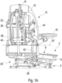
- Fig. 1A to Fig. 1C show in a perspective detailed view an embodiment of an electric wheelchair 2 according to the invention with upright function in different kinematic phases during an adjustment between a Fig. 1A shown seating position and one in Fig. 1C shown upright position.
- Fig. 1B corresponds to an intermediate position between the aforementioned positions.
- the wheelchair 2 has a base body 4, which is designed as a chassis that can be moved by means of an electric motor drive.
- the structure of a corresponding wheelchair is generally known to the person skilled in the art and is therefore not explained in more detail here.
- a seat part 6 with a seat surface 8 and a backrest part 10 with a backrest 12 are adjustable relative to each other and to the base body 4 (cf. Fig. 1 and Fig. 2 ) arranged.
- the seat part 6 and the backrest part 10 are relative to each other or to the base body 4 between the Fig. 1A illustrated seating position, in which the seat surface 8 is arranged approximately horizontally and the backrest 12 and the seat surface 8 are arranged approximately at right angles to each other, and the Fig. 1C shown upright position, in which the seat surface 8 and the backrest 12 together form an approximately vertical support surface.
- a corresponding upright function is generally known in electric wheelchairs and is not in itself the subject of the invention.
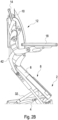
- the seat part 6 and the backrest part 10 are adjustable relative to each other and to the base body 4 between the sitting position and a lying position in which the backrest 12 and the seat 8 form an approximately horizontal lying surface.
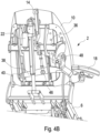
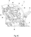
- Fig. 4 shows in different kinematic phases a corresponding adjustment between the sitting position and the lying position, whereby Fig. 4A the seating position and Fig. 4C represents the lying position.
- Fig. 4B represents an intermediate position between the aforementioned positions.
- an electromotive adjustment device with a first electromotive linear drive is provided, which is explained in more detail below.
- a second electromotive linear drive is provided for adjusting the backrest part 10 and the seat part 6 relative to each other or to the base body 4 between the sitting position and the upright position, which is also explained in more detail below.
- a headrest part 14 with a headrest 16 is connected to the backrest part 10 and serves to support the head of the user of the wheelchair 2.
- Fig. 9 shows the headrest 16 in different kinematic phases during an adjustment of the headrest 16 between a Fig. 9 A shown headrest seating position and one in Fig. 9 C shown headrest reclining position.
- Fig. 9 B shows an intermediate position between the headrest sitting position and the headrest reclining position.
- armrests are provided which are arranged on both sides of the seat 8 and of which only a right armrest 18 can be seen in the drawing (cf. Fig. 1 and Fig. 2 ).
- an electromotive adjustment device 20 with a first electromotive linear drive 22 (cf. Fig. 1A ) is provided.
- the first electromotive linear drive 22 is arranged and operatively connected between the backrest part 10 and the seat surface part 6 in such a way that when the linear drive 22 is actuated, the backrest part 10 is pivoted relative to the seat surface part 6 about a horizontal backrest part pivot axis 24 from the Fig. 1A shown seating position to the one in Fig. 1C
- the structure and functionality of the corresponding electromotive linear drives are generally known and are therefore not explained in detail here.
- Fig. 1A As shown in fig. 1, in the sitting position the backrest 12 and the seat 8 are arranged approximately at right angles to each other, while in the upright position the backrest 12 and the seat 8 form an approximately vertical continuous support surface, as shown in fig. Fig. 1C is shown.
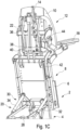
- a second electromotive linear drive 28 is provided (see in particular Fig. 1A ).
- the second electromotive linear drive 28 is arranged and operatively connected between the seat surface part 6 and the base body 4 in such a way that when the second electromotive linear drive 28 is actuated, the seat surface part 6 is moved between the Fig. 1A shown seating position, in which the seat surface 8 is arranged approximately horizontally, and the Fig. 1C shown upright position, in which the seat surface 8 is arranged approximately vertically and, as explained above, together with the backrest 12 forms an approximately vertical continuous support surface.
- a common control device is provided to control the first electromotive linear drive 22 and the second electromotive linear drive 28.
- the structure and functioning of a corresponding control device are generally known to those skilled in the art and are therefore not explained in more detail here.
- the common control device is also not shown in the drawing.
- the control device is designed and programmed in such a way that the adjustments to be carried out by the first electromotive linear drive 22 on the one hand and the second electromotive linear drive 28 on the other hand are carried out in a coordinated manner according to the position of the wheelchair 2 selected by the user (sitting position or upright position or lying position).
- Fig. 2 shows a partial view of the wheelchair 2 in the area of the backrest 12 and the seat 8 in different kinematic phases during an adjustment between the sitting position and the upright position, whereby the Fig. 2A the Fig. 1A , the Fig. 2B the Fig. 1B and the Fig. 2C the Fig. 1C corresponds.
- the second electromotive linear drive 28 is arranged in the longitudinal center plane of the wheelchair 2, as can be seen in particular from Fig. 1B is visible.
- the adjustment force applied by the linear drive 28 is introduced symmetrically. This is particularly advantageous when the adjustment is carried out against the weight of the body weight of a diverent user of the wheelchair 2.
- the return from the Fig. 1C shown upright position into the Fig. 1A The seating position shown occurs when the linear drive 22 is switched on under the force of the user's body weight.
- a gas pressure spring arrangement 30 with gas pressure springs 32, 34 is assigned to the second electromotive linear drive 28 and is connected in parallel to the second electromotive linear drive 28 in terms of drive technology (cf. in particular Fig. 1C ). Due to the parallel drive connection of the gas pressure springs 32, 34 to the second electromotive linear drive 28, the gas pressure springs 32, 34 support the latter during the adjustment movement between the sitting position and the upright position. This is particularly advantageous when the adjustment is carried out against the weight of the body weight of a diverent user of the wheelchair 2.
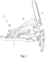
- Fig. 3 shows a view of a detail in the area of the connection between the seat part 6 and the base body 4, wherein in addition to the second electromotive linear drive 28, the gas pressure spring 34 of the gas pressure spring arrangement 30 can also be seen.
- mechanical coupling means are provided according to the invention, which in the illustrated embodiment are designed and connected to the headrest part 14 and the armrests such that when the backrest 12 is adjusted to the reclining position, the headrest 16 is adjusted relative to the backrest 12 from a headrest sitting position to a headrest reclining position and/or the armrests 18 are adjusted relative to the backrest 12 from an armrest sitting position to an armrest reclining position.
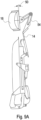
- the armrests 18 are connected to a common armrest part 36 (see for example Fig. 4A ) which is pivotably connected to the backrest part 10 about a horizontal armrest part pivot axis running transversely to the direction of travel of the wheelchair 2.
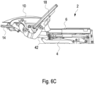
- the mechanical coupling means are designed such that in the armrest sitting position the support surfaces of the armrests 18 are arranged approximately at right angles to a support surface of the backrest 12 (cf. 4A and in particular Fig. 6 A) and in the armrest reclining position, the support surfaces of the armrests 18 form an obtuse angle of in particular approximately 135° with the support surface of the backrest 12 (cf. Fig. 4C and especially Fig. 6C ).
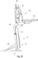
- the mechanical coupling means have an adjusting element which in the embodiment shown is formed by a pivot lever 38.
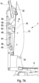
- the pivot lever 38 is arranged between the base body 4 and the backrest part 10 and is operatively connected such that the pivot lever 38 10 from the sitting position to the lying position from a first position (cf. Fig. 4A and Fig. 7A ) into a second position (cf. Fig. 4C and Fig. 7C).
- the pivot lever 38 is connected to the headrest part 14 and the armrest part 36 in such a way that when the pivot lever 38 is moved from its first position to its second position, the armrest part 36 is moved from the armrest sitting position to the armrest reclining position and the headrest part 14 is moved from the headrest sitting position to the headrest reclining position.
- the pivot lever 38 is pivotable about an adjustment element pivot axis 40 pointing in the direction of travel of the wheelchair 2 (cf. Fig. 4A ) with the backrest part 10.
- the free end of the pivot lever 38 facing away from the adjusting element pivot axis 40 is articulated to one end of a pivot lever coupling lever 42 (cf. Fig. 4A ), the other end of which is articulated to the base body 4 in such a way that when the backrest part 10 moves from the sitting position to the lying position, the pivot lever 38 moves from its first position (cf. Fig. 4A ) to its second position (cf. Fig. 4C ) is pivoted.
- the coupling of the pivot lever 38 to the base body 4 is effected by means of the pivot lever coupling lever 42 in such a way that when the backrest part 10 is adjusted from the sitting position to the lying position, the pivot lever 38 is forcibly pivoted from the first position to the second position.
- the armrest part 36 is connected to the pivot lever 38 via a rigid coupling rod 44.
- the coupling rod 44 performs a non-planar movement when the pivot lever 38 moves between its first position and its second position. For this reason, the coupling rod 44 is connected at one end to the pivot lever 38 and at the other end to the armrest part 36 via ball joints.
- the coupling rod 44 is connected at one end by means of a first ball joint 46 eccentrically to the adjusting member pivot axis 4 with the pivot lever 38 and at its other end connected to the armrest part 36 by means of a second ball joint 48 eccentrically to the armrest pivot axis.
- the pivot lever 38 is part of a first lever mechanism, which is a component of the mechanical coupling means according to the invention.
- the functioning of these mechanical coupling means is as follows: When adjusting the backrest part 10 from the position shown in Fig. 4A shown seating position to the one in Fig. 4C In the lying position shown by means of the first electromotive linear drive 22, the pivot lever 38 is moved out of its position in Fig. 4A and Fig. 6A shown first position in his in Fig. 4C and Fig. 6C Due to the mechanical coupling of the armrest part 36 to the pivot lever 38 by means of the coupling rod 44, the armrest part 36 is pivoted relative to the backrest part 10 in Fig.
- the mechanical coupling means provided according to the invention kinematically couple a movement of the armrest part 36 to a movement of the backrest part 10 from the sitting position to the lying position
- the corresponding adjustment movement of the armrest part 36 is a forced movement.
- the adjustment of the armrest part 36 from the armrest sitting position to the armrest lying position is thus carried out automatically by means of the first electromotive linear drive 22 when the backrest part 10 is adjusted to the lying position.
- a separate drive for the adjustment of the armrest part 36 relative to the backrest part 10 is not required.
- a corresponding operating process is not necessary for the user. In this way, the ergonomics of the wheelchair 2 and its adaptation to the anatomical conditions of a user.
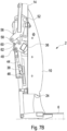
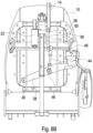
- Fig. 7 and Fig. 8 The kinematics of the components involved in the adjustment of the armrest part 36 are shown in the Fig. 7 and Fig. 8 further illustrated, whereby Fig. 7A and Fig. 8A the armrest seating position and Fig. 7B and Fig. 8B the armrest reclining position. Even if in the illustrated embodiment the adjustment of the armrest part 36 is coupled to the adjustment of the backrest part 10 in the manner described above, in Fig. 7 B and Fig. 8 B For illustration purposes, the backrest part 10 is still shown in its sitting position, while the components involved in the adjustment (pivot lever 38, coupling rod 44 and armrest part 36) are in Fig. 7B and Fig. 8B in the armrest reclining position. It can be seen that the armrest part 36 in Fig. 7 is swiveled clockwise from the armrest sitting position to the armrest lying position.
- the mechanical coupling means are designed in such a way that when the backrest 12 is adjusted to the reclining position, not only are the armrests 18 adjusted to the armrest reclining position, but rather the headrest part 14 is also adjusted from a headrest sitting position to a headrest reclining position.
- the headrest sitting position (cf. Fig. 9 A)
- the support surface of the headrest 18 together with the support surface of the backrest 12 forms an approximately horizontal support surface
- the support surface of the headrest 16 forms an obtuse angle with the support surface of the backrest 12 and the headrest 16 is thus inclined towards the user's head.
- Fig. 9 illustrated by the reference numerals 50.
- Fig. 9 A shows the headrest 16 in a slightly adjusted position towards the headrest reclining position, in which a reference surface of the headrest 16 coincides with a reference plane defined by the support surface of the backrest 12 and thus forms an angle of 0° with the reference plane.
- the reference surface of the headrest 16 forms an angle of approximately 3° with the horizontal reference plane.
- Fig. 9C shows the headrest 16 in the headrest reclining position, in which the reference surface of the headrest 16 forms an angle of approximately 25° with the reference plane, so that the support surface of the headrest 16 in the headrest reclining position forms an obtuse angle with the support surface of the backrest 12, i.e. the headrest is inclined towards the user's head.
- the headrest part 14 is pivotably mounted on the backrest part 10 about a horizontal headrest pivot axis 52 running transversely to the direction of travel of the wheelchair 2.
- the headrest pivot axis 52 runs in Fig. 7 A perpendicular to the drawing plane.
- the headrest part 14 has an adjustable and lockable holder 54 at its end facing away from the headrest pivot axis 52, at the free end of which the headrest 16 is arranged. By adjusting the holder accordingly, the basic position of the headrest 16 can be adjusted relative to the headrest part 14.
- the mechanical coupling means provided according to the invention are designed and connected to the headrest 16, namely in the illustrated embodiment to the headrest part 14, such that when the backrest 12 is adjusted to the reclining position, the headrest 16 is adjusted from its headrest sitting position to the headrest reclining position.
- the mechanical coupling means have a second lever mechanism which has a first lever 56 which is formed onto the headrest part 14 and is connected at its free end in an articulated manner about a first articulation axis 58 to a second lever 60 which is connected at its end facing away from the first articulation axis 58 in an articulated manner about a second articulation axis 62 to the armrest part 36 is connected eccentrically to its armrest pivot axis and spaced apart to the ball joint 48.
- the headrest 16 is tilted towards the user's feet.
- support in the area of the head is ergonomically improved and better adapted to the anatomical conditions of the user.
- it has been shown that such support is perceived as more comfortable than a continuous, almost horizontal lying surface.
- the headrest part 14 is mechanically coupled to the armrest part 36.
- the wheelchair 2 offers its user in the lying position an ergonomically improved support in the area of the head and arms that is better adapted to the anatomical conditions of the user. Due to the inventive arrangement of the second electromotive linear drive 28 in the longitudinal center plane of the wheelchair 2, the introduction of force into the backrest part 10 is improved when adjusting the same from the sitting position to the upright position. In this way, the uprighting function can be reliably maintained even if the adjustment is made against the weight of the body weight of a diverent user. In the same sense, the According to the invention, the gas pressure spring arrangement 30 is connected in parallel to the second electromotive linear drive 28.
Landscapes
- Health & Medical Sciences (AREA)
- Life Sciences & Earth Sciences (AREA)
- Animal Behavior & Ethology (AREA)
- General Health & Medical Sciences (AREA)
- Public Health (AREA)
- Veterinary Medicine (AREA)
- Otolaryngology (AREA)
- Seats For Vehicles (AREA)
- Chairs For Special Purposes, Such As Reclining Chairs (AREA)
Applications Claiming Priority (1)
| Application Number | Priority Date | Filing Date | Title |
|---|---|---|---|
| DE102018118570.7A DE102018118570A1 (de) | 2018-07-31 | 2018-07-31 | Elektrorollstuhl mit Aufrichtfunktion |
Publications (3)
| Publication Number | Publication Date |
|---|---|
| EP3603597A1 EP3603597A1 (de) | 2020-02-05 |
| EP3603597B1 true EP3603597B1 (de) | 2024-10-30 |
| EP3603597C0 EP3603597C0 (de) | 2024-10-30 |
Family
ID=67438508
Family Applications (1)
| Application Number | Title | Priority Date | Filing Date |
|---|---|---|---|
| EP19187751.3A Active EP3603597B1 (de) | 2018-07-31 | 2019-07-23 | Elektrorollstuhl mit aufrichtfunktion |
Country Status (4)
| Country | Link |
|---|---|
| EP (1) | EP3603597B1 (pl) |
| DE (1) | DE102018118570A1 (pl) |
| ES (1) | ES2999023T3 (pl) |
| PL (1) | PL3603597T3 (pl) |
Families Citing this family (3)
| Publication number | Priority date | Publication date | Assignee | Title |
|---|---|---|---|---|
| CN117098518A (zh) * | 2021-02-12 | 2023-11-21 | 普利维克公司 | 可固定到轮椅的尿液收集系统和相关方法 |
| CN113558884B (zh) * | 2021-07-20 | 2023-12-29 | 椅夫健康(厦门)智能科技有限公司 | 椅背与扶手协同动作的轮椅及其工作方法 |
| CN116492157A (zh) * | 2023-05-23 | 2023-07-28 | 南通智康达医疗科技有限公司 | 一种靠背倾斜角度可调节的电动轮椅 |
Family Cites Families (12)
| Publication number | Priority date | Publication date | Assignee | Title |
|---|---|---|---|---|
| US2690208A (en) * | 1950-07-20 | 1954-09-28 | Mary Francis | Chair for paralytics |
| DE2517418A1 (de) * | 1975-04-19 | 1976-11-04 | Wienand | Rollstuhl |
| SE449164B (sv) * | 1984-03-12 | 1987-04-13 | Henning Bergenwall | Mobel innefattande ett stativ, ett sete och ett relativt setet svengbart ryggstod |
| US5366036A (en) * | 1993-01-21 | 1994-11-22 | Perry Dale E | Power stand-up and reclining wheelchair |
| US6773032B2 (en) * | 1999-06-06 | 2004-08-10 | Don L. Redman | Ambulatory apparatus |
| FR2800589B1 (fr) * | 1999-11-10 | 2002-01-04 | Francis Tauzin | Fauteuil articule a usage medical, pour handicapes et pour le relaxation |
| US7585019B2 (en) * | 2006-12-04 | 2009-09-08 | Cycling & Health Tech Industry R & D Center | Seat reclining mechanism for power wheelchair |
| TW201029646A (en) * | 2009-02-13 | 2010-08-16 | Lloyd Linden Inc | Wheelchair device with assistance functions |
| FR2965716B1 (fr) * | 2010-10-12 | 2013-08-16 | Segula Matra Technologies | Fauteuil roulant equipe d'au moins un accoudoir |
| CZ2013859A3 (cs) * | 2013-11-07 | 2015-12-09 | MORAVSKĂť VĂťZKUM, s.r.o. | Robotické mobilní modifikovatelné lůžko |
| ES2626077T3 (es) * | 2014-05-19 | 2017-07-21 | Sunrise Medical Gmbh & Co. Kg | Conjunto de respaldo para una silla de ruedas con asiento reclinable |
| CZ2015801A3 (cs) * | 2015-11-10 | 2017-03-08 | Robotsystem, S.R.O. | Robotické mobilní a modifikovatelné lůžko s vertikalizací |
-
2018
- 2018-07-31 DE DE102018118570.7A patent/DE102018118570A1/de active Pending
-
2019
- 2019-07-23 ES ES19187751T patent/ES2999023T3/es active Active
- 2019-07-23 EP EP19187751.3A patent/EP3603597B1/de active Active
- 2019-07-23 PL PL19187751.3T patent/PL3603597T3/pl unknown
Also Published As
| Publication number | Publication date |
|---|---|
| DE102018118570A1 (de) | 2020-02-06 |
| PL3603597T3 (pl) | 2025-03-03 |
| ES2999023T3 (en) | 2025-02-24 |
| EP3603597C0 (de) | 2024-10-30 |
| EP3603597A1 (de) | 2020-02-05 |
Similar Documents
| Publication | Publication Date | Title |
|---|---|---|
| EP2374371B1 (de) | Sitzmöbel mit einem in eine Aufstehhilfsposition schwenkbaren Sitz | |
| EP1743612B1 (de) | Rollstuhl für körperbehinderte Personen | |
| EP1301106A1 (de) | Stuhl | |
| EP2403761B1 (de) | Fluggastsitzvorrichtung | |
| EP3965617B1 (de) | Sitzmöbel mit zweimotoriger wallaway-funktion | |
| DE19830418B4 (de) | Stuhlanordnung | |
| DE2141022B2 (de) | Zahnärztlicher Patientenstuhl mit neigbarer Rückenlehne und verstellbarem Sitz | |
| AT12867U1 (de) | Sitzmöbel | |
| EP2801293A1 (de) | Sitzmöbelstück und Beschlag hierfür | |
| EP3603597B1 (de) | Elektrorollstuhl mit aufrichtfunktion | |
| DE1404651C3 (de) | Verstellsessel mit ausschwenkbarer Beinstütze | |
| EP1850699A1 (de) | Möbel, insbesondere sitzmöbel | |
| EP2921078B1 (de) | Sitzmöbel mit einem Chassis und einem gegenüber dem Chassis schwenkbaren Fußteil | |
| DE202014011308U1 (de) | Sitzmöbel | |
| DE19801893A1 (de) | Kraftfahrzeugsitz mit verstellbarer Sitztiefe | |
| DE202020104509U1 (de) | Sitz- und Liegemöbel | |
| DE102020121375A1 (de) | Sitzträgerstruktur für einen Fahrzeugsitz | |
| DE69714910T2 (de) | Verstellvorrichtung | |
| DE102004047619A1 (de) | Sitzmöbel | |
| DE19700617C5 (de) | Sessel | |
| DE202009000731U1 (de) | Sitzmöbel | |
| EP4374741A1 (de) | Sitzmöbelstück | |
| DE19520429B4 (de) | Verstellbares Sitz-/Liegemöbel | |
| DE102016123962B4 (de) | Verstellbares Möbel | |
| DE3800756C2 (pl) |
Legal Events
| Date | Code | Title | Description |
|---|---|---|---|
| PUAI | Public reference made under article 153(3) epc to a published international application that has entered the european phase |
Free format text: ORIGINAL CODE: 0009012 |
|
| STAA | Information on the status of an ep patent application or granted ep patent |
Free format text: STATUS: THE APPLICATION HAS BEEN PUBLISHED |
|
| AK | Designated contracting states |
Kind code of ref document: A1 Designated state(s): AL AT BE BG CH CY CZ DE DK EE ES FI FR GB GR HR HU IE IS IT LI LT LU LV MC MK MT NL NO PL PT RO RS SE SI SK SM TR |
|
| AX | Request for extension of the european patent |
Extension state: BA ME |
|
| STAA | Information on the status of an ep patent application or granted ep patent |
Free format text: STATUS: REQUEST FOR EXAMINATION WAS MADE |
|
| 17P | Request for examination filed |
Effective date: 20200805 |
|
| RBV | Designated contracting states (corrected) |
Designated state(s): AL AT BE BG CH CY CZ DE DK EE ES FI FR GB GR HR HU IE IS IT LI LT LU LV MC MK MT NL NO PL PT RO RS SE SI SK SM TR |
|
| STAA | Information on the status of an ep patent application or granted ep patent |
Free format text: STATUS: EXAMINATION IS IN PROGRESS |
|
| 17Q | First examination report despatched |
Effective date: 20221109 |
|
| GRAP | Despatch of communication of intention to grant a patent |
Free format text: ORIGINAL CODE: EPIDOSNIGR1 |
|
| STAA | Information on the status of an ep patent application or granted ep patent |
Free format text: STATUS: GRANT OF PATENT IS INTENDED |
|
| RIC1 | Information provided on ipc code assigned before grant |
Ipc: A61G 5/04 20130101ALN20240524BHEP Ipc: A61G 5/14 20060101ALI20240524BHEP Ipc: A61G 5/12 20060101ALI20240524BHEP Ipc: A61G 5/00 20060101AFI20240524BHEP |
|
| INTG | Intention to grant announced |
Effective date: 20240610 |
|
| GRAS | Grant fee paid |
Free format text: ORIGINAL CODE: EPIDOSNIGR3 |
|
| GRAA | (expected) grant |
Free format text: ORIGINAL CODE: 0009210 |
|
| STAA | Information on the status of an ep patent application or granted ep patent |
Free format text: STATUS: THE PATENT HAS BEEN GRANTED |
|
| AK | Designated contracting states |
Kind code of ref document: B1 Designated state(s): AL AT BE BG CH CY CZ DE DK EE ES FI FR GB GR HR HU IE IS IT LI LT LU LV MC MK MT NL NO PL PT RO RS SE SI SK SM TR |
|
| REG | Reference to a national code |
Ref country code: GB Ref legal event code: FG4D Free format text: NOT ENGLISH |
|
| REG | Reference to a national code |
Ref country code: CH Ref legal event code: EP |
|
| REG | Reference to a national code |
Ref country code: IE Ref legal event code: FG4D Free format text: LANGUAGE OF EP DOCUMENT: GERMAN |
|
| REG | Reference to a national code |
Ref country code: DE Ref legal event code: R096 Ref document number: 502019012376 Country of ref document: DE |
|
| U01 | Request for unitary effect filed |
Effective date: 20241113 |
|
| U07 | Unitary effect registered |
Designated state(s): AT BE BG DE DK EE FI FR IT LT LU LV MT NL PT RO SE SI Effective date: 20241120 |
|
| REG | Reference to a national code |
Ref country code: GR Ref legal event code: EP Ref document number: 20240402905 Country of ref document: GR Effective date: 20250120 |
|
| REG | Reference to a national code |
Ref country code: ES Ref legal event code: FG2A Ref document number: 2999023 Country of ref document: ES Kind code of ref document: T3 Effective date: 20250224 |
|
| PG25 | Lapsed in a contracting state [announced via postgrant information from national office to epo] |
Ref country code: HR Free format text: LAPSE BECAUSE OF FAILURE TO SUBMIT A TRANSLATION OF THE DESCRIPTION OR TO PAY THE FEE WITHIN THE PRESCRIBED TIME-LIMIT Effective date: 20241030 Ref country code: IS Free format text: LAPSE BECAUSE OF FAILURE TO SUBMIT A TRANSLATION OF THE DESCRIPTION OR TO PAY THE FEE WITHIN THE PRESCRIBED TIME-LIMIT Effective date: 20250228 |
|
| PG25 | Lapsed in a contracting state [announced via postgrant information from national office to epo] |
Ref country code: RS Free format text: LAPSE BECAUSE OF FAILURE TO SUBMIT A TRANSLATION OF THE DESCRIPTION OR TO PAY THE FEE WITHIN THE PRESCRIBED TIME-LIMIT Effective date: 20250130 |
|
| PG25 | Lapsed in a contracting state [announced via postgrant information from national office to epo] |
Ref country code: SM Free format text: LAPSE BECAUSE OF FAILURE TO SUBMIT A TRANSLATION OF THE DESCRIPTION OR TO PAY THE FEE WITHIN THE PRESCRIBED TIME-LIMIT Effective date: 20241030 |
|
| PG25 | Lapsed in a contracting state [announced via postgrant information from national office to epo] |
Ref country code: SK Free format text: LAPSE BECAUSE OF FAILURE TO SUBMIT A TRANSLATION OF THE DESCRIPTION OR TO PAY THE FEE WITHIN THE PRESCRIBED TIME-LIMIT Effective date: 20241030 |
|
| PG25 | Lapsed in a contracting state [announced via postgrant information from national office to epo] |
Ref country code: CZ Free format text: LAPSE BECAUSE OF FAILURE TO SUBMIT A TRANSLATION OF THE DESCRIPTION OR TO PAY THE FEE WITHIN THE PRESCRIBED TIME-LIMIT Effective date: 20241030 |
|
| RAP4 | Party data changed (patent owner data changed or rights of a patent transferred) |
Owner name: MEYRA GMBH |
|
| U1H | Name or address of the proprietor changed after the registration of the unitary effect |
Owner name: MEYRA GMBH; DE |
|
| U20 | Renewal fee for the european patent with unitary effect paid |
Year of fee payment: 7 Effective date: 20250722 |
|
| PLBE | No opposition filed within time limit |
Free format text: ORIGINAL CODE: 0009261 |
|
| STAA | Information on the status of an ep patent application or granted ep patent |
Free format text: STATUS: NO OPPOSITION FILED WITHIN TIME LIMIT |
|
| 26N | No opposition filed |
Effective date: 20250731 |
|
| PGFP | Annual fee paid to national office [announced via postgrant information from national office to epo] |
Ref country code: ES Payment date: 20250819 Year of fee payment: 7 |
|
| PGFP | Annual fee paid to national office [announced via postgrant information from national office to epo] |
Ref country code: NO Payment date: 20250722 Year of fee payment: 7 Ref country code: GR Payment date: 20250721 Year of fee payment: 7 |
|
| PGFP | Annual fee paid to national office [announced via postgrant information from national office to epo] |
Ref country code: PL Payment date: 20250710 Year of fee payment: 7 Ref country code: TR Payment date: 20250718 Year of fee payment: 7 |
|
| PGFP | Annual fee paid to national office [announced via postgrant information from national office to epo] |
Ref country code: GB Payment date: 20250724 Year of fee payment: 7 |
|
| PGFP | Annual fee paid to national office [announced via postgrant information from national office to epo] |
Ref country code: CH Payment date: 20250801 Year of fee payment: 7 |