EP3597967A1 - Getriebesteuerungsvorrichtung für fahrzeug - Google Patents
Getriebesteuerungsvorrichtung für fahrzeug Download PDFInfo
- Publication number
- EP3597967A1 EP3597967A1 EP18768491.5A EP18768491A EP3597967A1 EP 3597967 A1 EP3597967 A1 EP 3597967A1 EP 18768491 A EP18768491 A EP 18768491A EP 3597967 A1 EP3597967 A1 EP 3597967A1
- Authority
- EP
- European Patent Office
- Prior art keywords
- vehicle
- shift
- speed
- vehicle speed
- setting unit
- Prior art date
- Legal status (The legal status is an assumption and is not a legal conclusion. Google has not performed a legal analysis and makes no representation as to the accuracy of the status listed.)
- Granted
Links
Images


Classifications
-
- F—MECHANICAL ENGINEERING; LIGHTING; HEATING; WEAPONS; BLASTING
- F16—ENGINEERING ELEMENTS AND UNITS; GENERAL MEASURES FOR PRODUCING AND MAINTAINING EFFECTIVE FUNCTIONING OF MACHINES OR INSTALLATIONS; THERMAL INSULATION IN GENERAL
- F16H—GEARING
- F16H59/00—Control inputs to control units of change-speed- or reversing-gearings for conveying rotary motion
- F16H59/48—Inputs being a function of acceleration
-
- F—MECHANICAL ENGINEERING; LIGHTING; HEATING; WEAPONS; BLASTING
- F16—ENGINEERING ELEMENTS AND UNITS; GENERAL MEASURES FOR PRODUCING AND MAINTAINING EFFECTIVE FUNCTIONING OF MACHINES OR INSTALLATIONS; THERMAL INSULATION IN GENERAL
- F16H—GEARING
- F16H59/00—Control inputs to control units of change-speed- or reversing-gearings for conveying rotary motion
- F16H59/36—Inputs being a function of speed
- F16H59/46—Inputs being a function of speed dependent on a comparison between speeds
-
- F—MECHANICAL ENGINEERING; LIGHTING; HEATING; WEAPONS; BLASTING
- F16—ENGINEERING ELEMENTS AND UNITS; GENERAL MEASURES FOR PRODUCING AND MAINTAINING EFFECTIVE FUNCTIONING OF MACHINES OR INSTALLATIONS; THERMAL INSULATION IN GENERAL
- F16H—GEARING
- F16H61/00—Control functions within control units of change-speed- or reversing-gearings for conveying rotary motion ; Control of exclusively fluid gearing, friction gearing, gearings with endless flexible members or other particular types of gearing
- F16H61/04—Smoothing ratio shift
-
- F—MECHANICAL ENGINEERING; LIGHTING; HEATING; WEAPONS; BLASTING
- F16—ENGINEERING ELEMENTS AND UNITS; GENERAL MEASURES FOR PRODUCING AND MAINTAINING EFFECTIVE FUNCTIONING OF MACHINES OR INSTALLATIONS; THERMAL INSULATION IN GENERAL
- F16H—GEARING
- F16H61/00—Control functions within control units of change-speed- or reversing-gearings for conveying rotary motion ; Control of exclusively fluid gearing, friction gearing, gearings with endless flexible members or other particular types of gearing
- F16H61/68—Control functions within control units of change-speed- or reversing-gearings for conveying rotary motion ; Control of exclusively fluid gearing, friction gearing, gearings with endless flexible members or other particular types of gearing specially adapted for stepped gearings
- F16H61/682—Control functions within control units of change-speed- or reversing-gearings for conveying rotary motion ; Control of exclusively fluid gearing, friction gearing, gearings with endless flexible members or other particular types of gearing specially adapted for stepped gearings with interruption of drive
-
- F—MECHANICAL ENGINEERING; LIGHTING; HEATING; WEAPONS; BLASTING
- F16—ENGINEERING ELEMENTS AND UNITS; GENERAL MEASURES FOR PRODUCING AND MAINTAINING EFFECTIVE FUNCTIONING OF MACHINES OR INSTALLATIONS; THERMAL INSULATION IN GENERAL
- F16H—GEARING
- F16H59/00—Control inputs to control units of change-speed- or reversing-gearings for conveying rotary motion
- F16H59/60—Inputs being a function of ambient conditions
- F16H59/66—Road conditions, e.g. slope, slippery
- F16H2059/663—Road slope
-
- F—MECHANICAL ENGINEERING; LIGHTING; HEATING; WEAPONS; BLASTING
- F16—ENGINEERING ELEMENTS AND UNITS; GENERAL MEASURES FOR PRODUCING AND MAINTAINING EFFECTIVE FUNCTIONING OF MACHINES OR INSTALLATIONS; THERMAL INSULATION IN GENERAL
- F16H—GEARING
- F16H61/00—Control functions within control units of change-speed- or reversing-gearings for conveying rotary motion ; Control of exclusively fluid gearing, friction gearing, gearings with endless flexible members or other particular types of gearing
- F16H61/02—Control functions within control units of change-speed- or reversing-gearings for conveying rotary motion ; Control of exclusively fluid gearing, friction gearing, gearings with endless flexible members or other particular types of gearing characterised by the signals used
- F16H61/0202—Control functions within control units of change-speed- or reversing-gearings for conveying rotary motion ; Control of exclusively fluid gearing, friction gearing, gearings with endless flexible members or other particular types of gearing characterised by the signals used the signals being electric
- F16H61/0204—Control functions within control units of change-speed- or reversing-gearings for conveying rotary motion ; Control of exclusively fluid gearing, friction gearing, gearings with endless flexible members or other particular types of gearing characterised by the signals used the signals being electric for gearshift control, e.g. control functions for performing shifting or generation of shift signal
- F16H61/0213—Control functions within control units of change-speed- or reversing-gearings for conveying rotary motion ; Control of exclusively fluid gearing, friction gearing, gearings with endless flexible members or other particular types of gearing characterised by the signals used the signals being electric for gearshift control, e.g. control functions for performing shifting or generation of shift signal characterised by the method for generating shift signals
- F16H2061/0227—Shift map selection, i.e. methods for controlling selection between different shift maps, e.g. to initiate switch to a map for up-hill driving
-
- F—MECHANICAL ENGINEERING; LIGHTING; HEATING; WEAPONS; BLASTING
- F16—ENGINEERING ELEMENTS AND UNITS; GENERAL MEASURES FOR PRODUCING AND MAINTAINING EFFECTIVE FUNCTIONING OF MACHINES OR INSTALLATIONS; THERMAL INSULATION IN GENERAL
- F16H—GEARING
- F16H61/00—Control functions within control units of change-speed- or reversing-gearings for conveying rotary motion ; Control of exclusively fluid gearing, friction gearing, gearings with endless flexible members or other particular types of gearing
- F16H61/02—Control functions within control units of change-speed- or reversing-gearings for conveying rotary motion ; Control of exclusively fluid gearing, friction gearing, gearings with endless flexible members or other particular types of gearing characterised by the signals used
- F16H61/0202—Control functions within control units of change-speed- or reversing-gearings for conveying rotary motion ; Control of exclusively fluid gearing, friction gearing, gearings with endless flexible members or other particular types of gearing characterised by the signals used the signals being electric
- F16H61/0204—Control functions within control units of change-speed- or reversing-gearings for conveying rotary motion ; Control of exclusively fluid gearing, friction gearing, gearings with endless flexible members or other particular types of gearing characterised by the signals used the signals being electric for gearshift control, e.g. control functions for performing shifting or generation of shift signal
- F16H61/0213—Control functions within control units of change-speed- or reversing-gearings for conveying rotary motion ; Control of exclusively fluid gearing, friction gearing, gearings with endless flexible members or other particular types of gearing characterised by the signals used the signals being electric for gearshift control, e.g. control functions for performing shifting or generation of shift signal characterised by the method for generating shift signals
- F16H2061/0234—Adapting the ratios to special vehicle conditions
-
- F—MECHANICAL ENGINEERING; LIGHTING; HEATING; WEAPONS; BLASTING
- F16—ENGINEERING ELEMENTS AND UNITS; GENERAL MEASURES FOR PRODUCING AND MAINTAINING EFFECTIVE FUNCTIONING OF MACHINES OR INSTALLATIONS; THERMAL INSULATION IN GENERAL
- F16H—GEARING
- F16H61/00—Control functions within control units of change-speed- or reversing-gearings for conveying rotary motion ; Control of exclusively fluid gearing, friction gearing, gearings with endless flexible members or other particular types of gearing
- F16H61/16—Inhibiting or initiating shift during unfavourable conditions , e.g. preventing forward-reverse shift at high vehicle speed, preventing engine overspeed
- F16H2061/163—Holding the gear for delaying gear shifts under unfavorable conditions, e.g. during cornering
-
- F—MECHANICAL ENGINEERING; LIGHTING; HEATING; WEAPONS; BLASTING
- F16—ENGINEERING ELEMENTS AND UNITS; GENERAL MEASURES FOR PRODUCING AND MAINTAINING EFFECTIVE FUNCTIONING OF MACHINES OR INSTALLATIONS; THERMAL INSULATION IN GENERAL
- F16H—GEARING
- F16H59/00—Control inputs to control units of change-speed- or reversing-gearings for conveying rotary motion
- F16H59/36—Inputs being a function of speed
- F16H59/44—Inputs being a function of speed dependent on machine speed, e.g. the vehicle speed
-
- F—MECHANICAL ENGINEERING; LIGHTING; HEATING; WEAPONS; BLASTING
- F16—ENGINEERING ELEMENTS AND UNITS; GENERAL MEASURES FOR PRODUCING AND MAINTAINING EFFECTIVE FUNCTIONING OF MACHINES OR INSTALLATIONS; THERMAL INSULATION IN GENERAL
- F16H—GEARING
- F16H59/00—Control inputs to control units of change-speed- or reversing-gearings for conveying rotary motion
- F16H59/60—Inputs being a function of ambient conditions
-
- F—MECHANICAL ENGINEERING; LIGHTING; HEATING; WEAPONS; BLASTING
- F16—ENGINEERING ELEMENTS AND UNITS; GENERAL MEASURES FOR PRODUCING AND MAINTAINING EFFECTIVE FUNCTIONING OF MACHINES OR INSTALLATIONS; THERMAL INSULATION IN GENERAL
- F16H—GEARING
- F16H61/00—Control functions within control units of change-speed- or reversing-gearings for conveying rotary motion ; Control of exclusively fluid gearing, friction gearing, gearings with endless flexible members or other particular types of gearing
- F16H61/16—Inhibiting or initiating shift during unfavourable conditions , e.g. preventing forward-reverse shift at high vehicle speed, preventing engine overspeed
Definitions
- the present invention relates to a transmission control device for a vehicle.
- a clutch In a vehicle including a multi-stage transmission such as an automatic transmission (AT) and an automated manual transmission (AMT), if a clutch is released according to shift-up during acceleration by depression of an accelerator, a time for which an engine torque is not transmitted to the tire side occurs (hereinafter, referred to as a torque interruption).
- a torque interruption a time for which an engine torque is not transmitted to the tire side occurs.
- torque interruption shock a driver who drives the vehicle receives an impact due to the sudden torque interruption
- the driver By reducing a depression amount of the accelerator immediately before the shift-up, the driver (or the automated driving ECU) can reduce the torque interruption shock. However, a time for which the vehicle cannot be accelerated further increases.
- a method in which, even if the driver keeps depressing the accelerator, the ECU performs control to temporarily loosen a throttle for adjusting an amount of air to be sent to an engine, thereby mitigating the torque interruption shock at the time of the shift-up (performing control for releasing the clutch after loosening the throttle little by little, before releasing the clutch) is also considered.
- the torque interruption shock can be mitigated.
- the torque interruption occurs, and as a result of performing the control for loosening the throttle by the ECU, the time for which the vehicle cannot be accelerated rather increases.
- PTL 2 technology for performing shift control of the multi-stage transmission on the basis of a relative speed between an own vehicle and a preceding vehicle, an inter-vehicle distance, and a target inter-vehicle distance is disclosed (PTL 2).
- the present invention has been made in view of the above problems and an object thereof is to provide a transmission control device for a vehicle capable of changing a threshold of a shift map for determining shift-up, thereby preventing occurrence of the shift-up during depression of an accelerator and preventing occurrence of a torque interruption.
- a transmission control device for a vehicle including a control unit which automatically performs shift control for switching a plurality of gears of a multi-stage transmission for shift-up or shift-down.
- the control unit has a shift threshold setting unit which sets a shift threshold to be used for the shift control, on the basis of an operation plan or a surrounding state of the vehicle, and the shift threshold setting unit sets the shift threshold to perform the shift control on the multi-stage transmission so as not to perform the shift-up of the multi-stage transmission during acceleration of the vehicle.
- the shift threshold setting unit sets the shift threshold, on the basis of an upper limit vehicle speed of the vehicle to be predicted during an acceleration period until the vehicle starts to accelerate and then reduces an acceleration amount.
- a measurement unit which measures the presence or absence of other vehicle located in front of the vehicle and a distance and/or a relative speed between the vehicle and other vehicle is included. The presence or absence of other vehicle and the distance or the relative speed between the vehicle and other vehicle, measured by the measurement unit, are used to determine the surrounding state.
- the present invention since occurrence of a torque interruption shock in a multi-stage transmission is prevented, it is not necessary for a driver to perform a complicated operation such as temporarily loosening an accelerator near shift timing during acceleration of a vehicle. Therefore, for the driver, drivability of the vehicle is improved.
- a vehicle 1 including an AMT will be described.
- the present invention is not limited thereto, and a vehicle including a transmission having a multi-stage transmission may be used and a vehicle including an AT having a multi-stage transmission may be used.
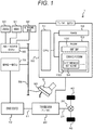
- FIG. 1 is a block diagram illustrating an entire structure of the vehicle 1 according to the present invention.
- a transmission (T/M) 20 is connected to an output shaft 11 of a drive source 10 and a rotation number of the output shaft 11 is shifted to a predetermined rotation number by the transmission 20.
- the rotation number of the output shaft 11 shifted by the transmission 20 is transmitted to a propeller shaft 21 to be the input side of a differential gear 30 and is transmitted to left and right tires 40 and 40 via the differential gear 30.
- the drive source 10 has a configuration generally used as a drive source of the vehicle, such as an internal combustion engine such as an engine, a motor, and a combination of the internal combustion engine and the motor.
- an internal combustion engine such as an engine, a motor, and a combination of the internal combustion engine and the motor.
- the transmission 20 is a multi-stage transmission with a plurality of gears having different numbers of teeth. By selecting an optimum gear from the plurality of gears, the transmission 20 converts the rotation number of the drive source 10 (output shaft 11) into a desired rotation number or changes the rotation direction and transmits it.
- the transmission 20 has five shift gears of a first gear, a second gear, a third gear, a fourth gear, and a fifth gear not shown in the drawing.
- the shift gears are sequentially switched from the first gear to the fifth gear, so that it is possible to shift the vehicle 1 from low-speed traveling to high-speed traveling.
- any shift gear of the first to fifth gears is appropriately switched, so that acceleration or deceleration of the vehicle 1 is smoothly performed.
- Switching of the shift gear is performed by a T/M-ECU 50.
- the T/M-ECU 50 automatically performs switching of each shift gear, on the basis of a shift map 100 (refer to FIG. 2 ) having a shift threshold defined by a relation between a speed of the vehicle (vehicle speed) and a depression amount of an accelerator 95 (accelerator opening).
- the T/M-ECU 50 has a CPU 51, a RAM 52 for temporarily storing data processed by the CPU 51, and a ROM 53 for storing the shift map 100 and a control program 150 executed by the CPU 51.
- the control program 150 includes a shift threshold setting unit 54.
- the T/M-ECU 50 constitutes a control unit of the present invention.
- the central processing unit (CPU) 51 is a so-called microprocessor, and reads and executes the control program 150 stored in the ROM 53 to perform processing for controlling switching of the shift gear of the transmission 20.
- the random access memory (RAM) 52 is a volatile memory, and has a work area in which data processed by the CPU 51 is temporarily stored so as to be readable and writable.
- the data processed by the CPU 51 is temporarily stored in the RAM 52, and the stored data is read by the CPU 51 and is used again for processing by the CPU 51.
- the read only memory (ROM) 53 is a non-volatile memory, and the control program 150 necessary for the T/M-ECU 50 to execute control for switching the shift gear of the transmission 20 is stored in the ROM 53.
- the control program 150 is read and executed by the CPU 51.
- the shift map 100 used by the CPU 51 to determine timing at which the shift gear of the transmission 20 is switched is stored in the ROM 53.
- the shift map 100 is read by the CPU 51 and is temporarily stored in the RAM 52.
- the shift threshold setting unit 54 included in the control program 150 calculates a shift threshold used in the shift map 100, on the basis of a surrounding state of the vehicle 1 or an operation plan preset in the case of automated driving, and resets (changes) the shift threshold of the shift map 100 temporarily stored in the RAM 52 to the calculated new shift threshold.
- the AD/ADAS-ECU 60 is an ECU of a system for automatically driving a vehicle or assisting driving by a driver D, and is generally called an automated driving/advanced driver assistance system.
- the AD/ADAS-ECU 60 is connected to a camera (stereo camera) 90 for photographing the surroundings of the vehicle 1, a radar 91 for detecting an object around the vehicle 1, and an ultrasonic wave 92.
- a camera stereo camera
- radar radar
- ultrasonic wave 92 ultrasonic wave
- the AD/ADAS-ECU 60 determines the surrounding state of the vehicle 1, on the basis of information obtained by the camera 90, the radar 91, and the ultrasonic wave 92.
- the AD/ADAS-ECU 60 determines whether or not there is a preceding vehicle Cf in front of the vehicle 1, on the basis of a photographed image of the camera 90 which has photographed the front of the vehicle 1 (own vehicle). When there is the preceding vehicle Cf, the AD/ADAS-ECU 60 calculates a distance S(t) and a relative speed Vr(t) between the preceding vehicle Cf and the vehicle 1. Further, in the case of the automated driving of the vehicle, an immediate operation plan is calculated on the basis of the surrounding state. At this time, an immediate vehicle speed plan V(t) of a time and a vehicle speed is calculated as a part of the operation plan.
- Information of the distance S(t) and the relative speed Vr(t) between the preceding vehicle Cf and the vehicle 1, calculated by the AD/ADAS-ECU 60, or the immediate vehicle speed plan V(t) is transmitted to the T/M-ECU 50 via an in-vehicle communication path 98 such as a controller area network (CAN) and is used for calculation of the shift threshold in the shift threshold setting unit 54.
- an in-vehicle communication path 98 such as a controller area network (CAN)
- An ENG-ECU 70 is a control device that controls the drive source 10.
- the ENG-ECU 70 has a CPU, a RAM, a ROM, and the like not shown in the drawing.
- the CPU executes a control program stored in the ROM not shown in the drawing, so that processing for controlling the drive source 10 is performed.
- the ENG-ECU 70 controls an opening (throttle opening) of a throttle to adjust an amount of air sent to the drive source 10, on the basis of a required drive force or a required rotation number transmitted from the T/M-ECU 50 via the in-vehicle communication path 98.
- an output (rotation number of the output shaft 11) of the drive source 10 is controlled.
- a vehicle speed V of the vehicle 1 is adjusted.
- the T/M-ECU 50 constitutes a transmission control device of the present invention.
- FIG. 2 is a diagram illustrating the shift map 100.
- the T/M-ECU 50 (ROM 53) has shift maps for shift-up and shift-down, respectively, and uses each shift map to determine timing of switching (shift change) of the shift gears (first gear to fifth gear).
- shift map 100 for the shift-up will be described below and the description of the shift map for the shift-down will be omitted.
- the shift map 100 in which a vehicle speed V of the vehicle 1 is represented by a horizontal axis to be one axis and a depression amount (accelerator opening A) of the accelerator 95 by the driver D is represented by a vertical axis to be the other axis is shown.
- the vertical axis of the shift map 100 may represent the throttle opening indicating the opening of the throttle.
- a plurality of shift thresholds defined by the vehicle speed V and the accelerator opening A are set.
- a 1-2 shift threshold 101 defining switching timing from the first gear to the second gear
- a 2-3 shift threshold 102 defining switching timing from the second gear to the third gear
- a 3-4 shift threshold 103 defining switching timing from the third gear to the fourth gear
- a 4-5 shift threshold 104 defining switching timing from the fourth gear to the fifth gear
- the T/M-ECU 50 performs control for switching the shift gear of the transmission 20 from the first gear to the second gear and instructs the ENG-ECU 70 to output the drive force or the rotation number according to the transient state at the time of shifting and the gear after shifting. In this way, the shift-up of the transmission 20 is performed.
- the T/M-ECU 50 When the vehicle speed V of the vehicle 1 exceeds each of the 2-3 shift threshold 102, the 3-4 shift threshold 103, and the 4-5 shift threshold 104, the T/M-ECU 50 performs control for switching the shift gear from the second gear to the third gear, from the third gear to the fourth gear, and from the fourth gear to the fifth gear, respectively, so that the shift-up of the transmission 20 is sequentially performed.
- the shift gear of the transmission 20 is switched from the second gear to the third gear.
- a time during which the torque of the drive source 10 is not transmitted to the side of the tires 40 and 40 from the clutch release to the reconnection occurs and a so-called torque interruption state occurs. Further, at the time of entering the torque interruption state, an impact (torque interruption shock) occurs due to a change from a state where the torque is applied to a state where the torque is not applied suddenly.
- the shift threshold (2-3 shift threshold 102) defining the timing at which the second gear of the transmission 20 is switched to the third gear is changed to a position shifted to the right side in the drawing as compared with an upper limit vehicle speed V(tg) of the vehicle 1 predicted from the accelerator opening A1 at the current shift position (changed 2-3 shift threshold 102A: broken line in the drawing).
- the changed 2-3 shift threshold 102A is positioned on the right side in the drawing as compared with the upper limit vehicle speed V(tg) of the vehicle 1 predicted at the current shift position.
- the vehicle 1 reaches the upper limit vehicle speed V(tg) before switching (shift-up) from the second gear to the third gear.
- the driver D performs an operation of loosening the accelerator 95 (the accelerator opening A decreases), on the basis of that the vehicle speed of the vehicle 1 has exceeded the upper limit vehicle speed V(tg).
- the changed shift threshold (for example, the 2-3 shift threshold 102A) is set to pass through the coordinates (V(tg) + ⁇ , A1 - ⁇ ) of (V(tg) + ⁇ ) larger than the predicted upper limit vehicle speed V(tg) by a margin amount ⁇ and (A1 - ⁇ ) smaller than the current accelerator opening A1 by a margin amount ⁇ .
- the shift-up is not performed during the acceleration period during which the vehicle 1 accelerates up to the upper limit vehicle speed V(tg) predicted at the shift position, in a state of the accelerator opening A1.
- the vehicle speed V of the vehicle 1 exceeds the changed 2-3 shift threshold 102A, so that switching (shift-up) from the second gear to the third gear is performed at timing when the driver D loosens the accelerator 95.
- loosening of the accelerator 95 by the driver D means that the driver D attempts to reduce the acceleration of the vehicle 1. Therefore, by performing the shift-up of the vehicle 1 at this timing, a sense of discomfort when the acceleration is not performed temporarily due to the torque interruption is reduced, and the torque interruption shock is also reduced.
- a maximum vehicle speed Vmax is set for each shift threshold, and each shift threshold is set so as not to exceed each maximum vehicle speed Vmax.
- the changed 2-3 shift threshold 102A is set so as not to exceed the maximum vehicle speed Vmax set by the 2-3 shift threshold 102A (in the drawing, the 2-3 shift threshold 102A is located at the left side of the maximum vehicle speed Vmax).
- the upper limit vehicle speed V(tg) of the vehicle 1 can be represented by the following formula.
- V tg a 2 ⁇ a 1 ⁇ Vf + a 2 ⁇ a 1 ⁇ a 2 ⁇ Vf 2 ⁇ 4 Vf ⁇ V O + 2 V O 2 ⁇ 2 ⁇ a 1 S O ⁇ Vf ⁇ tb + ⁇ a 2 ⁇ a 1
- the upper limit vehicle speed V(tg) represented by the above formula 1 is calculated on the basis of the distance S(t) or the relative speed Vr(t) between the preceding vehicle Cf and the vehicle 1, measured using the camera 90, the radar 91, and the ultrasonic wave 92 mounted on the vehicle 1. Further, when the vehicle 1 is driven automatically, the upper limit vehicle speed V(tg) is calculated on the basis of the operation plan (including the vehicle speed) of the vehicle calculated by the automated driving ECU.
- the upper limit vehicle speed V(tg) can be obtained by calculating the upper limit value of the vehicle speed predicted during the acceleration period from the start of the acceleration of the vehicle 1 to the reduction of the acceleration amount.
- the vehicle speed of the preceding vehicle Cf is constant at Vf and the depression amount of the accelerator 95 by the driver D is constant until the vehicle catches up with the preceding vehicle Cf.
- the inter-vehicle distance between the preceding vehicle Cf and the vehicle 1 (own vehicle) is set to S(t)
- the target inter-vehicle distance Sb is a distance at which the vehicle 1 can stop without colliding with the preceding vehicle Cf, when the vehicle 1 stops by sudden braking according to a stop of the preceding vehicle Cf by sudden braking, in a state where the vehicle 1 has caught up with the preceding vehicle Cf (both vehicles have the vehicle speed of Vf).
- tb is considered to be about 0.75 seconds when the driver D of the vehicle 1 views a brake lamp of the preceding vehicle Cf and depresses the brake.
- tb can be decreased.
- tb may be set to a large value.
- the running resistance R can be represented by the following formula 3.
- R V 1 2 ⁇ ⁇ CdAV 2 + ⁇ ⁇ Mg
- An upper limit is determined by a constant drive force line (a graph plotting a maximum drive force for each vehicle speed with a vehicle speed on a horizontal axis and a drive force on a vertical axis for each shift position) for each vehicle type.
- FIG. 3 is a diagram illustrating a method of deriving the upper limit vehicle speed V(tg).
- a vehicle speed change (solid line in the drawing) when the vehicle 1 catches up with the preceding vehicle Cf is approximated by a straight line (one-dotted chain line in the drawing), and its vertex is used as an approximate solution of the upper limit vehicle speed V (tg) .
- the inter-vehicle distance reduced until the vehicle 1 catches up with the preceding vehicle Cf and the vehicle speed becomes Vf is represented by a difference between an area of a region K1 (leftward oblique hatching in FIG. 3 ) and an area of a region K2 (rightward oblique hatching in the drawing).
- Vf V(0) - Vr(0) can be obtained.
- FIG. 4 is a diagram illustrating the operation (vehicle speed change) of the vehicle in the case of using the shift map 100 of the present invention, together with the operation (vehicle speed change) of the vehicle in the case of using the conventional shift map.
- the second gear is switched to the third gear before the vehicle (own vehicle) is accelerated and reaches the vehicle speed Vf of the preceding vehicle Cf. Since the vehicle (own vehicle) reaches the vehicle speed Vf (upper limit vehicle speed V(tg)) of the preceding vehicle Cf after the shift gear is switched to the third gear, the driver D loosens the accelerator.
- the driver D feels that it is not possible to obtain expected acceleration according to the depression amount of the accelerator 95.
- the operation plan of the automated driving may be disturbed.
- the second gear is switched to the third gear.
- the torque interruption occurs in a state where the accelerator opening of the vehicle 1 decreases from A1 to A2, so that the torque interruption shock decreases as compared with the case where the torque interruption occurs in a state of A1 where the accelerator opening is large. Further, in the vehicle 1, it is possible to obtain expected acceleration according to the depression amount of the accelerator 95 by the driver D.
- the drivability of the vehicle by the driver D can be increased, and when the vehicle 1 is driven automatically, the operation plan is not disturbed.
- a shift map having a shift threshold obtained by previously shifting the shift threshold at each shift position to the high speed side in consideration of the torque interruption shock may be stored in the ROM 53.
- a plurality of shift maps having different shift thresholds according to the surrounding state or the operation plan may be stored in the ROM 53, a shift map having an appropriate shift threshold may be read and used according to the surrounding state or the operation plan, and the shift threshold may be changed as described above on the basis of the surrounding state or the operation plan, with respect to the plurality of shift maps.
- the shift map can be adjusted more finely according to the surrounding state or the operation plan, and the drivability of the driver can be improved and the degree of freedom of the operation plan can be increased.
- the shift-up of the transmission 20 is performed in a range of vehicle speeds equal to or lower than the maximum vehicle speed Vmax set to each shift position. Therefore, it is possible to prevent the noise, the vibration, or the deterioration of the fuel efficiency of the vehicle 1 (drive source 10) due to the vehicle 1 exceeding the maximum vehicle speed Vmax set to each shift position (maximum vehicle speed set in a range that does not enter an engine overspeed region at each shift position).
Landscapes
- Engineering & Computer Science (AREA)
- General Engineering & Computer Science (AREA)
- Mechanical Engineering (AREA)
- Control Of Transmission Device (AREA)
Applications Claiming Priority (2)
| Application Number | Priority Date | Filing Date | Title |
|---|---|---|---|
| JP2017049434 | 2017-03-15 | ||
| PCT/JP2018/007433 WO2018168459A1 (ja) | 2017-03-15 | 2018-02-28 | 車両の変速機制御装置 |
Publications (3)
| Publication Number | Publication Date |
|---|---|
| EP3597967A1 true EP3597967A1 (de) | 2020-01-22 |
| EP3597967A4 EP3597967A4 (de) | 2020-12-23 |
| EP3597967B1 EP3597967B1 (de) | 2022-03-30 |
Family
ID=63522958
Family Applications (1)
| Application Number | Title | Priority Date | Filing Date |
|---|---|---|---|
| EP18768491.5A Active EP3597967B1 (de) | 2017-03-15 | 2018-02-28 | Getriebesteuerungsvorrichtung für fahrzeug |
Country Status (5)
| Country | Link |
|---|---|
| US (1) | US11041563B2 (de) |
| EP (1) | EP3597967B1 (de) |
| JP (1) | JP6738958B2 (de) |
| CN (1) | CN110382924B (de) |
| WO (1) | WO2018168459A1 (de) |
Cited By (1)
| Publication number | Priority date | Publication date | Assignee | Title |
|---|---|---|---|---|
| US11420026B2 (en) | 2015-04-10 | 2022-08-23 | Edwards Lifesciences Corporation | Expandable sheath |
Families Citing this family (3)
| Publication number | Priority date | Publication date | Assignee | Title |
|---|---|---|---|---|
| EP3279522A1 (de) * | 2016-08-04 | 2018-02-07 | DANA ITALIA S.r.l. | Steuergerät zur steuerung eines fahrzeugantriebsstrangs und verfahren zur kalibrierung eines fahrzeugantriebsstrangsteuergeräts |
| JP7000378B2 (ja) * | 2019-04-26 | 2022-01-19 | ファナック株式会社 | 無人搬送ロボットシステム |
| CN114228719B (zh) * | 2022-02-11 | 2024-05-07 | 同济大学 | 车辆辅助制动方法、电子设备及存储介质 |
Family Cites Families (22)
| Publication number | Priority date | Publication date | Assignee | Title |
|---|---|---|---|---|
| JPH0293163A (ja) * | 1988-09-30 | 1990-04-03 | Diesel Kiki Co Ltd | 車輌用自動変速装置 |
| GB9602731D0 (en) * | 1996-02-10 | 1996-04-10 | Ap Kongsberg Holdings Ltd | Transmission control systems |
| JP3650673B2 (ja) * | 1996-04-30 | 2005-05-25 | 本田技研工業株式会社 | 車両用内燃エンジンの制御装置 |
| US5738605A (en) * | 1996-06-28 | 1998-04-14 | Chrysler Corporation | Anti-hunt strategy for an automatic transmission |
| JPH10141496A (ja) * | 1996-10-25 | 1998-05-29 | Aqueous Res:Kk | 車両制御装置 |
| JP2008081118A (ja) | 1997-04-25 | 2008-04-10 | Hitachi Ltd | 自動車の制御装置及び制御方法 |
| US6098004A (en) * | 1998-06-04 | 2000-08-01 | Ford Global Technologies, Inc. | Preventing gear hunting in an automatic transmission for a motor vehicle |
| DE19849059A1 (de) * | 1998-10-24 | 2000-04-27 | Zahnradfabrik Friedrichshafen | Verfahren zur Steuerung eines Automatgetriebes eines Kraftfahrzeuges bei einer spontanen Gas-/Pedalrücknahme |
| JP2001324004A (ja) | 2000-05-18 | 2001-11-22 | Mitsubishi Motors Corp | 機械式自動変速機の変速制御装置 |
| JP3770056B2 (ja) | 2000-06-01 | 2006-04-26 | 日産自動車株式会社 | 自動変速機の変速ショック軽減装置 |
| JP2002156036A (ja) | 2000-11-20 | 2002-05-31 | Aisin Seiki Co Ltd | 車両用自動変速装置 |
| JP3994668B2 (ja) | 2001-01-30 | 2007-10-24 | スズキ株式会社 | 自動変速機の変速制御装置 |
| JP2003329123A (ja) * | 2002-05-13 | 2003-11-19 | Denso Corp | 車両制御装置 |
| JP2005113967A (ja) * | 2003-10-03 | 2005-04-28 | Toyota Motor Corp | 車両用自動変速機の変速制御装置 |
| JP2006132663A (ja) * | 2004-11-05 | 2006-05-25 | Mitsubishi Fuso Truck & Bus Corp | 機械式自動変速制御装置 |
| DE102005031764A1 (de) * | 2005-07-07 | 2007-01-18 | Zf Friedrichshafen Ag | Verfahren zum Steuern eines Antriebsstranges eines Fahrzeugs mit einer Antriebsmaschine und mit einem Getriebe |
| US7584041B2 (en) * | 2008-01-29 | 2009-09-01 | Gm Global Technology Operations, Inc. | Wheel slippage detection for drivetrain control |
| JP2010112502A (ja) | 2008-11-07 | 2010-05-20 | Toyota Motor Corp | 車両用変速制御装置 |
| JP5982766B2 (ja) * | 2011-09-26 | 2016-08-31 | 日産自動車株式会社 | 自動変速機の変速制御装置 |
| US8855877B2 (en) * | 2011-10-31 | 2014-10-07 | Ford Global Technologies, Llc | Controlling gearshifting to prevent powertrain hunting |
| US8880308B2 (en) * | 2011-12-12 | 2014-11-04 | Chrysler Group Llc | Methods and system for using vehicle longitudinal acceleration for transmission control |
| CN105221732A (zh) * | 2015-10-13 | 2016-01-06 | 哈尔滨东安汽车发动机制造有限公司 | 一种交通拥堵状况下汽车变速器的控制方法 |
-
2018
- 2018-02-28 JP JP2019505856A patent/JP6738958B2/ja active Active
- 2018-02-28 CN CN201880006201.9A patent/CN110382924B/zh active Active
- 2018-02-28 US US16/463,063 patent/US11041563B2/en active Active
- 2018-02-28 WO PCT/JP2018/007433 patent/WO2018168459A1/ja not_active Ceased
- 2018-02-28 EP EP18768491.5A patent/EP3597967B1/de active Active
Cited By (2)
| Publication number | Priority date | Publication date | Assignee | Title |
|---|---|---|---|---|
| US11420026B2 (en) | 2015-04-10 | 2022-08-23 | Edwards Lifesciences Corporation | Expandable sheath |
| US12685842B2 (en) | 2015-04-10 | 2026-07-21 | Edwards Lifesciences Corporation | Expandable sheath |
Also Published As
| Publication number | Publication date |
|---|---|
| EP3597967A4 (de) | 2020-12-23 |
| CN110382924B (zh) | 2021-01-05 |
| WO2018168459A1 (ja) | 2018-09-20 |
| CN110382924A (zh) | 2019-10-25 |
| JPWO2018168459A1 (ja) | 2019-07-25 |
| US20190277397A1 (en) | 2019-09-12 |
| JP6738958B2 (ja) | 2020-08-12 |
| EP3597967B1 (de) | 2022-03-30 |
| US11041563B2 (en) | 2021-06-22 |
Similar Documents
| Publication | Publication Date | Title |
|---|---|---|
| EP3044063B1 (de) | Fahrzeugsteuerung und verfahren | |
| EP3597967B1 (de) | Getriebesteuerungsvorrichtung für fahrzeug | |
| EP3521594B1 (de) | Fahrzeugsteuerungsvorrichtung | |
| EP0244096A2 (de) | Verfahren zum Steuern eines automatischen mechanischen Getriebes einschliesslich Regelung für Kupplung und Treibstoff bei stehendem Start | |
| EP2372195A2 (de) | Schaltsteuergerät für kontinuierlich variables Getriebe | |
| EP4056437B1 (de) | Antriebssteuerungsvorrichtung für fahrzeug | |
| EP2180212A1 (de) | Gangschaltungssteuerung für ein fahrzeuggetriebe | |
| JP4429528B2 (ja) | アクセルペダルの自然復帰の際における自動車の自動変速機の制御方法 | |
| JPWO2014033947A1 (ja) | 車両の走行制御装置 | |
| US9810320B2 (en) | Vehicle control system | |
| KR20160111856A (ko) | 차량용 구동력 제어 장치 | |
| JP2019142262A (ja) | 車両の制御装置 | |
| JP2012187965A (ja) | 運転支援装置 | |
| KR20120011620A (ko) | 하이브리드 차량의 변속 제어 시스템 및 그의 제어 방법 | |
| JP6011352B2 (ja) | 車両の惰性走行制御装置 | |
| CN110281900B (zh) | 车辆推进系统和用于控制车辆推进系统的方法 | |
| US6505111B1 (en) | Apparatus and method for automatically controlling vehicular velocity of a vehicle | |
| US20150111697A1 (en) | Control device for vehicle | |
| JP2021071121A (ja) | 車両およびその制御方法 | |
| KR102598561B1 (ko) | 하이브리드 차량의 변속시 제어 방법 | |
| JP3637655B2 (ja) | 自動変速機の変速制御装置 | |
| JP6536430B2 (ja) | 駆動力制御装置 | |
| JP7276177B2 (ja) | 運転支援装置、車両、及び運転支援方法 | |
| JP2503705B2 (ja) | 走行制御装置 | |
| JPH11278097A (ja) | 車両用走行制御装置 |
Legal Events
| Date | Code | Title | Description |
|---|---|---|---|
| STAA | Information on the status of an ep patent application or granted ep patent |
Free format text: STATUS: THE INTERNATIONAL PUBLICATION HAS BEEN MADE |
|
| PUAI | Public reference made under article 153(3) epc to a published international application that has entered the european phase |
Free format text: ORIGINAL CODE: 0009012 |
|
| STAA | Information on the status of an ep patent application or granted ep patent |
Free format text: STATUS: REQUEST FOR EXAMINATION WAS MADE |
|
| 17P | Request for examination filed |
Effective date: 20190514 |
|
| AK | Designated contracting states |
Kind code of ref document: A1 Designated state(s): AL AT BE BG CH CY CZ DE DK EE ES FI FR GB GR HR HU IE IS IT LI LT LU LV MC MK MT NL NO PL PT RO RS SE SI SK SM TR |
|
| AX | Request for extension of the european patent |
Extension state: BA ME |
|
| DAV | Request for validation of the european patent (deleted) | ||
| DAX | Request for extension of the european patent (deleted) | ||
| A4 | Supplementary search report drawn up and despatched |
Effective date: 20201119 |
|
| RIC1 | Information provided on ipc code assigned before grant |
Ipc: F16H 61/682 20060101ALI20201113BHEP Ipc: F16H 59/60 20060101ALI20201113BHEP Ipc: F16H 61/04 20060101AFI20201113BHEP Ipc: F16H 59/48 20060101ALI20201113BHEP |
|
| RAP3 | Party data changed (applicant data changed or rights of an application transferred) |
Owner name: HITACHI ASTEMO, LTD. |
|
| GRAP | Despatch of communication of intention to grant a patent |
Free format text: ORIGINAL CODE: EPIDOSNIGR1 |
|
| STAA | Information on the status of an ep patent application or granted ep patent |
Free format text: STATUS: GRANT OF PATENT IS INTENDED |
|
| INTG | Intention to grant announced |
Effective date: 20211011 |
|
| GRAS | Grant fee paid |
Free format text: ORIGINAL CODE: EPIDOSNIGR3 |
|
| GRAA | (expected) grant |
Free format text: ORIGINAL CODE: 0009210 |
|
| STAA | Information on the status of an ep patent application or granted ep patent |
Free format text: STATUS: THE PATENT HAS BEEN GRANTED |
|
| AK | Designated contracting states |
Kind code of ref document: B1 Designated state(s): AL AT BE BG CH CY CZ DE DK EE ES FI FR GB GR HR HU IE IS IT LI LT LU LV MC MK MT NL NO PL PT RO RS SE SI SK SM TR |
|
| REG | Reference to a national code |
Ref country code: GB Ref legal event code: FG4D |
|
| REG | Reference to a national code |
Ref country code: CH Ref legal event code: EP |
|
| REG | Reference to a national code |
Ref country code: DE Ref legal event code: R096 Ref document number: 602018033043 Country of ref document: DE |
|
| REG | Reference to a national code |
Ref country code: AT Ref legal event code: REF Ref document number: 1479480 Country of ref document: AT Kind code of ref document: T Effective date: 20220415 |
|
| REG | Reference to a national code |
Ref country code: IE Ref legal event code: FG4D |
|
| REG | Reference to a national code |
Ref country code: LT Ref legal event code: MG9D |
|
| PG25 | Lapsed in a contracting state [announced via postgrant information from national office to epo] |
Ref country code: SE Free format text: LAPSE BECAUSE OF FAILURE TO SUBMIT A TRANSLATION OF THE DESCRIPTION OR TO PAY THE FEE WITHIN THE PRESCRIBED TIME-LIMIT Effective date: 20220330 Ref country code: RS Free format text: LAPSE BECAUSE OF FAILURE TO SUBMIT A TRANSLATION OF THE DESCRIPTION OR TO PAY THE FEE WITHIN THE PRESCRIBED TIME-LIMIT Effective date: 20220330 Ref country code: NO Free format text: LAPSE BECAUSE OF FAILURE TO SUBMIT A TRANSLATION OF THE DESCRIPTION OR TO PAY THE FEE WITHIN THE PRESCRIBED TIME-LIMIT Effective date: 20220630 Ref country code: LT Free format text: LAPSE BECAUSE OF FAILURE TO SUBMIT A TRANSLATION OF THE DESCRIPTION OR TO PAY THE FEE WITHIN THE PRESCRIBED TIME-LIMIT Effective date: 20220330 Ref country code: HR Free format text: LAPSE BECAUSE OF FAILURE TO SUBMIT A TRANSLATION OF THE DESCRIPTION OR TO PAY THE FEE WITHIN THE PRESCRIBED TIME-LIMIT Effective date: 20220330 Ref country code: BG Free format text: LAPSE BECAUSE OF FAILURE TO SUBMIT A TRANSLATION OF THE DESCRIPTION OR TO PAY THE FEE WITHIN THE PRESCRIBED TIME-LIMIT Effective date: 20220630 |
|
| REG | Reference to a national code |
Ref country code: NL Ref legal event code: MP Effective date: 20220330 |
|
| REG | Reference to a national code |
Ref country code: AT Ref legal event code: MK05 Ref document number: 1479480 Country of ref document: AT Kind code of ref document: T Effective date: 20220330 |
|
| PG25 | Lapsed in a contracting state [announced via postgrant information from national office to epo] |
Ref country code: LV Free format text: LAPSE BECAUSE OF FAILURE TO SUBMIT A TRANSLATION OF THE DESCRIPTION OR TO PAY THE FEE WITHIN THE PRESCRIBED TIME-LIMIT Effective date: 20220330 Ref country code: GR Free format text: LAPSE BECAUSE OF FAILURE TO SUBMIT A TRANSLATION OF THE DESCRIPTION OR TO PAY THE FEE WITHIN THE PRESCRIBED TIME-LIMIT Effective date: 20220701 Ref country code: FI Free format text: LAPSE BECAUSE OF FAILURE TO SUBMIT A TRANSLATION OF THE DESCRIPTION OR TO PAY THE FEE WITHIN THE PRESCRIBED TIME-LIMIT Effective date: 20220330 |
|
| PG25 | Lapsed in a contracting state [announced via postgrant information from national office to epo] |
Ref country code: NL Free format text: LAPSE BECAUSE OF FAILURE TO SUBMIT A TRANSLATION OF THE DESCRIPTION OR TO PAY THE FEE WITHIN THE PRESCRIBED TIME-LIMIT Effective date: 20220330 |
|
| PG25 | Lapsed in a contracting state [announced via postgrant information from national office to epo] |
Ref country code: SM Free format text: LAPSE BECAUSE OF FAILURE TO SUBMIT A TRANSLATION OF THE DESCRIPTION OR TO PAY THE FEE WITHIN THE PRESCRIBED TIME-LIMIT Effective date: 20220330 Ref country code: SK Free format text: LAPSE BECAUSE OF FAILURE TO SUBMIT A TRANSLATION OF THE DESCRIPTION OR TO PAY THE FEE WITHIN THE PRESCRIBED TIME-LIMIT Effective date: 20220330 Ref country code: RO Free format text: LAPSE BECAUSE OF FAILURE TO SUBMIT A TRANSLATION OF THE DESCRIPTION OR TO PAY THE FEE WITHIN THE PRESCRIBED TIME-LIMIT Effective date: 20220330 Ref country code: PT Free format text: LAPSE BECAUSE OF FAILURE TO SUBMIT A TRANSLATION OF THE DESCRIPTION OR TO PAY THE FEE WITHIN THE PRESCRIBED TIME-LIMIT Effective date: 20220801 Ref country code: ES Free format text: LAPSE BECAUSE OF FAILURE TO SUBMIT A TRANSLATION OF THE DESCRIPTION OR TO PAY THE FEE WITHIN THE PRESCRIBED TIME-LIMIT Effective date: 20220330 Ref country code: EE Free format text: LAPSE BECAUSE OF FAILURE TO SUBMIT A TRANSLATION OF THE DESCRIPTION OR TO PAY THE FEE WITHIN THE PRESCRIBED TIME-LIMIT Effective date: 20220330 Ref country code: CZ Free format text: LAPSE BECAUSE OF FAILURE TO SUBMIT A TRANSLATION OF THE DESCRIPTION OR TO PAY THE FEE WITHIN THE PRESCRIBED TIME-LIMIT Effective date: 20220330 Ref country code: AT Free format text: LAPSE BECAUSE OF FAILURE TO SUBMIT A TRANSLATION OF THE DESCRIPTION OR TO PAY THE FEE WITHIN THE PRESCRIBED TIME-LIMIT Effective date: 20220330 |
|
| PG25 | Lapsed in a contracting state [announced via postgrant information from national office to epo] |
Ref country code: PL Free format text: LAPSE BECAUSE OF FAILURE TO SUBMIT A TRANSLATION OF THE DESCRIPTION OR TO PAY THE FEE WITHIN THE PRESCRIBED TIME-LIMIT Effective date: 20220330 Ref country code: IS Free format text: LAPSE BECAUSE OF FAILURE TO SUBMIT A TRANSLATION OF THE DESCRIPTION OR TO PAY THE FEE WITHIN THE PRESCRIBED TIME-LIMIT Effective date: 20220730 Ref country code: AL Free format text: LAPSE BECAUSE OF FAILURE TO SUBMIT A TRANSLATION OF THE DESCRIPTION OR TO PAY THE FEE WITHIN THE PRESCRIBED TIME-LIMIT Effective date: 20220330 |
|
| REG | Reference to a national code |
Ref country code: DE Ref legal event code: R097 Ref document number: 602018033043 Country of ref document: DE |
|
| PG25 | Lapsed in a contracting state [announced via postgrant information from national office to epo] |
Ref country code: DK Free format text: LAPSE BECAUSE OF FAILURE TO SUBMIT A TRANSLATION OF THE DESCRIPTION OR TO PAY THE FEE WITHIN THE PRESCRIBED TIME-LIMIT Effective date: 20220330 |
|
| PLBE | No opposition filed within time limit |
Free format text: ORIGINAL CODE: 0009261 |
|
| STAA | Information on the status of an ep patent application or granted ep patent |
Free format text: STATUS: NO OPPOSITION FILED WITHIN TIME LIMIT |
|
| 26N | No opposition filed |
Effective date: 20230103 |
|
| PG25 | Lapsed in a contracting state [announced via postgrant information from national office to epo] |
Ref country code: SI Free format text: LAPSE BECAUSE OF FAILURE TO SUBMIT A TRANSLATION OF THE DESCRIPTION OR TO PAY THE FEE WITHIN THE PRESCRIBED TIME-LIMIT Effective date: 20220330 |
|
| PG25 | Lapsed in a contracting state [announced via postgrant information from national office to epo] |
Ref country code: IT Free format text: LAPSE BECAUSE OF FAILURE TO SUBMIT A TRANSLATION OF THE DESCRIPTION OR TO PAY THE FEE WITHIN THE PRESCRIBED TIME-LIMIT Effective date: 20220330 |
|
| PG25 | Lapsed in a contracting state [announced via postgrant information from national office to epo] |
Ref country code: MC Free format text: LAPSE BECAUSE OF FAILURE TO SUBMIT A TRANSLATION OF THE DESCRIPTION OR TO PAY THE FEE WITHIN THE PRESCRIBED TIME-LIMIT Effective date: 20220330 |
|
| REG | Reference to a national code |
Ref country code: CH Ref legal event code: PL |
|
| REG | Reference to a national code |
Ref country code: BE Ref legal event code: MM Effective date: 20230228 |
|
| GBPC | Gb: european patent ceased through non-payment of renewal fee |
Effective date: 20230228 |
|
| PG25 | Lapsed in a contracting state [announced via postgrant information from national office to epo] |
Ref country code: LU Free format text: LAPSE BECAUSE OF NON-PAYMENT OF DUE FEES Effective date: 20230228 Ref country code: LI Free format text: LAPSE BECAUSE OF NON-PAYMENT OF DUE FEES Effective date: 20230228 Ref country code: CH Free format text: LAPSE BECAUSE OF NON-PAYMENT OF DUE FEES Effective date: 20230228 |
|
| REG | Reference to a national code |
Ref country code: IE Ref legal event code: MM4A |
|
| PG25 | Lapsed in a contracting state [announced via postgrant information from national office to epo] |
Ref country code: GB Free format text: LAPSE BECAUSE OF NON-PAYMENT OF DUE FEES Effective date: 20230228 |
|
| PG25 | Lapsed in a contracting state [announced via postgrant information from national office to epo] |
Ref country code: IE Free format text: LAPSE BECAUSE OF NON-PAYMENT OF DUE FEES Effective date: 20230228 Ref country code: GB Free format text: LAPSE BECAUSE OF NON-PAYMENT OF DUE FEES Effective date: 20230228 Ref country code: FR Free format text: LAPSE BECAUSE OF NON-PAYMENT OF DUE FEES Effective date: 20230228 |
|
| PG25 | Lapsed in a contracting state [announced via postgrant information from national office to epo] |
Ref country code: BE Free format text: LAPSE BECAUSE OF NON-PAYMENT OF DUE FEES Effective date: 20230228 |
|
| PG25 | Lapsed in a contracting state [announced via postgrant information from national office to epo] |
Ref country code: CY Free format text: LAPSE BECAUSE OF FAILURE TO SUBMIT A TRANSLATION OF THE DESCRIPTION OR TO PAY THE FEE WITHIN THE PRESCRIBED TIME-LIMIT; INVALID AB INITIO Effective date: 20180228 |
|
| PG25 | Lapsed in a contracting state [announced via postgrant information from national office to epo] |
Ref country code: HU Free format text: LAPSE BECAUSE OF FAILURE TO SUBMIT A TRANSLATION OF THE DESCRIPTION OR TO PAY THE FEE WITHIN THE PRESCRIBED TIME-LIMIT; INVALID AB INITIO Effective date: 20180228 |
|
| PG25 | Lapsed in a contracting state [announced via postgrant information from national office to epo] |
Ref country code: TR Free format text: LAPSE BECAUSE OF FAILURE TO SUBMIT A TRANSLATION OF THE DESCRIPTION OR TO PAY THE FEE WITHIN THE PRESCRIBED TIME-LIMIT Effective date: 20220330 |
|
| PGFP | Annual fee paid to national office [announced via postgrant information from national office to epo] |
Ref country code: DE Payment date: 20260102 Year of fee payment: 9 |