EP3597329B1 - Procédé de coulée de pièces coulées - Google Patents
Procédé de coulée de pièces coulées Download PDFInfo
- Publication number
- EP3597329B1 EP3597329B1 EP19193631.9A EP19193631A EP3597329B1 EP 3597329 B1 EP3597329 B1 EP 3597329B1 EP 19193631 A EP19193631 A EP 19193631A EP 3597329 B1 EP3597329 B1 EP 3597329B1
- Authority
- EP
- European Patent Office
- Prior art keywords
- casting
- filling material
- mold
- filling
- casting mold
- Prior art date
- Legal status (The legal status is an assumption and is not a legal conclusion. Google has not performed a legal analysis and makes no representation as to the accuracy of the status listed.)
- Active
Links
- 238000005266 casting Methods 0.000 title claims description 176
- 238000000034 method Methods 0.000 title claims description 59
- 238000011049 filling Methods 0.000 claims description 200
- 239000000463 material Substances 0.000 claims description 134
- 239000007789 gas Substances 0.000 claims description 87
- 239000011230 binding agent Substances 0.000 claims description 71
- 238000002485 combustion reaction Methods 0.000 claims description 43
- 239000004576 sand Substances 0.000 claims description 38
- 239000012778 molding material Substances 0.000 claims description 36
- 229910052751 metal Inorganic materials 0.000 claims description 22
- 239000002184 metal Substances 0.000 claims description 22
- 230000008569 process Effects 0.000 claims description 21
- 239000012634 fragment Substances 0.000 claims description 20
- QVGXLLKOCUKJST-UHFFFAOYSA-N atomic oxygen Chemical compound [O] QVGXLLKOCUKJST-UHFFFAOYSA-N 0.000 claims description 19
- 239000001301 oxygen Substances 0.000 claims description 19
- 229910052760 oxygen Inorganic materials 0.000 claims description 19
- 238000001816 cooling Methods 0.000 claims description 17
- 238000001704 evaporation Methods 0.000 claims description 11
- 238000010438 heat treatment Methods 0.000 claims description 11
- 239000008187 granular material Substances 0.000 claims description 10
- 239000003344 environmental pollutant Substances 0.000 claims description 9
- 231100000719 pollutant Toxicity 0.000 claims description 9
- 238000012545 processing Methods 0.000 claims description 8
- 230000000694 effects Effects 0.000 claims description 6
- 239000000203 mixture Substances 0.000 claims description 6
- 238000005259 measurement Methods 0.000 claims description 5
- 239000000654 additive Substances 0.000 claims description 4
- 239000003054 catalyst Substances 0.000 claims description 2
- 239000000567 combustion gas Substances 0.000 claims 1
- VYPSYNLAJGMNEJ-UHFFFAOYSA-N Silicium dioxide Chemical compound O=[Si]=O VYPSYNLAJGMNEJ-UHFFFAOYSA-N 0.000 description 46
- XEEYBQQBJWHFJM-UHFFFAOYSA-N Iron Chemical compound [Fe] XEEYBQQBJWHFJM-UHFFFAOYSA-N 0.000 description 23
- 229910052742 iron Inorganic materials 0.000 description 11
- 239000003570 air Substances 0.000 description 10
- 239000000155 melt Substances 0.000 description 8
- 239000000126 substance Substances 0.000 description 7
- 229910001018 Cast iron Inorganic materials 0.000 description 6
- 239000006004 Quartz sand Substances 0.000 description 6
- 238000000354 decomposition reaction Methods 0.000 description 6
- 238000004519 manufacturing process Methods 0.000 description 6
- 239000000919 ceramic Substances 0.000 description 5
- 238000005338 heat storage Methods 0.000 description 5
- 229910000831 Steel Inorganic materials 0.000 description 4
- 239000012080 ambient air Substances 0.000 description 4
- 230000006378 damage Effects 0.000 description 4
- 230000002093 peripheral effect Effects 0.000 description 4
- 239000002904 solvent Substances 0.000 description 4
- 239000010959 steel Substances 0.000 description 4
- 238000003860 storage Methods 0.000 description 4
- 229910001060 Gray iron Inorganic materials 0.000 description 3
- MWUXSHHQAYIFBG-UHFFFAOYSA-N Nitric oxide Chemical compound O=[N] MWUXSHHQAYIFBG-UHFFFAOYSA-N 0.000 description 3
- 230000008901 benefit Effects 0.000 description 3
- 238000002156 mixing Methods 0.000 description 3
- 238000010943 off-gassing Methods 0.000 description 3
- 230000003647 oxidation Effects 0.000 description 3
- 238000007254 oxidation reaction Methods 0.000 description 3
- 230000035699 permeability Effects 0.000 description 3
- 230000008929 regeneration Effects 0.000 description 3
- 238000011069 regeneration method Methods 0.000 description 3
- 238000007789 sealing Methods 0.000 description 3
- 238000007711 solidification Methods 0.000 description 3
- 230000008023 solidification Effects 0.000 description 3
- 238000000137 annealing Methods 0.000 description 2
- 230000015572 biosynthetic process Effects 0.000 description 2
- 229910052799 carbon Inorganic materials 0.000 description 2
- 238000006243 chemical reaction Methods 0.000 description 2
- 238000005056 compaction Methods 0.000 description 2
- 238000009826 distribution Methods 0.000 description 2
- 230000008020 evaporation Effects 0.000 description 2
- 230000004927 fusion Effects 0.000 description 2
- 238000000227 grinding Methods 0.000 description 2
- 238000000465 moulding Methods 0.000 description 2
- 238000000926 separation method Methods 0.000 description 2
- 238000012360 testing method Methods 0.000 description 2
- 230000001960 triggered effect Effects 0.000 description 2
- -1 B. quartz sand Chemical compound 0.000 description 1
- OKTJSMMVPCPJKN-UHFFFAOYSA-N Carbon Chemical compound [C] OKTJSMMVPCPJKN-UHFFFAOYSA-N 0.000 description 1
- 229910001208 Crucible steel Inorganic materials 0.000 description 1
- 238000005299 abrasion Methods 0.000 description 1
- 229910052782 aluminium Inorganic materials 0.000 description 1
- XAGFODPZIPBFFR-UHFFFAOYSA-N aluminium Chemical compound [Al] XAGFODPZIPBFFR-UHFFFAOYSA-N 0.000 description 1
- 229910001566 austenite Inorganic materials 0.000 description 1
- 229910000278 bentonite Inorganic materials 0.000 description 1
- 239000000440 bentonite Substances 0.000 description 1
- SVPXDRXYRYOSEX-UHFFFAOYSA-N bentoquatam Chemical compound O.O=[Si]=O.O=[Al]O[Al]=O SVPXDRXYRYOSEX-UHFFFAOYSA-N 0.000 description 1
- 230000033228 biological regulation Effects 0.000 description 1
- 238000007664 blowing Methods 0.000 description 1
- 239000013590 bulk material Substances 0.000 description 1
- 230000009172 bursting Effects 0.000 description 1
- 238000004364 calculation method Methods 0.000 description 1
- 229910010293 ceramic material Inorganic materials 0.000 description 1
- 150000001875 compounds Chemical class 0.000 description 1
- 230000006835 compression Effects 0.000 description 1
- 238000007906 compression Methods 0.000 description 1
- 238000010924 continuous production Methods 0.000 description 1
- 238000005336 cracking Methods 0.000 description 1
- 230000000254 damaging effect Effects 0.000 description 1
- 230000007423 decrease Effects 0.000 description 1
- 230000003111 delayed effect Effects 0.000 description 1
- 230000001419 dependent effect Effects 0.000 description 1
- 238000010586 diagram Methods 0.000 description 1
- 238000005516 engineering process Methods 0.000 description 1
- 239000000945 filler Substances 0.000 description 1
- 238000005429 filling process Methods 0.000 description 1
- 239000012530 fluid Substances 0.000 description 1
- 239000011810 insulating material Substances 0.000 description 1
- 238000009413 insulation Methods 0.000 description 1
- 238000011835 investigation Methods 0.000 description 1
- 238000010297 mechanical methods and process Methods 0.000 description 1
- 230000007246 mechanism Effects 0.000 description 1
- 238000012856 packing Methods 0.000 description 1
- 235000019353 potassium silicate Nutrition 0.000 description 1
- 230000036316 preload Effects 0.000 description 1
- 238000000746 purification Methods 0.000 description 1
- 239000012495 reaction gas Substances 0.000 description 1
- 230000009257 reactivity Effects 0.000 description 1
- 230000001172 regenerating effect Effects 0.000 description 1
- 230000001105 regulatory effect Effects 0.000 description 1
- 238000007528 sand casting Methods 0.000 description 1
- 238000007493 shaping process Methods 0.000 description 1
- NTHWMYGWWRZVTN-UHFFFAOYSA-N sodium silicate Chemical compound [Na+].[Na+].[O-][Si]([O-])=O NTHWMYGWWRZVTN-UHFFFAOYSA-N 0.000 description 1
- 239000007787 solid Substances 0.000 description 1
- 239000007858 starting material Substances 0.000 description 1
- 230000003746 surface roughness Effects 0.000 description 1
- 229920003002 synthetic resin Polymers 0.000 description 1
- 239000000057 synthetic resin Substances 0.000 description 1
- 238000005496 tempering Methods 0.000 description 1
- 238000005979 thermal decomposition reaction Methods 0.000 description 1
- 238000012546 transfer Methods 0.000 description 1
- 230000009466 transformation Effects 0.000 description 1
- XLYOFNOQVPJJNP-UHFFFAOYSA-N water Substances O XLYOFNOQVPJJNP-UHFFFAOYSA-N 0.000 description 1
Images


Classifications
-
- B—PERFORMING OPERATIONS; TRANSPORTING
- B22—CASTING; POWDER METALLURGY
- B22D—CASTING OF METALS; CASTING OF OTHER SUBSTANCES BY THE SAME PROCESSES OR DEVICES
- B22D29/00—Removing castings from moulds, not restricted to casting processes covered by a single main group; Removing cores; Handling ingots
- B22D29/001—Removing cores
- B22D29/003—Removing cores using heat
-
- C—CHEMISTRY; METALLURGY
- C21—METALLURGY OF IRON
- C21D—MODIFYING THE PHYSICAL STRUCTURE OF FERROUS METALS; GENERAL DEVICES FOR HEAT TREATMENT OF FERROUS OR NON-FERROUS METALS OR ALLOYS; MAKING METAL MALLEABLE, e.g. BY DECARBURISATION OR TEMPERING
- C21D9/00—Heat treatment, e.g. annealing, hardening, quenching or tempering, adapted for particular articles; Furnaces therefor
- C21D9/0068—Heat treatment, e.g. annealing, hardening, quenching or tempering, adapted for particular articles; Furnaces therefor for particular articles not mentioned below
-
- B—PERFORMING OPERATIONS; TRANSPORTING
- B22—CASTING; POWDER METALLURGY
- B22C—FOUNDRY MOULDING
- B22C9/00—Moulds or cores; Moulding processes
- B22C9/02—Sand moulds or like moulds for shaped castings
- B22C9/04—Use of lost patterns
- B22C9/046—Use of patterns which are eliminated by the liquid metal in the mould
-
- B—PERFORMING OPERATIONS; TRANSPORTING
- B22—CASTING; POWDER METALLURGY
- B22C—FOUNDRY MOULDING
- B22C9/00—Moulds or cores; Moulding processes
- B22C9/02—Sand moulds or like moulds for shaped castings
-
- B—PERFORMING OPERATIONS; TRANSPORTING
- B22—CASTING; POWDER METALLURGY
- B22C—FOUNDRY MOULDING
- B22C9/00—Moulds or cores; Moulding processes
- B22C9/10—Cores; Manufacture or installation of cores
-
- B—PERFORMING OPERATIONS; TRANSPORTING
- B22—CASTING; POWDER METALLURGY
- B22C—FOUNDRY MOULDING
- B22C9/00—Moulds or cores; Moulding processes
- B22C9/10—Cores; Manufacture or installation of cores
- B22C9/108—Installation of cores
-
- B—PERFORMING OPERATIONS; TRANSPORTING
- B22—CASTING; POWDER METALLURGY
- B22D—CASTING OF METALS; CASTING OF OTHER SUBSTANCES BY THE SAME PROCESSES OR DEVICES
- B22D30/00—Cooling castings, not restricted to casting processes covered by a single main group
-
- B—PERFORMING OPERATIONS; TRANSPORTING
- B22—CASTING; POWDER METALLURGY
- B22D—CASTING OF METALS; CASTING OF OTHER SUBSTANCES BY THE SAME PROCESSES OR DEVICES
- B22D45/00—Equipment for casting, not otherwise provided for
- B22D45/005—Evacuation of fumes, dust or waste gases during manipulations in the foundry
-
- B—PERFORMING OPERATIONS; TRANSPORTING
- B22—CASTING; POWDER METALLURGY
- B22C—FOUNDRY MOULDING
- B22C5/00—Machines or devices specially designed for dressing or handling the mould material so far as specially adapted for that purpose
- B22C5/06—Machines or devices specially designed for dressing or handling the mould material so far as specially adapted for that purpose by sieving or magnetic separating
-
- B—PERFORMING OPERATIONS; TRANSPORTING
- B22—CASTING; POWDER METALLURGY
- B22C—FOUNDRY MOULDING
- B22C5/00—Machines or devices specially designed for dressing or handling the mould material so far as specially adapted for that purpose
- B22C5/08—Machines or devices specially designed for dressing or handling the mould material so far as specially adapted for that purpose by sprinkling, cooling, or drying
- B22C5/085—Cooling or drying the sand together with the castings
-
- B—PERFORMING OPERATIONS; TRANSPORTING
- B22—CASTING; POWDER METALLURGY
- B22C—FOUNDRY MOULDING
- B22C9/00—Moulds or cores; Moulding processes
-
- B—PERFORMING OPERATIONS; TRANSPORTING
- B22—CASTING; POWDER METALLURGY
- B22D—CASTING OF METALS; CASTING OF OTHER SUBSTANCES BY THE SAME PROCESSES OR DEVICES
- B22D29/00—Removing castings from moulds, not restricted to casting processes covered by a single main group; Removing cores; Handling ingots
Definitions
- the invention relates to a method for casting castings, in which a molten metal is poured into a casting mold which encloses a cavity forming the casting to be produced, the casting mold being a lost mold consisting of one or more casting mold parts or cores.
- the casting mold parts or casting cores are formed from a molding material which consists of a core sand, a binder and optionally one or more additives to adjust certain properties of the molding material.
- the casting mold that forms the casting is usually first provided, the casting cores and moldings of which have been prefabricated in separate operations.
- the casting mold can be composed of a large number of casting cores as a so-called “core package”. It is also possible to use casting molds which, for example, are composed of only two mold halves, each made of molding material, into which the mold cavity forming the casting is formed, whereby mold cores can also be present here in order to form recesses, cavities, channels and the like in the casting .
- Typical examples of castings that are produced using a method according to the invention are cylinder crankcases and cylinder heads. For larger and highly stressed engines, they are made from cast iron using the sand casting process.
- quartz sand mixed with bentonite, lustrous carbon formers and water are usually used as the molding material for the mold parts that form the outer end of the mold.
- the casting cores that form the internal cavities and channels of the casting are usually formed from commercially available core sands that are coated with an organic or inorganic binder, e.g. B. mixed with a synthetic resin or water glass.
- the basic principle in the production of molds made from molding materials of the type mentioned above is that after shaping the binder is hardened by a suitable thermal or chemical treatment so that the grains of the core sand stick together and The dimensional stability of the respective molded part or core is guaranteed over a sufficient period of time.
- the internal pressure on the mold after the molten metal has been poured can be very high.
- Large-volume molds or support structures are used that support the mold on its outside.
- a support structure is an enclosure that is placed over the mold.
- the housing is usually designed in the manner of a jacket that surrounds the mold on its peripheral sides, but has a sufficiently large opening on its top to enable the melt to be poured into the mold.
- the enclosure is dimensioned such that after placement, a filling space remains at least in the sections crucial for supporting the casting mold between the inner surfaces of the enclosure and the outer surfaces of the casting mold. This filling space is filled with a free-flowing filling material, so that large-area support of the respective surface section on the housing is guaranteed.
- filling material In order to achieve the most uniform possible filling of the filling space, an equally uniform contact of the casting mold with the filling material and a correspondingly uniform support of the fragile casting mold material, fine-grained, free-flowing filling materials, such as sand or steel gravel, are generally used as filling material, which have a high Have bulk density. After filling, the filling material is additionally compacted.
- the aim here is to create the most compact filling compound possible, which ensures the direct transfer of the supporting forces from the enclosure to the casting mold in the manner of an incompressible monolith.
- the molten metal is poured into the casting mold at high temperature, so that the casting mold parts and cores from which the casting mold is composed are also heated strongly. As a result, the mold begins to radiate heat. If the temperature of the mold exceeds a certain minimum temperature, the binder of the molding material begins to evaporate and burn, releasing further heat. This causes the binder to lose its effectiveness. As a result of this decomposition of the binder, the binding of the grains of the molding material from which the casting mold parts and cores of the casting mold are made is lost and the casting mold or its parts and cores made of molding material break up into individual fragments.
- the comminution of the mold material fragments falling from the mold can be supported by fluidizing the sand bed by blowing in a hot gas stream.
- the sufficiently crushed molding material fragments are finally sent to a processing facility in which the core sand is recovered so that it can be used for the production of new casting mold parts and cores.
- the WO 01/08836 A1 relates to a method for removing a sand core from a casting and heat treating the casting.
- the object of the invention was to provide a method which is optimized Energy efficiency and in a particularly economical way enables the production of cast parts using casting technology.
- the invention has solved this problem by the method specified in claim 1.
- the invention therefore provides a method for casting castings, in which a molten metal is poured into a casting mold which encloses a cavity that forms the casting to be produced.
- the mold is designed as a lost mold, which is composed of one or more mold parts or cores. These mold parts are each formed from a molding material which consists of a core sand, a binder and optionally one or more additives to adjust certain properties of the molding material.
- the filling material filled into the filling space now has such a low bulk density that a gas flow can flow through the filling material pack formed there from the filling material after the filling space has been filled.
- the filling material has a minimum temperature when filling the filling space, starting from which the temperature of the filling material is formed by process heat, which is formed by the heat radiated by the casting mold and by the heat released during the combustion of the binder, up to above one Limit temperature of 700 °C rises.
- the method according to the invention is therefore based on the idea of using the filling material in the sense of a heat storage and of tempering and designing this heat storage in such a way that the decomposition of the binder of the molding material from which the casting mold parts and cores of the casting mold are made is already during the Residence time in the enclosure is largely decomposed by the effects of temperature.
- the cores which form channels or cavities inside the casting, have also disintegrated at this point, so that the core sand and the molding material fragments of these cores either automatically trickle out of the casting in the enclosure or in a manner known per se, for example by mechanical methods , such as shaking, or by rinsing with a suitable fluid, can be removed from the casting.
- the filling material filled according to the invention into the filling space formed between the casting and the housing is free-flowing, so that it completely fills the filling space even if undercuts, cavities and the like are present in the area of the outer surfaces of the casting mold.
- the filling material has a bulk density that is so low that a gas flow can still flow through it even after the filling space has been filled and the filling material filled into the filling space has been compressed if necessary.
- a highly compressed packing is expressly not produced in the filling space, which, although it ensures optimal support of the casting mold, is largely impermeable to gas.
- the filling material used according to the invention should be selected so that it is suitable for a Gas flow is permeable, which occurs, for example, as a result of thermal convection. This occurs when the casting mold is heated by the molten metal poured into it and the evaporating binder components of the molding material of the casting mold parts and cores begin to evaporate and burn, releasing heat.
- the ability to flow through the filling material filled into the filling space with a gas stream which is to be provided according to the invention, not only creates the possibility that the binder evaporating from the mold burns in the area of the filling material itself and thereby further heats the filling material, but also allows the supply of oxygen, which Combustion of the binder is supported.
- the filling material is heated by the process heat supplied via the molten metal and released by the combustion of the binder to a temperature that is so high that the binder portions of the molded parts and cores that come into contact with the filling material and emerge from the mold burn or at least thermally decomposed in such a way that they no longer have a damaging effect on the environment or can be removed from the enclosure as exhaust gas and fed to an exhaust gas purification system.
- the filling material pre-tempered according to the invention is preferably introduced into the filling space at a short time interval before the metal melt is poured in order to minimize temperature losses.
- combustion begins through contact with the heated filling material.
- the combustion of the binder emerging from the mold continues and the filling material continues to be tempered for as long. This process continues until only small amounts of binder emerge from the mold that a combustible atmosphere no longer forms in the enclosure.
- the hot filling material now maintains a temperature above the limit temperature at which combustion of the binder occurs, in the manner of a heat accumulator.
- the casting mold accordingly remains at least at this temperature, so that any binder residues remaining in the casting mold are thermally decomposed.
- Particularly suitable for the method according to the invention are casting molds whose molded parts and cores consist of molding material that is bound by an organic binder.
- organic binder for example, commercially available solvent-containing binders or binders whose effect is triggered by a chemical reaction come into consideration for this.
- Corresponding binder systems are now used in the so-called “cold box process”.
- a temperature of 700 °C is suitable as a limit temperature, particularly when processing iron casting melts. Burn especially at temperatures above 700 °C organic binders safe. At the same time, at these temperatures, other pollutants that emerge from the mold are oxidized or rendered harmless in some other way. The same applies to the crack products that form in the mold as a result of the temperature-related disintegration of the binder, which also decompose safely at such high temperatures.
- the filling material By filling the filling material into the filling space preheated to a certain temperature, according to the invention, it is achieved that the filling material heats up to a temperature above the limit temperature as a result of the process heat supplied. Practical tests have shown that a temperature of 500 °C is sufficient as the minimum temperature of the filling material when filling it into the filling chamber.
- the parts and cores of the mold formed from molding material break down into loose fragments, which can either be disposed of after the enclosure has been removed and sent for processing or, advantageously, already during the period between After pouring out the molten metal and removing the enclosure, the time spent in the enclosure can be deducted.
- the mold can be placed on a sieve base and the fragments of the mold that trickle through the sieve base can be collected.
- the openings of the sieve base are designed so that the fragments of the mold and the filling material trickle together through the sieve base, are collected, processed and separated from each other after processing. This has the The advantage is that there is no longer any loose filling material in the enclosure when the enclosure is removed.
- the enclosure of the mold can accordingly be provided by a jacket that surrounds the mold with a distance sufficient to form the filling space and is made of a thermally insulating and sufficiently dimensionally stable material, a perforated support plate that acts as a sieve plate on which the mold is placed, and a likewise thermal be formed with an insulating lid, which is placed after the mold has been filled.
- an exhaust gas opening can also be provided.
- the filling material filled into the filling space can also be compacted in order to create a preload between the casting mold and the housing, which ensures a secure, precisely positioned cohesion of the casting mold even if the casting mold consists of a large number of molded parts and Core package composed of cores is formed.
- the ability of a gas stream to flow through is ensured even with such a compacted filling material.
- the effectiveness of the destruction of the molded parts and cores of the casting mold achieved according to the invention can be further increased by designing not only the filling material but also the casting mold itself so that gas can flow through it.
- channels can be specifically introduced into the mold through which the hot exhaust gas that forms in the filling space or accordingly preheated oxygen-containing gas flows. In this way, rapid evaporation, burning and other thermal decomposition of the molding material binder also occurs within the mold. This further accelerates the disintegration of the mold.
- Channels specifically introduced into the casting mold can also be used to accelerate the cooling of certain zones on or in the casting or to avoid such accelerated cooling in order to achieve certain properties of the casting in the respective zone.
- the housing can be equipped with a structured surface on its inner surface assigned to the casting mold, on which the grains abutting against this surface are supported in a form-fitting manner at least in places .
- the filling material should have a low suitability for storing heat so that the filling material heats up quickly and can be kept at a temperature above the limit temperature for as long as possible.
- Filling material that is optimally suitable for the purposes according to the invention thus combines a low bulk density with a low specific heat capacity, the material from which the individual parts that form the filling material are made.
- granules or other granular bulk materials have proven to be suitable as filling material.
- Such bulk materials with bulk densities of max. 4 kg/dm 3 , in particular less than 1 kg/dm 3 or even less than 0.5 kg/dm 3 are particularly suitable for the purposes according to the invention.
- the average diameter of the grains is 1.5 - 100 mm, with optimally filling material being used whose grain sizes are in the range of 1.5 - 40 mm.
- Filling material that consists of materials with a specific heat capacity of max. 1 kJ/kgK, ideally less than 0.5 kJ/kgK, shows optimal heating and heat storage behavior for the invention.
- thermally resilient bulk materials that meet the above-mentioned conditions and are sufficiently temperature-resistant are suitable as filling material.
- Non-metallic bulk materials such as granules made of ceramic materials, are particularly suitable for this. These can be irregularly shaped, spherical or with cavities be provided in order to achieve good gassing of the filling material filled into the filling space while at the same time having low heat storage properties.
- the filling material can also consist of ring-shaped or polygonal elements, which only touch each other at points when they come into contact with each other, so that sufficient space remains between them to ensure good flow.
- the gas stream can be heated to a temperature above room temperature before it enters the filling space.
- the temperature of the gas stream is at least at the level of the minimum temperature of the filling material.
- the hot exhaust gas that is withdrawn from the enclosure can be used to heat the gas stream.
- a heat exchanger known per se can be used for this purpose.
- the oxygen-containing gas stream can also be guided through this sieve base. This not only has the advantage of a large-area introduction, but also means that the supplied gas stream is heated through contact with the hot molding material fragments trickling out of the housing and the equally hot filling material.
- the oxygen-containing gas stream fed into the filling space consists of 10 - 90% by volume of exhaust gas.
- the oxygen-containing gas stream supplied to the filling space can be, for example, ambient air.
- the oxygen-containing gas stream supplied to the filling space can be sucked into the filling space via a suitably designed inlet as a result of the flow triggered by heat convection within the filling space.
- a suitably designed inlet as a result of the flow triggered by heat convection within the filling space.
- An optional regulation of the gas flow introduced into the filling space can be carried out depending on the exhaust gas volume flow emerging from the enclosure in order to avoid the creation of excess pressure in the atmosphere prevailing in the filling space.
- the respective gas inlet can be equipped with a mechanism that regulates the supply air depending on the flow speed.
- a suitable pendulum flap for example, is suitable for this purpose and is suspended and loaded in such a way that the flow pressure of the gas flow passing through it automatically regulates the flow speed and thus the combustion air supply depending on counterweights.
- a minimization of pollutant emissions can also be achieved in the method according to the invention by equipping the enclosure with a catalyst device for decomposing pollutants contained in the combustion products of the binder.
- the casting exposed after demolding according to the invention can, after the mold has disintegrated, undergo a heat treatment in which it is cooled in a controlled manner in a manner known per se in accordance with a specific cooling curve in order to produce a specific state of the casting.
- casting molds can be accommodated together in one housing and these casting molds can be filled with molten metal in parallel or in close succession.
- the method according to the invention is suitable for any type of metallic casting materials, the processing of which generates sufficiently high process heat.
- the method according to the invention is particularly suitable for producing cast parts from cast iron because, due to the high temperature of the iron casting melt, the temperatures intended for the combustion of the binder according to the invention can be achieved particularly reliably.
- Process GJL, GJS and GJV cast iron materials as well as cast steel.
- the casting mold used according to the invention consists of molded parts or cores that are formed from molding material, this of course includes the possibility of producing individual parts, such as cooling chills, supports and the like, from other materials within such a mold .
- the only decisive factor is that the casting mold contains so much molding material volume that binder evaporates during the pouring of the respective molten metal, which then burns in the filling space and heats the filling material to such an extent that it has a largely complete decomposition of the binder Molding material maintains a temperature above the limit temperature for a sufficient period of time.
- the exhaust gas stream emerging from the enclosure provided according to the invention can be cleaned by post-burning the combustible substances still present in the exhaust gas in an exhaust air combustion system.
- the heat released can in turn be used to preheat the oxygen-containing gas stream fed into the enclosure.
- castings are produced in the manner according to the invention with several casting molds according to the invention parallel to one another, it may be expedient if the casting molds with the housings assigned to them stand together in a tunnel or the like the resulting exhaust gases are discharged via a common exhaust pipe.
- the method according to the invention is particularly suitable for the casting production of cylinder crankcases and cylinder heads for internal combustion engines.
- the components in question are intended for commercial vehicles, they and the mold required for their production have a comparable volume, in which the advantages of the procedure according to the invention have a particularly clear effect.
- the core sand fragments obtained according to the invention are generally still so hot that they can be comminuted in a conventional grinder without additional heat. If the core sand fragments are present as a mixture with the filling material, separation takes place after grinding. This is then very simple because the grain size of the core sand obtained after grinding is much smaller than the grain size of the filling material.
- the grinder can be designed in such a way that it causes mechanical preconditioning of the core sand.
- Such preconditioning can, for example, consist in the fact that the surface roughness of the sand grains is increased by the contact of the core sand with the filling material granules and thus the adhesion of the binder to the core sand is improved during the subsequent processing into a molded part or core.
- the regenerated sand obtained after processing can be mixed with new sand in a manner known per se.
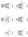
- Fig. 1 The circuit that results from carrying out the method according to the invention is shown as a diagram. It starts with casting mold parts and cores made from molding material made from new, previously unused core sand, e.g. B. quartz sand, and a conventional binder, for example a commercially available cold box binder, is mixed. In the same way, new filling material, for example ceramic granules with an average grain size of 1.5 - 25 mm, is used, which for the first use is heated to the required minimum temperature, e.g. B. 500 °C, must be heated before it can be used. Furthermore, these starting materials can be reused in the cycle, as explained below.
- a conventional binder for example a commercially available cold box binder
- Thermoreactor T shown in various phases of the method according to the invention has a sieve plate 1 on which a casting mold 2 prepared for pouring an iron casting melt is placed.
- the casting mold 2 is intended for the casting production of a casting G, which in the present example is a cylinder crankcase for a commercial vehicle internal combustion engine.
- the casting mold 2 is assembled in a conventional manner as a core package from a large number of outer cores or molded parts arranged on the outside and casting cores arranged on the inside.
- the mold 2 may include components made of steel or other indestructible materials. These include, for example, cooling molds and the like, which are arranged in the casting mold 2 in order to achieve a directed solidification of the casting G through accelerated solidification of the melt that comes into contact with the cooling mold.
- the casting mold 2 delimits a mold cavity 3 from the environment U, into which the iron casting melt is poured in order to form the casting G.
- the molten iron flows into the mold cavity 3 via a gate system, which is not shown here for the sake of clarity.
- the sieve plate 1 is supported with its edge on a circumferential edge shoulder 4 of a collecting container 5.
- a sealing element 6 is incorporated into the circumferential contact area of the edge shoulder 4.
- the housing 7 is designed in the manner of a hood and encases the mold 2 on its outer peripheral surfaces 8.
- the circumference of the space delimited by the housing 7 is oversized compared to the circumference of the casting mold 2, so that after the housing 7 has been placed on the sieve base 1 between the outer peripheral surface of the mold 2 and the inner surface 9 of the housing 7, a filling space 10 is formed.
- the housing With its edge assigned to the collecting container 5, the housing sits on the sealing element 6, so that a tight seal of the filling space 10 with respect to the environment U is guaranteed.
- the enclosure consists of a thermally insulating material, which can consist of several layers, one layer of which ensures the necessary dimensional stability of the enclosure 7 and another layer ensures the thermal insulation.
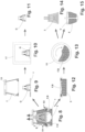
- the housing 7 delimits a large opening 11, through which the casting mold 2 can be filled with cast iron melt and the filling space 10 with filling material F ( Fig. 3 ).
- a storage container V is positioned above the opening 11, from which the hot filling material F is then fed into the filling space 10 via a distribution system 12 lets trickle down ( Fig. 4 ).
- the filling material package filled into the filling space 10 can be compacted if necessary.
- a cover 13 is then placed on the opening 11, which also has an opening 14 through which the iron casting melt can be filled into the casting mold 2 ( Fig. 5 ).
- the iron casting melt is then poured into the casting mold 2 ( Fig. 6 ).
- oxygen-containing ambient air can enter the filling space 10 via a gas inlet 15 formed in the lower edge region of the housing 7.
- ambient air which enters the collecting container 5 via an access 16, is sucked through the sieve base 1 into the filling space 10 ( Fig. 7 ).
- the solvent contained in the binder evaporates. That emerging from the mold 2 Vaporous solvent reaches a concentration in the filling space 10 at which it automatically ignites and burns off. Due to the heat released, the granular filling material F, brought to a temperature Tmin of approximately 500 °C, is heated beyond the limit temperature Tlimit of 700 °C until its temperature reaches the maximum temperature Tmax of approximately 900 °C.
- the filling material heated in this way takes on the function of a heat storage, through which the temperature of the mold 2 and in the filling space 10 is above a temperature limit of 700 ° C level is maintained. In this way, the combustion of the binder components and other potential pollutants emerging from the mold 2 continues until no more binder evaporates from the mold 2. The vaporous substances that may then still emerge from the mold 2 are oxidized or otherwise rendered harmless by the high temperature prevailing in the filling space 10.
- the filling material pack in the filling space 10 supports the casting mold 2 on its peripheral surfaces and thus prevents the iron casting melt from breaking through.
- the flow of the gases emerging from the casting mold 2 through the filling material F causes good mixing with the supplied gas flow S1, S2, a longer residence time and good reactivity.
- the casting mold 2 is heated both by the combustion of the binder system and the heat introduced by the metal poured into the casting mold 2, as well as by the preheated filling material F.
- the binder system holding the molded parts and cores of the mold 2 together is almost completely destroyed.
- the molded parts and cores then break down into fragments B or individual grains of sand.
- Temperatures of the filling material F and the gases flowing in the filling space 10 are optimally well above 700 ° C.
- the conditions in the thermal reactor T are designed in such a way that the regeneration process and the exhaust gas treatment take place independently of system availability. Determining and set variables are the starting temperature of the filler F, the oxygen-containing gas streams S1, S2 flowing in via the gas inlet 15 and the access 16 and the casting mold 2 itself.
- the progress of the destruction of the casting mold 2 and the solidification process of the iron casting melt poured into the casting mold 2 are adapted to one another in such a way that the casting G has solidified sufficiently when the casting mold 2 begins to disintegrate.
- the collecting container 5 with the molding material-filling material mixture contained in it is separated from the sieve base 1 and the housing 7 is also removed from the sieve base 1.
- the cast part G which has been largely removed from sand, is now freely accessible and can be cooled in a controlled manner in a tunnel-like space 17 provided for this purpose ( Fig. 10 ).
- the casting G has a high temperature when removed due to the process in which the austenite transformation is not yet complete and rapid cooling would lead to internal stresses and thus cracks. For this reason, the casting G is slowly cooled in a cooling tunnel 17 according to the annealing curves during stress-relieving annealing.
- the cooling air supplied is dimensioned so that the cooling profile is achieved in a product-specific manner.
- the still hot mixture of filling material F, core sand and fragments B contained in the collecting container 5 is intensively mixed in a grinder 18, which can be a rotary tube, for example, and sufficient oxidation air is added so that any remaining binder residues may still be present afterburn.
- the filling material F can also be separated from the core sand and both can be fed to separate cooling. Such regeneration ensures that the binder system is completely burned and also prepares the core sand surface through mechanical friction for good adhesion of the binder for reuse as core sand.
- the core sand obtained is cooled down to almost room temperature and, after fraction separation, is processed again into casting mold parts or casting cores for a new casting mold 2.
- the filling material F is cooled to the intended starting temperature Tmin and filled into the storage container V in the circuit for refilling the filling space 10.
- the amount of combustion air passed into the filling space 10 as gas streams S1, S2 is regulated via mechanically adjustable flaps or slides, with which the opening cross sections of the gas inlet 15 and of access 16 can be adjusted.
- the respective setting can first be determined via the stoichiometric amount of air required for combustion of the binder system and then fine-tuned via measurements of CO, NO through which the exhaust gases arising in the filling space 10 are removed from the housing 7.
- Phase 1 This phase of intensive combustion of the binder evaporating from the mold 2 lasts until the concentration Kpollutant of the combustible gases entering the filling space 10 from the mold 2, essentially formed by the evaporating binder, decreases so much that at Combustion would no longer take place at room temperature.
- the filling material F which is, for example, ceramic filling bodies
- care is taken to ensure that the individual grains of the filling material F have a high compressive strength in order to absorb the compressive forces during casting and to keep the abrasion loss as low as possible during circulation.
- Another selection criterion is a low heat capacity Combination with the bulk density of the filling material F in order to get a temperature rise above 700 °C from phase 1 as quickly as possible. Oxidation in the bulk material, with an adjusted supply of combustion air and a relatively low temperature, largely prevents the formation of nitrogen oxide.
- the excreting exhaust gases essentially heat up the filling material bed even in the first phase, a temperature profile results within the bed which ensures clean combustion.
- the combustion air follows a vertical upward direction due to the heat convection flow arising in the filling space 10 and the outgassing of pollutants from the mold 2 follows a horizontal direction into the filling material package due to the strong steam formation in the first phase.
- the crossing of the gas streams within the filling material F ensures good mixing.
- the thermal energy Qa released by the cooling of the melt and the combustion of the binder as well as that for heating the filling material as well as the heating of the core sand of the casting mold required thermal energy Qb was determined.
- K ⁇ 650 K
- Qa 1 950 J / kgK ⁇ ⁇ 650 K ⁇ 170 kg ⁇ 1 / 1000 MJ / kJ ⁇ 16.3
- Qa 1 ⁇ 121 MJ .
Claims (15)
- Procédé servant à couler des pièces en fonte (G) dans lequel de la matière fondue métallique est déversée dans un moule de coulée qui entoure une cavité (3) reproduisant la pièce en fonte à produire, le moule de coulé (2) étant constitué en tant que moule perdu à partir d'une ou plusieurs pièces ou noyaux de moule de coulée qui sont formés d'une matière de moulage constituée de sable de noyautage, d'un liant et, en option, d'un ou plusieurs additifs pour l'ajustement de certaines propriétés de la matière de moulage, comprenant les étapes de travail suivantes :- mise à disposition du moule de coulée (2) ;- l'encapsulage du moule de coulée (2) dans un boîtier (7) en formant un espace de remplissage (10) entre au moins une section de surface intérieure (9) du boîtier (7) et une section de surface extérieure (8) associée du moule de coulée (2) ;- remplissage de l'espace de remplissage (10) avec un produit de remplissage (F) fluide ;- déversement de la matière fondue métallique dans le moule de coulée (2),caractérisé en ce que- le moule de coulée (2) commençant à dégager, avec le déversement de la matière fondue métallique, de la chaleur suite à l'apport de chaleur par la matière fondue métallique chaude, et- dans lequel, suite à l'apport de chaleur par la matière fondue métallique, le liant de la matière de moulage commencent à s'évaporer et à se consumer en perdant ainsi son action, et le moule de coulée (2) se désintègre en fragments (B),
le produit de remplissage (F) déversé dans l'espace de remplissage (10) possède une masse volumique apparente si faible, qu'après le remplissage de l'espace de remplissage (10), l'emballage de produit de remplissage, formé à partir du produit de remplissage (F), peut être traversé par un flux de gaz (S1, S2), et en ce que le produit de remplissage (F) présente, lors du remplissage de l'espace de remplissage (10), une température minimale (Tmin), à partir de laquelle la température du produit de remplissage (F) augmente jusqu'au-delà d'une valeur supérieure à une température limite (TGrenz) par une chaleur de processus qui est formée par la chaleur dégagée par le moule de coulée (2) et par la chaleur libérée lors de la combustion du liant, le liant s'évaporant du moule de coulée (2) et entrant en contact avec le produit de remplissage (F) s'enflammant et se consumant à ladite température limite. - Procédé selon la revendication 1, caractérisé en ce que le produit P issu de la masse volumique apparente Sd et de la capacité thermique spécifique cp est au maximum de 1 kJ/dm3K.
- Procédé selon l'une des revendications précédentes, caractérisé en ce que la masse volumique apparente Sd est au maximum de 4 kg/dm3.
- Procédé selon l'une des revendications précédentes, caractérisé en ce que le produit de remplissage (F) possède une capacité thermique spécifique cp au maximum de 1 kJ/kgK.
- Procédé selon l'une des revendications précédentes, caractérisé en ce que le produit de remplissage (F) est constitué de granulés d'un diamètre moyen de 1,5 à 100 mm.
- Procédé selon l'une des revendications précédentes, caractérisé en ce que la température du produit de remplissage (F), lors du remplissage de l'espace de remplissage (10), est d'au moins 500 °C.
- Procédé selon l'une des revendications précédentes, caractérisé en ce que la température limite (TGrenz) est de 700 °C.
- Procédé selon l'une des revendications précédentes, caractérisé en ce que l'encapsulation présente une entrée de gaz (15) et une sortie de gaz d'échappement (19) et en ce que le produit de remplissage (F) contenu dans l'espace de remplissage (10) est traversé, au moins temporairement et partiellement, par un flux de gaz contenant de l'oxygène (S1, S2).
- Procédé selon la revendication 7, caractérisé en ce que le flux de gaz (S1, S2) est chauffé à une température supérieure à la température ambiante.
- Procédé selon l'une des revendications 7 à 9, caractérisé en ce que le flux de gaz (S1, S2) est régulé en fonction du débit volumique de gaz d'échappement sortant de la sortie de gaz d'échappement (19).
- Procédé selon l'une des revendications 7 à 10, caractérisé en ce qu'une mesure des gaz d'échappement est effectuée à la sortie des gaz d'échappement (19) et en ce que le flux de gaz (S1, S2) est régulé en fonction du résultat de cette mesure.
- Procédé selon l'une des revendications 7 à 11, caractérisé en ce qu'un flux partiel des gaz de combustion sortant de la sortie des gaz d'échappement (19) est mélangé au flux de gaz contenant de l'oxygène (S1, S2) et le mélange obtenu est acheminé dans le boîtier (7).
- Procédé selon l'une des revendications précédentes, caractérisé en ce que le boîtier (7) est équipé d'un dispositif catalyseur pour la décomposition de polluants contenus dans les produits de combustion du liant.
- Procédé selon l'une des revendications précédentes, caractérisé en ce que le moule de coulée (2) est placé sur un fond de tamisage (1) et en ce que les fragments (B) du moule de coulée (2) et le produit de remplissage (F), s'écoulant conjointement à travers le fond de tamisage (1), sont recueillis, préparés et, après la préparation, séparés l'un de l'autre.
- Procédé selon l'une des revendications précédentes, caractérisé en ce que la pièce en fonte (G) subit, après la désintégration du moule de coulée (2), un traitement thermique au cours duquel elle est refroidie de manière contrôlée selon une courbe de refroidissement déterminée.
Applications Claiming Priority (3)
| Application Number | Priority Date | Filing Date | Title |
|---|---|---|---|
| DE102014110826.4A DE102014110826A1 (de) | 2014-07-30 | 2014-07-30 | Verfahren zum Gießen von Gussteilen |
| PCT/EP2015/066546 WO2016016035A1 (fr) | 2014-07-30 | 2015-07-20 | Procédé servant à couler des pièces en fonte |
| EP15738697.0A EP3119545B1 (fr) | 2014-07-30 | 2015-07-20 | Procédé servant à couler des pièces en fonte |
Related Parent Applications (1)
| Application Number | Title | Priority Date | Filing Date |
|---|---|---|---|
| EP15738697.0A Division EP3119545B1 (fr) | 2014-07-30 | 2015-07-20 | Procédé servant à couler des pièces en fonte |
Publications (3)
| Publication Number | Publication Date |
|---|---|
| EP3597329A1 EP3597329A1 (fr) | 2020-01-22 |
| EP3597329C0 EP3597329C0 (fr) | 2024-01-03 |
| EP3597329B1 true EP3597329B1 (fr) | 2024-01-03 |
Family
ID=53673104
Family Applications (2)
| Application Number | Title | Priority Date | Filing Date |
|---|---|---|---|
| EP19193631.9A Active EP3597329B1 (fr) | 2014-07-30 | 2015-07-20 | Procédé de coulée de pièces coulées |
| EP15738697.0A Active EP3119545B1 (fr) | 2014-07-30 | 2015-07-20 | Procédé servant à couler des pièces en fonte |
Family Applications After (1)
| Application Number | Title | Priority Date | Filing Date |
|---|---|---|---|
| EP15738697.0A Active EP3119545B1 (fr) | 2014-07-30 | 2015-07-20 | Procédé servant à couler des pièces en fonte |
Country Status (20)
| Country | Link |
|---|---|
| US (1) | US9890439B2 (fr) |
| EP (2) | EP3597329B1 (fr) |
| JP (1) | JP6275324B2 (fr) |
| KR (1) | KR101845505B1 (fr) |
| CN (1) | CN106536083B (fr) |
| BR (1) | BR112016023696B8 (fr) |
| CA (1) | CA2948750C (fr) |
| DE (1) | DE102014110826A1 (fr) |
| DK (1) | DK3119545T3 (fr) |
| ES (1) | ES2759264T3 (fr) |
| HR (1) | HRP20192115T1 (fr) |
| HU (1) | HUE046428T2 (fr) |
| MX (1) | MX361595B (fr) |
| PL (1) | PL3119545T3 (fr) |
| PT (1) | PT3119545T (fr) |
| RS (1) | RS59702B1 (fr) |
| RU (1) | RU2645824C1 (fr) |
| SI (1) | SI3119545T1 (fr) |
| WO (1) | WO2016016035A1 (fr) |
| ZA (1) | ZA201606111B (fr) |
Families Citing this family (8)
| Publication number | Priority date | Publication date | Assignee | Title |
|---|---|---|---|---|
| CN106077474A (zh) * | 2016-07-26 | 2016-11-09 | 柳州金特新型耐磨材料股份有限公司 | 一种后桥壳体热处理工艺 |
| US10378661B2 (en) * | 2016-11-08 | 2019-08-13 | Mueller International, Llc | Valve body with integral bypass |
| US10661332B2 (en) | 2017-04-10 | 2020-05-26 | Mueller International, Llc | Monolithic bypass |
| KR20200067485A (ko) * | 2018-12-04 | 2020-06-12 | 현대자동차주식회사 | 유로부가 형성된 주조품 제조 방법 및 그 방법에 의해 제조되는 주조품 |
| KR20200095200A (ko) * | 2019-01-31 | 2020-08-10 | 현대자동차주식회사 | 유로부가 형성된 주조품 제조 방법 및 그 방법에 의해 제조되는 주조품 |
| CN110153445A (zh) * | 2019-05-31 | 2019-08-23 | 东莞市乔锋机械有限公司 | 一种高比强度比刚度材料增强的夹芯结构 |
| DE102021115727A1 (de) | 2021-06-17 | 2022-12-22 | Fritz Winter Eisengiesserei Gmbh & Co. Kg | Verfahren zum Gießen von Gussteilen |
| CN116174660B (zh) * | 2023-04-25 | 2023-06-30 | 蓬莱三和铸造有限公司 | 一种用于矿车平衡轴的高精度铸造装置 |
Family Cites Families (28)
| Publication number | Priority date | Publication date | Assignee | Title |
|---|---|---|---|---|
| DE1187768B (de) * | 1959-04-13 | 1965-02-25 | Howe Sound Co | Verfahren zum Herstellen von Giessereiformmasken |
| DE2044171C2 (de) | 1970-09-05 | 1972-05-31 | Lottermoser, Manfred, Dipl.-Phys., 3201 Barienrode | Verfahren zum härten von giessereifomteilen |
| DE2146031A1 (de) * | 1971-09-15 | 1973-03-22 | Eduard Dipl Ing Baur | Giessform und schalenfoermige trichter fuer giessformen |
| DE3107180C2 (de) * | 1981-02-26 | 1984-02-02 | C.T.Z. Plan GmbH Industrieplanung und -beratung, 6361 Niddatal | Verfahren zur Herstellung von durch Kühlung gebundenen Schalenformen und Kernen für das Gießen von Metallen |
| CH652428A5 (de) * | 1981-03-24 | 1985-11-15 | Canron Inc Crissier | Auf dem gleis fahrbare schotterplaniermaschine. |
| JPS5829566A (ja) * | 1981-07-22 | 1983-02-21 | Toyota Motor Corp | フルモ−ルド鋳造法 |
| DE3323697C1 (de) * | 1983-07-01 | 1985-02-28 | Gerhard 5905 Freudenberg Müller-Späth | Verfahren zum Herstellen eines Giessstueckes in einer Giessform |
| US5086019A (en) * | 1986-09-16 | 1992-02-04 | Lanxide Technology Company, Lp | Reservoir feed method of making ceramic composite structures and structures made thereby |
| JPH0635047B2 (ja) * | 1987-11-06 | 1994-05-11 | トヨタ自動車株式会社 | 中子の除去方法 |
| JPH03465A (ja) * | 1989-05-26 | 1991-01-07 | Toyota Motor Corp | 中子除去方法 |
| EP0546210B2 (fr) | 1991-05-24 | 2003-07-09 | Consolidated Engineering Company, Inc. | Procédé et dispositif pour le traitement thermique de pièces coulées |
| KR100263975B1 (ko) | 1992-08-13 | 2000-09-01 | 스콧 피. 크래프턴 | 금속 주물의 열처리 및 노 내부 주물사 재생 방법 및 장치 |
| JPH1122658A (ja) | 1997-07-04 | 1999-01-26 | Sanden Corp | スクロール型圧縮機 |
| DE19813847A1 (de) * | 1998-03-27 | 1999-09-30 | Wagner Heinrich Sinto Masch | Gießform und Verfahren zu deren Herstellung |
| MXPA02000936A (es) * | 1999-07-29 | 2002-08-06 | Cons Eng Co Inc | Tratamiento termico y remocion de arena para piezas fundidas. |
| US6910522B2 (en) | 1999-07-29 | 2005-06-28 | Consolidated Engineering Company, Inc. | Methods and apparatus for heat treatment and sand removal for castings |
| US6776219B1 (en) * | 1999-09-20 | 2004-08-17 | Metal Matrix Cast Composites, Inc. | Castable refractory investment mold materials and methods of their use in infiltration casting |
| MXPA04002424A (es) * | 2001-09-14 | 2005-04-11 | Hydro Aluminium Deutschland | Metodo para la fabricacion de piezas fundidas, arena de moldeo y su uso para la implementacion del metodo. |
| DE10209183A1 (de) * | 2002-03-04 | 2003-10-02 | Vaw Mandl & Berger Gmbh Linz | Formstoff für die Herstellung von Gießformteilen |
| US6766850B2 (en) * | 2001-12-27 | 2004-07-27 | Caterpillar Inc | Pressure casting using a supported shell mold |
| US6662854B2 (en) * | 2002-04-05 | 2003-12-16 | Ashland Inc. | Cold-box foundry binder systems having improved shakeout |
| WO2005044485A2 (fr) * | 2003-10-28 | 2005-05-19 | Hos Hottinger Systems Gbr | Procede de coulee de pieces moulees |
| BRPI0509560A (pt) * | 2004-04-01 | 2007-09-18 | Sintokogio Ltd | método de vazamento, dispositivo e produto fundido em um processo de moldagem a vácuo |
| DE102005046027A1 (de) * | 2005-09-05 | 2007-03-08 | HOS Hottinger Systems GbR (vertretungsberechtigter Gesellschafter: Walter Leo Pöhlandt, 68782 Brühl) | Verfahren zum Gießen von Formteilen |
| JP5015841B2 (ja) * | 2008-03-31 | 2012-08-29 | トヨタ自動車株式会社 | 成形型予熱装置及び成形型予熱方法 |
| US8656983B2 (en) * | 2010-11-22 | 2014-02-25 | Halliburton Energy Services, Inc. | Use of liquid metal filters in forming matrix drill bits |
| JP5829566B2 (ja) | 2012-03-30 | 2015-12-09 | 株式会社吉野工業所 | ブロー成形装置 |
| DE102012103884A1 (de) * | 2012-05-03 | 2013-11-07 | Fritz Winter Eisengiesserei Gmbh & Co. Kg | Verfahren zum Gießen eines mit mindestens einer Durchgangsöffnung versehenen Gussteils |
-
2014
- 2014-07-30 DE DE102014110826.4A patent/DE102014110826A1/de active Pending
-
2015
- 2015-07-20 CA CA2948750A patent/CA2948750C/fr active Active
- 2015-07-20 CN CN201580040068.5A patent/CN106536083B/zh active Active
- 2015-07-20 RU RU2016141603A patent/RU2645824C1/ru active
- 2015-07-20 ES ES15738697T patent/ES2759264T3/es active Active
- 2015-07-20 MX MX2016012496A patent/MX361595B/es active IP Right Grant
- 2015-07-20 BR BR112016023696A patent/BR112016023696B8/pt active IP Right Grant
- 2015-07-20 RS RS20191524A patent/RS59702B1/sr unknown
- 2015-07-20 PL PL15738697T patent/PL3119545T3/pl unknown
- 2015-07-20 EP EP19193631.9A patent/EP3597329B1/fr active Active
- 2015-07-20 WO PCT/EP2015/066546 patent/WO2016016035A1/fr active Application Filing
- 2015-07-20 JP JP2017505184A patent/JP6275324B2/ja active Active
- 2015-07-20 DK DK15738697T patent/DK3119545T3/da active
- 2015-07-20 SI SI201531007T patent/SI3119545T1/sl unknown
- 2015-07-20 US US15/315,079 patent/US9890439B2/en active Active
- 2015-07-20 PT PT157386970T patent/PT3119545T/pt unknown
- 2015-07-20 KR KR1020177002882A patent/KR101845505B1/ko active IP Right Grant
- 2015-07-20 EP EP15738697.0A patent/EP3119545B1/fr active Active
- 2015-07-20 HU HUE15738697A patent/HUE046428T2/hu unknown
-
2016
- 2016-09-02 ZA ZA2016/06111A patent/ZA201606111B/en unknown
-
2019
- 2019-11-26 HR HRP20192115TT patent/HRP20192115T1/hr unknown
Also Published As
| Publication number | Publication date |
|---|---|
| BR112016023696B8 (pt) | 2021-11-16 |
| US9890439B2 (en) | 2018-02-13 |
| SI3119545T1 (sl) | 2020-01-31 |
| DK3119545T3 (da) | 2019-12-02 |
| PL3119545T3 (pl) | 2020-03-31 |
| MX2016012496A (es) | 2017-01-09 |
| KR101845505B1 (ko) | 2018-05-18 |
| CN106536083A (zh) | 2017-03-22 |
| BR112016023696B1 (pt) | 2021-08-31 |
| CA2948750C (fr) | 2018-01-02 |
| HRP20192115T1 (hr) | 2020-02-21 |
| PT3119545T (pt) | 2019-12-09 |
| BR112016023696A2 (fr) | 2017-08-22 |
| EP3119545A1 (fr) | 2017-01-25 |
| MX361595B (es) | 2018-12-10 |
| CN106536083B (zh) | 2018-09-28 |
| JP2017525570A (ja) | 2017-09-07 |
| EP3597329C0 (fr) | 2024-01-03 |
| US20170198366A1 (en) | 2017-07-13 |
| KR20170028392A (ko) | 2017-03-13 |
| DE102014110826A1 (de) | 2016-02-04 |
| HUE046428T2 (hu) | 2020-03-30 |
| EP3119545B1 (fr) | 2019-08-28 |
| ZA201606111B (en) | 2017-09-27 |
| EP3597329A1 (fr) | 2020-01-22 |
| RS59702B1 (sr) | 2020-01-31 |
| CA2948750A1 (fr) | 2016-02-04 |
| JP6275324B2 (ja) | 2018-02-07 |
| ES2759264T3 (es) | 2020-05-08 |
| RU2645824C1 (ru) | 2018-02-28 |
| WO2016016035A1 (fr) | 2016-02-04 |
Similar Documents
| Publication | Publication Date | Title |
|---|---|---|
| EP3597329B1 (fr) | Procédé de coulée de pièces coulées | |
| EP0890400B1 (fr) | Procédé de moulage pour la fabrication des objets moulés métalliques | |
| EP4355512A1 (fr) | Procédé de coulée de pièces moulées | |
| EP3450050A1 (fr) | Dispositif de coulée basse pression | |
| EP3041623B1 (fr) | Procédé permettant de démouler d'un moule une pièce moulée à partir d'un métal léger fondu | |
| WO2007028362A1 (fr) | Procede pour couler des pieces | |
| DE1758544A1 (de) | Verfahren zur Herstellung von gesonderten Stuecken aus Ferrolegierungen | |
| DE102016112039B4 (de) | Wärmedämmende Platte, insbesondere Abdeckplatte für Metallschmelzen, sowie Verfahren zur Herstellung der Platte und deren Verwendung | |
| DE102016112044B4 (de) | Verwendung einer wärmedämmenden Platte zur Isolation von Metallschmelzen gegenüber der Atmosphäre oder einem metallurgischen Gefäß | |
| AT517866B1 (de) | Vorrichtung und Verfahren zum Schutz der Innenwand von Schlackentiegeln | |
| DE19651721A1 (de) | Verfahren zur Herstellung eines Formkörpers | |
| DE4427586C1 (de) | Vorrichtung zum Aufbereiten von Gießereialtsand | |
| DE102004013973B4 (de) | Verfahren zum Gießen von Formteilen | |
| DE2064205C2 (de) | Verfahren zur Herstellung von feuerbeständigen Auskleidungen oder Formkörpern | |
| WO2005044485A2 (fr) | Procede de coulee de pieces moulees | |
| DE11055C (de) | Verfahren, um gröfsere Glaskörper von unregelmäfsigen Formen in möglichst grofser Haltbarkeit herzustellen und zu kühlen | |
| DE1145310B (de) | Verfahren zum Herstellen von Formen oder Kernen fuer Giessereizwecke | |
| DE1671040C (de) | Verfahren zur Herstellung von feuerfesten Steinen | |
| DE2123632B1 (de) | Leicht enfernbare formteile, insbesondere kerne für giessereizwecke und verfahren zu deren herstellung | |
| DE3836632A1 (de) | Feuerfestes auskleidungsmaterial auf erdalkalisilicatbasis und verfahren zu seiner herstellung | |
| DE10361535A1 (de) | Verfahren zum Gießen von Formteilen | |
| CH556701A (de) | Verfahren zur herstellung einer giessform. |
Legal Events
| Date | Code | Title | Description |
|---|---|---|---|
| PUAI | Public reference made under article 153(3) epc to a published international application that has entered the european phase |
Free format text: ORIGINAL CODE: 0009012 |
|
| STAA | Information on the status of an ep patent application or granted ep patent |
Free format text: STATUS: THE APPLICATION HAS BEEN PUBLISHED |
|
| AC | Divisional application: reference to earlier application |
Ref document number: 3119545 Country of ref document: EP Kind code of ref document: P |
|
| AK | Designated contracting states |
Kind code of ref document: A1 Designated state(s): AL AT BE BG CH CY CZ DE DK EE ES FI FR GB GR HR HU IE IS IT LI LT LU LV MC MK MT NL NO PL PT RO RS SE SI SK SM TR |
|
| STAA | Information on the status of an ep patent application or granted ep patent |
Free format text: STATUS: REQUEST FOR EXAMINATION WAS MADE |
|
| 17P | Request for examination filed |
Effective date: 20200722 |
|
| RBV | Designated contracting states (corrected) |
Designated state(s): AL AT BE BG CH CY CZ DE DK EE ES FI FR GB GR HR HU IE IS IT LI LT LU LV MC MK MT NL NO PL PT RO RS SE SI SK SM TR |
|
| GRAP | Despatch of communication of intention to grant a patent |
Free format text: ORIGINAL CODE: EPIDOSNIGR1 |
|
| STAA | Information on the status of an ep patent application or granted ep patent |
Free format text: STATUS: GRANT OF PATENT IS INTENDED |
|
| RIC1 | Information provided on ipc code assigned before grant |
Ipc: B22D 45/00 20060101ALI20230208BHEP Ipc: B22D 30/00 20060101ALI20230208BHEP Ipc: B22C 9/04 20060101ALI20230208BHEP Ipc: C21D 9/00 20060101ALI20230208BHEP Ipc: B22C 9/10 20060101ALI20230208BHEP Ipc: B22C 9/02 20060101ALI20230208BHEP Ipc: B22D 29/00 20060101AFI20230208BHEP |
|
| INTG | Intention to grant announced |
Effective date: 20230224 |
|
| P01 | Opt-out of the competence of the unified patent court (upc) registered |
Effective date: 20230517 |
|
| GRAJ | Information related to disapproval of communication of intention to grant by the applicant or resumption of examination proceedings by the epo deleted |
Free format text: ORIGINAL CODE: EPIDOSDIGR1 |
|
| STAA | Information on the status of an ep patent application or granted ep patent |
Free format text: STATUS: REQUEST FOR EXAMINATION WAS MADE |
|
| GRAP | Despatch of communication of intention to grant a patent |
Free format text: ORIGINAL CODE: EPIDOSNIGR1 |
|
| STAA | Information on the status of an ep patent application or granted ep patent |
Free format text: STATUS: GRANT OF PATENT IS INTENDED |
|
| INTC | Intention to grant announced (deleted) | ||
| INTG | Intention to grant announced |
Effective date: 20230714 |
|
| GRAS | Grant fee paid |
Free format text: ORIGINAL CODE: EPIDOSNIGR3 |
|
| GRAA | (expected) grant |
Free format text: ORIGINAL CODE: 0009210 |
|
| STAA | Information on the status of an ep patent application or granted ep patent |
Free format text: STATUS: THE PATENT HAS BEEN GRANTED |
|
| AC | Divisional application: reference to earlier application |
Ref document number: 3119545 Country of ref document: EP Kind code of ref document: P |
|
| AK | Designated contracting states |
Kind code of ref document: B1 Designated state(s): AL AT BE BG CH CY CZ DE DK EE ES FI FR GB GR HR HU IE IS IT LI LT LU LV MC MK MT NL NO PL PT RO RS SE SI SK SM TR |
|
| REG | Reference to a national code |
Ref country code: GB Ref legal event code: FG4D Free format text: NOT ENGLISH |
|
| REG | Reference to a national code |
Ref country code: CH Ref legal event code: EP |
|
| REG | Reference to a national code |
Ref country code: DE Ref legal event code: R096 Ref document number: 502015016725 Country of ref document: DE |
|
| REG | Reference to a national code |
Ref country code: IE Ref legal event code: FG4D Free format text: LANGUAGE OF EP DOCUMENT: GERMAN |
|
| U01 | Request for unitary effect filed |
Effective date: 20240205 |
|
| U07 | Unitary effect registered |
Designated state(s): AT BE BG DE DK EE FI FR IT LT LU LV MT NL PT SE SI Effective date: 20240213 |
|
| P04 | Withdrawal of opt-out of the competence of the unified patent court (upc) registered |
Effective date: 20240209 |