EP3597006B1 - Energiesteuerelemente für verbesserte mikrowellenheizung von verpackten artikeln - Google Patents
Energiesteuerelemente für verbesserte mikrowellenheizung von verpackten artikeln Download PDFInfo
- Publication number
- EP3597006B1 EP3597006B1 EP18767080.7A EP18767080A EP3597006B1 EP 3597006 B1 EP3597006 B1 EP 3597006B1 EP 18767080 A EP18767080 A EP 18767080A EP 3597006 B1 EP3597006 B1 EP 3597006B1
- Authority
- EP
- European Patent Office
- Prior art keywords
- microwave
- heating
- articles
- energy
- foodstuff
- Prior art date
- Legal status (The legal status is an assumption and is not a legal conclusion. Google has not performed a legal analysis and makes no representation as to the accuracy of the status listed.)
- Active
Links
Images


Classifications
-
- B—PERFORMING OPERATIONS; TRANSPORTING
- B65—CONVEYING; PACKING; STORING; HANDLING THIN OR FILAMENTARY MATERIAL
- B65D—CONTAINERS FOR STORAGE OR TRANSPORT OF ARTICLES OR MATERIALS, e.g. BAGS, BARRELS, BOTTLES, BOXES, CANS, CARTONS, CRATES, DRUMS, JARS, TANKS, HOPPERS, FORWARDING CONTAINERS; ACCESSORIES, CLOSURES, OR FITTINGS THEREFOR; PACKAGING ELEMENTS; PACKAGES
- B65D81/00—Containers, packaging elements, or packages, for contents presenting particular transport or storage problems, or adapted to be used for non-packaging purposes after removal of contents
- B65D81/34—Containers, packaging elements, or packages, for contents presenting particular transport or storage problems, or adapted to be used for non-packaging purposes after removal of contents for packaging foodstuffs or other articles intended to be cooked or heated within the package
- B65D81/3446—Containers, packaging elements, or packages, for contents presenting particular transport or storage problems, or adapted to be used for non-packaging purposes after removal of contents for packaging foodstuffs or other articles intended to be cooked or heated within the package specially adapted to be heated by microwaves
- B65D81/3453—Rigid containers, e.g. trays, bottles, boxes, cups
-
- B—PERFORMING OPERATIONS; TRANSPORTING
- B65—CONVEYING; PACKING; STORING; HANDLING THIN OR FILAMENTARY MATERIAL
- B65D—CONTAINERS FOR STORAGE OR TRANSPORT OF ARTICLES OR MATERIALS, e.g. BAGS, BARRELS, BOTTLES, BOXES, CANS, CARTONS, CRATES, DRUMS, JARS, TANKS, HOPPERS, FORWARDING CONTAINERS; ACCESSORIES, CLOSURES, OR FITTINGS THEREFOR; PACKAGING ELEMENTS; PACKAGES
- B65D81/00—Containers, packaging elements, or packages, for contents presenting particular transport or storage problems, or adapted to be used for non-packaging purposes after removal of contents
- B65D81/34—Containers, packaging elements, or packages, for contents presenting particular transport or storage problems, or adapted to be used for non-packaging purposes after removal of contents for packaging foodstuffs or other articles intended to be cooked or heated within the package
- B65D81/3446—Containers, packaging elements, or packages, for contents presenting particular transport or storage problems, or adapted to be used for non-packaging purposes after removal of contents for packaging foodstuffs or other articles intended to be cooked or heated within the package specially adapted to be heated by microwaves
- B65D81/3461—Flexible containers, e.g. bags, pouches, envelopes
-
- H—ELECTRICITY
- H05—ELECTRIC TECHNIQUES NOT OTHERWISE PROVIDED FOR
- H05B—ELECTRIC HEATING; ELECTRIC LIGHT SOURCES NOT OTHERWISE PROVIDED FOR; CIRCUIT ARRANGEMENTS FOR ELECTRIC LIGHT SOURCES, IN GENERAL
- H05B6/00—Heating by electric, magnetic or electromagnetic fields
- H05B6/64—Heating using microwaves
- H05B6/6408—Supports or covers specially adapted for use in microwave heating apparatus
-
- H—ELECTRICITY
- H05—ELECTRIC TECHNIQUES NOT OTHERWISE PROVIDED FOR
- H05B—ELECTRIC HEATING; ELECTRIC LIGHT SOURCES NOT OTHERWISE PROVIDED FOR; CIRCUIT ARRANGEMENTS FOR ELECTRIC LIGHT SOURCES, IN GENERAL
- H05B6/00—Heating by electric, magnetic or electromagnetic fields
- H05B6/64—Heating using microwaves
- H05B6/647—Aspects related to microwave heating combined with other heating techniques
- H05B6/6491—Aspects related to microwave heating combined with other heating techniques combined with the use of susceptors
- H05B6/6494—Aspects related to microwave heating combined with other heating techniques combined with the use of susceptors for cooking
-
- H—ELECTRICITY
- H05—ELECTRIC TECHNIQUES NOT OTHERWISE PROVIDED FOR
- H05B—ELECTRIC HEATING; ELECTRIC LIGHT SOURCES NOT OTHERWISE PROVIDED FOR; CIRCUIT ARRANGEMENTS FOR ELECTRIC LIGHT SOURCES, IN GENERAL
- H05B6/00—Heating by electric, magnetic or electromagnetic fields
- H05B6/64—Heating using microwaves
- H05B6/66—Circuits
- H05B6/68—Circuits for monitoring or control
- H05B6/687—Circuits for monitoring or control for cooking
-
- H—ELECTRICITY
- H05—ELECTRIC TECHNIQUES NOT OTHERWISE PROVIDED FOR
- H05B—ELECTRIC HEATING; ELECTRIC LIGHT SOURCES NOT OTHERWISE PROVIDED FOR; CIRCUIT ARRANGEMENTS FOR ELECTRIC LIGHT SOURCES, IN GENERAL
- H05B6/00—Heating by electric, magnetic or electromagnetic fields
- H05B6/64—Heating using microwaves
- H05B6/70—Feed lines
- H05B6/704—Feed lines using microwave polarisers
-
- H—ELECTRICITY
- H05—ELECTRIC TECHNIQUES NOT OTHERWISE PROVIDED FOR
- H05B—ELECTRIC HEATING; ELECTRIC LIGHT SOURCES NOT OTHERWISE PROVIDED FOR; CIRCUIT ARRANGEMENTS FOR ELECTRIC LIGHT SOURCES, IN GENERAL
- H05B6/00—Heating by electric, magnetic or electromagnetic fields
- H05B6/64—Heating using microwaves
- H05B6/78—Arrangements for continuous movement of material
- H05B6/782—Arrangements for continuous movement of material wherein the material moved is food
-
- H—ELECTRICITY
- H05—ELECTRIC TECHNIQUES NOT OTHERWISE PROVIDED FOR
- H05B—ELECTRIC HEATING; ELECTRIC LIGHT SOURCES NOT OTHERWISE PROVIDED FOR; CIRCUIT ARRANGEMENTS FOR ELECTRIC LIGHT SOURCES, IN GENERAL
- H05B6/00—Heating by electric, magnetic or electromagnetic fields
- H05B6/64—Heating using microwaves
- H05B6/80—Apparatus for specific applications
- H05B6/802—Apparatus for specific applications for heating fluids
-
- B—PERFORMING OPERATIONS; TRANSPORTING
- B65—CONVEYING; PACKING; STORING; HANDLING THIN OR FILAMENTARY MATERIAL
- B65D—CONTAINERS FOR STORAGE OR TRANSPORT OF ARTICLES OR MATERIALS, e.g. BAGS, BARRELS, BOTTLES, BOXES, CANS, CARTONS, CRATES, DRUMS, JARS, TANKS, HOPPERS, FORWARDING CONTAINERS; ACCESSORIES, CLOSURES, OR FITTINGS THEREFOR; PACKAGING ELEMENTS; PACKAGES
- B65D2581/00—Containers, packaging elements, or packages, for contents presenting particular transport or storage problems, or adapted to be used for non-packaging purposes after removal of contents
- B65D2581/34—Containers, packaging elements, or packages, for contents presenting particular transport or storage problems, or adapted to be used for non-packaging purposes after removal of contents for packaging foodstuffs or other articles intended to be cooked or heated within
- B65D2581/3437—Containers, packaging elements, or packages, for contents presenting particular transport or storage problems, or adapted to be used for non-packaging purposes after removal of contents for packaging foodstuffs or other articles intended to be cooked or heated within specially adapted to be heated by microwaves
- B65D2581/3439—Means for affecting the heating or cooking properties
- B65D2581/344—Geometry or shape factors influencing the microwave heating properties
-
- B—PERFORMING OPERATIONS; TRANSPORTING
- B65—CONVEYING; PACKING; STORING; HANDLING THIN OR FILAMENTARY MATERIAL
- B65D—CONTAINERS FOR STORAGE OR TRANSPORT OF ARTICLES OR MATERIALS, e.g. BAGS, BARRELS, BOTTLES, BOXES, CANS, CARTONS, CRATES, DRUMS, JARS, TANKS, HOPPERS, FORWARDING CONTAINERS; ACCESSORIES, CLOSURES, OR FITTINGS THEREFOR; PACKAGING ELEMENTS; PACKAGES
- B65D2581/00—Containers, packaging elements, or packages, for contents presenting particular transport or storage problems, or adapted to be used for non-packaging purposes after removal of contents
- B65D2581/34—Containers, packaging elements, or packages, for contents presenting particular transport or storage problems, or adapted to be used for non-packaging purposes after removal of contents for packaging foodstuffs or other articles intended to be cooked or heated within
- B65D2581/3437—Containers, packaging elements, or packages, for contents presenting particular transport or storage problems, or adapted to be used for non-packaging purposes after removal of contents for packaging foodstuffs or other articles intended to be cooked or heated within specially adapted to be heated by microwaves
- B65D2581/3486—Dielectric characteristics of microwave reactive packaging
- B65D2581/3489—Microwave reflector, i.e. microwave shield
- B65D2581/3491—Microwave reflector, i.e. microwave shield attached to the side walls
-
- B—PERFORMING OPERATIONS; TRANSPORTING
- B65—CONVEYING; PACKING; STORING; HANDLING THIN OR FILAMENTARY MATERIAL
- B65D—CONTAINERS FOR STORAGE OR TRANSPORT OF ARTICLES OR MATERIALS, e.g. BAGS, BARRELS, BOTTLES, BOXES, CANS, CARTONS, CRATES, DRUMS, JARS, TANKS, HOPPERS, FORWARDING CONTAINERS; ACCESSORIES, CLOSURES, OR FITTINGS THEREFOR; PACKAGING ELEMENTS; PACKAGES
- B65D2581/00—Containers, packaging elements, or packages, for contents presenting particular transport or storage problems, or adapted to be used for non-packaging purposes after removal of contents
- B65D2581/34—Containers, packaging elements, or packages, for contents presenting particular transport or storage problems, or adapted to be used for non-packaging purposes after removal of contents for packaging foodstuffs or other articles intended to be cooked or heated within
- B65D2581/3437—Containers, packaging elements, or packages, for contents presenting particular transport or storage problems, or adapted to be used for non-packaging purposes after removal of contents for packaging foodstuffs or other articles intended to be cooked or heated within specially adapted to be heated by microwaves
- B65D2581/3486—Dielectric characteristics of microwave reactive packaging
- B65D2581/3489—Microwave reflector, i.e. microwave shield
- B65D2581/3493—Microwave reflector, i.e. microwave shield attached to the base surface
-
- B—PERFORMING OPERATIONS; TRANSPORTING
- B65—CONVEYING; PACKING; STORING; HANDLING THIN OR FILAMENTARY MATERIAL
- B65D—CONTAINERS FOR STORAGE OR TRANSPORT OF ARTICLES OR MATERIALS, e.g. BAGS, BARRELS, BOTTLES, BOXES, CANS, CARTONS, CRATES, DRUMS, JARS, TANKS, HOPPERS, FORWARDING CONTAINERS; ACCESSORIES, CLOSURES, OR FITTINGS THEREFOR; PACKAGING ELEMENTS; PACKAGES
- B65D2581/00—Containers, packaging elements, or packages, for contents presenting particular transport or storage problems, or adapted to be used for non-packaging purposes after removal of contents
- B65D2581/34—Containers, packaging elements, or packages, for contents presenting particular transport or storage problems, or adapted to be used for non-packaging purposes after removal of contents for packaging foodstuffs or other articles intended to be cooked or heated within
- B65D2581/3437—Containers, packaging elements, or packages, for contents presenting particular transport or storage problems, or adapted to be used for non-packaging purposes after removal of contents for packaging foodstuffs or other articles intended to be cooked or heated within specially adapted to be heated by microwaves
- B65D2581/3486—Dielectric characteristics of microwave reactive packaging
- B65D2581/3494—Microwave susceptor
- B65D2581/3497—Microwave susceptor attached to the side walls
-
- B—PERFORMING OPERATIONS; TRANSPORTING
- B65—CONVEYING; PACKING; STORING; HANDLING THIN OR FILAMENTARY MATERIAL
- B65D—CONTAINERS FOR STORAGE OR TRANSPORT OF ARTICLES OR MATERIALS, e.g. BAGS, BARRELS, BOTTLES, BOXES, CANS, CARTONS, CRATES, DRUMS, JARS, TANKS, HOPPERS, FORWARDING CONTAINERS; ACCESSORIES, CLOSURES, OR FITTINGS THEREFOR; PACKAGING ELEMENTS; PACKAGES
- B65D2581/00—Containers, packaging elements, or packages, for contents presenting particular transport or storage problems, or adapted to be used for non-packaging purposes after removal of contents
- B65D2581/34—Containers, packaging elements, or packages, for contents presenting particular transport or storage problems, or adapted to be used for non-packaging purposes after removal of contents for packaging foodstuffs or other articles intended to be cooked or heated within
- B65D2581/3437—Containers, packaging elements, or packages, for contents presenting particular transport or storage problems, or adapted to be used for non-packaging purposes after removal of contents for packaging foodstuffs or other articles intended to be cooked or heated within specially adapted to be heated by microwaves
- B65D2581/3486—Dielectric characteristics of microwave reactive packaging
- B65D2581/3494—Microwave susceptor
- B65D2581/3498—Microwave susceptor attached to the base surface
-
- H—ELECTRICITY
- H05—ELECTRIC TECHNIQUES NOT OTHERWISE PROVIDED FOR
- H05B—ELECTRIC HEATING; ELECTRIC LIGHT SOURCES NOT OTHERWISE PROVIDED FOR; CIRCUIT ARRANGEMENTS FOR ELECTRIC LIGHT SOURCES, IN GENERAL
- H05B2206/00—Aspects relating to heating by electric, magnetic, or electromagnetic fields covered by group H05B6/00
- H05B2206/04—Heating using microwaves
- H05B2206/045—Microwave disinfection, sterilization, destruction of waste...
-
- Y—GENERAL TAGGING OF NEW TECHNOLOGICAL DEVELOPMENTS; GENERAL TAGGING OF CROSS-SECTIONAL TECHNOLOGIES SPANNING OVER SEVERAL SECTIONS OF THE IPC; TECHNICAL SUBJECTS COVERED BY FORMER USPC CROSS-REFERENCE ART COLLECTIONS [XRACs] AND DIGESTS
- Y02—TECHNOLOGIES OR APPLICATIONS FOR MITIGATION OR ADAPTATION AGAINST CLIMATE CHANGE
- Y02B—CLIMATE CHANGE MITIGATION TECHNOLOGIES RELATED TO BUILDINGS, e.g. HOUSING, HOUSE APPLIANCES OR RELATED END-USER APPLICATIONS
- Y02B40/00—Technologies aiming at improving the efficiency of home appliances, e.g. induction cooking or efficient technologies for refrigerators, freezers or dish washers
Definitions
- the present invention is a process for heating articles using microwave energy.
- the present invention relates to a process for providing enhanced heating to packaged materials that are pasteurized or sterilized in large-scale microwave heating systems, including those which are then reheated in a consumer microwave oven prior to consumption or use.
- the packaged food items are often pasteurized or sterilized prior to being purchased by a consumer. Many of these items are also designed to be reheated by the consumer in an at-home microwave oven prior to consumption. However, because of the differences in conditions during the pasteurization or sterilization of the packaged foodstuff and its reheating, the foodstuff may develop "hot" and "cold” spots that are difficult or impossible to control simply with adjustments to the process and/or equipment. In some cases, for example, the hot and cold spots may occur because of spatial constraints ( e . g ., the orientation of the package within the heating chamber), or because of a physical property of the foodstuff ( e.g., its dielectric constant).
- spatial constraints e . g ., the orientation of the package within the heating chamber
- a physical property of the foodstuff e.g., its dielectric constant
- US2013240516 discloses a microwave heating system configured to heat a plurality of articles.
- the microwave heating system includes a thermalization zone for adjusting the temperature of the articles disposed therein to be substantially uniform and a microwave heating zone for heating the thermalized articles.
- At least one of the thermalization zone and microwave heating zone are liquid-filled and may include a plurality of fluid agitators for discharging jets of liquid medium toward the articles at multiple locations within the chamber.
- EP2230192 discloses a microwave heating package comprising a dimensionally stable first component for supporting a food item and a flexible second component dimensioned to receive the dimensionally stable first component.
- Each of the first component and the second component may include a microwave energy interactive element for altering the effect of microwave energy on a food item within the package.
- US2009208614 discloses a microwaveable tray having different heating/shielding systems for the different food components of the microwavable meal.
- the individual meal components can be placed in individual compartments that will be heated/shielded in their individually controlled cooking environments using a suitable microwave cooking technology.
- US4927991 discloses a food package for a microwave oven which has a grid in combination with a susceptor means. The combination of the grid and susceptor means provides a heater element which substantially maintains its reflectance, absorbance and transmittance during microwave heating. Substantial uniformity of heating is also achieved.
- the reflectance, transmittance and absorbance can be adjusted by changing certain design factors, including hole size, susceptor impedance, grid geometry, spacing between the grid and susceptor, and the spacing between adjacent holes.
- the present invention comprises a process for heating a plurality of articles as defined in claim 1. Embodiments that do not fall within the scope of the claims are to be interpreted as examples useful for understanding the invention.
- One embodiment of the present invention concerns a process for heating a plurality of articles in a microwave heating system, the process comprising: (a) loading a group of the articles into a carrier, wherein each of the articles includes a package at least partially filled with at least one foodstuff and each package includes at least one energy control element; (b) passing the loaded carrier through a microwave heating chamber in a direction of travel along a first convey line; (c) generating microwave energy, wherein the microwave energy is polarized and has a wavelength of no more than 1200MHz; (d) during at least a portion of the passing, discharging at least a portion of the microwave energy into the microwave heating chamber; and (e) heating the articles using at least a portion of the microwave energy discharged into the microwave heating chamber to at least one of sterilize or pasteurize the foodstuff.
- a process for heating a plurality of articles in a microwave heating system comprising: (a) loading a carrier with a plurality of the articles, wherein each article comprises a package at least partially filled with at least one item to be heated; (b) passing the loaded carrier through a microwave heating chamber in a direction of travel along a convey line; (c) during at least a portion of said passing, directing microwave energy into the microwave heating chamber via one or more microwave launchers; and (d) during at least a portion of the directing, heating the articles with at least a portion of the microwave energy in order to increase the temperature of the coldest portion of each item to a target temperature.
- At least a portion of the packages include at least one microwave inhibiting element for inhibiting or preventing microwave energy from reaching at least a portion of the item during the heating.
- the article suitable for being pasteurized or sterilized in a microwave heating system, the article comprising at least one foodstuff; and a package comprising at least one compartment for holding the foodstuff.
- the package further comprises at least one energy control element for altering the interaction between at least a portion of the foodstuff and microwave energy when the package is exposed to microwave energy.
- the energy control element is configured to exhibit at least one of the following characteristics (i) and (ii) - (i) absorb polarized and non-polarized or randomly polarized microwave energy differently; and (ii) reflect polarized and non-polarized or randomly polarized microwave energy differently.
- a process for heating a packaged foodstuff using microwave energy comprising: (a) at least partially filling a package with at least one foodstuff to form a packaged foodstuff, wherein the package includes at least one energy control element; (b) heating the packaged foodstuff using a first type of microwave energy to thereby sterilize or pasteurize the foodstuff, wherein the heating is performed in a commercial-scale microwave heating system and includes passing a carrier loaded with the packaged foodstuff along a convey line; and (c) reheating the article with a second type of microwave energy to thereby provide a ready-to-eat foodstuff.
- the first and second types of microwave energy have substantially different (i) polarizations, (ii) frequencies, and/or (iii) intensities and wherein the energy control element is substantially more effective at inhibiting or enhancing one of the first and second types of microwave energy than the other.
- a further embodiment of the present invention concerns a process for designing a package for the sterilization and/or pasteurization of a foodstuff, wherein the process comprises: (a) filling an initial package with a test material to provide a test article; (b) heating the test article in a first microwave heating system using polarized microwave energy; (c) during at least a portion of the heating of step (b), measuring the temperature of the test material at one or more locations within the test article; (d) determining the location of at least one hot spot or cold spot based on the temperatures measured in step (c); (e) creating a modified package, wherein the creating includes one or more of the actions (i) through (iv) - (i) adding a microwave inhibiting element near a hot spot; (ii) adding a microwave enhancing element near a cold spot; (iii) removing a microwave inhibiting element from near a cold spot; and (iv) removing a microwave enhancing element from near a hot spot; (f) filling the modified package with the
- the present invention relates to methods, systems, and packages for pasteurizing and sterilizing a foodstuff or other item in a larger-scale microwave heating system that may also be reheated in a consumer microwave oven to provide a satisfactory ready-to-eat foodstuff.
- microwave heating systems used for pasteurization or sterilization include any suitable liquid-filled, continuous microwave heating system including, for example, those similar to the microwave heating systems described in U.S. Patent Application Publication No. US2013/0240516 .
- embodiments of the present invention also relate to the pasteurization or sterilization of other types of items such as medical and dental instruments or medical and pharmaceutical fluids, which may or may not need to be reheated by the consumer prior to use.
- the foodstuff When a packaged food item is pasteurized or sterilized in a microwave heating system and is then subsequently reheated in a consumer microwave oven, the foodstuff may be exposed to different types and/or amounts of microwave energy. Additionally, in some cases, the package may include two or more different types of food items, at least one of which may need less exposure to microwave energy than one or more of the others. This requirement for less microwave exposure may exist because, for example, the foods have different dielectric properties and/or different heating requirements (e.g., target time and/or temperature) to achieve the desired level of pasteurization or sterilization.
- energy control element refers to any element or device that interacts with microwave energy in order to alter the effect that microwave energy has on the item being heated.
- Energy control elements have not been used for adjusting microwave energy in a pasteurization or sterilization system, which typically utilizes a different type of microwave energy and field than the microwave energy utilized by an at-home microwave.
- conventional shielding panels and other devices used exclusively in at-home microwave ovens do not perform the same way in the microwave heating systems used for pasteurization or sterilization described herein.
- Energy control elements may be used to enhance or reduce heating in problematic package areas.
- an energy control element may be located near an easily-sterilized food item to reduce heating and prevent overheating, while, in other cases, an energy control element may be used to enhance microwave heating near a packaged food having high heating requirements.
- strategically-located energy control elements are useful for reducing, or even eliminating, hot and/or cold spots in a single food package.
- Energy control elements may also be used in multi-food packages and, in particular, in multi-food packages that include two food items having different dielectric properties and/or for packages in which one or more food items require less heating than the another. Additionally, such energy control elements may be particularly useful when the food item requiring less heating is also more susceptible to thermal degradation.
- the energy control element may comprise a selective energy control element configured to enhance or reduce microwave heating in a certain way or to a certain degree in one heating environment (e . g ., a microwave pasteurization or sterilization system) and may enhance and/or reduce microwave heating in a different way or to a different degree in another heating environment (e . g ., reheating in at-home microwave oven).
- a microwave pasteurization or sterilization system e. g ., reheating in at-home microwave oven.
- two different food items in a single package may need to receive similar amounts of microwave heating during pasteurization or sterilization to ensure adequate microbial lethality rates, but it may be desirable for one of the items to be reheated more than the other in a consumer microwave oven ( e . g ., apple sauce and lasagna).
- two different items in a single package may need to receive different amounts of energy during pasteurization or sterilization to prevent degradation of the food requiring less heat for sterilization.
- the selectivity of an energy control element may depend on one or more properties of the microwave energy used to heat the item.
- the selectivity of the energy control element may depend on the frequency, polarity, or intensity of the microwave energy being used to heat the packaged item.
- Selective energy control elements may be substantially more effective at inhibiting or enhancing one type of microwave energy than another and, as a result, may perform differently when exposed to each type
- a selective energy control element may be substantially more effective at inhibiting or enhancing a first type of microwave energy that has a different frequency than another type of microwave energy.
- a selective energy control element may be substantially more effective at inhibiting or enhancing microwave energy having a frequency of not more than 1200 MHz than microwave energy having a frequency of at least 2200 MHz.
- a selective energy control element may be substantially more effective at inhibiting or enhancing microwave energy having a frequency of at least 2200 MHz than microwave energy having a frequency of not more than 1200 MHz.
- a selective energy control element may be configured to inhibit or enhance at least about 1, at least about 2, at least about 5, at least about 10, at least about 15, at least about 20, at least about 25, at least about 30, at least about 35, at least about 40, at least about 45, at least about 50, at least about 55, or at least about 60 percent more of microwave energy of one frequency than another.
- Examples of different frequencies of microwave energy include microwave energy having a frequency of at least about 700 MHz, at least about 750 MHz, at least about 800 MHz, at least about 850 MHz, or at least about 900 MHz and according to this invention not more than about 1200 MHz, not more than about 1150 MHz, not more than about 1100 MHz, not more than about 1050 MHz, not more than about 1000 MHz, or not more than about 950 MHz and microwave energy having a frequency of at least about 2200 MHz, at least about 2250 MHz, at least about 2300 MHz, at least about 2350 MHz, or at least about 2400 MHz and/or not more than about 2600 MHz, not more than about 2550 MHz, not more than about 2500 MHz, or not more than about 2475 MHz.
- microwave pasteurization and sterilization systems may employ microwave energy having a frequency of about 915 MHz ( e . g ., not 2450 MHz), while at-home (consumer) microwave ovens usually utilize microwave energy having a frequency of about 2450 MHz ( e . g ., not 915 MHz).
- a selective energy control element may be substantially more effective at inhibiting or enhancing a first type of microwave energy that has a different polarization than another type of microwave energy.
- a selective energy control element may be substantially more effective at inhibiting or enhancing polarized microwave energy than non-polarized or randomly polarized microwave energy.
- a selective energy control element may be substantially more effective at inhibiting or enhancing non-polarized or randomly polarized microwave energy than polarized microwave energy.
- microwave pasteurization and sterilization systems employ polarized microwave energy, while at-home ovens utilize non-polarized or randomly polarized microwave energy.
- a selective energy control element may be configured to inhibit or enhance at least about 10, at least about 15, at least about 20, at least about 25, at least about 30, at least about 35, at least about 40, at least about 45, at least about 50, at least about 55, or at least about 60 percent more of one of polarized and non-polarized or randomly polarized microwave energy than the other.
- the selective energy control element may be substantially more effective at inhibiting or enhancing microwave energy with a substantially higher intensity, or it may be more effective at inhibiting or enhancing microwave energy at a lower intensity. Additionally, in some cases, the selective energy control element may inhibit or enhance one type of microwave energy while being substantially transparent to another.
- transparent as it refers to microwave energy means that the material or element permits at least 97 percent of the incident microwave energy to pass therethrough without inhibiting or enhancing the interaction between the microwave energy and the foodstuff or other item.
- a transparent material or element can permit at least about 98, at least about 98.5, at least about 99, or at least about 99.5 percent of the incident microwave energy to pass therethrough without inhibiting or enhancing the interaction between the microwave energy and the foodstuff or other item.
- an energy control element When an energy control element is transparent to a type of microwave energy, it performs the same as if such an energy control element were absent.
- the foodstuff or other item positioned near an energy control element may have heating rate that is at least about 1, at least about 2, at least about 5, at least about 10, at least about 12, at least about 15, at least about 18, at least about 20, at least about 22, at least about 25, at least about 28, or at least about 30°C/min different than the heating rate of the item if the energy control element was not present.
- the foodstuff near the energy control element can have a heating rate that is not more than about 500, not more than about 400, not more than about 200, not more than about 100, not more than about 50, not more than about 25, or not more than about 10°C/min different than the heating rate if the energy control element was not present.
- the heating rate of the foodstuff near the energy control element can be at least about 2, at least about 5, at least about 10, at least about 15, at least about 20, at least about 25, at least about 30, at least about 35, at least about 40, at least about 45, at least about 50, at least about 55, or at least about 60 percent different ( i . e ., higher or lower) than the heating rate of the foodstuff if the energy control element was not present.
- the foodstuff or other item positioned near the energy control element may have a different temperature than if the energy control element was not present.
- the difference in temperature may be at least about 1, at least about 2, at least about 5, at least about 8, at least about 10, at least about 12, or at least about 15°C and/or it can be not more than about 40, not more than about 35, not more than about 30, not more than about 25, not more than about 22, not more than about 20, not more than about 18, not more than about 15, not more than about 12, or not more than about 10°C.
- the temperature of the foodstuff near the energy control element can be at least about 5, at least about 10, at least about 15, at least about 20, at least about 25, at least about 30, at least about 35, at least about 40, at least about 45, at least about 50, at least about 55, or at least about 60 percent different ( i . e ., higher or lower) than if the energy control element was not present.
- microwave enhancing element When the energy control element is configured to enhance microwave heating, it is referred to as an "microwave enhancing element.”
- a susceptor is one type of microwave enhancing element.
- the microwave enhancing element may be configured to absorb at least about 5, at least about 10, at least about 15, at least about 20, at least about 25, or at least about 30 percent of the incident microwave energy that contacts it.
- incident microwave energy refers to the microwave energy incident on the particular energy control element and is not necessarily equal to the total amount of microwave energy introduced into the heating chamber.
- Microwave enhancing elements absorb microwave energy and increase the temperature and/or heating rate of the materials positioned near the element.
- the microwave enhancing element may be configured to absorb at least about 5, at least about 10, at least about 15, at least about 20, at least about 25, at least about 30, at least about 35, at least about 40, at least about 45, at least about 50, at least about 55, at least about 60, at least about 65, at least about 70, at least about 75, at least about 80, at least about 85, at least about 90, at least about 95 percent of the total amount of incident microwave energy.
- it may absorb not more than about 95, not more than about 90, not more than about 85, not more than about 80, not more than about 75, not more than about 70, not more than about 65, not more than about 60, not more than about 55, not more than about 50, not more than about 45, not more than about 40, not more than about 35, not more than about 30, not more than about 25, not more than about 20, not more than about 15, not more than about 10, or not more than about 5 percent of the total amount of incident microwave energy.
- the foodstuff or other item positioned near a microwave enhancing element may be heated to a higher temperature and/or at a faster heating rate than the foodstuff or other item would be heated to or at if the microwave enhancing element was not present.
- the portion of the foodstuff positioned near the microwave enhancing element may achieve a temperature of at least about 65, at least about 70, at least about 75, at least about 80, at least about 85, at least about 90, at least about 95, at least about 100, at least about 105, at least about 110, at least about 115, at least about 117, at least about 120, or at least about 121, at least about 125°C, whereas the food may only have been heated to a temperature of not more than about 120, not more than about 115, not more than about 110, not more than about 105, not more than about 100, not more than about 95, not more than about 90, not more than about 85, not more than about 80, not more than about 75, not more than about 70, not more than about 65, or not
- the portion of the foodstuff or other article positioned near the microwave enhancing element may be heated at a faster heating rate than if the microwave enhancing element were absent.
- the foodstuff may have a heating rate of at least about 10, at least about 15, at least about 20, at least about 25, at least about 30, at least about 35, at least about 40, at least about 45, at least about 50, at least about 55, at least about 60, at least about 65, at least about 70, or at least about 75°C/min, while the foodstuff may have a heating rate of not more than about 50, not more than about 45, not more than about 40, not more than about 35, not more than about 30, or not more than about 25°C/min, if the microwave enhancing element were absent.
- the foodstuff positioned near the microwave enhancing element may achieve a temperature higher than, lower than, or similar to the foodstuff if the microwave
- microwave inhibiting element When the energy control element is configured to inhibit microwave energy, it is referred to as an "microwave inhibiting element.” Some microwave inhibiting elements are reflectors. In some embodiments, a microwave inhibiting element may be configured to reflect at least about 5, at least about 10, at least about 15, at least about 20, at least about 25, or at least about 30 percent of the incident microwave energy that contacts it. Microwave inhibiting elements reduce or, in some cases, nearly eliminate, microwave energy contacting some portion of the foodstuff or other item. As a result, the foodstuff may be heated to a lower temperature and/or at a lower heating rate than if the microwave inhibiting element were absent.
- the microwave inhibiting element may reflect at least about 5, at least about 10, at least about 15, at least about 20, at least about 25, at least about 30, at least about 35, at least about 40, at least about 45, at least about 50, at least about 55, at least about 60, at least about 65, at least about 70, at least about 75, at least about 80, at least about 85, at least about 90, at least about 95 percent of the total incident microwave energy.
- it may reflect not more than about 95, not more than about 90, not more than about 85, not more than about 80, not more than about 75, not more than about 70, not more than about 65, not more than about 60, not more than about 55, not more than about 50, not more than about 45, not more than about 40, not more than about 35, not more than about 30, not more than about 25, not more than about 20, not more than about 15, not more than about 10, or not more than about 5 percent of the total amount of incident microwave energy.
- the foodstuff positioned near the microwave inhibiting element may receive less than the total amount of microwave energy directed toward it. As a result, it may be heated to a lower temperature and/or at a slower heating rate than if the microwave inhibiting element was not present.
- the foodstuff positioned near the microwave inhibiting element may have a heating rate of not more than about 100, not more than about 75, not more than about 50 not more than about 40, not more than about 35, not more than about 30, not more than about 25, not more than about 20, or not more than about 15°C/min, while the foodstuff may only have a heating rate of at least about 15, at least about 20, at least about 25, at least about 30, at least about 35, at least about 40, at least about 50, at least about 75, at least about 100, at least about 150, or at least about 200°C/min, if the microwave inhibiting element was not present.
- the portion of the foodstuff or other item positioned near the microwave inhibiting element is heated at a slower rate, it may achieve approximately the same temperature as, or a different temperature than, the foodstuff or other item would achieve if the microwave inhibiting element were not present.
- the foodstuff positioned near the microwave inhibiting element may be heated to a lower temperature than it would be heated if the microwave inhibiting element were not present.
- the foodstuff near the microwave inhibiting element may be heated to a temperature of not more than about 125, not more than about 123, not more than about 122, not more than about 121, not more than about 120, not more than about 115, not more than about 110, not more than about 105, not more than about 100, not more than about 95, not more than about 90, not more than about 85, not more than about 80, not more than about 75, not more than about 70, or not more than about 65°C.
- the foodstuff may be heated, under identical conditions, to a temperature of at least about 65, at least about 70, at least about 75, at least about 80, at least about 85, at least about 90, at least about 95, at least about 100, at least about 105, at least about 110, at least about 120, at least about 121, at least about 122, at least about 125°C.
- the foodstuff may be heated at the same or a different heating rate than if the microwave inhibiting element was not present.
- the energy control element may be incorporated into the package.
- the energy control element may be incorporated into the package itself, or may be temporarily positioned on or around at least a portion, or all, of the package (e.g., as a sleeve or wrap).
- the energy control element is an integral part of the package in which the foodstuff or other item being heated is held, it may be present on at least a portion, or all, of the top, bottom, and/or sides of the package.
- one or more of these areas of the package may simply be formed of a material that acts as an energy control element, while the remaining portions of the package are formed from another, typically microwave transparent material including, but not limited to, plastics, cellulosics, and combinations thereof.
- the package itself may be of any suitable form.
- the packages used may include pouches.
- the pouches may be individual, detached pouches that are not connected to any other pouches.
- the pouches can be flexible, semi-flexible, or rigid.
- Each pouch can include one internal compartment for holding a foodstuff or other item, or it may include two or more separate compartments.
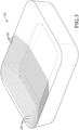
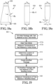
- FIGS. 1a and 1b One example of a pouch is shown in FIGS. 1a and 1b .
- each pouch 150 has a top portion 152 and a base portion 154 that is wider than top portion 152.
- the base portion 154 of the pouch 150 can be at least twice, at least three times, or at least four times wider than the top portion 152.
- the base portion 154 and the top portion 152 have approximately the same width.
- the width of the top portion 152 shown as Wi in FIG.
- 1a can be at least about 0.01, at least about 0.05, or at least about 0.10 inches and/or not more than about 0.25, not more than about 0.20, or not more than about 0.15 inches, or it can be in the range of from about 0.01 to about 0.25 inches, about 0.05 to about 0.20 inches, or from about 0.10 to about 0.15 inches.
- the width of the top portion 152 may be at least about 0.5, at least about 0.75, at least about 1, at least about 1.5 and/or not more than about 3, not more than about 2.5, not more than about 2, not more than about 1.5, or not more than about 1 inch, or it can be in the range of from about 0.5 to about 3 inches, about 0.75 to about 2.5 inches, about 1 to about 2 inches, or about 1 to about 1.5 inches.
- the width of the base portion 154 can be at least about 0.5, at least about 0.75, at least about 1, at least about 1.5 and/or not more than about 3, not more than about 2.5, not more than about 2, not more than about 1.5, or not more than about 1 inch, or it can be in the range of from about 0.5 to about 3 inches, about 0.75 to about 2.5 inches, about 1 to about 2 inches, or about 1 to about 1.5 inches.
- the height of the pouch 150 shown as H in FIG.
- 1b can be at least about 2, at least about 3, at least about 4, or at least about 4.5 inches and/or not more than about 12, not more than about 10, or not more than about 8 inches, or it can be in the range of from about 2 to about 12 inches, about 3 to about 10 inches, about 4 to about 8 inches.
- Pouches of other dimensions may also be suitable in various cases.
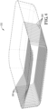
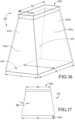
- the packages used may include trays.
- Trays generally have a top and a bottom and a general prism-like shape. Trays can have a square, rectangular, or elliptical cross-section, although other shapes may be suitable.
- a tray 250 is illustrated in FIGS. 2a-d . Each tray may have a single compartment for holding the foodstuff or other item to be heated, as shown in FIGS. 2a-d , or it may include two or more compartments at least partially isolated from one another (not shown).
- tray 250 may have a top that is longer and wider than its bottom so that it has a generally trapezoidal shape, as generally shown in FIGS. 2a-d .
- the terms “length” and “width” refer to the longest and second longest, respectively, non-diagonal dimensions of a package.
- the length and width are measured at the largest cross-section (usually the top surface).
- the height is the shortest non-diagonal dimension measured perpendicular to the planes defined by the length and width.
- the length (L), width (W), and height (h) of tray 250 are shown in FIGS. 2a-d .
- the length (L) of each tray can be at least about 1, at least about 2, at least about 4, or at least about 6 inches and/or not more than about 18, not more than about 12, not more than about 10, not more than about 8, or not more than about 6 inches, or it can be in the range of from about 1 to about 18 inches, about 2 to about 12 inches, about 4 to about 10 inches, or about 6 to about 8 inches.
- the width (W) of each tray may be at least about 1 inch, at least about 2 inches, at least about 4 inches, at least about 4.5 inches, or at least 5 inches and/or not more than about 12 inches, not more than about 10 inches, not more than about 8 inches, or not more than 6 inches, or it can be in the range of from about 1 inch to about 12 inches, about 2 inches to about 10 inches, about 4 inches to about 8 inches, about 4.5 inches to about 6 inches, or about 5 inches to about 6 inches.
- Each tray may have a height (h) of at least about 0.5 inches, at least about 1 inch, at least about 1.5 inches and/or not more than about 8 inches, not more than about 6 inches, or not more than about 3 inches, or it can be in the range of from about 0.5 to about 8 inches, about 2 to about 6 inches, or 1.5 to 3 inches. Trays of other dimensions may also be suitable, depending on the particular application.
- the energy control element When the energy control element is part of the package, whether a pouch, a tray, or other container, it may cover all or a portion of the total surface area of the package.
- the energy control element may cover at least about 5, at least about 10, at least about 15, at least about 20, at least about 25, at least about 30, at least about 35, at least about 40, at least about 45, at least about 50, at least about 55, at least about 60, at least about 65, at least about 70, at least about 75, at least about 80, at least about 85, at least about 90, or at least about 95 percent of the total surface are of the package. In some cases, it may cover the entire surface area of the package.
- the energy control element may cover not more than about 95, not more than about 90, not more than about 85, not more than about 80, not more than about 75, not more than about 70, not more than about 65, not more than about 60, not more than about 55, not more than about 50, not more than about 45, not more than about 40, not more than about 35, not more than about 30, not more than about 25, not more than about 20, not more than about 15, not more than about 10, or not more than about 5 percent of the total surface area of the package.
- Energy control elements can be in any suitable shape.
- the energy control elements in the form of strips that are printed, labeled, laminated, or otherwise incorporated into all or a portion of the package.
- these types of energy control elements may be microwave enhancing elements and can be formed from a metallic material.
- Such energy control elements may be incorporated into or onto all or a portion of the package surface by printing, by lamination, or by application of labels that include the strips. In some cases, lamination may be used with flexible packages, while labels and printing may be used for rigid packaging.
- the energy control strips may be present on the lid, on the tray, or on both the tray and the lid.
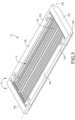
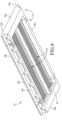
- An example of a tray 252 including a plurality of energy control strips 260 is shown in FIGS. 3 and 4 .
- the energy control strips 260 may cover more or less of the surface area of the tray 252, or may be positioned at different locations. Alternatively, or in addition, one or more of the energy control elements may be in a different shape, and/or the package may be a pouch or other type of container.
- the package may include at least 2, at least 3, at least 4, at least 5, at least 6, at least 7, at least 8, at least 9, at least 10, at least 11, or at least 12 or more strips that are spaced apart from one another along at least one surface of the package.
- Each of the strips may have a width, or second longest dimension, of at least about 1/64, at least about 1/32, or at least about 1/16 of an inch and/or not more than about 1/2, not more than about 1/4, or not more than about 1/8 of an inch.
- the size of each strip may be the same as the others, or one or more may have a different width.
- the strips may be spaced such that there are at least 2, at least 3, at least 4, at least 5, or at least 6 strips and/or not more than 15, not more than 14, not more than 12, or not more than 10 strips per the predominant wavelength of microwave energy to which the package is exposed during at least one heating step.
- the predominant wavelength of which microwave energy to which the package can be exposed during at least one heating step is at least about 1.4, at least about 1.5, at least about 1.6, or at least about 1.65 inches and/or not more than about 2, not more than about 1.9, not more than about 1.8, or not more than about 1.75 inches.
- the spacing between adjacent strips may be as wide as, or wider than, the width of each strip. Further, the spacing between sets of adjacent strips may be the same or different.
- the width of the open area between adjacent energy control strips can be at least about 10, at least about 15, at least about 20, at least about 25, at least about 30, at least about 35, at least about 40, at least about 45, or at least about 50 percent wider than the average width of the two adjacent energy control strips.
- the width of the open area between adjacent energy control strips can be not more than about 90, not more than about 85, not more than about 80, not more than about 75, not more than about 70, not more than about 65, or not more than about 60 percent wider than the average width of the two adjacent energy control strips.
- the packaged foodstuff is configured such that one or more foodstuffs in the package are positioned near the energy control element.
- the energy control element may be positioned such that at least about 5, at least about 10, at least about 15, at least about 20, at least about 25, at least about 30, at least about 35, at least about 40, at least about 45, at least about 50, at least about 55, at least about 60, at least about 65, at least about 70, at least about 75, at least about 80, at least about 85, at least about 90, at least about 95, or up to 100 percent of at least one foodstuff is positioned near the energy control element.
- part of the foodstuff may not be positioned near the energy control element.
- at least about 5, at least about 10, at least about 15, at least about 20, at least about 25, at least about 30, at least about 35, at least about 40, at least about 45, at least about 50, at least about 55, at least about 60, at least about 65, or at least about 75 percent of the foodstuff in a package may not be positioned near the energy control element. This may occur when, for example, the package includes two or more different foodstuffs in a single or multi-compartment tray or pouch.
- the package may include two or more energy control elements (of the same or a different type) each positioned near different types of foodstuff. In this way, the temperature and heating profile of different foodstuffs within a single package can be effectively controlled to achieve more efficient and uniform heating of the foodstuff or other item within the package.
- the energy control element may be part of a carrier used to secure and transport the articles through a microwave heating system.
- Carriers may be used in larger-scale microwave heating systems configured for the pasteurization or sterilization of packaged foodstuffs and other items.
- FIGS. 5-10 Several views of an exemplary carrier are provided in FIGS. 5-10 .
- the carrier 10 includes an outer frame 12, an upper support structure 14, and a lower support structure (not shown).
- the outer frame 12 comprises two spaced-apart side members 18a,b and two spaced-apart end members 20a,b.
- the first and second end members 20a,b may be coupled to and extend between opposite ends of first and second side members 18a,b to form outer frame 12.
- the frame may have a generally rectangular shape, as shown FIGS. 5 and 6 .
- first and second side members 18a,b each include respective support projections 22a,b that are configured to engage respective first and second convey line support members, which are represented by dashed lines 24a and 24b in FIG. 8 .
- the first and second support projections 22a,b of carrier 10 present first and second lower support surfaces 42a,b for supporting carrier 10 on first and second convey line support members 24a,b.
- Convey line support members 24a,b may be a moving convey line element such as, for example, a pair of chains (not shown) located on each side of carrier 10 as it moves through the microwave heating zone in a direction represented by the arrow in FIG. 8 .
- the first and second side members 18a,b and first and second end members 20a,b may be formed of any suitable material including, for example, a low loss material having a loss tangent of not more than about 10 -4 , not more than about 10 -3 , or not more than about 10 -2 , measured at 20°C.
- a low loss material having a loss tangent of not more than about 10 -4 , not more than about 10 -3 , or not more than about 10 -2 , measured at 20°C.
- Each of the side members 18a,b and end members 20a,b may be formed of the same material, at least one may be formed of a different material.
- suitable low loss tangent materials may include, but are not limited to, various polymers and ceramics.
- the low loss tangent material may be a food-grade material.
- the low loss material when it is a polymeric material, it may have a glass transition temperature of at least about 80°C, at least about 100°C, at least about 120°C, at least about 140°C, or at least about 160°C, at least about 165°C, in order to withstand the elevated temperatures to which the carrier may be exposed during heating of the articles.
- Suitable low loss polymers can include, for example, polytetrafluoroethylene (PTFE), polysulfone, polynorbornene, polycarbonate (PC), acrylonitrile butadiene styrene (ABS), poly(methyl methacrylate) (PMMA), polyetherimide (PEI), polystyrene, polyvinyl alcohol (PVA), polyvinyl chloride (PVC), and combinations thereof.
- the polymer can be monolithic or it may be reinforced with glass fibers, such as, for example glass-filed PTFE ("TEFLON"). Ceramics, such as aluminosilicates, may also be used as the low loss material.
- the carrier 10 may include an upper support structure 14 and a lower support structure 16 for holding a group of articles within the carrier, while also permitting microwave energy pass through the carrier 10 to the articles.
- the upper and lower support structures 14, 16 may each include a plurality of support members extending between the end members 20a,b in a direction substantially parallel to the side members 18a,b. The support members may extend in a direction substantially perpendicular to the end members 20a,b.
- the terms "substantially parallel” and “substantially perpendicular” mean within 5° of being parallel or perpendicular, respectively.
- upper and lower support structures 14, 16 could include a grid member or substantially rigid sheets of a microwave transparent or semi-transparent material extending between the side members 18a,b and end members 20a,b. Additional details regarding the number, dimensions, and configurations of support structures 14 and 16 are provided in U.S. Patent Application Serial No. 15/284,173 , the entirety of which is incorporated herein by reference.
- one or more of the support members may be formed of a strong, electrically conductive material.
- Suitable electrically conductive materials can have a conductivity of at least about 10 3 Siemens per meter (S/m), at least about 10 4 S/m, at least about 10 5 S/m, at least about 10 6 S/m, or at least about 10 7 S/m at 20°C, measured according to ASTM E1004 (09).
- the electrically conductive material may have a tensile strength of at least about 50 MegaPascals (MPa), at least about 100 MPa, at least about 200 MPa, at least about 400 MPa, or at least about 600 MPa, measured according to ASTM E8/E8M-16a, and/or it may also have a yield strength of at least about 50, at least about 100, at least about 200, at least about 300, or at least about 400 MPa at 20°C, measured according to ASTM E8/E8M-16a.
- MPa MegaPascals
- the Young's Modulus of the electrically conductive material can be at least about 25 GigaPascals (GPa), at least about 50 GPa, at least about 100 GPa, or at least about 150 GPa and/or not more than about 1000 GPa, not more than about 750 GPa, not more than about 500 GPa, or not more than about 250 GPa, measured at 20°C, measured according to ASTM E111-04 (2010).
- the electrically conductive material may be metallic and, in some cases, may be a metal alloy.
- the metal alloy may include any mixture of suitable metal elements including, but not limited to, iron, nickel, and/or chromium.
- the electrically conductive material may comprise stainless steel and may be food-grade stainless steel.
- carrier 10 defines a cargo volume 32 for receiving and holding a plurality of articles 40.
- Cargo volume 32 is at least partially defined between the upper and lower support structures 14 and 16, which are vertically spaced apart from one another, and the side 18a,b and end 20a,b members.
- the articles received in cargo volume 32 may be in contact with and/or held in position by at least a portion of the individual support members present in the upper and lower support structures 14 and 16.
- Each of upper and lower support structures 14, 16 may be coupled to outer frame 12 in a removable or hinged manner so that at least one of the upper and lower support structures 14, 16 may be opened to load the articles 40 into carrier 10, closed to hold the articles 40 during heating, and opened again to unload the articles 40 from the carrier.
- the use of one or more longitudinal dividers 34 may create multiple compartments 36a-d within cargo volume 32 for receiving multiple rows of articles 40.
- Cargo volume 32 can be of any suitable size. In some cases, it can have a length measured between opposing internal surfaces of the first and second end members 20a,b, in the range of from about 0.5 to about 10 feet, about 1 to about 8 feet, or about 2 to about 6 feet.
- the cargo volume 32 may also have a width measured between opposing internal surfaces of the first and second side members 18a,b, in the range of from about 0.5 to about 10 feet, about 1 to about 8 feet, or from about 2 to about 6 feet.
- the height of the cargo volume which can be measured between opposing internal surfaces of the upper and lower support structures 14, 16, can be in the range of from about 0.50 to about 8, from about 0.75 to about 6, from about 1 to about 4, or from about 1.25 to about 2 inches.
- the cargo volume can have a total volume in the range of from about 2 to about 30 cubic feet, about 4 to about 20 cubic feet, about 6 to about 15 cubic feet, or about 6.5 to about 10 cubic feet.
- the carrier may further include at least one article spacing member 34 for adjusting the size and/or shape of the cargo volume 32.
- article spacing members include dividers 34, as shown in FIGS. 5 , 6 , and 10 , for dividing the cargo volume 32 into two or more compartments and vertical spacers, such as 38a,b shown in FIG. 9 , for adjusting the vertical height between the upper and lower support structures 14, 16.
- the article spacing member or members 34 may be permanently or removably coupled to the outer frame 12 or at least one of the upper and lower support structures 14, 16.
- an article spacing member such as a divider 34 or a vertical spacer 38
- an article spacing member such as a divider 34 or a vertical spacer 38
- it may be selectively inserted into and removed from the carrier 10 in order to change the size and/or shape of the cargo volume 32 so that the carrier 10 may hold many types of articles having different sizes and/or shapes. Further details regarding such carriers are provided in the ' 173 Application.
- the articles When loaded into a carrier as described herein, the articles are placed within the cargo volume 32 defined between the upper and lower support structures of the carrier.
- the cargo volume may be a single volume, or it may be divided into two or more compartments, such as 36a-d shown in FIG. 10 , using one or more dividers 34.
- the articles When loaded into the cargo volume 32, the articles may be placed in single rows along the length of the carrier. In some embodiments, the articles may be arranged in at least 2, at least 3, at least 4, at least 5, or at least 6 single rows and/or not more than 15, not more than 12, not more than 10, or not more than 8 single rows, or from 2 to 15 single rows, from 3 to 12 single rows, from 4 to 10 single rows, or from 5 to 8 single rows.
- each carrier may hold a total of at least 6, at least 8, at least 10, at least 12, at least 16, at least 18, at least 20, at least 24, at least 30 articles and/or not more than 100, not more than 80, not more than 60, not more than 50, or not more than 40 articles, or it can hold from 6 to 100 articles, from 8 to 80 articles, from 10 to 60 articles, from 12 to 50 articles, or from 18 to 40 articles.
- Articles can be loaded into the carrier in any suitable manner, including manually or using an automated device.
- each of the articles loaded into the cargo volume may be similar, or two or more articles may be different from one another.
- the articles loaded into a carrier may include a first group of a first type of article and a second group of a second type of article, with the first type of article and second type of article having different packages and/or different types of contents within the packages.
- the articles may be spaced apart from one another within the carrier, or one or more articles may contact at least a portion of one or more other articles.
- the average distance between consecutive edges of adjacent articles loaded in the carrier can be not more than about 1 inch, not more than about 0.75 inches, not more than about 0.5 inches, not more than about 0.25 inches, or not more than about 0.1 inch. There may be no gaps between the articles such that adjacent articles are in contact with one another when loaded into the carrier, or at least a portion of adjacent articles may overlap horizontally.
- the particular arrangement of the articles within the cargo space may depend, at least in part, on the shape of the articles.
- the articles may be arranged in a nested configuration.
- FIG. 11 provides a side view of one row of articles 40a-f arranged in a nested configuration.
- adjacent articles have opposite orientations.
- the articles 40a-f loaded into the carrier are sequentially oriented in the direction of travel, indicated by the arrow 50 in FIG. 11 , in a top down, top up, top down, top up configuration.
- the bottom of the second article 40b is oriented between the top of the first article 40a and the top of the third article 40c.
- the tops of one set of alternating articles 40b, d, f and the bottoms of the other set of alternating articles 40a, c, e contact the upper support structure, while the bottoms and tops of each set of alternating articles contact the lower support structure when articles are loaded into the carri er.
- FIGS. 12 and 13 Two top views of a plurality of articles arranged in different nested configurations in a carrier are provided in FIGS. 12 and 13 .
- the tops of articles are marked with a "T”
- the bottoms articles are marked with a "B”
- the direction of travel of the carrier is shown by the arrow 50.
- the articles are arranged in several spaced-apart rows that are each arranged in a nested configuration
- FIG. 13 shows a fully nested article pattern, wherein the individual rows of nested articles are not spaced from one another and the articles are arranged in a nested configuration in both the longitudinal and transverse directions.
- articles as described herein may be heated in a microwave heating system used to pasteurize and/or sterilize the articles.
- pasteurization involves the rapid heating of a material to a minimum temperature between 80°C and 100°C, while sterilization involves heating the material to a minimum temperature between about 100°C and about 140°C.
- the microwave systems described herein may be used for pasteurization or for sterilization. In some cases, pasteurization and sterilization may take place simultaneously, or nearly simultaneously, so that the articles being processed are both pasteurized and sterilized by the heating system.
- microwave energy generally refers to electromagnetic energy having a frequency between 300 MHz and 30 GHz.
- the articles loaded into one or more carriers can initially be introduced into a thermalization zone 112, wherein the articles can be thermalized to a substantially uniform temperature. Once thermalized, the articles can optionally be passed through a pressure adjustment zone 114a before being introduced into a microwave heating zone 116. In microwave heating zone 116, the articles can be rapidly heated using microwave energy discharged into at least a portion of the heating zone by one or more microwave launchers, as generally shown as launchers 124 in FIG. 14b .
- the heated articles can then be passed through a holding zone 120, wherein the coldest portion of each article can be maintained at a temperature at or above a predetermined target temperature (e.g., a pasteurization or sterilization target temperature) for a specified amount of time.
- a predetermined target temperature e.g., a pasteurization or sterilization target temperature
- the articles can also be passed to a quench zone 122, wherein the temperature of the articles can be quickly reduced to a suitable handling temperature.
- the cooled articles can optionally be passed through a second pressure adjustment zone 114b before being removed from the system.
- the above-described thermalization, microwave heating, holding, and/or quench zones of the microwave system depicted in FIGS. 14a and 14b can be defined within a single vessel, or at least one of the above-described stages or zones can be defined within one or more separate vessels. Additionally, in some cases, at least one of the above-described steps can be carried out in a vessel that is at least partially filled with a liquid medium in which the articles being processed can be at least partially submerged. As used herein, the term "at least partially filled” denotes a configuration where at least 50 percent of the volume of the specified vessel is filled with a liquid medium.
- the volume of at least one of the vessels used in the thermalization zone, the microwave heating zone, the holding zone, and the quench zone can be at least about 75 percent, at least about 90 percent, at least about 95 percent, or 100 percent filled with a liquid medium.
- the liquid medium used may be any suitable liquid medium.
- the liquid medium may have a dielectric constant greater than the dielectric constant of air and, in one embodiment, can have a dielectric constant similar to the dielectric constant of the articles being processed.
- Water or a liquid medium comprising water
- the liquid medium may also include one or more additives, such as, for example, oils, alcohols, glycols, and salts in order to alter or enhance its physical properties (e.g., boiling point) at the conditions of operation.
- the microwave heating systems as described herein may include at least one conveyance system (not shown in FIGS. 14a and 14b ) for transporting the articles through one or more of the processing zones described above.
- suitable conveyance systems can include, but are not limited to, plastic or rubber belt conveyors, chain conveyors, roller conveyors, flexible or multi-flexing conveyors, wire mesh conveyors, bucket conveyors, pneumatic conveyors, screw conveyors, trough or vibrating conveyors, and combinations thereof. Any suitable number of individual convey lines can be used with the conveyance system, and the convey line or lines may be arranged in any suitable manner within the vessels.
- the loaded carriers introduced into the microwave system depicted in FIGS. 14a and 14b are initially introduced into a thermalization zone 112, wherein the articles are thermalized to achieve a substantially uniform temperature.
- a substantially uniform temperature For example, at least about 85 percent, at least about 90 percent, at least about 95 percent, at least about 97 percent, or at least about 99 percent of all the articles withdrawn from the thermalization zone 112 have a temperature within about 5°C, within about 2°C, or within 1°C of one another.
- the terms "thermalize” and “thermalization” generally refer to a step of temperature equilibration or equalization.
- the articles in the carrier passing through the thermalization zone 112 can be at least partially submerged in the liquid during the passing.
- the liquid medium in the thermalization zone 112 can be warmer or cooler than the temperature of the articles passing therethrough and, in some cases, can have an average bulk temperature of at least about 30°C, at least about 35°C, at least about 40°C, at least about 45°C, at least about 50°C, at least about 55°C, or at least about 60°C and/or not more than about 100°C, not more than about 95°C, not more than about 90°C, not more than about 85°C, not more than about 80°C, not more than about 75°C, not more than about 70°C, not more than about 65°C, or not more than about 60°C.
- the thermalization step can be carried out under ambient pressure or it may be carried out in a pressurized vessel.
- thermalization may be performed at a pressure of at least about 1, at least about 2, at least about 5, or at least about 10 psig and/or not more than about 80, not more than about 50, not more than about 40, or not more than about 25 psig.
- the thermalization zone 112 is liquid filled and pressurized, the pressure may be in addition to any head pressure exerted by the liquid.
- Articles undergoing thermalization can have an average residence time in the thermalization zone 112 of at least about 30 seconds, at least about 1 minute, at least about 2 minutes, at least about 4 minutes and/or not more than about 20 minutes, not more than about 15 minutes, or not more than about 10 minutes.
- the articles withdrawn from the thermalization zone 112 can have an average temperature of at least about 20°C, at least about 25°C, at least about 30°C, at least about 35°C and/or not more than about 70°C, not more than about 65°C, not more than about 60°C, or not more than about 55°C.
- the carrier withdrawn from the thermalization zone may be passed through a pressure adjustment zone 114a before entering the microwave heating zone.
- the pressure adjustment zone 114a may be any zone or system configured to transition the carrier between an area of lower pressure and an area of higher pressure.
- the difference between the low and high pressure zones may vary depending on the system and can, for example, be at least about 1 psig, at least about 5 psig, at least about 10 psig, at least about 12 psig and/or not more than about 50 psig, not more than about 45 psig, not more than about 40 psig, or not more than about 35 psig.
- another pressure adjustment zone 114b may be present to transition the carrier between the microwave heating zone 116 or hold zone 120 and quench zone 122.
- the first pressure adjustment zone 114a can transition the carrier from a lower pressure thermalization zone to a higher pressure microwave heating zone, while the second pressure adjustment zone 114b may transition the carrier from a higher pressure holding zone 120 (or a higher-pressure portion of the quench zone) to a lower pressure quench zone 122, or portion thereof.
- the loaded carrier may be introduced into the microwave heating zone 116, wherein the articles may be heated using a portion of the microwave energy discharged into a microwave heating chamber via one or more microwave launchers.
- microwave heating systems of the present invention may employ microwave energy having a frequency within one or more of the above ranges, with a frequency of about 915 MHz being preferred.
- the microwave energy discharged into the microwave heating chamber may be polarized.
- the microwave heating zone may optionally utilize one or more other types of heat sources such as, for example, various conductive or convective heating methods of devices.
- At least about 50, at least about 55, at least about 60, at least about 65, at least about 70, at least about 75, at least about 80, at least about 85, at least about 90, or at least about 95 percent of the energy used to heat the articles can be microwave energy from a microwave source.
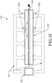
- the microwave heating zone 316 shown in FIG. 15 generally includes a microwave heating chamber 330, at least one microwave generator 332 for generating microwave energy, and a microwave distribution system 334 for directing at least a portion of the microwave energy from the generator or generators 332 to the microwave heating chamber 330.
- the system further comprises one or more microwave launchers 322 for discharging microwave energy into the interior of the microwave heating chamber 330.
- the microwave heating zone 316 may also include a convey system 340 having a convey line with a support for transport a plurality of carriers loaded with groups of articles through the microwave heating zone.
- Each microwave launcher 322 may be configured to emit a particular amount of microwave energy into the microwave heating chamber 330.
- each microwave launcher 322 may be configured to emit at least about 5, at least about 7, at least about 10, at least about 15 kW and/or not more than about 50, not more than about 40, not more than about 30, not more than about 25, not more than about 20, or not more than about 17 kW.
- each launcher 322 may emit the same amount of energy as one or more other launchers, or at least one launcher may emit a different (e.g., lower or higher) amount of energy, as compared to at least one of the other launchers.
- the total amount of energy discharged into the microwave heating chamber 330 can be at least about 25 kW, at least about 30 kW, at least about 35 kW, at least about 40 kW, at least about 45 kW, at least about 50 kW, at least about 55 kW, at least about 60 kW, at least about 65 kW, at least about 70 kW, or at least about 75 kW and/or not more than about 100 kW, not more than about 95 kW, not more than about 90 kW, not more than about 85 kW, not more than about 80 kW, not more than about 75 kW, not more than about 70 kW, or not more than about 65 kW.
- the system includes two or more microwave launchers 322, at least some of the launchers, shown as groups 322a and 322b in FIG. 15 , may be positioned on the same side of the microwave heating chamber 330. These same-side launchers 322a or 322b may be axially spaced from one another along the length of the microwave heating chamber, in a direction parallel to the direction of travel of the carrier 310 passing through the chamber.
- the microwave system may also include two or more same-side launchers that are laterally spaced from one another in a direction generally perpendicular to the direction of travel of the carriers through the chamber. Additionally, or in the alternative, the microwave heating system may also include at least two launchers positioned on opposite sides of the microwave chamber.
- These opposed or oppositely disposed launchers may be oppositely facing, such that launch openings of the launchers are substantially aligned, or staggered such that the launch openings of opposed launchers are axially and/or laterally spaced from each other.
- Each of the microwave launchers utilized in the microwave heating zone may be of any suitable configuration.
- Several exemplary microwave launchers are described with respect to FIGS. 16, 17 , and 18a-c .
- a microwave launcher 822 comprises a set of broader opposing sidewalls 832a,b and a set of narrower opposing end walls 834a,b, which collectively define a substantially rectangular launch opening 838.
- the launch opening 838 can have a width (Wi) and a depth (Di) that are defined by the lower terminal edges of sidewalls 832a,b and 834a,b, respectively.
- the depth (Di) of launch opening 838 is less than its width (Wi) and is typically oriented in a direction perpendicular to the direction of travel of the carriers moving through the microwave heating chamber.
- launch opening 838 may be elongated in the direction of travel of the carriers (or the direction of extension of the microwave chamber), so that the width of the launcher defined by the longer terminal edges of the sidewalls 832a,b are oriented parallel to the direction of travel (or the direction of extension), while the depth of the launcher defined by the shorter terminal edges of the end walls 834a,b are aligned substantially perpendicular to the direction of travel (or extension).
- FIG. 17 and 18a-c Views of one of sidewalls 832 and several examples of suitable end walls 834 are shown in FIG. 17 and 18a-c , respectively.
- at least one of the pair of sidewalls 832a,b and the pair of end walls 834a,b can be flared such that the inlet dimension (width W 0 or depth D 0 ) is smaller than the outlet dimension (width Wi or depth Di), as respectively illustrated in FIGS. 17 and 18a .
- the side and/or end walls define respective width and depth flare angles, ⁇ w and ⁇ d , as shown in FIGS. 17 and 18a .
- the width and/or depth flare angles ⁇ w and/or ⁇ d can be at least about 2°, at least about 5°, at least about 10°, or at least about 15° and/or not more than about 45°, not more than about 30°, or not more than about 15°.
- the values for the width and depth flare angles ⁇ w and ⁇ d can be the same, or each of ⁇ w and ⁇ d may have a different value.
- the end walls 838a,b of the microwave launcher 822 may have a depth flare angle ⁇ d that is smaller than the width flare angle ⁇ w .
- the depth flare angle ⁇ d can be not more than about 0°, such that the inlet depth D 0 and the outlet dimension Di of microwave launcher 822 are substantially the same, as shown in FIG. 18b , or the depth flare angle ⁇ d may be less than 0°, such that Di is smaller than D 0 , as shown in FIG. 18c .
- suitable microwave launchers are described in detail in the '516 Application.
- the launch opening or openings defined by one or more microwave launchers used in the present invention may be at least partially covered by a substantially microwave-transparent window for fluidly isolating the microwave heating chamber from the microwave launcher.
- the microwave transparent windows when present, may prevent fluid flow between microwave chamber and the microwave launchers, while still permitting a substantial portion of the microwave energy from the launchers to pass therethrough and into the microwave chamber.
- the windows may be formed of any suitable material, including, but not limited to, one or more thermoplastic or glass material such as glass-filled Teflon, polytetrafluoroethylene (PTFE), poly(methyl methacrylate (PMMA), polyetherimide (PEI), aluminum oxide, glass, and combinations thereof.
- each window may be at least about 4 mm, at least about 6 mm, at least about 8 mm, or at least about 10 mm and/or not more than about 20 mm, not more than about 16 mm, or not more than about 12 mm.
- Each window may be able to withstand a pressure difference of at least about 40 psig, at least about 50 psig, at least about 75 psi and/or not more than about 200 psig, not more than about 150 psig, or not more than about 120 psi without breaking, cracking, or otherwise failing.
- the articles may be heated so that the coldest portion of the articles achieves a target temperature.
- the target temperature achieved by the articles can be a sterilization or pasteurization target temperature of at least about 65°C, at least about 70°C, at least about 75°C, at least about 80°C, at least about 85°C, at least about 90°C, at least about 95°C, at least about 100°C, at least about 105°C, at least about 110°C, at least about 115°C, at least about 120°C, at least about 121°C, at least about 122°C and/or not more than about 130°C, not more than about 128°C, or not more than about 126°C.
- the temperature of an article refers to the temperature measured at the coldest portion of that article.
- the microwave heating chamber 330 may be at least partially liquid filled and at least a portion, or all, of the articles in the carrier may be submerged in the liquid medium during heating.
- the average bulk temperature of the liquid in the microwave heating chamber 330 may vary and, in some cases, can depend on the amount of microwave energy discharged into the microwave heating chamber.
- the average bulk temperature of the liquid in the microwave heating chamber 330 can be at least about 70°C, at least about 75°C, at least about 80°C, at least about 85°C, at least about 90°C, at least about 95°C, at least about 100°C, at least about 105°C, at least about 110°C, at least about 115°C, or at least about 120°C and/or not more than about 135°C, not more than about 132°C, not more than about 130°C, not more than about 127°C, or not more than about 125°C.
- the articles may be heated to the target temperature in a relatively short period of time, which can help minimize any damage or degradation of the articles.
- the average residence time of each article passing through the microwave heating zone 316 can be at least about 5 seconds, at least about 20 seconds, at least about 60 seconds and/or not more than about 10 minutes, not more than about 8 minutes, not more than about 5 minutes, not more than about 3 minutes, not more than about 2 minutes, or not more than about 1 minute.
- the minimum temperature of the articles heated in the microwave heating zone 316 can increase by at least about 5°C, at least about 10°C, at least about 15°C, at least about 20°C, at least about 30°C, at least about 40°C, at least about 50°C, at least about 75°C and/or not more than about 150°C, not more than about 125°C, or not more than about 100°C.
- the microwave heating chamber 330 can be operated at approximately ambient pressure. Alternatively, it may be a pressurized microwave chamber 330 that operates at a pressure that is at least 5 psig, at least about 10 psig, at least about 15 psig, or at least about 17 psig and/or not more than about 80 psig, not more than about 60 psig, not more than about 50 psig, or not more than about 40 psig above ambient pressure.
- ambient pressure refers to the pressure exerted by the fluid in the microwave heating chamber without the influence of external pressurization devices.
- the loaded carrier upon exiting the microwave heating zone 116, the loaded carrier may be passed to an optional holding zone 120, wherein the temperature of the articles can be maintained at or above a certain target temperature for a predetermined period of time.
- the temperature of the coldest part of the article can be held at a temperature at or above a predetermined minimum temperature of at least about 70°C, at least about 75°C, at least about 80°C, at least about 85°C, at least about 90°C, at least about 95°C, at least about 100°C, at least about 105°C, at least about 110°C, at least about 115°C, or at least about 120°C, at least about 121°C, at least about 122°C and/or not more than about 130°C, not more than about 128°C, or not more than about 126°C, for a period of time (or "hold period") of at least about 1 minute, at least about 2 minutes, or at least about 4 minutes and/or not more than about 20 minutes, not more than about 16 minutes, or not more than about 10 minutes.
- the heated articles which may be sufficient pasteurized or sterilized, exit the holding zone 120, may be introduced into a quench zone 122, wherein the articles are cooled as rapidly as possible via submersion in a cooled fluid.
- the quench zone 122 may reduce the external surface temperature of the articles by at least about 30°C, at least about 40°C, at least about 50°C and/or not more than about 100°C, not more than about 75°C, or not more than about 50°C in a time period of at least about 1 minute, at least about 2 minutes, at least about 3 minutes and/or not more than about 10 minutes, not more than about 8 minutes, or not more than about 6 minutes.
- any suitable fluid may be used in the quench zone 122 and, in some cases, the fluid may include a liquid similar to, or different than, the liquid used in the microwave heating zone 116 and/or the holding zone 120.
- the cooled articles can have a temperature of at least about 20°C, at least about 25°C, at least about 30°C and/or not more than about 70°C, not more than about 60°C, or not more than about 50°C.
- the cooled, treated articles can then be removed from microwave heating zone 100 for subsequent storage or use.
- Microwave heating systems of the present invention can be commercial-scale heating systems capable of processing a large volume of articles in a relatively short time.
- microwave heating systems as described herein can be configured to achieve an overall production rate of at least about 5 packages per minute, at least about 10 packages per minute, at least about 15 packages per minute per convey line, at least about 20 packages per minute per convey line, at least about 25 packages per minute per convey line, or at least about 30 packages per minute per convey line, measured as described in the '516 Application.
- Articles processed in a microwave pasteurization or sterilization system as described above may subsequently be obtained by a consumer, who may reheat the articles prior to consumption.
- the reheating step may include heating one or more articles in a smaller-scale consumer-type microwave oven. Depending on the size of the oven, the total number of articles heated at once can be not more than 5, not more than 4, not more than 3, or 2 or less.
- the microwave energy discharged by a consumer microwave oven is non-polarized or randomly polarized and has a frequency of about 2450 MHz. Additionally, articles re-heated in a consumer microwave oven are not secured in a carrier, as is done in a larger-scale pasteurization or sterilization system described previously.
- the articles reheated in a consumer microwave oven may be heated for a period of at least about 15 seconds, at least about 20 seconds, at least about 25 seconds, at least about 30 seconds, at least about 45 seconds, at least about 1 minute, at least about 1.5 minutes, at least about 2 minutes, at least about 2.5 minutes, or at least about 3 minutes and/or not more than about 10 minutes, not more than about 8 minutes, not more than about 7 minutes, not more than about 6.5 minutes, not more than about 6 minutes, not more than about 5.5 minutes, not more than about 5 minutes, not more than about 4.5 minutes, not more than about 4 minutes, not more than about 3.5 minutes, or not more than about 3 minutes.
- consumer microwave ovens are operated at atmospheric pressure and do not include liquid-filled chambers.
- the temperature achieved by the hottest portion of the foodstuff being reheated can be at least about 35, at least about 40, at least about 45, at least about 50, at least about 55, at least about 60, at least about 65, at least about 70, at least about 75, or at least about 80°C and/or not more than about 100, not more than about 95, not more than about 90, not more than about 85, not more than about 80, not more than about 75, not more than about 70, not more than about 65, not more than about 60, not more than about 55, not more than about 50, not more than about 45, or not more than about 40°C.
- the temperature achieved by the coldest portion of the foodstuff being reheated can be at least about 22, at least about 25, at least about 27, at least about 30, at least about 32, at least about 35, at least about 37, at least about 40, at least about 42, at least about 45, at least about 47, at least about 50, at least about 52, at least about 55, at least about 57, or at least about 60°C and/or not more than about 95, not more than about 90, not more than about 85, not more than about 80, not more than about 75, not more than about 70, not more than about 65, not more than about 60, not more than about 55, or not more than about 50°C.
- methods of designing a package for a particular foodstuff or other item to be heated in commercial microwave pasteurization/sterilization systems and at-home consumer microwave ovens as described herein are also provided.
- the major steps of one method 600 are shown in the flow chart provided in FIG. 18 .
- the first step of method 600 for designing a package including one or more energy control elements is to fill an initial package with a test material to form a test article, as shown by block 610.
- the initial package may be a commercially-available package, or it may be custom-made, and it may or may not already include one or more microwave energy control elements.
- the initial package used in this method may be a modified package that resulted from a previous trial.
- test material can include, for example, a sample of the exact foodstuff or other item which will ultimately be used to fill the package, or a substitute material used to simulate the foodstuff or other item.
- a suitable substitute test material is whey gel pudding, such as that commercially available from Ameriqual Group, LLC (Evansville, Indiana, USA).
- the initial package may be filled in any suitable manner. Generally, the initial package may be formed of conventional materials and may not include any type of energy control element, although situations where the initial package includes an energy control element are not excluded.
- the microwave heating system may be a large- or pilot-scale liquid-filled microwave heating system that utilizes polarized microwave energy, as described above with respect to FIGS. 14a and 14b , or it may be a lab-scale system designed to simulate the behavior of a larger-scale system.
- the test article may be heated in a consumer-type microwave oven that utilizes non-polarized or randomly polarized microwave energy.
- the temperature of the test material may be measured in one or more, preferably two or more, locations, as shown by block 612b in FIG. 18 .
- Such temperature measurement may be performed using any suitable instrument and, in some cases, may be performed using temperature probes positioned within the test material and sealed into the packages. In these cases, the temperature probe or probes would be placed into the packages along with the test material during the filling step, shown as block 610 in FIG. 18 .
- other types of temperature measurement devices may be used that may be positioned near or within the article after it has been filled.
- the article After the article has been heated to a target temperature, it may be removed from the microwave heating zone and cooled. As shown by block 614 in FIG. 18 , from the temperature measurements taken during the heating step, the location of at least one hot or cold spot within the package may be determined. In some cases, such a determination may be performed using temperature data obtained during the heating, as well as commercially available modeling software. In some cases, the location of the hot or cold spot may depend on the position of the article within a carrier, while, in other cases, it may not.
- the article may exhibit at least one hot spot, at least one cold spot, or at least one hot spot and at least one cold spot.
- the method 600 of designing a modified package further includes the step of creating a modified package including at least one energy control element by taking one or more of the following actions: (i) adding a microwave inhibiting element near a hot spot; (ii) adding a microwave enhancing element near a cold spot; (iii) removing a microwave inhibiting element from near a cold spot; and (iv) removing a microwave enhancing element from a hot spot.
- the microwave control element may be a selective microwave control element and may inhibit or enhance one type of microwave energy more than another.
- the modified package may be filled with the same test material used to fill the initial package and form the test article.
- the resulting modified article may again be heated in the same microwave heating system as the test article, and the same system may be used to measure the temperature of the test material during the heating.
- the temperature of the hot and/or cold spots previously determined may be measured and, after the heating step, the temperature measurements of the modified article may be compared with those taken during heating of the test article.
- the temperatures of the hot and/or cold spot is lower and/or higher, respectively, so that the variation between the temperature of the hot and/or cold spot and the rest of the material is less than it was during heating of the test article.
- the package may again be modified to include one or more energy control elements.
- Each of the steps 612 through 620 of method 600 may be repeated as many times as necessary to provide a final modified package which minimizes the presence of hot and cold spots and ensures more uniform heating of the material within the package.
Landscapes
- Physics & Mathematics (AREA)
- Electromagnetism (AREA)
- Engineering & Computer Science (AREA)
- Life Sciences & Earth Sciences (AREA)
- Food Science & Technology (AREA)
- Mechanical Engineering (AREA)
- Food Preservation Except Freezing, Refrigeration, And Drying (AREA)
- Constitution Of High-Frequency Heating (AREA)
- Electric Ovens (AREA)
- Seeds, Soups, And Other Foods (AREA)
Claims (15)
- Prozess zum Erhitzen einer Vielzahl von Gegenständen (40) in einem Mikrowellenheizsystem, der Prozess umfassend:(a) Laden einer Gruppe der Gegenstände in einen Träger (310), wobei jeder der Gegenstände eine mindestens teilweise mit mindestens einem Lebensmittel gefüllte Verpackung einschließt und jede Verpackung mindestens ein Energiesteuerelement einschließt;(b) Durchlaufen des beladenen Trägers durch eine Mikrowellenheizkammer (330) in einer Bewegungsrichtung entlang einer ersten Förderlinie;(c) Erzeugen von Mikrowellenenergie, wobei die Mikrowellenenergie polarisiert ist und eine Wellenlänge von nicht mehr als 1200 MHz aufweist;(d) Abfließen mindestens eines Abschnitts der Mikrowellenenergie in die Mikrowellenheizkammer während mindestens eines Abschnitts des Durchgangs; und(e) Erhitzen der Gegenstände unter Verwendung mindestens eines Abschnitts der in die Mikrowellenheizkammer abfließenden Mikrowellenenergie, um das Lebensmittel mindestens entweder zu sterilisieren oder zu pasteurisieren,wobei während des Erhitzens ein Abschnitt des Lebensmittels auf eine im Wesentlichen andere Temperatur und/oder mit einer im Wesentlichen anderen Erhitzungsgeschwindigkeit erhitzt wird, als der Abschnitt des Lebensmittels erhitzt worden wäre, wenn das Energiesteuerelement nicht vorhanden gewesen wäre.
- Prozess nach Anspruch 1, wobei sich die Erhitzungsgeschwindigkeit des Abschnitts des Lebensmittels um mindestens 2 °C/min von der Erhitzungsgeschwindigkeit unterscheidet, mit der der Abschnitt des Lebensmittels erhitzt worden wäre, wenn das Energiesteuerelement nicht vorhanden wäre und/oder wobei sich die Temperatur des Abschnitts des Lebensmittels um mindestens 5 °C von der Temperatur unterscheidet, auf die der Abschnitt des Lebensmittels erhitzt worden wäre, wenn das Energiesteuerelement nicht vorhanden wäre.
- Prozess nach Anspruch 1, wobei das Energiesteuerelement einen Suszeptor aufweist und der Abschnitt des Lebensmittels auf eine höhere Temperatur und/oder mit einer schnelleren Erhitzungsrate erhitzt wird, als der Abschnitt des Lebensmittels erhitzt worden wäre, wenn der Suszeptor nicht vorhanden wäre, und wobei die Erhitzungsrate des Abschnitts des Lebensmittels mindestens 10 °C/min beträgt und/oder wobei die von dem Abschnitt des Lebensmittels erreichte Temperatur mindestens 100 °C beträgt.
- Prozess nach Anspruch 1, wobei das Energiesteuerelement mindestens ein mikrowellenhemmendes Element umfasst und der Abschnitt des Lebensmittels auf eine niedrigere Temperatur und/oder mit einer langsameren Erhitzungsrate erhitzt wird, als wenn das Mikrowellenhemmungselement nicht vorhanden wäre, wobei die Erhitzungsrate des Abschnitts des Lebensmittels nicht mehr als 20 °C/min beträgt, und/oder wobei die von dem Abschnitt des Lebensmittels erreichte Temperatur weniger als etwa 125 °C beträgt.
- Prozess nach Anspruch 1, wobei das Energiesteuerelement eine Vielzahl von Energiesteuerstreifen umfasst, die sich auf mindestens einer Oberfläche der Verpackung befinden, wobei die Energiesteuerstreifen eine Breite im Bereich von etwa 1/16 Zoll bis etwa 1/8 Zoll aufweisen, wobei jeder der Energiesteuerstreifen voneinander beabstandet ist, um dadurch einen offenen Bereich zwischen benachbarten Energiesteuerstreifen zu definieren, und wobei die Breite des offenen Bereichs mindestens 25 Prozent größer ist als die durchschnittliche Breite der benachbarten Energiesteuerstreifen.
- Prozess nach Anspruch 1, wobei die Verpackungen mindestens teilweise mit zwei oder mehr verschiedenen Typen von Lebensmitteln gefüllt sind.
- Prozess nach Anspruch 1, wobei die auf die Gegenstände gerichtete Mikrowellenenergie eine Frequenz im Bereich von 850 bis 1050 MHz aufweist, wobei die Mikrowellenerwärmungskammer (330) mindestens teilweise mit einem flüssigen Medium gefüllt ist und wobei die Gegenstände während der Erwärmung mindestens teilweise in das flüssige Medium eingetaucht sind, und wobei das Mikrowellenerwärmungssystem eine Gesamtproduktionsrate von mindestens 5 Packungen pro Minute aufweist.
- Prozess nach Anspruch 1, wobei das Energiesteuerelement mindestens ein Mikrowellenhemmungselement einschließt, um zu verhindern, dass Mikrowellenenergie während der Erwärmung mindestens einen Abschnitt des Gegenstands erreicht.
- Prozess nach Anspruch 8, wobei das Mikrowellenhemmungselement so konfiguriert ist, dass es mindestens 5 Prozent der polarisierten Mikrowellenenergie reflektiert und für nichtpolarisierte oder zufällig polarisierte Mikrowellenenergie transparent ist.
- Prozess nach Anspruch 8, wobei die Verpackung eine obere Oberfläche und eine untere Oberfläche aufweist, wobei das Mikrowellenhemmungselement auf mindestens einem Abschnitt der oberen oder der unteren Oberfläche angeordnet ist, wobei das Mikrowellenhemmungselement mindestens 5 Prozent und weniger als 95 Prozent des gesamten Oberflächenbereichs der Verpackung bedeckt, wobei das Mikrowellenhemmungselement so konfiguriert ist, dass es verhindert, dass Mikrowellenenergie während des Erhitzens mindestens 10 Prozent und weniger als 90 Prozent des Gegenstands erreicht, wobei während des Erhitzens die Temperatur des Abschnitts des Gegenstands mindestens 5 °C niedriger ist als die Temperatur, auf die der Abschnitt des Gegenstands erhitzt worden wäre, wenn das Mikrowellenhemmungselement nicht vorhanden wäre und/oder wobei während des Erhitzens die Erhitzungsgeschwindigkeit des Abschnitts des Gegenstands mindestens 2 °C/min niedriger ist als die Erhitzungsgeschwindigkeit, mit der der Abschnitt des Gegenstands erhitzt worden wäre, wenn das Mikrowellenhemmungselement nicht vorhanden wäre.
- Prozess nach Anspruch 8, wobei einige der Gegenstände in dem Träger (310) eine Verpackung einschließen, die einen ersten Typ eines Mikrowellenhemmungselements aufweist, und einige der Gegenstände in dem Träger eine Verpackung einschließen, die einen zweiten Typ eines Mikrowellenhemmungselements aufweist.
- Prozess nach Anspruch 11, wobei mindestens einige der Gegenstände in dem Träger (310) eine Verpackung einschließen, die den ersten und den zweiten Typ eines Mikrowellenhemmungselements aufweist.
- Prozess nach Anspruch 8, wobei mindestens einige der Gegenstände in dem Träger (310) keine Verpackung einschließen, die ein Mikrowellenhemmungselement aufweist.
- Prozess nach Anspruch 8, wobei der Gegenstand ein Lebensmittel umfasst und ferner im Anschluss an Schritt (d) das Wiedererhitzen mindestens eines der Gegenstände in einem Mikrowellenofen unter Verwendung von Mikrowellenenergie umfasst, wobei der Gegenstand während des Wiedererhitzens nicht in einem Träger (310) befestigt ist, wobei die während des Erhitzens von Schritt (d) verwendete Mikrowellenenergie polarisiert ist, wobei die während des Wiedererhitzens verwendete Mikrowellenenergie nicht polarisiert oder zufällig polarisiert ist, und wobei mindestens eine der folgenden Bedingungen (i) bis (iii) erfüllt ist -(i) das Mikrowellenhemmungselement ist transparent für polarisierte Mikrowellenenergie und absorbiert oder reflektiert nicht polarisierte oder zufällig polarisierte Mikrowellenenergie;(ii) das Mikrowellenhemmungselement ist transparent für nicht polarisierte oder zufällig polarisierte Mikrowellenenergie und absorbiert oder reflektiert polarisierte Mikrowellenenergie; und(iii) das Mikrowellenhemmungselement ist so konfiguriert, dass es sowohl polarisierte als auch nicht polarisierte oder zufällig polarisierte Mikrowellenenergie absorbiert oder reflektiert, so dass sie durch es hindurchtreten kann.
- Prozess nach Anspruch 8, wobei die auf die Gegenstände gerichtete Mikrowellenenergie polarisierte Mikrowellenenergie ist und eine Frequenz im Bereich von 850 bis 1050 MHz aufweist, wobei die Mikrowellenerwärmungskammer (330) mindestens teilweise mit einem flüssigen Medium gefüllt ist und die Gegenstände während der Erwärmung mindestens teilweise in das flüssige Medium eingetaucht sind, und wobei das Mikrowellenerwärmungssystem eine Gesamtproduktionsrate von mindestens 5 Packungen pro Minute aufweist.
Applications Claiming Priority (2)
| Application Number | Priority Date | Filing Date | Title |
|---|---|---|---|
| US201762471654P | 2017-03-15 | 2017-03-15 | |
| PCT/US2018/022448 WO2018170137A1 (en) | 2017-03-15 | 2018-03-14 | Energy control elements for improved microwave heating of packaged articles |
Publications (4)
| Publication Number | Publication Date |
|---|---|
| EP3597006A1 EP3597006A1 (de) | 2020-01-22 |
| EP3597006A4 EP3597006A4 (de) | 2021-06-02 |
| EP3597006B1 true EP3597006B1 (de) | 2024-10-09 |
| EP3597006C0 EP3597006C0 (de) | 2024-10-09 |
Family
ID=63519795
Family Applications (1)
| Application Number | Title | Priority Date | Filing Date |
|---|---|---|---|
| EP18767080.7A Active EP3597006B1 (de) | 2017-03-15 | 2018-03-14 | Energiesteuerelemente für verbesserte mikrowellenheizung von verpackten artikeln |
Country Status (12)
| Country | Link |
|---|---|
| US (2) | US11032879B2 (de) |
| EP (1) | EP3597006B1 (de) |
| JP (1) | JP7261743B2 (de) |
| KR (1) | KR102559694B1 (de) |
| CN (1) | CN110771259B (de) |
| AU (1) | AU2018235948B2 (de) |
| BR (1) | BR112019019114A2 (de) |
| CA (1) | CA3056607A1 (de) |
| IL (1) | IL269342A (de) |
| MX (1) | MX2019011013A (de) |
| SG (1) | SG11201908537TA (de) |
| WO (1) | WO2018170137A1 (de) |
Families Citing this family (4)
| Publication number | Priority date | Publication date | Assignee | Title |
|---|---|---|---|---|
| EP3613260B1 (de) * | 2017-04-17 | 2024-01-17 | 915 Labs, Inc. | Mikrowellenunterstütztes sterilisations- und pasteurisationssystem mit verwendung synergistischer verpackungs-, träger- und auswerferkonfigurationen |
| CN111071630A (zh) * | 2018-10-22 | 2020-04-28 | 上海海洋大学 | 一种微波作用元件、微波食品包装及其加工方法 |
| USD950321S1 (en) * | 2020-02-12 | 2022-05-03 | Dart Industries Inc. | Storage container |
| US12390801B2 (en) * | 2021-05-11 | 2025-08-19 | Corning Incorporated | Wrapped green body carrier |
Family Cites Families (178)
| Publication number | Priority date | Publication date | Assignee | Title |
|---|---|---|---|---|
| US2485659A (en) | 1945-11-05 | 1949-10-25 | Ellis Foster Co | Delectric heating |
| US2500752A (en) | 1946-06-01 | 1950-03-14 | Gen Electric | High-frequency dielectric heating in a resonant chamber |
| US2743440A (en) | 1951-07-19 | 1956-04-24 | Henry J Riblet | Electromagnetic horn |
| US2769145A (en) | 1951-08-10 | 1956-10-30 | Gen Precision Lab Inc | Microwave power divider |
| US2946056A (en) | 1958-06-18 | 1960-07-19 | Hughes Aircraft Co | Electrically variable complex slot |
| US3092503A (en) | 1960-08-30 | 1963-06-04 | Oscar S Gray | Method and apparatus for sterilizing |
| US3365562A (en) | 1962-12-17 | 1968-01-23 | Cryodry Corp | Apparatus and process for microwave treatment |
| US3261140A (en) | 1963-08-30 | 1966-07-19 | Continental Can Co | Microwave sterilization and vacuumizing of products in flexible packages and apparatus therefor |
| FR1473832A (fr) | 1963-09-09 | 1967-03-24 | Atlas Werke Ag | Dispositif générateur de chaleur à partir d'énergie de micro-ondes, notamment pour la décongélation de produits alimentaires |
| US3398251A (en) | 1964-05-04 | 1968-08-20 | Cryodry Corp | Microwave heating of substances under hydrostatic pressure |
| US3437495A (en) | 1964-09-08 | 1969-04-08 | Cryodry Corp | Aseptic canning of foods having solid or semi-solid components |
| DE1565266A1 (de) | 1965-06-18 | 1970-02-05 | Fried. Krupp Gmbh, 4300 Essen | Querstrahler |
| CH426051A (de) | 1965-10-25 | 1966-12-15 | Patelhold Patentverwertung | Mikrowellenbehandlungstunnel |
| US3521186A (en) | 1967-06-26 | 1970-07-21 | Varian Associates | High power microwave attenuator employing a flow of lossy liquid |
| US3597240A (en) | 1969-05-28 | 1971-08-03 | Armour & Co | Enhanced dipolar effects in microwave processing |
| US3564458A (en) | 1969-10-28 | 1971-02-16 | Canadian Patents Dev | Branched waveguide transitions with mode filters |
| US3544923A (en) | 1969-10-30 | 1970-12-01 | Varian Associates | Microwave waveguide water load employing a quarter wave window of reduced characteristic impedance |
| US3610573A (en) | 1969-11-24 | 1971-10-05 | Carrier Corp | Valve structure |
| US3753651A (en) | 1970-08-27 | 1973-08-21 | Wave Energy Systems | Method and apparatus for surface sterilization |
| USRE30310E (en) | 1970-09-08 | 1980-06-17 | Alfa-Laval Ab | Method and apparatus for treating heat-sensitive products |
| US3657256A (en) | 1971-01-15 | 1972-04-18 | Great Lakes Chemical Corp | Dipyridylium quaternary dihalide halogen complexes |
| US3718082A (en) | 1971-04-20 | 1973-02-27 | S Lipoma | Apparatus for continuous electromagnetic sterilization |
| US3820549A (en) | 1972-11-30 | 1974-06-28 | Excel Engineering | Apparatus and method for radio frequency sterilization of cigars |
| US3814899A (en) | 1972-12-18 | 1974-06-04 | Gen Electric | Overtemperature control system |
| CH582842A5 (de) | 1974-07-15 | 1976-12-15 | Vat Ag | |
| US3961569A (en) | 1974-08-15 | 1976-06-08 | The United States Of America As Represented By The Secretary Of The Army | Apparatus for continuous microwave sterilization of food in pouches |
| US3945170A (en) | 1975-02-25 | 1976-03-23 | Brown Rodney F | Extension of shelf life of fresh produce |
| US4071833A (en) | 1976-10-15 | 1978-01-31 | Ford Motor Company | Apparatus for coupling coaxial transmission line to rectangular waveguide |
| US4168418A (en) | 1977-09-07 | 1979-09-18 | Bird Leslie L | Rendering of material such as meat |
| FR2458772A1 (fr) | 1979-06-08 | 1981-01-02 | Cgr Mev | Dispositif dessicateur a micro-ondes destine au sechage de produits en grains |
| JPS5648876A (en) | 1979-09-26 | 1981-05-02 | Mitsubishi Monsanto Chem Co | Thermal sterilization by microwave heating |
| US4282887A (en) | 1979-10-11 | 1981-08-11 | Rca Corporation | Ridge-waveguide applicator for treatment with electromagnetic energy |
| SE441640B (sv) | 1980-01-03 | 1985-10-21 | Stiftelsen Inst Mikrovags | Forfarande och anordning for uppvermning medelst mikrovagsenergi |
| GB2076229B (en) | 1980-05-01 | 1984-04-18 | Plessey Co Ltd | Improvements in or relating to apparatus for microwave signal processing |
| US4301347A (en) | 1980-08-14 | 1981-11-17 | General Electric Company | Feed system for microwave oven |
| US4336434A (en) | 1980-08-15 | 1982-06-22 | General Electric Company | Microwave oven cavity excitation system employing circularly polarized beam steering for uniformity of energy distribution and improved impedance matching |
| US4518618A (en) | 1982-02-12 | 1985-05-21 | The Clorox Company | Food coating compositions for foods cooked by microwave |
| JPS58142184A (ja) | 1982-02-19 | 1983-08-23 | 大阪瓦斯株式会社 | 乾燥装置 |
| US4464554A (en) | 1982-08-25 | 1984-08-07 | General Electric Company | Dynamic bottom feed for microwave ovens |
| US4446349A (en) | 1983-01-03 | 1984-05-01 | General Electric Company | Microwave phase shifting device |
| EP0136453B2 (de) | 1983-08-10 | 1992-08-26 | Snowdrift Corp. N.V. | Verfahren und Vorrichtung zum Erwärmen von Objekten mittels Mikrowellen |
| NZ206150A (en) | 1983-11-04 | 1987-06-30 | Nz Government | Food processor; screw conveyor pitch wider in microwave chamber than preheating chamber |
| US4687895A (en) | 1984-07-30 | 1987-08-18 | Superwave Technology, Inc. | Conveyorized microwave heating system |
| DE3432341A1 (de) | 1984-09-03 | 1986-03-06 | Hermann Berstorff Maschinenbau Gmbh, 3000 Hannover | Verfahren und anlage zum kontinuierlichen pasteurisieren von lebensmitteln |
| US4573660A (en) | 1984-11-23 | 1986-03-04 | Anchor/Darling Valve Company | Double disc gate valve |
| US4839142A (en) | 1985-09-30 | 1989-06-13 | Charm Stanley E | High temperature, short time heating system and method of sterilizing or pasteurizing heat sensitive biological fluids |
| US4613836A (en) | 1985-11-12 | 1986-09-23 | Westinghouse Electric Corp. | Device for switching between linear and circular polarization using rotation in an axis across a square waveguide |
| SE451656B (sv) | 1986-02-11 | 1987-10-19 | Alfastar Ab | Anordning for uppvermning medelst mikrovagsenergi |
| SE452086B (sv) | 1986-03-03 | 1987-11-09 | Alfastar Ab | Metod for vermning med mikrovagor |
| US5101084A (en) | 1986-09-02 | 1992-03-31 | The Pillsbury Company | Microwave food products and method of their manufacture and heating |
| DE3724214C2 (de) | 1986-10-04 | 1989-01-12 | Hans Stamer | Verfahren zur herstellung von lagerfaehigen, ganze fruechte enthaltenden fruchtzubereitungen ohne konservierungsstoffe und deren verwendung |
| US4874917A (en) | 1986-10-23 | 1989-10-17 | The Pillsbury Company | Microwave food product and method of manufacture |
| US4808782A (en) | 1986-11-26 | 1989-02-28 | Toppan Printing Co., Ltd. | Microwave irradiating sterilization process |
| US4779649A (en) | 1987-01-30 | 1988-10-25 | Huntington Mechanical Laboratories, Inc. | Gate valve with camming wedge, pressure equalizer, and replaceable bleeder valve |
| AT390734B (de) | 1987-04-14 | 1990-06-25 | Katschnig Helmut | Vorrichtung zum abtoeten bzw. inaktivieren von eiweiss- bzw. nukleinsaeurehaeltigen organismen |
| EP0287760A1 (de) | 1987-04-15 | 1988-10-26 | HERMANN BERSTORFF Maschinenbau GmbH | Vorrichtung zum gleichmässigen und schnellen Erwärmen, Pasteurisieren oder Sterilisieren von Lebensmitteln oder dergleichen |
| US4927991A (en) * | 1987-11-10 | 1990-05-22 | The Pillsbury Company | Susceptor in combination with grid for microwave oven package |
| NL8802714A (nl) | 1987-11-24 | 1989-06-16 | Stork Amsterdam | Werkwijze voor het in continue doorstroming thermisch behandelen van een produktmengsel bestaande uit een vloeistof met daarin opgenomen vaste delen. |
| FR2627634B1 (fr) | 1988-02-23 | 1990-03-23 | Thomson Csf | Diviseur de puissance en guide d'ondes |
| IT1217778B (it) | 1988-06-03 | 1990-03-30 | Barilla Flli G & R | Procedimento per la stabilizzazione termica in continuo di prodotti alimentari confezionati |
| IT1224377B (it) | 1988-06-07 | 1990-10-04 | O M A C Srl | Metodo per la pastorizzazione e la sterilizzazione di prodotti alimentari con microonde e forno relativo |
| FR2645391B1 (fr) | 1989-04-04 | 1992-03-13 | Marzat Claude | Applicateur micro-ondes alimente sous incidence de brewster |
| US5108701A (en) | 1989-05-15 | 1992-04-28 | Cem Corporation | Process for rapid sterilization of biological media |
| US5049816A (en) | 1990-05-31 | 1991-09-17 | Texas Instruments Incorporated | Semiconductor substrate minority carrier lifetime measurements |
| US5228947A (en) | 1990-07-23 | 1993-07-20 | Trus Joist Macmillan, A Limited Partnership | Microwave curing system |
| US5185506A (en) * | 1991-01-15 | 1993-02-09 | Advanced Dielectric Technologies, Inc. | Selectively microwave-permeable membrane susceptor systems |
| US5326530A (en) | 1991-01-22 | 1994-07-05 | Iit Research Institute | Energy-efficient electromagnetic elimination of noxious biological organisms |
| US5160819A (en) | 1991-03-11 | 1992-11-03 | Alcan International Limited | Microwave tunnel oven having means for generating higher order modes in loads |
| US5396919A (en) | 1993-08-18 | 1995-03-14 | Everlasting Valve Co., Inc. | Rotating disc valve |
| US5436432A (en) | 1993-10-14 | 1995-07-25 | Cyr; Samuel A. | Microwave autoclave apparatus |
| US5410283A (en) | 1993-11-30 | 1995-04-25 | Xerox Corporation | Phase shifter for fine tuning a microwave applicator |
| IT1262686B (it) | 1993-12-09 | 1996-07-04 | O M A C Societa Per Azioni | Metodo e impianto per la pastorizzazione o la sterilizzazione di prodotti alimentari solidi o liquidi mediante microonde. |
| US5379983A (en) | 1993-12-21 | 1995-01-10 | Vat Holding Ag | Shut-off valves for pipelines |
| IT1270063B (it) | 1994-07-04 | 1997-04-28 | Rossi & Catelli Spa | Autoclave per la cottura e la sterilizzazione in continuo di prodotti alimentari in genere |
| US5546849A (en) | 1995-03-06 | 1996-08-20 | North Carolina State University | Hydrostatic heating apparatus |
| US5864123A (en) | 1995-06-02 | 1999-01-26 | Keefer; Richard M. | Smart microwave packaging structures |
| US5903241A (en) | 1995-08-28 | 1999-05-11 | Bhattacharyya; Arun K. | Waveguide horn with restricted-length septums |
| WO1997016984A1 (fr) | 1995-11-10 | 1997-05-15 | Kabushiki Kaisha Kumeta Seisakusyo | Sterilisateur a hyperfrequences |
| US6153868A (en) | 1996-01-19 | 2000-11-28 | Groupe Danone | Microwave application device, particularly for baking products on a metal carrier |
| JPH11186363A (ja) | 1997-12-24 | 1999-07-09 | Shin Etsu Handotai Co Ltd | 半導体製造装置 |
| US6657173B2 (en) | 1998-04-21 | 2003-12-02 | State Board Of Higher Education On Behalf Of Oregon State University | Variable frequency automated capacitive radio frequency (RF) dielectric heating system |
| US6844534B2 (en) * | 1998-06-23 | 2005-01-18 | Micvac Ab | Process for microwave cooking and vacuum packing of food |
| CN1146305C (zh) | 1998-12-17 | 2004-04-14 | 个人化学第-乌普萨拉有限公司 | 进行化学反应的微波装置和方法 |
| US6034361A (en) | 1999-04-28 | 2000-03-07 | Hewlett-Packard Company | System for monitoring the progress of a chemical reaction in a microwave-assisted heating system |
| JP2000327048A (ja) * | 1999-05-20 | 2000-11-28 | Otsuka Chem Co Ltd | 密封包装物品の加熱方法、密封包装物品収容ケース及び密封包装物品加熱装置 |
| DE19925493C1 (de) | 1999-06-04 | 2001-01-18 | Fraunhofer Ges Forschung | Linear ausgedehnte Anordnung zur großflächigen Mikrowellenbehandlung und zur großflächigen Plasmaerzeugung |
| US6888115B2 (en) | 2000-05-19 | 2005-05-03 | Industrial Microwave Systems, L.L.C. | Cascaded planar exposure chamber |
| JP3950633B2 (ja) | 2001-01-26 | 2007-08-01 | 日本電波工業株式会社 | 水晶発振器 |
| US7154103B2 (en) | 2001-04-02 | 2006-12-26 | Mitec Incorporated | Method of providing extended shelf life fresh meat products |
| US6612546B2 (en) | 2001-08-01 | 2003-09-02 | Varian, Inc. | Gate valve with delayed retraction of counter plate |
| AU2002335641B2 (en) | 2001-08-16 | 2006-04-27 | Communications & Power Industries Llc | Waveguide foreign object damage prevention window |
| DE10157601B4 (de) | 2001-11-26 | 2011-06-01 | Dieffenbacher Gmbh + Co. Kg | Vorrichtung zur Erwärmung von Pressgut bei der Herstellung von Werkstoffplatten |
| ITTV20020120A1 (it) | 2002-10-18 | 2004-04-19 | S M C Srl | Tunnel per il condizionamento di prodotti alimentari |
| DE10260743B4 (de) | 2002-12-23 | 2008-05-15 | Outokumpu Oyj | Verfahren und Anlage zum thermischen Behandeln von körnigen Feststoffen in einem Wirbelbett |
| FR2854022A1 (fr) | 2003-04-16 | 2004-10-22 | Rimm Technologies Corp N V | Dispositif a micro-ondes ou a radio-frequences comprenant trois generateurs decouples |
| AU2004203861A1 (en) | 2003-08-13 | 2005-03-03 | Mars, Incorporated | Method and apparatus for continuous processing of packaged products |
| US7119313B2 (en) | 2003-09-08 | 2006-10-10 | Washington State University Research Foundation | Apparatus and method for heating objects with microwaves |
| US7582852B2 (en) * | 2004-03-12 | 2009-09-01 | Acp, Inc. | Microwave intensification system for rapid, uniform processing of food items |
| US8087407B2 (en) | 2004-03-23 | 2012-01-03 | Middleby Corporation | Conveyor oven apparatus and method |
| JP2005295848A (ja) | 2004-04-08 | 2005-10-27 | Daiwa Can Co Ltd | マイクロ波による包装食品の殺菌方法 |
| US7887864B2 (en) | 2004-07-23 | 2011-02-15 | Kraft Foods Global Brands Llc | Heat-stable concentrated milk product |
| CA2575996C (en) | 2004-08-06 | 2013-10-22 | Pactiv Corporation | Microwaveable laminate container |
| US20060102622A1 (en) | 2004-11-12 | 2006-05-18 | Daniel Gregoire | Uniform microwave heating method and apparatus |
| NZ553749A (en) | 2004-11-12 | 2011-08-26 | Univ North Carolina State | Methods and apparatuses for thermal treatment of foods and other biomaterials, and products obtained thereby |
| WO2006073909A2 (en) | 2005-01-03 | 2006-07-13 | Mackay Jeffrey H | Tunnel for conditioning of products, especially for sterilization of food in prepackaged containers |
| US7110313B2 (en) | 2005-01-04 | 2006-09-19 | Taiwan Semiconductor Manufacturing Company, Ltd. | Multiple-time electrical fuse programming circuit |
| US20060231550A1 (en) | 2005-01-20 | 2006-10-19 | Wendel Thomas D | Product guidance system for continuous conveyor microwave oven |
| ATE523096T1 (de) * | 2005-02-10 | 2011-09-15 | Micropast Gmbh | Verfahren zum haltbarmachen von lebensmitteln |
| US7470876B2 (en) | 2005-12-14 | 2008-12-30 | Industrial Microwave Systems, L.L.C. | Waveguide exposure chamber for heating and drying material |
| EP1993928B1 (de) | 2006-03-10 | 2011-05-11 | Graphic Packaging International, Inc. | Behälter mit interaktivem mikrowellennetz |
| WO2007108674A1 (en) | 2006-03-21 | 2007-09-27 | Sonder Food Systems B.V. | Device for pasteurizing a mass of foodstuff |
| AT503448B1 (de) | 2006-03-29 | 2007-10-15 | Leica Mikrosysteme Gmbh | Gerät zur präparation biologischer proben für die elektronenmikroskopie |
| US8063344B2 (en) * | 2006-04-27 | 2011-11-22 | Graphic Packaging International, Inc. | Microwave energy interactive food package |
| CA2654333A1 (en) * | 2006-06-08 | 2007-12-13 | Nestec S.A. | Microwave food packaging |
| EP2055146B1 (de) | 2006-07-10 | 2013-11-20 | Goji Limited | Nahrungsmittelzubereitung |
| BRPI0806685B1 (pt) * | 2007-01-22 | 2019-07-09 | Graphic Packaging International, Llc | Construção para aquecimento de um produto alimentício em um forno de microondas |
| US7518092B2 (en) | 2007-03-15 | 2009-04-14 | Capital Technologies, Inc. | Processing apparatus with an electromagnetic launch |
| JP2008253202A (ja) | 2007-04-05 | 2008-10-23 | Ryoso:Kk | 食品の加熱処理方法と装置 |
| BRPI0701638B1 (pt) | 2007-04-24 | 2016-10-11 | Petróleo Brasileiro S A Petrobras | reator e sistema para hidroprocessamento assistido por microondas |
| US20080299276A1 (en) | 2007-05-31 | 2008-12-04 | Clint Eubanks | Split-Stream Processing Methods and Systems for Multi-Phase Food Products |
| US7863997B1 (en) | 2007-06-22 | 2011-01-04 | The Ferrite Company, Inc. | Compact tuner for high power microwave source |
| JP5391199B2 (ja) | 2007-08-28 | 2014-01-15 | テキサス テック ユニヴァーシティー システム | 食品保存方法及びシステム |
| US7996306B2 (en) | 2007-09-10 | 2011-08-09 | Yahoo! Inc. | System and method for payment over a series of time periods in an online market with budget and time constraints |
| JP4832403B2 (ja) | 2007-10-23 | 2011-12-07 | 大和製罐株式会社 | 円偏波による食品の連続均一加熱装置 |
| EP2225078A1 (de) | 2007-11-29 | 2010-09-08 | Dow Global Technologies Inc. | Verfahren zur steuerung und optimierung der mikrowellenerhitzung von kunststofffolien |
| US20090321428A1 (en) | 2008-06-30 | 2009-12-31 | Hyde Roderick A | Microwave oven |
| US8426784B2 (en) | 2008-07-18 | 2013-04-23 | Industrial Microwave Systems, Llc | Multi-stage cylindrical waveguide applicator systems |
| US7975983B2 (en) | 2008-08-19 | 2011-07-12 | Vetco Gray Inc. | System, method and apparatus for split gate valve with mechanically isolated seal surfaces |
| FI122203B (fi) | 2008-09-11 | 2011-10-14 | Raute Oyj | Aaltojohtoelementti |
| FI122204B (fi) | 2008-09-11 | 2011-10-14 | Raute Oyj | Laite tasomaisten tuotteiden mikroaaltolämmitystä varten |
| US8878109B2 (en) | 2008-09-19 | 2014-11-04 | Jeffrey H. Mackay | Package conveyor for continuous process microwave applicator |
| US9713340B2 (en) | 2008-09-23 | 2017-07-25 | North Carolina State University | Electromagnetic system |
| US8586899B2 (en) | 2008-11-24 | 2013-11-19 | Jeffrey H. Mackay | Apparatus and method for mass sterilization and pasteurization of food products |
| DK176962B1 (da) | 2008-12-01 | 2010-07-26 | Kongsberg Esco As | En dobbeltskive-skydeventil |
| JP2010139217A (ja) | 2008-12-15 | 2010-06-24 | Yamamoto Vinita Co Ltd | 加熱方法および加熱装置 |
| EP2384349A2 (de) | 2008-12-30 | 2011-11-09 | Basf Se | Mirkowellenunterstütztes härten von keramik/schaumstoff-formkörpern |
| JP2010166863A (ja) | 2009-01-23 | 2010-08-05 | Kansai Electric Power Co Inc:The | 真空解凍装置及び真空解凍方法 |
| JP2011021210A (ja) | 2009-07-13 | 2011-02-03 | Shimadzu Corp | Ecrプラズマ源およびecrプラズマ装置 |
| DE102009044496B4 (de) | 2009-11-11 | 2023-11-02 | Muegge Gmbh | Vorrichtung zur Erzeugung von Plasma mittels Mikrowellen |
| FR2954461A1 (fr) | 2009-12-21 | 2011-06-24 | Techdiss Technologies S L | Dispositif de traitement thermique en continu par microondes de produits, notamment alimentaires |
| CN102713379B (zh) | 2010-01-25 | 2014-03-26 | Vat控股公司 | 真空阀 |
| RU2012151908A (ru) | 2010-05-07 | 2014-06-20 | Пресско АйПи ЛЛК | Управление облучением посредством кубических уголковых отражателей |
| US8514034B2 (en) | 2010-10-15 | 2013-08-20 | Ut-Battelle, Llc | Radio frequency (RF) microwave components and subsystems using loaded ridge waveguide |
| JP2014518812A (ja) | 2011-04-25 | 2014-08-07 | グラフィック パッケージング インターナショナル インコーポレイテッド | マイクロ波エネルギー相互作用パウチ |
| US9955711B2 (en) | 2011-05-20 | 2018-05-01 | Jbt Food & Dairy Systems B.V. | Method and apparatus for increased product throughput capacity, improved quality and enhanced treatment and product packaging flexibility in a continuous sterilizing system |
| US9049751B1 (en) * | 2011-05-31 | 2015-06-02 | Nestec S.A. | Highly conductive microwave susceptors |
| TW201332871A (zh) | 2011-12-07 | 2013-08-16 | Intevac Inc | 高載量太陽能晶圓裝載裝置 |
| US9622298B2 (en) | 2012-03-14 | 2017-04-11 | Microwave Materials Technologies, Inc. | Microwave launchers providing enhanced field uniformity |
| WO2015048000A1 (en) * | 2013-09-26 | 2015-04-02 | Graphic Packaging International, Inc. | Laminates, and systems and methods for laminating |
| BR112016025733B1 (pt) | 2014-05-07 | 2023-02-28 | Washington State University | Aparelho e método para esterilização ou pasteurização |
| CN113925122A (zh) | 2014-09-17 | 2022-01-14 | 915 实验室有限公司 | 微波干馏系统,使用微波干馏系统加热食物产品的方法,以及配制用于微波干馏的食物产品 |
| CN107006082B (zh) * | 2014-10-23 | 2021-02-09 | H·D·小吉姆瑞 | 射频加热系统 |
| US11229095B2 (en) | 2014-12-17 | 2022-01-18 | Campbell Soup Company | Electromagnetic wave food processing system and methods |
| US20180111359A1 (en) | 2015-04-01 | 2018-04-26 | Printpack Illinois, Inc. | Multi-ply films for sterilization or pasteurization processes |
| US20170027196A1 (en) | 2015-07-30 | 2017-02-02 | Graphic Packaging International, Inc. | Sterilization of Food in Microwave Interactive Packages |
| GB2541373A (en) | 2015-08-05 | 2017-02-22 | Convenience Foods Ltd | Pasteurisation |
| MX2018001643A (es) | 2015-08-11 | 2018-05-17 | Graphic Packaging Int Llc | Paquete de calentamiento de microondas con proteccion polarizada. |
| US11284635B2 (en) | 2015-09-29 | 2022-03-29 | Red Bull Gmbh | System and method for pasteurizing foods |
| CN108140600B (zh) | 2015-10-01 | 2022-06-24 | 915实验室公司 | 在用于微波加热的托架中的制品的布置 |
| US20170142785A1 (en) | 2015-11-13 | 2017-05-18 | Bottle-Top Development Co. | Microwave heating system |
| EP3169141A1 (de) | 2015-11-13 | 2017-05-17 | Bottle-Top Development Co. | Mikrowellenheizsystem |
| US10258066B2 (en) | 2016-07-18 | 2019-04-16 | Washington State University | Microwave sterilization or pasteurization transport carriers and system |
| KR101907743B1 (ko) | 2016-08-05 | 2018-10-12 | 씨제이제일제당 (주) | 마이크로파 가열 전처리를 포함하는 가공 식품의 살균방법 |
| WO2018039112A1 (en) | 2016-08-23 | 2018-03-01 | Corning Incorporated | Rapid heating rate article and microwave methods |
| KR101849847B1 (ko) | 2016-08-30 | 2018-04-18 | 동서식품주식회사 | 열풍과 마이크로파를 이용한 식품 살균방법 및 살균장치 |
| MX2019003512A (es) | 2016-09-28 | 2019-06-20 | Printpack Illinois Inc | Estructuras multicapa, empaques y metodos de esterilizacion. |
| WO2018063468A1 (en) | 2016-09-28 | 2018-04-05 | Printpack Illinois, Inc. | Microwaved multi-ply structures, microwaved packages, and methods of sterilization |
| CN106658803B (zh) | 2016-10-20 | 2023-06-20 | 上海海洋大学 | 一种可调节微波能量分布的加热装置 |
| CN206077730U (zh) | 2016-10-20 | 2017-04-05 | 上海海洋大学 | 一种用于微波加热的水循环装置 |
| CN106472947A (zh) | 2016-10-20 | 2017-03-08 | 上海海洋大学 | 一种微波加热方法及智能微波系统 |
| CN206077729U (zh) | 2016-10-20 | 2017-04-05 | 上海海洋大学 | 一种可调节微波能量分布的加热装置 |
| CN206403121U (zh) | 2016-10-20 | 2017-08-15 | 上海海洋大学 | 一种用于工业化微波加热的食品加载装置 |
| KR101912779B1 (ko) | 2016-11-23 | 2018-11-01 | (주)에이치제이에프 | 육가공 제품의 연속 살균장치 및 방법 |
| CN206576184U (zh) | 2016-12-27 | 2017-10-24 | 青岛农业大学 | 一种水产品隧道微波蒸汽杀菌装置 |
| CN207305995U (zh) | 2017-04-14 | 2018-05-04 | 曲靖市麒麟区禽蛋副食品有限公司 | 一种瓶装饮料杀菌设备 |
| CN206994307U (zh) | 2017-05-24 | 2018-02-13 | 西南大学 | 一种微波杀菌系统 |
| CN107252030A (zh) | 2017-05-24 | 2017-10-17 | 西南大学 | 一种微波杀菌系统 |
| CN107535796A (zh) | 2017-10-10 | 2018-01-05 | 石河子大学 | 双带式微波快速杀菌装置 |
-
2018
- 2018-03-14 JP JP2019551279A patent/JP7261743B2/ja active Active
- 2018-03-14 BR BR112019019114A patent/BR112019019114A2/pt not_active Application Discontinuation
- 2018-03-14 KR KR1020197030182A patent/KR102559694B1/ko active Active
- 2018-03-14 SG SG11201908537T patent/SG11201908537TA/en unknown
- 2018-03-14 US US15/921,327 patent/US11032879B2/en active Active
- 2018-03-14 CA CA3056607A patent/CA3056607A1/en active Pending
- 2018-03-14 CN CN201880022094.9A patent/CN110771259B/zh active Active
- 2018-03-14 AU AU2018235948A patent/AU2018235948B2/en active Active
- 2018-03-14 MX MX2019011013A patent/MX2019011013A/es unknown
- 2018-03-14 WO PCT/US2018/022448 patent/WO2018170137A1/en not_active Ceased
- 2018-03-14 EP EP18767080.7A patent/EP3597006B1/de active Active
-
2019
- 2019-09-15 IL IL26934219A patent/IL269342A/en unknown
-
2021
- 2021-06-03 US US17/337,947 patent/US12309905B2/en active Active
Also Published As
| Publication number | Publication date |
|---|---|
| US20180270919A1 (en) | 2018-09-20 |
| EP3597006A4 (de) | 2021-06-02 |
| US11032879B2 (en) | 2021-06-08 |
| CN110771259A (zh) | 2020-02-07 |
| US12309905B2 (en) | 2025-05-20 |
| SG11201908537TA (en) | 2019-10-30 |
| EP3597006C0 (de) | 2024-10-09 |
| BR112019019114A2 (pt) | 2020-04-14 |
| CN110771259B (zh) | 2023-02-17 |
| IL269342A (en) | 2019-11-28 |
| AU2018235948A1 (en) | 2019-10-10 |
| KR102559694B1 (ko) | 2023-07-25 |
| WO2018170137A1 (en) | 2018-09-20 |
| KR20190137811A (ko) | 2019-12-11 |
| US20210289595A1 (en) | 2021-09-16 |
| MX2019011013A (es) | 2019-11-01 |
| EP3597006A1 (de) | 2020-01-22 |
| JP7261743B2 (ja) | 2023-04-20 |
| AU2018235948B2 (en) | 2023-05-18 |
| JP2020511759A (ja) | 2020-04-16 |
| CA3056607A1 (en) | 2018-09-20 |
Similar Documents
| Publication | Publication Date | Title |
|---|---|---|
| US12309905B2 (en) | Energy control elements for improved microwave heating of packaged articles | |
| AU2016331303B2 (en) | Convey line carrier for microwave heating | |
| US10813376B2 (en) | Convey line carrier for microwave heating | |
| US12016108B2 (en) | Microwave-assisted sterilization and pasteurization system using synergistic packaging, carrier and launcher configurations |
Legal Events
| Date | Code | Title | Description |
|---|---|---|---|
| STAA | Information on the status of an ep patent application or granted ep patent |
Free format text: STATUS: THE INTERNATIONAL PUBLICATION HAS BEEN MADE |
|
| PUAI | Public reference made under article 153(3) epc to a published international application that has entered the european phase |
Free format text: ORIGINAL CODE: 0009012 |
|
| STAA | Information on the status of an ep patent application or granted ep patent |
Free format text: STATUS: REQUEST FOR EXAMINATION WAS MADE |
|
| 17P | Request for examination filed |
Effective date: 20190925 |
|
| AK | Designated contracting states |
Kind code of ref document: A1 Designated state(s): AL AT BE BG CH CY CZ DE DK EE ES FI FR GB GR HR HU IE IS IT LI LT LU LV MC MK MT NL NO PL PT RO RS SE SI SK SM TR |
|
| AX | Request for extension of the european patent |
Extension state: BA ME |
|
| DAV | Request for validation of the european patent (deleted) | ||
| DAX | Request for extension of the european patent (deleted) | ||
| RIN1 | Information on inventor provided before grant (corrected) |
Inventor name: BEHRINGER, DAVID Inventor name: KIMREY, JR., HAROLD DAIL Inventor name: RAIDER, MATTHEW Inventor name: ZHANG, LI Inventor name: SPIZZIRRI, LORA NICOLETTE |
|
| A4 | Supplementary search report drawn up and despatched |
Effective date: 20210503 |
|
| RIC1 | Information provided on ipc code assigned before grant |
Ipc: H05B 6/64 20060101AFI20210426BHEP Ipc: B65D 81/34 20060101ALI20210426BHEP Ipc: H05B 6/78 20060101ALI20210426BHEP |
|
| GRAP | Despatch of communication of intention to grant a patent |
Free format text: ORIGINAL CODE: EPIDOSNIGR1 |
|
| STAA | Information on the status of an ep patent application or granted ep patent |
Free format text: STATUS: GRANT OF PATENT IS INTENDED |
|
| INTG | Intention to grant announced |
Effective date: 20240429 |
|
| GRAS | Grant fee paid |
Free format text: ORIGINAL CODE: EPIDOSNIGR3 |
|
| GRAA | (expected) grant |
Free format text: ORIGINAL CODE: 0009210 |
|
| STAA | Information on the status of an ep patent application or granted ep patent |
Free format text: STATUS: THE PATENT HAS BEEN GRANTED |
|
| AK | Designated contracting states |
Kind code of ref document: B1 Designated state(s): AL AT BE BG CH CY CZ DE DK EE ES FI FR GB GR HR HU IE IS IT LI LT LU LV MC MK MT NL NO PL PT RO RS SE SI SK SM TR |
|
| REG | Reference to a national code |
Ref country code: CH Ref legal event code: EP |
|
| REG | Reference to a national code |
Ref country code: DE Ref legal event code: R096 Ref document number: 602018075221 Country of ref document: DE |
|
| REG | Reference to a national code |
Ref country code: IE Ref legal event code: FG4D |
|
| U01 | Request for unitary effect filed |
Effective date: 20241104 |
|
| U07 | Unitary effect registered |
Designated state(s): AT BE BG DE DK EE FI FR IT LT LU LV MT NL PT RO SE SI Effective date: 20241113 |
|
| U20 | Renewal fee for the european patent with unitary effect paid |
Year of fee payment: 8 Effective date: 20250220 |
|
| PG25 | Lapsed in a contracting state [announced via postgrant information from national office to epo] |
Ref country code: IS Free format text: LAPSE BECAUSE OF FAILURE TO SUBMIT A TRANSLATION OF THE DESCRIPTION OR TO PAY THE FEE WITHIN THE PRESCRIBED TIME-LIMIT Effective date: 20250209 Ref country code: HR Free format text: LAPSE BECAUSE OF FAILURE TO SUBMIT A TRANSLATION OF THE DESCRIPTION OR TO PAY THE FEE WITHIN THE PRESCRIBED TIME-LIMIT Effective date: 20241009 |
|
| PG25 | Lapsed in a contracting state [announced via postgrant information from national office to epo] |
Ref country code: ES Free format text: LAPSE BECAUSE OF FAILURE TO SUBMIT A TRANSLATION OF THE DESCRIPTION OR TO PAY THE FEE WITHIN THE PRESCRIBED TIME-LIMIT Effective date: 20241009 |
|
| PG25 | Lapsed in a contracting state [announced via postgrant information from national office to epo] |
Ref country code: NO Free format text: LAPSE BECAUSE OF FAILURE TO SUBMIT A TRANSLATION OF THE DESCRIPTION OR TO PAY THE FEE WITHIN THE PRESCRIBED TIME-LIMIT Effective date: 20250109 |
|
| PG25 | Lapsed in a contracting state [announced via postgrant information from national office to epo] |
Ref country code: GR Free format text: LAPSE BECAUSE OF FAILURE TO SUBMIT A TRANSLATION OF THE DESCRIPTION OR TO PAY THE FEE WITHIN THE PRESCRIBED TIME-LIMIT Effective date: 20250110 |
|
| PG25 | Lapsed in a contracting state [announced via postgrant information from national office to epo] |
Ref country code: PL Free format text: LAPSE BECAUSE OF FAILURE TO SUBMIT A TRANSLATION OF THE DESCRIPTION OR TO PAY THE FEE WITHIN THE PRESCRIBED TIME-LIMIT Effective date: 20241009 |
|
| PGFP | Annual fee paid to national office [announced via postgrant information from national office to epo] |
Ref country code: GB Payment date: 20250213 Year of fee payment: 8 |
|
| PG25 | Lapsed in a contracting state [announced via postgrant information from national office to epo] |
Ref country code: RS Free format text: LAPSE BECAUSE OF FAILURE TO SUBMIT A TRANSLATION OF THE DESCRIPTION OR TO PAY THE FEE WITHIN THE PRESCRIBED TIME-LIMIT Effective date: 20250109 |
|
| PG25 | Lapsed in a contracting state [announced via postgrant information from national office to epo] |
Ref country code: SM Free format text: LAPSE BECAUSE OF FAILURE TO SUBMIT A TRANSLATION OF THE DESCRIPTION OR TO PAY THE FEE WITHIN THE PRESCRIBED TIME-LIMIT Effective date: 20241009 |
|
| PG25 | Lapsed in a contracting state [announced via postgrant information from national office to epo] |
Ref country code: SK Free format text: LAPSE BECAUSE OF FAILURE TO SUBMIT A TRANSLATION OF THE DESCRIPTION OR TO PAY THE FEE WITHIN THE PRESCRIBED TIME-LIMIT Effective date: 20241009 |
|
| PG25 | Lapsed in a contracting state [announced via postgrant information from national office to epo] |
Ref country code: CZ Free format text: LAPSE BECAUSE OF FAILURE TO SUBMIT A TRANSLATION OF THE DESCRIPTION OR TO PAY THE FEE WITHIN THE PRESCRIBED TIME-LIMIT Effective date: 20241009 |
|
| PLBE | No opposition filed within time limit |
Free format text: ORIGINAL CODE: 0009261 |
|
| STAA | Information on the status of an ep patent application or granted ep patent |
Free format text: STATUS: NO OPPOSITION FILED WITHIN TIME LIMIT |
|
| 26N | No opposition filed |
Effective date: 20250710 |
|
| PG25 | Lapsed in a contracting state [announced via postgrant information from national office to epo] |
Ref country code: MC Free format text: LAPSE BECAUSE OF FAILURE TO SUBMIT A TRANSLATION OF THE DESCRIPTION OR TO PAY THE FEE WITHIN THE PRESCRIBED TIME-LIMIT Effective date: 20241009 |
|
| REG | Reference to a national code |
Ref country code: CH Ref legal event code: H13 Free format text: ST27 STATUS EVENT CODE: U-0-0-H10-H13 (AS PROVIDED BY THE NATIONAL OFFICE) Effective date: 20251024 |