EP3595824B1 - Verfahren zum betreiben einer rollenrichtmaschine - Google Patents
Verfahren zum betreiben einer rollenrichtmaschine Download PDFInfo
- Publication number
- EP3595824B1 EP3595824B1 EP18713140.4A EP18713140A EP3595824B1 EP 3595824 B1 EP3595824 B1 EP 3595824B1 EP 18713140 A EP18713140 A EP 18713140A EP 3595824 B1 EP3595824 B1 EP 3595824B1
- Authority
- EP
- European Patent Office
- Prior art keywords
- straightening
- rollers
- flat material
- roller
- individual
- Prior art date
- Legal status (The legal status is an assumption and is not a legal conclusion. Google has not performed a legal analysis and makes no representation as to the accuracy of the status listed.)
- Active
Links
Images


Classifications
-
- B—PERFORMING OPERATIONS; TRANSPORTING
- B21—MECHANICAL METAL-WORKING WITHOUT ESSENTIALLY REMOVING MATERIAL; PUNCHING METAL
- B21D—WORKING OR PROCESSING OF SHEET METAL OR METAL TUBES, RODS OR PROFILES WITHOUT ESSENTIALLY REMOVING MATERIAL; PUNCHING METAL
- B21D1/00—Straightening, restoring form or removing local distortions of sheet metal or specific articles made therefrom; Stretching sheet metal combined with rolling
- B21D1/02—Straightening, restoring form or removing local distortions of sheet metal or specific articles made therefrom; Stretching sheet metal combined with rolling by rollers
Definitions
- the invention relates to a method for operating a roller straightening machine which has a number of upper straightening rollers and a number of lower straightening rollers, a flat metal material to be straightened, in particular a steel strip, being guided in a conveying direction between the straightening rollers and being straightened in the process.
- a method of the type mentioned and a corresponding roll straightener are from EP 0 551 658 B1 known.
- individual straightening rollers are adjusted in a targeted manner in order to achieve the required position of the rollers for the straightening process.
- the maximum overstretching is realized on just one straightening roller. Not all rolls are involved in the straightening process, but only a selection of them, various rolls are kept in stock.
- the EP 0 946 312 A1 likewise discloses a generic straightening method in which a non-rotating roller straightening unit is used. In advance of the actual straightening process, a simulation calculation is carried out offline, which includes possible variations of the straightening process.
- the FR 2 893 520 A1 , the FR 2 732 913 A1 and the CN 102 672 003 B show further straightening methods.
- the invention is therefore based on the object of developing a method of the type mentioned at the outset in such a way that a flat material with a high degree of flatness or evenness can be produced with a few straightening passes, even in the case of complex flatness errors.
- the determination of the individual parameters according to step a) above can additionally include an inspection of the flat material by an operator of the roller straightening machine. Furthermore, it can include determining material data of the flat material. Furthermore, it can be provided that the determination includes a definition of properties of the flat material after the straightening process, in particular a target stress profile in the flat material after the straightening process.
- Carrying out the straightening process according to step c) above can include a defined adjustment of the straightening rollers.
- the straightening strategy according to step b) above can include straightening the flat material with a plurality of straightening stitches.
- All straightening rollers are preferably brought into a predetermined individual delivery position by means of a separate adjustment element.
- the adjusting elements and/or the rotary drives of all straightening rollers are actuated by a control or regulation device.
- a proposed roller straightening machine not according to the invention, which has a number of upper straightening rollers and a number of lower straightening rollers, with a metallic flat material to be straightened being guided in a conveying direction between the straightening rollers and being straightened in the process, is characterized in that all straightening rollers have an individual adjustment element and have an individual rotary drive with which all straightening rollers can be adjusted and rotated independently of one another.
- the proposed procedure is therefore based on the consideration of first determining relevant data relating to the item to be straightened when carrying out the straightening process and reading or entering them into the machine control system.
- a straightening strategy for the material to be straightened is then determined.
- the straightening process takes place by activating machine functionalities to carry out the straightening process according to the straightening strategy determined.
- the straightening strategy is determined or calculated by a technological adjustment model.
- the determined or measured material data of the item to be straightened is in particular the type of alloy of the material; this also includes the thickness and strength of the material.
- the material is preferably steel sheets or strips.
- Types of defects or types of defects that were determined or established by a person through measurement or testing can also be recorded and entered.
- the data set can be read in on the basis of theoretical calculations or, as mentioned, by measurements or manual entries.
- the data set can include target specifications for the condition of the item to be straightened after straightening. A target stress profile and preceding and/or subsequent processing steps of the item can also be taken into account.
- the straightening strategy can be determined on the basis of the error types entered.
- the straightening strategy can be calculated separately or jointly for just a single straightening process or for several straightening passes.
- the straightening strategy of an individual item to be straightened can vary between two straightening passes; it can take into account previous and subsequent processing steps. If required, the straightening strategy can also be changed by the operating personnel.
- the adjustment of the straightening rollers takes place in such a way that the tension peaks have as constant a height as possible over the thickness of the flat material to be straightened.
- the machine functionalities mentioned are primarily about the main adjustment of the rollers, their tilting and swiveling and the bending, stretching and compression compensation.
- the adjustment of the individual straightening rollers is provided, as well as an individual drive for each individual straightening roller (with regard to their drive torques and speeds).
- the straightening rollers are preferably individually adjustable and individually drivable.
- this initially consists of a material database and the necessary inputs in order to carry out a numerical simulation of the deformation behavior of the metallic flat material under the influence of the straightening rollers. Only a short time of less than 1 second is required for such a simulation.
- the proposed roller straightening machine is characterized in that a control device is provided for individually controlling the existing machine functionalities, which sets the functionalities on the basis of a previously determined straightening strategy.
- the number and straightening roller sequence is specified or determined that allow overstretching, in particular on the basis of further data sets that go beyond the material data, such as defect type and production properties.
- the straightening strategy is ultimately a combination of specifications for the activation of machine functionalities, which are based on the calculation of the technological employment model. If several straightening stitches are required and/or complex and/or superimposed errors, the straightening strategy for the respective required straightening stitches of a single workpiece can deviate from one another and only lead to the optimum straightening result in total.
- this includes the actuators for setting and/or controlling forming parameters, in particular the speed and torque of the individual straightening rollers, the immersion depth of the individual straightening rollers, the contact force of the individual straightening rollers, the position specifications (pivoting/bending) of the individual straightening rolls and the main adjustment of all straightening rolls.
- Edge waves different fiber lengths from the strip edge to the middle of the strip
- center buckles different fiber lengths from the middle of the strip to the strip edge
- quarter buckles different fiber lengths in the longitudinal direction (strips)
- short-wave or long-wave appearance of the waves are edge waves (different fiber lengths from the strip edge to the middle of the strip), center buckles (different fiber lengths from the middle of the strip to the strip edge), quarter buckles (different fiber lengths in the longitudinal direction (strips)) and short-wave or long-wave appearance of the waves.
- the present invention is based on a technological adjustment model, which essentially consists of a material database and which, through further inputs, enables a complex calculation of the can carry out straightening process. It is precisely the consideration of the other inputs that leads to a significant improvement in the straightening process.
- the calculation of the technological adjustment model can also be extended to take previous production steps into account. If residual stress distributions from previous processing steps are known, these are also included in the technological calculations. This applies in particular to cooling, where different distributions are also taken into account in the workpiece surface (edges to center). These result from the physically necessary variable temperature distribution and the resulting different microstructure components in many steel brands. The information about this can be done via any data transfer, such. B. by means of a coupling with a cooling model.
- microstructure components e.g. austenite decomposition
- grain size distributions e.g. grain size distributions
- dislocation densities e.g. grain size distributions
- the information can also take place here via any data transfer, such as B. a coupling to a rolling model.
- the technological adjustment model can also incorporate specifications that take the following processing steps into account. If the straightening process involves a further processing step, e.g. B. welding or bending, so to maintain the flatness in these subsequent steps, the necessary stress profiles in the workpiece can be set in a targeted manner by defining the straightening strategy in the individual straightening passes.
- a further processing step e.g. B. welding or bending
- the straightening strategy converts the calculations generated from the technological adjustment model into specifications for carrying out the respective straightening pass by generating a combination of specifications for adjusting machine functionalities.
- the relevant machine functionalities are (as already mentioned) the main adjustment for all straightening rollers together (including tilting and pivoting), the individual straightening roller adjustment (for bending, stretching and compression compensation), the determination of the drive torques of each straightening roller and the straightening roller bending.
- the individual straightening roller adjustment in particular can set the individual immersion depth and thus provide a targeted straightening strategy within a straightening pass.
- the individual drive of each straightening roller enables the individual provision of torque for the straightening process.
- the maximum overstretching is realized on more than one straightening roller and preferably an even number of maximum overstretches is set; so the number of plastic strains and compressions becomes the same for both surfaces of the workpiece.
- the remaining alignment triangles are used to minimize the residual stress level.
- the straightening rollers are adjusted in such a way that the stress peaks have a constant height over the sheet thickness.
- the straightening rollers are adjusted in such a way that the stress peaks decrease from the middle of the workpiece thickness towards the surface.
- a smoothing pass (a special setting for leveling a thick sheet) can also be carried out, in which, after leveling, a switch is made to a reduced number of rollers or to leveling with the maximum number of rollers.
- the achievable flatness can also be set tailor-made for each workpiece, even with complex flatness errors.
- figure 1 is a schematic view of a roll straightening machine 1 having a plurality of upper straightening rolls and a plurality of lower straightening rolls.
- the upper straightening rollers follow one another in the conveying direction F, namely the straightening rollers 2, 3, 4 and 5.
- the lower straightening rollers are offset in the conveying direction F in relation to the upper straightening rollers and follow one another in the conveyor direction, namely the straightening rollers 6, 7, 8 and 9.
- a flat material 10 to be straightened is conveyed through the roller straightening machine 1 when the straightening rollers are fed onto the flat material 10 and rotated.
- the drive of the straightening rollers is shown schematically in the form of arrows (A).
- each of the straightening rollers 2 to 9 has a contact element, with those contact elements being denoted by 12 that act on the upper straightening rollers 2, 2, 3 and 5, and those contact elements that act on the lower straightening rollers 6, 7, 8 and 9 apply.
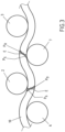
- FIG. 3 It can be seen how preferably the flat material 10 is acted upon by the straightening rollers in order to straighten it.
- an area P S of plastic compression is marked on the upper side of the flat material 10 and an area P D of plastic expansion on the underside of the flat material 10.
- an elastic area E is marked on the area of the neutral axis of the flat material 10.
- the lower straightening rollers 7 that follow in the conveying direction F are adjusted in such a way that an equally large forming force is exerted on the flat material 10 here as well, so that areas of plastic compression P S and plastic expansion P D again result, but now on the respective other sides of the flat material 10.
- FIG figure 2 The specific procedure for straightening the flat material 10 is shown in FIG figure 2 .
- a suitable sensor system 15 detects flatness errors in the flat material 10 before the straightening process and the measured values are made available in an area 16 as read-in or analyzed data.
- Said area 16 receives additional information from a data set 14 that contains data about the material and geometry of the flat material 10 to be straightened. Comprehensive information is thus available in area 16 which provides information about the type, the geometry and the degree of flatness of the flat material 10 .
- the adjustment model 17 is a mechanical substitute model for the flat material 10 to be straightened, in which the geometry is calculated by numerical simulation, which changes when the straightening rollers act upon it after the straightening process has been carried out results.
- Such simulation systems for the deformation of the material are known as such in the prior art and therefore do not need to be described in more detail at this point.
- One of the possible options is the calculation of the geometry and the stresses in the flat material 10 after the straightening process has been carried out using finite elements.
- a straightening strategy can thus be determined by appropriate calculation, which is made available in area 18 after the simulation calculation has been carried out.
- This straightening strategy includes guidelines for carrying out the straightening process for all planned straightening passes. This also results in the data required for the positioning of the straightening rollers and the actuation of the drives of the same.
- the data for adjusting the straightening rollers are then generated in area 19, which also include the corresponding values for the rotary drive of the rollers (A). This data is then passed on to the adjustment elements 12, 13, which is shown schematically in figure 2 is shown.
- the roller straightening machine 1 includes a number (1 to n) of straightening rollers 2 to 9 for straightening the workpiece 10 .
- the errors (flatness errors) of the workpiece are determined before the straightening process. This determination can be made by measuring immediately before the straightening process, but the faults can also be detected at other points beforehand.
- the flatness error data (measured by the sensors 15) and the general data set 14 are read in and analyzed and formatted if necessary, so that the technological adjustment model 17 can create the calculations for the straightening strategy.
- the result of the calculation is the straightening strategy 18, which can, but does not have to, be spread over different straightening passes. Determining the necessary number of straightening stitches is also part of the straightening strategy.
Landscapes
- Engineering & Computer Science (AREA)
- Mechanical Engineering (AREA)
- Straightening Metal Sheet-Like Bodies (AREA)
Applications Claiming Priority (2)
| Application Number | Priority Date | Filing Date | Title |
|---|---|---|---|
| UAA201702313 | 2017-03-13 | ||
| PCT/EP2018/056184 WO2018167029A1 (de) | 2017-03-13 | 2018-03-13 | Verfahren zum betreiben einer rollenrichtmaschine und rollenrichtmaschine |
Publications (3)
| Publication Number | Publication Date |
|---|---|
| EP3595824A1 EP3595824A1 (de) | 2020-01-22 |
| EP3595824C0 EP3595824C0 (de) | 2023-06-07 |
| EP3595824B1 true EP3595824B1 (de) | 2023-06-07 |
Family
ID=68321427
Family Applications (1)
| Application Number | Title | Priority Date | Filing Date |
|---|---|---|---|
| EP18713140.4A Active EP3595824B1 (de) | 2017-03-13 | 2018-03-13 | Verfahren zum betreiben einer rollenrichtmaschine |
Country Status (5)
| Country | Link |
|---|---|
| EP (1) | EP3595824B1 (enExample) |
| JP (1) | JP2020509940A (enExample) |
| CN (1) | CN110402172B (enExample) |
| DE (1) | DE102018203734A1 (enExample) |
| WO (1) | WO2018167029A1 (enExample) |
Families Citing this family (11)
| Publication number | Priority date | Publication date | Assignee | Title |
|---|---|---|---|---|
| EP3437749A1 (fr) * | 2017-08-04 | 2019-02-06 | Primetals Technologies France SAS | Planeuse multi-rouleaux de bande métallique |
| AT522234B1 (de) * | 2019-02-28 | 2022-05-15 | Evg Entwicklungs U Verwertungs Ges M B H | Verfahren und Vorrichtung zum Geraderichten von Draht oder Bandmaterial |
| CN111069344A (zh) * | 2019-12-30 | 2020-04-28 | 昆山全亚冠环保科技有限公司 | 一种用于靶材背板的精密矫直工艺 |
| CN111633058B (zh) * | 2020-05-14 | 2022-05-31 | 太原科技大学 | 一种板材矫直方法及系统 |
| CN111611699B (zh) * | 2020-05-14 | 2023-09-22 | 太原科技大学 | 一种获取板材残余应力分布特征的智能矫直机 |
| CN111633060B (zh) * | 2020-05-14 | 2022-07-19 | 太原科技大学 | 一种基于动态边辊及弯辊矫直方法 |
| AT524979B1 (de) * | 2021-04-27 | 2025-07-15 | Evg Entwicklungs U Verwertungs Ges M B H | Drahtrichtmaschine und Verfahren zum Geraderichten von Draht oder Bandmaterial |
| JP7700658B2 (ja) * | 2021-12-06 | 2025-07-01 | オムロン株式会社 | 線材の矯正機の制御装置、制御システム、および制御方法 |
| CN116713694A (zh) * | 2023-05-23 | 2023-09-08 | 广西广盛新材料科技有限公司 | 金属板材的加工方法、装置、终端设备及存储介质 |
| CN118395830B (zh) * | 2024-03-13 | 2024-12-17 | 北京科技大学 | 基于代理模型的矫直机生产过程可视化分析方法及装置 |
| CN118527506B (zh) * | 2024-07-25 | 2024-10-29 | 常州埃森诺精密模具有限公司 | 一种金属板材冷弯辊压成型设备及其工作方法 |
Family Cites Families (15)
| Publication number | Priority date | Publication date | Assignee | Title |
|---|---|---|---|---|
| JPS5884614A (ja) * | 1981-11-13 | 1983-05-20 | Sumitomo Metal Ind Ltd | ロ−ラ・レベラ |
| US4881392A (en) * | 1987-04-13 | 1989-11-21 | Broken Hill Proprietary Company Limited | Hot leveller automation system |
| DE4200922A1 (de) * | 1992-01-16 | 1993-07-22 | Schloemann Siemag Ag | Verfahren und vorrichtung zum richten von blech |
| FR2732912A1 (fr) * | 1995-04-14 | 1996-10-18 | Clecim Sa | Planeuse a rouleaux imbriques |
| FR2732913B1 (fr) * | 1995-04-14 | 1999-06-11 | Clecim Sa | Planeuse a rouleaux imbriques et procede de mise en oeuvre d'une telle planeuse |
| JPH09122756A (ja) * | 1995-10-31 | 1997-05-13 | Kawasaki Steel Corp | ローラレベラの長手方向反り制御方法 |
| DE19653569C2 (de) * | 1996-12-20 | 1999-07-22 | Witels App Masch Albert Gmbh | Verfahren zur automatisierten Führung eines Richtprozesses |
| JP2004243386A (ja) * | 2003-02-14 | 2004-09-02 | Nippon Steel Corp | ローラ矯正におけるロール位置設定方法 |
| JP4798983B2 (ja) * | 2004-10-28 | 2011-10-19 | 日新製鋼株式会社 | ロール矯正機通板時の残留応力推定方法 |
| FR2893520B1 (fr) * | 2005-11-22 | 2009-05-15 | Vai Clecim Soc Par Actions Sim | Procede de planage d'un produit plat sous forme de bande ou de tole dans une machine a planer a rouleaux imbriques et installation de planage permettant la mise en oeuvre du procede. |
| JP2012171005A (ja) | 2011-02-24 | 2012-09-10 | Jp Steel Plantech Co | ローラレベラおよび金属板の矯正方法 |
| CN102672003B (zh) * | 2011-03-07 | 2015-04-01 | 宁波宝新不锈钢有限公司 | 不锈钢带钢拉矫机机组的工艺参数设定方法 |
| CN102784814B (zh) * | 2011-05-19 | 2014-07-23 | 宝山钢铁股份有限公司 | 宽厚金属板材矫直机弯辊补偿方法 |
| DE102012204074A1 (de) * | 2012-03-15 | 2013-09-19 | Sms Siemag Ag | Vorrichtung zum Richten von Metallband |
| DE102013207307A1 (de) * | 2013-04-23 | 2014-10-23 | Sms Siemag Ag | Richtmaschine mit Einzelanstellung und Wechselvorrichtung |
-
2018
- 2018-03-13 CN CN201880018241.5A patent/CN110402172B/zh active Active
- 2018-03-13 JP JP2019550153A patent/JP2020509940A/ja active Pending
- 2018-03-13 EP EP18713140.4A patent/EP3595824B1/de active Active
- 2018-03-13 DE DE102018203734.5A patent/DE102018203734A1/de not_active Withdrawn
- 2018-03-13 WO PCT/EP2018/056184 patent/WO2018167029A1/de not_active Ceased
Also Published As
| Publication number | Publication date |
|---|---|
| JP2020509940A (ja) | 2020-04-02 |
| CN110402172B (zh) | 2022-02-25 |
| WO2018167029A1 (de) | 2018-09-20 |
| EP3595824C0 (de) | 2023-06-07 |
| CN110402172A (zh) | 2019-11-01 |
| DE102018203734A1 (de) | 2018-09-13 |
| EP3595824A1 (de) | 2020-01-22 |
Similar Documents
| Publication | Publication Date | Title |
|---|---|---|
| EP3595824B1 (de) | Verfahren zum betreiben einer rollenrichtmaschine | |
| EP2477764B1 (de) | Verfahren und vorrichtung zum kontinuierlichen streckbiegerichten von metallbändern | |
| DE69637428T2 (de) | Verfahren zum Messen von Bandprofil und Verfahren zum Steuern von kontinuierlichen Walzen | |
| EP2170535B1 (de) | Verfahren zur einstellung eines zustands eines walzguts, insbesondere eines vorbands | |
| DE60103423T2 (de) | Vorrichtung und verfahren zum kalibrieren einer mehrrollenrichtmaschine | |
| EP3595823B1 (de) | Verfahren zum betreiben einer rollenrichtmaschine und rollenrichtmaschine | |
| EP1944570A1 (de) | Verfahren und Vorrichtung zur Messung der Geradheit von Langprodukten | |
| DE69514010T2 (de) | Verfahren und Vorrichtung zum Richten eines dünnen Metallbandes | |
| AT522234A1 (de) | Verfahren und Vorrichtung zum Geraderichten von Draht oder Bandmaterial | |
| EP3208673B1 (de) | Inline-kalibrierung des walzspalts eines walzgerüsts | |
| EP3720623B1 (de) | Streck-biege-richtanlage und verfahren zu deren betätigung | |
| DE112007000641B4 (de) | Kontinuierliche Kaltwalzanlage | |
| EP2741870A1 (de) | Walzanlage und verfahren zum walzen | |
| EP3325186B1 (de) | Anlage und verfahren zum beseitigen von planheitsfehlern eines metallischen flachprodukts | |
| DE102006011975A1 (de) | Betriebsverfahren für ein Walzwerk zum Walzen eines bandförmigen Walzguts | |
| EP3432719B1 (de) | Verfahren zur messung der massenverteilung | |
| DE19962754A1 (de) | Verfahren zum flexiblen Walzen eines Metallbandes | |
| EP1080800B1 (de) | Verfahren zum flexiblen Walzen eines Metallbandes | |
| DE3401894A1 (de) | Verfahren zum herstellen von walzband mit hoher bandprofil- und bandplanheitsguete | |
| DE102004041328A1 (de) | Verfahren zum Betreiben eines Walzgerüsts eines Walzwerks | |
| DE19947244C2 (de) | Profiliermaschine | |
| DE102011107171A1 (de) | Vorrichtung und Verfahren zum Richten von Metallbändern | |
| WO2022207151A1 (de) | Verfahren und vorrcihtung zum führen und zentrieren eines metallenen walzguts in einer walzstrasse | |
| WO2003045598A1 (de) | Schräglagenregelung |
Legal Events
| Date | Code | Title | Description |
|---|---|---|---|
| STAA | Information on the status of an ep patent application or granted ep patent |
Free format text: STATUS: UNKNOWN |
|
| STAA | Information on the status of an ep patent application or granted ep patent |
Free format text: STATUS: THE INTERNATIONAL PUBLICATION HAS BEEN MADE |
|
| PUAI | Public reference made under article 153(3) epc to a published international application that has entered the european phase |
Free format text: ORIGINAL CODE: 0009012 |
|
| STAA | Information on the status of an ep patent application or granted ep patent |
Free format text: STATUS: REQUEST FOR EXAMINATION WAS MADE |
|
| 17P | Request for examination filed |
Effective date: 20191014 |
|
| AK | Designated contracting states |
Kind code of ref document: A1 Designated state(s): AL AT BE BG CH CY CZ DE DK EE ES FI FR GB GR HR HU IE IS IT LI LT LU LV MC MK MT NL NO PL PT RO RS SE SI SK SM TR |
|
| AX | Request for extension of the european patent |
Extension state: BA ME |
|
| DAV | Request for validation of the european patent (deleted) | ||
| DAX | Request for extension of the european patent (deleted) | ||
| GRAP | Despatch of communication of intention to grant a patent |
Free format text: ORIGINAL CODE: EPIDOSNIGR1 |
|
| STAA | Information on the status of an ep patent application or granted ep patent |
Free format text: STATUS: GRANT OF PATENT IS INTENDED |
|
| INTG | Intention to grant announced |
Effective date: 20221214 |
|
| GRAS | Grant fee paid |
Free format text: ORIGINAL CODE: EPIDOSNIGR3 |
|
| GRAA | (expected) grant |
Free format text: ORIGINAL CODE: 0009210 |
|
| STAA | Information on the status of an ep patent application or granted ep patent |
Free format text: STATUS: THE PATENT HAS BEEN GRANTED |
|
| AK | Designated contracting states |
Kind code of ref document: B1 Designated state(s): AL AT BE BG CH CY CZ DE DK EE ES FI FR GB GR HR HU IE IS IT LI LT LU LV MC MK MT NL NO PL PT RO RS SE SI SK SM TR |
|
| REG | Reference to a national code |
Ref country code: GB Ref legal event code: FG4D Free format text: NOT ENGLISH |
|
| REG | Reference to a national code |
Ref country code: CH Ref legal event code: EP Ref country code: AT Ref legal event code: REF Ref document number: 1573442 Country of ref document: AT Kind code of ref document: T Effective date: 20230615 |
|
| REG | Reference to a national code |
Ref country code: DE Ref legal event code: R096 Ref document number: 502018012326 Country of ref document: DE |
|
| U01 | Request for unitary effect filed |
Effective date: 20230622 |
|
| U07 | Unitary effect registered |
Designated state(s): AT BE BG DE DK EE FI FR IT LT LU LV MT NL PT SE SI Effective date: 20230713 |
|
| REG | Reference to a national code |
Ref country code: LT Ref legal event code: MG9D |
|
| PG25 | Lapsed in a contracting state [announced via postgrant information from national office to epo] |
Ref country code: NO Free format text: LAPSE BECAUSE OF FAILURE TO SUBMIT A TRANSLATION OF THE DESCRIPTION OR TO PAY THE FEE WITHIN THE PRESCRIBED TIME-LIMIT Effective date: 20230907 Ref country code: ES Free format text: LAPSE BECAUSE OF FAILURE TO SUBMIT A TRANSLATION OF THE DESCRIPTION OR TO PAY THE FEE WITHIN THE PRESCRIBED TIME-LIMIT Effective date: 20230607 |
|
| PG25 | Lapsed in a contracting state [announced via postgrant information from national office to epo] |
Ref country code: RS Free format text: LAPSE BECAUSE OF FAILURE TO SUBMIT A TRANSLATION OF THE DESCRIPTION OR TO PAY THE FEE WITHIN THE PRESCRIBED TIME-LIMIT Effective date: 20230607 Ref country code: HR Free format text: LAPSE BECAUSE OF FAILURE TO SUBMIT A TRANSLATION OF THE DESCRIPTION OR TO PAY THE FEE WITHIN THE PRESCRIBED TIME-LIMIT Effective date: 20230607 Ref country code: GR Free format text: LAPSE BECAUSE OF FAILURE TO SUBMIT A TRANSLATION OF THE DESCRIPTION OR TO PAY THE FEE WITHIN THE PRESCRIBED TIME-LIMIT Effective date: 20230908 |
|
| PG25 | Lapsed in a contracting state [announced via postgrant information from national office to epo] |
Ref country code: SK Free format text: LAPSE BECAUSE OF FAILURE TO SUBMIT A TRANSLATION OF THE DESCRIPTION OR TO PAY THE FEE WITHIN THE PRESCRIBED TIME-LIMIT Effective date: 20230607 |
|
| PG25 | Lapsed in a contracting state [announced via postgrant information from national office to epo] |
Ref country code: IS Free format text: LAPSE BECAUSE OF FAILURE TO SUBMIT A TRANSLATION OF THE DESCRIPTION OR TO PAY THE FEE WITHIN THE PRESCRIBED TIME-LIMIT Effective date: 20231007 |
|
| PG25 | Lapsed in a contracting state [announced via postgrant information from national office to epo] |
Ref country code: SM Free format text: LAPSE BECAUSE OF FAILURE TO SUBMIT A TRANSLATION OF THE DESCRIPTION OR TO PAY THE FEE WITHIN THE PRESCRIBED TIME-LIMIT Effective date: 20230607 Ref country code: SK Free format text: LAPSE BECAUSE OF FAILURE TO SUBMIT A TRANSLATION OF THE DESCRIPTION OR TO PAY THE FEE WITHIN THE PRESCRIBED TIME-LIMIT Effective date: 20230607 Ref country code: RO Free format text: LAPSE BECAUSE OF FAILURE TO SUBMIT A TRANSLATION OF THE DESCRIPTION OR TO PAY THE FEE WITHIN THE PRESCRIBED TIME-LIMIT Effective date: 20230607 Ref country code: IS Free format text: LAPSE BECAUSE OF FAILURE TO SUBMIT A TRANSLATION OF THE DESCRIPTION OR TO PAY THE FEE WITHIN THE PRESCRIBED TIME-LIMIT Effective date: 20231007 Ref country code: CZ Free format text: LAPSE BECAUSE OF FAILURE TO SUBMIT A TRANSLATION OF THE DESCRIPTION OR TO PAY THE FEE WITHIN THE PRESCRIBED TIME-LIMIT Effective date: 20230607 |
|
| PG25 | Lapsed in a contracting state [announced via postgrant information from national office to epo] |
Ref country code: PL Free format text: LAPSE BECAUSE OF FAILURE TO SUBMIT A TRANSLATION OF THE DESCRIPTION OR TO PAY THE FEE WITHIN THE PRESCRIBED TIME-LIMIT Effective date: 20230607 |
|
| REG | Reference to a national code |
Ref country code: DE Ref legal event code: R097 Ref document number: 502018012326 Country of ref document: DE |
|
| PLBE | No opposition filed within time limit |
Free format text: ORIGINAL CODE: 0009261 |
|
| STAA | Information on the status of an ep patent application or granted ep patent |
Free format text: STATUS: NO OPPOSITION FILED WITHIN TIME LIMIT |
|
| U20 | Renewal fee for the european patent with unitary effect paid |
Year of fee payment: 7 Effective date: 20240325 |
|
| 26N | No opposition filed |
Effective date: 20240308 |
|
| U1H | Name or address of the proprietor changed after the registration of the unitary effect |
Owner name: SMS GROUP GMBH; DE |
|
| REG | Reference to a national code |
Ref country code: CH Ref legal event code: PL |
|
| PG25 | Lapsed in a contracting state [announced via postgrant information from national office to epo] |
Ref country code: MC Free format text: LAPSE BECAUSE OF FAILURE TO SUBMIT A TRANSLATION OF THE DESCRIPTION OR TO PAY THE FEE WITHIN THE PRESCRIBED TIME-LIMIT Effective date: 20230607 |
|
| GBPC | Gb: european patent ceased through non-payment of renewal fee |
Effective date: 20240313 |
|
| PG25 | Lapsed in a contracting state [announced via postgrant information from national office to epo] |
Ref country code: MC Free format text: LAPSE BECAUSE OF FAILURE TO SUBMIT A TRANSLATION OF THE DESCRIPTION OR TO PAY THE FEE WITHIN THE PRESCRIBED TIME-LIMIT Effective date: 20230607 |
|
| PG25 | Lapsed in a contracting state [announced via postgrant information from national office to epo] |
Ref country code: GB Free format text: LAPSE BECAUSE OF NON-PAYMENT OF DUE FEES Effective date: 20240313 |
|
| PG25 | Lapsed in a contracting state [announced via postgrant information from national office to epo] |
Ref country code: IE Free format text: LAPSE BECAUSE OF NON-PAYMENT OF DUE FEES Effective date: 20240313 |
|
| PG25 | Lapsed in a contracting state [announced via postgrant information from national office to epo] |
Ref country code: IE Free format text: LAPSE BECAUSE OF NON-PAYMENT OF DUE FEES Effective date: 20240313 Ref country code: GB Free format text: LAPSE BECAUSE OF NON-PAYMENT OF DUE FEES Effective date: 20240313 Ref country code: CH Free format text: LAPSE BECAUSE OF NON-PAYMENT OF DUE FEES Effective date: 20240331 |
|
| U20 | Renewal fee for the european patent with unitary effect paid |
Year of fee payment: 8 Effective date: 20250325 |
|
| PG25 | Lapsed in a contracting state [announced via postgrant information from national office to epo] |
Ref country code: CY Free format text: LAPSE BECAUSE OF FAILURE TO SUBMIT A TRANSLATION OF THE DESCRIPTION OR TO PAY THE FEE WITHIN THE PRESCRIBED TIME-LIMIT; INVALID AB INITIO Effective date: 20180313 |
|
| PG25 | Lapsed in a contracting state [announced via postgrant information from national office to epo] |
Ref country code: HU Free format text: LAPSE BECAUSE OF FAILURE TO SUBMIT A TRANSLATION OF THE DESCRIPTION OR TO PAY THE FEE WITHIN THE PRESCRIBED TIME-LIMIT; INVALID AB INITIO Effective date: 20180313 |