EP3594718A1 - Ultraschalldetektionsvorrichtung und ultraschalldetektionsverfahren - Google Patents
Ultraschalldetektionsvorrichtung und ultraschalldetektionsverfahren Download PDFInfo
- Publication number
- EP3594718A1 EP3594718A1 EP18764593.2A EP18764593A EP3594718A1 EP 3594718 A1 EP3594718 A1 EP 3594718A1 EP 18764593 A EP18764593 A EP 18764593A EP 3594718 A1 EP3594718 A1 EP 3594718A1
- Authority
- EP
- European Patent Office
- Prior art keywords
- echo
- image data
- pulse wave
- transmission
- wave
- Prior art date
- Legal status (The legal status is an assumption and is not a legal conclusion. Google has not performed a legal analysis and makes no representation as to the accuracy of the status listed.)
- Withdrawn
Links
Images













Classifications
-
- G—PHYSICS
- G01—MEASURING; TESTING
- G01S—RADIO DIRECTION-FINDING; RADIO NAVIGATION; DETERMINING DISTANCE OR VELOCITY BY USE OF RADIO WAVES; LOCATING OR PRESENCE-DETECTING BY USE OF THE REFLECTION OR RERADIATION OF RADIO WAVES; ANALOGOUS ARRANGEMENTS USING OTHER WAVES
- G01S15/00—Systems using the reflection or reradiation of acoustic waves, e.g. sonar systems
- G01S15/02—Systems using the reflection or reradiation of acoustic waves, e.g. sonar systems using reflection of acoustic waves
- G01S15/06—Systems determining the position data of a target
- G01S15/08—Systems for measuring distance only
- G01S15/10—Systems for measuring distance only using transmission of interrupted, pulse-modulated waves
- G01S15/102—Systems for measuring distance only using transmission of interrupted, pulse-modulated waves using transmission of pulses having some particular characteristics
- G01S15/107—Systems for measuring distance only using transmission of interrupted, pulse-modulated waves using transmission of pulses having some particular characteristics using frequency agility of carrier wave
-
- G—PHYSICS
- G01—MEASURING; TESTING
- G01S—RADIO DIRECTION-FINDING; RADIO NAVIGATION; DETERMINING DISTANCE OR VELOCITY BY USE OF RADIO WAVES; LOCATING OR PRESENCE-DETECTING BY USE OF THE REFLECTION OR RERADIATION OF RADIO WAVES; ANALOGOUS ARRANGEMENTS USING OTHER WAVES
- G01S15/00—Systems using the reflection or reradiation of acoustic waves, e.g. sonar systems
- G01S15/02—Systems using the reflection or reradiation of acoustic waves, e.g. sonar systems using reflection of acoustic waves
- G01S15/06—Systems determining the position data of a target
- G01S15/42—Simultaneous measurement of distance and other co-ordinates
-
- G—PHYSICS
- G01—MEASURING; TESTING
- G01S—RADIO DIRECTION-FINDING; RADIO NAVIGATION; DETERMINING DISTANCE OR VELOCITY BY USE OF RADIO WAVES; LOCATING OR PRESENCE-DETECTING BY USE OF THE REFLECTION OR RERADIATION OF RADIO WAVES; ANALOGOUS ARRANGEMENTS USING OTHER WAVES
- G01S15/00—Systems using the reflection or reradiation of acoustic waves, e.g. sonar systems
- G01S15/02—Systems using the reflection or reradiation of acoustic waves, e.g. sonar systems using reflection of acoustic waves
- G01S15/06—Systems determining the position data of a target
- G01S15/08—Systems for measuring distance only
- G01S15/10—Systems for measuring distance only using transmission of interrupted, pulse-modulated waves
- G01S15/102—Systems for measuring distance only using transmission of interrupted, pulse-modulated waves using transmission of pulses having some particular characteristics
- G01S15/105—Systems for measuring distance only using transmission of interrupted, pulse-modulated waves using transmission of pulses having some particular characteristics using irregular pulse repetition frequency
-
- G—PHYSICS
- G01—MEASURING; TESTING
- G01S—RADIO DIRECTION-FINDING; RADIO NAVIGATION; DETERMINING DISTANCE OR VELOCITY BY USE OF RADIO WAVES; LOCATING OR PRESENCE-DETECTING BY USE OF THE REFLECTION OR RERADIATION OF RADIO WAVES; ANALOGOUS ARRANGEMENTS USING OTHER WAVES
- G01S15/00—Systems using the reflection or reradiation of acoustic waves, e.g. sonar systems
- G01S15/88—Sonar systems specially adapted for specific applications
- G01S15/89—Sonar systems specially adapted for specific applications for mapping or imaging
-
- G—PHYSICS
- G01—MEASURING; TESTING
- G01S—RADIO DIRECTION-FINDING; RADIO NAVIGATION; DETERMINING DISTANCE OR VELOCITY BY USE OF RADIO WAVES; LOCATING OR PRESENCE-DETECTING BY USE OF THE REFLECTION OR RERADIATION OF RADIO WAVES; ANALOGOUS ARRANGEMENTS USING OTHER WAVES
- G01S7/00—Details of systems according to groups G01S13/00, G01S15/00, G01S17/00
- G01S7/52—Details of systems according to groups G01S13/00, G01S15/00, G01S17/00 of systems according to group G01S15/00
- G01S7/52017—Details of systems according to groups G01S13/00, G01S15/00, G01S17/00 of systems according to group G01S15/00 particularly adapted to short-range imaging
- G01S7/52019—Details of transmitters
-
- G—PHYSICS
- G01—MEASURING; TESTING
- G01S—RADIO DIRECTION-FINDING; RADIO NAVIGATION; DETERMINING DISTANCE OR VELOCITY BY USE OF RADIO WAVES; LOCATING OR PRESENCE-DETECTING BY USE OF THE REFLECTION OR RERADIATION OF RADIO WAVES; ANALOGOUS ARRANGEMENTS USING OTHER WAVES
- G01S15/00—Systems using the reflection or reradiation of acoustic waves, e.g. sonar systems
- G01S15/88—Sonar systems specially adapted for specific applications
- G01S15/96—Sonar systems specially adapted for specific applications for locating fish
Definitions
- the present disclosure relates to an ultrasonic detecting device and an ultrasonic detecting method which detect a 3D position of a target object.
- a scanning sonar which can perform a target object detection within a given range in a comparatively short period of time, by performing, with an array arranged two-dimensionally or three-dimensionally, a beamforming of echoes of transmission waves transmitted in all azimuth directions.
- a so-called PPI sonar which can detect a target object around a ship by swiveling an ultrasonic transducer capable of forming a comparatively narrow beam.
- Patent Document 1 discloses a sonar system which utilizes a so-called a multi-ping type.
- Patent Document 2 discloses that an interval of transmission pulse waves is randomized, in order to reduce the influences to surrounding underwater sound apparatuses.
- Patent Document 3 discloses a technology capable of detecting a 3D space by using the interferometric method while mechanically rotating a transducer array including at least two transducer elements which can transmit pulse waves.
- Nonpatent Document 1 discloses a sonar provided with a transmitting element which can form a beam which spreads in a fan shape (a so-called “fan beam”), and a receiving element which can form a beam which is comparatively narrow (a so-called “pencil beam”).
- This document discloses a technology capable of detecting a 2D space in a comparatively short period of time by using the CTFM method, while mechanically rotating the transmitting element and the receiving element.
- Nonpatent Document 2 discloses a technology capable of shortening an updating cycle of an echo image by using a code called "gold code”.
- Patent Document 1 Nonpatent Document 1
- Nonpatent Document 2 can detect a 2D area, but cannot detect a 3D area.
- the present disclosure is to solve the problems described above, and one purpose thereof is to provide an ultrasonic detecting device and an ultrasonic detecting method, which can detect a 3D position of a target object in a comparatively short period of time at low cost.
- the ultrasonic detecting device and the ultrasonic detecting method capable of detecting a 3D position of the target object in a comparatively short period of time can be provided at low cost.
- An underwater detection device 1 which serves as an ultrasonic detecting device according to one embodiment of the present disclosure is a so-called underwater detection device of the multi-ping type.
- the multi-ping type may also be called a multi-pulse type.
- a receiver may receive a reflection wave of the transmission pulse wave. After a time required for the transmission pulse wave going and coming back in the detection range is lapsed, a subsequent transmission pulse wave may be transmitted.
- a subsequent transmission pulse wave After a time required for the transmission pulse wave going and coming back in the detection range is lapsed, a subsequent transmission pulse wave may be transmitted.
- the underwater detection device of the multi-ping type after a transmission pulse wave at a given frequency band is transmitted first, a subsequent transmission pulse wave at a different frequency band from the given frequency band may be transmitted before the transmission pulse wave goes and comes back in the detection range.
- the reflection wave of each transmission pulse wave may be extracted by a filter corresponding to each frequency band.
- the underwater detection device 1 is mounted, for example, to the bottom of the hull of the ship, and may be mainly used for detection of target objects, such as fish and schools of fish. In addition, it may be also used for detecting ups and downs of the seabed, such as a reef, a structure, such as an artificial fish reef, etc. Moreover, according to this underwater detection device 1, a 3D position and the shape of the target object can be grasped as will be described later in detail.
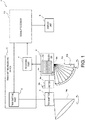
- Fig. 1 is a block diagram illustrating a configuration of the underwater detection device 1 according to the first embodiment of the present disclosure.
- the underwater detection device 1 may include a transmitter 2, a receiver 3, and a motor 4a as a rotation driving part, a rotational angle detector 4b, a transmitting/receiving device 5, a signal processor 10, and a display unit 8.
- Fig. 2 is a view schematically illustrating a transmission beam TB formed by the transmitter 2.
- the transmitter 2 may transmit a pulse-shaped ultrasonic wave underwater, and may be provided to the ship's bottom so that a transmitting surface from which the ultrasonic wave is transmitted is exposed underwater.
- the transmitter 2 may have one or more ultrasonic transducers, and may be configured to form the 3D transmission beam TB as illustrated in Fig. 2 .
- the transmitter 2 may be provided to the ship's bottom so that a center axis Ax of the transmission beam TB is obliquely oriented with respect to the vertical direction (z-axis direction in Fig. 2 ). As illustrated in Fig.
- the transmission beam TB has a certain thickness (angle ⁇ A ) when seen vertically, and has a substantially sector shape when seen in the thickness direction.
- angle ⁇ A is, for example, 30°, but it may be within a range of 6° to 90° without being limited to 30°.
- a possible angle range ⁇ 1 of the transmission beam TB of the fan shape in the vertical direction is, for example, when the vertically downward is set as 0°, an angle range from 0° (vertically downward) to 90° (horizontal).
- the angle range ⁇ 1 may be an angle range from 30° to 90° (horizontal), or may be an angle range from 45° to 90° (horizontal).
- the angle range ⁇ 1 may be an angle range from -60° to 60° which is an angle range including the vertically downward.
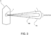
- Fig. 3 is a view of a ship S, on which the underwater detection device 1 is mounted seen from above, and is a view schematically illustrating the transmission beam TB formed by the transmitter 2 and a reception beam RB.
- the motor 4a may move the transmitter 2 and the receiver 3.
- the motor 4a may rotate the transmitter 2 and the receiver 3 centering on a center axis extending in the vertical direction, as a rotation center.
- the transmission beam TB illustrated in Fig. 3 is rotated in all the horizontal azimuth directions centering on the ship S.
- the motor 4a may continuously rotate the transmitter 2 and the receiver 3.
- the motor 4a may repeat rotation and stop of the transmitter 2 and the receiver 3 so that the transmitter 2 and the receiver 3 repeat an operation in which the transmitter 2 and the receiver 3 rotate by a given angle at a given time interval and stop for a given period of time after the rotation.
- the rotational angle detector 4b may be attached to the motor 4a.
- an encoder is used, for example.
- a signal for controlling rotation of the motor 4a may be analyzed to convert the signal into angle information.
- the number of instruction pulses inputted into the stepping motor may be counted to convert it into the angle information.
- an angular position of the transmitter 2 and the receiver 3 in the ⁇ direction may be calculated based on a rotation angle of the motor 4a detected by the rotational angle detector 4b.
- Fig. 4 is a view illustrating the transmission pulse wave transmitted from the transmitter 2.
- a first transmission pulse wave P1, a second transmission pulse wave P2, and a third transmission pulse wave P3, which are obtained by converting first to third amplified transmission pulse signals sequentially outputted from a transmitting part 6 described later in detail into the ultrasonic waves, respectively, may be transmitted.
- the transmission pulse waves P1, P2, and P3 may be comprised of pulse waves at different frequency bands.
- sequences in Fig. 4 , only three sequences Sa, Sb, and Sc are illustrated
- the first transmission pulse wave P1, the second transmission pulse wave P2, and the third transmission pulse wave P3 may repeatedly be transmitted at a constant cycle T.
- time intervals T1, T2, and T3 of the transmission pulse waves may be the same.
- the time intervals T1, T2, and T3 of the transmission pulse waves may be T/3.
- a repeating waveform which constitutes the transmission pulse waves is schematically illustrated in Fig. 4 .
- two transmission pulse waves at different frequency bands, of which the time intervals of the transmission pulses are set to be T/2 may be included in one sequence.
- four transmission pulse waves at different frequency bands, of which the time intervals of the transmission pulses are set to be T/4 may be included in one sequence.
- five or more transmission pulse waves may be included in one sequence.
- the sequence outputted first may be referred to as a first sequence
- the sequence outputted next may be referred to as a second sequence.
- Sa may be the first sequence
- Sb may be the second sequence
- Sb may be the first sequence
- Sc may be the second sequence.
- Each sequence may be transmitted at the same cycle T.
- the cycle T of the sequence may be set as a period of time between a transmission of the ultrasonic wave from the transmitter 2 and a return of the ultrasonic wave to the receiver 3 after it travels over a detection range R which is a distance at which the target object is detected by the underwater detection device 1 according to this embodiment.
- the cycle T of the sequence may be set as a time required for the ultrasonic wave to go and come back in the detection range R.
- the time intervals T1, T2, and T3 of the transmission pulse waves may be set as a shorter time interval (also referred to as a "first time interval") than the time required for the ultrasonic wave to go and come back underwater in the detection range R.
- the transmission pulse wave P1 included in the first sequence may be the first pulse wave
- the transmission pulse wave P2 included in the sequence Sa may be the second pulse wave
- the transmission pulse wave P1 included in the second sequence may be a third pulse wave
- the transmission pulse wave P2 included in the sequence Sb may be a fourth pulse wave.
- the pulse signal used as the basis of the first pulse wave may be a first pulse signal
- the pulse signal used as the basis of the second pulse wave may be a second pulse signal
- the pulse signal used as the basis of the third pulse wave may be a third pulse signal
- the pulse signal used as the basis of the fourth pulse signal may be a fourth pulse signal.
- the frequency band of the first pulse wave and the frequency band of the third pulse wave are set identically, they may be set as different frequency bands without being limited to the configuration.
- the frequency band of the second pulse wave and the frequency band of the fourth pulse wave are set identically, they may be set as different frequency bands without being limited to the configuration.
- the frequency band of the transmission pulse wave P1 included in the first sequence Sa may be a first frequency band
- the frequency band of the transmission pulse wave P2 included in the first sequence Sa may be a second frequency band
- the frequency band of the transmission pulse wave P1 included in the second sequence Sb may be a third frequency band
- the frequency band of the transmission pulse wave P2 included in the second sequence Sb may be a fourth frequency band.
- the receiver 3 may have a plurality of ultrasonic transducers 3a as wave receiving elements.
- the receiver 3 may be provided separately from the transmitter 2.
- a wave receiving surface 3b by which the ultrasonic wave is received may be exposed underwater.
- the wave receiving surface 3b provided to each ultrasonic transducer 3a may be formed in a rectangular shape, as illustrated in Fig. 1 . Note that, although the number of ultrasonic transducers 3a is eight in Fig. 1 , the number may be other number without being limited to eight. Moreover, in Fig. 1 , the shape and the orientation of each wave receiving surface 3b are illustrated schematically.
- Each ultrasonic transducer 3a may receive the reflection wave of each transmission pulse wave which is the ultrasonic wave transmitted from the transmitter 2 as a reception wave, and may convert it into an echo signal as an electrical signal.
- These ultrasonic transducers 3a may be arranged linearly. That is, the receiver 3 may be a linear array.
- An angle formed by a direction perpendicular to the wave receiving surface of the linear array, i.e., a direction in which the reception beam is formed, and a horizontal plane is, if a direction of an angle of depression is set as positive, 30°, for example. Note that this angle may be any angle, as long as it is within a range from 0° which is an angle in a case where the linear array is arranged in the vertical direction to 90° which is an angle in a case where the linear array is arranged horizontally.
- the receiver 3 may be driven and rotated by the motor 4a.
- the motor 4a may rotate the receiver 3 centering on the center axis extending in the vertical direction as a rotation center.
- the receiver 3 may rotate along the horizontal plane perpendicular to the vertical direction.
- the motor 4a may continuously rotate the receiver 3.
- the motor 4a may repeat the rotation and the stop so that the receiver 3 repeats the operation in which it rotates by the given angle at every given time interval and stops for the given period of time after the rotation.
- the motor 4a may rotate the transmitter 2 and the receiver 3 synchronizedly. That is, the transmitter 2 and the receiver 3 may not move relative to each other.
- the rotational angle detector 4b may be attached to the motor 4a.
- the angular position in the ⁇ direction of the receiver 3 may be calculated based on the rotation angle of the motor 4a detected by the rotational angle detector 4b.
- the angular position of the receiver 3 may be set as an angle of a fan area FA formed by the receiver 3 with respect to a given azimuth direction (for example, x-axis) when seen from above.
- a given azimuth direction for example, x-axis
- the fan area FA when the angular position is a first angular position ⁇ 1 is expressed by FA( ⁇ 1 )
- the fan area FA when the angular position is a second angular position ⁇ 2 is expressed by FA( ⁇ 2 ).
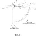
- Fig. 5 is a view schematically illustrating the fan area FA which is a range where the reception beam RB is scanned electronically.
- the receiver 3 of this embodiment may be configured to perform a beamforming together with the transmitting/receiving device 5 and the signal processor 10 which will be described in detail below, to perform the detection, by the narrow reception beam RB (refer to Fig. 1 ) which scans electronically, within the fan area FA which is the fan-shaped range where the linear array of the receiver 3 has a gain (for example, the range where ⁇ is 0° to 90°, where the vertically downward is 0°).
- This fan area FA may be formed so as to be comparatively thin, for example, with the thickness when seen in the horizontal direction being about 6°, and as illustrated in Fig.
- an angle ⁇ 2 of the fan-shaped fan area FA may be about 90°, for example.
- the fan area FA may be formed into a range from the vertically downward to the horizontal direction.
- the reception beam RB which scans electronically inside the fan area FA may be rotated in the ⁇ direction along the horizontal plane by the motor 4a.
- the reception beam RB may be rotated by the motor 4a in a direction perpendicular to a plane where the beamforming is performed (in other words, the fan area FA).
- the underwater detection device 1 can detect the target object within the 3D space covering the large area centering on the ship S, and can estimate the 3D position of the target object in the space.
- the possible angle range ⁇ 2 of the reception beam RB in the vertical direction may be an angle range from 0° to 90° (horizontal) as one example, where the vertically downward is 0°.
- the angle range may be from 30° to 90°, or may be 45° to 90°.
- the angle range may be -60° to 60° including the vertically downward.
- the transmitting/receiving device 5 may include the transmitting part 6 and a receiving part 7.
- the transmitting part 6 may amplify the transmission pulse signal generated by the signal processor 10, and apply the amplified signal to the transmitter 2 as an amplified transmission pulse signal.
- the transmission pulse waves corresponding to the respective amplified transmission pulse signals may be transmitted.
- the first transmission pulse wave corresponding to a first amplified transmission pulse signal, the second transmission pulse wave corresponding to a second amplified transmission pulse signal, and the third transmission pulse wave corresponding to a third amplified transmission pulse signal may be transmitted at a given time interval therebetween.
- the receiving part 7 may amplify the echo signal as the electrical signal outputted from the receiver 3, and A/D-convert the amplified echo signal. Then, the receiving part 7 may output the echo signal converted into the digital signal to the signal processor 10.
- the receiving part 7 may have a plurality of reception circuits, each reception circuit may perform the given processing described above to each echo signal acquired by converting the reception wave received by the corresponding ultrasonic transducer 3a into the electrical signal, and then output the echo signal to the signal processor 10.
- the signal processor 10 may generate the transmission pulse signal as the transmission signal, and then input it into the transmitting part 6. Moreover, the signal processor 10 may process the echo signal outputted from the receiving part 7, and then perform processing to generate an image data of the target object.
- the configuration of the signal processor 10 will be described later in detail.
- the display unit 8 may display an image according to the image data outputted from the signal processor 10 on the display screen.
- the display unit 8 may display an underwater state below the ship as a 3D bird's-eye view.
- a user may look at the display screen and can guess the underwater state below the ship (for example, the existence and the positions of a single fish and a school of fish, ups and downs of the seabed, and the structure such as an artificial fish reef).
- Fig. 6 is a block diagram illustrating a configuration of the signal processor 10.
- the signal processor 10 may include a controlling module 11, a transmission timing controlling module 12, a transmission signal generating module 13, a filter coefficient generating module 14, an echo signal acquiring module 15, an in-fan-area detection data generating module 20 as an image data generating module, and a 3D echo data processing module 21 as a synthesized image data generating module.
- the signal processor 10 may be comprised of devices, such as a hardware processor 9 (for example, a CPU, a FPGA, etc.) and a nonvolatile memory.
- the signal processor 10 may function as the controlling module 11, the transmission timing controlling module 12, the transmission signal generating module 13, the filter coefficient generating module 14, the echo signal acquiring module 15, the in-fan-area detection data generating module 20, and the 3D echo data processing module 21.
- the controlling module 11 may output various information to the transmission timing controlling module 12, the transmission signal generating module 13, and the filter coefficient generating module 14.
- Fig. 7(A) is a time chart of the transmission trigger outputted from the transmission timing controlling module 12
- Fig. 7(B) is a time chart of the transmission pulse wave transmitted from the transmitter
- Fig. 7(C) is a time chart of the echo signal inputted into each buffer processor 17
- Figs. 7(D) to 7(F) are time charts of extracted echo signals outputted from the buffer processor 17 to a filter processor 18, respectively.
- the controlling module 11 may notify the transmission timing controlling module 12, of timings at which the transmission timing controlling module 12 is to output the first to third transmission triggers Tr1-Tr3.
- the first transmission trigger Tr1 may be a trigger for causing the transmission signal generating module 13 to generate the first transmission pulse signal used as the basis of the first transmission pulse wave P1.
- the second transmission trigger Tr2 may be a trigger for causing the transmission signal generating module 13 to generate the second transmission pulse signal used as the basis of the second transmission pulse wave P2.
- the third transmission trigger Tr3 may be a trigger for causing the transmission signal generating module 13 to generate the third transmission pulse signal used as the basis of the third transmission pulse wave P3.
- a time interval between the first transmission trigger Tr1 and the second transmission trigger Tr2 outputted next to the first transmission trigger Tr1 may be T/3
- a time interval between the second transmission trigger Tr2 and the third transmission trigger Tr3 outputted next to the second transmission trigger Tr2 may be T/3
- a time interval between the third transmission trigger Tr3 and the first transmission trigger Tr1 outputted next to the third transmission trigger Tr3 may be T/3.
- the controlling module 11 may output information on the frequency band of the first to third transmission pulse signals to be generated by the transmission signal generating module 13 to the transmission signal generating module 13 and the filter coefficient generating module 14.
- the controlling module 11 may output a first frequency band f1, a second frequency band f2, and a third frequency band f3 which are three different frequency bands to the transmission signal generating module 13 and the filter coefficient generating module 14, as the frequency bands of the first transmission pulse signal, the second transmission pulse signal, and the third transmission pulse signal, respectively.
- the controlling module 11 may output to the filter coefficient generating module 14 filter specifications for generating a filter coefficient to be used for the filtering performed by the filter processor described later in detail (for example, a center frequency of a pass band, a bandwidth of the pass band, a reduction level of a rejecting band, a filter length, etc.).
- the transmission timing controlling module 12 may generate the first to third transmission triggers Tr1-Tr3 at the timings instructed by the controlling module 11, and then sequentially output these transmission triggers to the transmission signal generating module 13 and the echo signal acquiring module 15.
- the transmission signal generating module 13 may generate the first transmission pulse signal, the second transmission pulse signal, and the third transmission pulse signal.
- the first transmission pulse signal may be a transmission pulse signal at a frequency included in the first frequency band f1.
- the second transmission pulse signal may be a transmission pulse signal at a frequency included in the second frequency band f2.
- the third transmission pulse signal may be a transmission pulse signal at a frequency included in the third frequency band f3.
- the frequencies of the transmission pulse signals may be set as frequency bands where they are not overlapped with each other as much as possible within a frequency band range in which the ultrasonic transducers of the transmitter 2 can transmit the ultrasonic wave.
- the first to third transmission pulse signals may be generated so that the mutual time interval becomes T/3.
- each transmission pulse signal generated by the transmission signal generating module 13 may be multiplied by a given window function (for example, Gaussian window, Hamming window), and then outputted to the transmitting part 6.
- the first to third transmission pulse signals outputted to the transmitting part 6 may be amplified by the transmitting part 6, and then transmitted from the transmitter 2 as the first to third transmission pulse waves P1-P3 (refer to Fig. 7(B) ), respectively.
- the first transmission pulse wave P1, the second transmission pulse wave P2, and the third transmission pulse waves P3 may repeatedly be transmitted at the time interval of T/3. Note that, in Fig. 7(B) , the pulse signal by which the window function is not multiplied is illustrated.
- the transmission signal generating module 13 may continuously generate, with a mutual interval therebetween, a sequence comprised of the first transmission pulse signal, the second transmission pulse signal, and the third transmission pulse signal which continue in time.
- the first transmission pulse signal included in the sequence generated first may be the first pulse signal
- the second transmission pulse signal included in the sequence generated first may be the second pulse signal.
- the first transmission pulse signal included in the sequence generated thereafter may be the third pulse signal
- the second transmission pulse signal included in the sequence generated thereafter may be the fourth pulse signal. That is, the transmission signal generating module 13 may generate, in the two sequences which continue in time, the first pulse signal and the second pulse signal included in the first sequence, and the third pulse signal and the fourth pulse signal included in the next sequence.
- the filter coefficient generating module 14 may generate filter coefficients for extracting the first to third echo signals obtained from the reflection waves of the first to third transmission pulse waves P1-P3, based on the information on the first to third frequency bands notified from the controlling module 11, and the filter specification.
- the filter coefficient generating module 14 may generate a first filter coefficient ⁇ 1 for extracting the first echo signal, a second filter coefficient ⁇ 2 for extracting the second echo signal, and a third filter coefficient ⁇ 3 for extracting the third echo signal.
- the filter coefficients ⁇ 1- ⁇ 3 generated by the filter coefficient generating module 14 may be notified to the echo signal acquiring module 15.
- the filter coefficient generating module 14 may also be configured as follows.
- the filter coefficient generating module 14 may be configured to select a filter coefficient based on the number for selecting the filter specification notified from the controlling module 11, and then notify the selected filter coefficient to the echo signal acquiring module 15.
- the echo signal acquiring module 15 may acquire, from the echo signals outputted from the receiver 3 side, echo signals of the frequency bands corresponding to the respective frequency bands, in detail, a first echo signal ES1, a second echo signal ES2, and a third echo signal ES3.
- the echo signal acquiring module 15 may have the same number of echo signal extraction modules 16 as the number of ultrasonic transducers 3a provided to the receiver 3.
- the echo signal extraction modules 16 may be provided corresponding to the respective ultrasonic transducers 3a.
- Each echo signal extraction module 16 may have the buffer processor 17 and the filter processor 18.
- the buffer processor 17 While the buffer processor 17 stores the echo signals (refer to Fig. 7(C) ) sent through the corresponding channels CHm, it may output the echo signals after receiving the transmission trigger of the same kind until it again receives the transmission trigger of the same kind to the filter processor 18 as the extracted echo signals.
- the buffer processor 17 may output first extracted echo signals TES1 (refer to Fig. 7(D) ) which are echo signals after receiving the first transmission trigger Tr1 until it next receives the first transmission trigger Tr1 to the filter processor 18.
- the buffer processor 17 may output second extracted echo signals TES2 (refer to Fig. 7(E) ) which are echo signals after receiving the second transmission trigger Tr2 until it next receives the second transmission trigger Tr2 to the filter processor 18.
- the buffer processor 17 may output third extracted echo signals TES3 (refer to Fig. 7(F) ) which are echo signals after receiving the third transmission trigger Tr3 until it next receives the third transmission trigger Tr3 to the filter processor 18.
- the buffer processor 17 may output to the filter processor 18 the sequentially extracted echo signals TES1, TES2, and TES3 each time one of the first to third signals is extracted.
- Fig. 8 is a view schematically illustrating the echo signals before and after the filtering is performed by the filter processor 18.
- the filter processor 18 may extract the first to third echo signals using the respective filter coefficients ⁇ 1, ⁇ 2, and ⁇ 3 generated by the filter coefficient generating module 14.
- the filter processor 18 may extract the first echo signals ES1 by filtering the first extracted echo signals TES1 using the first filter coefficient ⁇ 1.
- the filter processor 18 may extract the second echo signals ES2 by filtering the second extracted echo signals TES2 using the second filter coefficient ⁇ 2.
- the filter processor 18 may extract the third echo signals ES3 by filtering the third extracted echo signals TES3 using the third filter coefficient ⁇ 3.
- the filter processor 18 may serve as a band pass filter.
- the filter processor 18 may have another configuration which acts similarly, instead of the band pass filter itself.
- the filter processor 18 may be comprised of a combination of a mixer and a low pass filter which convert the signal into a signal at a frequency near direct current.
- the first echo signal ES1 may include self-frequency echo signals ES1a and ES1b resulting from the first transmission pulse wave P1 transmitted in order to obtain the first echo signal ES1, and other-frequency echo signals ES1w and ES1x resulting from the transmission pulse waves P2 and P3 of other frequency bands. Since the self-frequency echo signals ES1a and ES1b are almost not influenced by the first filter coefficient ⁇ 1, its amplitude may be generally the same before and after the filtering. On the other hand, the amplitudes of the other-frequency echo signals ES1w and ES1x may reduce greatly by the filtering with the first filter coefficient ⁇ 1.
- the second echo signal ES2 may include self-frequency echo signals ES2a and ES2b resulting from the second transmission pulse wave P2 transmitted in order to obtain the second echo signal ES2, and other-frequency echo signals ES2w, ES2x, and ES2y resulting from the transmission pulse waves P1 and P3 of other frequency bands. Since the self-frequency echo signals ES2a and ES2b are almost not influenced by the second filter coefficient ⁇ 2, its amplitude may be generally the same before and after the filtering. On the other hand, the amplitudes of the other-frequency echo signals ES2w, ES2x, and ES2y may reduce greatly by the filtering with the second filter coefficient ⁇ 2.
- the third echo signal ES3 may include self-frequency echo signals ES3a and ES3b resulting from the third transmission pulse wave P3 transmitted in order to obtain the third echo signal ES3, and other-frequency echo signals ES3w, ES3x, ES3y, and ES3z resulting from the transmission pulse waves P1 and P2 of other frequency bands. Since the self-frequency echo signals ES3a and ES3b are mostly not influenced by the third filter coefficient ⁇ 3, its amplitude may be generally the same before and after the filtering. On the other hand, the amplitudes of the other-frequency echo signals ES3w, ES3x, ES3y, and ES3z may reduce greatly by the filtering with the third filter coefficient ⁇ 3.
- the in-fan-area detection data generating module 20 may perform the beamforming processing based on M echo signals acquired from the echo signal extraction modules 16.
- the beamforming techniques a case where phase regulating addition is carried out is described.
- the reception beam RB which is directed in the given direction within the range of the angle ⁇ 2 (refer to Fig. 5 ) can be formed.
- an echo intensity at each angle ⁇ can be obtained.
- the in-fan-area detection data generating module 20 can calculate the echo intensity at each position in the area specified by a distance r and the angle ⁇ with reference to the ship by obtaining the echo intensity at each angle ⁇ , for each distance r. Note that, in the following, the echo intensity may also be referred to as the "in-fan-area echo intensity.”
- the in-fan-area detection data generating module 20 may generate, at least, first image data which is the in-fan-area echo intensity (may be referred to as the "image data") when the angular position of the fan area FA is the first angular position ⁇ 1 , and second image data which is the in-fan-area echo intensity when the angular position of the fan area FA is the second angular position ⁇ 2 .
- the 3D echo data processing module 21 may synthesize the image data at every angular position ⁇ ( ⁇ 1 , ⁇ 2 , ...) which is generated by the in-fan-area detection data generating module 20 to generate synthesized image data.
- Fig. 9 illustrates an image generated based on the synthesized image data, and is a view illustrating one example of the image displayed on the display unit 8.
- an echo from a shallow position is indicated by dense hatching
- an echo from a deep position is indicated by thin hatching.
- a comparatively large echo image E considered to be originated in a school of fish at a comparatively shallow position of the port side of the ship S can be confirmed.
- the echo intensity within the fan area FA can be calculated by performing the beamforming based on the echo signals ES1, ES2, and ES3 generated based on the reception waves respectively received by the plurality of ultrasonic transducers 3a.
- the echo intensity within the 2D area can be obtained comparatively in a short period of time.
- the position of the fan beam FA formed by the receiver 3 may be changed by the motor 4a rotating the receiver 3.
- the 3D space can be detected based on the echo intensity within the fan beam area calculated at every angular position ⁇ , and the 3D position of the target object can be estimated.
- the device since it becomes unnecessary to arrange the wave receiving elements two-dimensionally or three-dimensionally like the conventionally-known scanning sonar, and the required number of wave receiving elements can be reduced, the device can be simplified.
- the second transmission pulse wave P2 in a frequency band different from that of the first transmission pulse wave P1 may be transmitted at the time interval shorter than the time T required for the ultrasonic wave to go and come back in the detection range R.
- the subsequent transmission pulse wave can be transmitted at a shorter time interval, the echo signal from the next angular direction can be acquired in a short period of time.
- the frequency band of the first transmission pulse wave is different from the frequency band of the second transmission pulse wave, it may become possible by using, for example, the filter etc., to extract the echo signal from the desired azimuth out of the echo signals having a plurality of mixed frequency bands.
- the ultrasonic detecting device which can detect the 3D position of the target object at low cost and in a comparatively short period of time, can be provided.
- the overall shape of the wave receiving surfaces 3b of the plurality of ultrasonic transducers 3a may be formed in the rectangular shape. Thus, it may become possible to scan in the fan area FA appropriately by the reception beam RB.
- the motor 4a may rotate the receiver 3 in the direction perpendicular to the fan area FA (in other words, the plane in which the beamforming is performed).
- the underwater 3D range can be detected appropriately.
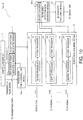
- Fig. 10 is a block diagram illustrating a configuration of a signal processor 10a of the underwater detection device according to a modification.
- the filter processor 18 tries to extract only the echo signals (for example, the self-frequency echo signals ES1a and ES1b) of the desired frequency band, some echo signals of other frequency bands (for example, the other-frequency echo signals ESlw and ES1x; hereinafter the echo signals are referred to as the "false image factor signals") remain, and therefore, a false image may be caused in the echo image by the false image factor signal.
- the false image which may appear on the display unit 8 can be reduced by performing a randomizing of the transmission cycle of the transmission pulse and a smoothing of the in-fan-area echo intensities, which will be described later in detail.
- the cycle of each of the transmission pulse waves P1-P3 may also be randomized. Therefore, referring to Fig.
- a second time interval T1b which is the time interval between the first transmission pulse wave (also referred to as the "third pulse wave”) and the second transmission pulse wave (also referred to as the "fourth pulse wave") which are included in the second sequence Sb transmitted later may become different from a first time interval T1a which is the time interval between the first transmission pulse wave P1 and the second transmission pulse wave which are included in the first sequence Sa transmitted first.
- T1a which is the time interval between the first transmission pulse wave P1 and the second transmission pulse wave which are included in the first sequence Sa transmitted first.
- an in-fan-area detection data generating module 20a of the signal processor 10a of this modification may have a smoothing module 22 as a false image reducing module which reduces the false image.
- the echo intensities at the corresponding distance r and angle ⁇ may be smoothed.
- the 3D echo data processing module 21 may output to the 3D echo data processing module 21 the in-fan-area echo intensities at every angular position ⁇ 1 , ⁇ 2 , ... to which the smoothing is performed.
- the smoothing performed by the smoothing module 22 may include an average, a weighted average, and a minimum value selection.
- the smoothing module 22 may be constituted using a FIR filter or an IIR filter.
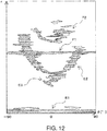
- Fig. 12 is a view illustrating one example of the in-fan-area echo intensities before performing the smoothing.
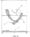
- Fig. 13 is a view illustrating one example of the in-fan-area echo intensities after performing the smoothing.
- Fig. 12 illustrates a first echo image generated based on the in-fan-area echo intensities before performing the smoothing, i.e., based on image data to which the smoothing is not performed (for example, first image data).
- the first echo image may include echo images E1, E2, and E3 obtained by the first transmission pulse waves P1 of the first frequency bands, and false images F1 and F2 obtained by the second transmission pulse waves P2 of the second frequency bands.
- the echo image E1 may be an echo image obtained by the first transmission pulse wave P1 being directly received by the receiver 3, and may be a so-called "emission line.”
- the echo image E2 may be an echo image resulting from the seabed.
- the echo image E3 may be an echo image resulting from a school of fish or a fishing reef.
- the false image F1 may be an echo image obtained by the second transmission pulse wave P2 transmitted after a given period of time of the transmission of the first transmission pulse wave being directly received by the receiver 3, and may be a false image resulting from a false image factor signal which is not able to be removed by the filter processor 18.
- the false image F2 may be an echo image resulting from the reception wave obtained from the second transmission pulse wave P2 reflecting on the seabed, and may be a false image resulting from the false image factor signal which is not able to be removed by the filter processor 18.
- the false images F1 and F2 resulting from the false image factor signals may appear in the echo image before the smoothing is performed.
- the first image data and the second image data which are obtained corresponding to the adjacent angular positions may be smoothed.
- the positions of the false images which appear in the respective image data may shift from each other in the r-direction.
- the positions of the false images included in the respective echo images can be mutually shifted in the r-direction by randomizing the timings at which the transmission pulse waves P1-P3 are transmitted within the given range.
- the false images which may be included in the synthesized image data can be reduced by the smoothing of the smoothing module 22.
- the false images which may be included in the synthesized image data can be appropriately reduced by smoothing the first image data and the second image data which are obtained corresponding to the adjacent angular positions.
- the present disclosure is not limited to this configuration.
- a plurality of in-fan-area echo intensities at substantially the same angular position obtained by rotating the receiver 3 for a plurality of times may be smoothed. Even with this configuration, the false images which may be included in the synthesized image data can be reduced appropriately.
- the plurality of in-fan-area echo intensities to be smoothed may be ideally echo intensities acquired at exactly the same angular position.
- the present disclosure is not limited to this configuration. In detail, even if there is the regularity in the transmission timings of the transmission pulse waves P1-P3, it may be desirable that the timings at which the transmission pulse waves P1-P3 are transmitted are not constant.
- the underwater detection device which is capable of performing both the randomizing of the transmission timings of the transmission pulse waves P1-P3 and the smoothing by the smoothing module 22 is described as the example, the present disclosure is not limited to this configuration.
- the smoothing module 22 may be omitted in the signal processor 10a according to the modification illustrated in Fig. 10 .
- the false image F1 illustrated in Fig. 12 is not linear but is displayed as a false image having a certain width in the r-direction, so that the false image F1 may be displayed as a whole in a blurred state.
- the user may visually recognize that the echo intensities of the false image F1 appear to be reduced.
- Fig. 14 is a block diagram illustrating a configuration of a signal processor 10b of the underwater detection device according to a modification.
- Fig. 15 is a schematic view illustrating a process in which the false image factor signal is reduced by an echo signal acquiring module 15a of the signal processor 10b illustrated in Fig. 14 .
- each echo signal extraction module 16a of the echo signal acquiring module 15a of this modification may further be provided with a false image detecting module 23 and an echo intensity reducing module 24, in addition to the buffer processor 17 and the filter processor 18.
- the false image detecting modules 23 may detect the false image factor signals included in the first to third extracted echo signals TES1, TES2, and TES3 extracted by the buffer processors 17.
- the false image factor signal included in the first extracted echo signal TES1 may be considered to include an echo signal FS2 obtained at almost the same timing as the timing at which the second transmission pulse wave P2 is transmitted (in other words, the timing at which the second transmission trigger is outputted). This may be because the second transmission pulse wave P2 transmitted from the transmitter 2 is directly received by the receiver 3, with no time interval.
- the false image factor signal included in the first extracted echo signal TES1 may be considered to include an echo signal FS3 obtained at almost the same timing as the timing at which the third transmission pulse wave P3 is transmitted (in other words, the timing at which the third transmission trigger is outputted). This may be because the third transmission pulse wave P3 transmitted from the transmitter 2 is directly received by the receiver 3, with no time interval.
- the false image detecting module 23 may detect a signal with comparatively large amplitude generated immediately after receiving the second transmission trigger Tr2, and the signal with comparatively large amplitude generated immediately after receiving the third transmission trigger Tr3 as false image factor signals FS2 and FS3.
- the echo intensity reducing module 24 may reduce the echo intensities of the false image factor signals FS2 and FS3 detected by the false image detecting module 23.
- the echo intensity reducing module 24 may output to the filter processor 18 the first extracted echo signal from which the echo intensities of the false image factor signals FS2 and FS3 are reduced in this way, as first echo signal TES1'.
- the false image factor signals resulting from the transmission pulse waves of other frequencies can be reduced. Therefore, it may be possible to make the false images which may appear in the echo images displayed on the display unit 8 inconspicuous.
- the false image detecting module 23 and the echo intensity reducing module 24 as the false image reducing module are provided before the filter processor 18, the present disclosure is not limited to this configuration.
- the false image detecting module 23 and the echo intensity reducing module 24 may be provided after the filter processor 18. That is, referring to Fig. 8 , the false image factor signals may be detected in the echo signals ES1, ES2, and ES3 after the filtering is performed, and these echo intensities may be reduced. Even in this case, the false images which may appear in the echo images displayed on the display unit 8 can be made inconspicuous.
- the false image detecting module 23 and the echo intensity reducing module 24 may be provided in the in-fan-area detection data generating module 20.
- the false image detecting module 23 may detect the false image F1 with reference to the transmission timing of each transmission trigger, for example, in each image data as illustrated in Fig. 12 .
- the echo intensity reducing module 24 may reduce the echo intensity of the false image F1 detected by the false image detecting module 23. Even in this case, the false images which may appear in the echo images displayed on the display unit 8 can be made inconspicuous.
- the underwater detection device subject to the randomizing of the transmission timings of the transmission pulse waves P1-P3 is described, it is not limited to this configuration, but may be an underwater detection device which transmits the transmission pulse waves P1-P3 at a given time interval. Even with such an underwater detection device, by the false image detecting module 23 and the echo intensity reducing module 24, the false images which may appear in the echo images displayed on the display unit 8 can be made inconspicuous.
- Figs. 16(A) and 16(B) are schematic views illustrating a transmission beam and a reception beam which are formed by an underwater detection device 1a according to a modification, together with the ship S on which the underwater detection device 1a is mounted, where Fig. 16(A) is a view seen from the side and Fig. 16(B) is a view seen from above.
- the underwater detection device 1 according to the above embodiment is configured to detect below the ship, it is not limited to this configuration, but may be configured to detect forward of the ship, like the underwater detection device 1a according to this modification. That is, the underwater detection device 1a according to this modification may be provided as a forward detection sonar which can detect a reef forward of the ship leading to stranding etc.
- the underwater detection device 1a according to this modification differs greatly in the detectable range, compared with the underwater detection device 1 according to the above embodiment, but the configuration may be about the same as that illustrated in Fig. 1 .
- the underwater detection device 1a according to this modification may be provided with the transmitter 2 having a similar configuration as the above embodiment.
- the transmitter 2 may be fixed to the front side of the ship so that the transmitting surface is inclined forward of the ship with respect to the vertical direction.
- a volume beam VB as the transmission beam may be formed underwater so as to extend forward of the ship.
- the shape of the volume beam VB may be formed in, for example, a cone which can cover, when the horizontal direction is set as 0° and the vertically downward direction is set as 90°, a range of 0° to 45° in the up-and-down direction, and can cover a range from 45° starboard side to 45° port side in the left-and-right direction.
- the underwater detection device 1a according to this modification may be provided with the receiver 3 having a similar configuration to the above embodiment, and the plurality of ultrasonic transducers 3a may be arranged in the left-and-right direction of the ship.
- the receiver 3 similar to the transmitter 2, the receiver 3 may be arranged forward of the ship so that the wave receiving surface is inclined forward of the ship with respect to the vertical direction. Therefore, in the underwater detection device 1a according to this modification, the fan area FA defined as a range where the plurality of ultrasonic transducers 3a of the receiver 3 have a gain may be formed so as to extend underwater forward of the ship.
- the shape of the fan area FA in this modification may cover, for example, a range of a comparatively thin two-dimensional shape of which the thickness in the up-and-down direction is about 6°, and from 45° starboard side to 45° port side when the forward is set as 0°.
- the echo intensities within the fan area FA can be obtained.
- the receiver 3 of this modification may be inclined by the motor 4a upwardly or downwardly so that it reciprocates in the up-and-down direction.
- the motor 4a may rotate the receiver 3 along a vertical plane.
- the detection device which can detect the 3D position of the target object at low cost and in a comparatively short period of time, can be provided.
- the detection device which can detect appropriately the detection area which extends in the given direction (for example, forward of the ship) with the comparatively simple configuration can be constituted.
- the arrangement direction of the plurality of ultrasonic transducers 3a may be a direction along a vertical plane, and the driving or rotating direction of the fan area FA may be a direction perpendicular to the arrangement direction of the plurality of ultrasonic transducers 3a.
- the arrangement direction of the plurality of ultrasonic transducers 3a and the driving direction of the fan area FA it may become possible to detect the range from the sides of the ship, or the range from the front to the sides of the ship.
- the transmitter 2 is rotated by the motor 4a, it is not limited to this configuration.
- the underwater detection device in which the motor 4a only rotates the receiver 3 and does not rotate the transmitter 2 may be constituted.
- the transmitter may be a transmitter capable of forming a transmission beam which spreads underwater toward all the azimuth directions centering on the ship S.
- the echo intensity at each angle ⁇ in the fan area FA is calculated by summing phase shifted signals as the beamforming technique of the in-fan-area detection data generating module 20, it is not limited to this configuration.
- the echo intensity at each angle ⁇ in the fan area FA may be calculated using an adaptive beamforming method, such as the Capon method and the MUSIC method.
- the receiver 3 is formed in the linear array type, it is not limited to this configuration, and, for example, by arranging the plurality of ultrasonic transducers 3a in a row along an arc, the range of the fan area FA can be expanded in the ⁇ direction, and therefore, a larger area can be detected.
- each transmission pulse wave is a single frequency, it is not limited to this configuration.
- the frequency of each transmission pulse wave may be desirably included in a given frequency band.
- each transmission pulse wave may be used as a frequency modulation pulse wave, and an underwater detection device which performs a pulse compression during a process of a reflection wave thereof may be constituted.
- the underwater detection device which excels in both the resolution in the distance direction and the Doppler tolerance can be provided.
- the transmitter 2 and the receiver 3 are rotated by a sole motor 4a, it is not limited to this configuration. In detail, the transmitter 2 and the receiver 3 may be rotated by separate motors.
- An underwater detection device 1A according to this embodiment of the present disclosure may be the underwater detection device of a so-called multi-ping type, similar to the underwater detection device 1 of the first embodiment.
- the underwater detection device 1A is, for example, a fish finder, and is mounted on the bottom of the ship S as a ship. This underwater detection device 1A may be mainly used for detecting target objects, such as a fish and a school of fish, within a given underwater detection range below the ship. The underwater detection device 1A may be used for other applications, such as a detection of ups and downs of the seabed, such as a reef, and a structure, such as an artificial fish reef.
- This underwater detection device 1A may be an ultrasonic detecting device with one channel (single beam), and it can display the target object in a 2D image of which the dimensions are comprised of a dimension of a propagating direction of the ultrasonic wave and a dimension of time, as will be described later in detail. Further, in this second embodiment, the underwater detection device 1A to which the multi-ping technique is applied may prevent a generation of the false image caused by the transmission at the plurality of frequencies by differentiating the transmission timings of the plurality of frequencies.
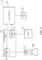
- Fig. 17 is a block diagram illustrating a configuration of the underwater detection device 1A according to the second embodiment of the present disclosure.
- the underwater detection device 1A may include a transmitter 2A, a receiver 3A, a transmitting/receiving device 5A, a signal processor 10A, and a display unit 8A.
- the transmitter 2A may transmit the pulse-shaped ultrasonic wave underwater, and it may be provided to the ship's bottom so that the transmitting surface from which the ultrasonic wave is transmitted is exposed underwater.
- the transmitter 2A may have one or more ultrasonic transducers, and may be configured to be formable of a transmission beam TBA of a pulse shape as illustrated in Fig. 17 .
- the transmitter 2A may be provided to the ship's bottom so that a center axis of the transmission beam TBA is oriented in the vertical direction.
- the transmission beam TBA may repeatedly be transmitted in connection with a traveling of the ship S moving in a direction D1, and may be sequentially transmitted toward a vertical plane perpendicular to the moving direction D1.
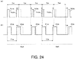
- Fig. 18 is a view illustrating a transmission pulse wave transmitted from the transmitter 2A.
- a first transmission pulse wave P1A, a second transmission pulse wave P2A, and a third transmission pulse wave P3A which are obtained by converting into ultrasonic waves the first to third amplified transmission pulse signals sequentially outputted from the transmitting part 6A, as will be described later in detail, may be transmitted.
- the transmission pulse waves P1A, P2A, and P3A may be comprised of pulse waves at different frequency bands.
- a sequence including the first transmission pulse wave P1A, the second transmission pulse wave P2A, and the third transmission pulse wave P3A as one set may repeatedly be transmitted at every fixed cycle TA.
- Fig. 18 three sequences SaA, SbA, and ScA are illustrated.
- times TA of the three sequences SaA, SbA, and ScA may be the same.
- time intervals of the transmission pulse waves in one sequence may be different.
- the time intervals T1a, T2a, and T3a of the transmission pulse waves may be T/3.
- the time interval T1b, T2b, and T3b of the transmission pulse waves may be T1b>T2b>T3b.
- the time intervals T1c, T2c, and T3c of the transmission pulse waves may be T1c ⁇ T2c ⁇ T3c.
- the three sequences SaA, SbA, and ScA may repeatedly be transmitted in this order.
- the configuration may be altered.
- two, or four or more sequences are set, and the time intervals of the transmission pulse waves P1A-P3A in each sequence may differ from each other.
- the time intervals of the transmission pulse waves P1A-P3A in one sequence may be set at random by the signal processor 10A described later.
- the configuration in which the time intervals of the transmission pulse waves P1A-P3A in one sequence are set at random will be described later as a modification.
- the transmission pulse waves P1A-P3A are schematically illustrated. Moreover, although the three transmission pulse waves P1A-P3A at mutually different frequency bands are included in one sequence, the present disclosure is not limited to this configuration. In detail, two, or four or more transmission pulse waves at different frequency bands may be included in one sequence. Also in this case, the time intervals of the transmission pulses may be set differently for every sequence.
- a sequence outputted first among the adjacent sequences in time may be referred to as a first sequence
- a sequence outputted thereafter may be referred to as a second sequence.
- SaA may be the first sequence
- SbA may be the second sequence
- SbA may be the first sequence
- ScA may be the second sequence.
- each sequence SaA, SbA, and ScA may be transmitted at the same cycle TA.
- the cycle TA of the sequence may be set as a period of time between a transmission of the ultrasonic wave from the transmitter 2A and a retuning of the ultrasonic wave to the receiver 3A after the ultrasonic wave travels over the detection range R which is the distance within which the target object is detected by the underwater detection device 1A according to this embodiment.
- the cycle TA of the sequence may be set as a time required for the ultrasonic wave to go and come back in the detection range R.
- the time intervals T1a, T1b, T1c, T2a, T2b, T2c, T3a, T3b, and T3c of the transmission pulse waves adjacent to each other in time may be all set as time intervals shorter than the time required for the ultrasonic wave to go and come back underwater in the detection range R (may be referred to as a "first time interval” and a "second time interval").
- the transmission pulse wave P1A included in the first sequence may be the first pulse wave
- the transmission pulse wave P2A included in the sequence SaA may be the second pulse wave
- the transmission pulse wave P1A included in the second sequence (for example, the sequence SbA) may be the third pulse wave
- the transmission pulse wave P2A included in the sequence SbA may be the fourth pulse wave.
- the pulse signal used as the basis of the first pulse wave may be the first pulse signal
- the pulse signal used as the basis of the second pulse wave may be the second pulse signal
- the pulse signal used as the basis of the third pulse wave may be the third pulse signal
- the pulse signal used as the basis of the fourth pulse wave may be the fourth pulse signal, which are described above.
- the frequency band of the first pulse wave and the frequency band of the third pulse wave are set identically, they may be set as different frequency bands without being limited to the configuration.
- the frequency band of the second pulse wave and the frequency band of the fourth pulse wave are set identically, they may be set as different frequency bands without being limited to the configuration.
- the frequency band of the transmission pulse wave P1A included in the first sequence SaA may be the first frequency band
- the frequency band of the transmission pulse wave P2A included in the first sequence SaA may be the second frequency band
- the frequency band of the transmission pulse wave P1A included in the second sequence SbA may be the third frequency band
- the frequency band of the transmission pulse wave P2A included in the second sequence SbA may be the fourth frequency band.
- the receiver 3A may have one ultrasonic transducer.
- the receiver 3A may be provided separately from the transmitter 2A.
- the ultrasonic transducer of the receiver 3A may have the wave receiving surface by which the ultrasonic wave is received, and this wave receiving surface may be exposed underwater.
- the ultrasonic transducer of the receiver 3A may receive the reflection wave of each transmission pulse wave which is the ultrasonic wave transmitted from the transmitter 2A as the reception wave, and convert it into the echo signal as the electrical signal.
- the transmitting/receiving device 5A may include a transmitting part 6A and a receiving part 7A.
- the transmitting part 6A may amplify the transmission pulse signal generated by the signal processor 10A, and apply the amplified signal to the transmitter 2A as the amplified transmission pulse signal.
- the transmission pulse waves P1A-P3A corresponding to the amplified transmission pulse signals may be transmitted.
- the first transmission pulse wave P1A corresponding to the first amplified transmission pulse signal, the second transmission pulse wave P2A corresponding to the second amplified transmission pulse signal, and the third transmission pulse wave P3A corresponding to the third amplified transmission pulse signal may be transmitted with a given time interval therebetween.
- the receiving part 7A may amplify the echo signal as the electrical signal outputted from the receiver 3A, and then A/D-convert the amplified echo signal. Then, the receiving part 7A may output the echo signal converted into the digital signal to the signal processor 10A.
- the receiving part 7A may have the reception circuit. This reception circuit may perform a given processing described above to each echo signal acquired by converting the reception wave received by the ultrasonic transducer of the receiver 3A into the electrical signal, and then output each echo signal to the signal processor 10A.
- the signal processor 10A may generate the transmission pulse signal as the transmission signal, and input it into the transmitting part 6A. Moreover, the signal processor 10A may process the echo signal outputted from the receiving part 7A, and perform a processing to generate the image data of the target object. The configuration of the signal processor 10A will be described later in detail.
- the display unit 8A may display the image according to the image data outputted from the signal processor 10A on the display screen.
- the display unit 8A may display the underwater state below the ship as the 2D image of which the dimensions are comprised of the dimension of the propagating direction of the ultrasonic wave and the dimension of time.
- the user may look at the display screen and can guess the underwater state below the ship (for example, the existence and the positions of a single fish and a school of fish, ups and downs of the seabed, and the structure such as an artificial fish reef).
- Fig. 19 is a block diagram illustrating a configuration of the signal processor 10A.
- the signal processor 10A may have a controlling module 11A, a transmission timing controlling module 12A, a transmission signal generating module 13A, a filter coefficient generating module 14A, an echo signal acquiring module 15A, and an image data generating module 20A.
- the signal processor 10A may be comprised of devices, such as a hardware processor 9A (for example, a CPU, a FPGA, etc.) and a nonvolatile memory.
- the signal processor 10A may function as the controlling module 11A, the transmission timing controlling module 12A, the transmission signal generating module 13A, the filter coefficient generating module 14A, the echo signal acquiring module 15A, and the image data generating module 20A.
- the controlling module 11A may output various information to the transmission timing controlling module 12A, the transmission signal generating module 13A, and the filter coefficient generating module 14A.
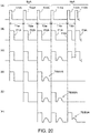
- Fig. 20(A) is a time chart of transmission triggers outputted from the transmission timing controlling module 12A
- Fig. 20(B) is a time chart of the transmission pulse waves transmitted from the transmitter
- Fig. 20(C) is a time chart of the echo signal inputted into the buffer processor 17A
- Figs. 20(D) to 20(F) are time charts of extracted echo signals outputted to a filter processor 18A from a buffer processor 17A.
- the controlling module 11A may notify the timings at which the transmission timing controlling module 12A is to output first to third transmission triggers Tr1A-Tr3A to the transmission timing controlling module 12A.
- the first transmission trigger Tr1A may be a trigger for causing the transmission signal generating module 13A to generate the first transmission pulse signal used as the basis of the first transmission pulse wave P1A.
- the second transmission trigger Tr2A may be a trigger for causing the transmission signal generating module 13A to generate the second transmission pulse signal used as the basis of the second transmission pulse wave P2A.
- the third transmission trigger Tr3A may be a trigger for causing the transmission signal generating module 13A to generate the third transmission pulse signal used as the basis of the third transmission pulse wave P3A.
- the time intervals equivalent to the time intervals between the transmission pulse waves P1A-P3A in the sequence SaA are set. That is, the time interval between the first transmission trigger Tr1A and the second transmission trigger Tr2A outputted next to the first transmission trigger Tr1A may be T1a, the time interval between the second transmission trigger Tr2A and the third transmission trigger Tr3A outputted next to the second transmission trigger Tr2A may be T2a, and the time interval between the third transmission trigger Tr3A and the first transmission trigger Tr1A outputted next to the third transmission trigger Tr3A may be T3a.
- the time intervals equivalent to the time intervals between the transmission pulse waves in the sequence SbA may be set. That is, the time interval between the first transmission trigger Tr1A and the second transmission trigger Tr2A outputted next to the first transmission trigger Tr1A may be T1b, the time interval between the second transmission trigger Tr2A and the third transmission trigger Tr3A outputted next to the second transmission trigger Tr2A may be T2b, and the time interval between the third transmission trigger Tr3A and the first transmission trigger Tr1A outputted next to the third transmission trigger Tr3A may be T3b.
- the time intervals equivalent to the time intervals between the transmission pulse waves in the sequence ScA may be set. That is, the time interval between the first transmission trigger Tr1A and the second transmission trigger Tr2A outputted next to the first transmission trigger Tr1A may be T1c, the time interval between the second transmission trigger Tr2A and the third transmission trigger Tr3A outputted next to the second transmission trigger Tr2A may be T2c, and the time interval between the third transmission trigger Tr3A and the first transmission trigger Tr1A outputted next to the third transmission trigger Tr3A may be T3c.
- the controlling module 11A may output information on the frequency bands of the first to third transmission pulse signals to be generated by the transmission signal generating module 13A, to the transmission signal generating module 13A and the filter coefficient generating module 14A.
- the controlling module 11A may output a first frequency band f1A, a second frequency band f2A, and a third frequency band f3A which are three different frequency bands to the transmission signal generating module 13A and the filter coefficient generating module 14A as the respective frequency bands of the first transmission pulse signal, the second transmission pulse signal, and the third transmission pulse signal.
- controlling module 11A may output the filter specification for generating the filter coefficient to be used by the filtering performed by the filter processor described later in detail (for example, the center frequency of the pass band, the bandwidth of the pass band, the reduction level of the rejecting band, the filter length, etc.) to the filter coefficient generating module 14A.
- the transmission timing controlling module 12A may generate the first to third transmission triggers Tr1A-Tr3A at the timings instructed by the controlling module 11A, and sequentially output the transmission triggers to the transmission signal generating module 13A and the echo signal acquiring module 15A.
- the transmission signal generating module 13A may generate the first transmission pulse signal, the second transmission pulse signal, and the third transmission pulse signal.
- the first transmission pulse signal may be a transmission pulse signal at a frequency included in first frequency band f1A.
- the second transmission pulse signal may be a transmission pulse signal at a frequency included in second frequency band f2A.
- the third transmission pulse signal may be a transmission pulse signal at a frequency included in third frequency band f3A.
- the frequencies of the transmission pulse signals may be set within frequency bands which are not overlapped with each other as much as possible within a frequency band range in which the ultrasonic transducer of the transmitter 2A can transmit the ultrasonic wave.
- the transmission signal generating module 13A may generate the first transmission pulse signal, the second transmission pulse signal, and the third transmission pulse signal in this order, each time it receives the transmission triggers Tr1A-Tr3A, respectively.
- the first to third transmission pulse signals may be generated so that the mutual time intervals become T1a, T2a, and T3a.
- the first to third transmission pulse signals may be generated so that the mutual time intervals become T1b, T2b, and T3b.
- the first to third transmission pulse signals may be generated so that the mutual time intervals become T1c, T2c, and T3c.
- each transmission pulse signal generated by the transmission signal generating module 13A may then be outputted to the transmitting part 6A.
- a given window function for example, a Gaussian window, a Hamming window
- the first to third transmission pulse signals outputted to the transmitting part 6A may be then transmitted underwater from the transmitter 2A as the first to third transmission pulse waves P1A-P3A, respectively (refer to Fig. 20(B) ).
- the first transmission pulse wave P1A, the second transmission pulse wave P2A, and the third transmission pulse wave P3A may repeatedly be transmitted at the time intervals Ta (T1a, T2a, T3a), Tb (T1b, T2b, T3b), and Tc (T1c, T2c, T3c), respectively.
- Ta T1a, T2a, T3a
- Tb T1b, T2b, T3b
- Tc T1c, T2c, T3c
- the transmission signal generating module 13A may continuously generate the sequence SaA, SbA, and ScA comprised of the first transmission pulse signal, the second transmission pulse signal, and the third transmission pulse signal which are continuous in time with intervals therebetween.
- the first transmission pulse signal included in the sequence generated first may be the first pulse signal
- the second transmission pulse signal included in the sequence generated first may be the second pulse signal.
- the first transmission pulse signal included in the sequence generated thereafter may be the third pulse signal
- the second transmission pulse signal included in the sequence generated thereafter may be the fourth pulse signal. That is, the transmission signal generating module 13A may generate, in two consecutive sequences in time, the first pulse signal and the second pulse signal included in the first sequence, and the third pulse signal and the fourth pulse signal included in the next sequence.
- the filter coefficient generating module 14A may generate the filter coefficients for extracting the first to third echo signals obtained from the respective reflection waves of the first to third transmission pulse waves P1A-P3A based on the information on the first to third frequency bands notified from the controlling module 11A, and the filter specification.
- the filter coefficient generating module 14A may generate a first filter coefficient ⁇ 1A for extracting the first echo signal, a second filter coefficient ⁇ 12A for extracting the second echo signal, and a third filter coefficient ⁇ 3A for extracting the third echo signal.
- the filter coefficients ⁇ 1A- ⁇ 3A generated by the filter coefficient generating module 14A may be notified to the echo signal acquiring module 15A.
- the filter coefficient generating module 14A may be constituted as follows.
- the filter coefficient generating module 14A may be configured to select a filter coefficient based on the number for selecting the filter specification notified from the controlling module 11A, and notifying the selected filter coefficient to the echo signal acquiring module 15A.
- Fig. 21 is a view schematically illustrating echo signals before and after the filtering is performed by the filter processor 18A.
- the echo signal acquiring module 15A may acquire the echo signals of the frequency bands corresponding to the respective frequency bands, i.e., a first echo signal ES1A, a second echo signal ES2A, and a third echo signal ES3A, from the echo signals outputted from the receiver 3A side.
- the echo signal acquiring module 15A may have a single echo signal extraction module 16A.
- the echo signal extraction module 16A may be provided corresponding to the single ultrasonic transducer of the receiver 3A.
- the echo signal extraction module 16A may have the buffer processor 17A and the filter processor 18A.
- the buffer processor 17A may store the echo signals (refer to Fig. 20(C) ) sent from the receiver 3A, and output the echo signals after receiving the transmission trigger of the same kind until it receives the next transmission trigger of the same kind, to the filter processor 18A as the extracted echo signals.
- the buffer processor 17A may output a first extracted echo signal TES1A which is an echo signal after receiving the first transmission trigger Tr1A until it next receives the first transmission trigger Tr1A to the filter processor 18A.
- the buffer processor 17A may output a second extracted echo signal TES2A which is an echo signal after receiving the second transmission trigger Tr2A until it next receives the second transmission trigger Tr2A to the filter processor 18A.
- the buffer processor 17A may output a third extracted echo signal TES3A which is an echo signal after receiving the third transmission trigger Tr3A until it next receives the third transmission trigger Tr3A to the filter processor 18A.
- the buffer processor 17A may output each of the extracted echo signals TES1A, TES2A, and TES3A which are extracted sequentially, to the filter processor 18A.
- the filter processor 18A may extract the first to third echo signals using the respective filter coefficients ⁇ 1A, ⁇ 2A, and ⁇ 3A generated by the filter coefficient generating module 14A.
- the filter processor 18A may extract a first echo signal ES1A by filtering the first extracted echo signal TES1A using the first filter coefficient ⁇ 1A.
- the filter processor 18A may extract a second echo signal ES2A by filtering the second extracted echo signal TES2A using the second filter coefficient ⁇ 2A.
- the filter processor 18A may extract a third echo signal ES3A by filtering the third extracted echo signal TES3A using the third filter coefficient ⁇ 3A.
- the filter processor 18A may serve as a band pass filter.
- the filter processor 18A may not be the band pass filter itself, but may have another configuration which acts similarly.
- the filter processor 18A may be constituted by combining the mixer and the low pass filter which convert a signal into a signal at a frequency near a direct current.
- the first echo signal ES1A may include self-frequency echo signals ESlaA and ES1bA resulting from the first transmission pulse wave P1A transmitted in order to obtain the first echo signal ES1A, and other-frequency echo signals ES1wA and ES1xA resulting from the transmission pulse waves P2A and P3A of other frequency bands. Since the self-frequency echo signals ES1aA and ES1bA are almost not influenced by the first filter coefficient ⁇ 1A, their amplitudes may be generally the same before and after the filtering. On the other hand, the other-frequency echo signals ES1wA and ES1xA may reduce their amplitudes greatly by the filtering using the first filter coefficient ⁇ 1A.
- the second echo signal ES2A may include self-frequency echo signals ES2aA and ES2bA resulting from the second transmission pulse wave P2A transmitted in order to obtain the second echo signal ES2A, and other-frequency echo signals ES2wA, ES2xA, and ES2yA resulting from the transmission pulse waves P1A and P3A of other frequency bands. Since the self-frequency echo signals ES2aA and ES2bA are almost not influenced by the second filter coefficient ⁇ 2A, their amplitudes may be generally the same before and after the filtering. On the other hand, the other-frequency echo signals ES2wA, ES2xA, and ES2yA may reduce their amplitudes greatly by the filtering using the second filter coefficient ⁇ 2A.
- the third echo signal ES3A may include self-frequency echo signals ES3aA and ES3bA resulting from the third transmission pulse wave P3A transmitted in order to obtain the third echo signal ES3A, and other-frequency echo signals ES3wA, ES3xA, ES3yA, and ES3zA resulting from the transmission pulse waves P1A and P2A of other frequency bands. Since the self-frequency echo signals ES3aA and ES3bA are almost not influenced by the third filter coefficient ⁇ 3A, their amplitudes may be generally the same before and after the filtering. On the other hand, the other-frequency echo signals ES3wA, ES3xA, ES3yA, and ES3zA may reduce their amplitudes greatly by the filtering using the third filter coefficient ⁇ 3A.
- the image data generating module 20A may generate the image data of the detection image based on signal levels of the echo signals according to the depth at each position in the moving direction D1, obtained from the echo signal extraction module 16A.
- Fig. 22(A) illustrates an image generated based on the image data generating module 20A, and is a view illustrating one example of the image displayed on the display unit 8A.
- Fig. 22(B) is an image generated based on the image data generating module 20A when the transmission interval of the transmission pulse wave is a single kind, and is a view illustrating a comparative example of the image displayed on the display unit 8A.
- the left-and-right direction of the image is the moving direction D1 of the ship S
- the up-and-down direction is a depth direction D2 (the vertical direction).
- a seabed image is not displayed on the display unit 8A, and a situation where images to be displayed on the display unit 8A are only an emission line image TL and a school-of-fish image TG is described.
- Figs. 22(A) and 22(B) as one example, a state where the emission line image TL and the school-of-fish image TG are drawn in the detection image, and emission line false images L and school-of-fish false images F are displayed around the school-of-fish image TG.
- the echo images adjacent to each other in the moving direction D1 are actually displayed without being discrete in the moving direction D1. However, in this embodiment, giving priority to visual clarity, the echo images adjacent to each other in the moving direction D1 are partially displayed so as to be dispersed in the moving direction D1.
- the time intervals between the transmission pulses P1A-P3A may be mutually differentiated in the sequences SaA, SbA, and ScA.
- the emission line false images L are displayed in zigzag in the moving direction D1.
- the school-of-fish false images F are also displayed in zigzag in the moving direction D1.
- the areas indicative of the school-of-fish false images F may be enclosed with two-dot chain lines which are imaginary lines.
- the school-of-fish image TG may be an image which is continuous in the moving direction D1.
- the images may be shifted in the depth direction D2, and their shapes may be displayed so that the positions in the depth direction D2 are in disorder in the moving direction D1.
- it may become easier to discriminate the emission line false images L and the school-of-fish false images F which are the false images from the school-of-fish image TG.
- the emission line false images L and the school-of-fish false images F resulting from the other-frequency echo signals may appear at different positions for the echo intensity of the area obtained corresponding to each of the adjacent positions in the moving direction.
- portions of the emission line false images L and the school-of-fish false images F which result from each sequence may be displayed so as to be enlarged so that each portion has the shape united in a bundle in the moving direction D1. This may make difficult to identify the school-of-fish false images F and the school-of-fish image TG.
- the second transmission pulse wave P2A of which the frequency band is different from the first transmission pulse wave P1A may be transmitted at the time interval shorter than the time T required for the ultrasonic wave to go and come back in the detection range R.
- the subsequent transmission pulse wave can be transmitted at a shorter time interval, the subsequent echo signal can be acquired in a shorter period of time.
- the frequency band of the first transmission pulse wave P1A is different from the frequency band of the second transmission pulse wave P2A, it may become possible, for example by using the filter etc., to extract the echo signal of the desired frequency band out of the echo signals in which a plurality of frequency bands are mixed.
- the time intervals between the transmission pulse waves P1A-P3A in one sequence may differ from each other.
- the school-of-fish false images F may present the discontinuous shapes in the moving direction D1.
- the false image suppressing effect in which the school-of-fish false images F and the school-of-fish image TG may become easier to be identified can be acquired.
- Fig. 23 is a block diagram illustrating a configuration of the signal processor 10A according to a first modification of the second embodiment.
- the filter processor 18A tries to extract only the echo signals of desired frequency bands (for example, the self-frequency echo signals ES1aA, ES1bA), the echo signals of other frequency bands (for example, the other-frequency echo signals ES1wA and ES1xA; hereinafter, the echo signals are referred to as the "false image factor signals") may remain a little, and therefore, the emission line false images L and the school-of-fish false images F may occur in the echo image due to the false image factor signals.
- desired frequency bands for example, the self-frequency echo signals ES1aA, ES1bA
- the echo signals of other frequency bands for example, the other-frequency echo signals ES1wA and ES1xA; hereinafter, the echo signals are referred to as the "false image factor signals”
- the emission line false images L and the school-of-fish false images F may occur in the echo image due to the false image factor signals.
- the emission line false images L and the school-of-fish false images F which may appear on the display unit 8A can be reduced by performing randomizing of the transmission cycle of the transmission pulse and smoothing of the echo intensities, as will be described later in detail.
- the cycles of the transmission pulse waves P1A-P3A may be also randomized.
- the second time interval T1b which is the time interval between the first transmission pulse wave (referred to as the "third pulse wave”) and the second transmission pulse wave (referred to as the "fourth pulse wave") which are included in the second sequence SbA transmitted later may differ from first time interval T1a which is the time interval between the first transmission pulse wave P1A and the second transmission pulse wave which are included in the first sequence SaA transmitted first.
- the image data generating module 20A of the signal processor 10A of this modification may have a smoothing module 22A as the false image reducing module for reducing the false images.
- the image data generating module 20A may first read the signal level of the echo signal according to the depth (the depth direction D2) at each position in the moving direction D1, obtained from the echo signal extraction module 16A. Then, the smoothing module 22A may smooth the echo intensities obtained corresponding to the adjacent positions in the moving direction D1. In detail, as one example, as for the echo intensities obtained corresponding to the adjacent positions in the moving direction D1, corresponding echo intensities in the depth direction D2 are smoothed.
- the image data generating module 20A may generate an image data of the detection image by using the echo intensity for every moving direction position for which the smoothing is performed.
- the smoothing performed by the smoothing module 22A may include the average, the weighted average, and the minimum value selection.
- the smoothing module 22A may be constituted using the FIR filter or the IIR filter.
- Fig. 25(A) is a view illustrating one example of the detection image before performing the randomizing and the smoothing.
- Fig. 25(B) is a view illustrating one example of the detection image after performing the randomizing and the smoothing.
- Fig. 25(A) illustrates the first echo image generated based on the image data before the randomizing and the smoothing are performed (for example, the first image data).
- the school-of-fish false images F may be displayed so as to be enlarged so that the portion resulting from each sequence becomes the shape continuous in the moving direction D1 (in time series).
- D1 in time series
- the first image data and the second image data obtained corresponding to the adjacent positions in the traveling direction may be smoothed.
- the intervals of the transmission pulse waves which are adjacent to each other in time may be randomized. For this reason, the portions resulting from the transmission pulse waves adjacent to each other in time, of the emission line false images L and the school-of-fish false images F which appear in each image data may shift from each other in the depth direction D2.
- the echo intensities of the emission line false images L and the school-of-fish false images F can be reduced, while maintaining the echo intensity of the desired school-of-fish image TG.
- thin contour lines of the images express that the densities of the emission line false images L and the school-of-fish false images F may be lower than the densities of the emission line TL and the school-of-fish image TG.
- the positions of the emission line false images L and the school-of-fish false images F included in each echo image can be mutually shifted in the depth direction D2. By doing so, it may become possible to further reduce the emission line false images L and the school-of-fish false images F included in the synthesized image data, for example, by smoothing as described above in this modification.
- the densities of the emission line false images L and the school-of-fish false images F which may be included in the synthesized image data can be reduced by smoothing of the smoothing module 22A.
- the emission line false images L and the school-of-fish false images F which may be included in the synthesized image data can be appropriately reduced.
- the present disclosure is not limited to this configuration.
- the number of echo intensities smoothed at the moving direction positions may be three or more.
- each of the timings at which the transmission pulse waves P1A-P3A are transmitted is desirably not to be constant.
- the underwater detection device which can perform both the randomizing of the transmission timings of the transmission pulse waves P1A-P3A and the smoothing by the smoothing module 22A is described, the present disclosure is not limited to this configuration.
- the smoothing module 22A may be omitted.
- the effects of the false image reduction by the smoothing of echo intensities are not acquired, for example, the emission line false images L and the school-of-fish false images F illustrated in Fig. 25(B) are displayed in a generally blurred state.
- the user may observe the reduced echo intensities of the emission line false images L and the school-of-fish false images F.
- Fig. 26 is a block diagram illustrating a configuration of the signal processor 10A of the underwater detection device according to a second modification of the second embodiment.
- Fig. 27 is a schematic view illustrating a process of reducing the false image factor signals by the echo signal acquiring module 15A of the signal processor 10A according to the second modification of the second embodiment illustrated in Fig. 26 .
- each echo signal extraction module 16A of the echo signal acquiring module 15A of this modification may further include, in addition to the buffer processor 17A and the filter processor 18A, a false image detecting module 23A and an echo intensity reducing module 24A.
- the false image detecting module 23A may detect the false image factor signals included in the first to third extracted echo signals TES1A, TES2A, and TES3A ( Fig. 21 ) extracted by the buffer processor 17A.
- the first extracted echo signal TES1A is described as one example, it may be considered that the false image factor signals included in the first extracted echo signal TES1A include the echo signal FS2A obtained at almost the same timing as the timing at which the second transmission pulse wave P2A is transmitted (in other words, the timing at which the second transmission trigger is outputted). This may be because the second transmission pulse wave P2A transmitted from the transmitter 2A is directly received by the receiver 3A, with no time interval.
- the false image factor signals included in the first extracted echo signal TES1A include the echo signal FS3A obtained at almost the same timing as the timing at which the third transmission pulse wave P3A is transmitted (in other words, the timing at which the third transmission trigger is outputted). This may be because the third transmission pulse wave P3A transmitted from the transmitter 2A is directly received by the receiver 3A, with no time interval.
- the false image detecting module 23A may be notified of the transmission timing of the second transmission trigger Tr2A and the transmission timing of the third transmission trigger Tr3A from the transmission timing controlling module 12A.
- the false image detecting module 23A may detect the signal with a comparatively large amplitude generated immediately after receiving the second transmission trigger Tr2A, and the signal with a comparatively large amplitude generated immediately after receiving the third transmission trigger Tr3A as the false image factor signals FS2A and FS3A.
- the echo intensity reducing module 24A may reduce the echo intensities of the false image factor signals FS2A and FS3A detected by the false image detecting module 23A.
- the method of reducing the echo intensities of the false image factor signals FS2A and FS3A may include a method of replacing the echo intensities (amplitudes) of the false image factor signals FS2A and FS3A by another value, such as zero or a small value, and a method of replacing the echo intensities (amplitudes) by interpolated values calculated based on the received echo signals adjacent to each other in time.
- the echo intensity reducing module 24A may output the first extracted echo signal of which the echo intensities of the false image factor signals FS2A and FS3A are replaced, for example, by zero, according to such processing, to the filter processor 18A, as first echo signal TES1'A.
- the false image factor signals resulting from the first transmission pulse wave and the third transmission pulse wave may be replaced similarly to the method described for the first extracted echo signal TES1A.
- the false image factor signals resulting from the first transmission pulse wave and the second transmission pulse wave may be replaced similarly to the method described for the first extracted echo signal TES1A.
- the false image factor signals resulting from the transmission pulse waves of other frequencies can be reduced. Therefore, the false images which may appear in the echo image displayed on the display unit 8A can be made inconspicuous.
- the false image detecting module 23A and the echo intensity reducing module 24A as the false image reducing module are provided before the filter processor 18A, the present disclosure is not limited to this configuration.
- the false image detecting module 23A and the echo intensity reducing module 24A may be provided after the filter processor 18A. That is, referring to Fig. 21 , the false image factor signals may be detected in the filtered echo signals ES1A, ES2A, and ES3A, and these echo intensities may be reduced. Even in this case, the false images which may appear in the echo image displayed on the display unit 8A can be made inconspicuous.
- the false image detecting module 23A and the echo intensity reducing module 24A may be provided to the image data generating module 20A.
- the false image detecting module 23A may detect the emission line false images L and the school-of-fish false images F while referring to the transmission timings of the respective transmission triggers, for example, in each image data illustrated in Fig. 25(B) .
- the echo intensity reducing module 24A may reduce the echo intensities of the emission line false images L and the school-of-fish false images F detected by the false image detecting module 23A. Even in this case, the false images which may appear in the echo image displayed on the display unit 8A can be made inconspicuous.
- the transmission timings of the plurality of the transmission pulse waves in one sequence may be differentiated between the sequences (SaA, SbA, and ScA).
- the transmission timings of the plurality of transmission pulse waves in one sequence may be randomized between the sequences (SaA, SbA, and ScA), and (b) the echo signal levels of the receiving pulse waves which are adjacent to each other in time may be smoothed.
- the amplitude values of the echo signals leading to false image factor signals FS2A and FS3A may be replaced by other values.
- the configuration of (a1) in which the transmission timings of the transmission pulses are differentiated, and the configuration of (b) in which the echo signal levels of the receiving pulse waves which are adjacent to each other in time are smoothed may be combined.
- the configuration of the signal processor 10A when all the three configurations of the above (a) to (c) are adopted may be realized by the configuration illustrated in Fig. 26 .
- configurations of the second embodiment and its modification may be applied to the underwater detection device with a plurality CHs of two or more CHs, without being limited to the underwater detection device of 1CH.
- the configurations of the second embodiment and its modification may be applied to a side-scanning sonar provided with 2CHs comprised of a starboard-side detection beam and a port-side detection beam of the ship S.
- the configurations of the second embodiment and its modification may be configured to detect any one of the forward, the starboard side, and the port side of the ship S.
- the transmitter 2A and the receiver 3A are provided separately, it is not limited to this configuration.
- the transmitter 2A and the receiver 3A may be comprised of a single ultrasonic transducer. For example, even if the emission lines as transmission pulse wave lines of different frequencies are saturated, the echo signal values indicative of the emission lines are replaced by other values to avoid the influence of the saturation.
Landscapes
- Engineering & Computer Science (AREA)
- Radar, Positioning & Navigation (AREA)
- Remote Sensing (AREA)
- Physics & Mathematics (AREA)
- Computer Networks & Wireless Communication (AREA)
- General Physics & Mathematics (AREA)
- Acoustics & Sound (AREA)
- Measurement Of Velocity Or Position Using Acoustic Or Ultrasonic Waves (AREA)
Applications Claiming Priority (3)
| Application Number | Priority Date | Filing Date | Title |
|---|---|---|---|
| JP2017046144 | 2017-03-10 | ||
| JP2017239291 | 2017-12-14 | ||
| PCT/JP2018/006434 WO2018163844A1 (ja) | 2017-03-10 | 2018-02-22 | 超音波探知装置及び超音波探知方法 |
Publications (2)
| Publication Number | Publication Date |
|---|---|
| EP3594718A1 true EP3594718A1 (de) | 2020-01-15 |
| EP3594718A4 EP3594718A4 (de) | 2021-01-06 |
Family
ID=63448187
Family Applications (1)
| Application Number | Title | Priority Date | Filing Date |
|---|---|---|---|
| EP18764593.2A Withdrawn EP3594718A4 (de) | 2017-03-10 | 2018-02-22 | Ultraschalldetektionsvorrichtung und ultraschalldetektionsverfahren |
Country Status (4)
| Country | Link |
|---|---|
| US (1) | US11320534B2 (de) |
| EP (1) | EP3594718A4 (de) |
| JP (1) | JP6761893B2 (de) |
| WO (1) | WO2018163844A1 (de) |
Cited By (2)
| Publication number | Priority date | Publication date | Assignee | Title |
|---|---|---|---|---|
| CN111157999A (zh) * | 2020-03-23 | 2020-05-15 | 陈武强 | 一种超声波侦测系统、侦测方法以及设备 |
| RU2851246C1 (ru) * | 2024-12-16 | 2025-11-21 | Федеральное государственное казенное военное образовательное учреждение высшего образования "Военный учебно-научный центр Военно-Морского Флота "Военно-морская академия имени Адмирала флота Советского Союза Н.Г. Кузнецова" | Гидролокатор обнаружения подводных и надводных целей с адаптивной обработкой информации |
Families Citing this family (10)
| Publication number | Priority date | Publication date | Assignee | Title |
|---|---|---|---|---|
| US11320534B2 (en) | 2017-03-10 | 2022-05-03 | Furuno Electric Company Limited | Ultrasonic detecting device and ultrasonic detecting method |
| JP7119927B2 (ja) * | 2018-11-09 | 2022-08-17 | 株式会社Soken | 物体検知装置 |
| JP7243171B2 (ja) * | 2018-12-18 | 2023-03-22 | 株式会社Soken | 物体検知装置 |
| JP7257271B2 (ja) | 2019-06-19 | 2023-04-13 | 古野電気株式会社 | 水中探知装置および水中探知方法 |
| JPWO2021010082A1 (de) * | 2019-07-16 | 2021-01-21 | ||
| JP7373189B2 (ja) * | 2019-11-28 | 2023-11-02 | 本多電子株式会社 | 超音波探知装置 |
| CN111239748B (zh) * | 2020-03-16 | 2021-07-13 | 中国水产科学研究院渔业机械仪器研究所 | 一种提高水平探鱼仪航向分辨率的方法及其装置 |
| CN114814800B (zh) * | 2021-01-19 | 2025-05-27 | 腾讯科技(深圳)有限公司 | 基于超声回波的对象识别方法、装置及存储介质 |
| JP2023178121A (ja) | 2022-06-03 | 2023-12-14 | 古野電気株式会社 | 水中探知装置および水中探知方法 |
| US20240385318A1 (en) * | 2023-05-19 | 2024-11-21 | Robert Bosch Gmbh | Machine-learning based object detection and localization using ultrasonic sensor data |
Family Cites Families (37)
| Publication number | Priority date | Publication date | Assignee | Title |
|---|---|---|---|---|
| US2871459A (en) | 1946-05-06 | 1959-01-27 | Gen Electric | Submerged object locating |
| US3723955A (en) | 1965-11-15 | 1973-03-27 | Control Data Corp | Beam former |
| US4119940A (en) | 1976-10-18 | 1978-10-10 | The Bendix Corporation | Underwater viewing system |
| JPS5586974U (de) | 1978-12-12 | 1980-06-16 | ||
| US4322974A (en) | 1980-02-05 | 1982-04-06 | New York University | Ultrasound scanner |
| FR2478822A1 (fr) | 1980-03-18 | 1981-09-25 | Thomson Csf | Systeme de detection active au moyen d'emissions multiples simultanees |
| US4870628A (en) * | 1986-06-30 | 1989-09-26 | University Of Victoria | Multipulse acoustic mapping system |
| FR2643464B1 (fr) | 1989-02-17 | 1991-06-14 | Thomson Csf | Procede pour augmenter la cadence image d'un sonar et sonar pour la mise en oeuvre de ce procede |
| JPH0464076A (ja) * | 1990-07-02 | 1992-02-28 | Oki Electric Ind Co Ltd | 時間空間情報平滑方法 |
| JPH04238287A (ja) | 1991-01-21 | 1992-08-26 | Japan Radio Co Ltd | 魚群探知機 |
| US5260912A (en) | 1991-05-17 | 1993-11-09 | Computrol, Inc. | Side-looking fish finder |
| US5598206A (en) | 1994-04-11 | 1997-01-28 | Bullis; James K. | Beamformed television |
| US5966169A (en) | 1997-03-15 | 1999-10-12 | Bullis; James K. | Three dimensional beamformed television |
| JP2002202362A (ja) * | 2000-12-28 | 2002-07-19 | Furuno Electric Co Ltd | 送信装置、送信方法および水中探知装置 |
| JP4164290B2 (ja) | 2002-05-20 | 2008-10-15 | 古野電気株式会社 | 超音波送受信装置およびスキャニングソナー |
| DE10225614A1 (de) | 2002-06-07 | 2003-12-18 | Bayerische Motoren Werke Ag | Schaltungsanordnung zum Betrieb eines Ultraschall-Abstandssensors |
| US7289390B2 (en) * | 2004-07-19 | 2007-10-30 | Furuno Electric Company, Limited | Ultrasonic transmitting/receiving apparatus and scanning sonar employing same |
| JP4563772B2 (ja) | 2004-11-01 | 2010-10-13 | 本多電子株式会社 | 水中生物の音響画像と光学画像の同期表示装置 |
| US20060239119A1 (en) | 2005-03-08 | 2006-10-26 | Northrop Grumman Corporation | Multiple projectors for increased resolution receive beam processing of echoing sonars and radars |
| JP4955345B2 (ja) * | 2006-08-29 | 2012-06-20 | 古野電気株式会社 | 水中探知装置、および水中探知方法 |
| US7388809B2 (en) | 2006-09-28 | 2008-06-17 | Furuno Electric Company, Limited | Fish finder that transmits ultrasonic waves, receives echo signals, and performs interference removal |
| US8102733B2 (en) | 2007-03-09 | 2012-01-24 | Lockheed Martin Corporation | Communicating using sonar signals at multiple frequencies |
| DE602007005937D1 (de) | 2007-06-11 | 2010-05-27 | Mitsubishi Electric Corp | Objekterkennung |
| WO2010132974A1 (en) * | 2009-05-20 | 2010-11-25 | Imagenex Technology Corp. | Controlling an image element in a reflected energy measurement system |
| WO2010141011A1 (en) * | 2009-06-01 | 2010-12-09 | Blueview Technologies, Inc. | Sonar systems |
| JP2011191141A (ja) | 2010-03-12 | 2011-09-29 | Furuno Electric Co Ltd | 偽像低減装置、レーダ装置、偽像低減方法、および偽像低減プログラム |
| US10247822B2 (en) | 2013-03-14 | 2019-04-02 | Navico Holding As | Sonar transducer assembly |
| CA2902945A1 (en) | 2014-09-03 | 2016-03-03 | The Governors Of The University Of Alberta | Coded imaging and multi-user communications systems |
| JP2016090453A (ja) * | 2014-11-07 | 2016-05-23 | 古野電気株式会社 | 探知装置及び水中探知装置 |
| JP2016090452A (ja) | 2014-11-07 | 2016-05-23 | 古野電気株式会社 | 探知装置及び水中探知装置 |
| US10605913B2 (en) | 2015-10-29 | 2020-03-31 | Garmin Switzerland Gmbh | Sonar noise interference rejection |
| CN105549022B (zh) * | 2016-03-04 | 2019-01-29 | 陈武强 | 一种汽车超声波侦测方法及传感器 |
| JP6255449B1 (ja) | 2016-07-13 | 2017-12-27 | 株式会社AquaFusion | 音響測深装置、音響測深方法及びマルチビーム音響測深装置 |
| JP6587564B2 (ja) | 2016-03-15 | 2019-10-09 | 株式会社AquaFusion | 音響測定装置、音響測定方法、マルチビーム音響測定装置及び開口合成ソナー |
| US10247815B1 (en) * | 2016-05-27 | 2019-04-02 | Lockheed Martin Corporation | Phased array radar system with specular multipath mitigation |
| US20180011190A1 (en) | 2016-07-05 | 2018-01-11 | Navico Holding As | High Ping Rate Sonar |
| US11320534B2 (en) | 2017-03-10 | 2022-05-03 | Furuno Electric Company Limited | Ultrasonic detecting device and ultrasonic detecting method |
-
2018
- 2018-02-22 US US16/491,267 patent/US11320534B2/en active Active
- 2018-02-22 JP JP2019504466A patent/JP6761893B2/ja active Active
- 2018-02-22 EP EP18764593.2A patent/EP3594718A4/de not_active Withdrawn
- 2018-02-22 WO PCT/JP2018/006434 patent/WO2018163844A1/ja not_active Ceased
Cited By (2)
| Publication number | Priority date | Publication date | Assignee | Title |
|---|---|---|---|---|
| CN111157999A (zh) * | 2020-03-23 | 2020-05-15 | 陈武强 | 一种超声波侦测系统、侦测方法以及设备 |
| RU2851246C1 (ru) * | 2024-12-16 | 2025-11-21 | Федеральное государственное казенное военное образовательное учреждение высшего образования "Военный учебно-научный центр Военно-Морского Флота "Военно-морская академия имени Адмирала флота Советского Союза Н.Г. Кузнецова" | Гидролокатор обнаружения подводных и надводных целей с адаптивной обработкой информации |
Also Published As
| Publication number | Publication date |
|---|---|
| US20200025917A1 (en) | 2020-01-23 |
| WO2018163844A1 (ja) | 2018-09-13 |
| EP3594718A4 (de) | 2021-01-06 |
| US11320534B2 (en) | 2022-05-03 |
| JPWO2018163844A1 (ja) | 2019-12-26 |
| JP6761893B2 (ja) | 2020-09-30 |
Similar Documents
| Publication | Publication Date | Title |
|---|---|---|
| US11320534B2 (en) | Ultrasonic detecting device and ultrasonic detecting method | |
| CN106102588B (zh) | 超声灰阶成像系统及方法 | |
| JP5020084B2 (ja) | 撮像性能を改善するシステム及び方法 | |
| US10952703B2 (en) | Broadband blended fundamental and harmonic frequency ultrasonic diagnostic imaging | |
| EP2019600B1 (de) | Retrospektive dynamische sendungsfokussierung für räumliches compounding | |
| EP3018493A1 (de) | Ctfm-detektionsvorrichtung und unterwasserdetektionsvorrichtung | |
| JP2005152648A (ja) | 運動適応型空間合成の方法及びシステム | |
| EP3171200B1 (de) | Kostengünstiges unterwasserakustiksystem zur dreidimensionalen abbildung in echtzeit | |
| JP2014512243A (ja) | 合成開口逐次ビーム形成による高調波超音波画像処理 | |
| EP2610641B1 (de) | Ultraschall und System zum Erzeugen von Doppler Ultraschallbildern | |
| JP2014528339A (ja) | 3次元(3d)横断方向振動ベクトル速度超音波画像 | |
| JP7044723B2 (ja) | 大型線形アレイを備える高速合成集束超音波イメージング | |
| JP2006506159A (ja) | 超音波画像化システムにおいてマルチラインビームからbフローデータとbモードデータとを取得する方法および装置 | |
| JP2016090453A (ja) | 探知装置及び水中探知装置 | |
| JP4354736B2 (ja) | 超音波送受信装置 | |
| JP6339446B2 (ja) | 探知装置、探知方法、およびプログラム | |
| JPH0581141B2 (de) | ||
| JP2020180927A (ja) | 探知装置、探知方法、およびプログラム | |
| JP4537280B2 (ja) | 超音波診断装置 | |
| JP6321472B2 (ja) | 信号処理装置、水中探知装置、レーダ装置、信号処理方法、及び信号処理プログラム | |
| JP7434809B2 (ja) | ソーナー装置、方法、及びプログラム | |
| CN100594392C (zh) | 多区彩色多普勒波束发射方法 | |
| JP3695807B2 (ja) | 2次元ドプラ超音波診断装置 | |
| Holmin et al. | Estimation and simulation of multi-beam sonar noise | |
| KR101120691B1 (ko) | 공간합성을 이용한 초음파영상 합성방법 |
Legal Events
| Date | Code | Title | Description |
|---|---|---|---|
| STAA | Information on the status of an ep patent application or granted ep patent |
Free format text: STATUS: THE INTERNATIONAL PUBLICATION HAS BEEN MADE |
|
| PUAI | Public reference made under article 153(3) epc to a published international application that has entered the european phase |
Free format text: ORIGINAL CODE: 0009012 |
|
| STAA | Information on the status of an ep patent application or granted ep patent |
Free format text: STATUS: REQUEST FOR EXAMINATION WAS MADE |
|
| 17P | Request for examination filed |
Effective date: 20190904 |
|
| AK | Designated contracting states |
Kind code of ref document: A1 Designated state(s): AL AT BE BG CH CY CZ DE DK EE ES FI FR GB GR HR HU IE IS IT LI LT LU LV MC MK MT NL NO PL PT RO RS SE SI SK SM TR |
|
| AX | Request for extension of the european patent |
Extension state: BA ME |
|
| DAV | Request for validation of the european patent (deleted) | ||
| DAX | Request for extension of the european patent (deleted) | ||
| A4 | Supplementary search report drawn up and despatched |
Effective date: 20201204 |
|
| RIC1 | Information provided on ipc code assigned before grant |
Ipc: G01S 15/89 20060101ALI20201130BHEP Ipc: G01S 15/10 20060101ALI20201130BHEP Ipc: G01S 15/42 20060101AFI20201130BHEP Ipc: G01S 15/96 20060101ALI20201130BHEP |
|
| STAA | Information on the status of an ep patent application or granted ep patent |
Free format text: STATUS: EXAMINATION IS IN PROGRESS |
|
| 17Q | First examination report despatched |
Effective date: 20230316 |
|
| GRAP | Despatch of communication of intention to grant a patent |
Free format text: ORIGINAL CODE: EPIDOSNIGR1 |
|
| STAA | Information on the status of an ep patent application or granted ep patent |
Free format text: STATUS: GRANT OF PATENT IS INTENDED |
|
| INTG | Intention to grant announced |
Effective date: 20250225 |
|
| STAA | Information on the status of an ep patent application or granted ep patent |
Free format text: STATUS: THE APPLICATION IS DEEMED TO BE WITHDRAWN |
|
| 18D | Application deemed to be withdrawn |
Effective date: 20250626 |