EP3589916B1 - Dispositif et procédé de détermination de la longueur de lignes - Google Patents
Dispositif et procédé de détermination de la longueur de lignes Download PDFInfo
- Publication number
- EP3589916B1 EP3589916B1 EP18708969.3A EP18708969A EP3589916B1 EP 3589916 B1 EP3589916 B1 EP 3589916B1 EP 18708969 A EP18708969 A EP 18708969A EP 3589916 B1 EP3589916 B1 EP 3589916B1
- Authority
- EP
- European Patent Office
- Prior art keywords
- line
- length
- electrical
- identifier
- identification
- Prior art date
- Legal status (The legal status is an assumption and is not a legal conclusion. Google has not performed a legal analysis and makes no representation as to the accuracy of the status listed.)
- Active
Links
- 238000000034 method Methods 0.000 title claims description 43
- 238000005520 cutting process Methods 0.000 claims description 32
- 238000001514 detection method Methods 0.000 claims description 30
- 238000009434 installation Methods 0.000 claims description 12
- 238000005259 measurement Methods 0.000 claims description 12
- 239000004020 conductor Substances 0.000 claims description 11
- 238000004519 manufacturing process Methods 0.000 claims description 8
- 238000003860 storage Methods 0.000 claims description 7
- 230000001419 dependent effect Effects 0.000 claims description 5
- 238000010616 electrical installation Methods 0.000 claims description 4
- 238000003780 insertion Methods 0.000 claims description 4
- 230000037431 insertion Effects 0.000 claims description 4
- 238000010586 diagram Methods 0.000 description 11
- 238000004891 communication Methods 0.000 description 8
- 230000004888 barrier function Effects 0.000 description 7
- 239000000969 carrier Substances 0.000 description 7
- 238000010276 construction Methods 0.000 description 5
- 230000006870 function Effects 0.000 description 5
- 230000003287 optical effect Effects 0.000 description 5
- 238000005192 partition Methods 0.000 description 5
- 238000002372 labelling Methods 0.000 description 4
- 230000008569 process Effects 0.000 description 4
- 239000002699 waste material Substances 0.000 description 4
- 230000015572 biosynthetic process Effects 0.000 description 3
- 238000013439 planning Methods 0.000 description 3
- 239000000853 adhesive Substances 0.000 description 2
- 230000001070 adhesive effect Effects 0.000 description 2
- 230000008901 benefit Effects 0.000 description 2
- 239000003086 colorant Substances 0.000 description 2
- 238000004590 computer program Methods 0.000 description 2
- 238000013461 design Methods 0.000 description 2
- 238000005516 engineering process Methods 0.000 description 2
- 238000011156 evaluation Methods 0.000 description 2
- 239000000243 solution Substances 0.000 description 2
- 238000012384 transportation and delivery Methods 0.000 description 2
- RYGMFSIKBFXOCR-UHFFFAOYSA-N Copper Chemical compound [Cu] RYGMFSIKBFXOCR-UHFFFAOYSA-N 0.000 description 1
- 229910052802 copper Inorganic materials 0.000 description 1
- 239000010949 copper Substances 0.000 description 1
- 238000009826 distribution Methods 0.000 description 1
- 230000000694 effects Effects 0.000 description 1
- 210000005224 forefinger Anatomy 0.000 description 1
- 239000003365 glass fiber Substances 0.000 description 1
- 210000004247 hand Anatomy 0.000 description 1
- 238000007641 inkjet printing Methods 0.000 description 1
- 238000007726 management method Methods 0.000 description 1
- 239000000463 material Substances 0.000 description 1
- 230000007246 mechanism Effects 0.000 description 1
- 238000012544 monitoring process Methods 0.000 description 1
- 238000004806 packaging method and process Methods 0.000 description 1
- 238000007639 printing Methods 0.000 description 1
- 239000010865 sewage Substances 0.000 description 1
- 238000004904 shortening Methods 0.000 description 1
- 238000012360 testing method Methods 0.000 description 1
- 210000003813 thumb Anatomy 0.000 description 1
Images


Classifications
-
- G—PHYSICS
- G06—COMPUTING; CALCULATING OR COUNTING
- G06T—IMAGE DATA PROCESSING OR GENERATION, IN GENERAL
- G06T7/00—Image analysis
- G06T7/60—Analysis of geometric attributes
-
- G—PHYSICS
- G01—MEASURING; TESTING
- G01B—MEASURING LENGTH, THICKNESS OR SIMILAR LINEAR DIMENSIONS; MEASURING ANGLES; MEASURING AREAS; MEASURING IRREGULARITIES OF SURFACES OR CONTOURS
- G01B11/00—Measuring arrangements characterised by the use of optical techniques
- G01B11/02—Measuring arrangements characterised by the use of optical techniques for measuring length, width or thickness
- G01B11/04—Measuring arrangements characterised by the use of optical techniques for measuring length, width or thickness specially adapted for measuring length or width of objects while moving
-
- G—PHYSICS
- G01—MEASURING; TESTING
- G01B—MEASURING LENGTH, THICKNESS OR SIMILAR LINEAR DIMENSIONS; MEASURING ANGLES; MEASURING AREAS; MEASURING IRREGULARITIES OF SURFACES OR CONTOURS
- G01B21/00—Measuring arrangements or details thereof, where the measuring technique is not covered by the other groups of this subclass, unspecified or not relevant
- G01B21/02—Measuring arrangements or details thereof, where the measuring technique is not covered by the other groups of this subclass, unspecified or not relevant for measuring length, width, or thickness
-
- G—PHYSICS
- G01—MEASURING; TESTING
- G01B—MEASURING LENGTH, THICKNESS OR SIMILAR LINEAR DIMENSIONS; MEASURING ANGLES; MEASURING AREAS; MEASURING IRREGULARITIES OF SURFACES OR CONTOURS
- G01B11/00—Measuring arrangements characterised by the use of optical techniques
- G01B11/02—Measuring arrangements characterised by the use of optical techniques for measuring length, width or thickness
- G01B11/04—Measuring arrangements characterised by the use of optical techniques for measuring length, width or thickness specially adapted for measuring length or width of objects while moving
- G01B11/043—Measuring arrangements characterised by the use of optical techniques for measuring length, width or thickness specially adapted for measuring length or width of objects while moving for measuring length
-
- G—PHYSICS
- G01—MEASURING; TESTING
- G01B—MEASURING LENGTH, THICKNESS OR SIMILAR LINEAR DIMENSIONS; MEASURING ANGLES; MEASURING AREAS; MEASURING IRREGULARITIES OF SURFACES OR CONTOURS
- G01B21/00—Measuring arrangements or details thereof, where the measuring technique is not covered by the other groups of this subclass, unspecified or not relevant
- G01B21/02—Measuring arrangements or details thereof, where the measuring technique is not covered by the other groups of this subclass, unspecified or not relevant for measuring length, width, or thickness
- G01B21/06—Measuring arrangements or details thereof, where the measuring technique is not covered by the other groups of this subclass, unspecified or not relevant for measuring length, width, or thickness specially adapted for measuring length or width of objects while moving
-
- G—PHYSICS
- G01—MEASURING; TESTING
- G01B—MEASURING LENGTH, THICKNESS OR SIMILAR LINEAR DIMENSIONS; MEASURING ANGLES; MEASURING AREAS; MEASURING IRREGULARITIES OF SURFACES OR CONTOURS
- G01B5/00—Measuring arrangements characterised by the use of mechanical techniques
- G01B5/02—Measuring arrangements characterised by the use of mechanical techniques for measuring length, width or thickness
- G01B5/04—Measuring arrangements characterised by the use of mechanical techniques for measuring length, width or thickness specially adapted for measuring length or width of objects while moving
- G01B5/043—Measuring arrangements characterised by the use of mechanical techniques for measuring length, width or thickness specially adapted for measuring length or width of objects while moving for measuring length
-
- G—PHYSICS
- G01—MEASURING; TESTING
- G01B—MEASURING LENGTH, THICKNESS OR SIMILAR LINEAR DIMENSIONS; MEASURING ANGLES; MEASURING AREAS; MEASURING IRREGULARITIES OF SURFACES OR CONTOURS
- G01B7/00—Measuring arrangements characterised by the use of electric or magnetic techniques
- G01B7/02—Measuring arrangements characterised by the use of electric or magnetic techniques for measuring length, width or thickness
- G01B7/026—Measuring arrangements characterised by the use of electric or magnetic techniques for measuring length, width or thickness for measuring length of cable, band or the like, which has been paid out, e.g. from a reel
-
- H—ELECTRICITY
- H01—ELECTRIC ELEMENTS
- H01B—CABLES; CONDUCTORS; INSULATORS; SELECTION OF MATERIALS FOR THEIR CONDUCTIVE, INSULATING OR DIELECTRIC PROPERTIES
- H01B7/00—Insulated conductors or cables characterised by their form
- H01B7/36—Insulated conductors or cables characterised by their form with distinguishing or length marks
-
- H—ELECTRICITY
- H02—GENERATION; CONVERSION OR DISTRIBUTION OF ELECTRIC POWER
- H02G—INSTALLATION OF ELECTRIC CABLES OR LINES, OR OF COMBINED OPTICAL AND ELECTRIC CABLES OR LINES
- H02G1/00—Methods or apparatus specially adapted for installing, maintaining, repairing or dismantling electric cables or lines
-
- H—ELECTRICITY
- H01—ELECTRIC ELEMENTS
- H01B—CABLES; CONDUCTORS; INSULATORS; SELECTION OF MATERIALS FOR THEIR CONDUCTIVE, INSULATING OR DIELECTRIC PROPERTIES
- H01B7/00—Insulated conductors or cables characterised by their form
- H01B7/36—Insulated conductors or cables characterised by their form with distinguishing or length marks
- H01B7/365—Insulated conductors or cables characterised by their form with distinguishing or length marks being indicia imposed on the insulation or conductor
-
- H—ELECTRICITY
- H02—GENERATION; CONVERSION OR DISTRIBUTION OF ELECTRIC POWER
- H02G—INSTALLATION OF ELECTRIC CABLES OR LINES, OR OF COMBINED OPTICAL AND ELECTRIC CABLES OR LINES
- H02G1/00—Methods or apparatus specially adapted for installing, maintaining, repairing or dismantling electric cables or lines
- H02G1/005—Methods or apparatus specially adapted for installing, maintaining, repairing or dismantling electric cables or lines for cutting cables or wires, or splicing
-
- H—ELECTRICITY
- H02—GENERATION; CONVERSION OR DISTRIBUTION OF ELECTRIC POWER
- H02G—INSTALLATION OF ELECTRIC CABLES OR LINES, OR OF COMBINED OPTICAL AND ELECTRIC CABLES OR LINES
- H02G2200/00—Indexing scheme relating to installation of electric cables or lines covered by H02G
- H02G2200/20—Identification of installed cables
-
- H—ELECTRICITY
- H02—GENERATION; CONVERSION OR DISTRIBUTION OF ELECTRIC POWER
- H02G—INSTALLATION OF ELECTRIC CABLES OR LINES, OR OF COMBINED OPTICAL AND ELECTRIC CABLES OR LINES
- H02G3/00—Installations of electric cables or lines or protective tubing therefor in or on buildings, equivalent structures or vehicles
Definitions
- the invention relates to a method for determining the line length of at least one electrical line, to a device for determining the line length of at least one electrical line, and to an electrical line with an identifier.
- the DE 10 2009 015 263 A1 discloses a method of cutting an optical cable. Furthermore, a number is provided on the cable next to the cable marking as an indication of the length.
- the DE 20 2016 102 194 U1 discloses a method for determining the length of an electrical conductor. With this method, the length is determined using a measuring device, which extends from the middle of the cable drum. The measuring device works together with a cutting device, eg cable shears. When cutting, this briefly creates contact with a two-wire cable and thus enables the length to be determined by the measuring device.
- a cutting device eg cable shears.
- the DE 199 39 638 A1 reveals the length specifications a scaling and therefore not part of the barcode, e.g 7 , is. Estimating the cable length is possible due to the scaling.
- the EP 1 630 826 A2 also discloses separate scaling and barcode.
- the WO 98/47209 A1 discloses stripping a cable with at least one knife device.
- the WO 98/47209 A1 describes a way of determining a cable diameter and a cable length.
- the U.S. 5,594,980 A and the U.S. 5,581,796 A are larger systems from which cut cables are obtained from an endless length (e.g. a cable drum).
- the first step is often to "straighten" the beginning of the cable.
- the WO 2015/142 151 A1 discloses measuring and cutting cable from a cable drum.
- one or more individually assembled electrical lines e.g. in the form of one or more cables or cable harnesses, are fitted to one or more connections of the devices, e.g. in the form of terminals.
- the type of electrical cable is selected according to the requirements. This can be, for example, a copper cable or a glass fiber cable, an insulated cable and/or a single-strand or multi-strand cable.
- the cross-section of the line can be dimensioned according to the current intensity to be expected. So that no superfluous electrical lines remain in the electrical assembly arrangement, for example in the switch cabinet, the length of the respective electrical line is adapted to the installation situation.
- the targeted use of colors is also carried out according to the control and regulation laws and increases the clarity in the electrical assembly arrangement, such as a switch cabinet.
- individual electrical lines and/or prepared sets of lines can be connected to a device in order to connect the corresponding connections of this device with the respective Connect to other devices.
- the wiring is often carried out as point-to-point direct wiring using connection cables, which are laid between two connections of electrical devices.
- the wiring and cabling is an extremely error-prone activity and it is very difficult to keep track of it simply because of the large number of cables.
- working on a control or distribution cabinet is very monotonous, which also increases the likelihood of errors.
- the cables In addition to the complex documentation of the wiring in circuit diagrams, the cables, especially the cable ends, and connections or terminals must be correctly identified. For this purpose, cables are often marked with labeling flags and connection terminals with labeling stickers.
- the circuit diagram documents which cable end is connected to which terminal. When creating cabling for the first time, there is usually a circuit diagram in advance, which the installer must follow.
- an identifier is applied to the sheath of the cable during pre-assembly by means of inkjet printing, or it is attached to the cable using an identifier such as a sticker or tag.
- the identifier is such that it is unique within the framework of the system wiring, which has a plurality of preassembled lines, so that there is no other identical identifier in the electrical assembly arrangement.
- a length section required for the respective connection cable is cut off from a supply of cable, which is wound up on a cable reel, for example. At this point, information about the length of the cable to be assembled and that contained in the marking is already available information provided.
- the markings are attached to the cable during pre-assembly.
- the information contained in the markings includes the identification of the connections of electrical devices to which the line is to be connected in the electrical assembly arrangement, the routing of the line, the cable type and/or the wire position on a connector.
- the known pre-assembly of connection cables makes their handling during wiring easier, it has the disadvantage that the pre-assembly has to be carried out in a separate pre-assembly line, a variety of information has to be provided for labeling the cables and that logistics are required , so that exactly the right, pre-assembled connection cable is provided at a mounting location, which is intended for the local wiring and is correctly labeled.
- the invention is therefore based on the object of facilitating the assembly of at least one electrical line, in particular of facilitating the creation and specification of lengths for the purpose of assembling electrical lines.
- a further object of the invention is a wiring process which, for example, facilitates the assignment of the lines that may have to be assembled on site to the connections of electrical devices.
- the object is achieved by a method for determining line length according to claim 1 and a device for determining line length according to claim 10 .
- the object is achieved by a method for determining the line length, the method inter alia comprising the steps: Determination, in particular metrological detection, of a length of a first electrical line that has been cut to length; Determining, in particular reading out, an identifier of the first electrical line cut to length; and determining, in particular calculating, a length of a second electrical line, which is intended for installation in an electrical assembly arrangement, based on the length of the first electrical line that has been cut to length and an initial length determined using the identifier.
- the first electrical line can advantageously be identified on the basis of the identifier and the initial length can be determined on the basis of this identification.
- the initial length refers to an electrical line before it is separated into the first line and the second line.
- the method can also advantageously include one or more of the following steps: Cutting at least one electrical line to an initial length, and/or assigning an identifier to the initial length, and/or storing the initial length and an associated identifier. This can preferably be done at the factory when preparing or pre-assembling the wiring set or a cable bundle.
- the method can include the following step: Marking of an electrical line with a marking corresponding to the identifier, which marking is preferably applied to the surface or preferably to the surface of the line.
- the cable with the initial length and the marking can be made available to the worker for wiring an electrical assembly arrangement, e.g.
- the method may further include the step of: Cutting the electrical line to length for wiring the electrical assembly assembly, resulting in a first, excess electrical line and a second electrical line, intended for use in the electrical assembly assembly.
- a total length of the first line is also determined in a step step.
- the beginning of the conductor is measured, e.g. by a light barrier.
- Also according to the invention is a method for producing a first wiring set of electrical lines, each of which is provided with at least one identifier, to which identifiers an initial length can be assigned, e.g electrical lines of the wiring kit.
- the aforementioned method can also be used in a method according to the invention for producing a second wiring set of electrical lines, the first wiring set of electrical lines being produced according to the aforementioned method and the first wiring set for a first control cabinet and the second wiring set for a second control cabinet are determined, with a control cabinet-specific plan and/or control cabinet-specific documentation of the first control cabinet being compared with a control cabinet-specific plan and/or control cabinet-specific documentation of the second control cabinet during the production of the second wiring set, and the lines of the second wiring set, which are in both the first and are also implemented identically in the second control cabinet, completely pre-assembled, i.e. cut to the correct length and provided with cable connectors at both ends.
- the lines that are not implemented identically can be contained in the second wiring set with an initial length and partially prefabricated, or can be omitted.
- an identifier is attached to the electrical line, by means of which identifier a length of a second electrical line, which is intended for installation in the electrical assembly arrangement, can be determined on the basis of the length of the electrical line and an initial length determined by means of the identifier.
- a line type is determined on the basis of the identification of the line, in particular one-to-one, for example using an identifier that can be determined using the identification.
- the marking on the surface can advantageously be a preferably encoded character set that can be read by means of character recognition.
- the characters of the character set can be designed in such a way that they can be distinguished on the curved surface of the line.
- the object is achieved by a device for determining the length of a line, the device comprising a detection unit which is used to determine an identifier of a first electrical line, the device also having a length measuring unit which is used to determine a length of the first line determine, and wherein the device comprises a memory unit, which is operatively connected to the detection unit and the length measuring unit, and which is used to record the identifier and the length of the first line, in particular to associate them with each other.
- the device comprises a first detection unit, which can preferably comprise a light barrier, which serves to determine the insertion of the first line into the device
- the first detection unit can serve to determine a reference point for the length measurement.
- the first detection unit serves in particular to detect the beginning of a line.
- the device according to the invention has a second detection unit for detecting a line end.
- the device also has a transport unit for transporting the line through the device, it is necessary for the transport device to be stopped after the length measurement.
- a second sensor element can be provided for detecting the end of the line, which is preferably used to control the transport unit.
- the aforementioned first and/or second detection unit can each be in the form of optical sensors, in particular light barriers. In a construction known per se, they have a transmitter for emitting a light beam and a receiver for detecting the light beam.
- the device can have a line conveying unit for transporting lines with different conductor diameters, the line conveying unit having raceways with different groove depths and/or groove widths, the line being fed onto the raceways depending on a determined conductor diameter and/or a variable dependent thereon.
- the device can also have a feeding device for introducing and transporting lines with different conductor diameters or cable diameters.
- the feeding can preferably take place either by redirecting the line or by axially moving a transport roller and/or a plurality of transport rollers.
- a bearing roller opposite the transport roller or a plurality of bearing rollers can be equipped with corresponding raceways, or a plurality of bearing rollers, each with one raceway, can be arranged.
- the transport unit and the length measuring unit can advantageously in one single transport roller can be realized, which can also be designed as a counting wheel.
- the bearing wheel can also be designed as a counting wheel.
- the transport of the cable in the device itself can advantageously be effected by clamping the cable between the length measuring unit, here an incremental transmitter, also called a counting wheel, can also be used and the transport device, in particular the transport roller.
- the cable is advantageously transported within the device as a result of the clamping and the movement of the transport roller.
- the transport roller and/or the bearing roller can be displaced at an angle, in particular perpendicularly, to the feed direction of the line in order to accommodate lines with a larger cross section.
- the identifier is advantageously used to determine a line type from a large number of line types of electrical lines, the L line types being different electrical lines provided for wiring the electrical assembly arrangement.
- the memory unit can advantageously be used to store the length and the identifier, for example a designation, such as the start and/or destination connection designation, as a data pair.
- the recognition unit advantageously serves to determine the identifier based on an identification of the first line, with which the first line is identified, in particular is uniquely identifiable.
- the identification unit can provide an identification of the first line for determining the identifier or the line type, preferably by optical detection.
- the detected identifier can also be assigned to a line type.
- the device can further comprise a line conveying unit, which is used to determine the first line along a first measurement section Carry identifier by means of the detection unit and / or it can be used to lead the first line along a second test section for determining the length of the first line.
- a line conveying unit which is used to determine the first line along a first measurement section Carry identifier by means of the detection unit and / or it can be used to lead the first line along a second test section for determining the length of the first line.
- the device can also advantageously comprise a communication unit which is preferably operatively connected to the memory unit and which is used to transmit the identifier or the line type and the length of the first line, in particular to a cutting unit.
- the device can also include a housing, preferably one that can be held in hand, in which the detection unit, the length measuring unit, the memory unit, the communication unit and/or the line conveying unit are arranged.
- an initial length of the first line assigned to the identifier and/or the line type can be stored, e.g. as a data record, in the storage unit, with the initial length corresponding to the length of an electrical line before a cutting step, in which cutting step the first line and a second line for use in the electrical assembly arrangement specific line incurred.
- the memory unit can also be used to determine a ready-made length based on the length of the first line and an initial length, preferably by calculating the difference between the length of the first line and the initial length.
- one end of the first line can serve as a reference point for the length measurement, which end is inserted or can be inserted into the device.
- the identification carriers are firmly connected to the cable, e.g. as adhesive labels or in combination with cable cuffs, as described in 16 are shown. Then they cannot be attached to the line in advance, because they might be cut off when the lines are shortened. They have to be attached when completing the unassembled ends, which means an additional, error-prone work step for the worker.
- the difficulty lies in clearly assigning an identification carrier to a line.
- a line is clearly identified, for example, by the fact that the identifiers of all connection points are specified on it.
- the incompletely assembled cable however, at least one identifier is missing, which means that some cables may not be able to be clearly identified without further information.
- the pre-assembly can preferably be carried out at the factory, while the wiring process itself is preferably carried out at the place where the line is installed, ie at the electrical installation arrangement to be wired, eg the control cabinet. b) cutting the electrical line to length, forming a first electrical line and a second electrical line for arrangement in the electrical assembly arrangement, the first electrical line bearing the marking,
- the second electrical line is used for arrangement in the electrical assembly arrangement. It has the ideal installation length.
- the first electrical line can ideally already have both a first identification carrier for identifying the first connection point and a line connector by means of which the line can be connected to the first connection point.
- the first identification carrier and the first line connector do not necessarily have to be provided, the risk of confusion when connecting the line is already significant due to the arrangement of at least one of these two elements, which is known to the person skilled in the art as assembly.
- the one-sided assembly of an electrical line before it is made available to a worker, ie the assembly at one end of the line, is understood within the scope of the present invention as a partial pre-assembly.
- the first electrical line can preferably carry the identification with information for creating an identification carrier.
- this identification carrier can ideally have the identifier of the second connection point.
- the first identification carrier is attached at the factory before delivery to a worker during pre-assembly
- the second identification carrier is only created on site during assembly of the electrical line in the electrical assembly arrangement and arranged on the line.
- a printer can create the Make label carrier.
- Corresponding printers are known per se, for example from the Partex company.
- the second line can also be provided with a line connector specified by the identification.
- identification carriers for electrical lines.
- identification carriers in particular have proven to be practical which at least partially surround the electrical line.
- marking labels can be printed directly or on which the identification is held, e.g. as a sticker or as an insertion section in a viewing window.
- the aforementioned additional method steps have the particular advantage that unintentional detachment of an identification carrier is avoided when the line is cut to length, since the identification carrier is only created on site.
- the marking is located on the first line, which has been cut to length and which is typically often regarded as a waste product.
- these mostly short end sections can be read out excellently and are easy to handle due to their short length.
- a partially pre-assembled electrical line is advantageously provided in step a) by providing the line with a first identification carrier for identifying a first of two connection points, the identification of the line including information for creating a second identification carrier for identifying a second of the two connection points. Furthermore, the second electrical line formed after cutting to length in step b) has the first identification carrier for arrangement in the electrical assembly arrangement.
- the second identification carrier is created to identify the second of the two connection points using the information read out in step c).
- the second identification carrier is then applied to the second electrical line, which arrangement is provided in the electrical assembly arrangement in step d).
- the identification with the information for creating the second identification carrier for identifying the second of the two connection points can advantageously be arranged on a wrap-around label. This allows the wrap-around label to be easily separated from the first line that has been cut to length, usually the waste end piece, and stuck onto a sheet. In addition, such labels can be scanned or recorded very easily.
- the identification with the information for creating the second identification carrier for identifying the second of the two connection points can be in the form of a barcode and/or a QR code.
- known reading systems barcode scanners, mobile phone apps
- the line connector in particular a plug, a ferrule and/or a cable lug, can be applied, in particular to the second end of the second cut-to-length line, which is intended to be arranged in the electrical assembly arrangement.
- the identification can be read out by a contactless scan, preferably an optical scan.
- At least one of the two identification carriers can advantageously also have information regarding the line type, the cross section and/or the color of the line in addition to identifying the connection points.
- this information is part of the identification, which is provided on the wrapper label, for example.
- step c After reading out the information according to step c), information about the line connector to be used can be provided by the readout device. For example, which line connector must be attached to the second end of the second line can be displayed in a field of view.
- the invention includes a partially pre-assembled electrical line, in particular for use in a method according to the invention, wherein the partially pre-assembled line has a line connector at a first end for connection to a first connection point of an electrical assembly arrangement and has no line connector at a second end.
- the line can have an identification comprising information for creating an identification carrier for identifying a second connection point of the electrical assembly arrangement.
- figure 1 shows a section of a control cabinet, the first control cabinet, in a schematic representation.
- a variety of devices 10, such as switches, contactors, relays, control elements, etc. are provided, some of which are already wired.
- the hands 12 , 18 of a fitter who is inserting further cables 14 or lines into corresponding connection terminals 16 are shown schematically.
- the fitter has a bundle of cables 17 or a wiring set between his thumb and forefinger and can thus easily grasp the individual cables 14 and insert them into the corresponding connection terminal 16 before he then holds the connection terminal 16 with the 18 Screwdriver 20 located there is tightened.
- the bundle of cables 17 can include a large number of lines with different cable thicknesses and colors.
- the installer can shorten one or more of the lines, i.e. cut them to length, for example by means of cable pliers, not shown, in order to adjust their length individually. This is necessary, for example, in the case of initial wiring of an electrical assembly arrangement in which the length of the lines that is sufficient to connect the devices to one another may not yet be known.
- one or more lines L0 in particular each with an initial length l0, can be prepared with which the installer is to carry out the wiring.
- These initial lengths l0 can be the same for all lines or they can also be line-specific, i.e. have a different initial length l0.
- a line L0 with such an initial length l0 can, for example, by cutting a Section of a cable reel R are produced. Such a cable reel is in figure 2 shown.
- a line L0 with an initial length l0 is shown.
- Such a line L0 with an initial length I0 can be produced by cutting a longer line L to length, as described in the previous paragraph.
- FIG 3b two sections of this line L0 are shown, which result from cutting the line L0 to length.
- the second line L2 is intended for installation in the electrical assembly arrangement and can remain directly in the electrical assembly arrangement, while the first line L1 is an excess line that arises when the line L0 is cut to length.
- a marking KX is attached to the line L0, by means of which the initial length of the line L0 can be determined.
- This marking KX can already be attached to the line L, which forms the cable reel R.
- the marking KX can be attached to the line L during or after the cutting process for producing the line L0.
- the identification KX can also be a property of the line L, L0, L1 itself. For example, the color of the line, its diameter or other intrinsic features of the line L, L0, L1 can be used to identify it.
- An identification KX can in particular be assigned an initial length l0 of the line L0 (or vice versa), in particular if it is known of which line type one or more lines with an initial length l0 are to be produced.
- an identifier in the form of alphanumeric characters is affixed to the line.
- the marking can also be used in other ways, such as in Figures 4a, 4b, 4c, 4d and Figure 5 shown and described.
- the line type can be identified, for example, by one or more connection designations, such as connection numbers, to which the ends of the line L0 are to be connected. Furthermore, the line type can be characterized by the diameter of the line L, with or without a sheath be. In addition, the line type can be identified by a designation assigned to the line L, such as a cable number. One or more of these items of information (forming the identifier of the line L) as well as the initial length l0 of the line L0 are assigned to the identifier KX or can be contained in the identifier KX.
- another type of KX marking can also be used, in particular marking with plain text (Latin alphabet and/or Arabic numerals) is possible. It is also possible to encode one or more of the information elements mentioned.
- the identification is present at least once on a line L0 with the initial length I0.
- the line L0 can be marked several times with the identification KX.
- the identifier KX is attached to at least one end of the line L0, or attached to both ends of the line L0.
- an identification KX is shown in the form of a (2D) barcode.
- an identification KX in the form of a flag attached to the line L is shown.
- a code can in turn be present on the flag.
- Identification in the form of a grommet is also possible. Proprietary identification systems can also be used for identification.
- an identification KX is shown in the form of an RFID chip via which the line L can be identified.
- an electrical line with at least one identification KX can be present in the form of an RFID chip.
- One or more of the RFID chips can be read using a sensor serving as a recognition unit.
- the KX label can also be implemented as a QR code be.
- figure 5 shows an embodiment of an electrical line with a plurality of markings KX, which are preferably attached equidistantly on the line. This allows the line to be identified on the one hand and the length of the line to be determined on the other. A cable with a marking acc. figure 5 can thus be identified without having to pay attention to the orientation of the line or the presence of a marking on a section of the line. Furthermore, the regular arrangement of the markings on the line makes it possible to determine the length of a section that results from cutting the line to length.
- Line L shown can be line L0, L1 or L2.
- figure 7 shows an embodiment of a device V1 for line length determination.
- the device V1 is used to determine the length I1 of a first line L1, the first line L1 being formed by cutting a line L0 to length into a first line L1 and a second line L2.
- the units of the in figure 7 Device V1 shown are particularly preferably arranged in a housing G. However, it is also possible that one or more units are located outside the housing G and are operatively connected to the units located within the housing G.
- the device V1 has a length measuring unit LE for determining the length of an electrical line.
- a length measuring unit LE for determining the length of an electrical line.
- it can be a scale.
- the length of a line can be detected optically.
- the length measuring unit can be a photo camera with image recognition.
- a standard of comparison for determining the length can be recorded together with the line and the length of the line can be determined therefrom.
- the device V1 has an identification unit EE, which makes it possible to determine an identification of the line.
- the detection unit can be a camera that detects an identification of the line by means of image detection.
- An identifier of the line is determined by means of the identification, by means of which the line can be identified.
- the identifier can be an information element by means of which the line can be identified is. This can be as in figure 6 one or more connection numbers of the line, a diameter of the line and/or a number assigned to the line.
- the detection unit EE and the length measuring unit LE can be designed as a single unit.
- this can be the aforementioned camera.
- the device V1 has a memory unit SE, by means of which the measured length I1 of the line L1 and the identified identifier of the line L1 are stored. These are preferably stored with a reference to one another and assigned to one another in this way. As a result, the measured length I1 of the line L1 can be called up using the identifier.
- the memory unit SE can be part of the length measuring unit LE and/or the detection unit EE.
- the length measuring unit LE, the detection unit EE and the storage unit SE can be designed as one unit.
- this can be a photo camera with corresponding function modules.
- the camera can act with function modules for executing the aforementioned functions.
- the memory unit SE can also be used to determine a length I0 of the first line L1 (remaining in the electrical assembly arrangement) based on the length determined, in particular by means of the length measuring unit LE, and an initial length I0 of the first line L1 that is stored, for example, in the memory unit SE and is preferably identified by means of the identifier. Clothing length, preferably by calculating the difference between the determined length l1 of the first line L1 and the initial length l0 to determine.
- a number of line types can be stored in the memory unit SE and can preferably be assigned to one, in particular exactly one, identifier.
- the initial length I0 of the line L0 can be stored in the memory unit SE.
- a line support unit TE can be part of the device V1.
- the line conveyance unit TE can be used to pull the line L1 into the device V1 and/or to eject the line L1 from the device V1. This can involve one or more rollers and/or a caterpillar track act.
- a detection unit DE is part of the device V1.
- the detection unit DE can be in the form of a light barrier, for example, i.e. it can detect the interruption of a light beam and output an electrical signal. As a result, the insertion of a line into the device V1 can be detected.
- a reference point for the length measurement can be generated.
- a communication unit KE can be provided, which is preferably operatively connected to the memory unit SE and which is used to transmit the identifier or the line type and the length of the first line L1, in particular to a cutting unit, not shown.
- This communication unit KE can be part of the memory unit SE.
- the storage unit SE, the communication unit KE, the length measuring unit LE and the recognition unit EE can be designed as a single unit.
- the length I1 of the line L1 and the associated identifier can be transmitted by means of the communication unit KE and can be used to produce a line section L2 for use in an electrical assembly arrangement.
- an initial length I0 assigned to the identifier is determined.
- the measured length 11 of the line L1 is subtracted from this initial length I0 in order to obtain the length of the line L2 remaining in the electrical assembly arrangement.
- lines with a corresponding length I2 can then be produced.
- These lines L2 can, for example, be used to wire a second control cabinet.
- This second control cabinet can be a control cabinet that is structurally identical to the one that was wired by means of the line L2, as described above, ie the first control cabinet.
- the device V1 can also include an identification unit, not shown, for applying an identification KX to a line L, L0, L1, L2.
- the line L0 can be identified before the wiring in the electrical assembly arrangement and the initial length I0 can also be recorded by means of the device V1.
- the device V1 can also be used subsequently to determine the length I1 of the line L1 and thereby the length I2 of the line L2 remaining in the electrical assembly arrangement can be determined.
- the identification unit can thus be used to identify the electrical line L, L0, L1, L2 with an identifier KX, by means of which the initial length I0 can be determined.
- the first line L1 can be identified, preferably uniquely, by means of this identifier KX or the associated identifier.
- the detection unit EE will identify the first line L1 using an identifier KX, which is part of the line, for example.
- the length I2 of a line L2 can then be determined on the basis of the length I1 of the first electrical line L1 cut to length and an initial length I0 determined by means of the identifier.
- the recognition unit EE is also used to determine the identifier using an identifier KX with which the first line L1 can be identified, which identifier KX is attached to the surface of the first line L1, preferably to the surface.
- the marking KX is attached to the surface of the first line L1, preferably on the surface.
- the device V1 can consist of one or more of the aforementioned units, and in particular not have a cutting unit for cutting an electrical cable to length.
- figure 8 shows a further embodiment of the device V1 for line length determination.
- the device V1 has an input 201 for inserting an electrical line L1. At least one first cable duct 202 is arranged in the area of the entrance 201, which is provided for guiding the line L1 within the device V1. The line L1 is carried out via an output 205 on a side opposite the input 201 of the device V1.
- a first measurement section 203 for determining the identifier using the recognition unit EE can be provided along the first cable duct 202 . Furthermore, a second measuring section 204 for determining the length I1 of the first line L1 is provided within the device V1. These measuring sections 203 and 204 are arranged one behind the other. In this case, by means of an optical detection, in particular by a detection unit EE designed as a photo camera, the is arranged perpendicular to the cable duct, a marking KX of the line L1 recorded.
- the line L1 which is at least partially introduced into the device V1, is conveyed in a feed direction 300 from the inlet 201 to the outlet 205 via a line conveying unit TE.
- the line conveying unit TE shown has one or more first rollers 100 and one or more second rollers 200 .
- the first roller 100 is arranged in the conveying mode in the gravitational direction below the line L1. It is motor-driven and is used to advance the line inside the device V1.
- the roller 100 can also be referred to as a transport roller. It can be movable perpendicularly or diagonally to the direction of advance 300 of the line L1, in particular spring-mounted, so that the line L1 is pressed against the second roller 200 with a specific contact pressure.
- the second roller 200 can be embodied as a bearing roller, which also rotates.
- the function of the rollers 100 and 200 can also be reversed in the present device, so that the second roller 200 is a motor-driven transport roller.
- the second roller 200 can also be movably mounted, in particular resiliently, both as a bearing roller and as a transport roller, perpendicularly or at an angle to the feed direction 300 of the line L1.
- One of the two rollers 100 or 200 can be designed as a so-called counting wheel, also known as an incremental encoder, as part of a length measuring unit LE.
- the length I1 of the line L1 can be determined by means of a length measurement, for example via the rotation of the rollers 100, 200.
- Both the length measuring unit LE and the recognition unit EE are connected to a memory unit SE, in which the respective results of the length measurement and the recognition unit EE are stored.
- a first detection unit DE1 is also provided for determining a reference point for the length measurement, by means of which a line beginning can be detected. If a line L1 is detected at the detection point, an offset can be calculated using the length measurement unit LE determined length are added and this corrected length are stored together with the identifier of the line L1 in the memory unit SE.
- the device V1 has a housing G in which the detection unit EE, the length measuring unit LE, the detection unit DE1 and the memory unit SE are arranged.
- the length measuring unit LE can preferably be designed as an incremental transmitter in the form of a counting wheel.
- the device also has a second detection unit DE2 for detecting a line end.
- the movable mounting of the rollers 100 and 200 can be used to implement a clamping mechanism, e.g. using springs or the like, which presses the transport roller 100 against the bearing roller 200, with the line between the transport roller 100 and the bearing roller 200 being pressed or clamped. Due to the contact pressure and the rotation of the transport roller 100, the line can be moved further in the feed direction 300 and the length is measured by the functionality of the counting wheel of the transport or storage roller 100, 200.
- a clamping mechanism e.g. using springs or the like
- the transport roller and/or the counting wheel is designed to be displaceable obliquely, in particular perpendicularly, to the feed direction of the line, in particular with formation of a restoring force (see reference number 400) in order to accommodate lines with a larger cross section.
- the displaceability can be achieved, for example, by a resilient mounting.
- the aforementioned second detection unit DE2 is provided so that the line conveying unit TE stops automatically after the length of the line L1 has been measured.
- This second detection unit DE2 can also be a light barrier, but other variants for determining the end of the line, e.g. a sensor for determining the contact pressure of the transport roller or the like, can also be provided.
- the device can also have a feed device for introducing and transporting lines with different conductor diameters.
- the feeding device can be partially implemented in the recognition unit EE.
- the transport roller 100 of the transport unit TE or optionally the bearing roller 200 has at least two tracks 220, 230 with different groove depths and/or groove widths.
- the transport roller is in 8 only shown laterally, but is used in Figure 8a shown from the front, i.e. from the feed direction. where is in 8 and 8a the bearing roller 200 is designed as an incremental encoder and is therefore also part of the length measuring unit LE.
- At least two transport rollers or bearing rollers 100, 200, each with only one track, preferably axially parallel to one another, can also be provided.
- the raceways have different groove depths and/or groove widths from one another.
- the cable can be deflected, e.g. by deflecting the cable duct 202 and/or the transport roller(s) and/or the bearing roller(s), so that the cable is assigned to the track that is most closely related to the groove depth and /or groove width, is suitable for guiding the line L1 in the device.
- the raceway can thus be assigned as a function of the conductor cross-section detected.
- Raceways with groove widths that are too large would make it difficult to jam a cable with a small cable diameter.
- cables with a cable cross-section that is too large can slip sideways out of the cable routing specified by the raceway.
- the identifier KX includes an identifier with regard to the line diameter, so that the line diameter can be determined by reading out the identifier.
- FIG. 12 shows a flow chart according to an embodiment for line length determination.
- a first step S1 an electrical line L0 is cut to an initial length l0.
- the line L0 can be separated from a line L that has been wound up to form a cable reel, for example.
- a plurality of lines are preferably cut to the appropriate initial lengths and these lines are then made available to a fitter for wiring an electrical assembly arrangement, as in figure 1 shown.
- lines of different line types with different initial lengths or the same initial lengths are produced.
- the initial length l0 is preferably dimensioned in such a way that it is sufficient to be connected to the connections provided in the electrical assembly arrangement.
- one embodiment of the method includes, for example subsequent to step S1, a step S2 in which the initial length I0 of this line L1 is assigned to an identifier of the line L1 and preferably stored. If there are several lines, an initial length can be assigned to an identifier assigned to this line. In this case, an initial length l0 can preferably be assigned to a plurality of identifiers, but at most one initial length can be assigned to an identifier.
- the initial length I0 and the identifier can be stored in a central database or a system planning tool.
- a corresponding identification KX can be applied to the line L by means of an identification unit, such as a printer.
- an identification unit such as a printer.
- a KX marking already on the cable can be used as an identifier, and this can be assigned to the initial length l0.
- the line L0 can then be connected via a first of its ends to a connection provided for this purpose, such as a cable clamp.
- the line L0 can then be cut to length in such a way that the line L0 is connected to a second connection provided for this purpose via an end created by cutting it to length.
- the length of the first line is then determined in a step S3, for example by means of a length measuring unit LE.
- a step S4 an identifier of the first electrical line L1, which has been cut to length, is then determined, for example by means of a recognition unit EE.
- the specified order of steps S3, S4 is not absolutely necessary.
- the length I1 of the first line L1 can now be stored together with the identifier.
- the length and identifier can then be transmitted to the central database and/or a system planning or management tool, for example by means of a communication unit KE. This process can be repeated for several lines that arise during the cabling.
- a step S5 the length of a second electrical line, which is intended for installation in an electrical mounting arrangement, is determined using the length I1 of the first electrical line L1, which has been cut to length, and an initial length l0 determined by means of the identifier.
- the initial length of the line L0 is determined using the identifier.
- the length I2 can be determined by subtracting the measured length of the line L1. In addition, an offset can be used to further optimize the length L2.
- This length L2 can then be used to produce further electrical lines that are required for wiring the electrical assembly arrangement.
- ready-made electrical lines for the wiring of identical electrical assembly arrangements e.g. switch cabinets or switch cabinet partitions, can be produced in a simple manner.
- the aforementioned steps can be repeated at least in part in order to assemble a number of lines and to determine the corresponding lengths l0, l1 and/or l2.
- the lines of a cable harness can be assembled and their respective lengths l0, l1 and/or l2 can be recorded. This is particularly advantageous when wiring a switch cabinet, in particular for the production of pre-assembled lines of a cable harness and/or for the production of small series of cables or cable harnesses.
- the equipment data can preferably be evaluated in combination with a switch cabinet-specific plan or switch cabinet-specific documentation, for example with a construction plan created by the system planning tool and/or with the circuit diagram of the first switch cabinet and/or the switch cabinet layout.
- These data sets can be created by a so-called M-CAD computer system.
- the construction plan and/or the circuit diagram and/or the switch cabinet layout of the first switch cabinet can be compared with a construction plan and/or a circuit diagram and/or a switch cabinet layout of the second switch cabinet.
- the line is assigned based on its identifier, e.g. by a computer program, to a switching environment, e.g. a control cabinet or an arrangement of several control cabinets or a control cabinet partition.
- the computer program can be stored on a data memory of the device according to the invention for determining line length or on a data memory on a computer external to the device, to which the determined data are transmitted.
- the circuit diagram environment can be advantageously combined with a circuit diagram.
- the voltage can also be checked and assigned to a circuit diagram, e.g. by the external computer or by the device according to the invention.
- the identifier KX can thus be used to identify the line in a plan, in particular in a circuit diagram.
- an evaluation unit which is preferably part of the device according to the invention for determining the line length or also preferably part of a computer, which particularly preferably has a communication link with the device for line length determination.
- the evaluation unit can have an arithmetic unit, e.g. a comparator, and a data memory on which the corresponding data sets to be compared are stored.
- an arithmetic unit e.g. a comparator
- a data memory on which the corresponding data sets to be compared are stored.
- the components or wiring elements which are identical to the first switch cabinet and are also implemented in the second switch cabinet can be transmitted to the manufacturer for pre-assembly of the wiring set, for example by the device or the computer. Furthermore, a list of the wiring elements is transmitted, which are additionally contained in the second control cabinet compared to the first control cabinet or which are omitted or are realized with a different length.
- the manufacturer then delivers the pre-assembled cables together with the non-pre-assembled cables for which no length information or only approximate length information was transmitted for setting an initial length I0.
- the partly pre-assembled cables mean that material can be saved and the transport weight of the wiring set can be advantageously reduced when the wiring set is delivered.
- the advantages can be transferred to control cabinets with a non-identical structure. Due to the method option described above, M-Cad geometry data of the control cabinet, which are already available in the system, are advantageously used to create a partially pre-assembled wiring set.
- the identifier KX can include both an identifier for the individual line and an identifier for a wiring harness.
- the identifier can in particular include the identification of a plant or industrial plant, a location or a project. While plant and location are fixed terms in wiring technology, in the case of a project, it can be a panel partition, an entire panel, or multiple Trade control cabinets on site. For example, the wiring set can be assigned to one of several control cabinets at one location in the system.
- the identification of the system, the location and the project can be compared with a connection list, which can be stored as a data record on the device for determining the line length and/or on an external computer.
- a connection list can be stored as a data record on the device for determining the line length and/or on an external computer.
- the identifier KX can also have an initial length.
- the initial length I0 of the line can also be stored on a storage unit, e.g. on the device for determining the line length, or on the external computer before it is cut to length, since some identification variants, e.g. the barcode, only have limited storage space.
- the partially preassembled line 101 shown is only assembled on a first side S1.
- the worker is provided with a line which, for example, already has a line connector 102 on one side and already has at least one or more first identification carriers 103, which provide the worker with information about the correct connection point in the electrical assembly arrangement, in particular the control cabinet or the control cabinet partition , give.
- the cable 101 is already the right type (e.g. cable cross-section) and the right color.
- the line 101 itself is cut somewhat too long, e.g., to a predetermined meter gauge in which the line 101 is shipped.
- the concrete shortening of the line 101 takes place at the place where the line is installed.
- the second side S2 bears out how 10 recognizable, still no cable connector and no label carrier, since it still has to be cut to length.
- the partially, in particular one-sided, prefabricated line 101 is provided by delivery to the location at which the two connection points of the electrical assembly arrangement are to be wired.
- first line 105 the remaining section, which is usually regarded only as a waste product
- second line 104 which now has the exact length for installation in the electrical assembly arrangement.
- a line connector In the case of a fully assembled line, a line connector would be separated from the second line to be installed on the second side and would be located on the remaining section, ie the first line. In the majority of cases, the same would also apply to the identification carrier.
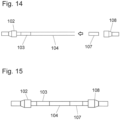
- the second side of the line from step a) has an identification 106 which is arranged on or on the line.
- This identifier 106 includes information for creating a second identifier carrier 107 for identifying a second of the two connection points.
- the identifier 106 can be embodied as a code 110 which identifies the line 101 itself or the identifier carrier 107 to be attached.
- the identifier 106 can be, for example, a wrap-around label with a barcode or QR code.
- This marking 106 is located on the first line 105 after it has been cut to length.
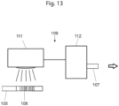
- the identification can be read out in a step c) by a reading device 109, for example comprising a scanner 111 and a printer 112, and creating the second identification carrier 107 for identifying the second connection point in the electrical assembly arrangement. This is in 13 shown.
- the reading device can be designed, for example, as a station where a scanner reads the code and a printer provides the required identifier on an identification carrier.
- the second identification carrier 107 is applied to the second line 104 in a step d). The same applies to a second line connector 108. This is shown schematically in 14 shown.
- the method can thus additionally solve the problem of assigning an identification carrier to a line if the line has to be cut off before installation and the identification carrier to be used cannot be moved.
Landscapes
- Physics & Mathematics (AREA)
- General Physics & Mathematics (AREA)
- Engineering & Computer Science (AREA)
- Geometry (AREA)
- Computer Vision & Pattern Recognition (AREA)
- Theoretical Computer Science (AREA)
- Electric Cable Installation (AREA)
- Manufacturing Of Electric Cables (AREA)
- Insulated Conductors (AREA)
- Communication Control (AREA)
Claims (11)
- Procédé pour déterminer une longueur (I2) d'une deuxième ligne électrique (L2) partiellement préparée, dans lequel la deuxième ligne électrique (L2) partiellement préparée et une première ligne électrique (L1) ayant une longueur (11) et un marquage (KX) sont obtenues par recoupe d'une ligne partiellement préparée (L0) ayant la longueur initiale (I0) et le marquage (KX),dans lequel la ligne (L0) partiellement préparée est conformée comme une ligne unique ou comme un faisceau de câbles avec plusieurs autres lignes partiellement préparées pour le câblage d'une disposition de montage,dans lequel le marquage (KX) détermine un type de ligne, le marquage (KX) contenant des informations sur les branchements d'appareillages électriques auxquels la deuxième ligne électrique (L2) doit être raccordée dans la disposition de montage électrique, etdans lequel le procédé comprend au moins les étapes suivantes :a) détermination (S3) de la longueur (11) de la première ligne électrique (L1) par un dispositif pour la détermination de la longueur des lignes,b) détermination (S4) d'un identifiant de la première ligne électrique (L1) par la reconnaissance du marquage (KX) de la première ligne électrique (L1),c) détermination (S5) de la longueur (I2) de la deuxième ligne électrique destinée à être installée dans une disposition de montage électrique, à l'aide de la longueur (11) de la première ligne électrique (L1) et de la longueur initiale (I0) déterminée à l'aide de l'identifiant.
- Procédé selon la revendication 1, caractérisé en ce que l'identifiant permet d'identifier la première ligne électrique (L1) et la longueur initiale (I0) est déterminée à partir de cette détermination.
- Procédé selon l'une des revendications 1 et/ou 2, caractérisé en ce qu'il comprend en outre une ou plusieurs des étapes suivantes :
recoupe (S1) d'au moins une ligne électrique (L) à une longueur initiale (l0) et/ou affectation (S2) d'un identifiant à la longueur initiale (l0) et/ou enregistrement de la longueur initiale (I0) et d'un identifiant associé. - Procédé selon l'une des revendications précédentes, caractérisé en ce qu'il comprend en outre l'étape suivante :
marquage d'une ligne électrique (L, La, L1, L2) avec un marquage (KX) correspondant à l'identifiant, lequel marquage (KX), est de préférence apposé à la surface, de préférence sur la surface, de la ligne (L, La, L1, L2). - Procédé selon l'une des revendications précédentes, caractérisé en ce qu'il comprend en outre l'étape suivante :
recoupe de la ligne électrique (L0) pour le câblage d'une disposition de montage électrique, qui donne une première ligne électrique (L1) en excédent et une deuxième ligne électrique (L2) destinée à être utilisée dans la disposition de montage électrique. - Procédé selon la revendication 4, caractérisé en ce qu'il comprend en outre au moins une des étapes suivantes :
saisie du marquage (KX) de la première ligne (L1) ou de la deuxième ligne (L2), de préférence au moyen d'une reconnaissance d'image, et détermination d'un identifiant à l'aide du marquage (KX) saisi. - Procédé pour la fabrication d'un premier jeu de câblage composé de lignes électriques munies chacune d'au moins un marquage (KX), chacun de ces marquages (KX) pouvant être affecté à une longueur initiale (I0), par exemple à l'aide d'un identifiant qui peut être déterminé au moyen du marquage (KX), et exécution d'un procédé selon l'une des revendications précédentes pour chacune des lignes électriques du jeu de câblage.
- Procédé pour la fabrication d'un deuxième jeu de lignes électriques, dans lequel le premier jeu de câblage composé de lignes électriques est fabriqué par un procédé selon la revendication 7 et dans lequel le premier jeu de câblage est destiné à une première armoire électrique et le deuxième jeu à une deuxième armoire électrique, caractérisé en ce que, lors de la fabrication du deuxième jeu de câblage, un plan spécifique de l'armoire électrique et/ou une documentation spécifique de l'armoire électrique pour la première armoire électrique sont comparés à un plan spécifique de l'armoire électrique et/ou à une documentation spécifique de l'armoire électrique pour la deuxième armoire électrique et les lignes du deuxième jeu de câblage qui sont réalisées à l'identique dans la première et la deuxième armoire électrique sont préparées.
- Procédé selon la revendication 8, caractérisé en ce que les lignes qui ne sont pas réalisées à l'identique sont présentes dans le deuxième jeu de câblage avec une longueur initiale (l0) ou sont omises.
- Dispositif (V1) pour la détermination de la longueur de lignes, comprenant : une unité de reconnaissance (EE) qui sert à déterminer un identifiant d'une première ligne électrique (L1) apposé sous la forme d'un marquage à la surface ou sur la surface de la ligne (L1), lequel identifiant permet de déterminer le type de ligne de la ligne, le type de ligne contenant des informations sur une ou plusieurs désignations de branchements auxquels les extrémités d'une deuxième ligne doivent être raccordées, une unité de mesure de la longueur (LE) servant à déterminer une longueur (11) de la première ligne (L1), ainsi qu'une unité de mémoire (SE) en liaison opérationnelle avec l'unité de reconnaissance (EE) et l'unité de mesure de la longueur (LE), qui sert à saisir l'identifiant et la longueur (11) de la première ligne (L1), en particulier à les associer l'un à l'autre, le dispositif comprenant une unité de détection (DE1) qui sert à déterminer l'insertion de la première ligne dans le dispositif, en particulier le point où débute la mesure de la longueur, et le dispositif comprenant une deuxième unité de détection (DE2) pour la détection d'une fin de la ligne.
- Dispositif (V1) pour la détermination de la longueur de lignes selon la revendication 10, caractérisé en ce que le dispositif comprend une unité d'acheminement de lignes (TE) pour le transport de lignes ayant des diamètres de conducteurs différents, laquelle unité d'acheminement de lignes (TE) présente des pistes (220, 230) ayant une profondeur de rainure et/ou une largeur de rainure différentes, chaque ligne étant amenée à la piste correspondante en fonction d'un diamètre de conducteur déterminé et/ou d'une grandeur dépendant de celui-ci, en particulier de la section du conducteur.
Applications Claiming Priority (3)
| Application Number | Priority Date | Filing Date | Title |
|---|---|---|---|
| DE102017203552 | 2017-03-03 | ||
| DE102017127792.7A DE102017127792A1 (de) | 2017-03-03 | 2017-11-24 | Vorrichtung und Verfahren zur Leitungslängenbestimmung |
| PCT/EP2018/055026 WO2018158359A1 (fr) | 2017-03-03 | 2018-03-01 | Dispositif et procédé de détermination de la longueur de lignes |
Publications (3)
| Publication Number | Publication Date |
|---|---|
| EP3589916A1 EP3589916A1 (fr) | 2020-01-08 |
| EP3589916B1 true EP3589916B1 (fr) | 2023-08-02 |
| EP3589916C0 EP3589916C0 (fr) | 2023-08-02 |
Family
ID=63171449
Family Applications (1)
| Application Number | Title | Priority Date | Filing Date |
|---|---|---|---|
| EP18708969.3A Active EP3589916B1 (fr) | 2017-03-03 | 2018-03-01 | Dispositif et procédé de détermination de la longueur de lignes |
Country Status (9)
| Country | Link |
|---|---|
| US (1) | US11682132B2 (fr) |
| EP (1) | EP3589916B1 (fr) |
| CN (1) | CN110621958B (fr) |
| DE (1) | DE102017127792A1 (fr) |
| ES (1) | ES2961934T3 (fr) |
| MX (1) | MX2019010304A (fr) |
| PL (1) | PL3589916T3 (fr) |
| RU (1) | RU2720653C1 (fr) |
| WO (1) | WO2018158359A1 (fr) |
Families Citing this family (3)
| Publication number | Priority date | Publication date | Assignee | Title |
|---|---|---|---|---|
| BE1027646B1 (de) * | 2019-10-09 | 2021-05-11 | Phoenix Contact Gmbh & Co | Technik zur Kennzeichnung eines prolaten Objekts |
| WO2021258203A1 (fr) * | 2020-06-23 | 2021-12-30 | 2252778 Alberta Inc. | Procédés et appareil de pose à distance de câble |
| RU213269U1 (ru) * | 2022-05-27 | 2022-09-05 | Общество С Ограниченной Ответственностью "Термоэлектрика" | Устройство маркировки элементов электрооборудования для регистрации максимальной температуры перегрева поверхности оборудования |
Family Cites Families (24)
| Publication number | Priority date | Publication date | Assignee | Title |
|---|---|---|---|---|
| DE3108975A1 (de) * | 1981-03-10 | 1982-09-23 | Walter Hofmann, Maschinenfabrik, 2084 Rellingen | Anordnung zur messung der laenge von leitlinien |
| JPS6039787A (ja) * | 1983-08-12 | 1985-03-01 | 住友電気工業株式会社 | 端子圧着電線の自動成形装置 |
| JP3013674B2 (ja) * | 1993-11-12 | 2000-02-28 | 住友電装株式会社 | 電線作成用制御装置およびその制御装置を含む電線計測切断装置 |
| DE4400824A1 (de) | 1994-01-13 | 1995-07-20 | Siemens Ag | Verfahren und Vorrichtung zur Längenmessung eines langgestreckten Übertragungselements |
| JPH08190814A (ja) * | 1995-01-09 | 1996-07-23 | Sumitomo Electric Ind Ltd | 長尺ケーブル及びケーブル識別方法 |
| JPH08327345A (ja) * | 1995-05-26 | 1996-12-13 | Denshi Insatsu Kikaku:Kk | 電線長計算装置及び電線加工システム |
| JP2001519998A (ja) * | 1997-04-14 | 2001-10-23 | シュロイニヒャー ホルディング アー ゲー | 絶縁被覆除去装置 |
| DE19814540A1 (de) * | 1998-04-01 | 1999-10-28 | Itv Ges Fuer Ind Tv Mbh | Kabel und Meßvorrichtung für Kabellängen |
| DE19831090A1 (de) | 1998-07-10 | 2000-01-27 | Kolb Elektro Sbw Ag Vaduz | Vorkonfektioniertes Elektroinstallations-Kabel |
| JP2000055604A (ja) * | 1998-08-11 | 2000-02-25 | Hitachi Cable Ltd | ケーブルの条長確認方法 |
| DE19918212A1 (de) | 1999-04-22 | 2000-11-09 | Cad Cabel Inh Peter Hanzel | Kabel zur Verdrahtung von elektrischen Geräten einer komplexen, individuellen Anlage und Verfahren zu deren Herstellung |
| DE19939638A1 (de) | 1999-08-20 | 2001-03-29 | Kolb Elektro Sbw Ag Vaduz | Verfahren zum Orten einer Störstelle an einem Kabel für die Stromversorgung und/oder die Datenübertragung und dafür geeignete Kabel |
| DE10248411A1 (de) | 2002-10-17 | 2004-04-29 | Mastnak, Wolfgang Richard | Digitales Kabel-Messgerät |
| JP2004356022A (ja) * | 2003-05-30 | 2004-12-16 | Yazaki Corp | ワイヤハーネスの組立方法とワイヤハーネス |
| JP2005276732A (ja) * | 2004-03-26 | 2005-10-06 | Audio Technica Corp | ケーブル |
| DE102008003593A1 (de) * | 2008-01-09 | 2009-07-23 | Ipek Spezial-Tv Gmbh & Co. Kg | Elektronische Längenmessvorrichtung für ein Kabel und Verfahren zur Positionsbestimmung eines ersten Endes eines Kabels |
| DE102009015263A1 (de) | 2009-04-01 | 2010-10-14 | Areva Np Gmbh | Kabel |
| CN102122806A (zh) * | 2010-12-24 | 2011-07-13 | 南京南车浦镇城轨车辆有限责任公司 | 地铁车辆数字化模板布线方法 |
| FR2970579B1 (fr) * | 2011-01-13 | 2013-01-11 | Peugeot Citroen Automobiles Sa | Dispositif et procede de calcul de sections optimales de troncons d'au moins une ligne electrique en fonction de la chute de tension maximale autorisee sur cette ligne |
| FR2995126B1 (fr) * | 2012-09-06 | 2014-09-19 | Nexans | Dispositif de marquage d'un cable |
| CN103057098B (zh) * | 2013-01-05 | 2014-09-10 | 常熟市谷雷特机械产品设计有限公司 | 一种可监测线缆印字标识及外形尺寸的系统及监测方法 |
| MA36838A1 (fr) | 2014-03-18 | 2016-01-29 | Oritech Sarl | Dispositif de suivi automatique de l'inventaire des matieres enroulees |
| WO2017005282A1 (fr) * | 2015-07-03 | 2017-01-12 | Siemens Aktiengesellschaft | Câble et outil de câblage d'appareils électriques |
| DE202016102194U1 (de) * | 2016-04-26 | 2016-05-19 | Paul Jehle | Messgerät zum Bestimmen von Kabellängen |
-
2017
- 2017-11-24 DE DE102017127792.7A patent/DE102017127792A1/de active Pending
-
2018
- 2018-03-01 WO PCT/EP2018/055026 patent/WO2018158359A1/fr active Application Filing
- 2018-03-01 EP EP18708969.3A patent/EP3589916B1/fr active Active
- 2018-03-01 RU RU2019128371A patent/RU2720653C1/ru active
- 2018-03-01 ES ES18708969T patent/ES2961934T3/es active Active
- 2018-03-01 PL PL18708969.3T patent/PL3589916T3/pl unknown
- 2018-03-01 MX MX2019010304A patent/MX2019010304A/es unknown
- 2018-03-01 CN CN201880029234.5A patent/CN110621958B/zh active Active
- 2018-03-01 US US16/490,319 patent/US11682132B2/en active Active
Also Published As
| Publication number | Publication date |
|---|---|
| ES2961934T3 (es) | 2024-03-14 |
| EP3589916A1 (fr) | 2020-01-08 |
| EP3589916C0 (fr) | 2023-08-02 |
| MX2019010304A (es) | 2019-11-21 |
| US20200410708A1 (en) | 2020-12-31 |
| RU2720653C1 (ru) | 2020-05-12 |
| CN110621958B (zh) | 2022-06-24 |
| PL3589916T3 (pl) | 2024-01-29 |
| WO2018158359A1 (fr) | 2018-09-07 |
| US11682132B2 (en) | 2023-06-20 |
| DE102017127792A1 (de) | 2018-09-06 |
| CN110621958A (zh) | 2019-12-27 |
Similar Documents
| Publication | Publication Date | Title |
|---|---|---|
| DE102009015263A1 (de) | Kabel | |
| EP3589916B1 (fr) | Dispositif et procédé de détermination de la longueur de lignes | |
| EP2930805B1 (fr) | Procédé, dispositif et système de détermination d'une position angulaire de conducteurs individuels sur un point de section transversale dans un conducteur sous gaine à plusieurs fils | |
| DE212019000144U1 (de) | Modulares Kabelverarbeitungscenter | |
| WO2017005282A1 (fr) | Câble et outil de câblage d'appareils électriques | |
| EP1095382A1 (fr) | Cable prefabrique pour installation electrique | |
| EP3207600B1 (fr) | Séquence de câbles pour le câblage d'un circuit électrique, procédé de fabrication et utilisation | |
| DE102015103444B4 (de) | Kabelsequenz für eine Verdrahtung einer elektrischen Schaltung, Verfahren zum Herstellen sowie Verwendung | |
| DE102019119660A1 (de) | Verfahren, Vorrichtung und System zur Konfektionierung eines elektrischen Kabels | |
| EP3534470A1 (fr) | Procédé de câblage de deux points de raccordement d'un dispositif de montage électrique avec un câble électrique partiellement préconfectionné | |
| DE4218985A1 (de) | Verfahren zur erkennung der einzelnen kabel eines kabelbaums bzw. der einzelnen adern eines mehrfachkabels sowie vorrichtung zur durchfuehrung des verfahrens | |
| EP1171891A1 (fr) | Cables pour le cablage d'appareils electriques d'une installation individuelle complexe, et leur procede de realisation | |
| DE19939638A1 (de) | Verfahren zum Orten einer Störstelle an einem Kabel für die Stromversorgung und/oder die Datenübertragung und dafür geeignete Kabel | |
| EP1369971A9 (fr) | Dispositif et procédé pour l'usinage de câbles | |
| WO2020260216A1 (fr) | Procédé, dispositif et système destinés à la confection d'un câble électrique | |
| DE102005026892B4 (de) | Einrichtung und Verfahren zur Unterstützung des Einbaus von elektrischen Leitungen | |
| DE102019119725A1 (de) | Verfahren, Vorrichtung und System zur Konfektionierung eines elektrischen Kabels | |
| EP4055675A1 (fr) | Tube ondulé comprenant un support d'informations | |
| DE202018101150U1 (de) | Vorrichtung zur Längenleitungsbestimmung | |
| EP0794597A1 (fr) | Machine pour la production automatique de câbles, comportant une terminaison à un bout au-moins | |
| DE202021104090U1 (de) | Technik zur Kennzeichnung eines prolaten Objekts | |
| DE102021119898A1 (de) | Technik zur Kennzeichnung eines prolaten Objekts | |
| DE2714866A1 (de) | Einrichtung zum maschinenlesen optischer codierungen | |
| EP1308563A2 (fr) | Dispositif d'enregistrement pour un dispositif d' installation dans le domaine d'installations sanitaires et méthode de régistration | |
| DD141590A1 (de) | Einrichtung zur verdrahtungsgerechten vorfertigung elektrischer leitungen |
Legal Events
| Date | Code | Title | Description |
|---|---|---|---|
| STAA | Information on the status of an ep patent application or granted ep patent |
Free format text: STATUS: UNKNOWN |
|
| STAA | Information on the status of an ep patent application or granted ep patent |
Free format text: STATUS: THE INTERNATIONAL PUBLICATION HAS BEEN MADE |
|
| PUAI | Public reference made under article 153(3) epc to a published international application that has entered the european phase |
Free format text: ORIGINAL CODE: 0009012 |
|
| STAA | Information on the status of an ep patent application or granted ep patent |
Free format text: STATUS: REQUEST FOR EXAMINATION WAS MADE |
|
| 17P | Request for examination filed |
Effective date: 20190926 |
|
| AK | Designated contracting states |
Kind code of ref document: A1 Designated state(s): AL AT BE BG CH CY CZ DE DK EE ES FI FR GB GR HR HU IE IS IT LI LT LU LV MC MK MT NL NO PL PT RO RS SE SI SK SM TR |
|
| AX | Request for extension of the european patent |
Extension state: BA ME |
|
| DAV | Request for validation of the european patent (deleted) | ||
| DAX | Request for extension of the european patent (deleted) | ||
| STAA | Information on the status of an ep patent application or granted ep patent |
Free format text: STATUS: EXAMINATION IS IN PROGRESS |
|
| STAA | Information on the status of an ep patent application or granted ep patent |
Free format text: STATUS: EXAMINATION IS IN PROGRESS |
|
| 17Q | First examination report despatched |
Effective date: 20211006 |
|
| REG | Reference to a national code |
Ref country code: DE Ref legal event code: R079 Ref document number: 502018012852 Country of ref document: DE Free format text: PREVIOUS MAIN CLASS: G01B0021060000 Ipc: G01B0005040000 Ref legal event code: R079 Ipc: G01B0005040000 |
|
| GRAP | Despatch of communication of intention to grant a patent |
Free format text: ORIGINAL CODE: EPIDOSNIGR1 |
|
| STAA | Information on the status of an ep patent application or granted ep patent |
Free format text: STATUS: GRANT OF PATENT IS INTENDED |
|
| RIC1 | Information provided on ipc code assigned before grant |
Ipc: H02G 3/00 20060101ALN20230209BHEP Ipc: H01B 7/36 20060101ALN20230209BHEP Ipc: H02G 1/00 20060101ALI20230209BHEP Ipc: G01B 21/06 20060101ALI20230209BHEP Ipc: G01B 21/02 20060101ALI20230209BHEP Ipc: G01B 11/04 20060101ALI20230209BHEP Ipc: G01B 7/02 20060101ALI20230209BHEP Ipc: G01B 5/04 20060101AFI20230209BHEP |
|
| INTG | Intention to grant announced |
Effective date: 20230227 |
|
| GRAS | Grant fee paid |
Free format text: ORIGINAL CODE: EPIDOSNIGR3 |
|
| GRAA | (expected) grant |
Free format text: ORIGINAL CODE: 0009210 |
|
| STAA | Information on the status of an ep patent application or granted ep patent |
Free format text: STATUS: THE PATENT HAS BEEN GRANTED |
|
| AK | Designated contracting states |
Kind code of ref document: B1 Designated state(s): AL AT BE BG CH CY CZ DE DK EE ES FI FR GB GR HR HU IE IS IT LI LT LU LV MC MK MT NL NO PL PT RO RS SE SI SK SM TR |
|
| REG | Reference to a national code |
Ref country code: GB Ref legal event code: FG4D Free format text: NOT ENGLISH |
|
| REG | Reference to a national code |
Ref country code: CH Ref legal event code: EP |
|
| REG | Reference to a national code |
Ref country code: DE Ref legal event code: R096 Ref document number: 502018012852 Country of ref document: DE |
|
| REG | Reference to a national code |
Ref country code: IE Ref legal event code: FG4D Free format text: LANGUAGE OF EP DOCUMENT: GERMAN |
|
| U01 | Request for unitary effect filed |
Effective date: 20230829 |
|
| U07 | Unitary effect registered |
Designated state(s): AT BE BG DE DK EE FI FR IT LT LU LV MT NL PT SE SI Effective date: 20230904 |
|
| PG25 | Lapsed in a contracting state [announced via postgrant information from national office to epo] |
Ref country code: GR Free format text: LAPSE BECAUSE OF FAILURE TO SUBMIT A TRANSLATION OF THE DESCRIPTION OR TO PAY THE FEE WITHIN THE PRESCRIBED TIME-LIMIT Effective date: 20231103 |
|
| PG25 | Lapsed in a contracting state [announced via postgrant information from national office to epo] |
Ref country code: IS Free format text: LAPSE BECAUSE OF FAILURE TO SUBMIT A TRANSLATION OF THE DESCRIPTION OR TO PAY THE FEE WITHIN THE PRESCRIBED TIME-LIMIT Effective date: 20231202 |
|
| PG25 | Lapsed in a contracting state [announced via postgrant information from national office to epo] |
Ref country code: RS Free format text: LAPSE BECAUSE OF FAILURE TO SUBMIT A TRANSLATION OF THE DESCRIPTION OR TO PAY THE FEE WITHIN THE PRESCRIBED TIME-LIMIT Effective date: 20230802 Ref country code: NO Free format text: LAPSE BECAUSE OF FAILURE TO SUBMIT A TRANSLATION OF THE DESCRIPTION OR TO PAY THE FEE WITHIN THE PRESCRIBED TIME-LIMIT Effective date: 20231102 Ref country code: IS Free format text: LAPSE BECAUSE OF FAILURE TO SUBMIT A TRANSLATION OF THE DESCRIPTION OR TO PAY THE FEE WITHIN THE PRESCRIBED TIME-LIMIT Effective date: 20231202 Ref country code: HR Free format text: LAPSE BECAUSE OF FAILURE TO SUBMIT A TRANSLATION OF THE DESCRIPTION OR TO PAY THE FEE WITHIN THE PRESCRIBED TIME-LIMIT Effective date: 20230802 Ref country code: GR Free format text: LAPSE BECAUSE OF FAILURE TO SUBMIT A TRANSLATION OF THE DESCRIPTION OR TO PAY THE FEE WITHIN THE PRESCRIBED TIME-LIMIT Effective date: 20231103 |
|
| REG | Reference to a national code |
Ref country code: ES Ref legal event code: FG2A Ref document number: 2961934 Country of ref document: ES Kind code of ref document: T3 Effective date: 20240314 |
|
| PG25 | Lapsed in a contracting state [announced via postgrant information from national office to epo] |
Ref country code: SM Free format text: LAPSE BECAUSE OF FAILURE TO SUBMIT A TRANSLATION OF THE DESCRIPTION OR TO PAY THE FEE WITHIN THE PRESCRIBED TIME-LIMIT Effective date: 20230802 Ref country code: RO Free format text: LAPSE BECAUSE OF FAILURE TO SUBMIT A TRANSLATION OF THE DESCRIPTION OR TO PAY THE FEE WITHIN THE PRESCRIBED TIME-LIMIT Effective date: 20230802 Ref country code: CZ Free format text: LAPSE BECAUSE OF FAILURE TO SUBMIT A TRANSLATION OF THE DESCRIPTION OR TO PAY THE FEE WITHIN THE PRESCRIBED TIME-LIMIT Effective date: 20230802 Ref country code: SK Free format text: LAPSE BECAUSE OF FAILURE TO SUBMIT A TRANSLATION OF THE DESCRIPTION OR TO PAY THE FEE WITHIN THE PRESCRIBED TIME-LIMIT Effective date: 20230802 |
|
| U20 | Renewal fee paid [unitary effect] |
Year of fee payment: 7 Effective date: 20240326 |