EP3587316A1 - Stanzteilapplikator und verfahren zum aufbringen von stanzteilen auf oberflächen sowie ein stanzteilband - Google Patents
Stanzteilapplikator und verfahren zum aufbringen von stanzteilen auf oberflächen sowie ein stanzteilband Download PDFInfo
- Publication number
- EP3587316A1 EP3587316A1 EP19180431.9A EP19180431A EP3587316A1 EP 3587316 A1 EP3587316 A1 EP 3587316A1 EP 19180431 A EP19180431 A EP 19180431A EP 3587316 A1 EP3587316 A1 EP 3587316A1
- Authority
- EP
- European Patent Office
- Prior art keywords
- stamped
- stamped part
- parts
- tape
- stamp
- Prior art date
- Legal status (The legal status is an assumption and is not a legal conclusion. Google has not performed a legal analysis and makes no representation as to the accuracy of the status listed.)
- Withdrawn
Links
- 238000000034 method Methods 0.000 title claims description 16
- 239000012790 adhesive layer Substances 0.000 claims abstract description 41
- 239000010410 layer Substances 0.000 claims abstract description 33
- 230000000295 complement effect Effects 0.000 claims abstract description 14
- 238000004804 winding Methods 0.000 claims description 26
- 239000000853 adhesive Substances 0.000 claims description 16
- 230000001070 adhesive effect Effects 0.000 claims description 16
- 238000001514 detection method Methods 0.000 claims 1
- RTZKZFJDLAIYFH-UHFFFAOYSA-N Diethyl ether Chemical compound CCOCC RTZKZFJDLAIYFH-UHFFFAOYSA-N 0.000 description 8
- -1 Polyethylene Polymers 0.000 description 7
- 229920005989 resin Polymers 0.000 description 6
- 239000011347 resin Substances 0.000 description 6
- 229920003986 novolac Polymers 0.000 description 4
- XEKOWRVHYACXOJ-UHFFFAOYSA-N Ethyl acetate Chemical compound CCOC(C)=O XEKOWRVHYACXOJ-UHFFFAOYSA-N 0.000 description 3
- 239000004820 Pressure-sensitive adhesive Substances 0.000 description 3
- 229920001400 block copolymer Polymers 0.000 description 3
- 150000004292 cyclic ethers Chemical class 0.000 description 3
- 229920001971 elastomer Polymers 0.000 description 3
- 239000000806 elastomer Substances 0.000 description 3
- 239000002904 solvent Substances 0.000 description 3
- YXALYBMHAYZKAP-UHFFFAOYSA-N 7-oxabicyclo[4.1.0]heptan-4-ylmethyl 7-oxabicyclo[4.1.0]heptane-4-carboxylate Chemical compound C1CC2OC2CC1C(=O)OCC1CC2OC2CC1 YXALYBMHAYZKAP-UHFFFAOYSA-N 0.000 description 2
- LCFVJGUPQDGYKZ-UHFFFAOYSA-N Bisphenol A diglycidyl ether Chemical compound C=1C=C(OCC2OC2)C=CC=1C(C)(C)C(C=C1)=CC=C1OCC1CO1 LCFVJGUPQDGYKZ-UHFFFAOYSA-N 0.000 description 2
- 229920000089 Cyclic olefin copolymer Polymers 0.000 description 2
- 239000004713 Cyclic olefin copolymer Substances 0.000 description 2
- 239000002033 PVDF binder Substances 0.000 description 2
- 239000004952 Polyamide Substances 0.000 description 2
- 239000005062 Polybutadiene Substances 0.000 description 2
- 239000004642 Polyimide Substances 0.000 description 2
- QYKIQEUNHZKYBP-UHFFFAOYSA-N Vinyl ether Chemical class C=COC=C QYKIQEUNHZKYBP-UHFFFAOYSA-N 0.000 description 2
- IISBACLAFKSPIT-UHFFFAOYSA-N bisphenol A Chemical compound C=1C=C(O)C=CC=1C(C)(C)C1=CC=C(O)C=C1 IISBACLAFKSPIT-UHFFFAOYSA-N 0.000 description 2
- XUCHXOAWJMEFLF-UHFFFAOYSA-N bisphenol F diglycidyl ether Chemical compound C1OC1COC(C=C1)=CC=C1CC(C=C1)=CC=C1OCC1CO1 XUCHXOAWJMEFLF-UHFFFAOYSA-N 0.000 description 2
- 150000001875 compounds Chemical class 0.000 description 2
- 229920001577 copolymer Polymers 0.000 description 2
- 239000007788 liquid Substances 0.000 description 2
- 229920002239 polyacrylonitrile Polymers 0.000 description 2
- 229920002647 polyamide Polymers 0.000 description 2
- 229920002857 polybutadiene Polymers 0.000 description 2
- 229920000139 polyethylene terephthalate Polymers 0.000 description 2
- 239000005020 polyethylene terephthalate Substances 0.000 description 2
- 229920001721 polyimide Polymers 0.000 description 2
- 229920001195 polyisoprene Polymers 0.000 description 2
- 229920000642 polymer Polymers 0.000 description 2
- 229920002981 polyvinylidene fluoride Polymers 0.000 description 2
- 239000011877 solvent mixture Substances 0.000 description 2
- UNMJLQGKEDTEKJ-UHFFFAOYSA-N (3-ethyloxetan-3-yl)methanol Chemical compound CCC1(CO)COC1 UNMJLQGKEDTEKJ-UHFFFAOYSA-N 0.000 description 1
- PSGCQDPCAWOCSH-UHFFFAOYSA-N (4,7,7-trimethyl-3-bicyclo[2.2.1]heptanyl) prop-2-enoate Chemical compound C1CC2(C)C(OC(=O)C=C)CC1C2(C)C PSGCQDPCAWOCSH-UHFFFAOYSA-N 0.000 description 1
- SHKUUQIDMUMQQK-UHFFFAOYSA-N 2-[4-(oxiran-2-ylmethoxy)butoxymethyl]oxirane Chemical compound C1OC1COCCCCOCC1CO1 SHKUUQIDMUMQQK-UHFFFAOYSA-N 0.000 description 1
- PLDLPVSQYMQDBL-UHFFFAOYSA-N 2-[[3-(oxiran-2-ylmethoxy)-2,2-bis(oxiran-2-ylmethoxymethyl)propoxy]methyl]oxirane Chemical compound C1OC1COCC(COCC1OC1)(COCC1OC1)COCC1CO1 PLDLPVSQYMQDBL-UHFFFAOYSA-N 0.000 description 1
- VQMQXWYQIIUJIT-UHFFFAOYSA-N 2-[[4-(oxiran-2-ylmethoxymethyl)cyclohexyl]methoxymethyl]oxirane Chemical class C1OC1COCC(CC1)CCC1COCC1CO1 VQMQXWYQIIUJIT-UHFFFAOYSA-N 0.000 description 1
- HLQNHQOKIVRFLM-UHFFFAOYSA-N 3-[1-[1-(oxetan-3-yl)propoxy]propyl]oxetane Chemical compound C1OCC1C(CC)OC(CC)C1COC1 HLQNHQOKIVRFLM-UHFFFAOYSA-N 0.000 description 1
- WRQOPPZJPSGEDO-UHFFFAOYSA-N 5-oxabicyclo[4.1.0]heptane Chemical compound C1CCOC2CC21 WRQOPPZJPSGEDO-UHFFFAOYSA-N 0.000 description 1
- VQTUBCCKSQIDNK-UHFFFAOYSA-N Isobutene Chemical group CC(C)=C VQTUBCCKSQIDNK-UHFFFAOYSA-N 0.000 description 1
- VVQNEPGJFQJSBK-UHFFFAOYSA-N Methyl methacrylate Chemical compound COC(=O)C(C)=C VVQNEPGJFQJSBK-UHFFFAOYSA-N 0.000 description 1
- 240000001439 Opuntia Species 0.000 description 1
- 235000004727 Opuntia ficus indica Nutrition 0.000 description 1
- 229920012266 Poly(ether sulfone) PES Polymers 0.000 description 1
- 239000004698 Polyethylene Substances 0.000 description 1
- 239000002202 Polyethylene glycol Substances 0.000 description 1
- 229920002367 Polyisobutene Polymers 0.000 description 1
- 239000004743 Polypropylene Substances 0.000 description 1
- IAXXETNIOYFMLW-COPLHBTASA-N [(1s,3s,4s)-4,7,7-trimethyl-3-bicyclo[2.2.1]heptanyl] 2-methylprop-2-enoate Chemical compound C1C[C@]2(C)[C@@H](OC(=O)C(=C)C)C[C@H]1C2(C)C IAXXETNIOYFMLW-COPLHBTASA-N 0.000 description 1
- NRJLSUZLHMXXHJ-UHFFFAOYSA-N [4-(7-oxabicyclo[4.1.0]heptane-4-carbonyloxymethyl)cyclohexyl]methyl 7-oxabicyclo[4.1.0]heptane-4-carboxylate Chemical compound C1CC2OC2CC1C(=O)OCC1CCC(COC(=O)C2CC3OC3CC2)CC1 NRJLSUZLHMXXHJ-UHFFFAOYSA-N 0.000 description 1
- 238000004026 adhesive bonding Methods 0.000 description 1
- 239000002313 adhesive film Substances 0.000 description 1
- 150000001298 alcohols Chemical class 0.000 description 1
- 125000001931 aliphatic group Chemical group 0.000 description 1
- 125000003118 aryl group Chemical group 0.000 description 1
- DJUWPHRCMMMSCV-UHFFFAOYSA-N bis(7-oxabicyclo[4.1.0]heptan-4-ylmethyl) hexanedioate Chemical compound C1CC2OC2CC1COC(=O)CCCCC(=O)OCC1CC2OC2CC1 DJUWPHRCMMMSCV-UHFFFAOYSA-N 0.000 description 1
- RUNBDQGENXJZOO-UHFFFAOYSA-N bis(oxiran-2-ylmethyl) 7-oxabicyclo[4.1.0]hept-5-ene-3,4-dicarboxylate Chemical compound C1C2OC2=CC(C(=O)OCC2OC2)C1C(=O)OCC1CO1 RUNBDQGENXJZOO-UHFFFAOYSA-N 0.000 description 1
- KTPIWUHKYIJBCR-UHFFFAOYSA-N bis(oxiran-2-ylmethyl) cyclohex-4-ene-1,2-dicarboxylate Chemical compound C1C=CCC(C(=O)OCC2OC2)C1C(=O)OCC1CO1 KTPIWUHKYIJBCR-UHFFFAOYSA-N 0.000 description 1
- 238000004132 cross linking Methods 0.000 description 1
- OIWOHHBRDFKZNC-UHFFFAOYSA-N cyclohexyl 2-methylprop-2-enoate Chemical compound CC(=C)C(=O)OC1CCCCC1 OIWOHHBRDFKZNC-UHFFFAOYSA-N 0.000 description 1
- BQQUFAMSJAKLNB-UHFFFAOYSA-N dicyclopentadiene diepoxide Chemical compound C12C(C3OC33)CC3C2CC2C1O2 BQQUFAMSJAKLNB-UHFFFAOYSA-N 0.000 description 1
- 150000002118 epoxides Chemical class 0.000 description 1
- 150000002148 esters Chemical class 0.000 description 1
- 239000004715 ethylene vinyl alcohol Substances 0.000 description 1
- 239000003292 glue Substances 0.000 description 1
- 229920001519 homopolymer Polymers 0.000 description 1
- 229910052739 hydrogen Inorganic materials 0.000 description 1
- 239000001257 hydrogen Substances 0.000 description 1
- 229940119545 isobornyl methacrylate Drugs 0.000 description 1
- 238000003754 machining Methods 0.000 description 1
- 238000004519 manufacturing process Methods 0.000 description 1
- 239000000463 material Substances 0.000 description 1
- 239000000203 mixture Substances 0.000 description 1
- 239000012454 non-polar solvent Substances 0.000 description 1
- 239000005026 oriented polypropylene Substances 0.000 description 1
- 150000002921 oxetanes Chemical class 0.000 description 1
- 125000000466 oxiranyl group Chemical group 0.000 description 1
- 229920003023 plastic Polymers 0.000 description 1
- 239000004033 plastic Substances 0.000 description 1
- 229920001748 polybutylene Polymers 0.000 description 1
- 239000004417 polycarbonate Substances 0.000 description 1
- 229920000515 polycarbonate Polymers 0.000 description 1
- 229920000728 polyester Polymers 0.000 description 1
- 229920000570 polyether Polymers 0.000 description 1
- 229920000573 polyethylene Polymers 0.000 description 1
- 229920001223 polyethylene glycol Polymers 0.000 description 1
- 239000011112 polyethylene naphthalate Substances 0.000 description 1
- 229920000098 polyolefin Polymers 0.000 description 1
- 229920001155 polypropylene Polymers 0.000 description 1
- 229920001451 polypropylene glycol Polymers 0.000 description 1
- 229920000909 polytetrahydrofuran Polymers 0.000 description 1
- 239000004800 polyvinyl chloride Substances 0.000 description 1
- 239000005033 polyvinylidene chloride Substances 0.000 description 1
- 238000000926 separation method Methods 0.000 description 1
- 125000003003 spiro group Chemical group 0.000 description 1
- 239000000126 substance Substances 0.000 description 1
- 238000004381 surface treatment Methods 0.000 description 1
- 125000000383 tetramethylene group Chemical group [H]C([H])([*:1])C([H])([H])C([H])([H])C([H])([H])[*:2] 0.000 description 1
- 125000000391 vinyl group Chemical group [H]C([*])=C([H])[H] 0.000 description 1
- 229920002554 vinyl polymer Polymers 0.000 description 1
Images

Classifications
-
- F—MECHANICAL ENGINEERING; LIGHTING; HEATING; WEAPONS; BLASTING
- F16—ENGINEERING ELEMENTS AND UNITS; GENERAL MEASURES FOR PRODUCING AND MAINTAINING EFFECTIVE FUNCTIONING OF MACHINES OR INSTALLATIONS; THERMAL INSULATION IN GENERAL
- F16B—DEVICES FOR FASTENING OR SECURING CONSTRUCTIONAL ELEMENTS OR MACHINE PARTS TOGETHER, e.g. NAILS, BOLTS, CIRCLIPS, CLAMPS, CLIPS OR WEDGES; JOINTS OR JOINTING
- F16B11/00—Connecting constructional elements or machine parts by sticking or pressing them together, e.g. cold pressure welding
-
- B—PERFORMING OPERATIONS; TRANSPORTING
- B32—LAYERED PRODUCTS
- B32B—LAYERED PRODUCTS, i.e. PRODUCTS BUILT-UP OF STRATA OF FLAT OR NON-FLAT, e.g. CELLULAR OR HONEYCOMB, FORM
- B32B38/00—Ancillary operations in connection with laminating processes
- B32B38/04—Punching, slitting or perforating
-
- B—PERFORMING OPERATIONS; TRANSPORTING
- B65—CONVEYING; PACKING; STORING; HANDLING THIN OR FILAMENTARY MATERIAL
- B65H—HANDLING THIN OR FILAMENTARY MATERIAL, e.g. SHEETS, WEBS, CABLES
- B65H35/00—Delivering articles from cutting or line-perforating machines; Article or web delivery apparatus incorporating cutting or line-perforating devices, e.g. adhesive tape dispensers
- B65H35/0006—Article or web delivery apparatus incorporating cutting or line-perforating devices
- B65H35/0013—Article or web delivery apparatus incorporating cutting or line-perforating devices and applying the article or the web by adhesive to a surface
-
- B—PERFORMING OPERATIONS; TRANSPORTING
- B65—CONVEYING; PACKING; STORING; HANDLING THIN OR FILAMENTARY MATERIAL
- B65H—HANDLING THIN OR FILAMENTARY MATERIAL, e.g. SHEETS, WEBS, CABLES
- B65H37/00—Article or web delivery apparatus incorporating devices for performing specified auxiliary operations
- B65H37/04—Article or web delivery apparatus incorporating devices for performing specified auxiliary operations for securing together articles or webs, e.g. by adhesive, stitching or stapling
-
- B—PERFORMING OPERATIONS; TRANSPORTING
- B32—LAYERED PRODUCTS
- B32B—LAYERED PRODUCTS, i.e. PRODUCTS BUILT-UP OF STRATA OF FLAT OR NON-FLAT, e.g. CELLULAR OR HONEYCOMB, FORM
- B32B37/00—Methods or apparatus for laminating, e.g. by curing or by ultrasonic bonding
- B32B37/0046—Methods or apparatus for laminating, e.g. by curing or by ultrasonic bonding characterised by constructional aspects of the apparatus
-
- B—PERFORMING OPERATIONS; TRANSPORTING
- B32—LAYERED PRODUCTS
- B32B—LAYERED PRODUCTS, i.e. PRODUCTS BUILT-UP OF STRATA OF FLAT OR NON-FLAT, e.g. CELLULAR OR HONEYCOMB, FORM
- B32B37/00—Methods or apparatus for laminating, e.g. by curing or by ultrasonic bonding
- B32B37/10—Methods or apparatus for laminating, e.g. by curing or by ultrasonic bonding characterised by the pressing technique, e.g. using action of vacuum or fluid pressure
- B32B37/1045—Intermittent pressing, e.g. by oscillating or reciprocating motion of the pressing means
-
- B—PERFORMING OPERATIONS; TRANSPORTING
- B32—LAYERED PRODUCTS
- B32B—LAYERED PRODUCTS, i.e. PRODUCTS BUILT-UP OF STRATA OF FLAT OR NON-FLAT, e.g. CELLULAR OR HONEYCOMB, FORM
- B32B37/00—Methods or apparatus for laminating, e.g. by curing or by ultrasonic bonding
- B32B37/12—Methods or apparatus for laminating, e.g. by curing or by ultrasonic bonding characterised by using adhesives
-
- B—PERFORMING OPERATIONS; TRANSPORTING
- B32—LAYERED PRODUCTS
- B32B—LAYERED PRODUCTS, i.e. PRODUCTS BUILT-UP OF STRATA OF FLAT OR NON-FLAT, e.g. CELLULAR OR HONEYCOMB, FORM
- B32B37/00—Methods or apparatus for laminating, e.g. by curing or by ultrasonic bonding
- B32B37/14—Methods or apparatus for laminating, e.g. by curing or by ultrasonic bonding characterised by the properties of the layers
- B32B37/16—Methods or apparatus for laminating, e.g. by curing or by ultrasonic bonding characterised by the properties of the layers with all layers existing as coherent layers before laminating
- B32B37/18—Methods or apparatus for laminating, e.g. by curing or by ultrasonic bonding characterised by the properties of the layers with all layers existing as coherent layers before laminating involving the assembly of discrete sheets or panels only
- B32B37/182—Methods or apparatus for laminating, e.g. by curing or by ultrasonic bonding characterised by the properties of the layers with all layers existing as coherent layers before laminating involving the assembly of discrete sheets or panels only one or more of the layers being plastic
-
- B—PERFORMING OPERATIONS; TRANSPORTING
- B32—LAYERED PRODUCTS
- B32B—LAYERED PRODUCTS, i.e. PRODUCTS BUILT-UP OF STRATA OF FLAT OR NON-FLAT, e.g. CELLULAR OR HONEYCOMB, FORM
- B32B7/00—Layered products characterised by the relation between layers; Layered products characterised by the relative orientation of features between layers, or by the relative values of a measurable parameter between layers, i.e. products comprising layers having different physical, chemical or physicochemical properties; Layered products characterised by the interconnection of layers
- B32B7/04—Interconnection of layers
- B32B7/12—Interconnection of layers using interposed adhesives or interposed materials with bonding properties
-
- B—PERFORMING OPERATIONS; TRANSPORTING
- B65—CONVEYING; PACKING; STORING; HANDLING THIN OR FILAMENTARY MATERIAL
- B65H—HANDLING THIN OR FILAMENTARY MATERIAL, e.g. SHEETS, WEBS, CABLES
- B65H18/00—Winding webs
- B65H18/08—Web-winding mechanisms
- B65H18/10—Mechanisms in which power is applied to web-roll spindle
- B65H18/103—Reel-to-reel type web winding and unwinding mechanisms
-
- B—PERFORMING OPERATIONS; TRANSPORTING
- B65—CONVEYING; PACKING; STORING; HANDLING THIN OR FILAMENTARY MATERIAL
- B65H—HANDLING THIN OR FILAMENTARY MATERIAL, e.g. SHEETS, WEBS, CABLES
- B65H35/00—Delivering articles from cutting or line-perforating machines; Article or web delivery apparatus incorporating cutting or line-perforating devices, e.g. adhesive tape dispensers
- B65H35/10—Delivering articles from cutting or line-perforating machines; Article or web delivery apparatus incorporating cutting or line-perforating devices, e.g. adhesive tape dispensers from or with devices for breaking partially-cut or perforated webs, e.g. bursters
-
- B—PERFORMING OPERATIONS; TRANSPORTING
- B65—CONVEYING; PACKING; STORING; HANDLING THIN OR FILAMENTARY MATERIAL
- B65H—HANDLING THIN OR FILAMENTARY MATERIAL, e.g. SHEETS, WEBS, CABLES
- B65H37/00—Article or web delivery apparatus incorporating devices for performing specified auxiliary operations
- B65H37/002—Web delivery apparatus, the web serving as support for articles, material or another web
- B65H37/005—Hand-held apparatus
- B65H37/007—Applicators for applying coatings, e.g. correction, colour or adhesive coatings
-
- B—PERFORMING OPERATIONS; TRANSPORTING
- B29—WORKING OF PLASTICS; WORKING OF SUBSTANCES IN A PLASTIC STATE IN GENERAL
- B29C—SHAPING OR JOINING OF PLASTICS; SHAPING OF MATERIAL IN A PLASTIC STATE, NOT OTHERWISE PROVIDED FOR; AFTER-TREATMENT OF THE SHAPED PRODUCTS, e.g. REPAIRING
- B29C66/00—General aspects of processes or apparatus for joining preformed parts
- B29C66/90—Measuring or controlling the joining process
- B29C66/92—Measuring or controlling the joining process by measuring or controlling the pressure, the force, the mechanical power or the displacement of the joining tools
- B29C66/924—Measuring or controlling the joining process by measuring or controlling the pressure, the force, the mechanical power or the displacement of the joining tools by controlling or regulating the pressure, the force, the mechanical power or the displacement of the joining tools
- B29C66/9261—Measuring or controlling the joining process by measuring or controlling the pressure, the force, the mechanical power or the displacement of the joining tools by controlling or regulating the pressure, the force, the mechanical power or the displacement of the joining tools by controlling or regulating the displacement of the joining tools
-
- B—PERFORMING OPERATIONS; TRANSPORTING
- B32—LAYERED PRODUCTS
- B32B—LAYERED PRODUCTS, i.e. PRODUCTS BUILT-UP OF STRATA OF FLAT OR NON-FLAT, e.g. CELLULAR OR HONEYCOMB, FORM
- B32B41/00—Arrangements for controlling or monitoring lamination processes; Safety arrangements
- B32B2041/06—Starting the lamination machine or method
-
- B—PERFORMING OPERATIONS; TRANSPORTING
- B32—LAYERED PRODUCTS
- B32B—LAYERED PRODUCTS, i.e. PRODUCTS BUILT-UP OF STRATA OF FLAT OR NON-FLAT, e.g. CELLULAR OR HONEYCOMB, FORM
- B32B2519/00—Labels, badges
-
- B—PERFORMING OPERATIONS; TRANSPORTING
- B32—LAYERED PRODUCTS
- B32B—LAYERED PRODUCTS, i.e. PRODUCTS BUILT-UP OF STRATA OF FLAT OR NON-FLAT, e.g. CELLULAR OR HONEYCOMB, FORM
- B32B2605/00—Vehicles
- B32B2605/08—Cars
-
- B—PERFORMING OPERATIONS; TRANSPORTING
- B32—LAYERED PRODUCTS
- B32B—LAYERED PRODUCTS, i.e. PRODUCTS BUILT-UP OF STRATA OF FLAT OR NON-FLAT, e.g. CELLULAR OR HONEYCOMB, FORM
- B32B37/00—Methods or apparatus for laminating, e.g. by curing or by ultrasonic bonding
- B32B37/06—Methods or apparatus for laminating, e.g. by curing or by ultrasonic bonding characterised by the heating method
-
- B—PERFORMING OPERATIONS; TRANSPORTING
- B65—CONVEYING; PACKING; STORING; HANDLING THIN OR FILAMENTARY MATERIAL
- B65H—HANDLING THIN OR FILAMENTARY MATERIAL, e.g. SHEETS, WEBS, CABLES
- B65H2301/00—Handling processes for sheets or webs
- B65H2301/50—Auxiliary process performed during handling process
- B65H2301/51—Modifying a characteristic of handled material
- B65H2301/515—Cutting handled material
- B65H2301/5151—Cutting handled material transversally to feeding direction
- B65H2301/51514—Breaking; Bursting; Tearing, i.e. cutting without cutting member
-
- B—PERFORMING OPERATIONS; TRANSPORTING
- B65—CONVEYING; PACKING; STORING; HANDLING THIN OR FILAMENTARY MATERIAL
- B65H—HANDLING THIN OR FILAMENTARY MATERIAL, e.g. SHEETS, WEBS, CABLES
- B65H2301/00—Handling processes for sheets or webs
- B65H2301/50—Auxiliary process performed during handling process
- B65H2301/51—Modifying a characteristic of handled material
- B65H2301/516—Securing handled material to another material
- B65H2301/5161—Binding processes
-
- B—PERFORMING OPERATIONS; TRANSPORTING
- B65—CONVEYING; PACKING; STORING; HANDLING THIN OR FILAMENTARY MATERIAL
- B65H—HANDLING THIN OR FILAMENTARY MATERIAL, e.g. SHEETS, WEBS, CABLES
- B65H2301/00—Handling processes for sheets or webs
- B65H2301/50—Auxiliary process performed during handling process
- B65H2301/51—Modifying a characteristic of handled material
- B65H2301/516—Securing handled material to another material
- B65H2301/5163—Applying label, tab to handled material
-
- B—PERFORMING OPERATIONS; TRANSPORTING
- B65—CONVEYING; PACKING; STORING; HANDLING THIN OR FILAMENTARY MATERIAL
- B65H—HANDLING THIN OR FILAMENTARY MATERIAL, e.g. SHEETS, WEBS, CABLES
- B65H2553/00—Sensing or detecting means
- B65H2553/80—Arangement of the sensing means
-
- B—PERFORMING OPERATIONS; TRANSPORTING
- B65—CONVEYING; PACKING; STORING; HANDLING THIN OR FILAMENTARY MATERIAL
- B65H—HANDLING THIN OR FILAMENTARY MATERIAL, e.g. SHEETS, WEBS, CABLES
- B65H2555/00—Actuating means
- B65H2555/30—Multi-axis
-
- B—PERFORMING OPERATIONS; TRANSPORTING
- B65—CONVEYING; PACKING; STORING; HANDLING THIN OR FILAMENTARY MATERIAL
- B65H—HANDLING THIN OR FILAMENTARY MATERIAL, e.g. SHEETS, WEBS, CABLES
- B65H2701/00—Handled material; Storage means
- B65H2701/10—Handled articles or webs
- B65H2701/19—Specific article or web
-
- B—PERFORMING OPERATIONS; TRANSPORTING
- B65—CONVEYING; PACKING; STORING; HANDLING THIN OR FILAMENTARY MATERIAL
- B65H—HANDLING THIN OR FILAMENTARY MATERIAL, e.g. SHEETS, WEBS, CABLES
- B65H2801/00—Application field
- B65H2801/51—Automobile
-
- Y—GENERAL TAGGING OF NEW TECHNOLOGICAL DEVELOPMENTS; GENERAL TAGGING OF CROSS-SECTIONAL TECHNOLOGIES SPANNING OVER SEVERAL SECTIONS OF THE IPC; TECHNICAL SUBJECTS COVERED BY FORMER USPC CROSS-REFERENCE ART COLLECTIONS [XRACs] AND DIGESTS
- Y10—TECHNICAL SUBJECTS COVERED BY FORMER USPC
- Y10T—TECHNICAL SUBJECTS COVERED BY FORMER US CLASSIFICATION
- Y10T156/00—Adhesive bonding and miscellaneous chemical manufacture
- Y10T156/10—Methods of surface bonding and/or assembly therefor
- Y10T156/1052—Methods of surface bonding and/or assembly therefor with cutting, punching, tearing or severing
- Y10T156/1062—Prior to assembly
- Y10T156/107—Punching and bonding pressure application by punch
-
- Y—GENERAL TAGGING OF NEW TECHNOLOGICAL DEVELOPMENTS; GENERAL TAGGING OF CROSS-SECTIONAL TECHNOLOGIES SPANNING OVER SEVERAL SECTIONS OF THE IPC; TECHNICAL SUBJECTS COVERED BY FORMER USPC CROSS-REFERENCE ART COLLECTIONS [XRACs] AND DIGESTS
- Y10—TECHNICAL SUBJECTS COVERED BY FORMER USPC
- Y10T—TECHNICAL SUBJECTS COVERED BY FORMER US CLASSIFICATION
- Y10T156/00—Adhesive bonding and miscellaneous chemical manufacture
- Y10T156/10—Methods of surface bonding and/or assembly therefor
- Y10T156/1052—Methods of surface bonding and/or assembly therefor with cutting, punching, tearing or severing
- Y10T156/1062—Prior to assembly
- Y10T156/1075—Prior to assembly of plural laminae from single stock and assembling to each other or to additional lamina
-
- Y—GENERAL TAGGING OF NEW TECHNOLOGICAL DEVELOPMENTS; GENERAL TAGGING OF CROSS-SECTIONAL TECHNOLOGIES SPANNING OVER SEVERAL SECTIONS OF THE IPC; TECHNICAL SUBJECTS COVERED BY FORMER USPC CROSS-REFERENCE ART COLLECTIONS [XRACs] AND DIGESTS
- Y10—TECHNICAL SUBJECTS COVERED BY FORMER USPC
- Y10T—TECHNICAL SUBJECTS COVERED BY FORMER US CLASSIFICATION
- Y10T156/00—Adhesive bonding and miscellaneous chemical manufacture
- Y10T156/10—Methods of surface bonding and/or assembly therefor
- Y10T156/1052—Methods of surface bonding and/or assembly therefor with cutting, punching, tearing or severing
- Y10T156/1084—Methods of surface bonding and/or assembly therefor with cutting, punching, tearing or severing of continuous or running length bonded web
- Y10T156/1085—One web only
Definitions
- the invention relates to an applicator for stamped parts with a stamped part tape with a carrier and an adhesive layer.
- the invention also relates to a method for applying stamped parts to a surface.
- the invention also relates to a stamped part tape with a backing layer and an adhesive layer.
- body parts can be surface treated with liquid.
- the liquid required for surface treatment runs off automatically through openings previously made in the body parts.
- the openings are then closed again.
- the openings are often closed by hand, in that stamped parts are removed from a stamped part tape or a stamped part sheet and glued onto the openings by hand.
- the stamped parts have a backing layer and an adhesive layer applied to one side of the backing layer.
- the layer of adhesive is generally applied to the entire surface of the backing layer.
- Robotic arms are also known in the prior art.
- stamped part roll on which a stamped part strip is wound in a conventional manner is made available.
- the stamped part tape is usually a liner that is in the form of a tape. Stamped parts with a backing layer and adhesive layer are applied to this liner at a distance from one another in such a way that the free side of the adhesive layer is glued to the liner, so that the side of the adhesive layer opposite the liner is covered by the backing layer, so that the adhesive is fully protected is.
- the stamped part tape can then be wound up in such a way that the liner is arranged on the outside of the winding and the stamped parts are arranged on the inside of the winding on a stamped part roll.
- the free end of the stamped strip is pulled off and clamped in a device, and a robot arm sucks the stamped parts off the stamped strip one after the other.
- the robot arm is designed like a trunk and sucks the stamped part onto the carrier layer, detaches it from the liner and presses the stamped part onto the opening in the predetermined position.
- this method is relatively time-consuming, since the robot arm has to be moved back to the stamped part roll after each gluing process in order to detach the next stamped part from the stamped part strip.
- applicators in the form of label dispensers are known.
- the label dispenser is arranged on a robot arm.
- the label dispenser has the die roll.
- the stamped part roll is guided to a pressure roller and the liner is automatically pulled off and the stamped part is pressed onto the hole by moving the label dispenser with the aid of the pressure roller.
- the disadvantage of this method is that it takes up a lot of space because the label dispenser has to be pulled over a certain distance using the robot arm.
- the Z. B. is disadvantageous in poorly accessible areas of a car sheet, for example when the opening to be closed is placed directly next to a bent edge.
- the object of the invention is to provide a method with which stamped parts can be glued on and the disadvantages mentioned above are avoided.
- the applicator for stamped parts comprises a stamped part band with stamped parts applied with a longitudinal direction and preferably spaced apart along the longitudinal direction.
- the stamped part strip has a carrier and an adhesive layer, an outer contour of the stamped parts being punched through to the predetermined breaking points through the carrier and the adhesive layer.
- the predetermined breaking points are preferably in the carrier layer, particularly preferably only in the carrier layer.
- a stamped part complement continuously projects beyond the stamped parts laterally, ie perpendicular to the longitudinal direction. After the stamped parts have been removed, the punched part complement forms a perforated band, which on the laterally projecting sections is held together.
- the sections are chosen wide enough so that they are sufficiently tear-resistant to allow unwinding of the stamped strip from a stamped strip roll by pulling on one end of the perforated strip.
- the applicator according to the invention comprises a stamp with a stamp head, over which the stamped part tape runs, the stamped part tape running over the stamp head being arranged with its layer of adhesive facing away from the stamp head.
- the stamped parts according to the invention are therefore, as it were, rotated by 180 ° in relation to the prior art. It is thereby possible that the stamped parts can be pressed onto a surface by means of a stamp and can be removed by tearing open the predetermined breaking points. The next stamped part is brought into the position of the stamp by conveying the stamped part belt or perforated belt further.
- a controller is preferably provided.
- the control comprises a first sensor, which is directed to the stamp head with a scanning area and registers the presence of a stamped part on the stamp head. This can e.g. by means of a colored tax marking, but other registration options are also conceivable.
- the controller is connected to the sensor in a signal-conducting manner, and measured values from the sensor are fed to the controller.
- the applicator is attached to a freely movable robot arm.
- the robot arm controls on the one hand a back and forth movement of the applicator in the z direction perpendicular to the surface and on the other hand a movement in an xy plane parallel to the surface.
- the robot arm is able to respond to the control signals accordingly.
- the clocked advance of the stamped part tape is controlled, with which the subsequent stamped part can be positioned on the stamp head.
- the advance of the stamped part strip can be designed as a driven first winding roll for the perforated strip.
- the advance of the stamped part tape is stopped and a signal is sent to the robot, and the robot moves the applicator and the stamp head towards the surface in one movement and back in a forth motion from the surface. The forward movement takes place until the stamped part sticks to the surface.
- a corresponding pressure sensor can be arranged on the stamp, which registers the pressure resistance through the surface.
- the stamp head and the stamped part are preferably identical in their outer contour, so that actually only or predominantly the stamped part and not the stamped part complement is pressed onto the surface and creates a pressure-sensitive adhesive connection there.
- the predetermined breaking points break open due to the movement of the stamping head and / or further conveyance of the stamped part strip, and the stamped part detaches from the stamped part strip and leaves the perforated strip as a complement of the stamped part.
- the controller is preferably programmed with an opening pattern or adhesive pattern in the robot controller.
- the controller can be designed as an NC controller. It is also conceivable that a second sensor is provided, which registers the holes when the surface is passed over. A combination of NC control and sensors can also be provided.
- the control advantageously controls the robot, which moves the applicator together with the stamp head into a first position above the surface and sticks the stamped part at a first surface position. After sticking on the stamped part, it controls the robot again and moves the applicator and stamp head in the xy plane to a second position above the surface; there, the next stamped part is glued onto the next opening by moving it in the z direction.
- a stamped part roll is advantageously provided on a feed side of the stamp head and a first winding roll on a discharge side of the stamp head.
- the first winding roll is connected to the control in a signal-conducting manner, and the perforated tape can be wound on it.
- the control rotates the first take-up reel clocked.
- the feed of a cycle corresponds to the distance between adjacent stamped parts in the stamped part band.
- a second winding roller is provided on the feed side for winding a liner.
- the free adhesive side of the stamped part tape can optionally be covered with a liner.
- the liner is then to be pulled off on the second take-up reel on the feed side before the stamping part is fed to the stamp head.
- a stamped strip runs with a longitudinal direction and with a carrier layer and an adhesive layer over a stamp head of a stamp, an outer contour of the stamped parts being punched through to the predetermined breaking points and a stamped complement continuously projecting beyond the stamped parts laterally to the longitudinal direction.
- the stamped part tape is stopped when a stamped part is positioned above the stamp head, and the stamp is then moved in a forward movement by means of a robot arm on the surface and the stamped part is glued to the surface.
- the stamped part tape is slightly adjusted so that the stamped part does not slip off the stamp head.
- a pressure surface or at least the outer contour of the stamp head is identical to the stamped part.
- the stamped part tape is also kept taut during the forth movement by tracking the stamped part tape.
- the predetermined breaking points are broken up by the forth movement. It is also conceivable that the stamped part tape is first or at the same time advanced somewhat, thereby breaking up the predetermined breaking points.
- the adhesive strength of the adhesive layer on the surface and the tensile strength of the predetermined breaking points are coordinated accordingly.
- the method according to the invention makes it possible in a simple manner to position stamped parts on a surface, in particular on openings, the stamped part naturally being chosen somewhat larger in diameter than the opening, so that an adhesive edge is formed.
- the stamped parts can also be glued to positions other than openings.
- first position on the surface is determined, for the stamped part to be glued to the first position, for a second position to be determined and for the stamp to be moved to the second position as the stamped part tape continues to cycle.
- the next stamped part is preferably already arranged again on the stamped part head when the stamp has reached its intended second position.
- a first sensor can preferably be directed at the stamp head and detect the presence of the stamped part. When the stamped part is recognized, the stamped part band is stopped, and when the stamp has reached its position above the surface, the stamp is moved to the surface, the stamped part is glued on and the stamped part band is clocked by one stamped part.
- the robot arm is designed to move the applicator in the xy plane parallel to the surface, while the back and forth movement of the stamp takes place in the z direction.
- the controller also controls the speed and angle of rotation of a take-up reel on which the perforated tape is wound, and optionally the speed and angle of rotation of a second take-up reel on which an optional liner can be wound.
- the third aspect of the invention is achieved by a stamped part tape with the features of claim 10.
- the stamped part tape according to the invention has a longitudinal direction and a backing layer and an adhesive layer, an outer contour of the stamped parts being punched through to the predetermined breaking points through the backing and adhesive mass layer and a punched part complement continuously projecting beyond the stamped parts laterally to the longitudinal direction.
- the stamped part complement is a continuous perforated tape.
- the layer of adhesive is preferably completely punched through along the outer contour of the stamped part, and the predetermined breaking points are only present in the backing layer. The stamped part tape can then be unrolled and transported by pulling on the carrier layer.
- the stamped parts are arranged, as it were, rotated by 180 ° about the longitudinal direction compared to the known stamped part strips.
- the adhesive layer is exposed and can be glued to a surface by pressure on the stamped part and the stamped complement can then be detached from the stamped part by breaking open the predetermined breaking points.
- the separation force between the adhesive layer and the surface to be glued is preferably greater than the tensile strength of the predetermined breaking points holding the stamped part.
- a liner is provided, which is arranged along the adhesive layer and covers the free sides of the adhesive layers of the stamped parts.
- the stamped part tape can be wound up with the backing layer of the adhesive layer and the liner to form the stamped part roll.
- the wound stamped strip is with the Backing layer wound on the inside of the winding and with the adhesive layer on the outside of the winding.
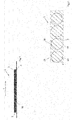
- the stamped part strip 1 shown has stamped parts 2 arranged in a row and spaced apart from one another.
- the distance between the stamped parts 2 depends on the respective application; it can be 1 mm, 2 mm, 3 mm to 6 mm or 7 mm. All intermediate values are also disclosed.
- the stamped parts 2 are arranged along a longitudinal direction L in the stamped part band.
- the stamped part tape 1 comprises a backing layer 3 and an adhesive layer 4.
- the backing layer 3 consists of common plastics, for example, but not by way of limitation: Polyethylene, polypropylene - in particular oriented polypropylene (OPP), cyclic olefin copolymers (COC), polyvinyl chloride (PVC), polyester - in particular polyethylene terephthalate (PET) and polyethylene naphthalate (PEN), ethylene vinyl alcohol (EVOH), polyvinylidene chloride (PVDC), polyvinylidene fluoride (PVDF), polyacrylonitrile (PAN), polycarbonate (PC), polyamide (PA), polyether sulfone (PES) or polyimide (PI).
- Polyethylene polypropylene - in particular oriented polypropylene (OPP), cyclic olefin copolymers (COC), polyvinyl chloride (PVC), polyester - in particular polyethylene terephthalate (PET) and polyethylene
- the adhesive layer 4 consists of a conventional pressure sensitive adhesive.
- the PSA comprises a base and a crosslinkable component, also referred to as a reactive resin.
- Nonpolar elastomers such as vinylaromatic block copolymers
- nonpolar solvents ie in solvents and / or solvent mixtures whose polarity corresponds to ethyl acetate or which are more nonpolar.
- solvents and / or solvent mixtures with a dielectric constant of less than 6.1 [http://en.wikipedia.org/wiki/Solvent] and / or with Hansen parameters ⁇ P Polar ⁇ 5.3; ⁇ H hydrogen bonding ⁇ 7.2 [ Abbott, Steven and Hansen, Charles M. (2008) Hansen Solubility Parameters in Practice, ISBN 0-9551220-2-3 or Hansen, Charles M. (2007) Hansen solubility parameters: a user's handbook CRC Press, ISBN 0-8493-7248-8 ].
- block copolymers are used as elastomers, then they contain at least one block type with a softening temperature of greater than 40 ° C such as vinyl aromatics (also partially or fully hydrogenated variants), methyl methacrylate, cyclohexyl methacrylate, isobornyl methacrylate and isobornyl acrylate.
- the block copolymer contains a block type with a softening temperature of less than -20 ° C.
- polymer blocks having low softening temperatures are polyethers such as polyethylene glycol, polypropylene glycol or polytetrahydrofuran, polydienes, such as polybutadiene or polyisoprene, (partially) hydrogenated polydienes, such as polyethylenebutylene, polyethylene propylene or Polybutylenbutadien, polybutylene, polyisobutylene, polyalkyl vinyl ethers, Polymer blocks ⁇ , ⁇ -unsaturated esters such as, in particular, acrylate copolymers.
- the soft block has a non-polar design and then preferably contains butylene or isobutylene or hydrogenated polydienes as a homopolymer block or copolymer block, the latter preferably copolymerized with itself or with one another or with further, particularly preferably non-polar comonomers.
- suitable nonpolar comonomers are (partially) hydrogenated polybutadiene, (partially) hydrogenated polyisoprene and / or polyolefins.
- the crosslinkable component also referred to as reactive resin, consists of a cyclic ether and is suitable for radiation-chemical and optionally thermal crosslinking with a softening temperature of less than 40 ° C., preferably less than 20 ° C.
- the reactive resins based on cyclic ethers are in particular epoxides, that is to say compounds which carry at least one oxirane group, or oxetanes. They can be aromatic or, in particular, aliphatic or cycloaliphatic in nature.
- Reactive resins that can be used can be monofunctional, difunctional, trifunctional, tetrafunctional or more highly functional up to polyfunctional, the functionality relating to the cyclic ether group.
- Examples are 3,4-epoxycyclohexylmethyl-3 ', 4'-epoxycyclohexanecarboxylate (EEC) and derivatives, dicyclopentadiene dioxide and derivatives, 3-ethyl-3-oxetanmethanol and derivatives, tetrahydrophthalic acid diglycidyl ester and derivatives, and hexahydlycidyl derivatives 1,2-ethanediglycidyl ether and derivatives, 1,3-propanediglycidyl ether and derivatives, 1,4-butanediol diglycidyl ether and derivatives, higher 1, n-alkanediglycidyl ether and derivatives, bis - [(3,4-epoxycyclohexyl) methyl] adipate and derivatives, Vinylcyclohexyl dioxide and derivatives, 1,4-cyclohexanedimethanol bis (3,4-epoxycyclohexane
- Reactive resins can be used in their monomeric or also dimeric, trimeric, etc. up to their oligomeric form.
- the adhesive layer 4 is applied over the entire surface to one side of the backing layer 3.
- the adhesive layer 4 is covered over the entire area with a liner 16.
- the liner 16 sticks the free one Adhesive side of the adhesive layer 4, so that this u. ⁇ . is protected.
- winding the stamped part tape 1 into a stamped part roll 7 and subsequent unwinding are facilitated.
- the stamped parts 2 are in accordance with Fig. 2 punched through the backing 3 and the adhesive layer 4 in their outer contour except for predetermined breaking points 18.
- the predetermined breaking points 18 can be present both in the backing layer 3 and in the adhesive layer 4.
- the target book positions 18 can be perpendicular to the longitudinal direction L laterally on the stamped parts as in Fig. 2 be arranged or in the longitudinal direction L at the front and rear of the stamped parts 2 or both or in another way.
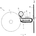
- the stamping tape 1 according to Fig. 1 is first on the stamped part roll 7 according to Fig. 3 wound.
- One end of the punched tape 1 is released from the punched roll 7 and according to Fig. 3 around a stamp head 8 of a stamp 9.
- the stamped part roll 7 is attached to a pin, not shown, and rotatably mounted on it.
- Fig. 3 only shows the basic structure of an applicator 10 according to the invention in a first embodiment.
- the applicator 10 in the first embodiment is suitable for stamped part strips 1 with a liner 16.
- the applicator 10 has a second take-up roll 17, which is arranged on a feed side of the stamp head 8, while a first take-up roll 13 is arranged on the discharge side of the stamp head 8.
- the second winding roll 17 first rolls up the liner 16 on the feed side of the stamping head 8, so that the layer of adhesive 4 of the stamped parts 2 is exposed and then according to Fig. 3 the stamped part tape 1 freed from the liner 16 can be guided around the stamp head 8.
- the stamped part tape 1 To guide the stamped part tape 1 are also deflection rollers u. ⁇ . provided that in the Fig. 2 are not shown.
- the stamped part tape 1, starting from the stamped part roll 7, is guided around the stamp 9 and in particular around the stamp head 8.
- the applicator 10 can be moved back and forth in the application by the flange-mounted robot arm of a robot.
- the surface is in Fig. 2 shown with an opening 12.
- the applicator 10 according to the invention is intended to glue one of the stamped parts 2 onto the opening 12 and thereby to close the opening 12.
- the openings 12 usually have a circular or oval opening cross section with a diameter of approximately 20 mm.
- the stamped parts 2 therefore have a circular diameter of about 30 mm, so that a 5 mm wide adhesive edge, the opening 12 rotating, is formed.
- the feed of the stamped part tape 1 is made available by the driven first winding roll 13.
- the first take-up reel 13 only winds up a holding belt 6 after the stamped parts 2 have been glued in sequence, that is to say without the stamped parts 2.
- a controller is provided which rotates the first winding roll 13 in a clocked manner at an angle which corresponds to the spacing of the stamped parts 2 from one another, so that exactly one of the stamped parts 2 is positioned on the stamp head 8 for each bonding process.
- the stamped part 2 In a stick position, which in Fig. 2 is shown, the stamped part 2 is arranged on the stamp head 8. In this state, it can be glued onto the opening 12 by moving the applicator 10 toward it.
- the applicator 10 is controlled as follows: a first sensor is provided which is directed towards the stamp head 8 and which registers the presence of the stamped part 2 on the stamp head 8. This can e.g. by means of a colored tax marking, but other registration options are also conceivable. If the stamped part 2 is present, the first sensor emits a signal to the control unit, which emits a stop signal to a drive of the first winding roll 13. The rotation of the first take-up roll 13 is stopped. The applicator 10 is pressed onto the opening 12 by a flange-mounted robot arm and thus the stamped part 2.
- the applicator 10 is then raised again and coordinated by the control, the first take-up roll 13 is rotated somewhat, so that the stamped part tape 1 does not hang loosely above the retracted stamp head 8. As a result, the stamped part 2 tears off from a stamped part complement 19 at the predetermined breaking points 18.
- the first winding roll 13 is then rotated further so that the next stamped part 2 is positioned on the retracted stamp head 8.
- the entire applicator 10 is moved from a position above that in FIG Fig. 2 Move opening 12 shown into a next position, in which the stamp head 8 is positioned over the next opening 12.
- Either a second sensor can be provided which registers the next opening 12 and emits a signal to the control which stops the drive so that the applicator 10 remains in the next position above the surface 11, or it is provided that in the control of the robot arm, the opening pattern of the surface 11 is stored, so that the applicator 10 moves to the openings 12 one after the other.
- the stamp head 8 has a pressure surface which is identical to the outer contour of the stamped part 2, so that only the stamped part 2 is glued to the surface 11. Due to the movement of the punch head 8, the predetermined breaking points 18 tear open because the adhesive force of the stamped part 2 on the surface 11 is greater than the tensile strength of the predetermined breaking points 18 of the stamped part 2. After the stamped part 2 has been torn out, a perforated tape 20 remains as the stamped part complement 19, that is wound on the first unwinding roll 13.
- the carrier layer 3 projects beyond the stamped part 2 laterally, perpendicular to the longitudinal direction L, by a width d that is dimensioned such that the stamped part strip 1 can be pulled off the stamped part roll 7 by tensile force at the end of the perforated strip 20 without tearing.
- the liner 16 is wound on the second winding roll 17 and the perforated tape 20 is wound on the first winding roll 13, and the liner 16 and the perforated belt 20 can be recycled.
- Fig. 5 shows a basic side view of an applicator 10 according to the invention in a second embodiment.
- the second embodiment of the applicator 10 is intended to apply stamped parts 2 from a stamped part strip 1 which has no liner 16.
- the applicator 10 has the stamped part roll 7, which, however, is different from the stamped part roll 7 in the first embodiment Fig. 3 the other way around, in Fig. 5 clockwise.
- the stamped part strip 1 is wound on the stamped part roll 7, the stamped part strip 1 has a carrier layer 3, and stamped parts 2 arranged at a distance from one another in the longitudinal direction L along the carrier layer 3.
- the stamped parts 2 have an adhesive layer 4 on their side facing away from the carrier layer 3.
- the adhesive layer 4 is not covered by a liner 16, but is exposed and the stamped part tape is wound up with the exposed adhesive layer to form the stamped part roll 7.
- the adhesive strength of the adhesive layer 4 is dimensioned such that problem-free unwinding of the stamped part strip 1 from the stamped part roll 7 is possible by pulling on the free end of the stamped part strip 1.
- the free end of the stamped part tape 1 is guided around the stamp head 8 as in the first embodiment.
- the second winding roll 17 for winding the liner 16 is no longer necessary in the second embodiment of the applicator 10.
- the function of the applicator 10 with regard to the application of the stamped part 2 to the opening 12 is the same as that of the applicator 10 of the first embodiment.
- the disclosure of the previous figures also applies accordingly to Fig.
- the stamped part strip 1 is pulled on the carrier layer 3 by driven rotation of the first winding roll 13, and the stamped part strip 1 is positioned over the opening 12 such that a stamped part 2 is positioned exactly on the carrier head 8.
- the applicator 10 is then pressed onto the opening 12 in a movement of the robot arm (not shown) on which the applicator 10 is arranged and through the adhesive force of the adhesive layer 4 of the stamped part 2 along the opening edge tears the stamped part 2 out of the stamped part strip 1 when the applicator 10 moves away from the surface 11.
- the perforated tape 20 that is formed is wound on the first winding roll 13.
- the perforated tape 20 on the first take-up reel has the same shape as the perforated tape 20 on the first take-up roll 13 of the first embodiment.
Landscapes
- Engineering & Computer Science (AREA)
- General Engineering & Computer Science (AREA)
- Physics & Mathematics (AREA)
- Fluid Mechanics (AREA)
- Textile Engineering (AREA)
- Mechanical Engineering (AREA)
- Adhesive Tapes (AREA)
- Making Paper Articles (AREA)
- Adhesive Tape Dispensing Devices (AREA)
Abstract
Description
- Die Erfindung betrifft einen Applikator für Stanzteile mit einem Stanzteilband mit einer Träger- und einer Klebmasseschicht. Die Erfindung betrifft auch ein Verfahren zum Aufbringen von Stanzteilen auf eine Oberfläche. Die Erfindung betrifft auch ein Stanzteilband mit einer Trägerschicht und einer Klebmasseschicht.
- Bei der Herstellung von Kraftfahrzeugen entsteht häufig das Problem, dass in Karosserieteilen eingebrachte Öffnungen nach Bearbeitungsvorgängen wieder verklebt werden müssen. Beispielsweise können Karosserieteile mit Flüssigkeit oberflächenbehandelt werden. Die zur Oberflächenbehandlung erforderliche Flüssigkeit läuft über in die Karosserieteile vorher eingebrachte Öffnungen von selbst ab. Nachträglich werden die Öffnungen wieder verschlossen. Das Verschließen der Öffnungen erfolgt häufig per Hand, indem Stanzteile von einem Stanzteilband oder einem Stanzteilblatt abgenommen und per Hand auf die Öffnungen aufgeklebt werden. Die Stanzteile weisen eine Trägerschicht auf und eine auf der einen Seite der Trägerschicht aufgebrachte Klebmasseschicht. Die Klebmasseschicht ist in der Regel vollflächig auf die Trägerschicht aufgebracht.
- Im Stand der Technik sind darüber hinaus Roboterarme bekannt.
- Dazu wird eine Stanzteilrolle, auf der ein Stanzteilband in herkömmlicher Weise aufgewickelt ist, zur Verfügung gestellt. Bei dem Stanzteilband handelt es sich in der Regel um einen Liner, der bandförmig vorliegt. Auf diesen Liner sind der Reihe nach voneinander beabstandet Stanzteile mit Trägerschicht und Klebmasseschicht derart aufgebracht, dass die freie Seite der Klebmasseschicht auf dem Liner aufgeklebt ist, so dass die dem Liner gegenüberliegende Seite der Klebmasseschicht von der Trägerschicht abgedeckt ist, so dass die Klebmasse vollständig geschützt ist. Das Stanzteilband kann dann aufgewickelt werden, und zwar so, dass der Liner wicklungsaußenseitig und die Stanzteile wicklungsinnenseitig auf einer Stanzteilrolle angeordnet sind. Bekannterweise wird das freie Ende des Stanzteilbandes abgezogen und in einer Vorrichtung eingespannt, und ein Roboterarm saugt die Stanzteile nacheinander vom Stanzteilband ab. Dazu ist der Roboterarm rüsselartig ausgebildet und saugt das Stanzteil an der Trägerschicht an, löst es von dem Liner ab und drückt das Stanzteil auf die Öffnung in der vorgegebenen Position.
- Nachteiligerweise ist dieses Verfahren relativ zeitaufwendig, da der Roboterarm nach jedem Klebevorgang wieder zur Stanzteilrolle zurückbewegt werden muss, um das nächste Stanzteil vom Stanzteilband abzulösen.
- Darüber hinaus sind Applikatoren in Form von Etikettenspendern bekannt. Dabei ist der Etikettenspender an einem Roboterarm angeordnet. Der Etikettenspender weist die Stanzteilrolle auf. Die Stanzteilrolle wird zu einer Andruckwalze geführt und der Liner automatisch abgezogen und das Stanzteil durch Verfahren des Etikettenspenders mithilfe der Andruckwalze auf das Loch aufgedrückt. Nachteiligerweise ist dieses Verfahren ziemlich platzaufwendig, da der Etikettenspender mithilfe des Roboterarms über eine gewisse Strecke gezogen werden muss. Das z. B. ist nachteilig in schlecht zugänglichen Bereichen eines Autoblechs, beispielsweise, wenn die zu verschließende Öffnung direkt neben einer hochgebogenen Kante platziert ist.
- Es ist daher in einem ersten Aspekt Aufgabe der vorliegenden Erfindung, einen Applikator zur Verfügung zu stellen, der die oben genannten Nachteile verringert.
- Es ist in einem zweiten Aspekt Aufgabe der Erfindung, ein Verfahren zur Verfügung zu stellen, mit dem Stanzteile aufgeklebt werden können und die oben genannten Nachteile vermieden werden.
- Es ist in einem dritten Aspekt auch Aufgabe der Erfindung, ein Stanzteilband zur Verfügung zu stellen, mit dem das oben genannte Verfahren durchführbar ist.
- Hinsichtlich des Applikators wird die Aufgabe durch einen eingangs genannten Applikator mit den Merkmalen des Anspruchs 1 gelöst.
- Der erfindungsgemäße Applikator für Stanzteile umfasst ein Stanzteilband mit einer Längsrichtung und vorzugsweise entlang der Längsrichtung voneinander beabstandet aufgebrachten Stanzteilen. Das Stanzteilband weist eine Träger- und eine Klebmasseschicht auf, wobei eine Außenkontur der Stanzteile durch die Träger- und die Klebmasseschicht bis auf Sollbruchstellen durchgestanzt ist. Vorzugsweise befinden sich die Sollbruchstellen in der Trägerschicht, besonders bevorzugt nur in der Trägerschicht.
- Erfindungsgemäß überragt ein Stanzteilkomplement die Stanzteile durchgehend seitlich also senkrecht zur Längsrichtung. Das Stanzteilkomplement bildet nach dem Herauslösen der Stanzteile ein Lochband aus, das an den seitlich überragenden Abschnitten zusammengehalten wird. Die Abschnitte sind breit genug gewählt, so dass sie hinreichend reißfest sind, um durch Ziehen an einem Ende des Lochbandes ein Abwickeln des Stanzteilbandes von einer Stanzteilbandrolle zu ermöglichen.
- Der erfindungsgemäße Applikator umfasst einen Stempel mit einem Stempelkopf, über den das Stanzteilband läuft, wobei das über den Stempelkopf laufende Stanzteilband mit seiner Klebmasseschicht dem Stempelkopf abgewandt angeordnet ist. Die erfindungsgemäßen Stanzteile sind daher gegenüber dem Stand der Technik gleichsam um die Längsrichtung um 180° gedreht angeordnet. Dadurch ist es möglich, dass die Stanzteile mittels eines Stempels auf eine Oberfläche aufdrückbar sind und durch Aufreißen der Sollbruchstellen herauslösbar sind. Durch Weiterbefördern des Stanzteilbandes bzw. Lochbandes wird das nächste Stanzteil in die Position des Stempels gebracht.
- Vorzugsweise ist eine Steuerung vorgesehen. Die Steuerung umfasst einen ersten Sensor, der mit einem Abtastbereich auf den Stempelkopf gerichtet ist und das Vorhandensein eines Stanzteils am Stempelkopf registriert. Dieses kann z.B. durch eine farbliche Steuermarkierung erfolgen, es sind aber auch andere Erfassungsmöglichkeiten denkbar. Die Steuerung ist mit dem Sensor signalleitend verbunden, und Messwerte des Sensors werden der Steuerung zugeführt. Der Applikator ist gemäß einer besonders bevorzugten Variante an einem frei beweglichen Roboterarm befestigt. Der Roboterarm steuert zum einen eine Hin-und-her-Bewegung des Applikators in der z-Richtung senkrecht zur Oberfläche und zum anderen eine Bewegung in einer xy-Ebene parallel zur Oberfläche. Der Roboterarm ist in der Lage, entsprechend auf die Steuerungssignale zu reagieren.
- Des Weiteren wird der getaktete Vortrieb des Stanzteilbandes gesteuert, mit dem das nachfolgende Stanzteil auf dem Stempelkopf positioniert werden kann. Der Vortrieb des Stanzteilbandes kann als angetriebene erste Aufwickelrolle für das Lochband ausgebildet sein.
- Wenn der erste Sensor das Vorhandensein eines Stanzteils am Stempelkopf signalisiert und einen entsprechenden Messwert an die Steuerung leitet, wird der Vortrieb des Stanzteilbandes gestoppt und dem Roboter ein Signal zugeführt, und der Roboter bewegt den Applikator samt Stempelkopf in einer Hin-Bewegung auf die Oberfläche zu und in einer Her-Bewegung von der Oberfläche zurück. Die Hin-Bewegung erfolgt dabei so weit, bis das Stanzteil auf der Oberfläche aufklebt. Dafür kann ein entsprechender Drucksensor am Stempel angeordnet sein, der den Druckwiderstand durch die Oberfläche registriert. Der Stempelkopf und das Stanzteil sind dabei in ihrer Außenkontur vorzugsweise identisch, so dass tatsächlich nur oder vorwiegend das Stanzteil und nicht das Stanzteilkomplement auf die Oberfläche gedrückt wird und dort eine Haftklebverbindung herstellt.
- Durch die Her-Bewegung des Stempelkopfes und/oder eine Weiterbeförderung des Stanzteilbandes brechen die Sollbruchstellen auf, und das Stanzteil löst sich aus dem Stanzteilband und hinterlässt als Stanzteilkomplement das Lochband.
- Damit der Applikator von der ersten Position zur nächsten Position verbracht wird, ist der Steuerung vorzugsweise ein Öffnungsmuster oder Klebemuster in der Robotersteuerung einprogrammiert. Die Steuerung kann dazu als NC-Steuerung ausgebildet sein. Es ist auch denkbar, dass ein zweiter Sensor vorgesehen ist, der die Löcher beim Überfahren der Oberfläche registriert. Es kann auch eine Kombination aus NC-Steuerung und Sensorik vorgesehen sein.
- Günstigerweise steuert die Steuerung den Roboter an, der den Applikator samt Stempelkopf in eine erste Position über der Oberfläche bewegt und das Stanzteil an einer ersten Oberflächenposition aufklebt. Sie steuert nach dem Aufkleben des Stanzteils den Roboter wiederum an und bewegt den Applikator samt Stempelkopf in der xy-Ebene in eine zweite Position über der Oberfläche; dort wird das nächste Stanzteil durch eine Hin-Bewegung in z-Richtung auf die nächste Öffnung aufgeklebt.
- Günstigerweise ist eine Stanzteilrolle auf einer Zuführseite des Stempelkopfes und eine erste Aufwickelrolle auf einer Abführseite des Stempelkopfes vorgesehen. Die erste Aufwickelrolle ist mit der Steuerung signalleitend verbunden, und auf ihr ist das Lochband aufwickelbar. Die Steuerung dreht die erste Aufwickelrolle getaktet. Dabei entspricht der Vorschub eines Taktes jeweils dem Abstand benachbarter Stanzteile in dem Stanzteilband.
- In einer weiteren bevorzugten Ausführungsform der Erfindung ist eine zweite Aufwickelrolle an der Zuführseite zum Aufwickeln eines Liners vorgesehen. Die freie Klebseite des Stanzteilbandes kann optional mit einem Liner abgedeckt sein. Der Liner ist dann auf der zweiten Aufwickelrolle auf der Zuführseite, bevor das Stanzteil dem Stempelkopf zugeführt wird, abzuziehen.
- Die Aufgabe wird auch durch ein oben genanntes Verfahren mit den Merkmalen des Anspruchs 6 gelöst.
- Das Verfahren eignet sich zur Durchführung mit einem der oben genannten Applikatoren; umgekehrt eignen sich die Applikatoren auch zur Durchführung einer der folgenden Verfahren. Erfindungsgemäß läuft ein Stanzteilband mit einer Längsrichtung und mit einer Trägerschicht und einer Klebmasseschicht über einen Stempelkopf eines Stempels, wobei eine Außenkontur der Stanzteile durch die Träger- und Klebmasseschicht bis auf Sollbruchstellen durchgestanzt ist und ein Stanzteilkomplement die Stanzteile durchgehend seitlich zur Längsrichtung überragt.
- Erfindungsgemäß wird das Stanzteilband gestoppt, wenn ein Stanzteil über dem Stempelkopf positioniert ist, und der Stempel wird dann in einer Hin-Bewegung mittels eines Roboterarms auf der Oberfläche bewegt und das Stanzteil auf die Oberfläche geklebt. Während der Hin-Bewegung wird das Stanzteilband etwas nachgeführt, damit das Stanzteil nicht vom Stempelkopf rutscht. Eine Andruckfläche oder zumindest Außenkontur des Stempelkopfes ist dem Stanzteil identisch.
- Ebenso wird das Stanzteilband während der Her-Bewegung ebenfalls durch Nachführen des Stanzteilbandes gespannt gehalten. Durch die Her-Bewegung werden die Sollbruchstellen aufgebrochen. Es ist auch denkbar, dass das Stanzteilband zunächst oder gleichzeitig etwas vorbefördert wird und dadurch die Sollbruchstellen aufbrechen. Eine Klebkraft der Klebmasseschicht auf der Oberfläche und eine Reißfestigkeit der Sollbruchstellen sind entsprechend aufeinander abgestimmt.
- Das erfindungsgemäße Verfahren ermöglicht es in einfacher Weise, Stanzteile auf einer Oberfläche, insbesondere auf Öffnungen, zu positionieren, wobei das Stanzteil natürlich im Durchmesser etwas größer als die Öffnung gewählt wird, damit ein Kleberand entsteht. Natürlich können die Stanzteile aber auch auf andere Positionen als auf Öffnungen geklebt werden.
- Aufgrund der Hin-und-her-Bewegung des Stempelkopfes in der z-Richtung wird nur sehr wenig Platz in der xy-Ebene benötigt, um ein Stanzteil auf einer Oberfläche aufzubringen. Dies ist ein Vorteil gegenüber den bekannten Etikettenspendern.
- Darüber hinaus ist es vorzugsweise möglich, dass eine erste Position auf der Oberfläche bestimmt wird, das Stanzteil auf die erste Position geklebt wird und dass eine zweite Position bestimmt wird und der Stempel bereits während der Weitertaktung des Stanzteilbandes zur zweiten Position bewegt wird. Vorzugsweise ist das nächste Stanzteil bereits wieder auf dem Stanzteilkopf angeordnet, wenn der Stempel seine vorgesehene zweite Position erreicht hat. Dieses ist gegenüber dem bekannten Roboterarm eine erhebliche Zeitersparnis. Vorzugsweise kann ein erster Sensor auf den Stempelkopf gerichtet werden und das Vorhandensein des Stanzteils erkennen. Beim Erkennen des Stanzteils wird das Stanzteilband gestoppt, und wenn der Stempel seine Position über der Oberfläche erreicht hat, wird der Stempel zur Oberfläche bewegt, das Stanzteil aufgeklebt und das Stanzteilband um ein Stanzteil weitergetaktet. Der Roboterarm ist zum Verfahren des Applikators in der xy-Ebene parallel zur Oberfläche ausgebildet, während die Hin-und-her-Bewegung des Stempels in z-Richtung erfolgt.
- Die Steuerung steuert auch die Geschwindigkeit und den Drehwinkel einer Aufwickelrolle, auf der das Lochband aufgewickelt wird, sowie gegebenenfalls die Geschwindigkeit und den Drehwinkel einer zweiten Aufwickelrolle, auf der ein optionaler Liner aufgewickelt werden kann.
- Die Erfindung wird in ihrem dritten Aspekt durch ein Stanzteilband mit den Merkmalen des Anspruchs 10 gelöst.
- Das erfindungsgemäße Stanzteilband weist eine Längsrichtung auf und eine Trägerschicht und eine Klebmasseschicht, wobei eine Außenkontur der Stanzteile durch die Träger- und Klebmasseschicht bis auf Sollbruchstellen durchgestanzt ist und ein Stanzteilkomplement die Stanzteile durchgehend seitlich zur Längsrichtung überragt. Das Stanzteilkomplement ist ein durchgehendes Lochband. Vorzugsweise ist die Klebmasseschicht entlang der Außenkontur des Stanzteils vollständig durchgestanzt, und die Soll-Bruchstellen sind nur in der Trägerschicht vorhanden. Das Stanzteilband ist dann durch Ziehen an der Trägerschicht abrollbar und beförderbar.
- Die Stanzteile sind gegenüber den bekannten Stanzteilbändern gleichsam um 180° um die Längsrichtung gedreht angeordnet. Die Klebmasseschicht liegt frei und kann durch Druck auf das Stanzteil auf eine Oberfläche aufgeklebt und das Stanzteilkomplement dann von dem Stanzteil abgelöst werden, indem die Sollbruchstellen aufbrechen. Dafür ist die Trennkraft zwischen der Klebmasseschicht und der zu beklebenden Oberfläche vorzugsweise größer gewählt als die Reißfestigkeit der das Stanzteil haltenden Sollbruchstellen.
- In einer weiteren Ausführungsform des erfindungsgemäßen Stanzteilbandes ist ein Liner vorgesehen, der entlang der Klebmasseschicht angeordnet ist und die freien Seiten der Klebmasseschichten der Stanzteile abdeckt. Das Stanzteilband kann mit der Trägerschicht der Klebmasseschicht und dem Liner zur Stanzteilrolle aufgewickelt werden. In beiden Ausführungsformen des Stanzteilbandes ist das aufgewickelte Stanzteilband mit der Trägerschicht wicklungsinnenseitig und mit der Klebmasseschicht wicklungsaußenseitig aufgewickelt.
- Die Erfindung wird anhand von zwei Ausführungsbeispielen in vier Figuren beschrieben. Dabei zeigen:
- Fig. 1
- eine prinzipielle Seitenansicht eines erfindungsgemäßen Stanzteilbandes,
- Fig. 2
- eine prinzipielle Draufsicht des Stanzteilbandes in
Fig. 1 , - Fig. 3
- eine prinzipielle Seitenansicht eines erfindungsgemäßen Applikators für das Stanzteilband in einer ersten Ausführungsform,
- Fig. 4
- eine prinzipielle Draufsicht des Stanzteilbandes nach Herausreißen von Stanzteilen,
- Fig. 5
- eine prinzipielle Seitenansicht eines erfindungsgemäßen Applikators für das Stanzteilband in einer zweiten Ausführungsform
- Ein in der
Fig. 1 dargestelltes Stanzteilband 1 weist in einer Reihe angeordnete Stanzteile 2 auf, die voneinander beabstandet sind. Der Abstand der Stanzteile 2 voneinander richtet sich nach der jeweiligen Applikation; er kann 1 mm, 2 mm, 3 mm bis 6 mm oder 7 mm betragen. Es sind auch alle Zwischenwerte mitoffenbart. Die Stanzteile 2 sind entlang einer Längsrichtung L in dem Stanzteilband angeordnet. - Das Stanzteilband 1 umfasst eine Trägerschicht 3 und eine Klebmasseschicht 4. Die Trägerschicht 3 besteht aus gängigen Kunststoffen, beispielhaft, aber nicht einschränkend erwähnt seien:
Polyethylen, Polypropylen - insbesondere das durch mono- oder biaxiale Streckung erzeugte orientierte Polypropylen (OPP), cyclische Olefin Copolymere (COC), Polyvinylchlorid (PVC), Polyester - insbesondere Polyethylenterephthalat (PET) und Poylethylennaphthalat (PEN), Ethylenvinylalkohol (EVOH), Polyvinylidenchlorid (PVDC), Polyvinylidenfluorid (PVDF), Polyacrylnitril (PAN), Polycarbonat (PC), Polyamid (PA), Polyethersulfon (PES) oder Polyimid (PI). - Die Klebmasseschicht 4 besteht aus einer üblichen Haftklebmasse. Die Haftklebmasse umfasst eine Basis und eine vernetzbare Komponente, auch als Reaktivharz bezeichnet.
- Als Basis für Haftklebmassen kommen verschiedene Materialien, insbesondere unpolare Elastomere in Frage.
- Unpolare Elastomere, wie beispielsweise Vinylaromaten-Blockcopolymere, zeichnen sich dadurch aus, dass sie in unpolaren Lösungsmitteln gelöst werden können, d. h. in Lösungsmitteln und/oder Lösungsmittelgemischen, deren Polarität Ethylacetat entspricht oder die unpolarer sind. Dies sind insbesondere Lösungsmittel und/oder Lösungsmittelgemische mit einer Dielektrizitätskonstante von kleiner 6.1 [http://en.wikipedia.org/wiki/Solvent] und/oder mit Hansenparametern δP Polar ≤ 5.3; δH Hydrogen bonding ≤ 7.2 [Abbott, Steven and Hansen, Charles M. (2008) Hansen Solubility Parameters in Practice, ISBN 0-9551220-2-3 oder Hansen, Charles M. (2007) Hansen solubility parameters: a user's handbook CRC Press, ISBN 0-8493-7248-8].
- Kommen als Elastomere Blockcopolymere zum Einsatz, dann enthalten diese zumindest eine Blocksorte mit einer Erweichungstemperatur von größer 40 °C wie zum Beispiel Vinylaromate (auch teil- oder vollhydrierte Varianten), Methylmethacrylat, Cyclohexylmethacrylat, Isobornylmethacrylat und Isobornylacrylat.
- Weiter vorzugsweise enthält das Blockcopolymer eine Blocksorte mit einer Erweichungstemperatur von kleiner - 20 °C.
- Beispiele für Polymerblöcke mit niedrigen Erweichungstemperaturen ("Weichblöcke") sind Polyether wie zum Beispiel Polyethylenglykol, Polypropylenglykol oder Polytetrahydrofuran, Polydiene wie zum Beispiel Polybutadien oder Polyisopren, (teil)hydrierte Polydiene wie zum Beispiel Polyethylenbutylen, Polyethylenpropylen oder Polybutylenbutadien, Polybutylen, Polyisobutylen, Polyalkylvinylether, Polymerblöcke α,β-ungesättigter Ester wie insbesondere Acrylat-Copolymere.
- Der Weichblock ist dabei in einer Auslegung unpolar aufgebaut und enthält dann bevorzugt Butylen oder Isobutylen oder hydrierte Polydiene als Homopolymerblock oder Copolymerblock, letztere vorzugsweise mit sich selbst oder miteinander oder mit weiteren, besonders bevorzugt unpolaren Comonomeren copolymerisiert. Als unpolare Comonomere sind beispielsweise (teil-)hydriertes Polybutadien, (teil-)hydriertes Polyisopren und/oder Polyolefine geeignet.
- Die vernetzbare Komponente, auch als Reaktivharz bezeichnet, besteht aus einem cyclischen Ether und eignet sich für die strahlenchemische und gegebenenfalls thermische Vernetzung mit einer Erweichungstemperatur von kleiner 40 °C, bevorzugt von kleiner 20 °C.
- Bei den Reaktivharzen auf Basis cyclischer Ether handelt es sich insbesondere um Epoxide, also Verbindungen, die zumindest eine Oxiran-Gruppe tragen, oder Oxetane. Sie können aromatischer oder insbesondere aliphatischer oder cycloaliphatischer Natur sein.
- Einsetzbare Reaktivharze können monofunktionell, difunktionell, trifunktionell, tetrafunktionell oder höher funktionell bis zu polyfunktionell gestaltet sein, wobei sich die Funktionalität auf die cyclische Ethergruppe bezieht.
- Beispiele, ohne sich einschränken zu wollen, sind 3,4-Epoxycyclohexylmethyl-3',4'-epoxycyclohexancarboxylat (EEC) und Derivate, Dicyclopentadiendioxid und Derivate, 3-Ethyl-3-oxetanmethanol und Derivate, Tetrahydrophthalsäurediglycidylester und Derivate, Hexahydrophthalsäurediglycidylester und Derivate, 1,2-Ethandiglycidylether und Derivate, 1,3-Propandiglycidylether und Derivate, 1,4-Butandioldiglycidylether und Derivate, höhere 1,n-Alkandiglycidylether und Derivate, Bis-[(3,4-epoxycyclohexyl)methyl]-adipat und Derivate, Vinylcyclohexyldioxid und Derivate, 1,4-Cyclohexandimethanol-bis-(3,4-epoxycyclohexancarboxylat) und Derivate, 4,5-Epoxytetrahydrophthalsäurediglycidylester und Derivate, Bis-[1-ethyl(3-oxetanyl)methyl]ether und Derivate, Pentaerythritoltetraglycidylether und Derivate, Bisphenol-A-Digylcidylether (DGEBA), hydriertes Bisphenol-A-Diglycidylether, Bisphenol-F-Diglycidylether, hydriertes Bisphenol-F-Diglycidylether, Epoxyphenol-Novolaks, hydrierte Epoxyphenol-Novolaks, Epoxycresol-Novolaks, hydrierte Epoxycresol-Novolaks, 2-(7-Oxabicyclo)Spiro[1,3-dioxane-5,3'-[7]oxabicyclo[4.1.0]-heptane], 1,4-Bis((2,3-epoxypropoxy)methyl)cyclohexane.
- Reaktivharze können in ihrer monomeren oder auch dimeren, trimeren, usw. bis hin zu ihrer oligomeren Form eingesetzt werden.
- Gemische von Reaktivharzen untereinander, aber auch mit anderen coreaktiven Verbindungen wie Alkoholen (monofunktionell oder mehrfach funktionell) oder Vinylethern (monofunktionell oder mehrfach funktionell), sind ebenfalls möglich.
- Die Klebmasseschicht 4 ist vollflächig auf die eine Seite der Trägerschicht 3 aufgebracht. Die Klebmasseschicht 4 ist vollflächig mit einem Liner 16 abgedeckt. Der Liner 16 klebt die freie Klebseite der Klebmasseschicht 4 ab, so dass diese vor Verunreinigungen u. Ä. geschützt ist. Darüber hinaus werden ein Aufwickeln des Stanzteilbandes 1 zu einer Stanzteilrolle 7 und ein nachträgliches Abwickeln erleichtert.
- Die Stanzteile 2 sind gemäß
Fig. 2 in ihrer Außenkontur bis auf Sollbruchstellen 18 durch die Trägerschicht 3 und die Klebmasseschicht 4 durchgestanzt. Die Sollbruchstellen 18 können sowohl in der Trägerschicht 3 als auch in der Klebmasseschicht 4 vorhanden sein. Die Sollbuchstellen 18 können senkrecht zur Längsrichtung L seitlich an den Stanzteilen wie inFig. 2 angeordnet sein oder auch in Längsrichtung L vorn und hinten an den Stanzteilen 2 oder beides oder auch in anderer Weise. - Das Stanzteilband 1 gemäß
Fig. 1 ist zunächst auf der Stanzteilrolle 7 gemäßFig. 3 aufgewickelt. Ein Ende des Stanzteilbandes 1 wird von der Stanzteilrolle 7 gelöst und gemäßFig. 3 um einen Stempelkopf 8 eines Stempels 9 herumgelegt. Die Stanzteilrolle 7 ist auf einen nicht näher dargestellten Stift aufgesteckt und auf ihm drehbar gelagert.Fig. 3 zeigt lediglich den prinzipiellen Aufbau eines erfindungsgemäßen Applikators 10 in einer ersten Ausführungsform. Der Applikator 10 in der ersten Ausführungsform ist für Stanzteilbänder 1 mit einem Liner 16 geeignet. - Der Applikator 10 weist eine zweite Aufwickelrolle 17 auf, die auf einer Zuführseite des Stempelkopfes 8 angeordnet ist, während eine erste Aufwickelrolle 13 auf der Abführseite des Stempelkopfes 8 angeordnet ist. Die zweite Aufwickelrolle 17 rollt zunächst den Liner 16 auf der Zuführseite des Stempelkopfes 8 auf, so dass die Klebmasseschicht 4 der Stanzteile 2 freiliegt und dann gemäß
Fig. 3 das vom Liner 16 befreite Stanzteilband 1 um den Stempelkopf 8 herumgeführt werden kann. - Zur Führung des Stanzteilbandes 1 sind zusätzlich noch Umlenkrollen u. Ä. vorgesehen, die in der
Fig. 2 nicht eingezeichnet sind. Das Stanzteilband 1 wird, ausgehend von der Stanzteilrolle 7, um den Stempel 9 und insbesondere um den Stempelkopf 8 herumgeführt. Der Applikator 10 ist in der Applikation durch den angeflanschten Roboterarm eines Roboters hin und her beweglich. Die Oberfläche ist inFig. 2 mit einer Öffnung 12 dargestellt. Der erfindungsgemäße Applikator 10 ist dazu vorgesehen, eines der Stanzteile 2 auf die Öffnung 12 zu kleben und die Öffnung 12 damit zu verschließen. - Die Öffnungen 12 weisen üblicherweise einen kreisförmigen oder ovalen Öffnungsquerschnitt mit einem Durchmesser von etwa 20 mm auf. Die Stanzteile 2 haben daher einen kreisförmigen Durchmesser von etwa 30 mm, so dass ein 5 mm breiter Kleberand, die Öffnung 12 umlaufend, ausgebildet wird. Der Vorschub des Stanzteilbandes 1 wird durch die angetriebene erste Aufwickelrolle 13 zur Verfügung gestellt.
- Die erste Aufwickelrolle 13 wickelt nur einen Haltegurt 6, nachdem die Stanzteile 2 der Reihe nach aufgeklebt wurden, auf, also ohne die Stanzteile 2.
- Es ist eine Steuerung vorgesehen, die die erste Aufwickelrolle 13 getaktet in einem Winkel dreht, der dem Abstand der Stanzteile 2 voneinander entspricht, so dass für jeden Klebvorgang genau eines der Stanzteile 2 auf dem Stempelkopf 8 positioniert ist. In einer Klebstellung, die in
Fig. 2 dargestellt ist, ist das Stanzteil 2 auf dem Stempelkopf 8 angeordnet. Er kann in diesem Zustand durch Hin-Bewegung des Applikators 10 auf die Öffnung 12 geklebt werden. - Eine Steuerung des Applikators 10 funktioniert dabei wie folgt: Es ist ein erster Sensor vorgesehen, der auf den Stempelkopf 8 gerichtet ist und der das Vorhandensein des Stanzteils 2 auf dem Stempelkopf 8 registriert. Dieses kann z.B. durch eine farbliche Steuermarkierung erfolgen, es sind aber auch andere Erfassungsmöglichkeiten denkbar. Bei Vorhandensein des Stanzteils 2 gibt der erste Sensor ein Signal an die Steuerung ab, die ein Stoppsignal an einen Antrieb der ersten Aufwickelrolle 13 abgibt. Die Drehbewegung der ersten Aufwickelrolle 13 wird gestoppt. Der Applikator 10 wird durch einen angeflanschten Roboterarm und damit das Stanzteil 2 auf die Öffnung 12 gedrückt. Daraufhin wird der Applikator 10 wieder hochgefahren und durch die Steuerung koordiniert, die erste Aufwickelrolle 13 etwas gedreht, so dass das Stanzteilband 1 nicht lose über dem eingefahrenen Stempelkopf 8 hängt. Dadurch reißt das Stanzteil 2 an den Sollbruchstellen 18 von einem Stanzteilkomplement 19 ab.
- Die erste Aufwickelrolle 13 wird dann weitergedreht, so dass das nächste Stanzteil 2 auf dem eingezogenen Stempelkopf 8 positioniert ist. Während des Weitertransportes des Stanzteilbandes 1 wird durch den Antrieb der gesamte Applikator 10 von einer Position über der in
Fig. 2 dargestellten Öffnung 12 in eine nächste Position verfahren, in der der Stempelkopf 8 über der nächsten Öffnung 12 positioniert ist. Es kann entweder ein zweiter Sensor vorgesehen sein, der die nächste Öffnung 12 registriert und ein Signal an die Steuerung abgibt, die den Antrieb stoppt, so dass der Applikator 10 in der nächsten Position über der Oberfläche 11 stehenbleibt, oder es ist vorgesehen, dass in der Steuerung des Roboterarms das Öffnungsmuster der Oberfläche 11 abgelegt ist, so dass der Applikator 10 nacheinander die Öffnungen 12 anfährt. - Der Stempelkopf 8 weist eine Andrückfläche auf, die mit der Außenkontur des Stanzteils 2 identisch ist, so dass nur das Stanzteil 2 auf die Oberfläche 11 geklebt wird. Durch die Her-Bewegung des Stempelkopfes 8 reißen die Sollbruchstellen 18 auf, weil die Klebkraft des Stanzteils 2 auf der Oberfläche 11 größer ist als die Reißfestigkeit der Sollbruchstellen 18 des Stanzteils 2. Nach dem Herausreißen des Stanzteils 2 verbleibt als Stanzteilkomplement 19 ein Lochband 20, das auf der ersten Auswickelrolle 13 aufgewickelt wird. Die Trägerschicht 3 überragt das Stanzteil 2 seitlich, senkrecht zur Längsrichtung L um eine Breite d, die so bemessen ist, dass durch Zugkraft am Ende des Lochbandes 20 das Stanzteilband 1 von der Stanzteilrolle 7 abgezogen werden kann, ohne zu reißen.
- Der Liner 16 wird auf der zweiten Aufwickelrolle 17 aufgewickelt und das Lochband 20 wird auf der ersten Aufwickelrolle 13 aufgewickelt, und der Liner 16 und das Lochband 20 können einem Recycling zugeführt werden.
-
Fig. 5 zeigt eine prinzipielle seitliche Ansicht eines erfindungsgemäßen Applikators 10 in einer zweiten Ausführungsform. Die zweite Ausführungsform des Applikators 10 ist dazu bestimmt, Stanzteile 2 von einem Stanzteilband 1 zu applizieren, das keinen Liner 16 aufweist. Der Applikator 10 weist die Stanzteilrolle 7 auf, die sich jedoch gegenüber der Stanzteilrolle 7 der ersten Ausführungsform inFig. 3 anders herum, inFig. 5 im Uhrzeigersinn, abwickelt. Auf der Stanzteilrolle 7 ist das Stanzteilband 1 aufgewickelt, dass Stanzteilband 1 weist eine Trägerschicht 3 auf, sowie voneinander beabstandet in Längsrichtung L entlang der Trägerschicht 3 angeordnete Stanzteile 2. Die Stanzteile 2 weisen an ihrer der Trägerschicht 3 abgewandten Seite eine Klebmassenschicht 4 auf. Die Klebmasseschicht 4 ist jedoch nicht von einem Liner 16 abgedeckt, sondern sie liegt frei und das Stanzteilband wird mit der freiliegenden Klebmasseschicht zur Stanzteilrolle 7 aufgewickelt. Dabei ist die Klebkraft der Klebmasseschicht 4 so bemessen, dass ein problemloses Abwickeln des Stanzteilbandes 1 von der Stanzteilrolle 7 durch ein Ziehen am freien Ende des Stanzteilbandes 1 möglich ist. Das freie Ende des Stanzteilbandes 1 ist um den Stempelkopf 8 wie in der ersten Ausführungsform herumgeführt. Die zweite Aufwickelrolle 17 zum Aufwickeln des Liners 16 ist bei der zweiten Ausführungsform des Applikators 10 nicht mehr notwendig. Die Funktion des Applikators 10 ist hinsichtlich des Aufbringens des Stanzteils 2 auf die Öffnung 12 genauso wie die des Applikators 10 der ersten Ausführungsform. Die Offenbarung zu den vorherigen Figuren gilt entsprechend auch fürFig. 5 . Das Stanzteilband 1 wird durch angetriebenes Drehen der ersten Aufwickelrolle 13 an der Trägerschicht 3 gezogen, und das Stanzteilband 1 wird so über der Öffnung 12 positioniert, dass ein Stanzteil 2 exakt am Trägerkopf 8 positioniert ist. Der Applikator 10 wird dann in einer Bewegung des (nicht eingezeichneten) Roboterarmes an dem der Applikator 10 angeordnet ist, auf die Öffnung 12 gedrückt und durch die Klebkraft der Klebmasseschicht 4 des Stanzteils 2 entlang des Öffnungsrandes reißt das Stanzteil 2, beim Fortbewegen des Applikators 10 weg von der Oberfläche 11, aus dem Stanzteilband 1 heraus. Das sich bildende Lochband 20 wird auf der ersten Aufwickelrolle 13 aufgewickelt. Das Lochband 20 auf der ersten Aufwickelrolle hat dieselbe Gestalt wie das Lochband 20 auf der ersten Aufwickelrolle 13 der ersten Ausführungsform. Durch das Aufwickeln des Lochbandes 20 erhält das Stanzteilband 1 seinen getakteten Vorschub und das nächste Stanzteil 2 wird auf dem Stempelkopf 8 positioniert. -
- 1
- Stanzteilband
- 2
- Stanzteil
- 3
- Trägerschicht
- 4
- Klebmasseschicht
- 6
- Haltegurt
- 7
- Stanzteilrolle
- 8
- Stempelkopf
- 9
- Stempel
- 10
- Applikator
- 11
- Oberfläche
- 12
- Öffnung
- 13
- erste Aufwickelrolle
- 16
- Liner
- 17
- zweite Aufwickelrolle
- 18
- Sollbruchstelle
- 19
- Stanzteilkomplement
- 20
- Lochband
- d
- Breite
- L
- Längsrichtung
Claims (12)
- Applikator für Stanzteile (2) mit
einem Stanzteilband (1) mit einer Längsrichtung (L) und mit einer Trägerschicht (3) und einer Klebmasseschicht (4), wobei eine Außenkontur der Stanzteile (2) durch die Träger- und Klebmasseschicht (3, 4) bis auf Sollbruchstellen (18) durchgestanzt ist und ein Stanzteilkomplement (19) die Stanzteile (2) durchgehend seitlich zu einer Längsrichtung (L) überragt, und
einem Stempelkopf (8), über den das Stanzteilband (1) läuft, wobei die über den Stempelkopf (8) laufenden Stanzteile (2) mit ihrer Klebmasseschicht (4) dem Stempelkopf (8) abgewandt sind und
die Stanzteile (2) mittels des Stempelkopfes (8) auf eine Oberfläche (11) drückbar sind. - Applikator nach Anspruch 1,
dadurch gekennzeichnet, dass eine Steuerung mit einem ersten Sensor, der mit einem Abtastbereich auf den Stempelkopf (8) gerichtet ist und das Vorhandensein eines der Stanzteile (2) am Stempelkopf (8) registriert, und einem Roboterarm an dem der der Applikator angeordnet ist signalleitend verbunden ist und die Steuerung eine erste Aufwickelrolle (13) des Stanzteilbandes (1) bei Registrierung eines der Stanzteile (2) am Stempelkopf (8) stoppt und dann eine Hin-Bewegung und eine Her-Bewegung des Roboterarms mit dem Applikator antreibt. - Applikator nach Anspruch 1 oder 2,
dadurch gekennzeichnet, dass die Steuerung den Roboterarm ansteuert und den Stempelkopf (8) in eine erste Position über der Oberfläche (11) bewegt und das Stanzteil (2) in einer ersten Oberflächenposition aufklebt und nach dem Aufkleben des Stanzteils (2) den Roboterarm ansteuert und den Stempelkopf (8) in eine zweite Position über der Oberfläche (11) bewegt und dort eine Hin-Bewegung und eine Her-Bewegung des Applikators antreibt. - Applikator nach einem der vorstehenden Ansprüche,
gekennzeichnet durch eine Stanzteilrolle (7) auf einer Zuführseite des Stempelkopfes (8) und die erste Aufwickelrolle (13) auf einer Abführseite des Stempelkopfes (8), die mit der Steuerung signalleitend verbunden ist und auf der ein Lochband (20) aufwickelbar ist und das Stanzteilband (1) getaktet vorbewegt. - Applikator nach einem der vorstehenden Ansprüche,
gekennzeichnet durch eine zweite Aufwickelrolle (17) an der Zuführseite zum Aufwickeln eines Liners (16). - Verfahren zum Aufbringen von Stanzteilen (2) auf eine Oberfläche (11), indem ein Stanzteilband (1) mit einer Längsrichtung (L) und mit einer Trägerschicht (3) und einer Klebmasseschicht (4) über einen Stempelkopf (8) eines Stempels (9) läuft, wobei eine Außenkontur der Stanzteile (2) durch die Träger- und Klebmasseschicht (3, 4) bis auf Sollbruchstellen (18) durchgestanzt ist und ein Stanzteilkomplement (19) die Stanzteile (2) durchgehend seitlich zur Längsrichtung (L) überragt, das Stanzteilband (1) gestoppt wird, wenn eines der Stanzteile (2) über dem Stempelkopf (8) positioniert ist und der Stempel (9) dann in einer Hin-und-her-Bewegung eines der Stanzteile (2) auf die Oberfläche (11) klebt.
- Verfahren nach Anspruch 6,
dadurch gekennzeichnet, dass das Stanzteilband (1) vorbefördert wird und das aufgeklebte Stanzteil (2) aus dem Stanzteilband (1) an den Sollbruchstellen (18) abgerissen wird. - Verfahren nach Anspruch 6 oder 7 ,
dadurch gekennzeichnet, dass ein erster Sensor auf den Stempelkopf (8) gerichtet wird und das Vorhandensein des Stanzteils (2) erkennt und bei Erkennen des Stanzteils (2), das Stanzteilband (1) gestoppt wird und dann der Stempel (9) zur Oberfläche (11) bewegt wird und das Stanzteil (2) aufklebt und dann das Stanzteilband (1) um eines der Stanzteile (2) weitergetaktet wird. - Verfahren nach Anspruch 6, 7 oder 8,
dadurch gekennzeichnet, dass eine erste Position auf der Oberfläche (11) bestimmt wird und das Stanzteil (2) auf die erste Position geklebt wird und dass eine zweite Position bestimmt wird und der Stempel (9) während der Weitertaktung zur zweiten Position bewegt wird. - Stanzteilband mit einer Trägerschicht (3) und einer Klebmasseschicht (4), dadurch gekennzeichnet, dass eine Außenkontur von Stanzteilen (2) durch die Träger- und Klebmasseschicht (3, 4) bis auf Sollbruchstellen (18) durchgestanzt ist und ein Stanzteilkomplement (19) die Stanzteile (2) durchgehend seitlich zu einer Längsrichtung (L) überragt.
- Stanzteilband nach Anspruch 10,
dadurch gekennzeichnet, dass ein Liner (16) entlang der Klebmasseschicht (4) angeordnet ist. - Stanzteilband nach Anspruch 10 oder 11,
dadurch gekennzeichnet, dass eine Klebkraft zwischen Klebmasseschicht (4) und einer Oberfläche (11) größer ist als eine Reißkraft, mit der das Stanzteil (2) aus dem Stanzlingsband (1) herausgerissen wird.
Applications Claiming Priority (1)
| Application Number | Priority Date | Filing Date | Title |
|---|---|---|---|
| DE102018210746.7A DE102018210746A1 (de) | 2018-06-29 | 2018-06-29 | Stanzteilapplikator und Verfahren zum Aufbringen von Stanzteilen auf Oberflächen sowie ein Stanzteilband |
Publications (1)
| Publication Number | Publication Date |
|---|---|
| EP3587316A1 true EP3587316A1 (de) | 2020-01-01 |
Family
ID=66912619
Family Applications (1)
| Application Number | Title | Priority Date | Filing Date |
|---|---|---|---|
| EP19180431.9A Withdrawn EP3587316A1 (de) | 2018-06-29 | 2019-06-17 | Stanzteilapplikator und verfahren zum aufbringen von stanzteilen auf oberflächen sowie ein stanzteilband |
Country Status (6)
| Country | Link |
|---|---|
| US (1) | US11260644B2 (de) |
| EP (1) | EP3587316A1 (de) |
| JP (1) | JP6906568B2 (de) |
| KR (1) | KR102248746B1 (de) |
| CN (1) | CN110657145B (de) |
| DE (1) | DE102018210746A1 (de) |
Cited By (2)
| Publication number | Priority date | Publication date | Assignee | Title |
|---|---|---|---|---|
| CN111517147A (zh) * | 2020-04-17 | 2020-08-11 | 珠海市泓电电子科技有限公司 | 一种两用型贴胶纸机 |
| EP4406692A1 (de) * | 2023-01-26 | 2024-07-31 | Adhex Technologies | System zur abgabe einer vielzahl von klebepellets |
Families Citing this family (1)
| Publication number | Priority date | Publication date | Assignee | Title |
|---|---|---|---|---|
| CN111874708A (zh) * | 2020-07-14 | 2020-11-03 | 苏州捷卡精密工业制造有限公司 | 一种防伪易碎薄膜标签的模切工艺 |
Citations (4)
| Publication number | Priority date | Publication date | Assignee | Title |
|---|---|---|---|---|
| CA860753A (en) * | 1971-01-12 | Lamers Herbert | Labeling apparatus | |
| JPS55135623A (en) * | 1979-04-10 | 1980-10-22 | Toyo Alum Kk | Sheet-formed paster member and pasting thereof |
| WO1995029116A1 (en) * | 1994-04-26 | 1995-11-02 | Massey University | Improvements relating to application of adhesive tape |
| JPH10258818A (ja) * | 1997-03-18 | 1998-09-29 | Lintec Corp | ラベル貼付方法および装置 |
Family Cites Families (12)
| Publication number | Priority date | Publication date | Assignee | Title |
|---|---|---|---|---|
| US1909841A (en) * | 1932-06-20 | 1933-05-16 | George H Perryman | Method of making corn plasters |
| US1986611A (en) * | 1933-01-28 | 1935-01-01 | William A V Thomsen | Automatic labeling and/or package sealing machine |
| DE1953552U (de) * | 1965-03-18 | 1967-01-12 | Bayer Ag | Vorrichtung zum markieren von bewegten objekten. |
| JPS50114200A (de) * | 1974-02-16 | 1975-09-06 | ||
| JPS602429A (ja) * | 1983-06-03 | 1985-01-08 | 株式会社日立製作所 | 銘板貼付装置 |
| US5400060A (en) * | 1992-06-25 | 1995-03-21 | Xerox Corporation | Thermal ink jet cartridge face sealing for shipping |
| US6145423A (en) * | 1995-09-15 | 2000-11-14 | Moore Business Forms, Inc. | Semi-automatic dispenser for linerless labels |
| US5833794A (en) * | 1996-09-30 | 1998-11-10 | Accumed International, Inc. | Automated slide marker using a dry pressure sensitive marking medium |
| KR19990007407U (ko) * | 1997-07-31 | 1999-02-25 | 양재신 | 차체의 도어핀 구멍 자동마스킹 장치 |
| JPH11348950A (ja) * | 1998-06-15 | 1999-12-21 | Matsushita Electric Ind Co Ltd | 粘着フィルムの貼り付け装置および貼り付け方法 |
| JP2007137471A (ja) * | 2005-11-18 | 2007-06-07 | Kojo Seiko Kk | ラベル貼付機 |
| US8365788B2 (en) * | 2009-02-06 | 2013-02-05 | Van Loi Le | Label printer applicator system |
-
2018
- 2018-06-29 DE DE102018210746.7A patent/DE102018210746A1/de not_active Withdrawn
-
2019
- 2019-06-17 EP EP19180431.9A patent/EP3587316A1/de not_active Withdrawn
- 2019-06-27 KR KR1020190076971A patent/KR102248746B1/ko not_active Expired - Fee Related
- 2019-06-28 JP JP2019120670A patent/JP6906568B2/ja not_active Expired - Fee Related
- 2019-06-28 US US16/457,651 patent/US11260644B2/en not_active Expired - Fee Related
- 2019-07-01 CN CN201910583900.6A patent/CN110657145B/zh not_active Expired - Fee Related
Patent Citations (4)
| Publication number | Priority date | Publication date | Assignee | Title |
|---|---|---|---|---|
| CA860753A (en) * | 1971-01-12 | Lamers Herbert | Labeling apparatus | |
| JPS55135623A (en) * | 1979-04-10 | 1980-10-22 | Toyo Alum Kk | Sheet-formed paster member and pasting thereof |
| WO1995029116A1 (en) * | 1994-04-26 | 1995-11-02 | Massey University | Improvements relating to application of adhesive tape |
| JPH10258818A (ja) * | 1997-03-18 | 1998-09-29 | Lintec Corp | ラベル貼付方法および装置 |
Non-Patent Citations (2)
| Title |
|---|
| ABBOTT, STEVENHANSEN, CHARLES M., HANSEN SOLUBILITY PARAMETERS IN PRACTICE, 2008, ISBN: 0-9551220-2-3 |
| HANSEN, CHARLES M.: "Hansen solubility parameters: a user's handbook", 2007, CRC PRESS |
Cited By (3)
| Publication number | Priority date | Publication date | Assignee | Title |
|---|---|---|---|---|
| CN111517147A (zh) * | 2020-04-17 | 2020-08-11 | 珠海市泓电电子科技有限公司 | 一种两用型贴胶纸机 |
| EP4406692A1 (de) * | 2023-01-26 | 2024-07-31 | Adhex Technologies | System zur abgabe einer vielzahl von klebepellets |
| FR3145353A1 (fr) * | 2023-01-26 | 2024-08-02 | Adhex Technologies | Système de délivrance d’une pluralité de pastilles adhésives |
Also Published As
| Publication number | Publication date |
|---|---|
| DE102018210746A1 (de) | 2020-01-02 |
| US11260644B2 (en) | 2022-03-01 |
| JP6906568B2 (ja) | 2021-07-21 |
| CN110657145A (zh) | 2020-01-07 |
| US20200001589A1 (en) | 2020-01-02 |
| JP2020023169A (ja) | 2020-02-13 |
| KR20200002656A (ko) | 2020-01-08 |
| CN110657145B (zh) | 2022-04-05 |
| KR102248746B1 (ko) | 2021-05-04 |
Similar Documents
| Publication | Publication Date | Title |
|---|---|---|
| EP3511256B1 (de) | System und verfahren zum aufbringen von stanzteilen auf oberflächen | |
| EP1711915B1 (de) | Verfahren und vorrichtung zum kontinuierlichen herstellen elektronischer folienbauteile sowie elektronisches folienbauteil | |
| DE102018217921A1 (de) | Applikationseinheit und Verfahren zur Verarbeitung von selbstklebenden Stanzteilen zum Verschluss von Öffnungen in einem Fahrzeugelement | |
| DE102018210746A1 (de) | Stanzteilapplikator und Verfahren zum Aufbringen von Stanzteilen auf Oberflächen sowie ein Stanzteilband | |
| EP2478550B1 (de) | Abziehrolle, vorrichtung und verfahren zum ablösen einer folie von einem scheibenförmigen werkstück | |
| EP2727849A2 (de) | Vorrichtung und Verfahren zum Ausstatten von Behältern mit Klebeetiketten | |
| EP3569534B1 (de) | Stanzlingsapplikator und verfahren zur applikation eines stanzlings | |
| DE102010001192A1 (de) | Etikettiervorrichtung und -verfahren zum Etikettieren von Kunststoffbehältern in der Blasform in einer Rundläufer-Blasmaschine | |
| EP2295355B1 (de) | Verfahren, Vorrichtung und Klebeband zum Spleißen von Etikettenbändern sowie spleißbares Etikettenband | |
| DE2142345C2 (de) | Verfahren zur Herstellung einer Windel u. dgl. | |
| EP0957045A1 (de) | Verpackungsfolie mit integriertem Oeffnungs- und Wiederverschliesssystem | |
| EP3808538A1 (de) | Verfahren zum automatisierten entfernen einer lackier-schutzfolie von mindestens einem teil einer karosserie | |
| EP2208554B1 (de) | Verfahren und Vorrichtung zur Herstellung von Aufreissdeckeln | |
| DE102013105545A1 (de) | Erkennungsvorrichtung für den Einsatz in einer Sackfüllanlage | |
| EP3601123A1 (de) | Applikator für stanzlinge | |
| EP4124449B1 (de) | Etikett, etikettenband und verfahren zum herstellen von etiketten | |
| DE102004005959B4 (de) | System und Verfahren zum Aufbringen eines selbstklebenden Etiketts auf ein Objekt | |
| EP4663565A1 (de) | Applikationseinheit und verfahren zur verarbeitung von selbstklebenden stanzteilen zum verschluss von öffnungen in einem fahrzeugelement wie batteriegehäusen | |
| WO2019215064A1 (de) | Verfahren zur herstellung zweiseitig klebender klebebänder mit in längsrichtung versetzt angeordneten klebabschnitten | |
| EP1541300B1 (de) | Verwendung einer Vorrichtung zum Schneiden einer Materialbahn sowie Vorrichtung zum Gebrauch im Rahmen der Verwendung | |
| DE10208446C1 (de) | Vorrichtung zum Aufbringen eines von einer Spenderrolle abgewickelten Klebebandes | |
| DE102024116852A1 (de) | Applikationseinheit und Verfahren zur Verarbeitung von selbstklebenden Stanzteilen zum Verschluss von Öffnungen in einem Fahrzeugelement wie Batteriegehäusen | |
| WO2001028904A1 (de) | Vorrichtung und verfahren zum spenden klebender laminate von einer spendebahn auf eine akzeptorbahn | |
| WO2017050478A1 (de) | Verfahren zur handhabung von vorratsrollen mit flaechigem bandmaterial, vorratsrolle und vorrichtung zum bereitstellen flaechigen bandmaterials | |
| EP4524075A1 (de) | Vorrichtung zum verbinden von etikettenbändern |
Legal Events
| Date | Code | Title | Description |
|---|---|---|---|
| PUAI | Public reference made under article 153(3) epc to a published international application that has entered the european phase |
Free format text: ORIGINAL CODE: 0009012 |
|
| STAA | Information on the status of an ep patent application or granted ep patent |
Free format text: STATUS: THE APPLICATION HAS BEEN PUBLISHED |
|
| AK | Designated contracting states |
Kind code of ref document: A1 Designated state(s): AL AT BE BG CH CY CZ DE DK EE ES FI FR GB GR HR HU IE IS IT LI LT LU LV MC MK MT NL NO PL PT RO RS SE SI SK SM TR |
|
| AX | Request for extension of the european patent |
Extension state: BA ME |
|
| STAA | Information on the status of an ep patent application or granted ep patent |
Free format text: STATUS: REQUEST FOR EXAMINATION WAS MADE |
|
| 17P | Request for examination filed |
Effective date: 20200701 |
|
| RBV | Designated contracting states (corrected) |
Designated state(s): AL AT BE BG CH CY CZ DE DK EE ES FI FR GB GR HR HU IE IS IT LI LT LU LV MC MK MT NL NO PL PT RO RS SE SI SK SM TR |
|
| STAA | Information on the status of an ep patent application or granted ep patent |
Free format text: STATUS: EXAMINATION IS IN PROGRESS |
|
| 17Q | First examination report despatched |
Effective date: 20221019 |
|
| STAA | Information on the status of an ep patent application or granted ep patent |
Free format text: STATUS: THE APPLICATION IS DEEMED TO BE WITHDRAWN |
|
| 18D | Application deemed to be withdrawn |
Effective date: 20240103 |