EP3584582B1 - Biochemischer analysator und verfahren zu dessen betrieb - Google Patents
Biochemischer analysator und verfahren zu dessen betrieb Download PDFInfo
- Publication number
- EP3584582B1 EP3584582B1 EP18754571.0A EP18754571A EP3584582B1 EP 3584582 B1 EP3584582 B1 EP 3584582B1 EP 18754571 A EP18754571 A EP 18754571A EP 3584582 B1 EP3584582 B1 EP 3584582B1
- Authority
- EP
- European Patent Office
- Prior art keywords
- sample
- consumables
- display
- biochemical analysis
- sample tray
- Prior art date
- Legal status (The legal status is an assumption and is not a legal conclusion. Google has not performed a legal analysis and makes no representation as to the accuracy of the status listed.)
- Active
Links
Images


Classifications
-
- G—PHYSICS
- G01—MEASURING; TESTING
- G01N—INVESTIGATING OR ANALYSING MATERIALS BY DETERMINING THEIR CHEMICAL OR PHYSICAL PROPERTIES
- G01N35/00—Automatic analysis not limited to methods or materials provided for in any single one of groups G01N1/00 - G01N33/00; Handling materials therefor
- G01N35/00584—Control arrangements for automatic analysers
- G01N35/00594—Quality control, including calibration or testing of components of the analyser
- G01N35/00712—Automatic status testing, e.g. at start-up or periodic
-
- G—PHYSICS
- G01—MEASURING; TESTING
- G01N—INVESTIGATING OR ANALYSING MATERIALS BY DETERMINING THEIR CHEMICAL OR PHYSICAL PROPERTIES
- G01N35/00—Automatic analysis not limited to methods or materials provided for in any single one of groups G01N1/00 - G01N33/00; Handling materials therefor
- G01N35/02—Automatic analysis not limited to methods or materials provided for in any single one of groups G01N1/00 - G01N33/00; Handling materials therefor using a plurality of sample containers moved by a conveyor system past one or more treatment or analysis stations
-
- G—PHYSICS
- G01—MEASURING; TESTING
- G01N—INVESTIGATING OR ANALYSING MATERIALS BY DETERMINING THEIR CHEMICAL OR PHYSICAL PROPERTIES
- G01N35/00—Automatic analysis not limited to methods or materials provided for in any single one of groups G01N1/00 - G01N33/00; Handling materials therefor
- G01N35/00584—Control arrangements for automatic analysers
- G01N35/00722—Communications; Identification
- G01N35/00871—Communications between instruments or with remote terminals
-
- G—PHYSICS
- G01—MEASURING; TESTING
- G01N—INVESTIGATING OR ANALYSING MATERIALS BY DETERMINING THEIR CHEMICAL OR PHYSICAL PROPERTIES
- G01N35/00—Automatic analysis not limited to methods or materials provided for in any single one of groups G01N1/00 - G01N33/00; Handling materials therefor
- G01N35/02—Automatic analysis not limited to methods or materials provided for in any single one of groups G01N1/00 - G01N33/00; Handling materials therefor using a plurality of sample containers moved by a conveyor system past one or more treatment or analysis stations
- G01N35/025—Automatic analysis not limited to methods or materials provided for in any single one of groups G01N1/00 - G01N33/00; Handling materials therefor using a plurality of sample containers moved by a conveyor system past one or more treatment or analysis stations having a carousel or turntable for reaction cells or cuvettes
-
- G—PHYSICS
- G01—MEASURING; TESTING
- G01N—INVESTIGATING OR ANALYSING MATERIALS BY DETERMINING THEIR CHEMICAL OR PHYSICAL PROPERTIES
- G01N35/00—Automatic analysis not limited to methods or materials provided for in any single one of groups G01N1/00 - G01N33/00; Handling materials therefor
- G01N35/10—Devices for transferring samples or any liquids to, in, or from, the analysis apparatus, e.g. suction devices, injection devices
- G01N35/1009—Characterised by arrangements for controlling the aspiration or dispense of liquids
-
- G—PHYSICS
- G01—MEASURING; TESTING
- G01N—INVESTIGATING OR ANALYSING MATERIALS BY DETERMINING THEIR CHEMICAL OR PHYSICAL PROPERTIES
- G01N35/00—Automatic analysis not limited to methods or materials provided for in any single one of groups G01N1/00 - G01N33/00; Handling materials therefor
- G01N35/00584—Control arrangements for automatic analysers
- G01N35/00722—Communications; Identification
- G01N2035/00891—Displaying information to the operator
- G01N2035/0091—GUI [graphical user interfaces]
-
- G—PHYSICS
- G01—MEASURING; TESTING
- G01N—INVESTIGATING OR ANALYSING MATERIALS BY DETERMINING THEIR CHEMICAL OR PHYSICAL PROPERTIES
- G01N35/00—Automatic analysis not limited to methods or materials provided for in any single one of groups G01N1/00 - G01N33/00; Handling materials therefor
- G01N35/02—Automatic analysis not limited to methods or materials provided for in any single one of groups G01N1/00 - G01N33/00; Handling materials therefor using a plurality of sample containers moved by a conveyor system past one or more treatment or analysis stations
- G01N35/04—Details of the conveyor system
- G01N2035/0439—Rotary sample carriers, i.e. carousels
- G01N2035/0441—Rotary sample carriers, i.e. carousels for samples
-
- G—PHYSICS
- G01—MEASURING; TESTING
- G01N—INVESTIGATING OR ANALYSING MATERIALS BY DETERMINING THEIR CHEMICAL OR PHYSICAL PROPERTIES
- G01N35/00—Automatic analysis not limited to methods or materials provided for in any single one of groups G01N1/00 - G01N33/00; Handling materials therefor
- G01N35/02—Automatic analysis not limited to methods or materials provided for in any single one of groups G01N1/00 - G01N33/00; Handling materials therefor using a plurality of sample containers moved by a conveyor system past one or more treatment or analysis stations
- G01N35/04—Details of the conveyor system
- G01N2035/0439—Rotary sample carriers, i.e. carousels
- G01N2035/0446—Combinations of the above
-
- G—PHYSICS
- G01—MEASURING; TESTING
- G01N—INVESTIGATING OR ANALYSING MATERIALS BY DETERMINING THEIR CHEMICAL OR PHYSICAL PROPERTIES
- G01N35/00—Automatic analysis not limited to methods or materials provided for in any single one of groups G01N1/00 - G01N33/00; Handling materials therefor
- G01N35/02—Automatic analysis not limited to methods or materials provided for in any single one of groups G01N1/00 - G01N33/00; Handling materials therefor using a plurality of sample containers moved by a conveyor system past one or more treatment or analysis stations
- G01N35/04—Details of the conveyor system
- G01N2035/0474—Details of actuating means for conveyors or pipettes
- G01N2035/0491—Position sensing, encoding; closed-loop control
- G01N2035/0494—Detecting or compensating piositioning errors
-
- G—PHYSICS
- G01—MEASURING; TESTING
- G01N—INVESTIGATING OR ANALYSING MATERIALS BY DETERMINING THEIR CHEMICAL OR PHYSICAL PROPERTIES
- G01N35/00—Automatic analysis not limited to methods or materials provided for in any single one of groups G01N1/00 - G01N33/00; Handling materials therefor
- G01N35/10—Devices for transferring samples or any liquids to, in, or from, the analysis apparatus, e.g. suction devices, injection devices
- G01N35/1009—Characterised by arrangements for controlling the aspiration or dispense of liquids
- G01N2035/1025—Fluid level sensing
Definitions
- the present invention relates to a biochemical analysis apparatus and a method of operating the same.
- Biochemical analysis apparatuses that analyze samples, such as blood and urine, have been known (for example, refer to JP2013-076683A ).
- the samples are accommodated in sample containers, and the sample containers are installed in sample installation parts provided in a sample tray within a biochemical analysis apparatus.
- the sample tray is also provided with consumables installation parts in which various consumables are installed, in addition to the sample installation parts.
- consumables there are nozzle tips that suction and discharge samples, diluting solutions that dilute the samples, mixing cups that mix the samples with the diluting solutions, and the like.
- a circular sample tray is used.
- a substantially half region of the sample tray is occupied by a plurality of sample installation parts, and the remaining half region is occupied by a plurality of consumables installation parts. These installation parts are disposed in an arcuate shape.
- a spotting unit that spots a sample to dry analysis elements for measuring the amounts of contained components in the sample is disposed on an extension line drawn from the center of the sample tray.
- the sample tray is rotationally driven around an axis thereof.
- JP 2004 286 469 A discloses a biochemical analysis apparatus having features as indicated in the preamble of claim 1.
- EP 1 873 530 A1 discloses a sample analyzer comprising a sample carousel having a display, the display displaying a screen including a command display region. The command display region includes a replace-add command button for issuing instruction for the replacement or addition of reagent.
- the sample tray is accommodated in an apparatus body, and an opening part leading to the sample tray is provided in the apparatus body in order to allow a user to make an access to the sample tray.
- the sample installation parts that frequently enter and leave the sample containers are disposed on the opening part side (front side) so that the user makes an easy access thereto, and the consumables installation parts are disposed on a side (back side) opposite to the opening part.
- An object of the invention is to provide a biochemical analysis apparatus capable of maintaining a sanitary condition of a user and a method of operating the same.
- the sample tray is moved from the normal position where the sample installation part is disposed on the opening part side to the consumables replenishment position where the consumables installation part is disposed on the opening part side.
- the biochemical analysis apparatus 10 is installed in, for example, an examination department of a hospital, and analyzes samples, such as blood and urine, in accordance with orders from a diagnosis department.
- a sample is accommodated in a sample container 11, and is installed in a sample tray 13 within the biochemical analysis apparatus 10 in a set with a cartridge 12 that accommodates unused dry analysis elements 25 (refer to Fig. 3 ).
- the biochemical analysis apparatus 10 has a box-shaped apparatus body 10A.
- a front upper part of the apparatus body 10A serves as an inclined surface part, and a flip-up lid 14 is attached to the inclined surface part.
- the lid 14 is openable and closable between a closed position illustrated in Fig. 1 and an opening position illustrated in Fig. 2 .
- the lid 14 is constituted of an opening part 14A in a substantially half portion on one side and a cover part 14B in the remaining portion.
- a touch panel 15 equivalent to a display unit is attached to the front upper part of the apparatus body 10A.
- the touch panel 15 is at a position corresponding to the opening part 14A of the lid 14 in a state illustrated in Fig. 1 where the lid 14 is at the closed position. For this reason, even in a case where the lid 14 is at the closed position, display of the touch panel 15 can be visually recognized via the opening part 14A, and the touch panel 15 can be operated.
- Operation instructions from users, such as medical staffs, are input to the touch panel 15, and information on biochemical analysis is displayed on the touch panel 15.
- operation instructions there are input instructions for orders of the biochemical analysis, a start instruction for the analysis, a display instruction for analysis results, a movement instruction for the sample tray 13, and the like.
- information on the biochemical analysis there are orders, progress situations of the analysis, analysis results, replenishment guides of consumables to be described below, and the like.
- the front upper part of the apparatus body 10A corresponding to the cover part 14B of the lid 14 is provided with an opening part 16 that leads to the sample tray 13.
- the opening part 16 is completely covered with the cover part 14B of the lid 14.
- the opening part 16 is opened, this allows a user to access the sample tray 13 via the opening part 16, and it is possible to install the sample container 11 and the cartridge 12 and replenish the consumables.
- reference sign 17 of a front lower part of the apparatus body 10A designates a discard box in which a used dry analysis element 25 and the like are collected in a discardable manner.
- a spotting mechanism 18, a spotting unit 19, a first measuring unit 20, a second measuring unit 21 (refer to Fig. 5 ), and the like are accommodated within the apparatus body 10A.
- the spotting mechanism 18 has a dispenser 22, and the sample is spotted on the dry analysis elements 25 in the spotting unit 19, using the dispenser 22.
- the first measuring unit 20 and the second measuring unit 21 receive the dry analysis elements 25 on which the sample has been spotted, and measure numerical values (the amounts of contained components) regarding measurement items according to the contained components of the sample.
- Fig. 3 is a view schematically illustrating an aspect of spotting of a sample in the spotting unit 19.
- the cartridge 12 accommodates a plurality of slide-like dry analysis elements 25.
- a round recessed spotting hole 25A into which the sample is to be spotted is formed at the center of each dry analysis element 25.
- the dry analysis elements 25 are sequentially supplied from the cartridge 12 to the spotting unit 19 by a supply mechanism (not illustrated). Meanwhile, the sample is suctioned from the sample container 11 by the dispenser 22 having a nozzle tip 26 attached to a tip thereof. Then, in the spotting unit 19, the sample is discharged from the dispenser 22 toward the spotting holes 25A.
- the supply of the dry analysis elements 25 to the spotting unit 19, the suction of the sample from the sample container 11, and the discharge of the sample to the spotting holes 25A are repeated by the number of the dry analysis elements 25. Accordingly, the sample is sequentially spotted on the plurality of dry analysis elements 25.
- the plurality of dry analysis elements 25 are prepared for every plural measurement items according to a plurality of contained components of the sample.
- one dry analysis element 25 is prepared in order to measure the numerical value of one measurement item.
- numerical values are sequentially measured regarding the plurality of measurement items corresponding to the plurality of dry analysis elements 25 on which the sample has been spotted.
- the measurement items there are a plurality of types according to methods (a colorimetric method and a potential difference measurement method) and purposes (general chemical examination, enzyme examination, and the like) of the biochemical analysis.
- Specific examples of the measurement items include glucose (blood sugar), total cholesterol, creatinine, albumin, lactate dehydrogenase, sodium, potassium, lipase, and the like.
- the user selects the dry analysis elements 25 to be used in accordance with the methods and purposes of the biochemical analysis.
- the dry analysis elements 25 illustrated in Fig. 3 exemplify a colorimetric type to be used for the colorimetric method.
- spotting holes for a reference solution to be described below are formed in addition to the spotting holes 25A for the sample.
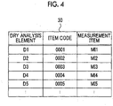
- Item codes indicating corresponding measurement items are attached to the respective dry analysis elements 25 in the form of bar codes or the like.
- the spotting unit 19 is provided with a reader (not illustrated), such as a charge coupled device (CCD) that reads the item codes.
- CCD charge coupled device
- the biochemical analysis apparatus 10 recognizes the measurement items of the respective dry analysis elements 25 with the item codes read by the reader.
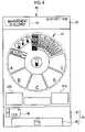
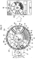
- the sample tray 13 is circular, and is constituted of a rotary disk 35 at an outer peripheral part thereof and a non-rotating part 36 at a central part thereof.
- the rotary disk 35 is annular and opens at a central part thereof, and the non-rotating part 36 is disposed in the opening.
- the rotary disk 35 is rotationally driven around an axis thereof.
- the non-rotating part 36 is disk-shaped, and is fixed to a central part of the sample tray 13 without rotating literally.
- sample installation parts 37A, 37B, 37C, 37D, and 37E are provided in the rotary disk 35 in order to collectively perform a plurality of sample analysis orders, as illustrated by divisions of two-dot chain lines.
- a sample container installation hole 38 in which the sample container 11 is installed and a cartridge installation hole 39 in which the cartridge 12 is installed are formed in each of the sample installation parts 37A to 37E.
- Alphabets "A”, “B”, “C”, “D”, and “E” as installation part-identification information for identifying the sample installation parts 37A to 37E, respectively, are attached to the sample installation parts 37A to 37E as indicated by reference sign INIDs and one-dot chain lines.
- the sample installation parts 37A to 37E are collectively denoted as the sample installation parts 37.
- Fig. 5 illustrates a state where the sample container 11 and the cartridge 12 are respectively installed in the sample container installation hole 38 and the cartridge installation hole 39 of the sample installation part 37A to which alphabet "A" is attached.
- one sample container 11 is installed in a set with one cartridge 12 in one sample installation part 37.
- a sample installation part 37 and a sample and the sample installation part 37 and a patient or a hospitalized animal from which the sample is collected are in one-to-one correspondence.
- two nozzle tip installation parts 45, three diluting solution installation parts 46, and two mixing cup installation parts 47 are provided as consumables installation parts in which the consumables to be used for the biochemical analysis are installed in addition to the sample installation parts 37.
- a tip rack 48 that accommodates a number of (twenty five in the present example) the nozzle tips 26 side by side is installed in each nozzle tip installation part 45.
- a diluting solution container 49, which accommodates a diluting solution for diluting the sample, is installed in each of the diluting solution installation parts 46.
- a plurality of (ten in the present example) mixing cups 50 for mixing the sample with the diluting solution is installed in each mixing cup installation part 47.
- the sample installation parts 37, the nozzle tip installation parts 45, the diluting solution installation parts 46, and the mixing cup installation parts 47 are disposed in an arcuate shape on the rotary disk 35. Additionally, the sample installation parts 37 are collectively disposed in a first region 55 that is about half of the rotary disk 35, and the nozzle tip installation parts 45, the diluting solution installation parts 46, and the mixing cup installation parts 47 are collectively disposed in a second region 56 that is the remaining region excluding the first region 55. That is, regions where the sample installation parts 37 and the consumables installation parts are disposed are clearly divided.
- the rotary disk 35 of the sample tray 13 is at a position where a center C1R of the first region 55 indicated by a one-dot chain line coincides with a center CA of the opening part 16 also indicated by a one-dot chain line. That is, the rotary disk 35 is at a position where the sample installation parts 37 are disposed on the opening part 16 side.
- the position illustrated in Fig. 5 is defined as a normal position.
- the rotary disk 35 moves to a position where a center C2R of the second region 56 indicated by a one-dot chain line coincides with the center CA of the opening part 16 also indicated by the one-dot chain line. That is, the rotary disk 35 moves to a position where the consumables installation parts (the nozzle tip installation parts 45, the diluting solution installation parts 46, and the mixing cup installation parts 47) are disposed on the opening part 16 side.
- the position illustrated in Fig. 6 is defined as a consumables replenishment position.
- a reference solution installation part 58 in which a reference solution container 57 accommodating the reference solution is installed, is provided as a consumables installation part in the non-rotating part 36.
- Each nozzle tip 26 is detached from each nozzle tip installation part 45, is mounted on the tip of the dispenser 22 as mentioned above, and is used for the spotting or the like of the sample.
- the diluting solution is used in a case where the sample has a concentration equal to or higher than a predetermined value, and cannot be analyzed as it is.
- the diluting solution is used, first, the sample is suctioned from the sample container 11 by the spotting mechanism 18 and is dispensed to the mixing cups 50. Next, the diluting solution is suctioned from each diluting solution container 49 and discharged to the mixing cups 50, and the sample and the diluting solution are mixed with each other.
- the sample diluted with the diluting solution is spotted on the spotting holes 25A of the dry analysis elements 25.
- the reference solution is used in the case of the potential difference measurement method.
- the reference solution is suctioned from the reference solution container 57 by the spotting mechanism 18, and is spotted on the dry analysis elements 25 together with the sample in the spotting unit 19.
- the spotting unit 19 is provided with an element holder 61 in which a spotting opening 60 is formed.
- the dry analysis elements 25 are sequentially supplied along a supply path R indicated by an arrow of a one-dot chain line from the cartridge 12 installed in the cartridge installation hole 39 of each sample installation part 37 that faces the spotting unit 19.
- the sample is spotted via the spotting opening 60 on the dry analysis elements 25 supplied to the element holder 61.
- a nozzle tip discard port which leads to a discard box 17 and to which used nozzle tips 26 are dropped and discarded, is provided between the spotting unit 19 and the first measuring unit 20.
- the first measuring unit 20 and the second measuring unit 21 are thermostats (incubators) that have heating means (not illustrated), such as a heater, and performs heating with the heating means to keep a temperature constant.
- the first measuring unit 20 receives the colorimetric type dry analysis elements 25, and performs measurement by the colorimetric method.
- the second measuring unit 21 receives the electrolyte type dry analysis elements 25, and performs measurement by the potential difference measurement method.
- the colorimetric type dry analysis elements 25 are kept at a constant temperature for a predetermined time by the first measuring unit 20, and thereby, a coloration reaction (chromogenic reaction) occurs in the sample spotted on the spotting holes 25A.
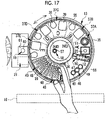
- the first measuring unit 20 comprises an annular rotating member 65 at an outer peripheral part thereof.
- An inverted-conical inclined rotating cylinder 66 is anchored to an inner peripheral part of the rotating member 65.
- a bearing 67 is attached to a lower part of the inclined rotating cylinder 66, and the rotating member 65 is supported by the bearing 67 and is rotatable.
- a plurality of element storage chambers 68 that store the plurality of dry analysis elements 25 are disposed in an arcuate shape in the rotating member 65.
- a circular photometric window 68A is formed at the center of each element storage chamber 68.
- a photometric head 69 is disposed at one corner of the lower part of the rotating member 65.
- the photometric head 69 measures the reflective optical density of the sample of the dry analysis element 25 stored in each element storage chamber 68 through the photometric window 68A. More specifically, the photometric head 69 radiates measurement light to the sample of the spotting hole 25A, in which the coloration reaction has occurred, via the photometric window 68A moved to a facing position by the rotation of the rotating member 65, and measures the reflected light.
- the dry analysis element 25 is pushed out from the element storage chamber 68 by a discarding mechanism (not illustrated), and is dropped and discarded into an inner hole 66A of the inclined rotating cylinder 66 that leads to the discard box 17.
- the second measuring unit 21 has a potentiometric probe (not illustrated).
- the potentiometric probe comes into contact with an electrolyte type dry analysis element 25 to measure the ion activity of specific ions, such as sodium, which is contained in the sample spotted on the electrolyte type dry analysis element 25. Even in this case, similarly to the case of the colorimetric type, after the measurement, the dry analysis element 25 is transferred from the second measuring unit 21 to an element discard port (not illustrated) leading to the discard box 17 and is discarded.
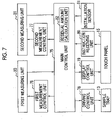
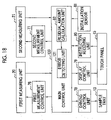
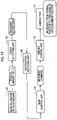
- a main control unit 75 integrally controls the entire biochemical analysis apparatus 10.
- a first measurement control unit 76, a second measurement control unit 77, a driving control unit 78, a display control unit 79, an instruction receiving unit 80, and an installation sensor 81 are connected to the main control unit 75. Additionally, the main control unit 75 is provided with a residual amount calculation unit 82.
- the first measurement control unit 76 controls driving of the heating means of the first measuring unit 20 and the rotation of the rotating member 65, and controls driving of the photometric head 69 to cause the photometric head 69 to measure the reflective optical density of the sample.
- the second measurement control unit 77 controls driving of the heating means of the second measuring unit 21, and controls driving of the potentiometric probe to cause the potentiometric probe to measure the ion activity of the sample.
- the first measuring unit 20 outputs numerical values, indicating the amounts of contained components of the sample according to the reflective optical density measured by the photometric head 69, to the main control unit 75.
- the second measuring unit 21 outputs numerical values, indicating the amounts of contained components of the sample according to the ion activity measured by the potentiometric probe, to the main control unit 75.
- the main control unit 75 outputs the numerical values to the display control unit 79.
- the driving control unit 78 controls driving of the sample tray 13.
- the driving control unit 78 is a driver of a motor (not illustrated) that rotationally drives the rotary disk 35 of the sample tray 13 around an axis thereof.
- the main control unit 75 counts the elapsed time from the start of the biochemical analysis for the sample installed in each of the sample installation parts 37A to 37E.
- the main control unit 75 detects the end of the biochemical analysis of the sample installed in the relevant sample installation part 37 in a case where the elapsed time reaches a required time for the biochemical analysis and the measurement is ended in the first measuring unit 20 or the second measuring unit 21.
- the main control unit 75 has detected the end of the biochemical analysis, it is possible to take out the sample container 11 and the cartridge 12 from the relevant sample installation part 37, and install new sample container 11 and cartridge 12.
- the required time is a time that varies in accordance with the methods and purposes of the biochemical analysis, and is known.
- the display control unit 79 controls display of various screens to the touch panel 15.
- the instruction receiving unit 80 receives operation instructions input from the user via the touch panel 15.
- the installation sensor 81 is, for example, a reflective optical sensor including a light emitter and a light receiver, and detects the presence or absence of installation of the sample containers 11 to the sample container installation holes 38 of the sample installation parts 37 and the presence or absence of installation of the cartridges 12 to the cartridge installation holes 39. Additionally, the installation sensor 81 are also provided in the consumables installation parts including the nozzle tip installation parts 45, the diluting solution installation parts 46, the mixing cup installation parts 47, and the reference solution installation part 58, and also detects the presence or absence of installation of respective consumables to the consumables installation parts.
- the main control unit 75 outputs detection results of the installation sensor 81 to the display control unit 79.
- the residual amount calculation unit 82 calculates residual amounts RA (refer to Fig.9 ) of the consumables. Specifically, the residual amount calculation unit 82 subtracts the numbers of used consumables from full replenishment numbers (twenty five in the case of the nozzle tips 26 and ten in the case of the mixing cups 50) of consumables in the consumables installation parts to calculate the residual amounts RA. The residual amount calculation unit 82 outputs the calculated residual amounts RA to the display control unit 79.
- a driving control unit of the spotting mechanism 18 a driving control unit of a supply mechanism that supplies the dry analysis elements 25 from the cartridge 12 to the spotting unit 19, a plasma filtration unit (not illustrated) that extracts plasma components from whole blood that is a sample, a driving control unit of a centrifugal separation unit (not illustrated), or the like is connected to the main control unit 75 by the display control unit 79.
- Fig. 8 illustrates a main screen 90 to be displayed on the touch panel 15.
- a layout diagram 91 is displayed substantially at the center of the main screen 90.
- a message display region 92 is disposed at an upper part of the main screen 90, and a result display switching region 93 is disposed at a lower part of the main screen 90.
- a message 94 indicating the progress situations of the biochemical analysis and current data and time are displayed on the message display region 92.
- the result display switching region 93 is provided with a call button display region 95 and a summary display button 96. Additionally, button display regions 97A and 97B are provided between the layout diagram 91 and the result display switching region 93.
- a call button 98 for displaying results of the biochemical analysis for each sample is operably displayed on the call button display region 95.
- the instruction receiving unit 80 receives a display instruction for the analysis results.
- the display control unit 79 displays a result display screen (not illustrated) instead of the main screen 90 on the touch panel 15. Numerical values of a plurality of measurement items are displayed side by side on the result display screen. The user can confirm the results of the biochemical analysis through the result display screen.
- the display control unit 79 displays a result display screen (not illustrated) capable of browsing all past results including all results on the day on the touch panel 15.
- a flag "START” is retractably displayed on the button display region 97A.
- the button display region 97A functions as a start button giving an instruction for the start of the analysis.
- the instruction receiving unit 80 receives the analysis start instruction.
- a flag "STOP” is retractably displayed on the button display region 97B (refer to Fig. 10 ).
- the button display region 97B functions as a stop button giving an instruction for the stop of the analysis.
- the instruction receiving unit 80 receives the analysis stop instruction.
- the main control unit 75 stops the analysis.
- the layout diagram 91 schematically illustrates an array state of the sample installation parts 37 and the consumables installation parts (the nozzle tip installation parts 45, the diluting solution installation parts 46, the mixing cup installation parts 47, and the reference solution installation part 58) in the rotary disk 35 of the sample tray 13.
- the layout diagram 91 is provided with first display sections 100A, 100B, 100C, 100D, and 100E corresponding to the sample installation parts 37A to 37E, and second display sections 101, 102, 103, and 104 corresponding to the consumables installation parts.
- Installation part-identification information INID is attached to the first display sections 100A to 100E, similarly to the sample installation parts 37A to 37E.
- FIG. 9 reference signs of corresponding installation parts are attached to reference signs of the respective display sections in parentheses in order to clarify a correspondence relationship between the respective display sections and the respective installation parts.
- the first display sections 100A to 100E may be collectively denoted as the first display sections 100.
- the display control unit 79 displays a residual amount RA of the mixing cups 50. That is, the display control unit 79 is equivalent to the first display control unit.
- the display control unit 79 paints the residual amount RA in a specific color (for example, red) as illustrated by hatching, and paints the second display section 103 in a specific color (for example, pink). That is, the second display section 103 in a case where the residual amount RA of the mixing cup 50 is zero is displayed separately from a second display section 103 (a second display section 103 at a 10 o'clock position in Fig. 9 ) of which a residual amount RA is not zero.
- a specific color for example, red
- a specific color for example, pink
- the display control unit 79 does not display the residual amounts RA. However, in a case where the residual amount RA reaches zero, similarly to the second display section 103 at the 12 o'clock position, the display control unit 79 paints the second display sections 101, 102, and 104 in pink.
- the first display sections 100 function as operation buttons that can be operated by the user's fingers.
- the display control unit 79 displays an order screen (not illustrated) related to orders for the biochemical analysis of the sample installed in a sample installation part 37 corresponding to the operated first display section 100 instead of the main screen 90 on the touch panel 15.
- the user inputs orders including sample IDs (identification data) for identifying the sample through the order screen, and gives input instructions for the orders to the instruction receiving unit 80.
- the sample IDs are, for example, Romanic notations of the names of patients or hospitalized animals from which samples are collected (refer to Fig. 10 ).
- the main control unit 75 drives the installation sensor 81, and detects the presence or absence of installation of a sample container 11 and a cartridge 12 to the sample installation part 37 corresponding to the first display section 100 in which the order input instructions have been received by the instruction receiving unit 80.
- the main control unit 75 drives the spotting mechanism 18 to start spotting.
- the sample containers 11 and the cartridges 12 are installed in all the sample installation parts 37A to 37E, firstly, the spotting is performed on the dry analysis elements 25 of the sample installation part 37A, then the spotting is sequentially performed on the dry analysis elements 25 of the sample installation part 37B and the dry analysis elements 25 of the sample installation part 37C, and finally, the spotting is performed on the dry analysis elements 25 of the sample installation part 37E.
- the rotary disk 35 of the sample tray 13 is rotationally driven under the control of the driving control unit 78 such that a sample installation part 37 as a spotting target faces the spotting unit 19.
- the display control unit 79 displays a warning screen (not illustrated) prompting the installation of the sample container 11 and the cartridge 12 instead of the main screen 90 on the touch panel 15.
- Fig. 10 is an example of display of the main screen 90 in a case where the spotting is started.
- the display control unit 79 changes the message 94 in the message display region 92 from "Measurement is allowed" in Fig. 8 to "During spotting".
- a first display section 100 corresponding to a sample installation part 37 being currently spotted on a dry analysis element 25 and a first display section 100 corresponding to a sample installation part 37 waiting for spotting are painted in different colors (for example, in red-brown during spotting and in cream during waiting) as illustrated by hatching. This painting in specific colors also shows that the installation of a sample container 11 and a cartridge 12 to the relevant sample installation part 37 has been detected (the presence or absence of installation of a sample container 11 and a cartridge 12).
- Fig. 10 illustrates a case where the installation of the sample containers 11 and the cartridges 12 to the sample installation parts 37A to 37C corresponding to the first display sections 100A to 100C are detected, the sample installation part 37A is being spotted, and the sample installation parts 37B and 37C are waiting.
- reference signs SIDs indicated by being enclosed by broken lines are sample IDs.
- the measurement is not started, and the results of the biochemical analysis are not yet output.
- the call button 98 is not displayed on the call button display region 95 in accordance with an operation.
- the second display sections 101 to 104 function as operation buttons that allow the user to operate with his/her fingers, similarly to the first display sections 100.
- the instruction receiving unit 80 receives the movement instruction for the sample tray 13. That is, the second display sections 101 to 104 are equivalent to a first driving button that outputs the movement instruction to the instruction receiving unit 80.
- the main control unit 75 In a case where the movement instruction for the sample tray 13 is received by the instruction receiving unit 80, the main control unit 75 outputs a movement command for the sample tray 13 to the driving control unit 78.
- the driving control unit 78 receives the movement command to move the sample tray 13 from the normal position to the consumables replenishment position.
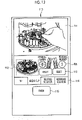
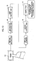
- the display control unit 79 displays a guide screen 110 illustrated in Fig. 12 instead of the main screen 90 on the touch panel 15.
- Replenishment guides 111 of the consumables are displayed at an upper part of the guide screen 110.
- the replenishment guides 111 are photographs or illustrations of the sample tray 13 at the consumables replenishment position taken from the opening part 16 side.
- an aspect in which the consumables are replenished with user's hands is displayed on the replenishment guides 111.
- Fig. 12 illustrates a case where the replenishment guides 111 indicating an aspect in which a second display section 103 is operated and a mixing cup installation part 47 corresponding to the second display section 103 is replenished with the mixing cups 50 are displayed, subsequent to the example of Fig. 11 .
- the replenishment guides 111 may be moving images with voice guides without being limited to still images, such as photographs and illustrations.
- a position display diagram 112 is displayed on a lower left side of the replenishment guides 111.
- the position display diagram 112 is a diagram indicating the position of consumables to be replenished. More specifically, the position display diagram 112 is a perspective view of the sample tray 13 in which the consumables (the mixing cups 50 in the present example) to be replenished is painted in a specific color (for example, in orange) as illustrated by hatching and are displayed separately from the other consumables.
- the residual amounts RA are displayed on the right side of the position display diagram 112, similarly to the second display sections 103 of the layout diagram 91, and reset buttons 113 are displayed below the residual amounts RA.
- the residual amount calculation unit 82 resets a residual amount RA, which has been calculated so far, to a full replenishment number.
- replenishment guides 111, the position display diagram 112, and the like regarding the mixing cups 50 are illustrated in Fig. 12 , the replenishment guides 111, the position display diagram 112, and the like are prepared for every consumable, and it is possible to switch displays with lower tabs 114.
- Fig. 12 illustrates the case where the second display section 103 corresponding to the mixing cup installation part 47 is operated, the replenishment guides 111, the position display diagram 112, and the like regarding the mixing cups 50 are displayed.
- the display control unit 79 displays the replenishment guides 111, the position display diagrams 112, and the like regarding the other consumables.
- the replenishment guides 111, the position display diagram 112, and the like regarding the nozzle tips 26 are displayed instead of the replenishment guides 111, the position display diagram 112, and the like regarding the mixing cups 50 of Fig. 12 .
- a lowermost part of the guide screen 110 is provided with a finish button 115.
- the instruction receiving unit 80 receives a return instruction for the sample tray 13. That is, the finish button 115 is equivalent to a second driving button that outputs the return instruction to the instruction receiving unit 80 in accordance with an operation.
- the main control unit 75 In a case where the return instruction for the sample tray 13 is received by the instruction receiving unit 80, the main control unit 75 outputs a return command for the sample tray 13 to the driving control unit 78.
- the driving control unit 78 receives the return command to move the sample tray 13 from the consumables replenishment position to the normal position.
- Fig. 14 the user opens the lid 14 to open the opening part 16. Then, the sample containers 11, which accommodate samples collected from target patients or target hospitalized animals for the biochemical analysis, are installed in the sample container installation holes 38 via the opening part 16, and the cartridges 12, which accommodate the unused dry analysis elements 25, are installed in the cartridge installation holes 39 via the opening part 16 (Step ST100).
- the sample tray 13 is at the normal position. For this reason, as illustrated in Fig. 15 , a user's hand makes an easy access to the sample installation parts 37. Hence, the user can easily install the sample containers 11 and the cartridge 12 in the sample installation parts 37.
- Step ST110 of Fig. 14 after the installation of the sample containers 11 and the cartridges 12, the user closes the lid 14, and operates the first display sections 100 of the main screen 90 corresponding to the sample installation parts 37 in which the sample containers 11 and the cartridges 12 are installed.
- an order screen is displayed in place of the main screen 90 by the display control unit 79.
- the user inputs orders through the order screen (Step ST120). Accordingly, input instructions for the orders are received by the instruction receiving unit 80 (Step ST130).
- Step ST140 After the input of the orders, the user operates the button display region 97A that functions as the start button. Accordingly, a start instruction for the analysis is received by the instruction receiving unit 80 (Step ST140).
- Step ST150 the presence or absence of installation of the sample containers 11 and the cartridges 12 to the sample installation parts 37 is detected by the installation sensor 81 under the control of the main control unit 75.
- Step ST160 spotting to the dry analysis elements 25 is performed by the spotting mechanism 18 (Step ST160).
- measurement of numerical values of respective measurement items is performed by the first measuring unit 20 and the second measuring unit 21 (Step ST170).
- Step ST180 the call button 98 is displayed on the call button display region 95 by the display control unit 79 (Step ST180).
- Step ST190 the result display screen is displayed in place of the main screen 90 by the display control unit 79 (Step ST200).
- the series of processing from Step ST160 to Step ST200 are repeatedly continued until the analysis of all orders received in Step (ST130) ends (YES in Step ST210).
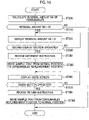
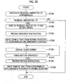
- the residual amounts RA of consumables are calculated (Step ST300).
- the fact that the residual amounts RA reach zero is displayed on the second display sections 101 to 104 by the display control unit 79 (Step ST320).
- the fact that the residual amount RA of the mixing cups 50 is zero is displayed by the residual amount RA itself and a display color.
- the facts that the residual amounts of the nozzle tips 26, the diluting solutions, and the reference solution are zero are displayed in the display color.
- Step ST340 an instruction receiving step
- Step ST350 a driving control step
- Step ST360 of Fig. 16 in a case where the movement instruction is received by the instruction receiving unit 80, the guide screen 110 is displayed in place of the main screen 90 by the display control unit 79 as illustrated in Fig. 12 .
- the user operates the reset buttons 113 after the consumables are replenished in accordance with the replenishment guides 111 of the guide screen 110. Accordingly, the residual amounts RA, which have been calculated so far by the residual amount calculation unit 82, are reset to the full replenishment numbers.
- Step ST370 After the operation of the reset buttons 113, the user further operates the finish button 115 (YES in Step ST370). Accordingly, a return instruction for the sample tray 13 is received by the instruction receiving unit 80 (Step ST380).
- a return command is output from the main control unit 75 to the driving control unit 78. Then, the sample tray 13 is moved from the consumables normal position to the replenish position by the driving control unit 78 (Step ST390).
- the display control unit 79 schematically displays the array state of the sample installation parts 37 and the consumables installation parts 45 to 47 and 58 in the sample tray 13, displays the first display sections 100 corresponding to the sample installation parts 37 and displays the layout diagram 91 provided with the second display sections 101 to 104 corresponding to the consumables installation parts 45 to 47 and 58 on the touch panel 15, and causes the second display sections 101 to 104 to function as the first driving button that outputs the movement instruction to the instruction receiving unit 80, the operation is intuitive for the user and is easy for the user to understand.
- the first driving button may be provided separately from the second display sections 101 to 104.
- a physical button attached to the apparatus body 10A may be caused to function as the first driving button instead of an operation button to be displayed on the touch panel 15.
- a physical button attached to the apparatus body 10A may be made to function as the second driving button instead of the illustrated finish button 115.
- the display control unit 79 displays the residual amounts RA of the mixing cups 50 on the second display sections 103, the user can always confirm the residual amounts RA of the mixing cups 50, and can monitor a timing at which the mixing cups 50 are replenished.
- the residual amounts RA of the mixing cups 50 may be displayed on the second display sections 101, 102, and 104.
- the residual amounts RA may be displayed on, for example, exclusive screens or the like to be displayed instead of the main screen 90 separately from the second display sections 101 to 104.
- the driving control unit 78 moves the sample tray 13 from the consumables replenishment position to the normal position.
- the sample tray 13 can be simply returned to the normal position by one-touch operation.
- the consumables replenishment position is a position where the center C2R of the second region 56 coincides with the center CA of the opening part 16, it is easy to equally make an access to any consumables installation parts in the consumables replenishment position. Additionally, since the consumables replenishment position is limited to one position, the driving control of the sample tray 13 is simple.
- the "coincidence position” includes not only a case where the positions of the centers completely coincide with each other but also a case where deviation between the positions of the centers falls within a certain degree of allowable range (for example, ⁇ 10° or the like).
- the consumables replenishment position may be a position where the consumables installation parts are disposed on the opening part 16 side, and may not necessarily be the position where the center C2R of the second region 56 coincides with the center CA of the opening part 16 or the position where the center of each consumables installation part coincides with the center of the opening part 16.
- the sample tray 13 in a case where the second display sections 101 to 104 equivalent to the first driving button is operated, the sample tray 13 may be moved from the normal position to the consumables replenishment position.
- the invention is not limited to this. Rather, in addition to what has been described above, in the specific embodiment illustrated in Figs. 18 to 20 , in a case where an error regarding the consumables is detected, the sample tray 13 may be moved from the normal position to the consumables replenishment position.
- the main control unit 120 is provided with an error detecting unit 121 in addition to the residual amount calculation unit 82.
- the residual amount calculation unit 82 outputs the fact to the error detecting unit 121.
- the error detecting unit 121 detects that the residual amount RA of the consumables reaches zero, as an error regarding the consumables.
- the error detecting unit 121 outputs the movement instruction to the instruction receiving unit 80.
- the flow of the subsequent processing is the same as illustrated in Fig. 11 .
- Step ST310 in a case where the residual amounts RA reach zero (YES in Step ST310), the fact that the residual amounts RA are zero is displayed on the second display sections 101 to 104 by the display control unit 79, and an error is detected by the error detecting unit 121 (Step ST500). Then, the movement instruction for the sample tray 13 is output from the error detecting unit 121, and the movement instruction is received by the instruction receiving unit 80 without the operation of the second display sections 101 to 104 (Step ST340, an instruction receiving step).
- the guide screen 110 is displayed on the touch panel 15 by the display control unit 79 (Step ST360).
- the replenishment guides 111 are equivalent to guides showing a method for handling the error. That is, the display control unit 79 is equivalent to the second display control unit.
- the movement instruction for the sample tray 13 is output to the instruction receiving unit 80.
- the sample tray 13 can be automatically moved from the normal position to the consumables replenishment position without waiting for the operation of the second display sections 101 to 104.
- the guides (replenishment guides 111) showing the method for handling the error are displayed.
- the error to be detected by the error detecting unit 121 may be deviation between installation positions of the consumables, installation of nonstandard consumables, leakage of the diluting solutions and the reference solution, or the like instead of or in addition to the residual amounts RA of consumables having reached zero.
- the display posture of the layout diagram 91 is always the same such that the first region 55 on the opening part 16 side (front side) is a lower side, and the second region 56 on the side (back side) opposite to the opening part 16 is an upper side.
- the display control unit 79 changes the display posture of the layout diagram 91 in accordance with the rotational position of the rotary disk 35 of the sample tray 13.
- Fig. 21 illustrates a case where the rotary disk 35 is rotationally driven to a position where the sample installation part 37D faces the spotting unit 19.
- the display posture of the layout diagram 91 of the main screen 90 is also changed by the display control unit 79 such that the first display section 100D corresponding to the sample installation part 37D is at a 9 o'clock position in accordance with the rotational position of the rotary disk 35.
- the guide screen 110 is displayed after the layout diagram 91 is changed to a display posture imitating the consumables replenishment position in the main screen 90. This allows the movement of the rotary disk 35 to the consumables replenishment position to visually appeal to the user.
- the shape of the sample tray may not be circular, and may be, for example, rectangular.
- sample IDs may be patient IDs or hospitalized animals IDs including symbols and numbers attached to patients or hospitalized animals in a hospital where the biochemical analysis apparatus 10 is installed.
- processors which execute various kinds of processing, such as the driving control unit 78, the display control unit 79 that is the first and second display control units, the instruction receiving unit 80, and the residual amount calculation unit 82, and the error detecting unit 121 are various processors as illustrated below.
- the various processors include a central processing unit (CPU) that is a general-purpose processor, a programmable logic device (PLD) that is a processor capable of changing a circuit configuration after manufacture of a field programmable gate array (FPGA) or the like, and exclusive electric circuits, which are processors having circuit configurations exclusively designed to execute specific processing, such as an application specific integrated circuit (ASIC).
- CPU central processing unit
- PLD programmable logic device
- FPGA field programmable gate array
- exclusive electric circuits which are processors having circuit configurations exclusively designed to execute specific processing, such as an application specific integrated circuit (ASIC).
- One processing unit may be constituted of one of these various processors, or may be constituted of a combination of two or more same or different types of processors (for example, a combination of a plurality of the FPGAs or a combination of the CPU and the FPGA). Additionally, the plurality of processing units may be constituted of one processor. As an example in which the plurality of processing units are constituted of the one processor, firstly, there is a form in which one processor is constituted of a combination of one or more CPUs and software and this processor functions as the plurality of processing units.
- SOC system-on-chip
- IC integrated circuit
- circuit elements such as semiconductor elements
Landscapes
- Chemical & Material Sciences (AREA)
- Biochemistry (AREA)
- Physics & Mathematics (AREA)
- Health & Medical Sciences (AREA)
- Life Sciences & Earth Sciences (AREA)
- Analytical Chemistry (AREA)
- General Health & Medical Sciences (AREA)
- General Physics & Mathematics (AREA)
- Immunology (AREA)
- Pathology (AREA)
- Chemical Kinetics & Catalysis (AREA)
- Engineering & Computer Science (AREA)
- Quality & Reliability (AREA)
- Automatic Analysis And Handling Materials Therefor (AREA)
Claims (11)
- Biochemische Analysevorrichtung (10) aufweisend:einen Probenteller (13), der ausgestattet ist mit einem Probenunterbringungsteil (37), in dem ein Probenbehälter (11) untergebracht ist, der eine Probe aufnimmt, die einer biochemischen Analyse unterzogen werden soll, und mit einem Verbrauchsmaterial-Unterbringungsteil (45, 46, 47), in dem Verbrauchsmaterialien, die für die biochemische Analyse verwendet werden sollen, untergebracht werden;einen Vorrichtungskörper (10A), der den Probenteller (13) aufnimmt;einen Öffnungsteil (16), der in dem Vorrichtungskörper (10A) vorgesehen ist und zu dem Probenteller (13) führt;eine Anweisungsempfangseinheit (80), die eine Bewegungsanweisung zum Bewegen des Probentellers (13) von einer Normalposition, in der der Probenunterbringungsteil (37) an der Seite des Öffnungsteils (16) angeordnet ist, zu einer Verbrauchsmaterialien-Nachfüllposition, in der der Verbrauchsmaterialien-Unterbringungsteil (45, 46, 47, 58) an der Seite des Öffnungsteils (16) angeordnet ist, empfängt; undeine Antriebssteuereinheit (78), die den Antrieb des Probentellers (13) steuert und den Probenteller von der Normalposition zu der Verbrauchsmaterialien-Nachfüllposition bewegt in einem Fall, wenn die Bewegungsanweisung von der Anweisungsempfangseinheit (80) empfangen wird;wobei die biochemische Analysevorrichtung dadurch gekennzeichnet ist, dass sie außerdem aufweisteinen ersten Antriebsbutton (101, 102, 103, 104), der einem Arbeitsvorgang entsprechend die Bewegungsanweisung an die Anweisungsempfangseinheit (80) ausgibt; undeine erste Anzeigesteuereinheit (79), die einen Anordnungszustand des Probenunterbringungsteils (37) und des Verbrauchsmaterialien-Unterbringungsteils (45, 46, 47, 58) in dem Probenteller (13) schematisch anzeigt und eine Steuerung dergestalt durchführt, dass ein Bestückungsplan (91), der ausgestattet ist mit einem ersten Anzeigeabschnitt (100), der dem Probenunterbringungsteil (37) entspricht, und einem zweiten Anzeigeabschnitt (101, 102, 103, 104), der dem Verbrauchsmaterialien-Unterbringungsteil (45, 46, 47, 58) entspricht, auf einer Anzeigeeinheit angezeigt wird,wobei mindestens ein Teilbereich des zweiten Anzeigeabschnitts (101, 102, 103, 104) als der erste Antriebsbutton wirkt.
- Biochemische Analysevorrichtung (10) nach Anspruch 1,
wobei die erste Anzeigesteuereinheit (79) eine Restmenge der Verbrauchsmaterialien auf dem zweiten Anzeigeabschnitt (101, 102, 103, 104) anzeigt. - Biochemische Analysevorrichtung (10) nach Anspruch 1 oder 2,wobei der Probenteller (13) kreisförmig ist und unter der Steuerung der Antriebssteuereinheit (78) um seine Achse drehend angetrieben wird, undwobei die erste Anzeigesteuereinheit (79) eine Positionsanzeige des Bestückungsplans (91) einer Rotationsposition des Probentellers (13) entsprechend ändert.
- Biochemische Analysevorrichtung (10) nach einem der Ansprüche 1 bis 3, außerdem aufweisend:
eine Fehlererkennungseinheit (121), die einen Fehler bezüglich der Verbrauchsmaterialien erkennt und in einem Fall, in dem der Fehler erkannt wird, die Bewegungsanweisung an die Anweisungsempfangseinheit (80) ausgibt. - Biochemische Analysevorrichtung (10) nach Anspruch 4, außerdem aufweisend:
eine zweite Anzeigesteuereinheit (79), die eine Steuerung dergestalt durchführt, dass in einem Fall, in dem der Fehler von der Fehlererkennungseinheit (121) erkannt wird, auf einer Anzeigeeinheit Hinweise (111) angezeigt werden, die ein Verfahren zum Umgang mit dem Fehler zeigen. - Biochemische Analysevorrichtung (10) nach Anspruch 4 oder 5,
wobei die Fehlererkennungseinheit (121) als den Fehler erkennt, dass sich die Restmenge der Verbrauchsmaterialien Null nähert. - Biochemische Analysevorrichtung (10) nach einem der Ansprüche 1 bis 6, außerdem aufweisend:einen zweiten Antriebsbutton (115), der entsprechend einem Arbeitsvorgang an die Anweisungsempfangseinheit (80) eine Zurücksetzungsanweisung zum Zurücksetzen des Probentellers (13) von der Verbrauchsmaterialien-Nachfüllposition zu der Normalposition ausgibt,wobei die Antriebssteuereinheit (78) in einem Fall, in dem der zweite Antriebsbutton (15) betätigt wird und die Zurücksetzungsanweisung von der Anweisungsempfangseinheit (80) empfangen wird, den Probenteller (13) von der Verbrauchsmaterialien-Nachfüllposition zu der Normalposition bewegt.
- Biochemische Analysevorrichtung (10) nach einem der Ansprüche 1 bis 7,wobei der Probenteller (13) kreisförmig ist und unter der Steuerung der Antriebskontrolleinheit (78) um seine Achse drehend angetrieben wird, undwobei der Probenunterbringungsteil (37) und der Verbrauchsmaterialien-Unterbringungsteil (45, 46, 47, 58) in Bogenform angeordnet sind.
- Biochemische Analysevorrichtung (10) nach einem der Ansprüche 1 bis 8,wobei eine Mehrzahl der Probenunterbringungsteile (37A, 37B, 37C, 37D, 37E) und eine Mehrzahl der Verbrauchsmaterialien-Unterbringungsteile (45, 46, 47, 58) vorgesehen sind,wobei die Mehrzahl der Probenunterbringungsteile (37A, 37B, 37C, 37D, 37E) gesammelt in einem ersten Bereich (55) des Probentellers (13) angeordnet sind, undwobei die Mehrzahl der Verbrauchsmaterialien-Unterbringungsteile (45, 46, 47, 58) gesammelt in einem zweiten Bereich (56) angeordnet sind, der ein den ersten Bereich (55) ausschließender, verbleibender Bereich ist.
- Biochemische Analysevorrichtung (10) nach Anspruch 9,
wobei die Verbrauchsmaterialien-Nachfüllposition eine Position ist, in der ein Zentrum des zweiten Bereichs (56) mit einem Zentrum des Öffnungsteils (16) zusammenfällt. - Verfahren zum Betreiben einer biochemischen Analysevorrichtung (10), aufweisend einen Probenteller (13), der ausgestattet ist mit einem Probenunterbringungsteil (37), in dem ein Probenbehälter (11) untergebracht ist, der eine Probe, die einer biochemischen Analyse unterzogen werden soll, aufnimmt, und mit einem Verbrauchsmaterialien-Unterbringungsteil (45, 46, 47, 58), in dem Verbrauchsmaterialien untergebracht werden, die für die biochemische Analyse verwendet werden sollen, einen Vorrichtungskörper (10A), der den Probenteller (13) aufnimmt, und einen Öffnungsteil (16), der in dem Vorrichtungskörper (10A) vorgesehen ist und zu dem Probenteller (13) führt, wobei das Verfahren aufweist:einen Anweisungsempfangsschritt (ST 340) des Empfangens einer Bewegungsanweisung zum Bewegen des Probentellers (13) von einer Normalposition, in der der Probenunterbringungsteil (37) an der Seite des Öffnungsteils (16) angeordnet ist, zu einer Verbrauchsmaterialien-Nachfüllposition, in der der Verbrauchsmaterialien-Unterbringungsteil (37) an der Seite des Öffnungsteils (16) angeordnet ist; undeinen Antriebssteuerschritt (ST 350) des Steuerns des Antriebs des Probentellers (13) und des Bewegens des Probentellers (13) in einem Fall, in dem die Bewegungsanweisung in dem Anweisungsempfangsschritt empfangen wird, von der Normalposition in die Verbrauchsmaterialien-Nachfüllposition, dadurch gekennzeichnet, dass das Verfahren außerdem aufweisteinen ersten Anzeigesteuerschritt des schematisch Anzeigens eines Anordnungszustands des Probenunterbringungsteils (37) und des Verbrauchsmaterialien-Unterbringungsteils (45, 46, 47, 58) in dem Probenteller (13), und des Durchführens einer Steuerung dergestalt, dass ein Bestückungsplan (91), der ausgestattet ist mit einem ersten Anzeigeabschnitt (100), der dem Probenunterbringungsteil (37) entspricht, und mit einem zweiten Anzeigeabschnitt (101, 102, 103, 104), der dem Verbrauchsmaterialien-Unterbringungsteil (45, 46, 47, 58) entspricht, auf einer Anzeigeeinheit angezeigt wird; undeinen Funktionsschritt, bei dem mindestens ein Teilbereich des zweiten Anzeigeabschnitts (101, 102, 103, 104) als ein erster Antriebsbutton wirkt, der einem Arbeitsvorgang entsprechend die Bewegungsanweisung an die Anweisungsempfangseinheit (80) ausgibt.
Applications Claiming Priority (2)
| Application Number | Priority Date | Filing Date | Title |
|---|---|---|---|
| JP2017025851 | 2017-02-15 | ||
| PCT/JP2018/003348 WO2018150884A1 (ja) | 2017-02-15 | 2018-02-01 | 生化学分析装置とその作動方法 |
Publications (3)
| Publication Number | Publication Date |
|---|---|
| EP3584582A1 EP3584582A1 (de) | 2019-12-25 |
| EP3584582A4 EP3584582A4 (de) | 2020-06-24 |
| EP3584582B1 true EP3584582B1 (de) | 2022-09-28 |
Family
ID=63170201
Family Applications (1)
| Application Number | Title | Priority Date | Filing Date |
|---|---|---|---|
| EP18754571.0A Active EP3584582B1 (de) | 2017-02-15 | 2018-02-01 | Biochemischer analysator und verfahren zu dessen betrieb |
Country Status (6)
| Country | Link |
|---|---|
| US (1) | US11662356B2 (de) |
| EP (1) | EP3584582B1 (de) |
| JP (1) | JP6690028B2 (de) |
| CN (1) | CN110300894A (de) |
| ES (1) | ES2928575T3 (de) |
| WO (1) | WO2018150884A1 (de) |
Families Citing this family (9)
| Publication number | Priority date | Publication date | Assignee | Title |
|---|---|---|---|---|
| JP1629185S (de) * | 2018-10-31 | 2019-08-05 | ||
| CN110045133A (zh) * | 2019-04-30 | 2019-07-23 | 上海仁度生物科技有限公司 | 一种耗材监控装置及监控方法 |
| EP3983797B1 (de) * | 2019-06-14 | 2024-01-24 | DeLaval Holding AB | Steuerungseinheit für eine milchanalysevorrichtung |
| CN112666361A (zh) * | 2019-09-29 | 2021-04-16 | 深圳迈瑞生物医疗电子股份有限公司 | 耗材信息的处理的方法以及相关设备 |
| JP7718799B2 (ja) * | 2020-01-27 | 2025-08-05 | 株式会社島津製作所 | 分析システム |
| USD969619S1 (en) * | 2020-10-19 | 2022-11-15 | Aroma Technology Co., Ltd. | Portable bean roast degree analyzer |
| CN114544989A (zh) * | 2020-11-25 | 2022-05-27 | 深圳迈瑞生物医疗电子股份有限公司 | 一种样本分析装置和方法 |
| CN114544986A (zh) * | 2020-11-25 | 2022-05-27 | 深圳迈瑞生物医疗电子股份有限公司 | 一种样本分析装置和方法 |
| CN114544991B (zh) * | 2020-11-25 | 2025-12-09 | 深圳迈瑞生物医疗电子股份有限公司 | 一种样本分析装置及其控制方法 |
Family Cites Families (14)
| Publication number | Priority date | Publication date | Assignee | Title |
|---|---|---|---|---|
| JP3558853B2 (ja) * | 1998-02-17 | 2004-08-25 | シャープ株式会社 | ガイダンス情報表示装置 |
| JP3919107B2 (ja) * | 2003-03-19 | 2007-05-23 | 富士フイルム株式会社 | 自動分析装置 |
| JP4033060B2 (ja) * | 2003-07-17 | 2008-01-16 | 株式会社日立ハイテクノロジーズ | 自動分析装置 |
| JP5009684B2 (ja) * | 2006-06-30 | 2012-08-22 | シスメックス株式会社 | 試料分析装置 |
| CN101097222B (zh) * | 2006-06-30 | 2012-08-29 | 希森美康株式会社 | 试样分析仪 |
| JP5137436B2 (ja) * | 2007-03-29 | 2013-02-06 | シスメックス株式会社 | 試料分析装置 |
| JP2009210536A (ja) | 2008-03-06 | 2009-09-17 | Sysmex Corp | 試料分析装置、試料分析方法及びコンピュータプログラム |
| JP5295612B2 (ja) * | 2008-04-04 | 2013-09-18 | 株式会社東芝 | 自動分析装置 |
| JP5553554B2 (ja) * | 2009-08-27 | 2014-07-16 | シスメックス株式会社 | 検体分析装置 |
| JP5634969B2 (ja) | 2011-09-30 | 2014-12-03 | 富士フイルム株式会社 | 生化学分析装置および回転搬送方法 |
| JP2013217741A (ja) * | 2012-04-06 | 2013-10-24 | Hitachi High-Technologies Corp | 自動分析装置 |
| JP5988830B2 (ja) * | 2012-10-30 | 2016-09-07 | シスメックス株式会社 | 検体分析装置 |
| WO2015143084A1 (en) * | 2014-03-20 | 2015-09-24 | Beckman Coulter, Inc. | Instrument interface with presentation unit display |
| WO2018005239A1 (en) * | 2016-07-01 | 2018-01-04 | Siemens Healthcare Diagnostics Inc. | Method and apparatus to automatically transfer and open a reagent container |
-
2018
- 2018-02-01 CN CN201880012096.XA patent/CN110300894A/zh active Pending
- 2018-02-01 WO PCT/JP2018/003348 patent/WO2018150884A1/ja not_active Ceased
- 2018-02-01 EP EP18754571.0A patent/EP3584582B1/de active Active
- 2018-02-01 JP JP2018568096A patent/JP6690028B2/ja active Active
- 2018-02-01 ES ES18754571T patent/ES2928575T3/es active Active
-
2019
- 2019-08-14 US US16/541,146 patent/US11662356B2/en active Active
Also Published As
| Publication number | Publication date |
|---|---|
| US11662356B2 (en) | 2023-05-30 |
| CN110300894A (zh) | 2019-10-01 |
| EP3584582A1 (de) | 2019-12-25 |
| US20190369129A1 (en) | 2019-12-05 |
| JPWO2018150884A1 (ja) | 2019-12-12 |
| JP6690028B2 (ja) | 2020-04-28 |
| EP3584582A4 (de) | 2020-06-24 |
| WO2018150884A1 (ja) | 2018-08-23 |
| ES2928575T3 (es) | 2022-11-21 |
Similar Documents
| Publication | Publication Date | Title |
|---|---|---|
| EP3584582B1 (de) | Biochemischer analysator und verfahren zu dessen betrieb | |
| JP3980031B2 (ja) | 自動分析装置 | |
| JP3990944B2 (ja) | 自動分析装置 | |
| JP3326054B2 (ja) | 自動分析装置 | |
| JP3764326B2 (ja) | 自動分析装置 | |
| CN110366683A (zh) | 自动分析装置 | |
| JP2007256084A (ja) | 自動分析装置 | |
| WO2007129741A1 (ja) | 自動分析装置 | |
| WO2018150885A1 (ja) | 生化学分析装置とその作動方法 | |
| JP5122797B2 (ja) | 自動分析装置 | |
| JP5550692B2 (ja) | 自動分析装置 | |
| JP6900268B2 (ja) | 自動分析装置 | |
| JP5261290B2 (ja) | 自動分析装置 | |
| JP2003329691A (ja) | 生化学分析装置 | |
| JP6121743B2 (ja) | 自動分析装置 | |
| CN114545001A (zh) | 一种样本分析装置和方法 | |
| JP2021113750A (ja) | 自動分析装置 | |
| CN114544989A (zh) | 一种样本分析装置和方法 | |
| CN114544985A (zh) | 一种样本分析装置和系统 | |
| CN110914692A (zh) | 自动分析装置及图像处理方法 | |
| JP2007132820A (ja) | 自動分析装置 | |
| JP2002277476A (ja) | 自動分析装置 | |
| CN114544991A (zh) | 一种样本分析装置及其控制方法 | |
| US10908174B2 (en) | Automatic analyzing apparatus | |
| JP2019174215A (ja) | 攪拌装置及び自動分析装置 |
Legal Events
| Date | Code | Title | Description |
|---|---|---|---|
| STAA | Information on the status of an ep patent application or granted ep patent |
Free format text: STATUS: THE INTERNATIONAL PUBLICATION HAS BEEN MADE |
|
| PUAI | Public reference made under article 153(3) epc to a published international application that has entered the european phase |
Free format text: ORIGINAL CODE: 0009012 |
|
| STAA | Information on the status of an ep patent application or granted ep patent |
Free format text: STATUS: REQUEST FOR EXAMINATION WAS MADE |
|
| 17P | Request for examination filed |
Effective date: 20190814 |
|
| AK | Designated contracting states |
Kind code of ref document: A1 Designated state(s): AL AT BE BG CH CY CZ DE DK EE ES FI FR GB GR HR HU IE IS IT LI LT LU LV MC MK MT NL NO PL PT RO RS SE SI SK SM TR |
|
| AX | Request for extension of the european patent |
Extension state: BA ME |
|
| RIC1 | Information provided on ipc code assigned before grant |
Ipc: G01N 35/02 20060101AFI20200211BHEP |
|
| DAV | Request for validation of the european patent (deleted) | ||
| DAX | Request for extension of the european patent (deleted) | ||
| A4 | Supplementary search report drawn up and despatched |
Effective date: 20200525 |
|
| RIC1 | Information provided on ipc code assigned before grant |
Ipc: G01N 35/02 20060101AFI20200516BHEP |
|
| RAP3 | Party data changed (applicant data changed or rights of an application transferred) |
Owner name: FUJIFILM CORPORATION |
|
| GRAP | Despatch of communication of intention to grant a patent |
Free format text: ORIGINAL CODE: EPIDOSNIGR1 |
|
| STAA | Information on the status of an ep patent application or granted ep patent |
Free format text: STATUS: GRANT OF PATENT IS INTENDED |
|
| INTG | Intention to grant announced |
Effective date: 20220425 |
|
| GRAS | Grant fee paid |
Free format text: ORIGINAL CODE: EPIDOSNIGR3 |
|
| GRAA | (expected) grant |
Free format text: ORIGINAL CODE: 0009210 |
|
| STAA | Information on the status of an ep patent application or granted ep patent |
Free format text: STATUS: THE PATENT HAS BEEN GRANTED |
|
| AK | Designated contracting states |
Kind code of ref document: B1 Designated state(s): AL AT BE BG CH CY CZ DE DK EE ES FI FR GB GR HR HU IE IS IT LI LT LU LV MC MK MT NL NO PL PT RO RS SE SI SK SM TR |
|
| REG | Reference to a national code |
Ref country code: GB Ref legal event code: FG4D |
|
| REG | Reference to a national code |
Ref country code: CH Ref legal event code: EP |
|
| REG | Reference to a national code |
Ref country code: DE Ref legal event code: R096 Ref document number: 602018041145 Country of ref document: DE |
|
| REG | Reference to a national code |
Ref country code: AT Ref legal event code: REF Ref document number: 1521561 Country of ref document: AT Kind code of ref document: T Effective date: 20221015 |
|
| REG | Reference to a national code |
Ref country code: IE Ref legal event code: FG4D |
|
| REG | Reference to a national code |
Ref country code: ES Ref legal event code: FG2A Ref document number: 2928575 Country of ref document: ES Kind code of ref document: T3 Effective date: 20221121 |
|
| REG | Reference to a national code |
Ref country code: LT Ref legal event code: MG9D |
|
| PG25 | Lapsed in a contracting state [announced via postgrant information from national office to epo] |
Ref country code: SE Free format text: LAPSE BECAUSE OF FAILURE TO SUBMIT A TRANSLATION OF THE DESCRIPTION OR TO PAY THE FEE WITHIN THE PRESCRIBED TIME-LIMIT Effective date: 20220928 Ref country code: RS Free format text: LAPSE BECAUSE OF FAILURE TO SUBMIT A TRANSLATION OF THE DESCRIPTION OR TO PAY THE FEE WITHIN THE PRESCRIBED TIME-LIMIT Effective date: 20220928 Ref country code: NO Free format text: LAPSE BECAUSE OF FAILURE TO SUBMIT A TRANSLATION OF THE DESCRIPTION OR TO PAY THE FEE WITHIN THE PRESCRIBED TIME-LIMIT Effective date: 20221228 Ref country code: LV Free format text: LAPSE BECAUSE OF FAILURE TO SUBMIT A TRANSLATION OF THE DESCRIPTION OR TO PAY THE FEE WITHIN THE PRESCRIBED TIME-LIMIT Effective date: 20220928 Ref country code: LT Free format text: LAPSE BECAUSE OF FAILURE TO SUBMIT A TRANSLATION OF THE DESCRIPTION OR TO PAY THE FEE WITHIN THE PRESCRIBED TIME-LIMIT Effective date: 20220928 Ref country code: FI Free format text: LAPSE BECAUSE OF FAILURE TO SUBMIT A TRANSLATION OF THE DESCRIPTION OR TO PAY THE FEE WITHIN THE PRESCRIBED TIME-LIMIT Effective date: 20220928 |
|
| REG | Reference to a national code |
Ref country code: NL Ref legal event code: MP Effective date: 20220928 |
|
| REG | Reference to a national code |
Ref country code: AT Ref legal event code: MK05 Ref document number: 1521561 Country of ref document: AT Kind code of ref document: T Effective date: 20220928 |
|
| PG25 | Lapsed in a contracting state [announced via postgrant information from national office to epo] |
Ref country code: HR Free format text: LAPSE BECAUSE OF FAILURE TO SUBMIT A TRANSLATION OF THE DESCRIPTION OR TO PAY THE FEE WITHIN THE PRESCRIBED TIME-LIMIT Effective date: 20220928 Ref country code: GR Free format text: LAPSE BECAUSE OF FAILURE TO SUBMIT A TRANSLATION OF THE DESCRIPTION OR TO PAY THE FEE WITHIN THE PRESCRIBED TIME-LIMIT Effective date: 20221229 |
|
| PG25 | Lapsed in a contracting state [announced via postgrant information from national office to epo] |
Ref country code: SM Free format text: LAPSE BECAUSE OF FAILURE TO SUBMIT A TRANSLATION OF THE DESCRIPTION OR TO PAY THE FEE WITHIN THE PRESCRIBED TIME-LIMIT Effective date: 20220928 Ref country code: RO Free format text: LAPSE BECAUSE OF FAILURE TO SUBMIT A TRANSLATION OF THE DESCRIPTION OR TO PAY THE FEE WITHIN THE PRESCRIBED TIME-LIMIT Effective date: 20220928 Ref country code: PT Free format text: LAPSE BECAUSE OF FAILURE TO SUBMIT A TRANSLATION OF THE DESCRIPTION OR TO PAY THE FEE WITHIN THE PRESCRIBED TIME-LIMIT Effective date: 20230130 Ref country code: CZ Free format text: LAPSE BECAUSE OF FAILURE TO SUBMIT A TRANSLATION OF THE DESCRIPTION OR TO PAY THE FEE WITHIN THE PRESCRIBED TIME-LIMIT Effective date: 20220928 Ref country code: AT Free format text: LAPSE BECAUSE OF FAILURE TO SUBMIT A TRANSLATION OF THE DESCRIPTION OR TO PAY THE FEE WITHIN THE PRESCRIBED TIME-LIMIT Effective date: 20220928 |
|
| PG25 | Lapsed in a contracting state [announced via postgrant information from national office to epo] |
Ref country code: SK Free format text: LAPSE BECAUSE OF FAILURE TO SUBMIT A TRANSLATION OF THE DESCRIPTION OR TO PAY THE FEE WITHIN THE PRESCRIBED TIME-LIMIT Effective date: 20220928 Ref country code: PL Free format text: LAPSE BECAUSE OF FAILURE TO SUBMIT A TRANSLATION OF THE DESCRIPTION OR TO PAY THE FEE WITHIN THE PRESCRIBED TIME-LIMIT Effective date: 20220928 Ref country code: IS Free format text: LAPSE BECAUSE OF FAILURE TO SUBMIT A TRANSLATION OF THE DESCRIPTION OR TO PAY THE FEE WITHIN THE PRESCRIBED TIME-LIMIT Effective date: 20230128 Ref country code: EE Free format text: LAPSE BECAUSE OF FAILURE TO SUBMIT A TRANSLATION OF THE DESCRIPTION OR TO PAY THE FEE WITHIN THE PRESCRIBED TIME-LIMIT Effective date: 20220928 |
|
| P01 | Opt-out of the competence of the unified patent court (upc) registered |
Effective date: 20230515 |
|
| REG | Reference to a national code |
Ref country code: DE Ref legal event code: R097 Ref document number: 602018041145 Country of ref document: DE |
|
| PG25 | Lapsed in a contracting state [announced via postgrant information from national office to epo] |
Ref country code: NL Free format text: LAPSE BECAUSE OF FAILURE TO SUBMIT A TRANSLATION OF THE DESCRIPTION OR TO PAY THE FEE WITHIN THE PRESCRIBED TIME-LIMIT Effective date: 20220928 Ref country code: AL Free format text: LAPSE BECAUSE OF FAILURE TO SUBMIT A TRANSLATION OF THE DESCRIPTION OR TO PAY THE FEE WITHIN THE PRESCRIBED TIME-LIMIT Effective date: 20220928 |
|
| PG25 | Lapsed in a contracting state [announced via postgrant information from national office to epo] |
Ref country code: DK Free format text: LAPSE BECAUSE OF FAILURE TO SUBMIT A TRANSLATION OF THE DESCRIPTION OR TO PAY THE FEE WITHIN THE PRESCRIBED TIME-LIMIT Effective date: 20220928 |
|
| PLBE | No opposition filed within time limit |
Free format text: ORIGINAL CODE: 0009261 |
|
| STAA | Information on the status of an ep patent application or granted ep patent |
Free format text: STATUS: NO OPPOSITION FILED WITHIN TIME LIMIT |
|
| 26N | No opposition filed |
Effective date: 20230629 |
|
| PG25 | Lapsed in a contracting state [announced via postgrant information from national office to epo] |
Ref country code: MC Free format text: LAPSE BECAUSE OF FAILURE TO SUBMIT A TRANSLATION OF THE DESCRIPTION OR TO PAY THE FEE WITHIN THE PRESCRIBED TIME-LIMIT Effective date: 20220928 |
|
| REG | Reference to a national code |
Ref country code: CH Ref legal event code: PL |
|
| REG | Reference to a national code |
Ref country code: BE Ref legal event code: MM Effective date: 20230228 |
|
| PG25 | Lapsed in a contracting state [announced via postgrant information from national office to epo] |
Ref country code: LU Free format text: LAPSE BECAUSE OF NON-PAYMENT OF DUE FEES Effective date: 20230201 Ref country code: LI Free format text: LAPSE BECAUSE OF NON-PAYMENT OF DUE FEES Effective date: 20230228 Ref country code: CH Free format text: LAPSE BECAUSE OF NON-PAYMENT OF DUE FEES Effective date: 20230228 |
|
| PG25 | Lapsed in a contracting state [announced via postgrant information from national office to epo] |
Ref country code: SI Free format text: LAPSE BECAUSE OF FAILURE TO SUBMIT A TRANSLATION OF THE DESCRIPTION OR TO PAY THE FEE WITHIN THE PRESCRIBED TIME-LIMIT Effective date: 20220928 |
|
| REG | Reference to a national code |
Ref country code: IE Ref legal event code: MM4A |
|
| PG25 | Lapsed in a contracting state [announced via postgrant information from national office to epo] |
Ref country code: IE Free format text: LAPSE BECAUSE OF NON-PAYMENT OF DUE FEES Effective date: 20230201 |
|
| PG25 | Lapsed in a contracting state [announced via postgrant information from national office to epo] |
Ref country code: BE Free format text: LAPSE BECAUSE OF NON-PAYMENT OF DUE FEES Effective date: 20230228 |
|
| PG25 | Lapsed in a contracting state [announced via postgrant information from national office to epo] |
Ref country code: IT Free format text: LAPSE BECAUSE OF FAILURE TO SUBMIT A TRANSLATION OF THE DESCRIPTION OR TO PAY THE FEE WITHIN THE PRESCRIBED TIME-LIMIT Effective date: 20220928 |
|
| PG25 | Lapsed in a contracting state [announced via postgrant information from national office to epo] |
Ref country code: BG Free format text: LAPSE BECAUSE OF FAILURE TO SUBMIT A TRANSLATION OF THE DESCRIPTION OR TO PAY THE FEE WITHIN THE PRESCRIBED TIME-LIMIT Effective date: 20220928 |
|
| PG25 | Lapsed in a contracting state [announced via postgrant information from national office to epo] |
Ref country code: BG Free format text: LAPSE BECAUSE OF FAILURE TO SUBMIT A TRANSLATION OF THE DESCRIPTION OR TO PAY THE FEE WITHIN THE PRESCRIBED TIME-LIMIT Effective date: 20220928 |
|
| PGFP | Annual fee paid to national office [announced via postgrant information from national office to epo] |
Ref country code: GB Payment date: 20241227 Year of fee payment: 8 |
|
| PGFP | Annual fee paid to national office [announced via postgrant information from national office to epo] |
Ref country code: DE Payment date: 20241231 Year of fee payment: 8 |
|
| PGFP | Annual fee paid to national office [announced via postgrant information from national office to epo] |
Ref country code: ES Payment date: 20250303 Year of fee payment: 8 |
|
| PG25 | Lapsed in a contracting state [announced via postgrant information from national office to epo] |
Ref country code: CY Free format text: LAPSE BECAUSE OF FAILURE TO SUBMIT A TRANSLATION OF THE DESCRIPTION OR TO PAY THE FEE WITHIN THE PRESCRIBED TIME-LIMIT; INVALID AB INITIO Effective date: 20180201 |
|
| PG25 | Lapsed in a contracting state [announced via postgrant information from national office to epo] |
Ref country code: HU Free format text: LAPSE BECAUSE OF FAILURE TO SUBMIT A TRANSLATION OF THE DESCRIPTION OR TO PAY THE FEE WITHIN THE PRESCRIBED TIME-LIMIT; INVALID AB INITIO Effective date: 20180201 |
|
| PG25 | Lapsed in a contracting state [announced via postgrant information from national office to epo] |
Ref country code: TR Free format text: LAPSE BECAUSE OF FAILURE TO SUBMIT A TRANSLATION OF THE DESCRIPTION OR TO PAY THE FEE WITHIN THE PRESCRIBED TIME-LIMIT Effective date: 20220928 |
|
| PGFP | Annual fee paid to national office [announced via postgrant information from national office to epo] |
Ref country code: FR Payment date: 20251231 Year of fee payment: 9 |