EP3583245B1 - Herstellung von gasdiffusionselektroden mit ionentransport-harzen zur elektrochemischen reduktion von co2 zu chemischen wertstoffen - Google Patents
Herstellung von gasdiffusionselektroden mit ionentransport-harzen zur elektrochemischen reduktion von co2 zu chemischen wertstoffen Download PDFInfo
- Publication number
- EP3583245B1 EP3583245B1 EP18714125.4A EP18714125A EP3583245B1 EP 3583245 B1 EP3583245 B1 EP 3583245B1 EP 18714125 A EP18714125 A EP 18714125A EP 3583245 B1 EP3583245 B1 EP 3583245B1
- Authority
- EP
- European Patent Office
- Prior art keywords
- binder
- gas diffusion
- exchange material
- layer
- metal
- Prior art date
- Legal status (The legal status is an assumption and is not a legal conclusion. Google has not performed a legal analysis and makes no representation as to the accuracy of the status listed.)
- Active
Links
Images




Classifications
-
- C—CHEMISTRY; METALLURGY
- C25—ELECTROLYTIC OR ELECTROPHORETIC PROCESSES; APPARATUS THEREFOR
- C25B—ELECTROLYTIC OR ELECTROPHORETIC PROCESSES FOR THE PRODUCTION OF COMPOUNDS OR NON-METALS; APPARATUS THEREFOR
- C25B3/00—Electrolytic production of organic compounds
- C25B3/20—Processes
- C25B3/25—Reduction
-
- C—CHEMISTRY; METALLURGY
- C25—ELECTROLYTIC OR ELECTROPHORETIC PROCESSES; APPARATUS THEREFOR
- C25B—ELECTROLYTIC OR ELECTROPHORETIC PROCESSES FOR THE PRODUCTION OF COMPOUNDS OR NON-METALS; APPARATUS THEREFOR
- C25B11/00—Electrodes; Manufacture thereof not otherwise provided for
- C25B11/02—Electrodes; Manufacture thereof not otherwise provided for characterised by shape or form
- C25B11/03—Electrodes; Manufacture thereof not otherwise provided for characterised by shape or form perforated or foraminous
- C25B11/031—Porous electrodes
-
- B—PERFORMING OPERATIONS; TRANSPORTING
- B01—PHYSICAL OR CHEMICAL PROCESSES OR APPARATUS IN GENERAL
- B01D—SEPARATION
- B01D53/00—Separation of gases or vapours; Recovering vapours of volatile solvents from gases; Chemical or biological purification of waste gases, e.g. engine exhaust gases, smoke, fumes, flue gases, aerosols
- B01D53/32—Separation of gases or vapours; Recovering vapours of volatile solvents from gases; Chemical or biological purification of waste gases, e.g. engine exhaust gases, smoke, fumes, flue gases, aerosols by electrical effects other than those provided for in group B01D61/00
- B01D53/326—Separation of gases or vapours; Recovering vapours of volatile solvents from gases; Chemical or biological purification of waste gases, e.g. engine exhaust gases, smoke, fumes, flue gases, aerosols by electrical effects other than those provided for in group B01D61/00 in electrochemical cells
-
- C—CHEMISTRY; METALLURGY
- C01—INORGANIC CHEMISTRY
- C01B—NON-METALLIC ELEMENTS; COMPOUNDS THEREOF; METALLOIDS OR COMPOUNDS THEREOF NOT COVERED BY SUBCLASS C01C
- C01B3/00—Hydrogen; Gaseous mixtures containing hydrogen; Separation of hydrogen from mixtures containing it; Purification of hydrogen; Reversible storage of hydrogen
- C01B3/50—Separation of hydrogen or hydrogen-containing gases from gaseous mixtures, e.g. purification
-
- C—CHEMISTRY; METALLURGY
- C25—ELECTROLYTIC OR ELECTROPHORETIC PROCESSES; APPARATUS THEREFOR
- C25B—ELECTROLYTIC OR ELECTROPHORETIC PROCESSES FOR THE PRODUCTION OF COMPOUNDS OR NON-METALS; APPARATUS THEREFOR
- C25B1/00—Electrolytic production of inorganic compounds or non-metals
- C25B1/01—Products
-
- C—CHEMISTRY; METALLURGY
- C25—ELECTROLYTIC OR ELECTROPHORETIC PROCESSES; APPARATUS THEREFOR
- C25B—ELECTROLYTIC OR ELECTROPHORETIC PROCESSES FOR THE PRODUCTION OF COMPOUNDS OR NON-METALS; APPARATUS THEREFOR
- C25B1/00—Electrolytic production of inorganic compounds or non-metals
- C25B1/01—Products
- C25B1/23—Carbon monoxide or syngas
-
- C—CHEMISTRY; METALLURGY
- C25—ELECTROLYTIC OR ELECTROPHORETIC PROCESSES; APPARATUS THEREFOR
- C25B—ELECTROLYTIC OR ELECTROPHORETIC PROCESSES FOR THE PRODUCTION OF COMPOUNDS OR NON-METALS; APPARATUS THEREFOR
- C25B11/00—Electrodes; Manufacture thereof not otherwise provided for
- C25B11/02—Electrodes; Manufacture thereof not otherwise provided for characterised by shape or form
- C25B11/03—Electrodes; Manufacture thereof not otherwise provided for characterised by shape or form perforated or foraminous
- C25B11/031—Porous electrodes
- C25B11/032—Gas diffusion electrodes
-
- C—CHEMISTRY; METALLURGY
- C25—ELECTROLYTIC OR ELECTROPHORETIC PROCESSES; APPARATUS THEREFOR
- C25B—ELECTROLYTIC OR ELECTROPHORETIC PROCESSES FOR THE PRODUCTION OF COMPOUNDS OR NON-METALS; APPARATUS THEREFOR
- C25B11/00—Electrodes; Manufacture thereof not otherwise provided for
- C25B11/04—Electrodes; Manufacture thereof not otherwise provided for characterised by the material
- C25B11/042—Electrodes formed of a single material
-
- C—CHEMISTRY; METALLURGY
- C25—ELECTROLYTIC OR ELECTROPHORETIC PROCESSES; APPARATUS THEREFOR
- C25B—ELECTROLYTIC OR ELECTROPHORETIC PROCESSES FOR THE PRODUCTION OF COMPOUNDS OR NON-METALS; APPARATUS THEREFOR
- C25B11/00—Electrodes; Manufacture thereof not otherwise provided for
- C25B11/04—Electrodes; Manufacture thereof not otherwise provided for characterised by the material
- C25B11/051—Electrodes formed of electrocatalysts on a substrate or carrier
- C25B11/052—Electrodes comprising one or more electrocatalytic coatings on a substrate
- C25B11/053—Electrodes comprising one or more electrocatalytic coatings on a substrate characterised by multilayer electrocatalytic coatings
-
- C—CHEMISTRY; METALLURGY
- C25—ELECTROLYTIC OR ELECTROPHORETIC PROCESSES; APPARATUS THEREFOR
- C25B—ELECTROLYTIC OR ELECTROPHORETIC PROCESSES FOR THE PRODUCTION OF COMPOUNDS OR NON-METALS; APPARATUS THEREFOR
- C25B11/00—Electrodes; Manufacture thereof not otherwise provided for
- C25B11/04—Electrodes; Manufacture thereof not otherwise provided for characterised by the material
- C25B11/051—Electrodes formed of electrocatalysts on a substrate or carrier
- C25B11/073—Electrodes formed of electrocatalysts on a substrate or carrier characterised by the electrocatalyst material
- C25B11/091—Electrodes formed of electrocatalysts on a substrate or carrier characterised by the electrocatalyst material consisting of at least one catalytic element and at least one catalytic compound; consisting of two or more catalytic elements or catalytic compounds
- C25B11/095—Electrodes formed of electrocatalysts on a substrate or carrier characterised by the electrocatalyst material consisting of at least one catalytic element and at least one catalytic compound; consisting of two or more catalytic elements or catalytic compounds at least one of the compounds being organic
-
- C—CHEMISTRY; METALLURGY
- C25—ELECTROLYTIC OR ELECTROPHORETIC PROCESSES; APPARATUS THEREFOR
- C25B—ELECTROLYTIC OR ELECTROPHORETIC PROCESSES FOR THE PRODUCTION OF COMPOUNDS OR NON-METALS; APPARATUS THEREFOR
- C25B3/00—Electrolytic production of organic compounds
- C25B3/01—Products
-
- C—CHEMISTRY; METALLURGY
- C25—ELECTROLYTIC OR ELECTROPHORETIC PROCESSES; APPARATUS THEREFOR
- C25B—ELECTROLYTIC OR ELECTROPHORETIC PROCESSES FOR THE PRODUCTION OF COMPOUNDS OR NON-METALS; APPARATUS THEREFOR
- C25B3/00—Electrolytic production of organic compounds
- C25B3/01—Products
- C25B3/03—Acyclic or carbocyclic hydrocarbons
-
- C—CHEMISTRY; METALLURGY
- C25—ELECTROLYTIC OR ELECTROPHORETIC PROCESSES; APPARATUS THEREFOR
- C25B—ELECTROLYTIC OR ELECTROPHORETIC PROCESSES FOR THE PRODUCTION OF COMPOUNDS OR NON-METALS; APPARATUS THEREFOR
- C25B3/00—Electrolytic production of organic compounds
- C25B3/01—Products
- C25B3/07—Oxygen containing compounds
-
- C—CHEMISTRY; METALLURGY
- C25—ELECTROLYTIC OR ELECTROPHORETIC PROCESSES; APPARATUS THEREFOR
- C25B—ELECTROLYTIC OR ELECTROPHORETIC PROCESSES FOR THE PRODUCTION OF COMPOUNDS OR NON-METALS; APPARATUS THEREFOR
- C25B9/00—Cells or assemblies of cells; Constructional parts of cells; Assemblies of constructional parts, e.g. electrode-diaphragm assemblies; Process-related cell features
-
- C—CHEMISTRY; METALLURGY
- C25—ELECTROLYTIC OR ELECTROPHORETIC PROCESSES; APPARATUS THEREFOR
- C25B—ELECTROLYTIC OR ELECTROPHORETIC PROCESSES FOR THE PRODUCTION OF COMPOUNDS OR NON-METALS; APPARATUS THEREFOR
- C25B9/00—Cells or assemblies of cells; Constructional parts of cells; Assemblies of constructional parts, e.g. electrode-diaphragm assemblies; Process-related cell features
- C25B9/17—Cells comprising dimensionally-stable non-movable electrodes; Assemblies of constructional parts thereof
- C25B9/19—Cells comprising dimensionally-stable non-movable electrodes; Assemblies of constructional parts thereof with diaphragms
-
- C—CHEMISTRY; METALLURGY
- C25—ELECTROLYTIC OR ELECTROPHORETIC PROCESSES; APPARATUS THEREFOR
- C25B—ELECTROLYTIC OR ELECTROPHORETIC PROCESSES FOR THE PRODUCTION OF COMPOUNDS OR NON-METALS; APPARATUS THEREFOR
- C25B9/00—Cells or assemblies of cells; Constructional parts of cells; Assemblies of constructional parts, e.g. electrode-diaphragm assemblies; Process-related cell features
- C25B9/17—Cells comprising dimensionally-stable non-movable electrodes; Assemblies of constructional parts thereof
- C25B9/19—Cells comprising dimensionally-stable non-movable electrodes; Assemblies of constructional parts thereof with diaphragms
- C25B9/23—Cells comprising dimensionally-stable non-movable electrodes; Assemblies of constructional parts thereof with diaphragms comprising ion-exchange membranes in or on which electrode material is embedded
Definitions
- the present invention relates to an electrolysis cell, comprising a gas diffusion electrode, comprising a metal M, which is selected from Ag, Au, Cu, Pd and mixtures and / or alloys and / or salts thereof, and at least one binder, as cathode, wherein the gas diffusion electrode comprises hydrophilic and hydrophobic pores and / or channels, the pores and / or channels of the gas diffusion electrode at least partially containing an ion exchange material, a method for their production, their use in the reduction of CO 2 and / or CO, and an electrolysis system, which includes this electrolytic cell.
- a gas diffusion electrode comprising a metal M, which is selected from Ag, Au, Cu, Pd and mixtures and / or alloys and / or salts thereof, and at least one binder, as cathode
- the gas diffusion electrode comprises hydrophilic and hydrophobic pores and / or channels, the pores and / or channels of the gas diffusion electrode at least partially containing an ion exchange material, a method for their production,
- Carbon dioxide is one of the so-called greenhouse gases, the negative effects of which on the atmosphere and the climate are being discussed. It is a technical challenge to produce valuable products from CO 2. Since carbon dioxide is thermodynamically very low, it can only be reduced to recyclable products with difficulty, which has so far left the actual recycling of carbon dioxide in theory or in the academic world.
- a natural breakdown of carbon dioxide occurs, for example, through photosynthesis.
- carbon dioxide is converted into carbohydrates in a process that is broken down into many sub-steps in terms of time and space. This process cannot simply be adapted on a large scale.
- a copy of the natural photosynthesis process with large-scale photocatalysis has so far not been sufficiently efficient.
- Electrolysis cells suitable for the electrochemical reduction of carbon dioxide usually consist of at least one cathode and one anode compartment, whereby a gas compartment, etc. can also be present, for example.
- the cathode is ideally designed as a porous gas diffusion electrode, which is usually made of a mixture of an inorganic metal catalyst (e.g. Ag, Au, Cu, Pb, etc.) and an organic binder (e.g.
- PTFE polytetrafluoroethylene
- PVDF polyvinylenedifluoride
- PFA perfluoroalkoxy polymers
- FEP fluorinated ethylene-propylene copolymers
- PFSA perfluorosulfonic acid polymers
- hydrophilic materials such as polysulfones, for example polyphenylsulfones, polyimides, polybenzoxazoles or polyether ketones or generally polymers that are electrochemically stable in the electrolyte, such as polymerized "ionic liquids", or organic conductors such as PEDOT: PSS or PANI (champhersulfonic acid-sorted polyaniline) can also be used.
- the prepared electrodes are characterized by high pore connectivity and a wide pore radius distribution.
- silver / silver oxide / PTFE-based gas diffusion electrodes have recently been used on an industrial scale for the production of caustic soda in the existing chlor-alkali electrolysis process (oxygen-consuming electrodes).
- the efficiency of the chlor-alkali electrolysis process can be increased by 30-40% compared to conventional electrodes.
- the method of embedding the catalyst with PTFE is known from a large number of publications and patents.
- the "dry process" methodology is based on a roller calendering process of PTFE / catalyst powders.
- the corresponding technology can be traced back to a patent from 1988, EP0297377A2 , wherein Mn 2 O 3 -based electrodes were manufactured for batteries.
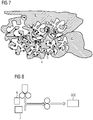
- the DE10148599 A1 and EP0115845B1 describe a similar process in which the powder mixture is first extruded into a skin or film, which is pressed onto the net in a further step, as in, for example Fig. 8 is shown schematically, the catalyst material 6 being placed on the mesh 7 in a two-stage calendering process and being calendered to form the gas diffusion electrode GDE.
- the EP2410079A2 describes the one-step process for the production of a silver-based oxygen-consuming electrode with the addition of metal oxide additives such as TiO 2 , Fe 3 O 4 , Fe 2 O 3 , NiO 2 , Y 2 O 3 , Mn 2 O 3 , Mn 5 O 8 , WO 3 , CeO 2 , Spinels such as CoAl 2 O 4 , Co (AlCr) 2 O 4 , inverse spinels such as (Co, Ni Zn) 2 (Ti, Al) O 4 , and perovskites such as LaNiO 3 , ZnFe 2 O 4 .
- metal oxide additives such as TiO 2 , Fe 3 O 4 , Fe 2 O 3 , NiO 2 , Y 2 O 3 , Mn 2 O 3 , Mn 5 O 8 , WO 3 , CeO 2 , Spinels such as CoAl 2 O 4 , Co (AlCr) 2 O 4 , inverse spinels such as (Co,
- Catalysts which can be used alternatively for the oxygen-consuming electrodes, such as noble metals, e.g. Pt, Rh, Ir, Re, Pd, noble metal alloys, e.g. Pt-Ru, compounds containing noble metals, e.g. sulphides and oxides containing noble metals, and Chevrel phases, e.g. Mo 4 Ru 2 Se 8 or Mo 4 Ru 2 S 8 , which can also contain Pt, Rh, Re, Pd, etc.
- noble metals e.g. Pt, Rh, Ir, Re, Pd
- noble metal alloys e.g. Pt-Ru
- compounds containing noble metals e.g. sulphides and oxides containing noble metals
- Chevrel phases e.g. Mo 4 Ru 2 Se 8 or Mo 4 Ru 2 S 8 , which can also contain Pt, Rh, Re, Pd, etc.
- Known Cu-based gas diffusion electrodes for generating hydrocarbons on the basis of CO 2 are, for example, in the work by R. Cook [J. Electrochem. Soc., Vol. 137, No. 2, 1990 ], where a wet chemical process based on a PTFE 30B (suspension) / Cu (OAc) 2 / Vulkan XC 72 mixture is mentioned.
- the method describes how a hydrophobic conductive gas transport layer is applied using three coating cycles and a catalyst-containing layer is applied using three additional coatings. After each layer application, there is a drying phase (325 ° C) followed by a static pressing process (1000-5000 psi).
- the calendering methods described lead to highly porous single-layer electrodes, which are characterized by low flow resistances or low bubble formation points of approx. 5-20 mbar. Due to the high porosity (50-70%) or the large pore opening radii, which are caused by such a manufacturing method, the electrodes prepared accordingly have very narrow operating times within the CO 2 electrolysis in aqueous electrolytes.
- Electrodes with small bubble formation points react relatively strongly to pressure fluctuations, so that a regulation of the differential pressure (back pressure of the CO 2 behind the electrode) by a differential pressure regulator in a technical application is complicated, as for example in DE102013011298A1 to see, whereby a more complicated control loop with the control parameters: gas composition, pressure and volume flow may be required.
- Polyvinylbenzyl structures are mainly used as the polymer backbone. Copolymers of vinylbenzyl chloride and styrene are also described, poly (4-VBC-co-St). In addition, poly (2,6-dimethyl-1,4-phenylene oxide) is also mentioned.
- the anode and cathode are in direct contact with the membrane. The electrodes are made on the basis of catalyst-coated carbon paper (GDL) (Sigracet 35 BC). It is not an all-catalyst gas diffusion electrode. Reproduction experiments led to stability problems of the ionomer on the anode side.
- the electrodes used in the processes described are based exclusively on catalyst-coated carbon fiber GDL structures that originate from the development field of fuel cells and are usually not suitable for industrially operated electrolysis processes due to their low mechanical stability. Another disadvantage is common the soot or. Coal component, which mostly contains impurities in transition metals such as Ni, Fe, and thus the undesired formation of hydrogen is increased. The adhesion of the catalyst particles to the GDL structure is also usually insufficient, so that a significant catalyst loss occurs when the system is operated for several 100-1000 hours. A similar problem can also be observed with the renewal of membranes, since a large part of the catalyst can be lost when the GDL and membrane are separated. Gas diffusion electrodes, which are constructed according to the all-catalyst concept, have essential advantages over these methods. The applicability of the ionic connection of such electrodes to a membrane is not yet known.
- Anion-exchange membranes are known from other fields of application, such as electrodialysis, for example, but they are not catalyst-modified.
- the use of ion exchange resins in electrolysis cells is known from the field of exchanger regeneration by means of electrodeionization (EDI).
- EDI electrodeionization
- these processes differ fundamentally from the electrochemical reduction of CO 2 .
- the US 2017/012334 A1 discloses an air electrode for a metal-air battery, the air electrode comprising a separator made of a hydroxide-ion conductive inorganic solid electrolyte which is a dense ceramic material.
- gas diffusion electrodes within the electroreduction of CO 2 in aqueous electrolyte solutions is usually possible in a relatively narrow process window over a longer period of> 1000 hours.
- the anode compartment and cathode compartment are typically kept separate from one another in a CO 2 electrolyser with a cation-anion-selective membrane or a diaphragm. This prevents the gaseous valuable substances formed on the cathode and anode from mixing.
- the membranes used are practically impermeable to gases, they must be permeable to ionic charge carriers. Since the membranes commonly used are chemically solid acids, the charge transport can usually only be carried out by positively charged species such as protons or electrolyte cations (e.g.
- the missing cations in the anolyte are replaced by protons generated at the anode. This usually leads either to the evolution of acid in the anolyte, which leads to a drop in the pH, or in the case of, for example, hydroxide or carbonate electrolytes, to the neutralization of the anions. In the former case, the anolyte could be converted into pure water.
- Another problem is the migration of salts into the porous electrode itself. The electrode is not Even ion-conductive, the electrochemically active centers can only be linked to water and ion transport by partially penetrating the electrode with the liquid electrolyte.
- a known cause for the penetration of electrolyte into the pores of the electrode is the hydrostatic pressure of the water column in the electrolyte gap, which limits the technical height of the electrolytic cells.
- an increasing salt crystallization of hydrogen carbonates can be observed in the area of the side facing away from the electrolyte, which in a borderline case can lead to pore clogging, so that an undesired undersupply of the catalyst with CO 2 occurs.
- a strong penetration of the aqueous medium through the pores can be observed, which leads to a Flooding of the pore system and also contributes to a CO 2 undersupply of the catalyst.
- a stable operating state can be achieved by avoiding the borderline cases mentioned.
- One aim of the present invention is therefore to produce gas diffusion electrodes with increased bubble points and wetting pressures in order to widen the operating window of the gas diffusion electrodes and to prevent salinization or the passage of electrolyte.
- the inventors found that in cell structures with an electrolyte gap between the cathode and the membrane / diaphragm, salt precipitations occur in the gas diffusion electrode during CO 2 operation, especially at higher operating temperatures, which lead to the failure of the GDE.
- the inventors have found that in the case of cell structures without an electrolyte gap or when using an M / DEA (membrane / diaphragm electrode assembly) with a gas diffusion electrode as the cathode, it also leads to strong salt formation / excretion in electrolysis in the area of the interface between the gas diffusion electrode (Cathode) and the separator membrane / diaphragm can come, so that a stable electrolysis operation is not guaranteed. Salt formation / precipitation is also independent of whether the anode is located directly on the membrane or whether a separate electrolyte gap has been provided in the cell.
- M / DEA membrane / diaphragm electrode assembly
- anion exchange materials are used as a binder material or additive in the context of the present invention, for example to quickly dissipate or partially buffer the OH - ions so that the reaction with CO 2 and the associated formation of hydrogen carbonates can be reduced or the anion exchange resins HCO 3 - conduct themselves. Since anion exchangers contain cationic functionalities, counterions are already intrinsically present to compensate for the charge to the hydrogen carbonate ions formed, and penetration of cations into the electrode is no longer necessary. Rather, anions can be transported or displaced from the electrode.
- the anion exchange resins thus also provide a path on which, for example, hydroxide or hydrogen carbonate anions can be transported away from the cathode in the direction of the electric field, so that no further cations from the electrolyte have to be used for charge compensation, which in turn lead to crystallization of salts and thus can cause a blockade of the GDE.
- an integrated anion exchanger represents a blockade for cations, which can also counteract salt excretion. It is irrelevant here whether the electrode is completely permeated with the anion exchanger.
- the anion transport functionality in the direction of the electrolyte or in the active area of the GDE is important.
- an electrolysis cell comprising a gas diffusion electrode, comprising a metal M selected from Ag, Au, Cu, Pd, and mixtures and / or alloys and / or salts thereof, and at least one binder, as cathode, wherein the gas diffusion electrode comprises hydrophilic and hydrophobic pores and / or channels, the pores and / or channels of the gas diffusion electrode at least partially containing an ion exchange material, the ion exchange material being an anion exchange material, the anion exchange material not containing imidazolium, pyridinium and ⁇ -hydrogen containing groups.
- an ion transport material is at least partially applied to the surface of the gas diffusion electrode.
- the present invention also relates to an electrolysis system comprising the electrolysis cell according to the invention.
- a method for the electrolysis of CO 2 and / or CO is also disclosed, the electrolysis cell according to the invention being used, as well as the use of the electrolysis cell according to the invention in the electrolysis of CO 2 and / or CO.
- hydrophobic is understood to be water-repellent. According to the invention, hydrophobic pores and / or channels are therefore those which repel water. In particular, according to the invention, hydrophobic properties are associated with substances or molecules with non-polar groups.
- hydrophilic is understood to mean the ability to interact with water and other polar substances.
- the present invention relates to an electrolysis cell comprising a gas diffusion electrode comprising a metal M selected from Ag, Au, Cu, Pd and mixtures and / or alloys and / or salts thereof, and at least one binder, as cathode , the gas diffusion electrode comprising hydrophilic and hydrophobic pores and / or channels, the pores and / or channels of the gas diffusion electrode at least partially containing an ion exchange material, the ion exchange material being an anion exchange material, the anion exchange material not containing any imidazolium, pyridinium or ⁇ - Has hydrogen-containing groups.
- a gas diffusion electrode comprising a metal M selected from Ag, Au, Cu, Pd and mixtures and / or alloys and / or salts thereof, and at least one binder, as cathode
- the gas diffusion electrode comprising hydrophilic and hydrophobic pores and / or channels, the pores and / or channels of the gas diffusion electrode at least partially containing an ion exchange material, the ion exchange
- a gas diffusion electrode comprising a metal M selected from Ag, Au, Cu, Pd and mixtures and / or alloys and / or salts thereof, and at least one binder, the gas diffusion electrode having hydrophilic and hydrophobic pores and / or channels, the pores and / or channels of the gas diffusion electrode at least partially containing an ion transport material and / or at least partially applying an ion transport material to the surface of the gas diffusion electrode.
- the ion transport material can be contained at least partially in the pores and / or channels of the gas diffusion electrode.
- the ion exchange material can be at least partially contained in the pores and / or channels of the gas diffusion electrode and on the surface be applied at least partially to the gas diffusion electrode.
- the metal M can serve both as a catalyst and as an electron conductor in the gas diffusion electrode.
- the metal M is selected from Cu, Ag, Au, Pd, as well as mixtures and / or alloys and / or salts thereof.
- the metal M is preferably selected from Cu, Ag and mixtures and / or alloys and / or salts thereof, in particular Ag and / or alloys and / or salts thereof.
- the salts of the metal M represent, for example, charged compounds of the metal M in which the metal M is present as a cation, preferably as M + and / or M 2+ (in particular Cu 2+ and / or Pd 2+ ), in particular M + , and which contribute to the catalytic reduction.
- the counter ions in these salts are not particularly limited.
- the proportion of metal M in the gas diffusion electrode is not particularly limited and can be between 30 and 99.8% by weight, based on the weight of the gas diffusion electrode, preferably 40% by weight or more and 96% by weight or less, more preferably 50 % By weight or more and 92% by weight or less, more preferably 65% by weight or more and 85% by weight or less.
- the metal M in the gas diffusion electrode can be present both as elemental metal M and in cationic form, preferably as M + and / or M 2+ (in particular Cu and / or Pd), particularly preferably M + .
- the at least one binder contained in the gas diffusion electrode is not particularly limited, and two or more different binders can also be used in different layers of the electrode.
- the binder or the binder for the gas diffusion electrode, if present, is not particularly limited, and includes, for example, a hydrophilic and / or hydrophobic polymer, for example a hydrophobic polymer.
- the at least one binder can be an organic binder, for example selected from PTFE (polytetrafluoroethylene), PVDF (polyvinylenedifluoride), PFA (perfluoroalkoxy polymers), FEP (fluorinated ethylene-propylene copolymers), PFSA (perfluorosulfonic acid polymers), and mixtures thereof , especially PTFE.
- PTFE polytetrafluoroethylene
- PVDF polyvinylenedifluoride
- PFA perfluoroalkoxy polymers
- FEP fluorinated ethylene-propylene copolymers
- PFSA perfluorosulfonic acid polymers
- hydrophilic materials such as polysulfones, ie polyphenyl sulfones, polyimides, polybenzoxazoles or polyether ketones or generally polymers that are electrochemically stable in the electrolyte, such as polymerized "ionic liquids", or organic conductors such as PEDOT: PSS or PANI (champhersulfonic acid-sorted polyaniline) can also be used In this way, a suitable setting of the hydrophobic pores or channels can be achieved.
- PTFE particles with a particle diameter between 0.01 and 95 ⁇ m, preferably between 0.05 and 70 ⁇ m, more preferably between 0.1, can be used to produce the gas diffusion electrode and 40 ⁇ m, for example 0.3 to 20 ⁇ m, for example 0.5 to 20 ⁇ m, for example about 0.5 ⁇ m.
- Suitable PTFE powders include, for example, Dyneon® TF 9205 and Dyneon TF 1750.
- Suitable binder particles for example PTFE particles, can for example be approximately spherical, for example spherical, and can for example by emulsion poly merization can be established. According to certain embodiments, the binder particles are free of surfactants.
- the particle size can for example be determined according to ISO 13321 or D4894-98a and can for example correspond to the manufacturer's specifications (eg TF 9205: mean particle size 8 ⁇ m according to ISO 13321; TF 1750: mean particle size 25 ⁇ m according to ASTM D4894-98a).
- the binder can, for example, in a proportion of 0.1 to 50% by weight, for example when using a hydrophilic ion transport material, for example 0.1 to 30% by weight, preferably from 0.1 to 25% by weight, for example 0.1 to 20% by weight more preferably of 3 to 20% by weight, more preferably 3 to 10% by weight, even more preferably 5 to 10% by weight, based on the gas diffusion electrode.
- the binder has a strongly pronounced shear-thinning behavior, so that fiber formation takes place during the mixing process.
- fibers formed during manufacture should wrap around the particles without completely enclosing the surface.
- the optimal mixing time can be determined, for example, by direct visualization of the fiber formation in the scanning electron microscope.
- the at least one binder is stable at a pH of 7 and more, preferably in a strongly basic environment, for example at a pH of 9 and more, for example 10 and more.
- the metal M, the at least one binder and the anion exchange material, such as an anion exchange resin can be distributed essentially homogeneously.
- the ion exchange material is an anion transport material, for example an anion exchange resin, the anion exchange material not having any groups containing imidazolium, pyridinium and ⁇ -hydrogen.
- the ion exchange material also has a cation blocker function, that is to say it can prevent or at least reduce the penetration of cations into the gas diffusion electrode.
- an anion exchange material with firmly bound cations can represent a blockade for mobile cations through Coulomb repulsion, which can additionally counteract salt excretion, in particular within the gas diffusion electrode. It is irrelevant whether the gas diffusion electrode is completely connected to the anion exchanger is interspersed.
- the anion transport functionality in the direction of the electrolyte or in the active area of the GDE is important.
- the anion exchange material is thus at least partially on a side of the gas diffusion electrode facing an electrolyte, in particular at least partially in the pores and / or channels of the gas diffusion electrode which face an electrolyte, for example a side which is arranged opposite a gas side of the gas diffusion electrode , on which a gas such as CO 2 and / or CO is fed in or bypassed.
- a cation transport e.g. a cation exchange functionality
- a cation transport can be disadvantageous here, as it can promote hydrogen formation on the one hand, and can provide paths for cations in the electrolyte on the other hand, which can lead to salt excretion.
- anion transport by means of an anion exchange material in particular at least partially in pores and / or channels of the gas diffusion electrode, in particular on a side of the gas diffusion electrode facing an electrolyte, are illustrated below.
- an anion transport additive is not absolutely necessary for the operation of a GDE, for example an oxygen-consuming cathode, up to high current densities, for example above 500 mA / cm 2.
- Fig. 24 the basic state of a GDE, for example an oxygen-consuming cathode or a GDE for converting CO 2 and / or CO, is shown without applied voltage.
- the electrolyte 45 can here penetrate the porous catalyst, here an exemplary silver catalyst Ag, with PTFE being used here as a binding material, for example.
- All cations (eg K + ) are balanced by anions (eg HCO 3 - or SO 4 2- ), with mobile cations 51 and mobile anions 52 being shown here by way of example.
- hydroxide ions produced by way of example should now diffuse out of the gas diffusion electrode.
- the diffusion of cations should be suppressed, as otherwise salt crystallization can occur.
- the same electrode can also be used to reduce CO 2 to CO, for example.
- Analogous to the reduction of oxygen two hydroxide ions are formed during the reduction of CO 2. 2e - + CO 2 + H 2 O ⁇ 2 OH- + CO
- the CO formed diffuses out of the electrode and can be discharged with the electrolyte and / or the gas flow.
- the resulting hydroxide ions can also be transported out of the electrode by the Grotthus mechanism. This reaction is sufficient up to a certain current density (eg ⁇ 150 mA / cm 2 ) and low temperature (eg ⁇ 30 ° C) to ensure stable operation.
- Fig. 26 shows an example of the electrochemical reduction of CO 2 to CO with applied voltage with the hydroxide transport through the Grotthus mechanism.
- the equilibrium is unfavorably on the side of the hydrogen carbonate, which can no longer be generated via tunnel processes, but has to be carried out of the electrode via real transport processes, as in Fig. 27 where the summary of the chemical equilibria in the exemplary gas diffusion electrode is shown.
- the migration of cations can lead to salt excretion in the GDE or at least to the formation of permeate on the side of the GDE facing away from the electrolyte.
- the anion exchange material can be introduced into the GDE with any anion. Either it can then be exchanged for OH - or HCO 3 - before installation, for example, or an exchange can take place spontaneously during operation due to the differences in concentration to the electrolyte.
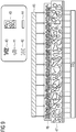
- Fig. 28 an exemplary GDE is shown, the anion exchange material 54 and catalyst, e.g. catalyst particles, eg Ag, provided with an existing binder (here, for example, PTFE) is homogeneously distributed.
- the anion exchange material contains a large number of localized positive charges 55, which can be compensated for by counter ions, for example OH - or HCO 3 -. This creates an anion path along which the anions can move. If an additional ion arises at one point in the GDE due to the electroreduction, which is not compensated at least in statu nascendi , this pushes an anion out at the phase boundary of the GDE through a hopping mechanism.
- the anion exchange material comprises polar groups such as ROR, RCOO - , R-NR 3 + , R-NH 2 , RPO 3 2- , ROH, where R is any radical, for example an organic radical.
- R is any radical, for example an organic radical.
- ion exchange resins with polar Functionalities ROR, RCOO - , R-NR 3 + , R-NH 2 , RPO 3 2- , ROH
- ROR, RCOO - , R-NR 3 + , R-NH 2 , RPO 3 2- , ROH increase the proportions of the hydrophilic areas of the electrode, whereby the electrolyte transport through the electrode can be increased.
- the dilution effect achieved can also counteract supersaturation or salt crystallization, but it should be avoided that they completely flood.
- a multilayer for example a 2-layer structure
- at least one layer does not essentially comprise the ion exchange material, for example one which faces a gas during operation, for example is therefore located on a carrier, in which case no chemical reaction should then preferably take place in this layer, which can be ensured, for example, by setting the gas pressure and / or supplying electrolyte during operation.
- the anion exchange material is stable at a pH greater than 7. According to certain embodiments, the anion exchange material is stable in a strongly basic environment, for example at a pH of 9 and more, for example 10 and more.
- the anion exchanger material is in an amount of 0.1 to 50% by weight, preferably 0.1 to 40% by weight, preferably 3 to 35% by weight, more preferably 5 to 30% by weight, even more preferably 10 Up to 25% by weight, based on the gas diffusion electrode and / or based on the layer, for example a catalyst layer in which it is contained.
- a hydrophilic or predominantly hydrophilic (eg more hydrophilic than hydrophobic areas) anion exchange material, for example anion exchange resin is preferably in an amount of 0.1 to 20% by weight, preferably 1 to 18% by weight, based on the gas diffusion electrode and / or based on the layer, for example a catalyst layer, in which it is contained.
- anion exchange materials also include hydrophobic variants of "anion exchange resins" which, as such, can usually no longer be used in aqueous media. For such, a higher amount is correspondingly possible in the gas diffusion electrode, as indicated above. If the anion exchange material is sufficiently hydrophobic, it can also act as a binder at the same time, which is preferred. The proportion of binder can then also be reduced accordingly.
- an amount of a hydrophilic or predominantly hydrophilic ion exchange material in a gas diffusion electrode is less than an amount of hydrophobic binder, and / or there is at least one layer which contains a greater amount of hydrophobic binder than of hydrophilic or predominantly hydrophilic ion exchange material.
- An undesirable penetration with electrolyte can be obtained, for example, if an amount of hydrophilic or predominantly hydrophilic anion exchange resin used exceeds the amount of hydrophobic binder used beyond the GDE.
- a ratio of more than 20% by weight of hydrophilic or predominantly hydrophilic resin to 7% by weight of PTFE has been identified as problematic.
- Such high contents of exchange resin can be achieved, for example, within the catalyst layer in the case of a two-layer GDE with an essentially hydrophobic base layer made of, for example,> 10% by weight PTFE, without a complete flow being achieved.
- the anion exchange material is added in the form of powder during production, the powder for example having a particle size of 0.1 to 100 ⁇ m, for example 1 to 50 ⁇ m, for example 1 to 20 ⁇ m or 1 to 10 ⁇ m , wherein the powder can also be macroporous, ie aggregated from the above-mentioned particles.
- the particle size can be determined, for example, microscopically by means of image analysis, laser diffraction and / or dynamic light scattering.
- a microemulsion can also be used for impregnation with ion exchange material, in which the ion exchange material can have particle sizes of 0.01 to 10 ⁇ m, e.g. 0.05 to 5 ⁇ m, e.g. 0.1 to 1 ⁇ m.
- the particle size can be determined, for example, microscopically by means of image analysis, laser diffraction and / or dynamic light scattering.
- the anion exchange material is preferably an ion transport polymer, for example also an ion exchange polymer, the polymer structure of the anion exchange material optionally also being may be partially or fully fluorinated.
- the polymer backbone of the anion exchange material is not particularly limited and can, for example, be based on a polymer or copolymer based on, for example, styrene.
- the polymer backbone can be built up, for example, from divinylbenzene-styrene copolymers which have functionalized side chains or are directly functionalized.
- the polymer backbones of the ion transport material are hydrophobic polymer structures based on PTFE (polytetrafluoroethylene), PVDF (polyvinylenedifluoride), PFA (perfluoroalkoxy polymers), FEP (fluorinated ethylene-propylene copolymers), PFSA (perfluorosulfonic acid Polymers), and mixtures thereof, in particular PTFE, possible.
- PTFE polytetrafluoroethylene
- PVDF polyvinylenedifluoride
- PFA perfluoroalkoxy polymers
- FEP fluorinated ethylene-propylene copolymers
- PFSA perfluorosulfonic acid Polymers
- the polymer backbone of the anion exchange material can serve to adjust the hydrophilic / hydrophobic properties of the gas diffusion electrode.
- hydrophilic materials such as polysulfones, e.g. polyphenyl sulfones, polyimides, polybenzoxazoles or polyether ketones or, in general, polymers that are electrochemically stable in the electrolyte, such as, for example, polymerized "ionic liquids".
- Suitable functional groups for ion transport which are also described below by way of example, can be inserted for all of the polymer backbones mentioned, for example by replacing functional groups present there with suitable leaving groups.
- the anion exchange material for example ion exchange polymer
- polar ion exchange resins in the catalyst layer leads to a noticeable increase in the hydrophilic properties of the gas diffusion electrode, so that the overall hydrophilicity can be adjusted.
- an electrolysis cell in an electrolysis cell according to the invention this is preferably in direct contact with an anion exchange membrane and / or an anion exchange diaphragm on the side facing the anode.
- All-catalyst electrodes with only one layer with ionic conductivity are preferably used in direct contact with an anion exchange membrane and / or an anion exchange diaphragm.
- no contact with a membrane and / or a diaphragm is provided here, that is to say a gap.
- the anion exchange material for example an ion exchange polymer or anion exchange resin, can comprise various functional groups for ion exchange, which can be the same or different, for example tertiary amine groups, alkylammonium groups and / or phosphonium groups. According to certain embodiments, the anion exchange material has quaternary alkyl ammonium groups.
- alkyl radicals in the alkylammonium groups are not particularly restricted and can be, for example, substituted and / or unsubstituted, linear and / or branched alkyl radicals with 1 to 40 carbon atoms, for example 1 to 20 carbon atoms, for example substituted or unsubstituted methyl , Ethyl, propyl, isopropyl, butyl, isobutyl, tert-butyl radicals, etc., especially methyl radicals.
- substituents are F and Cl, preferably F; OH, etc., preferably OH and / or F, are suitable.
- the anion exchanger material has quaternary alkylammonium groups, preferably unsubstituted ones Tetraalkylammonium groups, in particular tetramethylammonium groups, and / or dialkylethanolammonium groups in which the alkyl groups are not substituted, for example dimethylethanolammonium groups.
- the anion exchange material does not include trialkylethanol groups.
- the anion exchange material has no imidazolium, pyridinium and / or ⁇ -hydrogen-containing groups, since the chemical stability under electrolysis conditions may not be sufficient.
- Suitable ion transport polymers for example ion exchange polymers, include, especially for the electrochemical reduction of CO 2 , basic or strongly basic ion exchange resins of type I (with tetraalkylammonium groups) and / or type II (with dimethylethanolammonium groups).
- ion exchange polymers include, especially for the electrochemical reduction of CO 2 , basic or strongly basic ion exchange resins of type I (with tetraalkylammonium groups) and / or type II (with dimethylethanolammonium groups).
- Commercially available and suitable anion exchange materials are shown by way of example in Table 2 below.
- Table 2 Examples of suitable commercially available anion exchange resins Exchange resin Resin type matrix functional group DOWEX Monosphere 550A strongly basic Styrene DVB GEL Tetraalkylammonium DOWEX Monosphere 700A strongly basic Styrene DVB GEL Tetraalkylammonium DOWEX Monosphere MP-725A strongly basic Styrene DVB macroporous Tetraalkylammonium DOWEX SBR-C strongly basic Styrene DVB Tetraalkylammonium DOWEX SBR-LC NG strongly basic Styrene DVB Tetraalkylammonium Lewatit Monoplus M500 strongly basic Styrene DVB GEL Tetraalkylammonium Lewatit Monoplus Mp500 strongly basic Styrene DVB macroporous Tetraalkylammonium Lewatit Monoplus Mp500 OH strongly basic Styrene DVB macroporous Tetraalkylammonium Lewatit Monoplus Mp500 KR strongly basic Styrene DVB
- ionomers can also be used as anion exchange materials, which can be used, for example, in the form of a dispersion during production.
- the ionomers can also be based on quaternary ammonium functionalities.
- Known ionomers are available here, for example, from Tokuyama, type AS 4, which is also based on quaternary ammonium functionalities.
- the ionomers here for example, have a lower molecular weight than the resins, but are essentially chemically similar. As a result of the lower molecular weight, the lower molecular weight ionomers are usually also more readily soluble than the corresponding resins.
- the anion exchange material such as an anion exchange resin
- the anion exchange material is at least partially fluorinated.
- the anion exchange material has side chains which are fluorinated, are at least partially fluorinated, for example are completely fluorinated.
- the anion exchange material furthermore has OH groups and / or NH 2 groups.
- the ion transport material for example an ion exchange resin, can thereby itself be co-catalytically active in that CO 2 is actively bound by R-NH 2 or R-OH functions.
- the anion exchange material is not chemically changed during the production process, for example by the mixing process and / or the presence of the metal M, for example as a catalyst. However, it can be deformed mechanically, for example into fibers.
- the electrode is a gas diffusion electrode.
- the gas diffusion electrode is not particularly limited in terms of its design, as long as it is in the case of gas diffusion electrodes Usually three physical states - solid, liquid and gaseous - can be in contact with one another and the solid of the electrode has at least one electron-conducting catalyst which can catalyze an electrochemical reaction between the liquid and the gaseous phase.
- the gas diffusion electrodes can be operated in a flow-by as well as a flow-through configuration, that is, a gas flows behind or flows through them, but preferably flows behind them. It is also not excluded that a gas diffusion electrode is not completely porous, but only has a structure on the surface through which a gas can diffuse, for example a micro- and / or nanostructuring.
- hydrophobic channels and / or pores or areas and possibly hydrophilic channels and / or pores or areas in the gas diffusion electrode (GDE) on the electrolyte side it being possible for catalyst centers to be located in the hydrophilic areas.
- GDE gas diffusion electrode
- the gas diffusion electrode can comprise at least two sides, one with hydrophilic and possibly hydrophobic areas and one with hydrophobic areas.
- Particularly active catalyst centers are in a GDE in the three-phase area liquid, solid, gaseous.
- An ideal GDE thus has a maximum penetration of the bulk material with hydrophilic and hydrophobic channels and / or pores in order to obtain as many three-phase regions as possible for active catalyst centers.
- the gas diffusion electrode comprises or consists of metal M, the anion exchange material, and the binder.
- Fig. 7 illustrates the relationships between hydrophilic and hydrophobic areas of a GDE with two layers, one can achieve good three-phase relationship liquid, solid, gaseous.
- the electrode on the electrolyte side E there are hydrophobic channels or areas 1 and hydrophilic channels or areas 2, it being possible for catalyst centers 3 of low activity which can be provided by the compound of the metal M to be located in the hydrophilic areas 2.
- catalyst centers 3 of low activity which can be provided by the compound of the metal M to be located in the hydrophilic areas 2.
- there are inactive catalyst centers 5 on the side of the gas G which have no access to the electrolyte.
- Particularly active catalyst centers 4 are liquid, solid, gaseous in the three-phase region.
- An ideal GDE can thus have a maximum penetration of the bulk material with hydrophilic and hydrophobic channels in order to obtain as many three-phase regions as possible for active catalyst centers.
- gas diffusion electrodes with only one layer are also included, as long as the gas diffusion electrode comprises the metal M, the at least one binder and the at least one anion exchange material.
- the hydrophilic and hydrophobic areas e.g. pores and / or channels, can then also be present in one layer, so that predominantly hydrophilic and predominantly hydrophobic areas can arise in the layer.
- the explanation of the catalyst centers is then analogous to the two-layer structure shown as an example.
- the ion transport material can be in both layers. However, the side facing the electrolyte is particularly preferred.
- an anion exchange material advantageously transports anions, preferably generated in the GDE, away from the gas side and in the direction of the electrolyte, while the anion exchange material can also prevent the cations of the electrolyte from penetrating the GDE.
- the gas diffusion electrode has pores and / or channels with a diameter of 10 nm to 100 ⁇ m, preferably from 50 nm to 50 ⁇ m, more preferably from 100 nm to 10 ⁇ m, which can be demonstrated, for example, by scanning electron microscopy, possibly after previous cutting GDE, can be determined.
- the catalyst of the present GDE which comprises the metal M and cations thereof, preferably M + and / or M 2+ (the latter in particular for Pd and / or Cu), in particular M + , can also have dendritic structures with a fine structure, for example a spacing between two dendrites, with a size of 1 to 100 nm, preferably 2 to 20 nm, more preferably 3 to 10 nm.
- the electrode according to the invention can also comprise further components, for example a substrate or a carrier to which the metal M, the at least one binder and optionally the anion exchange material can be applied.
- a substrate or a carrier to which the metal M, the at least one binder and optionally the anion exchange material can be applied.
- the anion exchange material it can also be the case that a first layer is applied to the carrier which does not have any anion exchange material, the anion exchange material then being contained in a second, third, etc. layer.
- the carrier is not particularly restricted and can include, for example, a metal such as silver, platinum, nickel, lead, titanium, nickel, iron, manganese, copper or chromium or their alloys such as stainless steels and / or at least one non-metal such as carbon , Si, boron nitride (BN), boron-doped diamond, etc., and / or at least one conductive oxide such as indium tin oxide (ITO), aluminum zinc oxide (AZO) or fluorinated tin oxide (FTO) - for example for the production of photoelectrodes, and / or at least one polymer based on polyacetylene, polyethoxythiophene, polyaniline or polypyrrole, such as in polymer-based electrodes.
- a metal such as silver, platinum, nickel, lead, titanium, nickel, iron, manganese, copper or chromium or their alloys such as stainless steels and / or at least one non-metal such as carbon , Si,
- Non-conductive supports such as polymer networks are possible, for example, if the conductivity of the catalyst layer is sufficient. Larger if there is sufficient conductivity 0.01 m / ohm ⁇ mm 2 and correspondingly resolved rear-side contacting of the electrode, for example by means of a titanium expanded metal grid, polymer supports or nets are also possible.
- the carrier can essentially be formed by the metal M, optionally with at least one binder.
- a preferred carrier is a mesh with a mesh size w of 0.3 mm ⁇ w ⁇ 2.0 mm, preferably 0.5 mm ⁇ w ⁇ 1.4 mm and a wire diameter x of 0.05 mm ⁇ x ⁇ 0.5 mm, preferably 0.1 mm x 0.25 mm.
- the first layer can also contain further promoters which, in cooperation with the metal M, improve the catalytic activity of the GDE.
- the first layer contains at least one metal oxide which preferably has a lower reduction potential than the evolution of ethylene, preferably ZrO 2 , Al 2 O 3 , CeO 2 , Ce 2 O 3 , ZnO 2 , MgO; and / or at least one metal-rich (based on M), for example copper-rich and / or silver-rich, intermetallic phase, for example a Cu-rich phase, which is selected from the group of binary systems Cu-Al, Cu-Zr, Cu-Y, Cu-Hf, Cu-Ce, Cu-Mg and the ternary systems Cu-Y-Al, Cu-Hf-Al, Cu-Zr-Al, Cu-Al-Mg, Cu-Al-Ce with Cu contents> 60 At .-%, and or a corresponding Ag-rich phase such as Ag-Al, Ag-Zr,
- Suitable promoters are also compounds of the metal M which have a solubility in water at 25 ° C. and normal pressure of less than 0.1 mol / l, preferably less than 0.05 mol / L, more preferably less than 0.01 mol / L, even more preferably less than 0.0001 mol / L, particularly preferably less than 1 * 10 -10 mol / L, for example less than 1 * 10 -20 mol / L.
- Such solubilities of compounds of the metal M can be taken, for example, from product data sheets and / or in a simple manner with simple experiments, e.g. placing a fixed amount of the compound of the metal M in a certain volume of water, e.g. distilled, double-distilled or triple-distilled water at 25 ° C and normal pressure and measurement of the concentration of ions released from the compound over the time until an approximately constant value has been reached, and are therefore easily accessible to the person skilled in the art.
- the compound of the metal M which has a solubility in water at 25 ° C. and atmospheric pressure of less than 0.1 mol / L, can have a formula which is selected from M 1-x X, M 2-y Y, M 2-y Y ' w and M 3-z Z, where 0 x 0.5; 0 ⁇ y ⁇ 1; 0 ⁇ z ⁇ 1.5; preferably 0 x 0.4; 0 ⁇ y ⁇ 0.8; 0 z 1.2; more preferably 0 x 0.3; 0 ⁇ y ⁇ 0.6; 0 ⁇ z ⁇ 0.9; X is selected from Cl, Br, Br 3 , I, I 3 , P 3 , As 3 , As 5 , AS 7 , Sb 3 , Sb 5 , Sb 7 , and mixtures thereof, for example Cl, Br, Br 3 , I , I 3 , P 3 , and mixtures thereof; Y is selected from S, S, Te, and mixtures thereof; Y 'is selected from S, Se, Te and mixtures thereof,
- Z is selected from P, As, Sb, Bi, P 3 , As 3 , As 5 , AS 7 , Sb 3 , Sb 5 , Sb 7 , and mixtures thereof, e.g., P, As, Sb, Bi, and mixtures thereof ; and / or is selected from molybdates, tungstates, selenates, arsenates, vanadates, chromates, manganates, niobates of the metal M and thio and / or seleno derivatives of molybdates, tungstates, selenates, arsenates, vanadates, chromates, manganates, niobates of the Metal M; and / or compounds of the formula M a X b Y c Z d , where a 2, for example a; 3; 0 b 4, for example 0 b 3, for example 0 b 2, for example 0 b 1; 0 ⁇ c
- X is selected from Cl, Br, Br 3 , I, I 3 , P 3 , As 3 , As 5 , AS 7 , Sb 3 , Sb 5 , Sb 7 , and mixtures thereof, for example Cl, Br, Br 3 , I , I 3 , P 3 , and mixtures thereof;
- Y selected is made up of S, S, Te, and mixtures thereof;
- Z is selected from P, As, Sb, Bi, P 3 , As 3 , As 5 , AS 7 , Sb 3 , Sb 5 , Sb 7 , and mixtures thereof, wherein at least two of b and c are not 0 at the same time.
- the compound of the metal M which has a solubility in water at 25 ° C. and normal pressure of less than 0.1 mol / L, does not have to be stoichiometric here either and can also have mixed phases.
- Ternary, quaternary, etc. compounds such as, for example, Ag 3 SbS 3 , pyrargyrite, or Ag 3 AsS 3 , xanthoconite are also included.
- the compound of the metal M which has a solubility in water at 25 ° C. and atmospheric pressure of less than 0.1 mol / L, is a compound of the formula Ia: M 1-x X, where 0 x 0 , 5; preferably 0 x 0.4; more preferably 0 x 0.3 and X is selected from Cl, Br, Br 3 , I, I 3 , P 3 , As 3 , As 5 , AS 7 , Sb 3 , Sb 5 , Sb 7 , and mixtures thereof , e.g. Cl, Br, Br 3 , I, I 3 , P 3 , and mixtures thereof, e.g. also mixtures of Cl, Br, I, e.g.
- the latter compounds of silver in particular are partially photosensitive. However, this is usually irrelevant for operation, since the electrodes in the electrolyser are not exposed to daylight.
- the compound Ia are, for example, AgCl, AgBr, AgI, AgP 3 , CuCl, CuBr, CuI, AuCl, AuBr, AuI.
- the compound of the metal M which has a solubility in water at 25 ° C. and normal pressure of less than 0.1 mol / L, is a chalcogen-based compound of the formula Ib: M 2-y Y, or I *: M 2-y Y ' w , where 0 ⁇ y ⁇ 1; preferably 0 y 0.8; more preferably 0 y 0.6; Y is selected from S, S, Te, and mixtures thereof; Y 'is selected from S, Se, Te and mixtures thereof, for example S, Se and mixtures thereof, for example S, Se; and w ⁇ 2, preferably w ⁇ 10, e.g. w ⁇ 5, e.g.
- the polymeric or oligomeric anions of sulfur or selenium are Y ' w 2 -. These compounds are partially semiconducting, so that an electrical coupling to the silver catalyst can be guaranteed.
- Substoichiometric compounds with 0 ⁇ y ⁇ 1; preferably 0 ⁇ y 0.8; more preferably 0 ⁇ y 0.6; e.g. 0 ⁇ x ⁇ 0.4; 0 ⁇ x ⁇ 0.2; 0 ⁇ x 0.1 are also suitable.
- y 0.
- Examples of the compound of the formula Ib are, for example, Ag 2 S, Ag 2 Se, Ag 2 Te, Cu 2 S, Cu 2 Se, Cu 2 Te, Au 2 S, and examples of the compound of the formula I'b e.g. Ag 2 (S 2 ), Ag 2 (Se 2 ), Cu 2 (S 2 ), Cu 2 (Se 2 ), etc.
- the compound of the metal M which has a solubility in water at 25 ° C. and atmospheric pressure of less than 0.1 mol / L, is a compound of the formula Ic: M 3-z Z, where 0 z 1 1 , 5; preferably 0 z 1.2; more preferably 0 z 0.9; and Z is selected from P, As, Sb, Bi, P 3 , As 3 , As 5 , AS 7 , Sb 3 , Sb 5 , Sb 7 , and mixtures thereof, e.g.
- These connections are partially semiconducting or metallically conductive, so that an electrical coupling to the silver catalyst can be guaranteed.
- Substoichiometric compounds with 0 ⁇ z ⁇ 1.5; preferably 0 ⁇ z 1.2; more preferably 0 ⁇ z 0.9; for example 0 ⁇ x;0.6; 0 ⁇ x ⁇ 0.4; 0 ⁇ x ⁇ 0.2; 0 ⁇ x 0.1 are also suitable.
- z 0.
- Examples of the compound of the formula Ic are, for example, Ag 3 P, Ag 3 As, Ag 3 Sb, Ag 3 Bi, Cu 3 P, Cu 3 As, Cu 3 Sb, Cu 3 Bi.
- compounds of the metal M which have a solubility in water at 25 ° C. and normal pressure of less than 0.1 mol / L with heavy anions such as molybdate, tungstate, arsenate, selenate, vanadate, chromate, manganate are also included niobate or thio and / or seleno derivatives thereof in various oxidation states.
- heavy anions such as molybdate, tungstate, arsenate, selenate, vanadate, chromate, manganate
- These anions can also be present in polymer form in the form of polyoxometalates. These are then mainly used in the form of their silver salts.
- mineral compounds of the metal M for example of the formula M a X b Y c Z d , where a horizoni 2, for example a 3; 0 b 4, for example 0 b 3, for example 0 b 2, for example 0 b 1; 0 ⁇ c ⁇ 8, e.g. 0 ⁇ c ⁇ 6, e.g. 0 ⁇ c ⁇ 5, e.g. 0 ⁇ c ⁇ 4, e.g. 0 ⁇ c ⁇ 3, e.g. 0 ⁇ c ⁇ 2, e.g. 0 ⁇ c ⁇ 1; 0 ⁇ 4, e.g. 0 ⁇ d ⁇ 3, e.g. 0 ⁇ d ⁇ 2, e.g.
- X is selected from Cl, Br, Br 3 , I, I 3 , P 3 , As 3 , As 5 , AS 7 , Sb 3 , Sb 5 , Sb 7 , and mixtures thereof, for example Cl, Br, Br 3 , I , I 3 , P 3 , and mixtures thereof;
- Y is selected from S, S, Te, and mixtures thereof;
- Z is selected from P, As, Sb, Bi, P 3 , As 3 , As 5 , AS 7 , Sb 3 , Sb 5 , Sb 7 , and mixtures thereof, e.g., P, As, Sb, Bi, and mixtures thereof , where at least two of b and c are not 0 at the same time, for example Ag 3 SbS 3 , pyrargyrite, or Ag 3 AsS 3 , xanthoconite.
- the compounds of the metal M mentioned in the context of the invention which have a solubility in water at 25 ° C. and atmospheric pressure of less than 0.1 mol / L, can occur in different modifications which can differ in their crystal structure.
- the following ternary compounds are also known, for example: Ag 3 SbS 3 , pyrargyrite, Ag 3 AsS 3 , xanthoconite, which can be used in gas diffusion electrodes according to the invention.
- Preferred promoters here are metal oxides and / or compounds of the metal M which have a solubility in water at 25 ° C. and normal pressure of less than 0.1 mol / l.
- the metal oxide used and / or the compound of the metal M which has a solubility in water at 25 ° C and normal pressure of less than 0.1 mol / L is, according to certain embodiments, water-insoluble, so that aqueous electrolytes can be used in an electrolysis using the gas diffusion electrode according to the invention.
- the redox potential of the metal oxide is lower than that of the evolution of ethylene, it can be ensured that ethylene can be produced from CO 2 by means of the GDE according to the invention.
- the oxides should also not be reduced in the event of a carbon dioxide reduction. Nickel and iron, for example, are unsuitable because hydrogen is formed here.
- the metal oxides are preferably not inert, but should preferably represent hydrophilic reaction centers which can serve to provide protons.
- the promoters in particular the metal oxide and / or the compound of the metal M, which has a solubility in water at 25 ° C. and normal pressure of less than 0.1 mol / L, can promote the function and production of long-term stable electrocatalysts by Stabilize catalytically active metal (M) nanostructures, eg of Cu and / or Ag.
- M catalytically active metal
- the structural promoters can reduce the high surface mobility of the nanostructures and thus their tendency to sinter.
- metal oxide-metal M catalyst structures which are produced as follows, metal oxides of the metal M being used in the production.
- LDHs Layered double hydroxides
- the corresponding precursors can be added by co-dosing a Metal salt solution and a basic carbonate solution pH controlled precipitated.
- a special feature of these materials is the presence of particularly fine metal M crystallites with a size of 4-10 nm, which can be structurally stabilized by an oxide of the metal M present.
- the metal oxide Due to its high specific surface, the metal oxide can lead to better distribution of the catalyst metal M; highly dispersed metal centers can be stabilized by the metal oxide; a gas such as CO 2 chemisorption can be enhanced by the metal oxide; Metal oxides of the metal M, for example Cu, Ag, can be stabilized.
- oxide precursors and activated precursors can also be mixed in some cases.
- the finished calendered electrode is subjected to a subsequent calcination / thermal treatment before the electrochemical activation is carried out.
- Another possibility for producing suitable electrocatalysts is based on the approach of producing intermetallic phases rich in metal M, such as Cu 5 Zr, CU 10 Zr 7 , Cu 51 Zr 14 , Ag 5 Zr, Ag 10 Zr 7 , Ag 51 Zr 14 , which suffice the melt can be produced.
- Corresponding ingots can subsequently be ground and completely or partially calcined in an O 2 / argon gas stream and converted into the oxide form.
- phases rich in metal M are binary systems Cu-Al, Cu-Zr, Cu-Y, Cu-Hf, Cu-Ce, Cu-Mg and corresponding ternary systems with metal M contents> 60at%: CuYAl, CuHfAl, CuZrAl , CuAlMg, CuAlCe and or corresponding Ag-rich phases such as Ag-Al, Ag-Zr, Ag-Y, Ag-Hf, Ag-Ce, Ag-Mg, Ag-Y-Al, Ag-Hf-Al, Ag- Zr-Al, Ag-Al-Mg, Ag-Al-Ce with Ag contents ⁇ 60 at .-%.
- Copper-rich phases, for example, are off E. Kneller, Y.
- the proportion of metal M, for example Cu, Ag is preferably greater than 40 at.%, More preferably greater than 50 at.%, Particularly preferably greater than 60 at.%.
- the intermetallic phases also contain non-metal elements such as oxygen, nitrogen, sulfur, selenium and / or phosphorus, for example oxides, sulfides, selenides, nitrides and / or phosphides, arsenides, antimonides, bismuthides. According to certain embodiments, the intermetallic phases are partially oxidized.
- the following copper-containing perovskite structures and / or defect perovskites and / or perovskite-related compounds can be used for electrocatalysts, in particular for the formation of CO or hydrocarbons: YBa 2 Cu 3 O 7-, ⁇ , where 0 ⁇ ⁇ 1, CaCu 3 Ti 4 O 12 , La 1 , 85 Sr 0.15 , CuO 3.930 Cl 0.053 , (La, Sr) 2 CuO 4 , AgTaO 3 or lithium-modified Ag 1-x Li x NbO 3 . Furthermore, it is not ruled out that mixtures of these materials can be used for electrode preparation or that subsequent calcination or activation steps can be carried out as required.
- the inventors have also found that particularly active and CO or C 2 H 4 -selective gas diffusion electrodes for CO 2 and / or CO electrolysis should meet a large number of parameters that are advantageous for selective product formation.
- invention-specific properties of certain embodiments of an electrode according to the invention are shown.
- specific embodiments of the catalyst are advantageous in order that the electrode can selectively form products.
- all the particles contained should be part of the three-phase boundary in order to be able to achieve high current densities.
- the pore system should, in particular for copper, have sufficient absorption of intermediate products in order to ensure further reaction or dimerization / oligomerization.
- the gas diffusion electrode comprises a carrier, preferably in the form of a flat structure, and a layer comprising the metal M, the ion exchange material and at least one binder, the layer comprising hydrophilic and hydrophobic pores and / or channels, the proportion by weight of the ion exchange material in the layer being preferably greater than the proportion by weight of the binder.
- the gas diffusion electrode comprises a carrier, preferably in the form of a flat structure, a first layer comprising the metal M, the ion exchange material and optionally at least one binder, the first layer comprising hydrophilic and optionally hydrophobic pores and / or channels, and furthermore a second layer comprising the metal M and at least one binder, the second layer being on the carrier and the first layer on the second layer, the content of binder in the first layer being preferred is smaller than in the second layer, wherein the second layer comprises hydrophobic pores and / or channels, more preferably wherein the second layer 3 - 30 wt.% binder, preferably 4 - 28 wt.% binder, more preferably 5 - 20 wt.
- % e.g. 10-20% by weight of binder, based on the second layer, and the first layer preferably 0-20% by weight of binder, more preferably 0.1-15% by weight of binder, more preferably 1 to 12% by weight Binder, even more preferably 5-10% by weight of binder (e.g. PTFE), and / or 0.1-40% by weight of ion exchange material, preferably 1-35% by weight of ion exchange material, more preferably 3-30% by weight of ion exchange material, e.g. 10-25% by weight of ion exchange material, based on the first layer.
- binder e.g. PTFE
- ion exchange material preferably 1-35% by weight of ion exchange material, more preferably 3-30% by weight of ion exchange material, e.g. 10-25% by weight of ion exchange material, based on the first layer.
- the proportion of metal M, binder and ion exchange material can each add up to 100% by weight. It is not excluded here that the second layer contains an ion exchange material; however, the second layer, which faces the gas side, preferably contains no ion exchange material, for example anion exchange material.
- the electrolytic cell according to the invention further comprises an anode and at least one membrane and / or at least one diaphragm between the cathode and anode, for example at least one anion exchange membrane.
- the further components of the electrolysis cell such as the anode, possibly a membrane and / or a diaphragm, supply line (s) and discharge line (s), the voltage source, etc., as well as other optional devices such as cooling or heating devices are not particularly limited according to the invention, as well as non-anolytes and / or catholytes which are used in such an electrolytic cell, the electrolytic cell being used according to certain embodiments on the cathode side for the reduction of carbon dioxide and / or CO.
- the design of the anode space and the cathode space is also not particularly restricted.
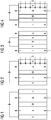
- FIG Figures 1 to 4 and 29 First exemplary configurations for an exemplary structure of general electrolysis cells and possible anode and cathode spaces are shown in FIG Figures 1 to 4 and 29 shown.
- An electrochemical reduction of, for example, CO 2 and / or CO takes place in an electrolysis cell, which usually consists of an anode and a cathode compartment.
- an electrolysis cell which usually consists of an anode and a cathode compartment.
- a described gas diffusion electrode can be used for each of these cell arrangements, for example as a cathode.
- membranes M for separating catholyte and anolyte shown but which can also be supplemented or replaced by diaphragms, for example.
- An example is the cathode compartment II in Figure 1 designed in such a way that a catholyte is fed in from below, which leaves the cathode compartment II towards the top.
- the catholyte can also be fed in from above, as is the case with falling film electrodes, for example.
- CO 2 and / or CO can be supplied via the gas diffusion electrode K.
- a substance is oxidized in the anode compartment I, which is supplied from below, for example with an anolyte, and the anolyte with the product the oxidation then leaves the anode compartment.
- This 2-chamber structure differs from the 3-chamber structure in Figure 2 to the effect that a reaction gas such as carbon dioxide or CO can be conveyed through a porous gas diffusion electrode as the cathode into the cathode space II for reduction.
- a reaction gas such as carbon dioxide or CO
- a porous gas diffusion electrode as the cathode into the cathode space II for reduction.
- a porous anode are also conceivable.
- the rooms I and II are separated by a membrane M.
- the Figure 3 a porous cathode K and a porous anode A directly on the membrane M, whereby the anode compartment I is separated from the cathode compartment II.
- the structure in Figure 4 corresponds to a hybrid form from the structure Figure 2 and the structure Figure 3 , a structure with a gas diffusion electrode being provided on the catholyte side, as in FIG Figure 2 shown, whereas on the anolyte side a structure as in Figure 3 is provided.
- a structure with a gas diffusion electrode being provided on the catholyte side, as in FIG Figure 2 shown, whereas on the anolyte side a structure as in Figure 3 is provided.
- mixed forms or other configurations of the electrode spaces shown by way of example are also conceivable.
- Embodiments without a membrane are also conceivable.
- the cathode-side electrolyte and the anode-side electrolyte can thus be identical, and the electrolysis cell / electrolysis unit can do without a membrane. Sufficient gas separation can then be achieved, for example, by appropriate construction of the electrolytic cell.
- the electrolytic cell in such embodiments has a membrane and / or a diaphragm or several membranes and / or diaphragms, for example 2, 3, 4, 5, 6 or more membranes and / or diaphragms, which are the same or different can, but this is possibly associated with additional effort in terms of the membrane as well as the applied voltage.
- the catholyte and anolyte can optionally be mixed again outside the electrolysis cell.
- Figures 1 to 4 are schematic representations.
- the electrolytic cells off Figures 1 to 4 can also be combined to form mixed variants.
- the anode compartment can be used as a PEM half-cell, as in FIG Figure 3
- the cathode compartment consists of a half-cell that contains a certain volume of electrolyte between the membrane and the electrode, as in Figure 1 shown.
- the electrolytic cell according to the invention then also one like in Fig. 29 may have the structure shown.
- the CO 2 can then diffuse through the gas diffusion electrode and reach the catholyte.
- the distance between the electrode and the membrane and / or diaphragm is very small or 0 if the membrane and / or the diaphragm is made porous and includes a supply of the electrolyte.
- the membrane and / or the diaphragm can also have a multilayer design so that separate feeds of anolyte and catholyte are made possible.
- separation effects can be achieved, for example, through the hydrophobicity of intermediate layers and / or a corresponding adjustment of the prevailing capillary forces. Conductivity can still be guaranteed if conductive groups are integrated in such separating layers.
- the membrane and / or the diaphragm can be an ion-conducting membrane and / or an ion-conducting diaphragm, or a separator which only effects mechanical separation and is permeable to cations and anions.
- the electrode is a gas diffusion electrode that enables a three-phase electrode to be built up.
- a gas can be fed from behind to the electrically active front side of the electrode in order to carry out the electrochemical reaction there.
- the gas diffusion electrode can only flow behind, ie a gas such as CO 2 and / or CO is led past the rear of the gas diffusion electrode in relation to the electrolyte, the gas then being able to penetrate through the pores of the gas diffusion electrode and the product being carried away at the rear can. It was found that even though a gas such as CO 2 does not "bubble" through the electrolyte, similarly high Faraday efficiencies (FE) can be found on products.
- FE Faraday efficiencies
- the gas flow when flowing behind is preferably also the reverse of the flow of the electrolyte, so that any liquid that may have been forced through is transported away can be.
- a gap between the gas diffusion electrode and the membrane is advantageous as an electrolyte reservoir.
- the supply of a gas can also be used in other ways for the in Figure 3 accomplish shown gas diffusion electrode, for example when supplying CO 2 . Because the gas, for example CO 2 , is passed through the electrode in a targeted manner, the reduction products can in turn be quickly discharged.
- the electrolytic cell has a membrane and / or a diaphragm which separates the cathode compartment and the anode compartment of the electrolytic cell in order to prevent the electrolytes from mixing.
- the membrane and / or the diaphragm is not particularly limited here, provided that it separates the cathode compartment and the anode compartment. In particular, it essentially prevents the gases produced at the cathode and / or anode from flowing over to the anode or cathode compartment.
- a preferred membrane is an ion exchange membrane, for example based on polymers.
- a preferred material of an ion exchange membrane is a sulfonated tetrafluoroethylene polymer such as Nafion®, for example Nafion® 115.
- a sulfonated tetrafluoroethylene polymer such as Nafion®, for example Nafion® 115.
- ceramic membranes can also be used, for example those in EP 1685892 A1 polymers mentioned and / or loaded with zirconium oxide, for example polysulfones.
- At least one membrane and / or at least one diaphragm in particular at least one anion exchange membrane (eg Tokuyama A201) and / or an anion exchange diaphragm, is not in contact with the anode.
- at least one further membrane and / or another diaphragm is provided between an anion exchange membrane and / or an anion exchange diaphragm and the anode, for example a cation exchange membrane and / or a cation exchange diaphragm, e.g. a Nafion®-based membrane, an electrolyte spar is then preferably provided in between here.
- the electrolytic cell according to the invention comprises 2 or more, e.g. 3, 4, 5, 6 or more membranes and / or diaphragms, with electrolyte spaces being provided between the various membranes and / or diaphragms and / or the membranes and / or diaphragms and the electrodes could be.
- the electrolysis cell according to the invention comprises at least one anion exchange membrane and / or one anion exchange diaphragm and at least one cation exchange membrane and / or one cation exchange diaphragm.
- the cation exchange membrane and / or the cation exchange diaphragm is in direct contact with the anode.
- an anion exchange membrane and / or an anion exchange diaphragm is in direct contact with the gas diffusion electrode according to the invention, which is connected as a cathode.
- An ionic connection of the GDE to an anion exchange membrane and / or an anion exchange diaphragm in a zero-gap arrangement can be ensured by using anion transport resins or ionomers. This step is advantageous for this mode of operation, since otherwise increased salt formation can be observed in the area of the boundary layer between GDE and anion exchange membrane, which can ultimately lead to complete isolation of the GDE.
- the material of the anode is not particularly limited and depends primarily on the desired reaction.
- exemplary anode materials include platinum or platinum alloys, palladium or palladium alloys, and vitreous carbon.
- Other anode materials are also conductive oxides such as doped or undoped TiO 2 , indium tin oxide (ITO), fluorine-doped tin oxide (FTO), aluminum-doped zinc oxide (AZO), iridium oxide, etc. If necessary, these catalytically active compounds can only be used in thin-film technology be applied superficially, for example on a titanium and / or carbon carrier.
- FIGS. 11 to 14 For the use of gas diffusion electrodes produced with ion exchange material, in particular with anion exchange resin and / or ionomer, the in FIGS. 11 to 14 Operating modes shown are possible, with diaphragms also being able to be provided here, in accordance with certain embodiments, instead of membranes.
- FIGs 11-14 In principle, two cell variants are shown for electrolysis cells: All cell variants use a GDE all-round catalyst with a single-layer structure, e.g. rolled onto a mesh, which was manufactured or impregnated with an anion exchange resin or ionomer as the anion exchange material and which is in direct contact with the AEM. In all cases, gaseous CO 2 is fed in from the rear of the GDE without a complete passage, which can also be seen as a flow by variant. In the cells shown, as well as generally in a reduction method according to the invention, a gas such as CO 2 and / or CO can be humidified before it reaches the GDE.
- a gas such as CO 2 and / or CO can be humidified before it reaches the GDE.
- anode When designing the anode, it is advantageous to avoid direct contact with an anion exchange membrane M1 because of observed stability problems. This applies to both the CCM execution in Fig. 14 , in which the anode catalyst, for example an IrOx catalyst, is pressed directly into the membrane M2, as well as for the use of a dimensionally stable anode A1, which can consist, for example, of an IrOx-coated expanded titanium metal.
- the gap between the anode and the GDE (cathode) should advantageously be as small as possible in order to achieve the highest possible efficiency of the system.
- the operating mode shown describes the diffusion operation of the gas diffusion electrode, whereby gaseous starting materials (here CO 2 ) and products P can be provided via the rear side of the electrode without these passing through the electrode.
- the gas pressure used should advantageously be selected as a function of the "bubble point" (eg range from 1-50 mbar) of the GDE electrode so that no gas can pass through.
- An advantage of this mode of operation is a higher conversion of the CO 2 used in contrast to the flow-through variant.
- the gas diffusion electrode described is particularly suitable for this cell operation.
- the manufacturing technique described can represent the basis for the production of electrodes on a larger scale, which can achieve current densities> 200 mA / cm 2 depending on the mode of operation.
- all previously known methods for producing ethylene-selective Cu electrodes are not suitable for scale-up or are not dimensionally stable, but so are other electrolysis cells for reducing CO 2 and / or CO.
- the use of ion exchange material, for example resins, in the gas diffusion electrode GDE enables a long-term stable electrolysis operation of a catalyst-based GDE in the in Figs. 1 to 4 and 11 to 14 Cell arrangements shown at high current densities in saline electrolytes.
- the anode reaction in the electrolytic cell according to the invention is by no means restricted to oxygen production. Further examples are the formation of peroxodisulfate or the production of chlorine. Avoiding salt excretion is particularly important in the production of chlorine, since, for example, NaHCO 3 is one of the more sparingly soluble carbonates and represents the outlet channel for the sodium ions as exemplary cations of electrolyte 45. Concentrated solutions close to the saturation limit are therefore advantageous for the conductivity of the electrolyte and for further processing (e.g.
- the anion exchange material can cause the sodium ions to diffuse too much into the gas diffusion electrode prevent. This is particularly important for operation at high current densities and high operating temperatures, in order to more easily transport away the anions formed and to counteract increased mobility of cations, for example sodium ions.
- the electrolytic cells shown in FIG Figures 11-14 can also be combined to form mixed variants.
- the anode compartment can again be designed as a PEM half-cell, while the cathode compartment can consist of a half-cell that contains a certain electrolyte volume between the membrane M, M1, M2 and the electrode.
- the distance between the electrode and the membrane M, M1, M2 is very small or 0 if the membrane is designed to be porous and contains a supply of the electrolyte.
- the membranes M, M1, M2 can also have a multilayer design, so that separate feeds of anolyte and catholyte are made possible.
- Separation effects can be achieved, for example in the case of aqueous electrolytes, for example through the hydrophobicity of intermediate layers. Conductivity can nevertheless be ensured if, for example, ion-conductive groups are integrated into such separating layers.
- the membrane M, M1, M2 can be an ion-conducting membrane or a separator which only effects mechanical separation.
- Yet another aspect of the present invention relates to an electrolysis system comprising the electrolysis cell according to the invention.
- FIG Figure 5 an example of an electrolysis is shown in which carbon dioxide is reduced on the cathode side and water is oxidized on the anode A side, although other reactions can also take place, for example on the anode side.
- a reaction of chloride to chlorine, bromide to bromine, sulfate to peroxodisulfate (with or without evolution of gas), etc. could take place on the anode side.
- Platinum or iridium oxide on a titanium carrier is suitable as anode A, for example, and an electrode for reducing CO 2 , for example based on Cu, is suitable as cathode K.
- the two electrode spaces of the electrolytic cell are separated by a membrane M, for example made of Nafion®.
- the integration of the cell in a system with anolyte circuit 10 and catholyte circuit 20 is shown in FIG Figure 5 shown schematically.
- water with electrolyte additives is fed into an electrolyte storage container 12 via an inlet 11.
- water is supplied in addition to or instead of the inlet 11 at another point of the anolyte circuit 10, since according to FIG Figure 5 the electrolyte reservoir 12 is also used for gas separation.
- the water is pumped from the electrolyte reservoir 12 by means of the pump 13 into the anode space, where it is oxidized.
- the product is then pumped back into the electrolyte storage container 12, where it can be discharged into the product gas container 14.
- the product gas can be withdrawn from the product gas container 14 via a product gas outlet 15.
- the product gas can also be separated off at another point, for example also in the anode compartment. This results in an anolyte circuit 10, since the electrolyte is circulated on the anode side.
- carbon dioxide is introduced into an electrolyte storage container 21 in the catholyte circuit 20 via a CO 2 inlet 22, where it is, for example, physically dissolved.
- This solution is brought into the cathode compartment by means of a pump 23, where the carbon dioxide at the cathode K is reduced.
- An optional further pump 24 then pumps the solution obtained at the cathode K further to a container for gas separation 25, where a product gas can be discharged into a product gas container 26. Via a product gas outlet 27, the product gas can be taken from the product gas container 26.
- the electrolyte is in turn pumped from the tank for gas separation back to the electrolyte storage tank 21, where carbon dioxide can be added again.
- a catholyte circuit 20 is given, with the individual device components of the catholyte circuit 20 also being able to be arranged differently, for example in that the gas separation already takes place in the cathode compartment.
- the gas separation and the gas saturation are preferably carried out separately, ie the electrolyte is saturated with CO 2 in one of the containers and then pumped through the cathode space as a solution without gas bubbles.
- the gas that emerges from the cathode compartment can then, according to certain embodiments, consist to a predominant part of product gas, since CO 2 itself can remain dissolved and / or because it was consumed and thus the concentration in the electrolyte is somewhat lower.
- the electrolysis takes place in Figure 5 by adding current via a current source, not shown.
- valves 30 can optionally be introduced in the anolyte circuit 10 and catholyte circuit 20.
- valves 30 are shown in the figure before the inlet into the electrolytic cell, but can also be provided, for example, after the outlet of the electrolytic cell and / or at other points in the anolyte or catholyte circuit. Also, for example, a valve 30 in the anolyte circuit can be located in front of the inlet into the electrolytic cell, while the valve in the catholyte circuit is located behind the electrolytic cell, or vice versa.
- FIG Figure 6 An abstract illustration of an exemplary device in an electrolysis system is shown in FIG Figure 6 shown.
- the device in Figure 6 corresponds to that of Figure 5 , the addition of the carbon dioxide not being introduced into an electrolyte storage container 21 via a CO 2 inlet 22, but directly via the cathode K, which is designed here as the gas diffusion electrode according to the invention.
- the CO 2 can be supplied, for example, by flowing behind or through the gas diffusion electrode.
- FIG Figures 30 and 31 Further exemplary devices according to the invention with gas diffusion electrodes through which flow and behind flow are used as cathodes are shown in FIG Figures 30 and 31 shown, with the carbon dioxide being guided in countercurrent here.
- a diaphragm D is also provided instead of a membrane.
- composition of a liquid or solution for example an electrolyte solution, which is fed to the electrolysis device, is not particularly limited and can include all possible liquids or solvents, such as water, in which additional electrolytes such as conductive salts, ionic liquids, substances for electrolytic conversion such as carbon dioxide, which can for example be dissolved in water, additives to improve the solubility and / or the wetting behavior, defoamers, etc. can be included.
- carbon dioxide for example, can be included in the catholyte.
- the liquids or solvents possibly additional electrolytes such as conductive salts, ionic liquids, substances for electrolytic conversion, additives to improve solubility and / or wetting behavior, defoamers, etc. can be present in at least one electrode space or in both electrode spaces. Two or more of the substances mentioned or mixtures thereof can also be included in each case. According to the invention, these are not particularly restricted and can be used on the anode side and / or cathode side.
- the electrolysis cell according to the invention or the electrolysis system according to the invention can be used, for example, in an electrolysis of carbon dioxide and / or CO.
- the present invention relates to a method for the electrolysis of CO 2 and / or CO, the electrolysis cell according to the invention or the electrolysis system according to the invention being used.
- the method takes place at a temperature of 40 ° C. or more, for example 50 ° C. or more.
- an aqueous electrolyte is used.
- the electrochemical reduction of CO 2 and / or CO can take place in an electrolysis cell, which usually consists of an anode and a cathode compartment.
- the anode compartment and cathode compartment are typically kept separated from one another by at least one ion-selective membrane or a diaphragm.
- Examples of possible cell arrangements of electrolysis cells for the electrolysis of CO 2 and / or CO according to the invention are shown, which are also described in detail above.
- the electrolysis process according to the invention can be carried out with each of these cell arrangements.
- the electrochemical reduction of CO 2 and / or CO takes place in the flow-by mode.
- the present invention is directed to the use of the electrolysis cell according to the invention in the electrolysis of CO 2 and / or CO.
- the described gas diffusion electrode can be produced, so that the corresponding features of the gas diffusion electrode can also be used in this production method.
- the proportions by weight of the constituents during production can also be suitably set in accordance with the proportions by weight of the gas diffusion electrode and the corresponding materials can be used as metal M, ion exchange material and binder.
- the promoters described above can also be added appropriately.
- the production of the first and second mixtures or the first mixture is not particularly restricted and can be carried out in a suitable manner, for example by stirring, dispersing, etc.
- the first mixture can also contain 0% by weight of binder, i.e. no binder, since binder from the second mixture can be pressed into the first layer formed from the first mixture and thus also the first layer when it is rolled on may have a binder content of, for example, at least 0.1% by weight, for example 0.5% by weight. According to certain embodiments, however, when 2 or more mixtures are applied, the first mixture contains binders.
- the binder comprises a polymer, for example a hydrophilic and / or hydrophobic polymer, for example a hydrophobic polymer, e.g. PTFE.
- a polymer for example a hydrophilic and / or hydrophobic polymer, for example a hydrophobic polymer, e.g. PTFE.
- the metal M for the production of the mixture is in the form of particles or catalyst particles which, for example, have a uniform particle size between 1 and 80 ⁇ m, preferably 10 to 50 ⁇ m, more preferably between 30 and 50 ⁇ m.
- the particle size can be determined, for example, microscopically by means of image analysis, laser diffraction and / or dynamic light scattering.
- the catalyst particles have a high degree of purity without traces of foreign metal. A high selectivity and long-term stability can be achieved through suitable structuring, if necessary with the aid of the promoters, as described above.
- the pores and / or channels, i.e. the hydrophobic and hydrophilic pores and / or channels, of the GDE can be specifically set for the passage of gas and / or by suitable setting of the particle sizes of metal M, ion exchange material and binder and, if necessary, further additives such as promoters or electrolyte and thus for the catalytic reaction.
- first and further mixture (s) is not particularly restricted and can take place, for example, by sprinkling on, sifting on, squeegeeing, etc.
- the rolling is not particularly limited and can be done appropriately.
- the respective mixtures can be moistened for this purpose, for example to a moisture content of 20% by weight or less, for example 5, 4, 3, 2, 1 or less% by weight, based on the respective mixture.
- Rolling the mixture or mass (particles) into the structure of the carrier, for example a network structure is according to certain Embodiments expressly desired in order to ensure a high mechanical stability of the electrode. This is not the case with a two-stage process, here the pre-extruded film only rests on the mesh.
- the mixtures for the layers are applied individually to the carrier and then rolled on as a whole in order to achieve better adhesion between the layers.
- the mechanical stress on the binder, for example plastic particles, by the rolling process leads to crosslinking of the powder through the formation of binder channels, for example PTFE fibrils. Achieving this state is particularly important in order to guarantee suitable porosity and mechanical stability of the electrode.
- the hydrophobicity can be adjusted via the respective content of polymer and ion exchange material, e.g. ion exchange resin, or via the physical properties of the metal M or the catalyst powder, for example as discussed above in connection with the gas diffusion electrode according to the invention.
- the degree of fibrillation of the binder correlates directly with the applied shear rate, since the binder, for example a polymer, behaves as a shear-thinning (pseudoplastic) fluid when it is rolled out. After extrusion, the layer obtained has an elastic character due to the fibrillation. This structural change is irreversible, so that this effect can no longer be subsequently increased by further rolling, but the layer is damaged by the elastic behavior when further shear forces are applied. Particularly strong fibrillation can disadvantageously lead to the electrode curling up on the layer side, so that excessively high binder contents should be avoided.
- Temperature control of the rollers during rolling can also support the flow process.
- the preferred temperature range of the rollers is between room temperature, e.g. 20-25 ° C, and 200 ° C, e.g. 20-200 ° C, preferably between 40 and 100 ° C.
- the rolling or calendering is carried out at a roller speed of between 0.3 and 3 rpm, preferably 0.5-2 rpm.
- the flow rate or feed rate (the GDE in length per time, for example during calendering) Q is in the range from 0.04 to 0.4 m / min, preferably 0.07 to 0.3 m / min.
- the water content during rolling corresponds at most to the humidity of the room, for example.
- the content of water and solvents during rolling is less than 5% by weight, preferably less than 1% by weight, and for example also 0% by weight.
- the carrier is a mesh, for example comprising the metal M, with a mesh size w of 0.3 mm ⁇ w ⁇ 2.0 mm, preferably 0.5 mm ⁇ w ⁇ 1.4 mm and a wire diameter x of 0 , 05 mm ⁇ x ⁇ 0.5 mm, preferably 0.1 mm x x 0.25 mm.
- the bed height y of the first mixture on the carrier during application is in the range of 0.3 mm ⁇ y ⁇ 3.0 mm, preferably 0.5 mm y 2.0 mm.
- each layer can have a corresponding bed height y, but the bed heights of all layers preferably add up to not more than 3.0 mm, preferably not more than 2 mm, more preferably not more than 1.5 mm.
- the rolling takes place by means of a calender.
- the method according to the invention can thus be carried out by a calendering process as shown schematically in Figure 8 is shown and described above.
- the rolling process itself is characterized in that a reservoir of material is formed in front of the roller.
- the gap width when rolling on H 0 is the height of the carrier + 40% to 50% of the total bed height Hf of the mixtures of the various layers, for example the bed height y of the first mixture, if only this is used, or almost corresponds to the thickness of the net + 0.1-0.2mm delivery.
- the ratio between the exit thickness H and the gap width H 0 should preferably be in the range of 1.2.
- a dry calendering process is used in the production process according to the invention, in which a mixture of binder, e.g. a cold-flowing polymer, e.g. preferably PTFE, the respective powder of the metal M or the catalyst powder and possibly the powder of the ion exchange material is produced, e.g. in an intensive mixing device or on a laboratory scale with a knife mill (IKA).
- the mixing procedure can for example follow the following procedure: 30sec grinding / mixing and 15sec break for a total of 6 minutes, based on the knife mill with a total load of 50g.
- the mixed powder will have a slightly sticky consistency after mixing.
- the mixing time can also vary until this state is reached.
- the powder mixture obtained can then be sprinkled or sieved in a suitable bulk thickness onto the carrier, e.g. a metal net, e.g. with a mesh size of> 0.5mm ⁇ 1.0mm and a wire diameter of 0.1-0.25 mm. So that the powder does not trickle through the net, the back of the net can be sealed with a film.
- the prepared layer can then be compacted with the help of a two-roller roller device (calendar).
- a two-layer structure can be used for a GDE with a solid anion exchange resin.
- a hydrophobic base layer can be produced as a second layer, e.g. with 15% by weight PTFE and 85% by weight powder of the metal M, e.g. Cu or Ag, on the carrier as a current distributor, on which a second layer with the corresponding exchange resin is applied becomes.
- the extruded base layer should preferably have a thickness of 100-500 ⁇ m, preferably 250-400 ⁇ m.
- the base layer can be characterized, for example, by a very high conductivity, for example 7 mOhm / cm, and have a high porosity of, for example, 50-70% and a hydrophobic character.
- the base layer can itself be catalytically active in the area of the overlap zone to the catalyst layer, the first layer. It serves to improve the electrical connection of the electrocatalyst over a large area and, due to its high porosity, can improve the availability of gas, for example the availability of CO 2. With the help of this method, according to certain embodiments, the required amount of catalyst can be reduced by a factor of 20-30.
- a corresponding electrocatalyst or metal M / binder for example a PTFE / ion exchanger mixture
- a corresponding electrocatalyst or metal M / binder for example a PTFE / ion exchanger mixture
- the preparation can also begin with the production of the catalyst layer and the application of a binder, for example PTFE, to the back of the mesh can be carried out subsequently.
- the binder used, eg PTFE can also be pretreated beforehand in a knife mill, if necessary, in order to achieve fiber formation.
- An exemplary production of the gas diffusion electrode with binder, Eg P, TFE based diffusion barrier is based on several layers, which are not to be considered isolated from one another, but rather have as wide an overlap zone as possible in the border areas, for example 1-20 ⁇ m.
- the total layer thickness of the gas diffusion electrode can be in the range of 200-800 ⁇ m, for example 450-600 ⁇ m.
- the two-layer structure enables the use of hydrophilic ion exchange resins in the catalyst layer without flooding the gas transport pores.
- FIG. 9 An exemplary schematic structure of a two-layer GDE is shown in Figure 9 shown, with a hydrophobic layer 47 comprising a mixture 43 of metal M and binder, for example Cu and PTFE, being applied to the carrier 44 as a current distributor, and a hydrophilic layer 46 as a first layer comprising catalyst particles 40 of the metal M, binder particles 41, for example PTFE and ion exchange resin 42. Electrolyte 45 arrives at the hydrophilic layer 46, while the reaction gas, for example CO 2 , arrives at the hydrophobic layer.
- a hydrophobic layer 47 comprising a mixture 43 of metal M and binder, for example Cu and PTFE
- Electrolyte 45 arrives at the hydrophilic layer 46
- the reaction gas for example CO 2
- the content of polar ion exchange polymer should be greatly reduced in order not to adversely affect the gas transport properties or to prevent the electrolyte from flowing through.
- An existing GDE for example a commercially available silver gas diffusion electrode from the area of chlor-alkali electrolysis (Oxygen Depolarized Cathode, ODC), comprising metal M and binders, e.g. PTFE, can also be post-treated, for example by directing it with a microemulsion of ion exchange resin or ionomer is impregnated, for example in such a way that essentially exclusively the surface or a region of the electrode close to the surface has hydrophilic properties.
- an existing GDE can be modified with a potential-free diffusion barrier.
- Fig. 10 shows this schematically, wherein a hydrophilic coating and / or layer 46 can be formed on the hydrophobic layer 47 by spraying.
- a gas diffusion electrode can be prepared on the basis of a GDL structure, for example Freudenberg C2, Sigracet 25 BC.
- a catalyst suspension composed of nanoparticles and ionomer in alcohol can be used to prepare the electrode.
- Example 1 Production of a single-layer gas diffusion electrode (GDE) from powdered cation exchange resin and catalyst powder (comparative example)
- the respective gas diffusion electrode (GDE) with an active area of 3.3 cm 2 was used as cathode in the flow cell, the gas supply rate of carbon dioxide on the cathode side was 50 ml / min, and the electrolyte flow on both sides was 130 ml / min.
- the anode was iridium oxide on a titanium support with an active area of 10 cm 2 .
- the catholyte was a 1M KHCO 3 solution with KHCO 3 in a 1M concentration, and the anolyte was 1M KHCO 3 , each in deionized water (18 M ⁇ ), each in an amount of 100 mL, and the temperature was 25 ° C.
- 0.5MK 2 SO 4 was tried as the catholyte and 2.5M KOH as the anolyte.
- a stable electrolysis operation could not be guaranteed due to the high electrolyte permeability of the gas diffusion electrode.
- Example 2 Production of a two-layer GDE from a hydrophobic base layer and a hydrophilic exchange layer with powdered cation exchange resin and catalyst powder (comparative example)
- the mixture containing ion exchange resin from exemplary embodiment 1 is sieved onto the prepared base layer using a 0.2 mm template and calibrated using a doctor blade.
- the double layer is rolled into an electrode using a 2-roll calender with a gap width of 0.5 mm.
- the cell structure for investigating the product selectivity corresponded to that of Example 1, except that the GDE produced accordingly from Example 2 was used as the cathode.
- Example 3 Production of a single-layer GDE from a base layer and a sprayed-on exchange layer with a cation exchange resin suspension (comparative example)
- a 20% strength by weight micro-dispersion of IRA 900 ion exchange resin (see Example 1) or the ionomer Tokuyama AS4 (Tokuyama) is sprayed onto the calendered gas diffusion electrode so that a thin film is formed. A total of 10 ml was sprayed onto 40 cm 2.
- the cell structure for investigating the product selectivity corresponded to that of Example 1, except that the GDE produced accordingly from Example 3 was used as the cathode.
- Fig. 15 shows the results of a pure copper GDE as a comparison electrode, which was not sprayed with the respective dispersion
- Fig. 16 the results of the GDE impregnated with Tokuyama AS4, and
- Fig. 17 the results of the GDE impregnated with IRA 900.
- the figures indicate the Faraday efficiency (FE) as a function of the current density J.
- the comparison of the experimental data shows that the use of ion exchange resins or ionomers does not have any negative influence on the ethylene selectivity. At higher current densities, the formation of hydrogen is also slightly suppressed compared to the pure copper catalyst, s.
- Figures 16 and 17 in contrast to Fig. 15 .
- Example 4 Coating of a hydrophobic base layer with the acidic cation exchange ionomer poly (4-styrenesulfonic acid) (comparative example)
- 60 mg of detritic copper catalyst and 60 mg of an 18% by weight suspension of the cation exchange ionomer poly (4-styrenesulfonic acid in water are weighed in and diluted with 2 ml of isopropanol, and the mixture is homogenized for 15 min in an ultrasonic bath applied to an already produced base layer (4cmx10cm, thickness 0.5 mm) of 15% by weight PTFE and 85% by weight copper powder with a particle diameter of the copper particles in the production of 100-150 ⁇ m and dried in an argon stream and the pouring process repeated 3 times.
- the electrode is dried in a stream of argon for 12 hours before use, and the thickness changed only insignificantly.
- the cell structure for investigating the product selectivity corresponded to that of Example 1, except that the GDE produced accordingly from Example 4 was used as the cathode.
- Fig. 18 shows the results with regard to the product selectivity that can be obtained with this electrode as a function of the current density.
- the Faraday efficiency for unwanted H 2 is around 45%.
- acidic ion exchangers are less suitable for the formation of CO and hydrocarbons. In structures with direct contact between an acidic Nafion membrane and the catalyst, little or no hydrocarbons or CO can usually be obtained, but only hydrogen is usually formed.
- 60 mg of dentritic copper catalyst powder and 120 mg of a 16.7% strength by weight microemulsion ( 20 g of IRA 900 (see Example 1) with 80 g of H 2 O, 20 g of isopropanol) are weighed into a 4 ml jar, diluted with 2 ml of isopropanol and the mixture is homogenized for 15 min in an ultrasonic bath.
- the dispersion produced is applied to an already produced base layer (4cmx10cm) of 15% by weight PTFE and 85% by weight copper powder with a particle diameter of 100-150 ⁇ m for the copper particles during production and dried in an argon stream and the pouring process repeated 3 times.
- the electrode is dried in a stream of argon for 12 hours before use.
- the cell structure for investigating the product selectivity corresponded to that of Example 1, except that the GDE produced accordingly from Example 5 was used as the cathode.
- Fig. 19 shows the results with regard to the product selectivity that can be obtained with this electrode as a function of the current density.
- the anion exchange resin suppresses the generation of hydrogen to an FE of about 20%.
- Methane is formed with an FE of around 5%.
- the formation of liquid products such as ethanol, propanol is intensified, as from the deviation from the sum of gaseous products from 100% can be seen.
- Example 6 Coating of a hydrophobic base layer with an anion exchanger ionomer with R 4 N + groups
- FUMA Tech AS4, n-propanol; FUMA Tech 60 mg of dendritic copper catalyst powder and 120 mg of a 5% by weight dispersion (FUMA Tech AS4, n-propanol; FUMA Tech) are weighed in and diluted with 2 ml of n-propanol and the mixture is homogenized for 15 min in an ultrasonic bath in a 4 ml snap-lid jar.
- the dispersion produced is applied to an already produced base layer (4cmx10cm) of 15% by weight PTFE and 85% by weight copper powder with a particle diameter of 100-150 ⁇ m for the copper particles during production and dried in an argon stream and the pouring process repeated 3 times.
- the electrode is dried in a stream of argon for 12 hours before use.
- the cell structure for investigating the product selectivity corresponded to that of Example 1, except that the GDE produced accordingly from Example 6 was used as the cathode.
- the cell structure for investigating the product selectivity corresponded to that of Example 1, except that the GDE produced accordingly from Example 6 was used as the cathode.
- Fig. 20 shows the results with regard to the product selectivity that can be obtained with this electrode as a function of the current density.
- the anion exchange ionomer suppresses the formation of hydrogen to an FE of about 10-20%.
- the formation of methane is completely suppressed.
- Example 7 Coating of a hydrophobic base layer with the acidic cation exchange ionomer (Nafion) (comparative example)
- 60 mg of copper catalyst powder and 60 mg of a 20% by weight dispersion (solvent: 34% by weight of water, remainder aliphatic alcohols, Dupont) (Nafion, Aldrich)) are weighed in and diluted with 2 ml of isopropanol and the mixture for Homogenized for 15 min in an ultrasonic bath.
- the dispersion produced is applied to an already produced base layer (4cmx10cm) of 15% by weight PTFE and 85% by weight copper powder with a particle diameter of 100-150 ⁇ m for the copper particles during production and dried in an argon stream and the pouring process repeated 3 times.
- the electrode is dried in a stream of argon for 12 hours before use.
- the cell structure for investigating the product selectivity corresponded to that of Example 1, except that the GDE produced accordingly from Example 7 was used as the cathode.
- Fig. 21 shows the results with regard to the product selectivity that can be obtained with this electrode as a function of the current density.
- the formation of methane is completely suppressed.
- Example 8 Reference experiment according to US 2016 / 0251766A1 for the production of CO
- Fig. 22 shows the tracking of the product Faraday efficiency of CO and H 2 over time at a constant current density of 50mA / cm 2 .
- Example 9 Coating of a hydrophobic base layer with an anion exchange ionomer Tokuyama AS4 and with the additional use of a Tokuyama AEM 207 membrane using a cell structure with a double membrane
- the GDE was produced according to Example 3 with Tokuyama AS4 as the anion exchange ionomer.
- the cell structure for investigating the product selectivity corresponded to that of Example 3 with the corresponding GDE with Tokuyama AS4, except that a Tokuyama AEM 207 membrane was additionally used, which was in direct contact with the GDE.
- the experimental setup corresponds to that in Fig. 13 shown.
- Fig. 23 shows the results with regard to the product selectivity that can be obtained with this electrode as a function of the current density.
- the anion exchange ionomer Tokuyama AS4 suppresses the undesired formation of hydrogen at increased current densities.
- the cell structure enables the Faraday efficiency for ethylene to be increased by a factor of 2 to 30%.
- the formation of methane is completely suppressed.
- the present invention relates to a method and an electrolysis system for the electrochemical utilization of carbon dioxide.
- Carbon dioxide (CO 2 ) can be introduced into an electrolytic cell and attached to a cathode using a gas diffusion electrode (GDE) on the cathode side.
- GDE gas diffusion electrode
- GDE are porous electrodes in which liquid, solid and gaseous phases are present and the electrically conductive catalyst catalyzes the electrochemical reaction between the liquid and the gaseous phase.
- catalyst-based gas diffusion electrodes are preferably used, which are known in a similar manner from large-scale chlor-alkali electrolysis.
- the catalyst-based gas diffusion electrode can on the one hand be in contact with a liquid, for example salt-containing, electrolyte, or it can be in direct contact with a separator membrane. In the latter case, ionic bonding of the catalyst particles to the membrane is advantageous, since the membrane can be used as a solid electrolyte in this mode of operation.
- ion exchange materials are integrated into the gas diffusion electrode, which preferably have functional groups such as quaternary ammonium groups and thus function as anion transporters.
- the introduction of ion exchange materials in powder form, for example exchange resins, for example anion exchange materials, into a catalyst-based gas diffusion electrode is a new method for widening the process window for the electrochemical reduction of CO 2 and / or CO.
- the modification offers advantages in particular from a current density> 150 mA / cm 2 , since the generation of hydrogen can be reduced. For example, increased Faraday efficiencies for CO or ethylene can be obtained.
- the method also offers the possibility of increasing the ionic conductivity of the gas diffusion electrode, whereby the formation of concentration gradients can be reduced.
- the method also offers the possibility of using a catalyst-based gas diffusion electrode within a membrane electrode assembly, in particular an MEA (Membrane Electrode Assembly) assembly.
- MEA Membrane Electrode Assembly
- gas diffusion electrodes based on catalyst powder can be produced, which can be used in a large-scale electrolyser application in the context of electrochemical CO 2 and which enable improved long-term stability of the electrolysis operation.
- ion exchange materials e.g. anion exchange materials, in particular anion exchange resins
- the gas diffusion electrode forms a low-energy path for dissipating the hydroxide and hydrogen carbonate anions that are formed, which at the same time can prevent the diffusion of mobile cations from the electrolyte due to the positive polymer backbone structure.
Landscapes
- Chemical & Material Sciences (AREA)
- Organic Chemistry (AREA)
- Engineering & Computer Science (AREA)
- Electrochemistry (AREA)
- Chemical Kinetics & Catalysis (AREA)
- Materials Engineering (AREA)
- Metallurgy (AREA)
- Inorganic Chemistry (AREA)
- Combustion & Propulsion (AREA)
- Analytical Chemistry (AREA)
- General Chemical & Material Sciences (AREA)
- Oil, Petroleum & Natural Gas (AREA)
- Electrodes For Compound Or Non-Metal Manufacture (AREA)
- Electrolytic Production Of Non-Metals, Compounds, Apparatuses Therefor (AREA)
- Catalysts (AREA)
Description
- Die vorliegende Erfindung betrifft eine Elektrolysezelle, umfassend eine Gasdiffusionselektrode, umfassend ein Metall M, das ausgewählt ist aus Ag, Au, Cu, Pd und Mischungen und/oder Legierungen und/oder Salzen davon, und mindestens einen Binder, als Kathode, wobei die Gasdiffusionselektrode hydrophile und hydrophobe Poren und/oder Kanäle umfasst, wobei in den Poren und/oder Kanälen der Gasdiffusionselektrode zumindest teilweise ein Ionenaustauschermaterial enthalten ist, ein Verfahren zu ihrer Herstellung, deren Verwendung bei der Reduktion von CO2 und/oder CO, sowie eine Elektrolyseanlage, welche diese Elektrolysezelle umfasst.
- Der hierin beschriebene Stand der Technik basiert auf dem den Erfindern bekannten Wissen und stellt nicht unbedingt den aus der Literatur bekannten Stand der Technik dar, sodass sich in der nachfolgenden Beschreibung des Stands der Technik auch Passagen befinden können, die nicht nur der zitierten Literatur entnommen werden können, sondern auch auf Weiterentwicklungen der Erfinder basieren können und somit nicht zwangsläufig allgemeinen Stand der Technik darstellen.
- Heutzutage wird ca. 80 % des weltweiten Energiebedarfs durch die Verbrennung von fossilen Brennstoffen gedeckt, deren Verbrennungsprozesse eine weltweite Emission von etwa 34000 Millionen Tonnen Kohlenstoffdioxid pro Jahr in die Atmosphäre verursacht. Durch diese Freisetzung in die Atmosphäre wird der Großteil an Kohlenstoffdioxid entsorgt, was z.B. bei einem Braunkohlekraftwerk bis zu 50000 Tonnen pro Tag betragen kann.
- Kohlenstoffdioxid gehört zu den sogenannten Treibhausgasen, deren negative Auswirkungen auf die Atmosphäre und das Klima diskutiert werden. Eine technische Herausforderung ist es, aus CO2 Wertprodukte herzustellen. Da Kohlenstoffdioxid thermodynamisch sehr niedrig liegt, kann es nur schwierig zu wiederverwertbaren Produkten reduziert werden, was die tatsächliche Wiederverwertung von Kohlenstoffdioxid bisher in der Theorie beziehungsweise in der akademischen Welt belassen hat.
- Ein natürlicher Kohlenstoffdioxid-Abbau erfolgt beispielsweise durch Fotosynthese. Dabei werden in einem zeitlich und auf molekularer Ebene räumlich in viele Teilschritte aufgegliederten Prozess Kohlenstoffdioxid zu Kohlehydraten umgesetzt. Dieser Prozess ist so nicht einfach großtechnisch adaptierbar. Eine Kopie des natürlichen Fotosyntheseprozesses mit großtechnischer Fotokatalyse ist bisher nicht ausreichend effizient.
- Eine weitere Methode stellt die elektrochemische Reduktion des Kohlenstoffdioxids dar. Systematische Untersuchungen der elektrochemischen Reduktion von Kohlenstoffdioxid sind noch ein relativ junges Entwicklungsfeld. In den letzten Jahren sind die Forschungsaktivitäten stark angestiegen, weil durch die Verfügbarkeit von elektrischer Überschussenergie aus nicht-fossilien Erzeugungsquellen wie Solar oder Wind die Speicherung/Nutzung dieser Energie unter wirtschaftlichen Gesichtspunkten sinnvoll erscheint.
- Erst seit wenigen Jahren gibt es Bemühungen, ein elektrochemisches System zu entwickeln, das eine akzeptable Kohlenstoffdioxidmenge reduzieren kann. Forschungen im Labormaßstab haben gezeigt, dass zur Elektrolyse von Kohlenstoffdioxid bevorzugt Metalle als Katalysatoren einzusetzen sind. Zur Elektrolyse von CO2 werden folglich in der Regel Metalle als Katalysatoren eingesetzt, von denen einige beispielhaft in Tabelle 1, entnommen aus Y. Hori, Electrochemical CO2 reduction on metal electrodes, in: C. Vayenas, et al. (Eds.), Modern Aspects of Electrochemistry, Springer, New York, 2008, pp. 89-189, gezeigt sind.
Tabelle 1: Faraday Effizienzen für die Umwandlung von CO2 in verschiedene Produkte an verschiedenen Metallelektroden Elektrode CH4 C2H4 C2H5OH C3H7OH CO HCOO- H2 Total Cu 33.3 25.5 5.7 3.0 1.3 9.4 20.5 103.5 Au 0.0 0.0 0.0 0.0 87.1 0.7 10.2 98.0 Ag 0.0 0.0 0.0 0.0 81.5 0.8 12.4 94.6 Zn 0.0 0.0 0.0 0.0 79.4 6.1 9.9 95.4 Pd 2.9 0.0 0.0 0.0 28.3 2.8 26.2 60.2 Ga 0.0 0.0 0.0 0.0 23.2 0.0 79.0 102.0 Pb 0.0 0.0 0.0 0.0 0.0 97.4 5.0 102.4 Hg 0.0 0.0 0.0 0.0 0.0 99.5 0.0 99.5 In 0.0 0.0 0.0 0.0 2.1 94.9 3.3 100.3 Sn 0.0 0.0 0.0 0.0 7.1 88.4 4.6 100.1 Cd 1.3 0.0 0.0 0.0 13.9 78.4 9.4 103.0 Tl 0.0 0.0 0.0 0.0 0.0 95.1 6.2 101.3 Ni 1.8 0.1 0.0 0.0 0.0 1.4 88.9 92.4 Fe 0.0 0.0 0.0 0.0 0.0 0.0 94.8 94.8 Pt 0.0 0.0 0.0 0.0 0.0 0.1 95.7 95.8 Ti 0.0 0.0 0.0 0.0 0.0 0.0 99.7 99.7 - In Tabelle 1 sind Faraday Effizienzen (FE) in [%] von Produkten angegeben, die bei der Kohlenstoffdioxid-Reduktion an verschiedenen Metallelektroden entstehen. Die angegebenen Werte gelten für eine 0,1 M Kaliumhydrogencarbonatlösung als Elektrolyten.
- Wird Kohlenstoffdioxid beispielsweise an Silber-, Gold-, Zink-, Palladium- und Galliumkathoden nahezu ausschließlich zu Kohlenstoffmonoxid reduziert, entstehen an einer Kupferkathode eine Vielzahl an Kohlenwasserstoffen als Reaktionsprodukte.
- An einer Silberkathode würden jedoch überwiegend Kohlenmonoxid und wenig Wasserstoff entstehen. Die Reaktionen an Anode und Kathode können beispielhaft mit folgenden Reaktionsgleichungen dargestellt werden:
Kathode: 2 CO2 + 4 e- + 4 H+ → 2 CO + 2 H2O Anode: 2 H2O → O2 + 4 H+ + 4 e- - Von besonderem wirtschaftlichem Interesse ist beispielsweise die elektrochemische Erzeugung von Kohlenstoffmonoxid, Methan oder Ethen (Ethylen), wie auch anderen Stoffen.
Beispiele: Kohlenmonoxid: CO2 + 2 e- + H2O → CO + 2 OH- Ethylen: 2 CO2 + 12 e- + 8 H2O → C2H4 + 12 OH- Methan: CO2 + 8 e- + 6 H2O → CH4 + 8 OH- Ethanol: 2 CO2 + 12 e- + 9 H2O → C2H5OH + 12 OH- Monoethylenglykol: 2 CO2 + 10 e- + 8 H2O → HOC2H4OH + 10 OH- - Erst in den letzten Jahren kam es vermehrt zu systematischen Untersuchungen der elektrochemischen Reduktion von CO2. Trotz vieler Bemühungen ist es bisher nicht gelungen, ein elektrochemisches System zu entwickeln, mit dem bei hinreichend hoher Stromdichte und akzeptabler Ausbeute CO2 langzeitstabil und energetisch günstig zu konkurrenzfähigen Energieträgern reduziert werden konnte. Aufgrund der wachsenden Ressourcenknappheit an fossilen Brennstoffen und der volatilen Verfügbarkeit von regenerativen Energiequellen rückt die Forschung der CO2-Reduktion immer stärker in den Fokus des Interesses. Hierbei würden CO2-Emissionen verringert und das CO2 könnte als kostengünstige Kohlenstoffquelle genutzt werden.
- Zur Gewährleistung einer hohen Stromdichte oder bei Versuchen, diese noch weiter zu erhöhen, wurde bisher lediglich die an der katalytisch aktiven Kathodenoberfläche erfolgende Kohlenstoffdioxid-Reduktion betrachtet. Elektrolysezellen, die zur elektrochemischen Reduktion von Kohlenstoffdioxid geeignet sind, bestehen üblicherweise mindestens aus einem Kathoden- und einem Anodenraum, wobei beispielsweise auch ein Gasraum, etc., vorhanden sein kann. Zum Erreichen einer effektiven Umsetzung des eingesetzten CO2 ist die Kathode idealer Weise als poröse Gasdiffusionselektrode ausgeführt, die meist aus einer Mischung eines anorganischen Metallkatalysators (z.B. Ag, Au, Cu, Pb, etc.) und einem organischen Binder (z.B. PTFE (Polytetrafluorethylen), PVDF (Polyvinyliendifluorid), PFA (Perfluoralkoxy-Polymere), FEP (fluorierte Ethylen-Propylen-Copolymere), PFSA (Perfluorsulfonsäure-Polymere))besteht. Zur Einstellung der Hydrophilie können auch hydrophile Materialien wie Polysulfone, z.B. Polyphenylsulfone, Polyimide, Polybenzoxazole oder Polyetherketone bzw. allgemein im Elektrolyten elektrochemisch stabile Polymere, wie auch Z.B. polymerisierte "Ionische Flüssigkeiten", oder organische Leiter wie PEDOT:PSS oder PANI (champhersulfonsäuredortiertes Polyanilin eingesetzt werden. Die präparierten Elektroden sind durch eine hohe Konnektivität der Poren und eine breite Porenradienverteilung gekennzeichnet.
- Im bisherigen Stand der Technik liegen die Stromdichten bekannter Methoden ohne Gasdiffusionselektroden üblicherweise weit unter den für eine wirtschaftliche Nutzung relevanten Werten <100mA/cm2. Technisch relevante Stromdichten können unter Verwendung von Gasdiffusionselektroden erzielt werden. Dies ist aus dem bestehenden Stand der Technik beispielsweise für großtechnisch betriebene Chloralkalielektrolysen bekannt.
- Beispielsweise wurde Silber/ Silberoxid/ PTFE- basierte Gasdiffusionselektroden in jüngster Zeit für die Erzeugung von Natronlauge im bestehenden Chloralkalielektrolyseprozess (Sauerstoffverzehrelektroden) großtechnisch eingesetzt. Die Effizienz des Chloralkalielektrolyseprozesses kann im Gegensatz zur herkömmlichen Elektroden um 30-40% erhöht werden. Die Methodik der Katalysatoreinbettung mit PTFE ist aus einer Vielzahl von Veröffentlichungen und Patenten bekannt. Die Methodik des "Trockenverfahrens" basiert auf einem Walzenkalendrierprozess von PTFE/ Katalysatorpulvern. Die entsprechende Technik ist auf ein Patent von 1988 zurückzuführen,
EP0297377A2 , wobei Elektroden auf Mn2O3-Basis für Batterien hergestellt wurden. InDE 3710168A1 wird erstmalig auf die Anwendung des Trockenprozesses hinsichtlich der Präparation von metallischen Elektrokatalysatorelektroden hingewiesen. Die Technik wurde des Weiteren in Patenten zur Herstellung silberbasierten (Silber (I) oder Silber (II) Oxid) Gasdiffusionselektroden (Sauerstoffverzehrelektroden) eingesetzt. In den PatentenEP2444526A2 bzw. inDE102005023615A1 werden Mischungen erwähnt, die einen Binderanteil von 0.5-7% aufweisen. Als Träger wurden Ag bzw. Nickelnetze mit einem Drahtdurchmesser von 0,1- 0,3mm und einer Maschenbreite von 0,2 - 1,2 mm genannt. Die Aufgabe des Pulvers erfolgt direkt auf das Netz, bevor es dem Walzenkalander zugeführt wird. DieDE10148599 A1 undEP0115845B1 beschreiben einen ähnlichen Prozess, bei dem die Pulvermischung zuerst zu einem Fell bzw. Film extrudiert wird, der in einem weiteren Schritt auf das Netz gepresst wird, wie in beispielsweiseFig. 8 schematisch gezeigt ist, wobei in einem Zweistufenkalendrierprozess das Katalysatormaterial 6 auf das Netz 7 gegeben wird und zur Gasdiffusionselektrode GDE kalandriert wird. - Letztere Methode ist aufgrund der geringeren mechanischen Stabilität weniger geeignet als der Einschrittprozess. Die
EP2410079A2 beschreibt das Einstufenverfahren zur Herstellung einer silberbasierten Sauerstoffverzehrelektrode mit der Ergänzung von Metalloxidzuschlägen wie TiO2, Fe3O4, Fe2O3, NiO2, Y2O3, Mn2O3, Mn5O8, WO3, CeO2, Spinellen wie CoAl2O4, Co(AlCr)2O4, inversen Spinellen wie (Co, Ni Zn)2 (Ti, Al)O4, sowie Perowskiten wie LaNiO3, ZnFe2O4. Als ebenfalls geeignet wurden Zuschläge an Siliziumnitrid, Bornitrid, TiN, AlN, SiC, TiC, CrC, WC, Cr3C2, TiCN bzw. Oxide des Typs ZrO2, WO3 identifiziert. Die Materialien werden hierbei als Füller deklariert. Ziel ist hier ausdrücklich die Verringerung des hydrophoben Charakters der Elektrode. - Aus der
DE10335184A1 sind Katalysatoren bekannt, die für die Sauerstoffverzehrelektroden alternativ verwendet werden können, wie Edelmetalle, z.B. Pt, Rh, Ir, Re, Pd, Edelmetalllegierungen, z.B Pt-Ru, edelmetallhaltige Verbindungen, z.B. edelmetallhaltige Sulfide und Oxide, sowie Chevrelphasen, z.B. Mo4Ru2Se8 oder Mo4Ru2S8, wobei diese auch Pt, Rh, Re, Pd, etc. enthalten können. - Bekannte Cu-basierte Gasdiffusionselektroden zur Erzeugung von Kohlenwasserstoffen auf der Basis von CO2 sind beispielsweise in den Arbeiten von R. Cook [J. Electrochem.Soc., Vol. 137, No. 2, 1990] erwähnt, wo ein nasschemisches Verfahren basierend auf einer PTFE 30B (Suspension)/Cu(OAc)2/ Vulkan XC 72 Mischung erwähnt wird. Die Methode beschreibt, wie anhand von drei Beschichtungszyklen eine hydrophobe leitfähige Gastransportschicht und anhand von drei weiteren Beschichtungen eine katalysatorbeinhaltende Schicht aufgetragen wird. Nach jedem Schichtauftrag erfolgt eine Trocknungsphase (325°C) mit anschließendem statischen Pressvorgang (1000-5000 Psi). Für die erhaltenen Elektrode wurde eine Faraday-Effizienz von >60% und eine Stromdichte von >400 mA/cm2 angegeben. Reproduktionsexperimente belegen, dass das beschriebene statische Pressverfahren nicht zu stabilen Elektroden führt. Es wurde ebenfalls ein nachteiliger Einfluss des zugemischten Vulkan XC 72 festgestellt, sodass ebenfalls keine Kohlenwasserstoffe erhalten wurden.
- Die beschrieben Kalendriermethoden führen zu hochporösen einschichtigen Elektroden, die durch geringe Strömungswiderstände bzw. niedrige Blasenbildungspunkte von ca. 5-20mbar gekennzeichnet sind. Durch die hohe Porösität (50-70%) bzw. durch große Porenöffnungsradien, die durch derartige Herstellungsweise bedingt sind, haben die entsprechend präparierten Elektroden innerhalb der CO2 Elektrolyse in wässrigen Elektrolyten sehr enge Betriebsfester. Dies ist meist dadurch gekennzeichnet, dass Kationen wie z.B. Li+, K+, Na+, Cs+ des Elektrolyten durch das elektrische Anziehung der Kathode in die poröse Struktur eindringen und dort nach der folgenden Reaktionsgleichung mit gebildeten OH- Ionen und absorbiertes CO2 Hydrogencarbonate bilden können, die aufgrund des hohen Salzgehalts des Elektrolyten bei höhere Stromdichte oft ausfallen.
M++CO2+OH- → MHCO3 ↓
- Als weiterer unerwünschter Folgeeffekt wird das passive Eindringen von Wasser durch Diffusion entlang des Konzentrationsgradienten (Osmose) beobachtet, auch als "Wasser-Einlassdruck" Effekt bekannt. Als Folge der beschriebenen Versalzung kann je nach Salzmenge und Feuchtigkeitsgehalt ein vollständiges Vorstopfen der Porenstruktur erfolgen, indem Anionen erzeugt werden und langsamer aus den Poren heraus diffundieren als Kationen elektrostatisch hineingezogen werden. Neben der vollständigen Verstopfung durch Salzkristalle besteht die Möglichkeit der vollständigen Durchflutung mit Elektrolyt, sodass dieser an der Rückseite kontinuierlich austreten kann. Beide Grenzzustände führen zum Zusammenbruch des stabilen Betriebes und wirken sich direkt auf die ermittelten Produkt-Faraday-Effizienzen bzw. auf die erreichbare Stromdichte aus. Letzteres Phänomen ist auch aus dem Bereich der Chloralkalielektrolyse bekannt und wurde in der
DE102010054643A1 sowie in derEP2398101A1 als kritisch betrachtet, da die durchtretende Flüssigkeit einen kontinuierlichen Film an der Rückseite ausbilden kann, der einen weiteren Gaszutritt in das Porensystem verhindern kann. - Im idealen Betriebszustand der Gasdiffusionselektrode sollte jedoch eine stabile Ausbildung der Dreiphasengrenze Katalysator/Elektrolyt/Gas gewährleistet sein. Ein weiteres Kriterium ist der Blasenbildungspunkt der Gasdiffusionselektrode, der aufgrund der hohen Porosität bei kalandrierten Elektroden sehr gering ist im Bereich von 5-20mbar.
- Elektroden mit geringen Blasenbildungspunkten reagieren relativ stark auf Druckschwankungen, sodass eine Regelung des Differenzdruckes (Staudruck des CO2 hinter der Elektrode) durch einen Differenzdruckregler in einer technischen Anwendung kompliziert ist, wie beispielsweise in
DE102013011298A1 zu sehen, wobei eine kompliziertere Regelschleife mit den Regelparametern: Gaszusammensetzung, Druck und Volumenstrom erforderlich werden kann. - Aus dem Forschungsfeld der elektrochemischen Reduktion von CO2 sind Arbeiten bekannt, die eine MEA (Membrane Electrode Assembly) verwenden und den Konzepten zur elektrochemischen Reduktion von CO2 in Ionenaustauschelektrolyseuren mit festem Elektrolyt ähneln:
In derUS 9481939B2 US 2016/0251766A1 wird beispielsweise ein Verfahren für die elektrochemische Reduktion von CO2 beschrieben, welches CO als Zielprodukt verfolgt und bei dem ein mit Imidazoliumgruppen modifiziertes Vinylbenzen-Ionomer eingesetzt wird, Poly 1-(p-vinylbenzyl)-3-methyl-imidazolium. Als weitere funktionelle Anionenaustauscher-Gruppen werden 1-(2-hydroxyethyl)imidazolium-Gruppierungen beschrieben. Als Polymerbackbone werden hauptsächlich Polyvinylbenzyl-Strukturen verwendet. Es werden ebenfalls CoPolymerisate aus Vinylbenzylchlorid und Styrol beschrieben, Poly(4-VBC-co-St). Darüber hinaus wird auch Poly(2,6-dimethyl-1,4-phenylenoxid) erwähnt. Bei dem beschriebenen Verfahren stehen Anode und Kathode in direktem Kontakt mit der Membran. Die Elektroden sind auf der Basis von katalysatorbeschichteten Kohlepapier (GDL) (Sigracet 35 BC) gefertigt. Es handelt sich um keine Vollkatalysator-Gasdiffusionselektroden. Reproduktionsexperimente führten zu Stabilitätsproblemen des Ionomers auf der Anodenseite. - Für die elektrochemische Reduktion von CO2 zu Methanol werden in der
US7704369B2 zudem Alkylammoniumhalogenide als Elektrolyt in wässrigen Mischungen vorgeschlagen. In Journal of Power Sources 223 (2013), S. 68-73 wird eine Methode beschrieben, in der eine elektrolytfreie Kathode aus Zinn verwendet wird. Das Verfahren beruht auf einer Kationenaustauschermembran mit einer Elektrodenanordnung, die aus dem Bereich der Brennstoffzellen bekannten ist. - In D. Dewolf, Catalysis Letters (1988), (1), S. 73-83 wird eine flüssigkeitsfreie Kupfer/Nafion-basierte Elektrode verwendet, die ebenfalls in einem Elektrolyseur mit Kationenaustauschermembran betrieben wird. Als Zielprodukte werden Methan und Ethylen bei sehr geringen Stromdichten von 1 mA/cm2 erwähnt.
- L. Aeshala, Separation and Purification Technology 2012 (94), S. 131-137 wird ebenfalls ein Verfahren mit Kupferkatalysator in einer Anordnung mit festem Elektrolyt, z.B Nafion, Speek, alkalidotiertem PVA, beschrieben. In einer weiteren Veröffentlichung dieser Gruppe (L. Aeshala, Journal of CO2 Utilization, 2013 (3), S. 49-55) werden ebenfalls Kupferkatalysatoren mit festen Anion- und Kationenaustauscherelektrolyten als MEA und nicht als Bestandteil der Elektrode selbst beschrieben, nämlich säuredotiertes CMI 7000 und alkalidotiertes AMI 7001. Eine Prozessverbesserung wurde in Phys. Chem. Chem. Phys. 2014, (16), S. 17588-17594 beschrieben, die die Modifikation des festen Elektrolyten mit funktionellen Gruppen beinhaltet (alkalidotiertes PVA/ PEI).
- In S. Shironita, J. Power Sources, 2013 (228), S. 68-74 wird eine reversible Methanolbrennstoffzelle zur Herstellung von Methanol durch Elektroreduktion von CO2 beschrieben. Es wurden Pt-Ru/C Katalysatoren mit einem MEA-Aufbau verwendet.
- Die in den beschriebenen Verfahren verwendeten Elektroden basieren ausschließlich auf katalysatorbeschichteten Kohlefaser GDL Strukturen, die aus dem Entwicklungsfeld von Brennstoffzellen stammen und für industriell betriebene Elektrolyseverfahren aufgrund der geringen mechanischen Stabilität üblicherweise nicht geeignet sind. Ein weitere Nachteil ist gewöhnlich der Ruß-bzw. Kohlebestandteil, der meist Verunreinigungen an Übergangsmetallen wie Ni, Fe aufweist, und somit die unerwünschte Bildung von Wasserstoff verstärkt wird. Die Haftung der Katalysatorpartikel auf der GDL Struktur ist üblicherweise ebenfalls nicht ausreichend, sodass bei einem Betrieb über mehrere 100-1000 h ein signifikanter Katalysatorverlust auftritt. Ein ähnliches Problem kann zudem bei der Erneuerung von Membranen beobachtet werden, da bei der Trennung von GDL und Membran ein Großteil des Katalysators verloren gehen kann. Gasdiffusionselektroden, die nach dem Vollkatalysator-Konzept aufgebaut sind, weisen essentielle Vorteile gegenüber diesen Methoden auf. Die Anwendbarkeit der ionischen Anbindung derartiger Elektroden an eine Membran ist bisher nicht bekannt.
- Aus anderen Anwendungsfeldern wie z.B. der Elektrodialyse sind Anionenaustauscher-Membranen bekannt, die jedoch nicht katalysatormodifiziert sind. Die Verwendung von Ionenaustauscher-Harzen in Elektrolysezellen ist aus dem Bereich der Austauscherregenerierung mittels Elektrodeionisation (EDI) bekannt. Diese Verfahren unterscheiden sich jedoch grundlegend von der elektrochemischen Reduktion von CO2.
- Die
US 2017/012334 A1 offenbart eine Luftelektrode für eine Metall-Luft-Batterie, wobei die Luftelektrode einen Separator aus einem Hydroxid-Ionen leitenden anorganischen Festelektrolyten, welcher ein dichtes Keramikmaterial ist, umfasst. - In der
US 2012/171583 A1 sind Verfahren und Systeme zur elektrochemischen Gasphasenreduktion von Kohlendioxid beschrieben. - Aus der
US 2017/037522 A1 ist eine Vorrichtung bekannt, welche Kohlendioxid zu einem Ameisensäure-Reaktionsprodukt umsetzt. - Der Einsatz von Gasdiffusionselektroden innerhalb der Elektroreduktion von CO2 in wässrigen Elektrolytlösungen ist üblicherweise in einem relativ schmalen Prozessfenster über längere Zeit >1000h möglich. Anodenraum und Kathodenraum werden typischerweise in einem CO2-Elektrolyseur mit einer kationenanionen-selektiven Membran oder einem Diaphragma voneinander getrennt gehalten. Dies verhindert eine Vermischung der an der Kathode und an der Anode gebildeten, gasförmigen Wertstoffe. Obwohl die verwendeten Membranen für Gase praktisch undurchlässig sind, müssen sie durchlässig für ionische Ladungsträger sein. Da die üblicherweise verwendeten Membranen chemisch feste Säuren sind, kann der Ladungstransport gewöhnlich nur durch positiv geladen Spezies wie Protonen oder Elektrolytkationen (z.B. Li+, Na+; K+; Rb+; Cs+; NRR'R"R'''+, wobei R, R', R", R''' gleiche oder verschiedene organische Reste und/oder D, H sein können) erfolgen.
- Dies führt dazu, dass während des Elektrolysebetriebs die Kation-Konzentrationen von Anolyt und Katholyt auseinanderlaufen. Im Katholyten wird die Ladung der einströmenden Kationen durch an der Kathode entstehenden Hydroxidionen, die zu Hydrogencarbonat- oder Carbonat-Ionen weiterreagieren können, ausgeglichen. Hierdurch kommt es zu einem steten Anstieg der Konzentration an Carbonaten im Katholyten sowie ggf. einem Anstieg des pH-Werts bis zum HCO3 -/CO2 Gleichgewicht. Im Betrieb könnte es im schlimmsten Fall zu einem Ausfallen von unlöslichen Salzen im Katholyten oder auf bzw. in der Elektrode kommen.
- Im Anolyten werden die fehlenden Kationen durch an der Anode generierte Protonen ersetzt. Dies führt gewöhnlich entweder zu einer Entwicklung von Säure im Anolyten, was zu einem Abfall des pH-Werts führt, oder im Fall von z.B. Hydroxid- oder Carbonatelektrolyten zur Neutralisation der Anionen. Im ersteren Fall könnte der Anolyt in reines Wasser umgewandelt werden. Ein weiteres Problem stellt die Migration von Salzen in die poröse Elektrode selbst dar. Ist die Elektrode nicht selbst ionenleitfähig, kann eine Anbindung der elektrochemisch aktiven Zentren an Wasser- und Ionentransport nur durch eine teilweise Durchdringung der Elektrode mit dem flüssigen Elektrolyten erfolgen. Für eine Ladungskompensation an der Kathode sind jedoch üblicherweise zwei Triebkräfte zu beachten; zum einen die elektrostatische Anziehung der ElektrolytKationen, zum anderen werden an der Kathode anionische Spezies i.d.R. Hydrogencarbonat-Ionen erzeugt, die ein Kation zum Ladungsausgleich benötigen. Hierdurch wird ein Konzentrationsgradient geschaffen der ebenfalls zum Eindringen von Kationen in die Elektrode führt.
- Häufig geht das Ausmaß dieser Ladungskompensation über das für eine ionische Anbindung nötige Maß hinaus. Aufgrund von Elektro-Osmose kann auch Elektrolyt auf die der Elektrolyt-Kammer abgewandte Seite der Elektrode gelangen. Dies kann in einem Grenzfall zur Porenverstopfung führen, sodass eine unerwünschte Unterversorgung des Katalysators mit CO2 vorliegen kann. Als weiterer Grenzfall könnte ein starker Durchtritt des wässrigen Mediums durch die Poren beobachtet werden, der zu einer Flutung des Porensystems und ebenfalls zu einer CO2 Unterversorgung des Katalysators beitragen kann. Diese Problematik wird häufig bei Elektrolyseuraufbauten beobachtet, bei denen die Kathode in direktem Kontakt zu einem flüssigen, salzhaltigen Elektrolyten steht. Ein weiteres mögliches Problem dieser Variante ist die Durchflutung der Poren mit Elektrolyt. Als eine bekannte Ursache für das Eindringen von Elektrolyt in die Poren der Elektrode kann der hydrostatische Druck der Wassersäule im Elektrolytspalt genannt werden, durch den die technische Bauhöhe der Elektrolysezellen begrenzt wird. Im Betrieb kann auch eine zunehmende SalzKristallisation von Hydrogencarbonaten im Bereich der elektrolytabgewandten Seite beobachtet werden, die in einem Grenzfall zur Porenverstopfung führen kann, sodass eine unerwünschte Unterversorgung des Katalysators mit CO2 erfolgt. Als weiterer Grenzfall kann ein starker Durchtritt des wässrigen Mediums durch die Poren beobachtet werden, der zu einer Flutung des Porensystems und ebenfalls zu einer CO2 Unterversorgung des Katalysators beiträgt. Ein stabiler Betriebszustand kann unter der Vermeidung der genannten Grenzfälle erreicht werden.
- Folglich stellt es sich als technisch erforderlich dar, das stabile Betriebsfenster für eine industrielle Anwendung der Technologie zu verbreitern, um eine effizientere Umsetzung des CO2 im Langzeitbetrieb großer Zellen zu gewährleisten, um die aus dem Stand der Technik bekannten Nachteile zu vermeiden.
- Ein Ziel der vorliegenden Erfindung ist daher die Herstellung von Gasdiffusionselektroden mit erhöhten Blasenbildungspunkten (bubble point) und erhöhten Flutungsdrücken (wetting pressures), um das Betriebsfenster der Gasdiffusionselektroden zu verbreitern und die Versalzung bzw. den Elektrolytdurchtritt zu unterbinden.
- Es ist eine weitere Aufgabe der Erfindung, durch eine Alternative bzw. ein verbessertes Verfahren Gasdiffusionselektroden zur Kohlenstoffdioxid-Verwertung anzugeben.
- Die Erfinder haben erstens gefunden, dass bei Zellaufbauten mit Elektrolytspalt zwischen Kathode und Membran/Diaphragma bei CO2-Betrieb Salzausscheidungen in der Gasdiffusionselektrode insbesondere bei höheren Betriebstemperaturen auftreten, die zum Ausfall der GDE führen.
- Die Erfinder haben zweitens gefunden, dass bei Zellaufbauten ohne Elektrolytspalt bzw. bei der Verwendung einer M/DEA (Membran-Elektroden-Anordnung, "membran/diaphragma electrode assembly") mit einer Gasdiffusionselektrode als Kathode es im Elektrolysebetrieb zur starken Salzbildung/-ausscheidung auch im Bereich der Grenzfläche zwischen Gasdiffusionselektrode (Kathode) und der Separatormembran/-diaphragmas kommen kann, sodass kein stabiler Elektrolysebetrieb gewährleistet ist. Die Salzbildung/-ausscheidung ist auch unabhängig davon, ob sich die Anode direkt auf der Membran befindet oder ob ein separater Elektrolytspalt in der Zelle vorgesehen wurde. Ursächlich hierfür ist wohl die zuvor beschriebene Bildung von Hydrogencarbonationen während der Elektrolyse und die daraus resultierende Bildung von Hydrogencaronatsalzen aus den durch die Membran transportierten Kationen. Ohne flüssigen Elektrolyt oder genügend aktiven Anionentransport können diese bzw. ihre Salze üblicherweise nicht abgeführt werden.
- Insbesondere bei der M/DEA ist die Anreicherung der Elektrolytkationen im Bereich der Grenzfläche üblicherweise auf die Elektroosmose zurückzuführen. Ein Konzentrationsgradient kann hierbei dann elektrodenseitig nicht einfach abgebaut werden, da eine katalysatorbasierte Gasdiffusionselektrode gewöhnlich nur eine sehr schlechte Anionenleitfähigkeit aufweist bzw. bisher gar nicht vorgesehen wurde. Zur Verbesserung der Betriebsstabilität werden im Rahme der vorliegenden Erfindung Anionenaustauschermaterialien als Bindermaterial bzw. Additiv verwendet, um beispielsweise entstehende OH--Ionen schnell abzuleiten bzw. teilweise abzupuffern, sodass die Reaktion mit CO2 und die damit verbundene Bildung von Hydrogencarbonaten verringert werden kann bzw. die Anionenaustauscherharze HCO3 - selbst leiten. Da Anionenaustauscher kationische Funktionalitäten enthalten, sind bereits intrinsisch Gegenionen zur Ladungskompensation zu den entstehenden Hydrogencarbonat-Ionen vorhanden, und es ist kein Eindringen von Kationen in die Elektrode mehr erforderlich. Vielmehr kann ein Transport bzw. eine Verdrängung von Anionen aus der Elektrode ermöglicht werden.
- Die Anionenaustauscherharze stellen damit gleichzeitig auch einen Pfad zur Verfügung, auf dem beispielsweise Hydroxid- bzw. Hydrogencarbonatanionen aus der Kathode in Richtung des elektrischen Feldes abtransportiert werden können, sodass keine weiteren Kationen aus dem Elektrolyt zur Ladungskompensation herangezogen werden müssen, die wiederum eine Auskristallisation von Salzen und damit eine Blockade der GDE bewirken können.
- Des Weiteren stellt speziell ein integrierter Anionenaustauscher eine Blockade für Kationen dar, was einer Salzausscheidung zusätzlich entgegenwirken kann. Dabei ist es unerheblich, ob die Elektrode vollständig mit dem Anionenaustauscher durchsetzt ist. Wichtig ist die Anionentranspotfunktionalität in Richtung des Elektrolyten bzw. im aktiven Bereich der GDE.
- In einem ersten Aspekt ist eine Elektrolysezelle offenbart, umfassend eine Gasdiffusionselektrode, umfassend ein Metall M, das ausgewählt ist aus Ag, Au, Cu, Pd, und Mischungen und/oder Legierungen und/oder Salzen davon, und mindestens einen Binder, als Kathode, wobei die Gasdiffusionselektrode hydrophile und hydrophobe Poren und/oder Kanäle umfasst, wobei in den Poren und/oder Kanälen der Gasdiffusionselektrode zumindest teilweise ein Ionenaustauschermaterial enthalten ist, wobei das Ionenaustauschermaterial ein Anionenaustauschermaterial ist, wobei das Anionenaustauschermaterial keine Imidazolium-, Pyridinium- und β-Wasserstoff enthaltenden Gruppen aufweist. In einer Ausgestaltung der Erfindung ist auf der Oberfläche der Gasdiffusionselektrode zumindest teilweise ein Ionentransportmaterial aufgebracht.
- Zudem betrifft die vorliegende Erfindung eine Elektrolyseanlage, umfassend die erfindungsgemäße Elektrolysezelle. Ebenfalls offenbart ist ein Verfahren zur Elektrolyse von CO2 und/oder CO, wobei die erfindungsgemäße Elektrolysezelle verwendet wird, wie auch die Verwendung der erfindungsgemäßen Elektrolysezelle bei der Elektrolyse von CO2 und/oder CO.
- Darüber hinaus betrifft die vorliegende Erfindung ein Verfahren zur Herstellung einer Gasdiffusionselektrode, umfassend ein Metall M, das ausgewählt ist aus Ag, Au, Cu, Pd und Mischungen und/oder Legierungen und/oder Salzen davon, und mindestens einen Binder, wobei die Gasdiffusionselektrode hydrophile und hydrophobe Poren und/oder Kanäle umfasst, wobei in den Poren und/oder Kanälen der Gasdiffusionselektrode zumindest teilweise ein Ionenaustauschermaterial enthalten ist, wobei das Ionenaustauschermaterial ein Anionenaustauschermaterial ist, wobei das Anionenaustauschermaterial keine Imidazolium-, Pyridinium- und β-Wasserstoff enthaltenden Gruppen aufweist; wobei das Verfahren umfasst:
- Herstellung einer ersten Mischung umfassend zumindest das Metall M, das Ionenaustauschermaterial und den mindestens einen Binder,
- Auftragen der ersten Mischung umfassend zumindest das Metall M, das Ionenaustauschermaterial und den mindestens einen Binder auf einen Träger, bevorzugt in Form eines Flächengebildes, und
- trockenes Aufwalzen der ersten Mischung auf den Träger zum Bilden einer ersten Schicht; oder
- Herstellung einer ersten Mischung umfassend zumindest das Metall M, das Ionenaustauschermaterial und optional mindestens einen Binder,
- Herstellen einer zweiten Mischung umfassend zumindest das Metall M und mindestens einen Binder,
- Auftragen der zweiten Mischung umfassend zumindest das Metall M und den mindestens einem Binder auf einen Träger, bevorzugt in Form eines Flächengebildes,
- Auftragen der ersten Mischung umfassend zumindest das Metall M, das Ionenaustauschermaterial und optional mindestens einem Binder auf die zweite Mischung,
- Optional Auftragen weiterer Mischungen auf die erste Mischung, und
- trockenes Aufwalzen der zweiten und ersten Mischung und ggf. weiterer Mischungen auf den Träger zum Bilden einer zweiten und einer ersten Schicht und ggf. weiterer Schichten; oder
- Bereitstellen einer Gasdiffusionselektrode, umfassend das Metall M und den mindestens einen Binder, wobei die Gasdiffusionselektrode die hydrophilen und hydrophoben Poren und/oder Kanäle umfasst, und
- zumindest teilweise Einbringen des Ionenaustauschermaterials in die Poren und/oder Kanälen der Gasdiffusionselektrode.
- Weitere Aspekte der vorliegenden Erfindung sind den abhängigen Ansprüchen und der detaillierten Beschreibung zu entnehmen.
- Die beiliegenden Zeichnungen sollen Ausführungsformen der vorliegenden Erfindung veranschaulichen und ein weiteres Verständnis dieser vermitteln. Im Zusammenhang mit der Beschreibung dienen sie der Erklärung von Konzepten und Prinzipien der Erfindung. Andere Ausführungsformen und viele der genannten Vorteile ergeben sich im Hinblick auf die Zeichnungen. Die Elemente der Zeichnungen sind nicht notwendigerweise maßstabsgetreu zueinander dargestellt. Gleiche, funktionsgleiche und gleich wirkende Elemente, Merkmale und Komponenten sind in den Figuren der Zeichnungen, sofern nichts anderes ausgeführt ist, jeweils mit denselben Bezugszeichen versehen.
-
Figur 1 zeigt eine exemplarische Darstellung eines möglichen Aufbaus einer Elektrolysezelle gemäß einer Ausführungsform der vorliegenden Erfindung. -
Figur 2 zeigt eine weitere exemplarische Darstellung eines möglichen Aufbaus einer Elektrolysezelle gemäß einer Ausführungsform der vorliegenden Erfindung. -
Figur 3 zeigt eine dritte exemplarische Darstellung eines möglichen Aufbaus einer Elektrolysezelle gemäß einer Ausführungsform der vorliegenden Erfindung. -
Figur 4 zeigt eine vierte exemplarische Darstellung eines möglichen Aufbaus einer Elektrolysezelle gemäß einer Ausführungsform der vorliegenden Erfindung. -
Figur 5 zeigt eine Ausgestaltung einer Elektrolyseanlage zur CO2-Reduktion. -
Figur 6 zeigt eine weitere beispielhafte Ausgestaltung einer Elektrolyseanlage zur CO2-Reduktion. -
Figur 7 zeigt eine schematische Darstellung einer bestimmten Ausführungsform einer erfindungsgemäßen Gasdiffusionselektrode. -
Fig. 8 zeigt schematisch einen Herstellungsprozess für eine Gasdiffusionselektrode unter Verwendung eines Walzenkalanders. - In
Fig. 9 ist schematisch ein Aufbau einer beispielhaften erfindungsgemäßen Gasdiffusionselektrode mit Zuleitung von Elektrolyt und Gas im Betrieb dargestellt. -
Fig. 10 zeigt schematisch eine Behandlung einer Gasdiffusionselektrode mit einem Ionenaustauschermaterial durch Aufsprühen. - Den
Fig. 11 bis 14 sind beispielhafte Ausführungsformen von erfindungsgemäßen Elektrolysezellen mit einer möglichen Gas-(hier z.B. CO2) und Elektrolytzufuhr zu entnehmen. -
Fig. 15 bis 23 zeigen Ergebnisse, welche unter Verwendung von Gasdiffusionselektroden in den Beispielen der vorliegenden Anmeldung erzielt werden. -
Fig. 24 bis 28 zeigen schematisch die Wirkung eines Anionentransportmaterials in einer beispielhaften erfindungsgemäßen Gasdiffusionselektrode während eines Betriebs. -
Figur 29 zeigt eine weitere exemplarische Darstellung eines möglichen Aufbaus einer Elektrolysezelle gemäß einer Ausführungsform der vorliegenden Erfindung. -
Fig. 30 und 31 zeigen weitere beispielhafte Ausgestaltungen einer erfindungsgemäßen Elektrolyseanlage zur CO2-Reduktion. - So nicht anderweitig definiert haben hierin verwendete technische und wissenschaftliche Ausdrücke dieselbe Bedeutung, wie sie von einem Fachmann auf dem Fachgebiet der Erfindung gemeinhin verstanden wird.
- Als hydrophob wird im Rahmen der vorliegenden Erfindung wasserabweisend verstanden. Hydrophobe Poren und/oder Kanäle sind erfindungsgemäß also solche, welche Wasser abweisen. Insbesondere sind hydrophoben Eigenschaften erfindungsgemäß mit Stoffen bzw. Molekülen mit unpolaren Gruppen assoziiert.
- Als hydrophil wird im Gegensatz hierzu die Fähigkeit zur Wechselwirkung mit Wasser und anderen polaren Stoffen verstanden.
- In der Anmeldung beziehen sich Mengenangaben auf Gew.%, soweit es nicht anderweitig angegeben oder aus dem Zusammenhang ersichtlich ist. In der erfindungsgemäßen Gasdiffusionselektrode ergänzen sich die Gew.%-Anteile auf 100 Gew.%.
- Der Normaldruck ist 101325 Pa = 1,01325 bar.
- In einem ersten Aspekt betrifft die vorliegende Erfindung eine Elektrolysezelle, umfassend eine Gasdiffusionselektrode, umfassend ein Metall M, das ausgewählt ist aus Ag, Au, Cu, Pd und Mischungen und/oder Legierungen und/oder Salzen davon, und mindestens einen Binder, als Kathode, wobei die Gasdiffusionselektrode hydrophile und hydrophobe Poren und/oder Kanäle umfasst, wobei in den Poren und/oder Kanälen der Gasdiffusionselektrode zumindest teilweise ein Ionenaustauschermaterial enthalten ist, wobei das Ionenaustauschermaterial ein Anionenaustauschermaterial ist, wobei das Anionenaustauschermaterial keine Imidazolium-, Pyridinium- und β-Wasserstoff enthaltenden Gruppen aufweist. Beschrieben ist eine Gasdiffusionselektrode (GDE), umfassend ein Metall M, das ausgewählt ist aus Ag, Au, Cu, Pd und Mischungen und/oder Legierungen und/oder Salzen davon, und mindestens einen Binder, wobei die Gasdiffusionselektrode hydrophile und hydrophobe Poren und/oder Kanäle umfasst, wobei in den Poren und/oder Kanälen der Gasdiffusionselektrode zumindest teilweise ein Ionentransportmaterial enthalten ist und/oder auf der Oberfläche der Gasdiffusionselektrode zumindest teilweise ein Ionentransportmaterial aufgebracht ist. Das Ionentransportmaterial kann zumindest teilweise in den Poren und/oder Kanälen der Gasdiffusionselektrode enthalten sein. Das Ionenaustauschermaterial kann zumindest teilweise in den Poren und/oder Kanälen der Gasdiffusionselektrode enthalten und auf der Oberfläche der Gasdiffusionselektrode zumindest teilweise aufgebracht sein.
- Das Metall M kann in der vorliegenden Erfindung sowohl als Katalysator als auch als Elektronenleiter in der Gasdiffusionselektrode dienen. Das Metall M ist erfindungsgemäß ausgewählt aus Cu, Ag, Au, Pd, sowie Mischungen und/oder Legierungen und/oder Salzen davon. Bevorzugt ist das Metall M ausgewählt aus Cu, Ag sowie Mischungen und/oder Legierungen und/oder Salzen davon, insbesondere Ag und/oder Legierungen und/oder Salzen davon.
- Die Salze des Metalls M stellen hierbei beispielsweise geladene Verbindungen des Metalls M dar, in denen das Metall M als Kation vorliegt, bevorzugt als M+ und/oder M2+ (insbesondere Cu2+ und/oder Pd2+), insbesondere M+, und die zur katalytischen Reduktion beitragen. Die Gegenionen in diesen Salzen sind nicht besonders beschränkt.
- Der Anteil an Metall M in der Gasdiffusionselektrode ist nicht besonders beschränkt und kann zwischen 30 und 99,8 Gew.% betragen, bezogen auf das Gewicht der Gasdiffusionselektrode, bevorzugt 40 Gew.% oder mehr und 96 Gew.% oder weniger, weiter bevorzugt 50 Gew.% oder mehr und 92 Gew.% oder weniger, weiter bevorzugt 65 Gew.% oder mehr und 85 Gew.% oder weniger.
- Das Metall M in der Gasdiffusionselektrode kann sowohl als elementares Metall M wie auch in kationischer Form, bevorzugt als M+ und/oder M2+ (insbesondere Cu und/oder Pd), besonders bevorzugt M+, vorhanden sein.
- Darüber hinaus ist auch der in der Gasdiffusionselektrode enthaltene mindestens eine Binder nicht besonders beschränkt, und es können auch zwei oder mehr verschiedene Binder, auch in verschiedenen Schichten der Elektrode, verwendet werden. Das Bindemittel bzw. der Binder für die Gasdiffusionselektrode, so vorhanden, ist nicht besonders beschränkt, und umfasst beispielsweise ein hydrophiles und/oder hydrophobes Polymer, beispielsweise ein hydrophobes Polymer. Der mindestens eine Binder kann ein organischer Binder sein, z.B. ausgewählt aus PTFE (Polytetrafluorethylen), PVDF (Polyvinyliendifluorid), PFA (Perfluoralkoxy-Polymeren), FEP (fluorierte Ethylen-Propylen-Copolymeren), PFSA (Perfluorsulfonsäure-Polymeren), und Mischungen davon, insbesondere PTFE. Zur Einstellung der Hydrophilie können auch hydrophile Materialien wie Polysulfone, i.e. Polyphenylsulfone, Polyimide, Polybenzoxazole oder Polyetherketone bzw. allgemein im Elektrolyten elektrochemisch stabile Polymere, wie auch Z.B. polymerisierte "Ionische Flüssigkeiten", oder organische leiter wie PEDOT:PSS oder PANI (champhersulfonsäuredortiertes Polyanilin eingesetzt werden. Hierdurch kann eine geeignete Einstellung der hydrophoben Poren bzw. Kanäle erzielt werden. Insbesondere können zur Herstellung der Gasdiffusionselektrode PTFE Partikel mit einem Partikeldurchmesser zwischen 0,01 und 95 µm, bevorzugt zwischen 0,05 und 70 µm, weiter bevorzugt zwischen 0,1 und 40 µm, z.B. 0,3 bis 20 µm, z.B. 0,5 bis 20 µm, z.B. etwa 0,5 µm, verwendet. Geeignete PTFE Pulver umfassen beispielsweise Dyneon® TF 9205 und Dyneon TF 1750. Geeignete Binderpartikel, beispielsweise PTFE Partikel, können beispielsweise annähernd sphärisch sein, beispielsweise sphärisch, und können beispielsweise durch Emulsionspolymerisation hergestellt werden. Gemäß bestimmten Ausführungsformen sind die Binderpartikel frei von oberflächenaktiven Stoffen. Die Partikelgröße kann hierbei beispielsweise gemäß ISO 13321 oder D4894-98a bestimmt werden und kann beispielsweise den Herstellerangaben entsprechen (z.B. TF 9205: mittlere Partikelgrö8e 8µm nach ISO 13321; TF 1750:mittlere Partikelgrö8e 25pm nach ASTM D4894-98a).
- Der Binder kann beispielsweise in einem Anteil von 0,1 bis 50 Gew.%, beispielsweise bei Verwendung eines hydrophilen Ionentransportmaterials, z.B. 0,1 bis 30 Gew.%, bevorzugt von 0,1 bis 25 Gew.%, z.B. 0,1 bis 20 Gew.% weiter bevorzugt von 3 bis 20 Gew.%, weiter bevorzugt 3 bis 10 Gew.%, noch weiter bevorzugt 5 bis 10 Gew.%, bezogen auf die Gasdiffusionselektrode, enthalten sein. Gemäß bestimmten Ausführungsformen weist der Binder ein stark ausgeprägtes scherverdünnendes Verhalten auf, sodass eine Faserbildung während des Mischprozesses stattfindet. Idealer Weise sollten sich bei der Herstellung gebildete Fasern um die Partikel wickeln, ohne die Oberfläche vollständig zu umschließen. Die optimale Mischzeit kann beispielsweise durch direkte Visualisierung der Faserbildung im Rasterelektronenmikroskop bestimmt werden.
- Gemäß bestimmten Ausführungsführungsformen ist der mindestens eine Binder bei einem pH von 7 und mehr stabil, bevorzugt in stark basischer Umgebung, z.B. bei einem pH von 9 und mehr, z.B. 10 und mehr, stabil.
- Zumindest in einem Teilbereich der GDE, beispielsweise auf einer Seite, welche bei einem Betrieb einem Elektrolyten zugewandt ist, können das Metall M, der mindestens eine Binder und das Anionenaustauschermaterial, wie ein Anionenaustauscherharz, im Wesentlichen homogen verteilt sein.
- Das Ionenaustauschermaterial ist ein Anionentransportmaterial, beispielsweise ein Anionenaustauscherharz, wobei das Anionenaustauschermaterial keine Imidazolium-, Pyridinium- und β-Wasserstoff enthaltenden Gruppen aufweist. Gemäß bestimmten Ausführungsformen besitzt das Ionenaustauschermaterial auch eine Kationenblockerfunktion, kann also ein Eindringen von Kationen in die Gasdiffusionselektrode verhindern oder zumindest verringern.
- Speziell ein Anionenaustauschermaterial mit fest gebundenen Kationen kann hierbei eine Blockade für bewegliche Kationen durch Coulombabstoßung darstellen, was einer Salzausscheidung, insbesondere innerhalb der Gasdiffusionselektrode, zusätzlich entgegenwirken kann. Dabei ist es unerheblich, ob die Gasdiffusionselektrode vollständig mit dem Anionenaustauscher durchsetzt ist. Wichtig ist die Anionentransportfunktionalität in Richtung des Elektrolyten bzw. im aktiven Bereich der GDE. Gemäß bestimmten Ausführungsformen liegt somit das Anionenaustauschermaterial zumindest teilweise auf einer einem Elektrolyten zugewandten Seite des Gasdiffusionselektrode vor, insbesondere zumindest teilweise in den Poren und/oder Kanälen der Gasdiffusionselektrode, welche einem Elektrolyten zugewandt sind, beispielsweise einer Seite, welche gegenüber einer Gasseite der Gasdiffusionselektrode angeordnet ist, auf der ein Gas wie CO2 und/oder CO zugeführt wird oder vorbeigeführt wird.
- Eine Integration eines Kationentransports, z.B. einer Kationaustauscherfunktionalität, kann hier nachteilig sein, da sie einerseits die Wasserstoffbildung fördern kann, andererseits Pfade für Kationen des Elektrolyten liefern kann, die zu einer Salzausscheidung führen können.
- Die Vorteile eines Anionentransports mittels eines Anionenaustauschermaterials, insbesondere zumindest teilweise in Poren und/oder Kanälen der Gasdiffusionselektrode, insbesondere auf einer einem Elektrolyten zugewandten Seite der Gasdiffusionselektrode, werden im Folgenden verdeutlicht. Zunächst soll jedoch gezeigt werden, dass für den Betrieb einer GDE, z.B. einer Sauerstoffverzehrkathode, bis zu hohen Stromdichten, beispielsweise oberhalb 500 mA/cm2, ein Anionentransportzusatz nicht unbedingt notwendig ist.
- In
Fig. 24 ist der Grundzustand einer GDE, beispielsweise einer Sauerstoffverzehrkathode oder einer GDE zur Umsetzung von CO2 und/oder CO, ohne angelegte Spannung abgebildet. Der Elektrolyt 45 kann hier den porös aufgebauten Katalysator, hier einen beispielhaften Silberkatalysator Ag, durchdringen, wobei hier beispielhaft PTFE als Bindematerial verwendet wird. Alle Kationen (z.B. K+) werden durch Anionen (z.B. HCO3 - oder SO4 2-) ausgeglichen, wobei hier beispielhaft bewegliche Kationen 51 und bewegliche Anionen 52 dargestellt sind. Wird nun Spannung angelegt kann im Fall einer Sauerstoffverzehrkathode oder generell, wenn O2 beispielsweise in einem umzusetzenden Gas vorliegt, die folgende Summenreaktion stattfinden:
2 e- + H2O + % O2 → 2 OH-
- Die beispielhaft entstandenen Hydroxidionen sollen nun aus der Gasdiffusionselektrode heraus diffundieren. Eine Eindiffusion von Kationen sollte unterdrückt werden, da es sonst zur Salzkristallisation kommen kann.
- Die Diffusion von Kationen ist gewöhnlich um Größenordnungen langsamer als die Diffusion der Hydroxidionen. Dies liegt daran, dass die Kationen "wandern" müssen, während Hydroxidionen durch den Grotthus-Tunneleffekt bzw. Grotthus-Effekt 53 praktisch ohne Energieaufwand in den Bulkelektrolyt bzw. Elektrolyt 45 transportiert werden können, wie beispielhaft in
Fig. 25 gezeigt ist, wobei an der GDE eine Spannung angelegt ist. - Wie oben dargelegt kann die gleiche Elektrode kann auch zur Reduktion von beispielsweise CO2 zu CO verwendet werden. Analog zur Reduktion von Sauerstoff werden bei der Reduktion von CO2 zwei Hydroxidionen gebildet.
2e- + CO2 + H2O → 2 OH- + CO
- Das gebildete CO diffundiert aus der Elektrode und kann mit dem Elektrolyten und/oder dem Gasstrom ausgetragen werden. Die entstandenen Hydroxidionen können ebenfalls durch den Grotthus-Mechanismus aus der Elektrode transportiert werden. Diese Reaktion ist bis zu einer gewissen Stromdichte (z.B. ∼ 150 mA/cm2) und niedriger Temperatur (z.B. < 30°C) ausreichend, um einen stabilen Betrieb zu gewährleisten.
- In
Fig. 26 ist beispielhaft die elektrochemische Reduktion von CO2 zu CO bei angelegter Spannung mit dem Hydroxid-Transport durch den Grotthus-Mechanismus gezeigt. - Bei höherer Temperatur von beispielsweise 50°C und mehr, z.B. > 50°C, fängt die Hydrogencarbonatbildung an zu dominieren.
CO2 + OH- ⇆ HCO3 -
- Das Gleichgewicht liegt ungünstiger Weise auf Seiten des Hydrogencarbonats, das nicht mehr über Tunnelprozesse werden kann, sondern über echte Transportprozesse aus der Elektrode getragen werden muss, wie in
Fig. 27 dargestellt, wo die Zusammenfassung der chemischen Gleichgewichte in der beispielhaften Gasdiffusionselektrode gezeigt sind. Mit dem Hydrogencarbonat kann es aufgrund der Einmigration von Kationen zur Salzausscheidung in der GDE oder mindestens zur Entstehung von Permeat auf der dem Elektrolyt abgewandten Seite der GDE kommen. - Während Hydroxidionen unterstützt durch das angelegte Feld energiearm durch den Grotthus-Tunneleffekt aus der GDE diffundieren können, müssen die Hydrogencarbonation aktiv gegen die hohe Elektrolytkonzentration aus der GDE gefördert werden. Die dazu notwendigen Wege liegen üblicherweise im Bereich von mehreren hundert Mikrometern. Hierbei kann das Anionenaustauschermaterial unterstützend wirken.
- Das Anionenaustauschermaterial kann mit jedem beliebigen Anion in die GDE eingeführt werden. Entweder kann es dann beispielsweise vor dem Einbau durch OH- oder HCO3 - getauscht werden, oder ein Austausch kann spontan während des Betriebes schon aufgrund der Konzentrationsunterschiede zum Elektrolyten erfolgen.
- In
Fig. 28 ist eine beispielhafte GDE dargestellt, die Anionenaustauschermaterial 54 und Katalysator, z.B. Katalysatorpartikel, z.B. Ag, mit einem vorhandenen Binder (hier beispielhaft PTFE) versehen homogen verteilt zeigt. Das Anionenaustauschermaterial beinhaltet eine Vielzahl von lokalisierten positiven Ladungen 55, die durch Gegenionen, z.B. OH- bzw. HCO3 -, kompensiert werden können. So entsteht ein Anionenpfad, entlang dessen sich die Anionen bewegen können. Entsteht an einer Stelle in der GDE durch die Elektroreduktion ein zusätzliches Ion, das zumindest in statu nascendi auch nicht kompensiert ist, schiebt dieses durch einen Hüpf-Mechanismus ein Anion an der Phasengrenze der GDE heraus. Dies bedeutet, dass das entstandene OH- bzw. HCO3 - nicht das Gleiche ist, das die GDE verlässt. Entlang des Pfades muss daher nur die Energie für das Hüpfen aufgebracht werden, und nicht das Anion an sich muss aus der GDE geschoben werden. Neben dem Grotthus-Mechanismus wird daher ein zusätzlicher "Hüpfpfad" generiert. Zusätzlich verhindert die positive Aufladung des Anionenaustauscherharzes die Eindiffusion beweglicher positiver Kationen 51 (z.B. Kalium). InFig. 28 ist der Anionentransport in der GDE beispielhaft folgendermaßen beim Elektrolysebetrieb dargestellt. Durch die Elektroreduktion wird neuHCO3 - produziert. Aufgrund der fehlenden Ladungskompensationen tauscht dieses zunächst mit 3HCO3 - den Platz, dann 3HCO3 - mit 2HCO3 - und schlussendlich 2HCO3 - mit 1HCO3 -. Da sich 1HCO3 - an der Elektrolytgrenze befindet, geht dieses in den Elektrolyten über, wo seine Ladung kompensiert wird. Damit kann der Transport abgeschlossen werden. - Das Anionenaustauschermaterial, z.B. ein Anionenaustauscherharz, kann also mehrere Funktionen ausfüllen:
- Es kann einen Transportpfad, zusätzlich zur Diffusion, für Anionen wie HCO3 - bereitstellen.
- Zudem kann es als Blocker für bewegliche Kationen aus dem Elektrolyten aufgrund einer Coulomb-Blockade wirken, wobei Teile der GDE dann positiv geladen sein können durch das Anionenaustauschermaterial, obwohl ein negatives Potential anliegt.
- Wenn bewegliche Kationen geblockt werden, kann auch die Salzausscheidung in der GDE unterdrückt bzw. Permeat durch die GDE unterdrückt werden. Unabhängig vom Elektrolyten kann das Permeat beispielsweise bei der CO2-Elektrolyse reines Hydrogencarbonat sein - ladungskompensiert durch das Kation im Elektrolyten.
- Gemäß bestimmten Ausführungsformen umfasst das Anionenaustauschermaterial polare Gruppen wie R-O-R, RCOO-, R-NR3 +, R-NH2, RPO3 2-, ROH, wobei R ein beliebiger Rest ist, beispielsweise ein organischer Rest. Die Verwendung von Ionenaustauscherharzen mit polaren Funktionalitäten (R-O-R, RCOO-, R-NR3 +, R-NH2, RPO3 2-, ROH) erhöht die Anteile der hydrophilen Bereiche der Elektrode, wodurch der Elektrolyttransport durch die Elektrode erhöht werden kann. Der erzielte Verdünnungseffekt kann ebenfalls der Übersättigung bzw. Salzkristallisation entgegen wirken, jedoch sollte vermieden werden, dass die vollständig durchfluten. Bei der Präparation von Gasdiffusionselektroden mit derartigen Ionenaustauschermaterialien ist daher gemäß bestimmten Ausführungsformen ein mehrschichtiger, beispielsweise ein 2-Schichtiger Aufbau, vorteilhaft, bei dem mindestens eine Schicht im Wesentlichen nicht das Ionenaustauschermaterial umfasst, beispielsweise eine solche, welche im Betrieb einem Gas zugewandt ist, beispielsweise sich also auf einem Träger befindet, wobei in dieser Schicht dann bevorzugt keine chemische Reaktion stattfinden soll, was beispielsweise durch eine entsprechende Einstellung des Gasdrucks und/oder der Zufuhr an Elektrolyt im Betrieb sichergestellt werden kann.
- Es ist des Weiteren nicht ausgeschlossen, dass die eingesetzten Harze CO2-bindende Funktionalitäten aufweisen, da OH- mit CO2 zu Hydrogencarbonat reagieren kann.
- Gemäß bestimmten Ausführungsformen ist das Anionenaustauschermaterial bei einem pH von mehr als 7 stabil. Gemäß bestimmten Ausführungsführungsformen ist das Anionenaustauschermaterial in stark basischer Umgebung, z.B. bei einem pH von 9 und mehr, z.B. 10 und mehr, stabil.
- Gemäß bestimmten Ausführungsformen ist das Anionenaustauschermaterial in einer Menge von 0,1 bis 50 Gew.%, bevorzugt 0,1 bis 40 Gew.%, bevorzugt 3 bis 35 Gew.%, weiter bevorzugt 5 bis 30 Gew.%, noch weiter bevorzugt 10 bis 25 Gew.%, bezogen auf die Gasdiffusionselektrode und/oder bezogen auf die Schicht, z.B. eine Katalysatorlage, in der es enthalten ist, enthalten. Ein hydrophiles oder vorwiegend hydrophiles (z.B. mehr hydrophile als hydrophobe Bereiche) Anionenaustauschermaterial, beispielsweise Anionenaustauscherharz, ist bevorzugt in einer Menge von 0,1 bis 20 Gew.%, bevorzugt 1 bis 18 Gew.%, bezogen auf die Gasdiffusionselektrode und/oder bezogen auf die Schicht, z.B. eine Katalysatorlage, in der es enthalten ist, enthalten. Der Grund für eine solche "niedrigere" obere Grenze liegt darin, dass übliche Anionenaustauscherharze für einen Einsatz in wässriger Umgebung hergestellt werden und daher vorwiegend hydrophil sind. Wenn jetzt zuviel dieser Anionenaustauscherharze eingemischt werden, wird die GDE so stark hydrophil, dass diese mit Wasser vollständig durchdrängt werden kann und damit die Funktion einer GDE verloren gehen kann.
- Entsprechend umfassen aber Anionenaustauschermaterialien auch hydrophobe Varianten von "Anionenaustauscherharzen", die als solche üblicherweise gar nicht mehr in wässrigen Medien verwendet werden können. Für solche ist entsprechend eine höhere Menge in der Gasdiffusionselektrode möglich, wie oben angegeben. Wenn das Anionenaustauschermaterial ausreichend hydrophob ist, kann es auch gleichzeitig als Binder fungieren, was bevorzugt ist. Entsprechend kann dann auch der Binderanteil verringert werden.
- Gemäß bestimmten Ausführungsformen ist eine Menge an einem hydrophilen oder vorwiegend hydrophilem Ionenaustauschermaterial in einer Gasdiffusionselektrode geringer als eine Menge an hydrophoben Binder, und/oder es ist zumindest eine Schicht vorhanden, welche eine größere Menge an hydrophobem Binder als an hydrophilem oder vorwiegend hydrophilem Ionenaustauschermaterial enthält. Eine unerwünschte Durchdringung mit Elektrolyt kann beispielsweise erhalten werden, wenn eine eingesetzte Menge an hydrophilem oder vorwiegend hydrophilem Anionenaustauscherharz die Menge an eingesetztem hydrophoben Binder über die GDE hinweg übersteigt. So wurde beispielsweise ein Verhältnis von mehr als 20 Gew.% hydrophilem oder vorwiegend hydrophilem Harz zu 7 Gew.% PTFE als problematisch identifiziert. Derartig hohe Gehalte an Austauscherharz können beispielsweise innerhalb der Katalysatorschicht bei einer zweischichten GDE mit einer im Wesentlichen hydrophoben Grundschicht aus z.B. > 10 Gew.% PTFE realisiert werden, ohne das eine vollständige Durchflutung erreicht wird.
- Gemäß bestimmten Ausführungsformen wird das Anionenaustauschermaterial in Form von Pulver bei der Herstellung zugesetzt, wobei das Pulver beispielsweise Partikel mit einer Partikelgröße von 0,1 bis 100 µm, z.B. 1 bis 50 µm, beispielsweise 1 bis 20 µm oder 1 bis 10 µm, aufweisen kann, wobei das Pulver auch makroporös, d.h. aggregiert aus oben genannten Partikeln, sein kann. Die Partikelgröße kann hierbei beispielsweise mikroskopisch mittels Bildanalyse, durch Laserbeugung und/oder dynamische Lichtstreuung bestimmt werden.
- Alternativ kann auch für eine Imprägnierung mit Ionenaustauschermaterial eine Mikroemulsion verwendet werden, in der das Ionenaustauschermaterial Partikelgrößen von 0,01 bis 10 µm, z.B. 0,05 bis 5 µm, z.B. 0,1 bis 1 µm, aufweisen kann. Die Partikelgröße kann hierbei beispielsweise mikroskopisch mittels Bildanalyse, durch Laserbeugung und/oder dynamische Lichtstreuung bestimmt werden.
- Das Anionenaustauschermaterial ist bevorzugt ein Ionentransport-Polymer, z.B. auch Ionenaustauscher-Polymer, wobei das Polymergerüst des Anionenaustauschermaterials optional auch teilweise oder vollständig fluoriert sein kann. Das Polymergerüst des Anionenaustauschermaterials ist jedoch nicht besonders beschränkt, und kann beispielsweise basierend auf einem Polymer oder Copolymer sein, das beispielsweise auf Styrol basiert. Das Polymergerüst kann beispielsweise aus Divinylbenzol-Styrol-Copolymerisaten aufgebaut sein, die funktionalisierte Seitenketten aufweisen oder direkt funktionalisiert sind.
- Auch sind natürlich als Polymerbackbone des Ionentransportmaterials, z.B. Ionentransport-Polymers, hydrophobe Polymergerüste wie auf Basis von PTFE (Polytetrafluorethylen), PVDF (Polyvinyliendifluorid), PFA (Perfluoralkoxy-Polymeren), FEP (fluorierte Ethylen-Propylen-Copolymeren), PFSA (Perfluorsulfonsäure-Polymeren), und Mischungen davon, insbesondere PTFE, möglich. In solch einen Fall findet dann in erster Linie bzw. auch überhaupt nur ein Ionentransport statt, da ein Elektrolyt nicht mehr in die Gasdiffusionselektrode eindringen kann, und das Ionentransportmaterial ist in diesem Sinne kein Ionenaustauschermaterial mehr.
- Das Polymerbackbone des Anionenaustauschermaterials kann zur Einstellung der hydrophilen/hydrophoben Eigenschaften der Gasdiffusionselektrode dienen. Zur Einstellung der Hydrophilie können auch hydrophile Materialien wie Polysulfone, z.B. Polyphenylsulfone, Polyimide, Polybenzoxazole oder Polyetherketone bzw. allgemein im Elektrolyten elektrochemisch stabile Polymere, wie auch Z.B. polymerisierte "Ionische Flüssigkeiten", verwendet werden. Für alle genannten Polymerbackbones können geeignete funktionelle Gruppen zum Ionentransport eingefügt werden, welche auch nachfolgend beispielhaft beschrieben sind, beispielsweise indem dort vorhandene funktionelle Gruppen durch geeignete Abgangsgruppen ersetzt werden.
- Gemäß bestimmten Ausführungsformen ist das Anionenaustauschermaterial, z.B. Ionenaustauscher-Polymer, ein Ionenaustauscherharz, bevorzugt ein unpolares Ionenaustauscherharz, und/oder es wird zumindest ein unpolares Ionenaustauscherharz als Ionenaustauschermaterial in der GDE verwendet. Die Verwendung von polaren Ionenaustauscherharzen in der Katalysatorschicht führt zu einer merklichen Erhöhung der hydrophilen Eigenschaften der Gasdiffusionselektrode, sodass sich die Hydrophilie insgesamt einstellen lässt.
- Bei Verwendung von polaren Ionentransportmaterialien in der GDE als Kathode ist diese in einer erfindungsgemäßen Elektrolysezelle bevorzugt auf der zur Anode gerichteten Seite in direktem Kontakt mit einer Anionenaustauschermembran und/oder einem Anionenaustauscherdiaphragma. Vollkatalysatorelektroden mit nur einer Schicht mit ionischer Leitfähigkeit werden vorzugsweise in direktem Kontakt zu einer Anionenaustauschermembran und/oder einem Anionenaustauscherdiaphragma verwendet. Es ist aber auch möglich, dass hier kein Kontakt mit einer Membran und/oder einem Diaphragma vorgesehen ist, also ein Spalt.
- Das Anionenaustauschermaterial, beispielsweise ein Ionenaustauscher-Polymer bzw. Anionenaustauscherharz, kann verschiedene funktionelle Gruppen zum Ionenaustausch umfassen, welche gleich oder verschieden sein können, beispielsweise, tertiäre Amingruppen, Alkylammoniumgruppen und/oder Phosphoniumgruppen. Gemäß bestimmten Ausführungsformen weist das Anionenaustauschermaterial quaternäre Alkylammoniumgruppen auf. Die Alkylreste in den Alkylammoniumgruppen sind hierbei nicht besonders beschränkt und können beispielsweise substituierte und/oder nicht substituierte, lineare und/oder verzweige Alkylreste mit 1 bis 40 C-Atomen, beispielsweise 1 bis 20 C-Atomen sein, beispielsweise substituierte oder nicht substituierte Methyl-, Ethyl-, Propyl-, Isopropyl-, Butyl-, isoButyl-, tert-Butylreste, etc., insbesondere Methylreste. Als Substituenten sind beispielweise F und Cl, bevorzugt F; OH, etc., bevorzugt OH und/oder F, geeignet. Gemäß bestimmten Ausführungsformen weist das Anionenaustauschermaterial quaternäre Alkylammoniumgruppen auf, bevorzugt unsubstituierte Tetraalkylammoniumgruppen, insbesondere Tetramethylammoniumgruppen, und/oder Dialkylethanolammoniumgruppen, bei denen die Alkylgruppen nicht substituiert sind, z.B. Dimethylethanolammoniumgruppen. Gemäß bestimmten Ausführungsformen umfasst das Anionenaustauschermaterial keine Trialkylethanolgruppen.
- Das Anionenaustauschermaterial weist keine Imidazolium-, Pyridinium- und/oder β-Wasserstoff enthaltenden Gruppen auf, da die chemische Stabilität unter Elektrolysebedingungen nicht ausreichend sein kann.
- Beispiele für geeignete Ionentransport-Polymere, z.B. Ionaustauscher-Polymere umfassen, speziell für die elektrochemische Reduktion von CO2, basische oder stark basische Ionenaustauscherharze des Typ I (mit Tetraalkylammoniumgruppen) und/oder Typ II (mit Dimethylethanolammoniumgruppen). Kommerziell verfügbare und geeignete Anionenaustauschermaterialien sind beispielhaft in der nachfolgenden Tabelle 2 dargestellt.
Tabelle 2: Beispiele geeigneter kommerziell erhältlicher Anionenaustauscherharze Austauscherharz Harztyp Matrix funktionelle Gruppe DOWEX Monosphere 550A stark basisch Styrol DVB GEL Tetraalkylammonium DOWEX Monosphere 700A stark basisch Styrol DVB GEL Tetraalkylammonium DOWEX Monosphere MP-725A stark basisch Styrol DVB makroporös Tetraalkylammonium DOWEX SBR-C stark basisch Styrol DVB Tetraalkylammonium DOWEX SBR-LC NG stark basisch Styrol DVB Tetraalkylammonium Lewatit Monoplus M500 stark basisch Styrol DVB GEL Tetraalkylammonium Lewatit Monoplus Mp500 stark basisch Styrol DVB makroporös Tetraalkylammonium Lewatit Monoplus Mp500 OH stark basisch Styrol DVB makroporös Tetraalkylammonium Lewatit Monoplus Mp500 KR stark basisch Styrol DVB makroporös Tetraalkylammonium Lewatit Monoplus M 500 MB stark basisch Styrol DVB makroporös Tetraalkylammonium Lewatit Monoplus M 500 KR stark basisch Styrol DVB GEL Tetraalkylammonium Lewatit Monoplus Mp600 stark basisch Styrol DVB makroporös Dimethylethanolammonium Lewatit Monoplus Mp64 schwach basisch Styrol DVB Tertiäres Amin Lewatit Monoplus Mp62 schwach basisch Styrol DVB Tertiäres Amin Lewatit Monoplus Mp62 WS schwach basisch Styrol DVB makroporös Tertiäres Amin Lewatit Monoplus SR 7 stark basisch Polystyrol Tetraalkylammonium Lewatit Monoplus M800 stark basisch Styrol DVB makroporös Tetraalkylammonium Lewatit Monoplus M800 OH stark basisch Styrol DVB GEL Tetraalkylammonium Lewatit Monoplus M800 KR I stark basisch Styrol DVB makroporös Tetraalkylammonium Lewatit Monoplus MDS 4368 mittelbasisch Styrol DVB makroporös Tertiäre Amin, Tetraalkylammonium Lewatit K1000 USO4 stark basisch Styrol DVB makroporös Tetraalkylammonium Amberlite IRA410 CL stark basisch Styrol DVB GEL Dimethylethanolammonium Amberlite IRA400 CL stark basisch Styrol DVB makroporös Trimethylammonium Amberlite IRA900 stark basisch Styrol DVB makroporös Trimethylammonium Amberlite IRA402 Cl stark basisch Styrol DVB makroporös Trimethylammonium - Neben den Anionenaustauscherharzen können ebenfalls Ionomere als Anionenaustauschermaterial verwendet werden, die beispielsweise in Form einer Dispersion bei der Herstellung verwendet werden können. Die Ionomere können hierbei gemäß bestimmten Ausführungsformen auch auf quaternären Ammonium-Funktionalitäten beruhen. Bekannte Ionomere sind hier beispielsweise von Tokuyama erhältlich, Typ AS 4, das ebenfalls auf quaternären Ammonium-Funktionalitäten beruht. Die Ionomere haben hier beispielsweise ein geringeres Molekulargewicht als die Harze, sind sich jedoch chemisch im Wesentlichen ähnlich. Durch das geringere Molekulargewicht sind die somit niedermolekulareren Ionomere üblicherweise auch leichter löslich als die entsprechenden Harze.
- Gemäß bestimmten Ausführungsformen ist das Anionenaustauschermaterial, wie ein Anionenaustauscherharz, zumindest teilweise fluoriert. Gemäß bestimmten Ausführungsformen weist das Anionenaustauschermaterial Seitenketten auf, welche fluoriert sind, zumindest teilweise fluoriert sind, beispielsweise vollständig fluoriert sind.
- Gemäß bestimmten Ausführungsformen weist das Anionenaustauschermaterial weiterhin OH-Gruppen und/oder NH2-Gruppen auf. Das Ionentransportmaterial, beispielsweise ein Ionenaustauscherharz, kann hierdurch selbst co-katalytisch aktiv sein, indem CO2 aktiv durch R-NH2 bzw. R-OH Funktionen gebunden wird.
- Gemäß bestimmten Ausführungsformen wird das Anionenaustauschermaterial beim Herstellungsverfahren, beispielsweise durch den Mischprozess und/oder die Anwesenheit des Metalls M, beispielsweise als Katalysator, chemisch nicht verändert. Es kann aber beispielsweise mechanisch verformt werden, beispielsweise zu Fasern.
- Die Elektrode ist eine Gasdiffusionselektrode. Die Gasdiffusionselektrode ist hierbei hinsichtlich ihrer Ausgestaltung nicht besonders beschränkt, solange wie bei Gasdiffusionselektroden üblich drei Aggregatzustände - fest, flüssig und gasförmig - miteinander in Kontakt stehen können und der Feststoff der Elektrode zumindest einen Elektronen leitenden Katalysator aufweist, welcher eine elektrochemische Reaktion zwischen der flüssigen und der gasförmigen Phase katalysieren kann. Die Gasdiffusionselektroden können hierbei sowohl in einer Flow-by- wie auch einer Flow-Through-Konfiguration betrieben werden, also von einem Gas hinterströmt oder durchströmt werden, werden bevorzugt jedoch hinterströmt. Es ist auch nicht ausgeschlossen, dass eine Gasdiffusionselektrode nicht komplett porös ist, sondern nur eine Strukturierung an der Oberfläche aufweist, durch die ein Gas diffundieren kann, beispielsweise eine Mikro- und/oder Nanostrukturierung.
- Es finden sich beispielsweise gemäß bestimmten Ausführungsformen in der Gasdiffusionselektrode (GDE) auf Elektrolytseite hydrophobe Kanäle und/oder Poren bzw. Bereiche und ggf. hydrophile Kanäle und/oder Poren bzw. Bereiche, wobei sich in den hydrophilen Bereichen Katalysatorzentren befinden können. Auf einer Gasseite der Gasdiffusionselektrode kann diese hydrophobe Kanäle und/oder Poren umfassen. Insofern kann die Gasdiffusionselektrode mindestens zwei Seiten umfassen, eine mit hydrophilen und ggf. hydrophoben Bereichen und einem mit hydrophoben Bereichen.
- Besonders aktive Katalysatorzentren liegen in einer GDE im Dreiphasengebiet flüssig, fest, gasförmig. Eine ideale GDE weist somit eine maximale Durchdringung des Bulkmaterials mit hydrophilen und hydrophoben Kanälen und/oder Poren auf, um möglichst viele Dreiphasengebiete für aktive Katalysatorzentren zu erhalten.
- Gemäß bestimmten Ausführungsformen umfasst die Gasdiffusionselektrode Metall M, das Anionenaustauschermaterial, und den Binder, oder besteht daraus.
-
Fig. 7 illustriert die Verhältnisse zwischen hydrophilen und hydrophoben Bereichen einer GDE mit zwei Schichten, die eine gute Dreiphasenbeziehung flüssig, fest, gasförmig erzielen kann. Hierbei finden sich beispielsweise in der Elektrode auf Elektrolytseite E hydrophobe Kanäle bzw. Bereiche 1 und hydrophile Kanäle bzw. Bereiche 2, wobei sich in den hydrophilen Bereichen 2 Katalysatorzentren 3 geringer Aktivität befinden können, welche durch die Verbindung des Metalls M bereitgestellt werden können. Des Weiteren befinden sich inaktive Katalysatorzentren 5 auf Seiten des Gases G, welche keinen Zugang zum Elektrolyt haben. - Besonders aktive Katalysatorzentren 4 liegen im Dreiphasengebiet flüssig, fest, gasförmig. Eine ideale GDE kann somit eine maximale Durchdringung des Bulkmaterials mit hydrophilen und hydrophoben Kanälen aufweisen, um möglichst viele Dreiphasengebiete für aktive Katalysatorzentren zu erhalten.
- Es sind aber auch Gasdiffusionselektroden mit nur einer Schicht umfasst, solange die Gasdiffusionselektrode das Metall M, den mindestens einen Binder und das mindestens eine Anionenaustauschermaterial umfasst. In einer solchen einschichtigen Ausführungsform können dann die hydrophilen und hydrophoben Bereiche, z.B. Poren und/oder Kanäle, auch in der einen Schicht vorliegen, sodass sich in der Schicht vorwiegend hydrophile und vorwiegend hydrophobe Bereiche einstellen können. Die Erläuterung der Katalysatorzentren ergibt sich dann hierbei analog dem beispielhaft dargestellten zweischichtigen Aufbau. Das Ionentransportmaterial kann sich in beiden Schichten befinden. Besonders bevorzugt ist jedoch die dem Elektrolyten zugewandte Seite.
- In einer Gasdiffusionselektrode findet vorteilhaft durch ein Anionenaustauschermaterial ein Transport von, bevorzugt in der GDE erzeugten, Anionen weg von der Gasseite und in Richtung Elektrolyt statt, während durch das Anionenaustauschermaterial auch die Kationen des Elektrolyten an einem Eindringen in die GDE gehindert werden können.
- Gemäß bestimmten Ausführungsformen weist die Gasdiffusionselektrode Poren und/oder Kanäle mit einem Durchmesser von 10 nm bis 100 µm auf, bevorzugt von 50 nm bis 50 µm, weiter bevorzugt von 100 nm bis 10 µm, was beispielsweise durch Rasterelektronenmikroskopie, ggf. nach vorigem Schneiden der GDE, bestimmt werden kann. Auch kann der Katalysator der vorliegenden GDE, welcher das Metall M und Kationen davon, bevorzugt M+ und/oder M2+ (letzteres insbesondere für Pd und/oder Cu), insbesondere M+, umfasst, dendritische Strukturen mit Feinstruktur, beispielsweise einem Abstand zwischen zwei Dendriten, mit einer Größe von 1 bis 100 nm aufweisen, bevorzugt 2 bis 20 nm, weiter bevorzugt 3 bis 10 nm.
- Neben dem Metall M und dem Ionenaustauschermaterial und dem Binder kann die erfindungsgemäße Elektrode auch noch weitere Bestandteile umfassen, beispielsweise ein Substrat bzw. einen Träger, auf das das Metall M, der zumindest eine Binder und ggf. das Anionenaustauschermaterial aufgebracht sein können. Bei mehrschichtigen Gasdiffusionselektroden kann es jedoch auch sein, dass eine erste Schicht auf den Träger aufgebracht wird, welche kein Anionenaustauschermaterial aufweist, wobei das Anionenaustauschermaterial dann in einer zweiten, dritten, etc. Schicht enthalten sein kann.
- Der Träger ist hierbei nicht besonders beschränkt und kann beispielsweise ein Metall umfassen wie Silber, Platin, Nickel, Blei, Titan, Nickel, Eisen, Mangan, Kupfer oder Chrom oder deren Legierungen, wie Edelstähle, und/oder mindestens ein Nicht-Metall wie Kohlenstoff, Si, Bornitrid (BN), Bordotierten Diamant, etc., und/oder mindestens ein leitfähiges Oxid wie Indiumzinnoxid(ITO), Aluminiumzinkoxid (AZO) oder fluoriertes Zinnoxid (FTO) - beispielsweise zur Herstellung von Photoelektroden, und/oder mindestens ein Polymer basierend auf Polyacetylen, Polyethoxythiophen, Polyanilin oder Polypyrrol, wie beispielsweise in polymerbasierten Elektroden. Nichtleitfähige Träger wie z.B. Polymernetze sind beispielsweise bei einer ausreichenden Leitfähigkeit der Katalysatorlage möglich. Bei ausreichender Leitfähigkeit größer 0,01 m/Ohm·mm2 und entsprechend aufgelöster rückseitiger Kontaktierung der Elektrode beispielsweise durch ein Titanstreckmetallgitter sind auch polymere Träger oder Netze möglich.
- Gemäß bestimmten Ausführungsformen kann der Träger jedoch im Wesentlichen durch das Metall M gebildet werden, optional mit mindestens einem Bindemittel. Ein bevorzugter Träger ist gemäß bestimmten Ausführungsformen ein Netz mit einer Maschenweite w von 0,3 mm < w < 2,0 mm, bevorzugt 0,5 mm < w < 1,4 mm und einem Drahtdurchmesser x von 0,05 mm < x < 0,5 mm, bevorzug 0,1 mm ≤ x ≤ 0,25 mm.
- Daneben kann die erste Schicht auch weitere Promotoren enthalten, die in Zusammenwirkung mit dem Metall M die katalytische Aktivität der GDE verbessern. Gemäß bestimmten Ausführungsformen enthält die erste Schicht mindestens ein Metalloxid, das bevorzugt ein geringeres Reduktionspotential als die Ethylenentwicklung aufweist, bevorzugt ZrO2, Al2O3, CeO2, Ce2O3, ZnO2, MgO; und/oder mindestens eine metallreiche (bezogen auf M), z.B. kupferreiche und/oder silberreiche, intermetallische Phase, beispielsweise eine Cu-reiche Phase, die ausgewählt ist aus der Gruppe der binären Systeme Cu-Al, Cu-Zr, Cu-Y, Cu-Hf, Cu-Ce, Cu-Mg und der ternäre Systeme Cu-Y-Al, Cu-Hf-Al, Cu-Zr-Al, Cu-Al-Mg, Cu-Al-Ce mit Cu-Gehalten > 60 At.-%, und oder eine entsprechende Ag-reiche Phase wie Ag-Al, Ag-Zr, Ag-Y, Ag-Hf, Ag-Ce, Ag-Mg, Ag-Y-Al, Ag-Hf-Al, Ag-Zr-Al, Ag-Al-Mg, Ag-Al-Ce mit Ag-Gehalten < 60 At.-%; und/oder Metall M enthaltende, beispielsweise silberenthaltende und/oder kupferenthaltende Perowskite und/oder Defekt-Perowskite und/oder Perowskit-verwandte Verbindungen, beispielsweise YBa2Cu3O7-δ, YBa2Ag3O7-δ wobei 0≤δ≤1 (entsprechend YBa2Cu3O7-δXσ), CaCu3Ti4O12, La1,85Sr0,15CuO3,930Cl0,053, (La, Sr)2CuO4, AgTaO3 oder lithiummodifiziertes Ag1-xLixNbO3, etc.
- Geeignete Promotoren sind auch Verbindungen des Metalls M, welche eine Löslichkeit in Wasser bei 25°C und Normaldruck von weniger als 0,1 mol/L, bevorzugt von weniger als 0,05 mol/L, weiter bevorzugt von weniger als 0,01 mol/L, noch weiter bevorzugt von weniger als 0,0001 mol/L, insbesondere bevorzugt von weniger als 1*10-10 mol/L, z.B. von weniger als 1*10-20 mol/L, aufweisen. Solche Löslichkeiten von Verbindungen der Metall M können beispielsweise aus Produktdatenblättern entnommen werden und/oder auf einfache Weise mit einfachen Versuchen, z.B. Platzieren einer festen Menge der Verbindung des Metalls M in ein bestimmtes Volumen Wasser, z.B. destilliertes, bidestilliertes oder dreifach destilliertes Wasser bei 25°C und Normaldruck und Messen der Konzentration an aus der Verbindung freigesetzten Ionen über die Zeit bis zum Erreichen eines annähernd konstanten Werts, bestimmt werden, und sind folglich für den Fachmann einfach zugänglich.
- Die Verbindung des Metalls M, welche eine Löslichkeit in Wasser bei 25°C und Normaldruck von weniger als 0,1 mol/L aufweist, kann eine Formel aufweisen, die ausgewählt ist aus M1-xX, M2-yY, M2-yY'w und M3-zZ, wobei 0≤x≤0,5; 0≤y≤1; 0≤z≤1,5; bevorzugt 0≤x≤0,4; 0≤y≤0,8; 0≤z≤1,2; weiter bevorzugt 0≤x≤0,3; 0≤y≤0, 6; 0≤z≤0,9; X ausgewählt ist aus Cl, Br, Br3, I, I3, P3, As3, As5, AS7, Sb3, Sb5, Sb7, und Mischungen davon, z.B. Cl, Br, Br3, I, I3, P3, und Mischungen davon; Y ausgewählt ist aus S, S, Te und Mischungen davon; Y' ausgewählt ist aus S, Se, Te und Mischungen davon, z.B. S, Se und Mischungen davon, z.B. S, Se; w ≥2, bevorzugt w≤10, z.B. w≤5; und Z ausgewählt ist aus P, As, Sb, Bi, P3, As3, As5, AS7, Sb3, Sb5, Sb7, und Mischungen davon, z.B. P, As, Sb, Bi, und Mischungen davon; und/oder ausgewählt ist aus Molybdaten, Wolframaten, Selenaten, Arsenaten, Vanadaten, Chromaten, Manganaten, Niobaten des Metalls M sowie thio- und/oder seleno-Derivaten von Molybdaten, Wolframaten, Selenaten, Arsenaten, Vanadaten, Chromaten, Manganaten, Niobaten des Metalls M; und/oder Verbindungen der Formel MaXbYcZd, wobei a≥2, z.B. a≥3; 0≤b≤4, z.B. 0≤b≤3, z.B. 0≤b≤2, z.B. 0≤b≤1; 0≤c≤8, z.B. 0≤c≤6, z.B. 0≤c≤5, z.B. 0≤c≤4, z.B. 0≤c≤3, z.B. 0≤c≤2, z.B. 0≤c≤1; 0≤d≤4, z.B. 0≤d≤3, z.B. 0≤d≤2, z.B. 0<d≤1; X ausgewählt ist aus Cl, Br, Br3, I, I3, P3, As3, As5, AS7, Sb3, Sb5, Sb7, und Mischungen davon, z.B. Cl, Br, Br3, I, I3, P3, und Mischungen davon; Y ausgewählt ist aus S, S, Te und Mischungen davon; und Z ausgewählt ist aus P, As, Sb, Bi, P3, As3, As5, AS7, Sb3, Sb5, Sb7, und Mischungen davon, wobei mindestens zwei von b und c nicht gleichzeitig 0 sind.
- Die Verbindung des Metalls M, welche eine Löslichkeit in Wasser bei 25°C und Normaldruck von weniger als 0,1 mol/L aufweist, muss hierbei also auch nicht stöchiometrisch sein und kann auch Mischphasen aufweisen. Auch sind ternäre, quaternäre, etc. Verbindungen wie beispielsweise Ag3SbS3, Pyrargyrit, bzw. Ag3AsS3, Xanthoconit umfasst.
- Gemäß bestimmten Ausführungsformen ist die Verbindung des Metalls M, welche eine Löslichkeit in Wasser bei 25°C und Normaldruck von weniger als 0,1 mol/L aufweist, eine Verbindung der Formel Ia: M1-xX, wobei 0≤x≤0,5; bevorzugt 0≤x≤0,4; weiter bevorzugt 0≤x≤0,3 und X ausgewählt ist aus Cl, Br, Br3, I, I3, P3, As3, As5, AS7, Sb3, Sb5, Sb7, und Mischungen davon, z.B. Cl, Br, Br3, I, I3, P3, und Mischungen davon, z.B. auch Mischungen von Cl, Br, I, z.B. eine Verbindung der Formel I'a: Ag1-xX mit X = F, Cl, Br, Br3, I, I3, P3, As3, As5, AS7, Sb3, Sb5, Sb7, oder eine Mischung davon, z.B. X = F, Cl, Br, Br3, I, I3, P3, oder eine Mischung davon, z.B. eine Mischung von Cl, Br, und/oder I. Insbesondere letztere Verbindungen des Silbers sind teilweise photosensitiv. Für den Betrieb ist dies jedoch üblicherweise unerheblich, da die Elektroden im Elektrolyseur keinem Tageslicht ausgesetzt sind. Unterstöchiometrische Verbindungen mit 0 < x ≤ 0,5; bevorzugt 0 < x ≤ 0,4; weiter bevorzugt 0 < x ≤ 0,3; z.B. 0 < x ≤ 0,2; 0 < x ≤ 0,1 sind ebenfalls geeignet. Gemäß bestimmten Ausführungsformen ist x = 0. Beispiele der Verbindung Ia sind z.B. AgCl, AgBr, AgI, AgP3, CuCl, CuBr, CuI, AuCl, AuBr, AuI.
- Gemäß bestimmten Ausführungsformen ist die Verbindung des Metalls M, welche eine Löslichkeit in Wasser bei 25°C und Normaldruck von weniger als 0,1 mol/L aufweist, eine chalkogenbasierte Verbindung der Formel Ib: M2-yY, bzw. I*: M2-yY'w, wobei 0≤y≤1; bevorzugt 0≤y≤0,8; weiter bevorzugt 0≤y≤0,6; Y ausgewählt ist aus S, S, Te und Mischungen davon; Y' ausgewählt ist aus S, Se, Te und Mischungen davon, z.B. S, Se und Mischungen davon, z.B. S, Se; und w ≥ 2, bevorzugt w≤10, z.B. w≤5, z.B. eine Verbindung der Formel I'b: Ag2-yY bzw. I*'b: Ag2-yY'w mit Y = S, Se, Te oder eine Mischung davon; Y' = S, Se, Te oder einer Mischung davon, z.B. S, Se oder einer Mischung davon, z.B. S, Se; w ≥ 2, bevorzugt w≤10, z.B. w≤5. Im Sinne der Erfindung sind also auch die polymeren bzw. oligomeren Anionen des Schwefels oder Selens Y'w 2-. Diese Verbindungen sind teilweise halbleitend, so dass eine elektrische Ankopplung an den Silberkatalysator gewährleistet werden kann. Unterstöchiometrische Verbindungen mit 0 < y ≤ 1; bevorzugt 0 < y ≤ 0,8; weiter bevorzugt 0 < y ≤ 0,6; z.B. 0 < x ≤ 0,4; 0 < x ≤ 0,2; 0 < x ≤ 0,1 sind ebenfalls geeignet. Gemäß bestimmten Ausführungsformen ist y = 0. Beispiele der Verbindung der Formel Ib sind z.B. Ag2S, Ag2Se, Ag2Te, Cu2S, Cu2Se, Cu2Te, Au2S, und Beispiele der Verbindung der Formel I'b z.B. Ag2(S2), Ag2 (Se2), Cu2(S2), Cu2(Se2), etc.
- Gemäß bestimmten Ausführungsformen ist die Verbindung des Metalls M, welche eine Löslichkeit in Wasser bei 25°C und Normaldruck von weniger als 0,1 mol/L aufweist, eine Verbindung der Formel Ic: M3-zZ, wobei 0≤z≤1,5; bevorzugt 0≤z≤1,2; weiter bevorzugt 0≤z≤0,9; und Z ausgewählt ist aus P, As, Sb, Bi, P3, As3, As5, AS7, Sb3, Sb5, Sb7, und Mischungen davon, z.B. eine Verbindung der Formel I'c: Ag3-zZ mit Z = P, As, Sb, Bi, P3, As3, As5, AS7, Sb3, Sb5, Sb7, oder eine Mischung davon. Diese Verbindungen sind teilweise halbleitend oder metallisch leitend, so dass eine elektrische Ankopplung an den Silberkatalysator gewährleistet werden kann. Unterstöchiometrische Verbindungen mit 0 < z ≤ 1,5; bevorzugt 0 < z ≤ 1,2; weiter bevorzugt 0 < z ≤ 0,9; z.B. 0 < x ≤ 0,6; 0 < x ≤ 0,4; 0 < x ≤ 0,2; 0 < x ≤ 0,1 sind ebenfalls geeignet. Gemäß bestimmten Ausführungsformen ist z = 0. Beispiele der Verbindung der Formel Ic sind z.B. Ag3P, Ag3As, Ag3Sb, Ag3Bi, Cu3P, Cu3As, Cu3Sb, Cu3Bi.
- Im Sinne der Erfindung sind auch Verbindungen des Metalls M, welche eine Löslichkeit in Wasser bei 25°C und Normaldruck von weniger als 0,1 mol/L aufweisen, mit schweren Anionen wie Molybdat, Wolframat, Arsenat, Selenat, Vanadat, Chromat, Manganat in verschiedenen Oxidationsstufen Niobat bzw. thio- und/oder seleno-Abkömmlinge davon. Diese Anionen können auch polymer in Form von Polyoxometallaten vorliegen. Diese werden dann vornehmlich in Form ihrer Silbersalze eingesetzt. Ebenfalls umfasst sind mineralische Verbindungen des Metalls M, beispielsweise der Formel MaXbYcZd, wobei a≥2, z.B. a≥3; 0≤b≤4, z.B. 0≤b≤3, z.B. 0≤b≤2, z.B. 0≤b≤1; 0≤c≤8, z.B. 0≤c≤6, z.B. 0≤c≤5, z.B. 0≤c≤4, z.B. 0≤c≤3, z.B. 0≤c≤2, z.B. 0≤c≤1; 0≤4, z.B. 0≤d≤3, z.B. 0≤d≤2, z.B. 0<d^1; X ausgewählt ist aus Cl, Br, Br3, I, I3, P3, As3, As5, AS7, Sb3, Sb5, Sb7, und Mischungen davon, z.B. Cl, Br, Br3, I, I3, P3, und Mischungen davon; Y ausgewählt ist aus S, S, Te und Mischungen davon; und Z ausgewählt ist aus P, As, Sb, Bi, P3, As3, As5, AS7, Sb3, Sb5, Sb7, und Mischungen davon, z.B. P, As, Sb, Bi, und Mischungen davon, wobei mindestens zwei von b und c nicht gleichzeitig 0 sind, z.B. Ag3SbS3, Pyrargyrit, bzw. Ag3AsS3, Xanthoconit.
- Die im Rahmen der Erfindung genannten Verbindungen des Metalls M, welche eine Löslichkeit in Wasser bei 25°C und Normaldruck von weniger als 0,1 mol/L aufweist, können in unterschiedlichen Modifikationen auftreten, die sich in ihrer Kristallstruktur unterscheiden können. Neben den beschriebenen Verbindungen sind beispielsweise auch folgende ternäre Verbindungen bekannt: Ag3SbS3, Pyrargyrit, Ag3AsS3, Xanthoconit, die in erfindungsgemäßen Gasdiffusionselektroden verwendet werden können.
- Bevorzugt als Promotoren sind hierbei Metalloxide und/oder Verbindungen des Metalls M, welche eine Löslichkeit in Wasser bei 25°C und Normaldruck von weniger als 0,1 mol/L aufweisen.
- Das eingesetzte Metalloxid und/oder die Verbindung des Metalls M, welche eine Löslichkeit in Wasser bei 25°C und Normaldruck von weniger als 0,1 mol/L aufweist, ist gemäß bestimmten Ausführungsformen wasserunlöslich, damit wässrige Elektrolyte in einer Elektrolyse unter Verwendung der erfindungsgemäßen Gasdiffusionselektrode verwendet werden können. Zudem kann dadurch, dass das Redoxpotential des Metalloxids geringer als das der Ethylenentwicklung ist, sichergestellt werden, dass Ethylen aus CO2 mittels der erfindungsgemäßen GDE hergestellt werden kann. Auch sollen die Oxide gemäß bestimmten Ausführungsformen nicht bei einer Kohlendioxidreduktion reduziert werden. Nickel und Eisen sind beispielsweise ungeeignet, da sich hier Wasserstoff bildet. Weiterhin sind die Metalloxide bevorzugt nicht inert, sondern sollen bevorzugt hydrophile Reaktionszentren darstellen, die für die Bereitstellung von Protonen dienen können.
- Die Promotoren, insbesondere, das Metalloxid und/oder die Verbindung des Metalls M, welche eine Löslichkeit in Wasser bei 25°C und Normaldruck von weniger als 0,1 mol/L aufweist, können hierbei die Funktion und Herstellung langzeitstabiler Elektrokatalysatoren begünstigen, indem sie katalytisch aktive Metall (M)-Nanostrukturen, z.B. von Cu und/oder Ag, stabilisieren. Die struktureller Promotoren können hierbei die hohen Oberflächenmobilitäten der Nanostrukturen und somit ihre Sinterneigung verringern.
- Als Promotoren können für die elektrochemische Reduktion von CO2 insbesondere folgende Metalloxide verwendet werden, die im elektrochemischen Fenster nicht zu Metallen reduziert werden können: ZrO2 (E=-2,3V), Al2O3 (E=-2,4V), CeO2 (E=-2,3V), MgO (E=-2,5). Hierbei ist zu beachten, dass die genannten Oxide nicht als Additive zugesetzt werden, sondern Teil des Katalysators selbst sind. Das Oxid erfüllt neben seiner Funktion als Promotor auch noch das Merkmal, das Metall M, z.B. Cu und/oder Ag, in der Oxidationsstufe I und darüber hinaus auch Intermediate bei der Kohlendioxidreduktion wie CO, C2H4 (bzw. OH) zu stabilisieren.
- Insbesondere bevorzugt sind in Gasdiffusionselektroden Metalloxid-Metall M-Katalysator-Strukturen, die wie folgt hergestellt werden, wobei Metalloxide des Metalls M bei der Herstellung verwendet werden.
- Für die Herstellung von Metalloxiden des Metalls M kann die Fällung gemäß bestimmten Ausführungsformen nicht wie häufig beschrieben in einem pH-Regime zwischen pH= 5,5-6,5 erfolgen, sondern in einem Bereich zwischen 8,0-8,5. Ebenfalls sind geschichtete Doppelhydroxide (layered double hydroxides, LDHs) mit einer Zusammensetzung Mz+ 1-xM3+ x(OH)2]q+(Xn-)q/n·yH2O geeignet, wobei M1+ = Ag+, Li+, Na+, K+, M2+ = Ca2+, Mg2+, Cu 2+ und M3+= Al,Y,Ti, Hf, Ga. Die entsprechenden Prekursoren können durch Ko-Dosierung einer Metallsalzlösung und einer basischen Carbonatlösung pH kontrolliert gefällt werden. Ein besonderes Merkmal dieser Materialien ist das Vorhandensein besonders feiner Metall M-Kristallite mit einer Größe von 4-10 nm, die durch ein vorhandenes Oxid des Metalls M strukturell stabilisiert werden können.
- Es können die folgenden Effekte erzielt werden: Das Metalloxid kann aufgrund seiner hohen spezifischen Oberfläche zur besseren Verteilung des Katalysatormetalls M führen; hochdisperse Metallzentren können durch das Metalloxid stabilisiert werden; eine Gas, z.B. CO2, Chemisorption kann durch das Metalloxid verbessert werden; Metalloxide des Metalls M, z.B. Cu, Ag, können stabilisiert werden.
- Nach der Fällung kann eine Trocknung mit anschließender Kalzinierung im O2/Ar Gasstrom erfolgen. Die erzeugten Oxidprekursoren können je nach Methode auch im Anschluss direkt in einem H2/Ar Gasstrom reduziert werden. Der Aktivierungsschritt kann auch im Nachhinein elektrochemisch erfolgen. Um die elektrische Leitfähigkeit der aufgebrachten Schicht vor der elektrochemischen Aktivierung zu verbessern, können auch teilweise Oxidprekursoren und aktivierten Prekursoren gemischt werden.
- Es ist erfindungsgemäß ebenfalls nicht ausgeschlossen, dass die fertig kalandrierte Elektrode einer nachträglichen Kalzinierung / thermischen Behandlung unterworfen wird, bevor die elektrochemische Aktivierung durchgeführt wird.
- Eine weitere Herstellungsmöglichkeit geeigneter Elektrokatalysatoren basiert auf dem Ansatz der Erzeugung von an Metall M reichen intermetallischen Phasen wie z.B. Cu5Zr, CU10Zr7, Cu51Zr14, Ag5Zr, Ag10Zr7, Ag51Zr14, die aus der Schmelze hergestellt werden können. Entsprechende Ingots können im Nachhinein gemahlen und vollständig bzw. teilweise im O2/Argon-Gasstrom kalziniert und in die Oxidform überführt werden. Beispielhafte an Metall M reiche Phasen sind binäre Systeme Cu-Al, Cu-Zr, Cu-Y, Cu-Hf, Cu-Ce, Cu-Mg sowie entsprechende ternäre Systeme mit Gehalten an Metall M >60at% : CuYAl, CuHfAl, CuZrAl, CuAlMg, CuAlCe und oder entsprechende Ag-reiche Phasen wie Ag-Al, Ag-Zr, Ag-Y, Ag-Hf, Ag-Ce, Ag-Mg, Ag-Y-Al, Ag-Hf-Al, Ag-Zr-Al, Ag-Al-Mg, Ag-Al-Ce mit Ag-Gehalten < 60 At.-%. Kupferreiche Phasen sind beispielsweise aus E. Kneller, Y. Khan, U. Gorres, The Alloy System Copper-Zirconium, Part I. Phase Diagram and Structural Relations, Zeitschrift für Metallkunde 77 (1), S. 43-48, 1986 für Cu-Zr-Phasen, aus Braunovic, M.; Konchits, V. V.; Myshkin, N.K.: Electrical contacts, fundamentals, applicationsand technology; CRC Press 2007 für Cu-Al-Phasen, aus Petzoldt, F.; Bergmann, J.P.; Schürer, R.; Schneider, 2013, 67 Metall, 504-507 für Cu-Al-Phasen, aus Landolt-Börnstein - Group IV Physical Chemistry Volume 5d, 1994, S. 1-8 für Cu-Ga-Phasen, und aus P.R. Subramanian, D.E. Laughlin, Bulletin of Alloy Phase Diagrams, 1988, 9,1, 51-56 für Cu-Hf-Phasen bekannt, auf die bezüglich dieser Phasen hiermit Bezug genommen wird und deren Inhalt zumindest diesbezüglich hiermit durch Bezug in diese Anmeldung aufgenommen wird.
- Bevorzugt ist der Anteil an Metall M, z.B. Cu, Ag, größer als 40 At.%, weiter bevorzugt größer als 50 At.%, besonders bevorzugt größer als 60 At.%.
- Hierbei ist jedoch nicht ausgeschlossen, dass die intermetallischen Phasen auch Nichtmetallelemente wie Sauerstoff, Stickstoff, Schwefel, Selen und/oder Phosphor enthält, also beispielsweise Oxide, Sulfide, Selenide, Nitride, und/oder Phosphide, Arsenide, Antimonide, Bismuthide enthalten sind. Gemäß bestimmten Ausführungsformen sind die intermetallischen Phasen teilweise oxididert.
- Des Weiteren können folgende kupferenthaltende Perowskit-Strukturen und/oder Defekt-Perowskite und/oder Perowskit-verwandte Verbindungen für Elektrokatalysatoren, insbesondere für die Bildung von CO oder Kohlenwasserstoffen, verwendet werden: YBa2Cu3O7-,δ, wobei 0≤δ≤1, CaCu3Ti4O12, La1,85Sr0,15,CuO3,930Cl0,053, (La,Sr)2CuO4, AgTaO3 oder lithiummodifiziertes Ag1-xLixNbO3. Ferner wird nicht ausgeschlossen, dass Mischungen dieser Materialen zur Elektrodenpräparation verwendet werden können bzw. je nach Bedarf nachträgliche Kalzinierungs bzw. Aktivierungsschritte durchgeführt werden.
- Bezüglich von Promotoren und geeigneten Metallen M bzw. Metalloxiden und deren Strukturen wird hiermit auch Bezug genommen auf die
DE 102015203245.0 bzw.DE 102015215309.6 , deren Inhalt zumindest diesbezüglich hiermit durch Bezug in diese Anmeldung aufgenommen wird. - Die Erfinder haben weiterhin herausgefunden, dass besonders aktive und CO bzw.C2H4-selektive Gasdiffusionselektroden für eine CO2 und/oder CO-Elektrolyse eine Vielzahl an Parametern erfüllen sollen, die für eine selektive Produktbildung vorteilhaft sind. Im Folgenden sind erfindungsspezifische Eigenschaften bestimmter Ausführungsformen einer erfindungsgemäßen Elektrode dargestellt. Darüber hinaus haben die Erfinder herausgefunden, dass spezifische Ausführungsformen des Katalysators vorteilhaft sind, damit die Elektrode selektiv Produkte bilden kann.
- Es wurden die folgenden wichtigen spezifischen Parameter und Anforderungen für eine kohlenwasserstoffselektive Gasdiffusionselektrode gefunden:
- Zugänglichkeit der Katalysatorpartikel mit Eduktgas, z.B. CO2 und/oder CO über vorwiegend hydrophobe Poren.
- Vorwiegend hydrophile Bereiche die einen Kontakt zwischen Elektrolyt und Katalysatorpartikel ermöglichen.
- Ausreichend hohe elektrische Leitfähigkeit der Elektrode bzw. des Katalysators sowie eine homogene Potentialverteilung über die gesamte Elektrodenfläche (potentialabhängige Produktselektivität)
- Hohe chemische und mechanische Stabilität im Elektrolysebetrieb (Unterdrückung von Rissbildung und Korrosion)
- Definierte Porosität mit einem geeigneten Verhältnis zwischen hydrophilen und hydrophoben Kanälen bzw. Poren in unmittelbarer Nachbarschaft (Sicherstellung von CO2-Verfügbarkeit bei gleichzeitigem Vorhandensein von H+-Ionen)
- Idealer Weise sollten alle enthaltenen Partikel Teil der Dreiphasengrenze sein, um hohe Stromdichten erreichen zu können. Das Porensystem sollte, insbesondere für Kupfer eine ausreichende Absorption von Zwischenprodukten aufweisen, um eine Weiterreaktion bzw. Dimerisierung / Oligomerisierung zu gewährleisten.
- Darüber hinaus sind für den Elektrokatalysator aus dem Metall M und einer kationischen Form davon, insbesondere M+, für eine elektrochemische Reduktion, insbesondere von CO2 zu Ethylen, die folgenden Eigenschaften vorteilhaft:
- einheitliche Partikelgröße mit hoher spezifischer Oberfläche.
- dendritische Morphologie, keine isolierten Zentren oder Cluster
- das Metall M, z.B. Ag, Cu, sollte nicht im reinen kubischflächenzentriertem Gitter vorliegen, sondern Strukturdefekte aufweisen
- Das Vorliegen eines einwertigen Oxids, z.B. CU2O für Cu, Ag2O für Ag des Metalls M (bzw. PdO für Pd) ist für die Ethylenselektivität vorteilhaft, die Bildung von höherwertigen Oxiden ist vorteilhafterweise zu vermeiden.
- hohe Reinheit ohne Fremdmetallspuren an Übergangsmetallen, sowie Kohlenstoffbestandteile (Ruße, Kohlen).
- zur Stabilisierung von Strukturdefekten können elektrochemisch stabile Oxide verwendet werden.
- hohe Selektivität und Langzeitstabilität
- geringe Überspannung gegenüber der Gasreduktion, z.B. CO2-Reduktion.
- Für CO oder kohlenwasserstoffselektive Gasdiffusionselektroden bei einer Reduktion von CO2 und/oder CO sind demnach mehr intrinsische Eigenschaften nötig, als bekannte Systeme bieten. Der Elektrokatalysator und die Elektrode sind demnach in einem engen Zusammenspiel.
- Gemäß bestimmten Ausführungsformen umfasst die Gasdiffusionselektrode einen Träger, bevorzugt in Form eines Flächengebildes, und
eine Schicht umfassend das Metall M, das Ionenaustauschermaterial und mindestens einen Binder, wobei die Schicht hydrophile und hydrophobe Poren und/oder Kanäle umfasst, wobei der Gewichtsanteil des Ionenaustauschermaterials in der Schicht bevorzugt größer ist als der Gewichtsanteil des Binders. - Gemäß bestimmten Ausführungsformen umfasst die Gasdiffusionselektrode einen Träger, bevorzugt in Form eines Flächengebildes,
eine erste Schicht umfassend das Metall M, das Ionenaustauschermaterial und optional mindestens einen Binder, wobei die erste Schicht hydrophile und optional hydrophobe Poren und/oder Kanäle umfasst, und
weiter eine zweite Schicht umfassend das Metall M und mindestens einen Binder, wobei die zweite Schicht sich auf dem Träger befindet und die erste Schicht auf der zweiten Schicht, wobei der Gehalt an Binder in der ersten Schicht bevorzugt kleiner ist als in der zweiten Schicht, wobei die zweite Schicht hydrophobe Poren und/oder Kanäle umfasst, weiter bevorzugt wobei die zweite Schicht 3 - 30 Gew.% Binder, bevorzugt 4 - 28 Gew.% Binder, weiter bevorzugt 5 - 20 Gew.%, z.B. 10 - 20 Gew.% Binder, bezogen auf die zweite Schicht, und die erste Schicht bevorzugt 0 - 20 Gew.% Binder, weiter bevorzugt 0,1 - 15 Gew.% Binder, weiter bevorzugt 1 - 12 Gew.% Binder, noch weiter bevorzugt 5 - 10 Gew.% Binder (z.B. PTFE), und/oder 0,1 - 40 Gew.% Ionenaustauschermaterial, bevorzugt 1 - 35 Gew.% Ionenaustauschermaterial, weiter bevorzugt 3 - 30 Gew.% Ionenaustauschermaterial, z.B. 10 - 25 Gew.% Ionenaustauschermaterial, bezogen auf die erste Schicht, aufweist. In der ersten und zweiten Schicht kann sich beispielsweise gemäß bestimmten Ausführungsformen der Anteil an Metall M, Binder und Ionenaustauschermaterial auf jeweils 100 Gew.% ergänzen. Es ist hierbei nicht ausgeschlossen, dass die zweite Schicht ein Ionenaustauschermaterial enthält, bevorzugt enthält die zweite Schicht, welche der Gasseite zugewandt ist, jedoch kein Ionenaustauschermaterial, z.B. Anionenaustauschermaterial. - Gemäß bestimmten Ausführungsformen umfasst die erfindungsgemäße Elektrolysezelle weiter eine Anode und mindestens eine Membran und/oder mindestens ein Diaphragma zwischen der Kathode und Anode, beispielsweise mindestens eine Anionenaustauschermembran.
- Die weiteren Bestandteile der Elektrolysezelle wie etwa die Anode, ggf. eine Membran und oder ein Diaphragma, Zuleitung(en) und Ableitung(en), die Spannungsquelle, etc., sowie weitere optionale Vorrichtungen wie Kühl- oder Heizeinrichtungen sind erfindungsgemäß nicht besonders beschränkt, wie auch nicht Anolyten und/oder Katholyten, die in einer solchen Elektrolysezelle verwendet werden, wobei die Elektrolysezelle gemäß bestimmten Ausführungsformen auf Kathodenseite zur Reduktion von Kohlendioxid und/oder CO verwendet wird.
- Im Rahmen der Erfindung ist ebenso die Ausgestaltung des Anodenraums und des Kathodenraums nicht besonders beschränkt.
- Erste beispielhafte Ausgestaltungen für einen exemplarischen Aufbau von generellen Elektrolysezellen sowie von möglichen Anoden- und Kathodenräumen sind in
Figuren 1 bis 4 und29 dargestellt. - Eine elektrochemische Reduktion von beispielsweise CO2 und/oder CO findet in einer Elektrolysezelle statt, welche üblicherweise aus einem Anoden und einem Kathodenraum besteht. In den nachfolgenden
Figuren 1 bis 4 sind Beispiele einer möglichen Zellanordnung dargestellt. Für jede dieser Zellanordnungen kann eine beschriebene Gasdiffusionselektrode verwendet werden, beispielsweise als Kathode. InFiguren 1 bis 4 wie auch inFigur 29 sind beispielhaft Membranen M zur Trennung von Katholyt und Anolyt dargestellt, welche aber auch beispielsweise durch Diaphragmen ergänzt oder ersetzt werden können. - Beispielhaft ist der Kathodenraum II in
Figur 1 so ausgestaltet, dass ein Katholyt von unten zugeführt wird, wobei dieser nach oben den Kathodenraum II verlässt. Alternativ kann der Katholyt aber auch von oben zugeführt werden, wie beispielsweise bei Fallfilmelektroden. Über die Gasdiffusionselektrode K kann beispielsweise CO2 und/oder CO zugeführt werden. An der Anode A, welche mit der Kathode K mittels einer Stromquelle zur Bereitstellung der Spannung für die Elektrolyse elektrisch verbunden ist, findet im Anodenraum I die Oxidation eines Stoffes statt, der von unten beispielsweise mit einem Anolyt zugeführt wird, und der Anolyt mit dem Produkt der Oxidation dann den Anodenraum verlässt. Dieser 2-Kammer-Aufbau unterscheidet sich vom 3-Kammer-Aufbau inFigur 2 dahingehend, dass ein Reaktionsgas wie beispielsweise Kohlendioxid oder CO durch eine poröse Gasdiffusionselektrode als Kathode in den Kathodenraum II zur Reduktion gefördert werden kann. Obgleich nicht dargestellt sind aber auch Ausführungsformen mit poröser Anode denkbar. Sowohl inFigur 1 wie auch inFigur 2 sind die Räume I und II durch eine Membran M getrennt. Im Gegensatz hierzu liegen im PEM (Protonen- bzw. Ionen- Austauscher-Membran) -Aufbau derFigur 3 eine poröse Kathode K und eine poröse Anode A direkt an der Membran M, wodurch der Anodenraum I vom Kathodenraum II getrennt wird. Der Aufbau inFigur 4 entspricht einer Mischform aus dem Aufbau ausFigur 2 und dem Aufbau ausFigur 3 , wobei auf Katholytseite ein Aufbau mit Gasdiffusionselektrode vorgesehen ist, wie inFigur 2 dargestellt, wohingegen auf Anolytseite ein Aufbau wie inFigur 3 vorgesehen ist. Selbstverständlich sind auch Mischformen oder andere Ausgestaltungen der beispielhaft dargestellten Elektrodenräume denkbar. Weiterhin denkbar sind Ausführungsformen ohne Membran. Gemäß bestimmten Ausführungsformen können der kathodenseitige Elektrolyt und der anodenseitige Elektrolyt somit identisch sein, und die Elektrolysezelle/Elektrolyseeinheit kann ohne Membran auskommen. Eine ausreichende Gastrennung kann dann beispielsweise durch entsprechende Konstruktion der Elektrolysezelle erreicht werden. Es ist jedoch nicht ausgeschlossen, dass die Elektrolysezelle in solchen Ausführungsformen eine Membran und/oder ein Diaphragma oder mehrere Membranen und/oder Diaphragmen, z.B. 2, 3, 4, 5, 6 oder mehr Membranen und/oder Diaphragmen, welche gleich oder verschieden sein können, aufweist, jedoch ist dies ggf. mit zusätzlichem Aufwand verbunden hinsichtlich der Membran wie auch der angelegten Spannung. Katholyt und Anolyt können auch außerhalb der Elektrolysezelle optional wieder gemischt werden. -
Figuren 1 bis 4 sind schematische Darstellungen. Die Elektrolysezellen ausFiguren 1 bis 4 können auch zu gemischten Varianten zusammengefügt werden. Beispielsweise kann der Anodenraum als PEM-Halbzelle, wie inFigur 3 , ausgeführt sein, während der Kathodenraum aus einer Halbzelle besteht, die ein gewisses Elektrolytvolumen zwischen Membran und Elektrode beinhaltet, wie inFigur 1 dargestellt. - Auch ein Flow-by-Betrieb ist in einer erfindungsgemäßen Elektrolysezelle möglich, wobei die erfindungsgemäße Elektrolysezelle dann auch einen wie in
Fig. 29 gezeigten Aufbau haben kann. InFigur 29 kann hierbei dann das CO2 durch die Gasdiffusionselektrode durchdiffundieren und zum Katholyten gelangen. - Gemäß bestimmten Ausführungsformen ist der Abstand zwischen Elektrode und Membran und/oder Diaphragma sehr klein bzw. 0, wenn die Membran und/oder das Diaphragma porös ausgeführt ist und eine Zufuhr des Elektrolyten beinhaltet. Die Membran und/oder das Diaphragma kann auch mehrschichtig ausgeführt sein, sodass getrennte Zuführungen von Anolyt bzw. Katholyt ermöglicht wird. Trenneffekte können bei wässrigen Elektrolyten beispielsweise durch die Hydrophobizität von Zwischenschichten und/oder eine entsprechende Einstellung der vorherrschenden Kapillarkräfte erreicht werden. Leitfähigkeit kann trotzdem gewährleistet werden, wenn leitfähige Gruppen in derartige Trennschichten integriert sind. Die Membran und/oder das Diaphragma kann eine ionenleitende Membran und/oder ein ionenleitendes Diaphragma sein, bzw. ein Separator, der nur eine mechanische Trennung bewirkt und für Kationen und Anionen durchlässig ist.
- Die Elektrode ist eine Gasdiffusionselektrode, die es ermöglicht, eine Dreiphasen-Elektrode aufzubauen. Beispielsweise kann ein Gas von hinten an die elektrisch aktive Vorderseite der Elektrode geführt werden, um dort die elektrischchemische Reaktion durchzuführen. Gemäß bestimmten Ausführungsformen kann die Gasdiffusionselektrode auch nur hinterströmt sein, d.h. ein Gas wie CO2 und/oder CO wird an der Hinterseite der Gasdiffusionselektrode im Verhältnis zum Elektrolyten vorbeigeführt, wobei das Gas dann durch die Poren der Gasdiffusionselektrode dringen kann und das Produkt hinten abgeführt werden kann. Es wurde herausgefunden, dass, obwohl ein Gas wie CO2 nicht durch den Elektrolyt "blubbert", trotzdem ähnlich hohe Faraday-Effizienzen (FE) an Produkten zu finden sind. Beispielsweise ist der Gasfluss beim Hinterströmen bevorzugt auch umgekehrt zum Fluss des Elektrolyten, damit eventuell durchgedrückte Flüssigkeit abtransportiert werden kann. Auch hierbei ist ein Spalt zwischen der Gasdiffusionselektrode und der Membran als Elektrolytreservoir vorteilhaft.
- Die Zufuhr eines Gases lässt sich darüber hinaus auch auf andere Weise für die in
Figur 3 dargestellte Gasdiffusionselektrode bewerkstelligen, beispielsweise bei einer Zufuhr von CO2. Dadurch dass das Gas, z.B. CO2, gezielt durch die Elektrode geführt wird, können wiederum die Reduktionsprodukte schnell ausgetragen werden. - In bestimmten Ausführungsformen weist die Elektrolysezelle eine Membran und/oder ein Diaphragma auf, welche den Kathodenraum und den Anodenraum der Elektrolysezelle trennt, um eine Vermischung der Elektrolyten zu verhindern. Die Membran und/oder das Diaphragma ist hierbei nicht besonders beschränkt, sofern sie den Kathodenraum und den Anodenraum trennt. Insbesondere verhindert sie im Wesentlichen einen Übertritt der an Kathode und/oder Anode entstehenden Gase zum Anoden- bzw. Kathodenraum. Eine bevorzugte Membran ist eine Ionenaustauschmembran, beispielsweise auf Polymerbasis. Ein bevorzugtes Material einer Ionenaustauschmembran ist ein sulfoniertes Tetrafluorethylen-Polymer wie Nafion®, beispielsweise Nafion® 115. Neben Polymermembranen können auch keramische Membranen Verwendung finden, z.B. die in
EP 1685892 A1 erwähnten und/oder mit Zirkoniumoxid beladene Polymere, z.B. Polysulfone. - Gemäß bestimmten Ausführungsformen ist mindestens eine Membran und/oder mindestens ein Diaphragma, insbesondere mindestens eine Anionenaustauschermembran (z.B. Tokuyama A201) und/oder ein Anionenaustauscherdiaphragma, nicht in Kontakt mit der Anode. Gemäß bestimmten Ausführungsformen ist zwischen einer Anionenaustauschermembran und/oder einem Anionenaustauscherdiaphragma und der Anode mindestens eine weitere Membran und/oder ein weiteres Diaphragma vorgesehen, beispielsweise eine Kationenaustauschermembran und/oder ein Kationenaustauscherdiaphragma, z.B. eine Nafion®-basierte Membran, wobei hier bevorzugt dann ein Elektrolytspat dazwischen vorgesehen ist. Gemäß bestimmten Ausführungsformen umfasst die erfindungsgemäße Elektrolysezelle 2 oder mehr, z.B. 3, 4, 5, 6 oder mehr Membranen und/oder Diaphragmen, wobei zwischen den verschiedenen Membranen und/oder Diaphragmen und/oder den Membranen und/oder Diaphragmen und den Elektroden Elektrolyträume vorgesehen sein können. Gemäß bestimmten Ausführungsformen umfasst die erfindungsgemäße Elektrolysezelle mindestens eine Anionenaustauschermembran und/oder ein Anionenaustauscherdiaphragma und mindestens eine Kationenaustauschermembran und/oder ein Kationenaustauscherdiaphragma. Gemäß bestimmten Ausführungsformen ist die Kationenaustauschermembran und/oder das Kationenaustauscherdiaphragma in direktem Kontakt mit der Anode. Gemäß bestimmten Ausführungsformen ist eine Anionenaustauschermembran und/oder ein Anionenaustauscherdiaphragma in direktem Kontakt mit der erfindungsgemäßen Gasdiffusionselektrode, welche als Kathode geschalten ist.
- Über die Verwendung von Anionentransportharzen bzw. Ionomeren kann eine ionische Anbindung der GDE zu einer Anionenaustauschermembran und/oder einem Anionenaustauscherdiaphragma in einer Zero-gap Anordnung sichergestellt werden. Dieser Schritt ist für diese Betriebsweise vorteilhaft, da andernfalls eine verstärkte Salzbildung im Bereich der Grenzschicht zwischen GDE und Anionenaustauschermembran beobachtet werden kann, die letztlich zur vollständigen Isolation der GDE führen kann.
- Darüber hinaus ist das Material der Anode nicht besonders beschränkt und hängt in erster Linie von der erwünschten Reaktion ab. Beispielhafte Anodenmaterialien umfassen Platin bzw. Platinlegierungen, Palladium bzw. Palladiumlegierungen und Glaskohlenstoff. Weitere Anodenmaterailien sind auch leitfähige Oxide wie dotiertes bzw. undotiertes TiO2, Indiumzinnoxid (ITO), Fluor dotiertes Zinnoxid (FTO), Aluminium dotiertes Zinkoxid (AZO), Iridiumoxid, etc. Ggf. können diese katalytisch aktiven Verbindungen auch nur in Dünnfilmtechnologie oberflächlich aufgebracht sein, beispielsweise auf einem Titan und/oder Kohlenstoffträger.
- Für den Einsatz von mit Ionenaustauschermaterial, insbesondere mit Anionenaustauscherharz und/oder Ionomer, hergestellten Gasdiffusionselektroden sind beispielhaft auch die in
Fig. 11 bis Fig. 14 gezeigten Betriebsmodi möglich, wobei auch hier gemäß bestimmten Ausführungsformen auch anstelle von Membranen Diaphragmen vorgesehen sein können. - In
Fig. 11 bis 14 sind prinzipiell zwei Zellvarianten für Elektrolysezellen dargestellt: Alle Zellvarianten verwenden eine Vollkatalysator GDE mit einschichtigem Aufbau, z.B. auf ein Netz aufgewalzt, die mit einem Anionenaustauscherharz bzw. Ionomer als Anionenaustauschermaterial hergestellt bzw. imprägniert wurde und die in direktem Kontakt zur AEM steht. In allen Fällen wird gasförmiges CO2 von der Rückseite der GDE zugeführt, ohne dass ein vollständiger Durchtritt erfolgt, was auch als flow by Variante zu sehen ist. In den gezeigten Zellen wie auch generell bei einem erfindungsgemäßen Reduktionsverfahren kann ein Gas wie CO2 und/oder CO angefeuchtet sein, bevor es zur GDE gelangt. - In den in
Fig. 11 und 12 gezeigten Varianten befindet sich ein mit Elektrolyt 45 durchfluteter Spalt auf der AnodenSeite mit Anode A1, die als dimensionsstabile Anode ausgebildet ist. In den inFig. 13 und 14 gezeigten Varianten hat die Anode A1, A2 direkten Kontakt zur Membran M2, wobei inFig. 14 der Anodenkatalysator der Anode A2 direkt auf die Membran M2, beispielsweise eine Nafion® Membran, aufgepresst wurde (catalyst coated membrane; CCM). Eine weitere Besonderheit der inFig. 13 und 14 gezeigten Varianten ist, dass das auf der Anodenseite gebildete Produktgas P nicht mit CO2 verunreinigt ist, da das Hydrogencarbonat nur bis zum mittleren Elektrolytspalt vordringt und dort durch H+ zersetzt werden kann. - Bei der Ausführung der Anode ist es vorteilhaft, einen direkten Kontakt zu einer Anionenaustauschermembran M1 aufgrund beobachteter Stabilitätsprobleme zu vermeiden. Dies gilt sowohl für die CCM-Ausführung in
Fig. 14 , bei der der Anodenkatalysator, z.B. ein IrOx Katalysator, direkt in die Membran M2 gepresst wird, als auch für die Verwendung einer dimensionsstabilen Anode A1, welche zum Beispiel aus einem IrOx beschichteten Titanstreckmetall bestehen kann. Der Spalt zwischen der Anode und der GDE (Kathode) sollte dabei vorteilhaft so klein wie möglich sein, um eine möglichst hohe Effizienz des Systems zu erzielen. Dieser Abstand kann beispielweise durch einen dünnen Spacer (z.B. Kunststoffnetz, Diaphragma, etc.; nicht gezeigt) gewährleistet werden, welcher bevorzugt keine elektrische Leitfähigkeit besitzt, aber eine hohe Ionenleitfähigkeit. In den inFig. 13 und 14 gezeigten Varianten ist eine direkte Anbindung der Anode zur Membran möglich, da das Nafion-Polymer der Membran M2 gegenüber IrOx stabil ist. - Aufgrund einer elektrophoretischen Auftrennung des Elektrolyten kann im Fall der Verwendung einer Anionenaustauschmembran als Membran M1 in den in
Fig. 11 und 12 gezeigten Varianten an der Anode A1 eine verstärkte Bildung von CO2 festgestellt werden, da hier Hydrogencarbonat (HCO3 -) entladen wird, welches ursprünglich auf der Kathode GDE gebildet wurde (z.B. KOH+CO2=KHCO3) und über die Anionenaustauschermembran M1 in den Anolyten gelangt. Als Resultat dieses Aufbaus kann an der Anode A1 neben Sauerstoff viel CO2 gebildet werden, sodass eine unerwünschte Abfallgasmischung entsteht und letztlich CO2 verloren gehen kann. Dies kann in den inFig. 13 und 14 gezeigten Varianten durch die Verwendung von zwei Membranen vermieden werden, da hier die CO2 Bildung aus HCO3 - im innenliegenden Elektrolytspalt nach der folgenden Reaktion stattfinden kann: HCO3 -+H+=CO2+H2O. Durch die entsprechende Anordnung wird eine Gastrennung zwischen CO2 und O2 ermöglicht, wodurch CO2 abgetrennt und wieder der Reaktion zur Verfügung gestellt werden kann. Die dargestellte Betriebsweise beschreibt den Diffusionsbetrieb der Gasdiffusionselektrode, wobei gasförmige Edukte (hier CO2) und Produkte P über die Rückseite der Elektrode bereitgestellt werden können, ohne dass diese durch die Elektrode hindurch treten. Der verwendete Gasdruck sollte vorteilhaft in Abhängigkeit des "Bubble Points" (z.B. Bereich von 1-50 mbar) der Elektrode GDE so gewählt werden, dass kein Gasdurchtritt erfolgt. Ein Vorteil dieser Betriebsweise ist ein höherer Umsatz des eingesetzten CO2 im Gegensatz zur Durchströmvariante. Die beschriebene Gasdiffusionselektrode eignet sich im besonderen Maße für diesen Zellbetrieb. - Die beschriebene Herstellungstechnik kann die Grundlage für die Produktion von Elektroden in größerem Maßstab darstellen, die Stromdichten >200mA/cm2 je nach Betriebsweise erzielen können. Insbesondere alle bisher bekannten Methoden zur Herstellung ethylenselektiver Cu-Elektroden sind nicht für ein scale-up geeignet bzw. sind nicht formstabil, aber ebenso andere Elektrolysezellen zur Reduktion von CO2 und/oder CO. Die Verwendung von Ionenaustauschermaterial, beispielsweise Harzen, in der Gasdiffusionselektrode GDE ermöglicht einen langzeitstabilen Elektrolysebetrieb einer katalysatorbasierten GDE in den in
Fig. 1 bis 4 und11 bis 14 dargestellten Zellanordnungen bei hohen Stromdichten in salzhaltigen Elektrolyten. - Die Anodenreaktion in der erfindungsgemäßen Elektrolysezelle ist keineswegs auf eine Sauerstoffproduktion beschränkt. Weitere Beispiele sind die Peroxodisulfatbildung oder die Chlorherstellung. Insbesondere bei der Chlorherstellung ist die Vermeidung einer Salzausscheidung besonders wichtig, da beispielweise NaHCO3 zu den schwerlöslicheren Carbonaten zählt und für die Natriumionen als beispielhafte Kationen des Elektrolyten 45 den Auslasskanal darstellt. Vorteilhaft für die Leitfähigkeit des Elektrolyten und für eine weitere Aufarbeitung sind daher konzentrierte Lösungen nahe an der Sättigungsgrenze (z.B. für NaHCO3: 96 g/L (20 °C); 165 g/L (60 °C); 236 g/L (100 °C). Das Anionenaustauschermaterial kann ein zu starkes Eindiffundieren der Natriumionen in die Gasdiffusionselektrode verhindern. Dies ist insbesondere für den Betrieb bei hohen Stromdichten und hohen Betriebstemperaturen wichtig, um die entstehenden Anionen leichter abzutransportieren und einer erhöhten Beweglichkeit von Kationen, z.B. Natriumionen, entgegenzuwirken.
- Ebenso wie die in
Fig. 1 bis 4 und29 gezeigten Elektrolysezellen können auch die inFig. 11 bis 14 dargestellten Elektrolysezellen auch zu gemischten Varianten zusammengefügt werden. Beispielsweise kann wiederum der Anodenraum als PEM-Halbzelle ausgeführt sein, während der Kathodenraum aus einer Halbzelle bestehen kann, die ein gewisses Elektrolytvolumen zwischen Membran M, M1, M2 und Elektrode beinhaltet. Gemäß bestimmten Ausführungsformen ist der Abstand zwischen Elektrode und Membran M, M1, M2 sehr klein bzw. 0, wenn die Membran porös ausgeführt ist und einen Zufuhr des Elektrolyten beinhaltet. Die Membranen M, M1, M2 können auch mehrschichtig ausgeführt sein, sodass getrennte Zuführungen von Anolyt bzw. Katholyt ermöglicht werden. Trenneffekte können beispielsweise bei wässrigen Elektrolyten beispielsweise durch die Hydrophobizität von Zwischenschichten erreicht werden. Eine Leitfähigkeit kann trotzdem gewährleisten werden, wenn beispielsweise ionenleitfähige Gruppen in derartige Trennschichten integriert sind. Die Membran M, M1, M2 kann eine ionenleitende Membran sein, bzw. ein Separator, der nur eine mechanische Trennung bewirkt. - Noch ein weiterer Aspekt der vorliegenden Erfindung betrifft eine Elektrolyseanlage, umfassend die erfindungsgemäße Elektrolysezelle.
- Eine abstrakte Darstellung einer Vorrichtung einer allgemeinen Elektrolyseanlage ist in
Figur 5 gezeigt. - In
Figur 5 ist beispielhaft eine Elektrolyse dargestellt, bei der auf Seiten der Kathode Kohlendioxid reduziert wird und auf Seiten der Anode A Wasser oxidiert wird, obgleich auch andere Reaktionen ablaufen können, beispielsweise auf Anodenseite. Auf Seiten der Anode könnte gemäß weiteren Beispielen eine Reaktion von Chlorid zu Chlor, Bromid zu Brom, Sulfat zu Peroxodisulfat (mit oder ohne Gasentwicklung), etc. stattfinden. Als Anode A eignet sich beispielsweise Platin oder Iridiumoxid auf einem Titanträger, und als Kathode K eine Elektrode zur Reduktion von CO2, beispielsweise basierend auf Cu. Die beiden Elektrodenräume der Elektrolysezelle sind durch eine Membran M, beispielsweise aus Nafion®, getrennt. Die Einbindung der Zelle in ein System mit Anolytkreislauf 10 und Katholytkreislauf 20 ist in derFigur 5 schematisch gezeigt. - Anodenseits wird gemäß dieser beispielhaften Ausführungsform in einen Elektrolyt-Vorratsbehälter 12 Wasser mit Elektrolytzusätzen über einen Einlass 11 zugeführt. Es ist jedoch nicht ausgeschlossen, dass Wasser zudem oder anstelle des Einlasses 11 an einer anderen Stelle des Anolytkreislaufs 10 zugeführt wird, da gemäß
Figur 5 der Elektrolyt-Vorratsbehälter 12 auch zur Gastrennung verwendet wird. Aus dem Elektrolyt-Vorratsbehälter 12 wird das Wasser mittels der Pumpe 13 in den Anodenraum gepumpt, wo es oxidiert wird. Das Produkt wird dann wieder in den Elektrolyt-Vorratsbehälter 12 gepumpt, wo es in den Produktgasbehälter 14 abgeführt werden kann. Über einen Produktgasauslass 15 kann das Produktgas dem Produktgasbehälter 14 entnommen werden. Selbstverständlich kann die Abtrennung des Produktgases auch an anderer Stelle erfolgen, beispielsweise auch im Anodenraum. Es ergibt sich somit ein Anolytkreislauf 10, da der Elektrolyt anodenseits im Kreis geführt wird. - Auf der Kathodenseite wird im Katholytkreislauf 20 Kohlendioxid über einen CO2-Einlass 22 in einen Elektrolyt-Vorratsbehälter 21 eingebracht, wo es beispielsweise physikalisch gelöst wird. Mittels einer Pumpe 23 wird diese Lösung in den Kathodenraum gebracht, wo das Kohlendioxid an der Kathode K reduziert wird. Eine optionale weitere Pumpe 24 pumpt dann die an der Kathode K erhaltene Lösung weiter zu einem Behälter zur Gastrennung 25, wo ein Produktgas in einen Produktgasbehälter 26 abgeführt werden kann. Über einen Produktgasauslass 27 kann das Produktgas dem Produktgasbehälter 26 entnommen werden. Der Elektrolyt wird wiederum aus dem Behälter zur Gastrennung zurück zum Elektrolyt-Vorratsbehälter 21 gepumpt, wo erneut Kohlendioxid zugegeben werden kann. Auch hier ist nur eine beispielhafte Anordnung eines Katholytkreislaufs 20 angegeben, wobei die einzelnen Vorrichtungskomponenten des Katholytkreislaufs 20 auch anders angeordnet sein können, beispielsweise indem die Gastrennung bereits im Kathodenraum erfolgt. Bevorzugt erfolgen die Gastrennung und die Gassättigung getrennt d.h. in einem der Behälter wird der Elektrolyt mit CO2 gesättigt und dann als Lösung ohne Gasblasen durch den Kathodenraum gepumpt. Das Gas, das aus dem Kathodenraum austritt, kann dann gemäß bestimmten Ausführungsformen zu einem überwiegenden Anteil aus Produktgas bestehen, da CO2 selbst gelöst bleiben kann und/oder da es verbraucht wurde und somit die Konzentration im Elektrolyten etwas geringer ist.
- Die Elektrolyse erfolgt in
Figur 5 durch Zugabe von Strom über eine nicht dargestellte Stromquelle. - Um den Fluss des Wassers und des im Elektrolyten gelösten CO2 steuern zu können, können im Anolytkreislauf 10 und Katholytkreislauf 20 optional Ventile 30 eingebracht sein.
- Die Ventile 30 sind in der Figur vor dem Einlass in die Elektrolysezelle dargestellt, können aber auch beispielsweise nach dem Auslass der Elektrolysezelle und/oder an anderen Stellen des Anolyt- oder Katholytkreislaufs vorgesehen sein. Auch kann beispielsweise ein Ventil 30 im Anolytkreislauf vor dem Einlass in die Elektrolysezelle liegen, während das Ventil im Katholytkreislauf hinter der Elektrolysezelle liegt, oder umgekehrt.
- Eine abstrakte Darstellung einer beispielhaften Vorrichtung einer Elektrolyseanlage ist in
Figur 6 gezeigt. - Die Vorrichtung in
Figur 6 entspricht hierbei der derFigur 5 , wobei die Zugabe des Kohlendioxids nicht über einen CO2-Einlass 22 in einen Elektrolyt-Vorratsbehälter 21 eingebracht wird, sondern direkt über die Kathode K, die hier als die erfindungsgemäße Gasdiffusionselektrode ausgestaltet ist. Hierbei kann die Zufuhr des CO2 beispielsweise durch Hinterströmen oder Durchströmen der Gasdiffusionselektrode erfolgen. - Weitere beispielhafte erfindungsgemäße Vorrichtungen mit durchströmten und hinterströmten Gasdiffusionselektroden als Kathoden sind in
Figuren 30 und 31 gezeigt, wobei hier das Kohlenstoffdioxid im Gegenstrom geführt wird. InFigur 31 ist auch anstelle einer Membran ein Diaphragma D vorgesehen. - Auch hier sind Vorrichtungen mit gemischten Anolyten und Katholyten möglich durch Verwendung entsprechender Elektrolysezellen, wie auch beispielhaft oben beschrieben.
- Die Zusammensetzung einer Flüssigkeit oder Lösung, beispielsweise einer Elektrolytlösung, die der Elektrolyseeinrichtung zugeführt wird, ist hierbei nicht besonders beschränkt, und kann alle möglichen Flüssigkeiten oder Lösungsmittel umfassen, wie beispielsweise Wasser, in denen ggf. zusätzlich Elektrolyten wie Leitsalze, ionische Flüssigkeiten, Stoffe zur elektrolytischen Umsetzung wie Kohlendioxid, welches beispielsweise in Wasser gelöst sein kann, Additive zur Verbesserung der Löslichkeit und/oder des Benetzungsverhaltens, Entschäumer, etc. enthalten sein können. Im Katholyten kann beispielsweise Kohlendioxid umfasst sein.
- Die Flüssigkeiten oder Lösungsmittel, ggf. zusätzliche Elektrolyte wie Leitsalze, ionische Flüssigkeiten, Stoffe zur elektrolytischen Umsetzung, Additive zur Verbesserung der Löslichkeit und/oder des Benetzungsverhaltens, Entschäumer, etc. können zumindest in einem Elektrodenraum oder in beiden Elektrodenräumen vorhanden sein. Es können auch jeweils zwei oder mehr der genannten Stoffe bzw. Gemische davon umfasst sein. Diese sind erfindungsgemäß nicht besonders beschränkt und können anodenseitig und/oder kathodenseitig verwendet werden.
- Anstelle des in
Figuren 6 ,30 und 31 dargestellten Aufbaus einer Elektrolyseanlage mit einer Elektrolysezelle umfassend einen Anodenraum mit Anode A, eine Membran M und einen Kathodenraum mit Gasdiffusionselektrode K können auch beispielsweise die inFig. 1 - 4 bzw.Fig. 11 - 14 gezeigte Elektrolysezellen in einer erfindungsgemäßen Elektrolyseanlage zur Anwendung kommen. - Die erfindungsgemäße Elektrolysezelle bzw. die erfindungsgemäße Elektrolyseanlage kann beispielsweise bei einer Elektrolyse von Kohlendioxid und/oder CO zum Einsatz kommen.
- In noch einem weiteren Aspekt betrifft die vorliegende Erfindung ein Verfahren zur Elektrolyse von CO2 und/oder CO, wobei die erfindungsgemäße Elektrolysezelle oder die erfindungsgemäße Elektrolyseanlage verwendet wird. Gemäß bestimmten Ausführungsformen findet das Verfahren bei einer Temperatur von 40 °C oder mehr, beispielsweise 50°C oder mehr, statt. Gemäß bestimmten Ausführungsformen wird ein wässriger Elektrolyt verwendet.
- Die elektrochemische Reduktion von CO2 und/oder CO kann in einer Elektrolysezelle stattfinden, welche üblicherweise aus einem Anoden- und einem Kathodenraum besteht. Anodenraum und Kathodenraum werden typischerweise mit mindestens einer Ionen-selektiven Membran oder einem Diaphragma voneinander getrennt gehalten. In den
Fig. 1 bis 4 und11 bis 14 sind Beispiele von möglichen Zellanordnungen von Elektrolysezellen zur erfindungsgemäßen Elektrolyse von CO2 und/oder CO dargestellt, welche im Detail auch oben beschrieben sind. Mit jeder dieser Zellanordnungen ist das erfindungsgemäße Elektrolyseverfahren durchführbar. Gemäß bestimmten Ausführungsformen erfolgt die elektrochemische Reduktion von CO2 und/oder CO im Flow-By Modus. - Zudem ist die vorliegende Erfindung auf die Verwendung der erfindungsgemäßen Elektrolysezelle bei der Elektrolyse von CO2 und/oder CO gerichtet.
- Weiterhin offenbart ist ein Verfahren zur Herstellung einer Gasdiffusionselektrode, umfassend ein Metall M, das ausgewählt ist aus Ag, Au, Cu, Pd und Mischungen und/oder Legierungen und/oder Salzen davon, und mindestens einen Binder, wobei die Gasdiffusionselektrode hydrophile und hydrophobe Poren und/oder Kanäle umfasst, wobei in den Poren und/oder Kanälen der Gasdiffusionselektrode zumindest teilweise ein Ionenaustauschermaterial enthalten ist, wobei das Ionenaustauschermaterial ein Anionenaustauschermaterial ist, wobei das Anionenaustauschermaterial keine Imidazolium-, Pyridinium- und β-Wasserstoff enthaltenden Gruppen aufweist; wobei das Verfahren umfasst:
- Herstellung einer Mischung umfassend zumindest das Metall M, das Ionenaustauschermaterial und den mindestens einen Binder,
- Auftragen der Mischung umfassend zumindest das Metall M, das Ionenaustauschermaterial und den mindestens einen Binder auf einen Träger, bevorzugt in Form eines Flächengebildes, und
- trockenes oder angefeuchtetes Aufwalzen der Mischung auf den Träger zum Bilden einer Schicht; oder
- Herstellung einer ersten Mischung umfassend zumindest das Metall M, das Ionenaustauschermaterial und optional mindestens einen Binder,
- Herstellen einer zweiten Mischung umfassend zumindest das Metall M und mindestens einen Binder,
- Auftragen der zweiten Mischung umfassend zumindest das Metall M und den mindestens einem Binder auf einen Träger, bevorzugt in Form eines Flächengebildes,
- Auftragen der ersten Mischung umfassend zumindest das Metall M, das Ionenaustauschermaterial und optional mindestens einem Binder auf die zweite Mischung,
- Optional Auftragen weiterer Mischungen auf die erste Mischung, und
- trockenes oder angefeuchtetes Aufwalzen der zweiten und ersten Mischung und ggf. weiterer Mischungen auf den Träger zum Bilden einer zweiten und einer ersten Schicht und ggf. weiterer Schichten; oder
- Bereitstellen einer Gasdiffusionselektrode, umfassend das Metall M und den mindestens einen Binder, wobei die Gasdiffusionselektrode hydrophile und hydrophobe Poren und/oder Kanäle umfasst, und
- zumindest teilweise Einbringen eines Ionenaustauschermaterials in die Poren und/oder Kanälen der Gasdiffusionselektrode.
- Mit diesem erfindungsgemäßen Herstellungsverfahren kann insbesondere die beschriebene Gasdiffusionselektrode hergestellt werden, sodass die entsprechenden Merkmale der Gasdiffusionselektrode auch bei diesem Herstellungsverfahren Anwendung finden können. Insbesondere können auch die Gewichtsanteile der Bestandteile bei der Herstellung entsprechend den Gewichtsanteilen der Gasdiffusionselektrode geeignet eingestellt werden und die entsprechenden Materialien als Metall M, Ionenaustauschermaterial und Binder verwendet werden. Auch können gemäß bestimmten Ausführungsformen die oben beschriebenen Promotoren geeignet zugegeben werden.
- Das Herstellen der ersten und zweiten Mischungen bzw. der ersten Mischung ist hierbei nicht besonders beschränkt und kann auf geeignete Weise, beispielsweise durch Rühren, Dispergieren, etc. erfolgen.
- Wenn eine zweite Mischung aufgebracht wird, kann die erste Mischung auch 0 Gew.% Binder umfassen, also keinen Binder, da beim Aufwalzen Binder aus der zweiten Mischung in die sich aus der ersten Mischung bildende erste Schicht eingepresst werden kann und somit auch die erste Schicht einen Gehalt an Binder von beispielsweise wenigstens 0,1 Gew.%, beispielsweise 0,5 Gew.% aufweisen kann. Gemäß bestimmten Ausführungsformen enthält die erste Mischung beim Auftragen von 2 oder mehr Mischungen jedoch Binder.
- Gemäß bestimmten Ausführungsformen umfasst der Binder ein Polymer, beispielsweise ein hydrophiles und/oder hydrophobes Polymer, beispielsweise ein hydrophobes Polymer, z.B. PTFE. Hierdurch kann eine geeignete Einstellung der vorwiegend hydrophoben Poren bzw. Kanäle erzielt werden.
- Gemäß bestimmten Ausführungsformen liegt das Metall M für die Herstellung der Mischung in Form von Partikeln bzw. Katalysatorpartikeln vor, welche beispielsweise eine einheitliche Partikelgröße zwischen 1 und 80 µm, bevorzugt 10 bis 50 µm, weiter bevorzugt zwischen 30 und 50 µm haben. Die Partikelgröße kann hierbei beispielsweise mikroskopisch mittels Bildanalyse, durch Laserbeugung und/oder dynamische Lichtstreuung bestimmt werden. Weiterhin haben die Katalysatorpartikel gemäß bestimmten Ausführungsformen eine hohe Reinheit ohne Fremdmetallspuren. Durch geeignete Strukturierung, ggf. mit Hilfe der Promotoren, wie oben beschrieben, kann eine hohe Selektivität und Langzeitstabilität erzielt werden.
- Durch geeignete Einstellung der Partikelgrößen von Metall M, Ionenaustauschermaterial und Binder und ggf. weiterer Zusätze wie Promotoren können die Poren und/oder Kanäle, also die hydrophoben und hydrophilen Poren und/oder Kanäle, der GDE gezielt eingestellt werden für den Durchlass an Gas und/oder Elektrolyt und somit für die katalytische Reaktion.
- Das Auftragen einer ersten und weiteren Mischung(en) ist nicht besonders beschränkt und kann beispielsweise durch Aufstreuen, Aufsieben, Rakeln, etc. erfolgen.
- Ebenso ist das Aufwalzen nicht besonders beschränkt und kann auf geeignete Weise erfolgen. Ggf. können hierzu die jeweiligen Mischungen angefeuchtet werden, beispielsweise zu einer Feuchte von 20 Gew.% oder weniger, z.B. 5, 4, 3, 2, 1 oder weniger Gew.%, bezogen auf die jeweilige Mischung. Ein Einwalzen der Mischung bzw. Masse (Partikel) in die Struktur des Trägers, beispielsweise eine Netzstruktur, ist gemäß bestimmten Ausführungsformen ausdrücklich erwünscht, um eine hohe mechanische Stabilität der Elektrode zu gewährleisten. Bei einem Zweistufenprozess ist dies nicht der Fall, hier liegt der vorextrudierte Film nur auf dem Netz auf.
- Infolge dessen ist es auch bei der Auftragung mehrerer Schichten bevorzugt, dass die Mischungen für die Schichten einzeln auf den Träger aufgetragen werden und dann insgesamt aufgewalzt werden, um eine bessere Haftung zwischen den Schichten zu erzielen.
- Die mechanische Beanspruchung des Binders, beispielsweise von Kunststoffpartikeln, durch den Walzprozess führt zur Vernetzung des Pulvers durch die Ausbildung von Binderkanälen, beispielsweise PTFE-Fibrillen. Das Erreichen dieses Zustandes ist besonders wichtig, um eine geeignete Porosität bzw. mechanische Stabilität der Elektrode zu garantieren. Die Hydrophobizität kann über den jeweiligen Gehalt an Polymer und Ionenaustauschermaterial, z.B. Ionenaustauscherharz, bzw. über die physikalischen Eigenschaften des Metalls M bzw. des Katalysatorpulvers eingestellt werden, beispielsweise wie oben in Zusammenhang mit der erfindungsgemäßen Gasdiffusionselektrode diskutiert.
- Der Grad der Fibrillierung des Binders, beispielsweise PTFE, (Strukturparameter ζ) korreliert direkt mit der aufgebrachten Scherrate, da sich der Binder, beispielsweise ein Polymer, als scher-verdünnendes (pseudoplastisches) Fluid beim Auswalzen verhält. Nach der Extrusion weist die erhaltene Schicht durch die Fibrillierung einen elastischen Charakter auf. Diese Strukturänderung ist irreversibel, sodass sich dieser Effekt durch weiteres Auswalzen nicht mehr nachträglich verstärken lässt, sondern die Schicht durch das elastische Verhalten bei weiterer Einwirkung von Scherkräften beschädigt wird. Eine besonders starke Fibrillierung kann nachteilig zu einem schichtseitigen Zusammenrollen der Elektrode führen, so dass zu hohe Gehalte an Binder vermieden werden sollten.
- Eine Temperierung der Walzen beim Aufwalzen kann den Fließprozess zusätzlich unterstützen. Der bevorzugte Temperaturbereich der Walzen liegt zwischen Raumtemperatur, z.B. 20 - 25°C, und 200°C, z.B. 20 - 200°C, vorzugsweise zwischen 40 und 100°C.
- Gemäß bestimmten Ausführungsformen wird das Walzen bzw. Kalandrieren bei einer Walzendrehzahl zwischen 0,3 bis 3 U/min, bevorzugt 0,5-2 U/min durchgeführt. Gemäß bestimmten Ausführungsformen liegt die Flussrate bzw. Vorschubgeschwindigkeit (der GDE in Länge pro Zeit, beispielsweise beim Kalandrieren) Q im Bereich von 0,04 bis 0,4 m/min, bevorzugt 0,07 bis 0,3m/min.
- Für ein trockenes Aufwalzen ist es bevorzugt, dass der Wassergehalt beim Walzen beispielsweise maximal der Raumfeuchte entspricht. Beispielsweise ist der Gehalt an Wasser und Lösungsmitteln beim Aufwalzen kleiner als 5 Gew.%, bevorzugt kleiner als 1 Gew.%, und beispielsweise auch 0 Gew.%.
- Gemäß bestimmten Ausführungsformen ist der Träger ein Netz, z.B. umfassend das Metall M, mit einer Maschenweite w von 0,3 mm < w < 2,0 mm, bevorzugt 0,5 mm < w < 1,4 mm und einem Drahtdurchmesser x von 0,05 mm < x < 0,5 mm, bevorzug 0,1 mm ≤ x ≤ 0,25 mm.
- Gemäß bestimmten Ausführungsformen liegt die Schütthöhe y der ersten Mischung auf dem Träger beim Auftragen im Bereich von 0,3 mm < y < 3,0 mm, bevorzugt 0,5 mm ≤ y ≤ 2,0 mm. Bei mehreren Schichten kann jede Schicht eine entsprechende Schütthöhe y haben, wobei sich die Schütthöhen aller Schichten bevorzugt jedoch zu nicht mehr als 3,0 mm, bevorzugt nicht mehr als 2 mm, weiter bevorzugt zu nicht mehr als 1,5 mm, addieren.
- Gemäß bestimmten Ausführungsformen erfolgt das Aufwalzen durch einen Kalander. Gemäß bestimmten Ausführungsformen kann somit das erfindungsgemäße Verfahren durch einen Kalandrierprozess erfolgen, wie er schematisch in
Figur 8 gezeigt ist und oben beschrieben ist. Der Walzprozess selbst ist dadurch gekennzeichnet, dass sich vor der Walze ein Reservoir an Material bildet. Gemäß bestimmten Ausführungsformen beträgt die Spaltbreite beim Aufwalzen H0 die Höhe des Trägers + 40% bis 50% der Gesamtschütthöhe Hf der Mischungen der verschiedenen Schichten, beispielsweise der Schütthöhe y der ersten Mischung, wenn nur diese verwendet wird, oder entspricht nahezu der Dicke des Netzes +0.1-0.2mm Zustellung. Das Verhältnis zwischen Austrittsdicke H und Spaltbreite H0 sollte bevorzugt im Bereich von 1.2 liegen. - Gemäß bestimmten Ausführungsformen wird beim erfindungsgemäßen Herstellungsverfahren ein Trockenkalandrierverfahren verwendet, bei dem grundsätzlich eine Mischung aus Binder, z.B. einem kaltfließendem Polymer, z.B. vorzugweise PTFE, dem jeweiligen Pulver des Metalls M bzw. des Katalysatorpulvers und ggf. des Pulvers des Ionenaustauschermaterials hergestellt wird, z.B. in einer Intensivmischvorrichtung bzw. im Labormasstab mit einer Messermühle (IKA). Die Mischprozedur kann beispielsweise der folgenden Vorgehensweise folgen: 30sec Mahlen/Mischen und 15sec Pause für insgesamt 6 min, bezogen auf die Messermühle mit 50g Gesamtbeladung. Das gemischte Pulver erreicht nach dem Mischvorgang eine leicht klebrige Konsistenz. Je nach Pulvermenge bzw. gewähltem Polymer bzw. Kettenlänge bzw. Ionenaustauschermaterial kann die Mischdauer auch variieren, bis dieser Zustand erreicht wird. Die erhaltene Pulvermischung kann im Anschluss auf den Träger, z.B. ein Metallnetz, z.B. mit einer Maschenweite von >0.5mm<1.0mm und einem Drahtdurchmesser von 0.1-0.25 mm, in geeigneter Schüttdicke aufgestreut bzw. ausgesiebt. Damit das Pulver nicht durch das Netz rieselt, kann die Rückseite des Netzes mit einer Folie versiegelt werden. Die vorbereitete Schicht kann dann mit Hilfe einer Zweirollenwalzeinrichtung (Kalender) verdichtet werden.
- Nachfolgend sind beispielhaft konkrete Verfahren zur Herstellung einer Gasdiffusionselektrode umfassend ein Anionenaustauschermaterial mit zweischichtigem und einschichtigem Aufbau dargelegt.
- Herstellung einer Gasdiffusionselektrode mit zweischichtigem Aufbau:
Um eine fortschreitende Durchflutung der für den Gastransport benötigten hydrohoben Bereiche der GDE zu verhindern, die durch ein zusätzliches Beimischen eines hydrophilen Austauscherharzes weiter intensiviert wird, kann für eine GDE mit festem Anionenaustauscherharz ein zweischichtiger Aufbau verwendet werden. Dazu kann beispielsweise auf den Träger als Stromverteiler eine hydrophobe Grundschicht als zweite Schicht, z.B. mit 15 Gew.% PTFE und 85 Gew.% Pulver des Metalls M, z.B. Cu oder Ag, hergestellt werden, auf die eine zweite Schicht mit dem entsprechenden Austauscherharz aufgebracht wird. Die extrudierte Grundschicht sollte dabei bevorzugt eine Dicke von 100 - 500 µm aufweisen, vorzugsweise 250 - 400 µm. Die Grundschicht kann beispielsweise durch eine sehr hohe Leitfähigkeit, z.B. 7 mOhm/cm, gekennzeichnet sein und eine hohe Porosität von z.B. 50-70 % und einen hydrophoben Charakter aufweisen. Die Grundschichtschicht kann im Bereich der Überlappungszone zur Katalysatorschicht, der ersten Schicht, selbst katalytisch aktiv sein. Sie dient zur besseren flächigen elektrischen Anbindung des Elektrokatalysators und kann aufgrund der hohen Porosität die Verfügbarkeit von Gas, z.B. die CO2-Verfügbarkeit, verbessern. Mit Hilfe dieser Methode kann gemäß bestimmten Ausführungsformen die benötigte Menge an Katalysator um den Faktor 20-30 verringert werden. Eine entsprechende Elektrokatalysator bzw. Metall M/Binder, z.B. PTFE/Ionenaustauscher Mischung kann in einem nachfolgenden Schritt auf die Grundschicht zur Herstellung der ersten Schicht aufgesiebt und ebenfalls kalandriert werden. Die Präparation kann auch mit der Herstellung der Katalysatorschicht beginnen und die Auftragung von Binder, z.B. PTFE, auf der Netz-Rückseite nachträglich erfolgen. Der verwendete Binder, z.B. PTFE, kann ggf. vorher ebenfalls in einer Messermühle vorbehandelt werden, um eine Faserbildung zu erreichen. Eine beispielhafte Herstellung der Gasdiffusionselektrode mit Binder, z.B. P,TFE basierter Diffusionsbarriere basiert auf mehreren Schichten, die nicht isoliert voneinander zu betrachten sind, sondern in den Grenzbereichen eine möglichst breite Überlappungszone, z.B. von 1-20 µm aufweisen. Die Gesamtschichtdicke der Gasdiffusionselektrode kann im Bereich von 200-800 µm, z.B. 450-600 µm, liegen. - Der zweischichte Aufbau ermöglicht die Verwendung hydrophiler Ionenaustauscherharze in der Katalysatorschicht, ohne dass ein Fluten der Gastransportporen eintritt.
- Ein beispielhafter schematischer Aufbau einer zweischichtigen GDE ist in
Figur 9 gezeigt, wobei auf den Träger 44 als Stromverteiler eine hydrophobe Schicht 47 umfassend eine Mischung 43 aus Metall M und Binder, z.B. Cu und PTFE aufgetragen ist, und darauf eine hydrophile Schicht 46 als erste Schicht umfassend Katalysatorpartikel 40 des Metalls M, Binderpartikel 41, z.B. PTFE und Ionenaustauscherharz 42. Zur hydrophilen Schicht 46 gelangt Elektrolyt 45, während zur hydrophoben Schicht das Reaktionsgas, z.B. CO2, gelangt. - Herstellung einer Gasdiffusionselektrode mit einschichtigem Aufbau:
Bei der Herstellung einer einschichtigen katalysatorbasierten Elektrode sollte ein Gehalt an polarem Ionenaustauscherpolymer stark verringert werden, um die Gastransporteigenschaften nicht nachteilig zu beeinflussen bzw. die Durchflutung mit Elektrolyt zu verhindern. Für diese Applikationsweise ist es daher bevorzugt, den Gehalt an polarem Ionenaustauscher auf maximal 1-20 Gew.% zu reduzieren, wenn dieser direkter Bestandteil der Pulvermischung ist. Die Herstellung kann ansonsten analog zur Herstellung einer GDE mit zweischichtigem Aufbau erfolgen. - Das erfindungsgemäße Herstellungsverfahren kann auch die folgenden Schritte umfassen:
- Bereitstellen einer Gasdiffusionselektrode, umfassend ein Metall M, das ausgewählt ist aus Ag, Au, Cu, Pd und Mischungen und/oder Legierungen und/oder Salzen davon, und mindestens einen Binder, wobei die Gasdiffusionselektrode hydrophile und hydrophobe Poren und/oder Kanäle umfasst, und
- zumindest teilweise Einbringen eines Ionenaustauschermaterials in die Poren und/oder Kanälen der Gasdiffusionselektrode.
- Es kann also auch eine bestehende GDE, also beispielsweise eine kommerziell erhältliche Silber-Gasdiffusionselektroden aus dem Bereich der Chloralkalielektrolyse (Oxygen Depolarized Cathode, ODC), umfassend Metall M und Binder, z.B. PTFE, nachbehandelt werden, beispielsweise indem diese direkt mit einer Mikroemulsion aus Ionenaustauscherharz bzw. Ionomer imprägniert wird, beispielsweise derart, dass im Wesentlichen ausschließlich die Oberfläche oder ein oberflächennaher Bereich der Elektrode hydrophile Eigenschaften aufweist. Somit kann beispielsweise eine bestehende GDE mit einer potentialfreien Diffusionsbarriere modifiziert werden. Bei dieser Präparationsweise ist es vorteilhaft, eine Mikroemulsion oder Mikrodispersion des Ionenaustauschermaterials, z.B. Anionenaustauschermaterials, in Wasser oder einem weiteren geeigneten Lösungsmittel, z.B. einem Alkohol wie Ethanol, insbesondere Wasser, herzustellen, da hier ein Eindringen in die Porenstruktur und eine nachteilige Veränderung der Gastransporteigenschaften besser verhindert werden kann.
-
Fig. 10 zeigt dies schematisch, wobei auf der hydrophoben Schicht 47 durch das Aufsprühen eine hydrophile Beschichtung und/oder Schicht 46 gebildet werden kann. - Für den Testmaßstab kann beispielsweise eine Präparation einer Gasdiffusionselektrode auf der Basis einer GDL-Struktur, z.B. Freudenberg C2, Sigracet 25 BC, erfolgen. Zur Präparation der Elektrode kann beispielsweise eine Katalysatorsuspension aus Nanopartikeln und Ionomer in Alkohol verwendet werden.
- Die obigen Ausführungsformen, Ausgestaltungen und Weiterbildungen lassen sich, sofern sinnvoll, beliebig miteinander kombinieren. Weitere mögliche Ausgestaltungen, Weiterbildungen und Implementierungen der Erfindung umfassen auch nicht explizit genannte Kombinationen von zuvor oder im Folgenden bezüglich der Ausführungsbeispiele beschriebenen Merkmalen der Erfindung. Insbesondere wird der Fachmann auch Einzelaspekte als Verbesserungen oder Ergänzungen zu der jeweiligen Grundform der vorliegenden Erfindung hinzufügen.
- Die Erfindung wird im Anschluss mit Bezug auf verschiedene Beispiele davon weiter im Detail erläutert. Die Erfindung ist jedoch nicht auf diese Beispiele beschränkt.
-
- 1. 15g Amberlite IRA-900 (21,4 Gew.%) (Chlorid-Form; Rohm & Haas) wird in einer IKA A10 Messermühle für 3 min zerkleinert.
- 2. Es erfolgt die weitere Zugabe von 5g (7,2 Gew.%) PTFE Pulver (Dyneon TF 1750) unter Wiederholung einer 3 min andauernden Mischperiode.
- 3. Danach erfolgt die Zugabe von 50g (71,4 Gew.%) Kupferpulver mit einer Partikelgröße von 100-150 µm, und es wird erneut 3 min gemischt.
- 4. Die Mischung wird auf ein Kupfernetz (LxB=10cmx4cm) mittels einer 0.5mm dicken Schablone aufgesiebt und das überschüssige Material mit einem Spachtel oder Rakel entfernt, sodass eine einheitlich dicke Pulverschicht entsteht.
- 5. Das Netz mit der aufgesiebten Pulverschicht wird in einem 2-Walzen Kalander auf eine Dicke von 500 µm gewalzt. Vorzugweise werden die Walzen in diesem Schritt auf eine Temperatur von 60-80°C temperiert.
- Zur elektrochemischen Charakterisierung wurde ein Versuchsaufbau verwendet, der im Wesentlichen dem der oben beschriebenen Elektrolysezelle bzw. einer entsprechenden Anlage der
Figur 12 mit Durchflusszellen für die Elektrolyse entspricht. - In der Flusszelle wurde als Kathode die jeweilige Gasdiffusionselektrode (GDE) mit einer aktiven Fläche von 3,3 cm2 verwendet, die Gaszufuhrrate von Kohlendioxid auf Kathodenseite betrug 50 mL/min, und der Elektrolytfluss auf beiden Seiten 130 ml/min. Die Anode war Iridiumoxid auf einem Titanträger mit einer aktiven Fläche von 10 cm2. Der Katholyt war eine 1M KHCO3-Lösung mit KHCO3 in einer 1M Konzentration, und der Anolyt war 1M KHCO3, jeweils in deionisiertem Wasser (18 MΩ), jeweils in einer Menge von 100 mL, und die Temperatur betrug 25°C. Daneben wurde auch 0.5M K2SO4 als Katholyt und 2.5M KOH als Anolyt versucht.
- Es konnte kein stabiler Elektrolysebetrieb aufgrund der starken Elektrolytdurchlässigkeit der Gasdiffusionselektrode gewährleistet werden.
- 42,5 g Kupferpulver (85 Gew.%) und 7,5 g PTFE Pulver Dyneon TF 1750 (15 Gew.%) werden in einer IKA A 10 Messermühle mit Hartmetallschlegel für 6 min vermischt. Nach 15 sec Mischen wird jeweils eine Pause von 15 sec eingehalten. Die Pulvermischung wird auf einen Stromverteiler (Kupfernetz mit einer Maschenweite von 0,375 mm und einer Drahtdicke von 0,14 mm) über eine 0,5 mm dicke Schablone ausgesiebt und das überschüssige Material mit einer Rakel entfernt. Das Netz mit der aufgesiebten Pulverschicht wird in einem 2-Walzen Kalander auf eine Dicke von 500 µm gewalzt. Vorzugweise werden die Walzen in diesem Schritt auf eine Temperatur von 60-80°C temperiert. In einem weiteren Schritt wird die Ionenaustauscherharz enthaltende Mischung aus Ausführungsbeispiel 1 auf die präparierte Grundschicht über eine 0,2 mm Schablone aufgesiebt und mittels Rakel kalibriert. Die Doppelschicht wird mittels 2-Walzen-Kalander mit einer Spaltbreite von 0,5 mm zu einer Elektrode verwalzt.
- Der Zellaufbau zur Untersuchung der Produktselektivität entsprach dem von Beispiel 1, außer dass die entsprechend hergestellte GDE von Beispiel 2 als Kathode verwendet wurde.
- Mit Hilfe der 2-Schicht Variante konnte die vollständige Durchflutung der GDE verhindert werden.
- 42,5 g Kupferpulver (85 Gew.%) und 7,5 g PTFE Pulver Dyneon TF 1750 (15 Gew.%) werden in einer IKA A 10 Messermühle mit Hartmetallschlegel für 6 min vermischt. Nach 15 sec Mischen wird jeweils eine Pause von 15 sec eingehalten. Die Pulvermischung wird auf einen Stromverteiler (Kupfernetz mit einer Maschenweite von 0,375 mm und einer Drahtdicke von 0,14 mm) über eine 0,5 mm dicke Schablone ausgesiebt und das überschüssige Material mit einer Rakel entfernt. Das Netz mit der aufgesiebten Pulverschicht wird in einem 2-Walzen Kalander auf eine Dicke von 500 µm gewalzt.
- Eine 20 Gew.%-ige Mirkodispersion von IRA 900 Ionenaustauscherharz (s. Beispiel 1) bzw. dem Ionomer Tokuyama AS4 (Tokuyama) wird auf die kalandrierte Gasdiffusionselektrode aufgesprüht, sodass ein dünner Film entsteht. Auf 40 cm2 wurden insgesamt 10 ml aufgesprüht.
- Der Zellaufbau zur Untersuchung der Produktselektivität entsprach dem von Beispiel 1, außer dass die entsprechend hergestellten GDE von Beispiel 3 als Kathode verwendet wurde.
-
Fig. 15 zeigt die Ergebnisse einer reinen Kupfer-GDE als Vergleichselektrode, welche nicht mit der jeweiligen Dispersion besprüht wurde,Fig. 16 die Ergebnisse der mit Tokuyama AS4 imprägnierten GDE, undFig. 17 die Ergebnisse der mit IRA 900 imprägnierten GDE. Angegeben ist in den Figuren jeweils die Faraday Effizienz (FE) in Abhängigkeit von der Stromdichte J. Der Vergleich der experimentellen Daten zeigt, dass die Verwendung von Ionenaustauscherharzen bzw. Ionomeren keinen negativen Einfluss auf die Ethylenselektivität aufweisen. Bei höheren Stromdichten wird zudem die Wasserstoffbildung im Vergleich zum reinen Kupferkatalysator leicht unterdrückt, s.Fig. 16 und 17 im Gegensatz zuFig. 15 . - In einem 4ml Schnappdeckelgläschen werden 60 mg detritischer Kupferkatalysator und 60 mg einer 18 Gew.% Suspension des Kationenaustauscher-Ionomer Poly(4-styrolsulfonsäure in Wasser eingewogen und mit 2ml Isopropanol verdünnt, und die Mischung für 15 min im Ultraschallbad homogenisiert. Die hergestellte Dispersion wird auf eine bereits hergestellte Grundschicht (4cmx10cm, Dicke 0,5 mm) aus 15 Gew.% PTFE und 85 Gew.% Kupferpulver mit einem Partikeldurchmesser der Kupferpartikel bei der Herstellung von 100-150 µm aufgetragen und im Argonstrom eingetrocknet und der Aufgießvorgang 3x wiederholt. Die Elektrode wird vor der Verwendung für 12h im Argonstrom getrocknet. Die Dicke veränderte sich nur unwesentlich.
- Der Zellaufbau zur Untersuchung der Produktselektivität entsprach dem von Beispiel 1, außer dass die entsprechend hergestellte GDE von Beispiel 4 als Kathode verwendet wurde.
-
Fig. 18 zeigt die Ergebnisse hinsichtlich der Produktselektivität, die mit dieser Elektrode erhalten werden können, in Abhängigkeit von der Stromdichte. Wie in der Figur zu sehen fördert das saure Ionomer die Bildung von Methan (FE=15%). Die Faraday Effizienz für unerwünschtes H2 liegt bei etwa 45%. Dies zeigt, dass saure Ionentauscher für die Bildung von CO und Kohlenwasserstoffe weniger geeignet sind. In Aufbauten mit einem direkten Kontakt zwischen einer sauren Nafionmembran und dem Katalysator können somit gewöhnlich kaum oder keine Kohlenwasserstoffe oder CO erhalten werden, sondern wird üblicherweise ausschließlich Wasserstoff gebildet. - In einem 4ml Schnappdeckelgläschen werden 60 mg dentritscher Kupferkatalysatorpulver und 120 mg einer 16,7 Gew.%igen Mikroemulsion (20g IRA 900 (s. Beispiel 1) mit 80 g H2O, 20 g Isopropanol) eingewogen, mit 2 ml Isopropanol verdünnt und die Mischung für 15 min im Ultraschallbad homogenisiert. Die hergestellte Dispersion wird auf eine bereits hergestellte Grundschicht (4cmx10cm) aus 15 Gew.% PTFE und 85 Gew.% Kupferpulver mit einem Partikeldurchmesser der Kupferpartikel bei der Herstellung von 100-150 µm aufgetragen und im Argonstrom eingetrocknet und der Aufgießvorgang 3x wiederholt. Die Elektrode wird vor der Verwendung für 12h im Argonstrom getrocknet.
- Der Zellaufbau zur Untersuchung der Produktselektivität entsprach dem von Beispiel 1, außer dass die entsprechend hergestellte GDE von Beispiel 5 als Kathode verwendet wurde.
-
Fig. 19 zeigt die Ergebnisse hinsichtlich der Produktselektivität, die mit dieser Elektrode erhalten werden können, in Abhängigkeit von der Stromdichte. Wie in der Figur gezeigt unterdrückt das Anionenaustauscherharz die Bildung von Wasserstoff auf eine FE von ca. 20%. Die Bildung von Methan erfolgt mit einer FE von ungefähr 5%. Die Bildung von Flüssigprodukten wie Ethanol, Propanol wird intensiviert, wie aus der Abweichung vom der Summe gasförmiger Produkte von 100 % ersichtlich ist. - In einem 4ml Schnappdeckelgläschen werden 60 mg dentritsches Kupferkatalysatorpulver und 120 mg einer 5 Gew.%igen Dispersion (FUMA Tech AS4, n-Propanol; FUMA Tech), eingewogen und mit 2ml n-Propanol verdünnt und die Mischung für 15 min im Ultraschallbad homogenisiert. Die hergestellte Dispersion wird auf eine bereits hergestellte Grundschicht (4cmx10cm) aus 15 Gew.% PTFE und 85 Gew.% Kupferpulver mit einem Partikeldurchmesser der Kupferpartikel bei der Herstellung von 100-150 µm aufgetragen und im Argonstrom eingetrocknet und der Aufgießvorgang 3x wiederholt. Die Elektrode wird vor der Verwendung für 12h im Argonstrom getrocknet.
- Der Zellaufbau zur Untersuchung der Produktselektivität entsprach dem von Beispiel 1, außer dass die entsprechend hergestellte GDE von Beispiel 6 als Kathode verwendet wurde.
- Der Zellaufbau zur Untersuchung der Produktselektivität entsprach dem von Beispiel 1, außer dass die entsprechend hergestellte GDE von Beispiel 6 als Kathode verwendet wurde.
-
Fig. 20 zeigt die Ergebnisse hinsichtlich der Produktselektivität, die mit dieser Elektrode erhalten werden können, in Abhängigkeit von der Stromdichte. Wie in der Figur gezeigt unterdrückt das Anionenaustauscher-Ionomer die Bildung von Wasserstoff auf eine FE von ca. 10-20%. Die Bildung von Methan wird vollständig unterdrückt. Die Bildung von CO (FE=65-60%) wird bei niedrigen Stromdichten zwischen 40-80mA/cm2 beobachtet und unterscheidet sich signifikant. Die Bildung von Ethylen ist ebenfalls gegenüber allen durchgeführten Experimenten selektiver bei höheren Stromdichten (J = ca.170mA/cm2). - In einem 4ml Schnappdeckelgläschen werden 60 mg Kupferkatalysatorpulver und 60 mg einer 20 Gew.%igen Dispersion (Lösungsmittel: 34 Gew.% Wasser, Rest aliphatische Alkohole, Dupont) (Nafion, Aldrich)), eingewogen und mit 2ml Isopropanol verdünnt und die Mischung für 15 min im Ultraschallbad homogenisiert. Die hergestellte Dispersion wird auf eine bereits hergestellte Grundschicht (4cmx10cm) aus 15 Gew.% PTFE und 85 Gew.% Kupferpulver mit einem Partikeldurchmesser der Kupferpartikel bei der Herstellung von 100-150 µm aufgetragen und im Argonstrom eingetrocknet und der Aufgießvorgang 3x wiederholt. Die Elektrode wird vor der Verwendung für 12h im Argonstrom getrocknet.
- Der Zellaufbau zur Untersuchung der Produktselektivität entsprach dem von Beispiel 1, außer dass die entsprechend hergestellte GDE von Beispiel 7 als Kathode verwendet wurde.
-
Fig. 21 zeigt die Ergebnisse hinsichtlich der Produktselektivität, die mit dieser Elektrode erhalten werden können, in Abhängigkeit von der Stromdichte. Wie in der Figur gezeigt fördert das saure Nafion-Ionomer die unerwünschte Bildung von Wasserstoff bei erhöhten Stromdichten mit FE = ca. 40%. Die Bildung von Methan wird vollständig unterdrückt. Die Bildung von CO (FE=45-35%) wird bei niedrigen Stromdichten zwischen 40-80mA/cm2 beobachtet und unterscheidet sich signifikant. - Es wurde ein Versuch gemäß Beispiel 4 der
US 2016/0251766A1 ohne Abwandlung durchgeführt. -
Fig. 22 zeigt die Verfolgung der Produkt-Faraday Effizienz von CO und H2 über die Zeit bei einer konstanten Stromdichte von 50mA/cm2. Nach 10 h Betriebsdauer zeigte der Aufbau in der MEA-Anordnung mit katalysatorbeschichteten Gasdiffusionslayern (Silberkathode, Iridiumoxid-Anode) eine Abnahme der CO-Herstellung. Nach 10h wurde eine Zerstörung der Anode beobachtet, da das Ionomer den oxidativen Bedingungen nicht standhält und zersetzt wird. - Die GDE wurde entsprechend Beispiel 3 mit Tokuyama AS4 als Anionenaustauscher-Ionomer hergestellt.
- Der Zellaufbau zur Untersuchung der Produktselektivität entsprach dem von Beispiel 3 mit der entsprechenden GDE mit Tokuyama AS4, außer dass zusätzlich eine Tokuyama AEM 207 Membran zusätzlich verwendet wurde, welche in direktem Kontakt mit der GDE war. Der Versuchsaufbau entspricht also dem in
Fig. 13 dargestellten. -
Fig. 23 zeigt die Ergebnisse hinsichtlich der Produktselektivität, die mit dieser Elektrode erhalten werden können, in Abhängigkeit von der Stromdichte. Wie in der Figur gezeigt unterdrückt das Anionenaustauscher-Ionomer Tokuyama AS4 die unerwünschte Bildung von Wasserstoff bei erhöhten Stromdichten. Der Zellaufbau ermöglicht eine Steigerung der Faraday-Effizienz für Ethylen um den Faktor 2 auf 30%. Die Bildung von Methan wird vollständig unterdrückt. Die Bildung von CO (FE=30%) wird bei niedrigen Stromdichten zwischen 40-80mA/cm2 beobachtet und unterscheidet sich signifikant. - Die vorliegende Erfindung betrifft ein Verfahren und ein Elektrolysesystem zur elektrochemischen Kohlenstoffdioxid-Verwertung. Kohlenstoffdioxid (CO2) kann in eine Elektrolysezelle eingeleitet und an einer Kathode mithilfe einer Gasdiffusionselektrode (GDE) auf der Kathodenseite reduziert werden. GDE sind poröse Elektroden, in denen flüssige, feste und gasförmige Phasen vorliegen und der elektrisch leitende Katalysator die elektrochemische Reaktion zwischen der flüssigen und der gasförmige Phase katalysiert. Zur elektrochemischen Kohlenstoffdioxid-Verwertung werden vorzugsweise katalysatorbasierte Gasdiffusionselektroden verwendet, die in ähnlicher Weise aus der großtechnischen Chloralkalielektrolyse bekannt sind. Die katalysatorbasierte Gasdiffusionselektrode kann zum einen mit einem flüssigen, z.B. salzhaltigen, Elektrolyt in Kontakt stehen, oder direkt an einer Separator-Membran anliegen. Für letzteren Fall ist eine ionische Anbindung der Katalysatorpartikel an die Membran vorteilhaft, da die Membran in dieser Betriebsweise als Festelektrolyt verwendet werden kann. Um eine Ionenleitfähigkeit zu ermöglichen, werden Ionenaustauschermaterialen in die Gasdiffusionselektrode integriert, die bevorzugt funktionelle Gruppen wie z.B. quaternäre Ammoniumgruppen aufweisen und somit als Anionentransporter fungieren.
- Das Einbringen von pulverförmigen Ionentauschermaterialien, z.B. Austauscherharzen, z.B. Anionenaustauschermaterialien in eine katalysatorbasierte Gasdiffusionselektrode ist eine neue Methode, um das Prozessfenster der elektrochemischen Reduktion von CO2 und/oder CO zu verbreitern. Die Modifikation bietet insbesondere Vorteile ab einer Stromdichte >150mA/cm2, da die Erzeugung von Wasserstoff herabgesenkt werden kann. Es können beispielsweise erhöhte Faraday Effizienzen für CO bzw. Ethylen erhalten werden. Die Methode bietet des Weiteren die Möglichkeit der Erhöhung der ionischen Leitfähigkeit der Gasdiffusionselektrode, wodurch die Entstehung von Konzentrationsgradienten vermindert werden kann. Die Methode bietet darüber hinaus die Möglichkeit, eine katalysatorbasierte Gasdiffusionselektrode innerhalb eines Membran-Elektroden-Aufbaus, insbesondere MEA (Membrane Electrode Assembly)-Aufbaus, zu verwenden.
- Es können formstabile Gasdiffusionselektroden auf Katalysatorpulverbasis hergestellt werden, die in einer großtechnischen Elektrolyseur-Anwendung im Rahmen der elektrochemischen CO2 eingesetzt werden können und die eine verbesserte Langzeitstabilität des Elektrolysebetriebs ermöglichen. Der Einsatz von Ionenaustauschermaterialien, z.B. Anionenaustauschermaterialien, insbesondere von Anionenaustauscherharzen, in der Gasdiffusionelektrode bildet einen niederenergetischen Pfad zur Ableitung der entstehenden Hydroxid- und Hydrogencarbonatanionen, der gleichzeitig die Eindiffusion von beweglichen Kationen aus dem Elektrolyt aufgrund der positiven Polymerbackbonestruktur verhindern kann.
Claims (15)
- Elektrolysezelle, umfassend eine Gasdiffusionselektrode, umfassend ein Metall M, das ausgewählt ist aus Ag, Au, Cu, Pd und Mischungen und/oder Legierungen und/oder Salzen davon, und mindestens einen Binder, als Kathode,
wobei die Gasdiffusionselektrode hydrophile und hydrophobe Poren und/oder Kanäle umfasst, wobei in den Poren und/oder Kanälen der Gasdiffusionselektrode zumindest teilweise ein Ionenaustauschermaterial enthalten ist, wobei das Ionenaustauschermaterial ein Anionenaustauschermaterial ist, wobei das Anionenaustauschermaterial keine Imidazolium-, Pyridinium- und β-Wasserstoff enthaltenden Gruppen aufweist. - Elektrolysezelle nach Anspruch 1, wobei das Ionenaustauschermaterial ein Ionenaustauscherharz ist.
- Elektrolysezelle nach Anspruch 1 oder 2, wobei auf der Oberfläche der Gasdiffusionselektrode zumindest teilweise ein Ionenaustauschermaterial aufgebracht ist.
- Elektrolysezelle nach Anspruch 1, wobei das Anionenaustauschermaterial bei einem pH von mehr als 7 stabil ist.
- Elektrolysezelle nach einem der Ansprüche 1 bis 4, wobei das Anionenaustauschermaterial quaternäre Alkylammoniumgruppen aufweist.
- Elektrolysezelle nach einem der Ansprüche 3 bis 5, wobei das Anionenaustauschermaterial zumindest teilweise fluoriert ist.
- Elektrolysezelle nach einem der Ansprüche 3 bis 6, wobei das Anionenaustauschermaterial weiterhin OH-Gruppen und/oder NH2-Gruppen aufweist.
- Elektrolysezelle nach einem der vorigen Ansprüche, umfassend einen Träger, bevorzugt in Form eines Flächengebildes, und
eine Schicht umfassend das Metall M, das Ionenaustauschermaterial und den mindestens einen Binder, wobei die Schicht die hydrophilen und hydrophoben Poren und/oder Kanäle umfasst, wobei der Gewichtsanteil des Ionenaustauschermaterials in der Schicht bevorzugt größer ist als der Gewichtsanteil des Binders. - Elektrolysezelle nach einem der Ansprüche 1 bis 7, umfassend einen Träger, bevorzugt in Form eines Flächengebildes, und
eine erste Schicht umfassend das Metall M, das Ionenaustauschermaterial und optional mindestens einen Binder, wobei die erste Schicht hydrophile und optional hydrophobe Poren und/oder Kanäle umfasst,
weiter umfassend eine zweite Schicht umfassend das Metall M und mindestens einen Binder, wobei die zweite Schicht sich auf dem Träger befindet und die erste Schicht auf der zweiten Schicht, wobei der Gehalt an Binder in der ersten Schicht bevorzugt kleiner ist als in der zweiten Schicht, wobei die zweite Schicht hydrophobe Poren und/oder Kanäle umfasst, weiter bevorzugt wobei die zweite Schicht 3 - 30 Gew.% Binder, bevorzugt 10 - 30 Gew.% Binder, weiter bevorzugt 10 - 20 Gew.% Binder, bezogen auf die zweite Schicht, und die erste Schicht weiter bevorzugt 0 - 10 Gew.% Binder, bevorzugt 0,1 - 10 Gew.% Binder, weiter bevorzugt 1 - 7 Gew.% Binder, noch weiter bevorzugt 3 - 7 Gew.% Binder, bezogen auf die erste Schicht, aufweist. - Elektrolysezelle nach einem der Ansprüche 1 bis 9, weiter umfassend eine Anode und mindestens eine Membran und/oder mindestens ein Diaphragma zwischen der Kathode und Anode, bevorzugt mindestens eine Anionenaustauschermembran und/oder ein Anionaustauscherdiaphragma.
- Elektrolysezelle nach Anspruch 10, wobei mindestens eine Membran und/oder ein Diaphragma, bevorzugt die Anionenaustauschermembran und/oder das Anionenaustauscherdiaphragma, nicht in Kontakt mit der Anode ist, weiter bevorzugt wobei zwischen der Anionenaustauschermembran und/oder dem Anionenaustauscherdiaphragma und der Anode mindestens eine weitere Membran und/oder ein weiteres Diaphragma vorgesehen ist.
- Verfahren zur Elektrolyse von CO2 und/oder CO, wobei Elektrolysezelle nach einem der Ansprüche 1 bis 11 verwendet wird.
- Verwendung einer Elektrolysezelle nach einem der Ansprüche 1 bis 11 bei der Elektrolyse von CO2 und/oder CO.
- Verfahren zur Herstellung einer Gasdiffusionselektrode, umfassend ein Metall M, das ausgewählt ist aus Ag, Au, Cu, Pd und Mischungen und/oder Legierungen und/oder Salzen davon, und mindestens einen Binder, wobei die Gasdiffusionselektrode hydrophile und hydrophobe Poren und/oder Kanäle umfasst, wobei in den Poren und/oder Kanälen der Gasdiffusionselektrode zumindest teilweise ein Ionenaustauschermaterial enthalten ist, wobei das Ionenaustauschermaterial ein Anionenaustauschermaterial ist, wobei das Anionenaustauschermaterial keine Imidazolium-, Pyridinium- und β-Wasserstoff enthaltenden Gruppen aufweist; wobei das Verfahren umfasst:- Herstellung einer Mischung umfassend zumindest das Metall M, das Ionenaustauschermaterial und den mindestens einen Binder,- Auftragen der Mischung umfassend zumindest das Metall M, das Ionenaustauschermaterial und den mindestens einen Binder auf einen Träger, bevorzugt in Form eines Flächengebildes, und- trockenes oder angefeuchtetes Aufwalzen der Mischung auf den Träger zum Bilden einer Schicht; oder- Herstellung einer ersten Mischung umfassend zumindest das Metall M, das Ionenaustauschermaterial und optional mindestens einen Binder,- Herstellen einer zweiten Mischung umfassend zumindest das Metall M und mindestens einen Binder,- Auftragen der zweiten Mischung umfassend zumindest das Metall M und den mindestens einem Binder auf einen Träger, bevorzugt in Form eines Flächengebildes,- Auftragen der ersten Mischung umfassend zumindest das Metall M, das Ionenaustauschermaterial und optional mindestens einem Binder auf die zweite Mischung,- Optional Auftragen weiterer Mischungen auf die erste Mischung, und- trockenes oder angefeuchtes Aufwalzen der zweiten und ersten Mischung und ggf. weiterer Mischungen auf den Träger zum Bilden einer zweiten und einer ersten Schicht und ggf. weiterer Schichten; oder- Bereitstellen einer Gasdiffusionselektrode, umfassend das Metall M und den mindestens einen Binder, wobei die Gasdiffusionselektrode die hydrophilen und hydrophoben Poren und/oder Kanäle umfasst, und- zumindest teilweise Einbringen des Ionenaustauschermaterials in die Poren und/oder Kanälen der Gasdiffusionselektrode.
- Elektrolyseanlage, umfassend eine Elektrolysezelle nach einem der Ansprüche 1 bis 11.
Priority Applications (1)
| Application Number | Priority Date | Filing Date | Title |
|---|---|---|---|
| PL18714125T PL3583245T3 (pl) | 2017-03-13 | 2018-02-15 | Wytwarzanie dyfuzyjnych elektrod gazowych zawierających żywice transportujące jony do elektrochemicznej redukcji CO2 do produktów chemicznych |
Applications Claiming Priority (2)
| Application Number | Priority Date | Filing Date | Title |
|---|---|---|---|
| DE102017204096.3A DE102017204096A1 (de) | 2017-03-13 | 2017-03-13 | Herstellung von Gasdiffusionselektroden mit Ionentransport-Harzen zur elektrochemischen Reduktion von CO2 zu chemischen Wertstoffen |
| PCT/EP2018/053768 WO2018166739A1 (de) | 2017-03-13 | 2018-02-15 | Herstellung von gasdiffusionselektroden mit ionentransport-harzen zur elektrochemischen reduktion von co2 zu chemischen wertstoffen |
Publications (2)
| Publication Number | Publication Date |
|---|---|
| EP3583245A1 EP3583245A1 (de) | 2019-12-25 |
| EP3583245B1 true EP3583245B1 (de) | 2021-05-19 |
Family
ID=61827667
Family Applications (1)
| Application Number | Title | Priority Date | Filing Date |
|---|---|---|---|
| EP18714125.4A Active EP3583245B1 (de) | 2017-03-13 | 2018-02-15 | Herstellung von gasdiffusionselektroden mit ionentransport-harzen zur elektrochemischen reduktion von co2 zu chemischen wertstoffen |
Country Status (10)
| Country | Link |
|---|---|
| US (1) | US12606920B2 (de) |
| EP (1) | EP3583245B1 (de) |
| CN (1) | CN110402303B (de) |
| AU (1) | AU2018233505B2 (de) |
| DE (1) | DE102017204096A1 (de) |
| DK (1) | DK3583245T3 (de) |
| ES (1) | ES2883104T3 (de) |
| PL (1) | PL3583245T3 (de) |
| SA (1) | SA519410059B1 (de) |
| WO (1) | WO2018166739A1 (de) |
Families Citing this family (28)
| Publication number | Priority date | Publication date | Assignee | Title |
|---|---|---|---|---|
| JP2018090838A (ja) * | 2016-11-30 | 2018-06-14 | 昭和シェル石油株式会社 | 二酸化炭素還元装置 |
| DE102017204096A1 (de) | 2017-03-13 | 2018-09-13 | Siemens Aktiengesellschaft | Herstellung von Gasdiffusionselektroden mit Ionentransport-Harzen zur elektrochemischen Reduktion von CO2 zu chemischen Wertstoffen |
| EP3418429A1 (de) * | 2017-06-21 | 2018-12-26 | Covestro Deutschland AG | Gasdiffusionselektrode zur reduktion von kohlendioxid |
| DE102018210458A1 (de) * | 2018-06-27 | 2020-01-02 | Siemens Aktiengesellschaft | Gasdiffusionselektrode zur Kohlendioxid-Verwertung, Verfahren zu deren Herstellung sowie Elektrolysezelle mit Gasdiffusionselektrode |
| EP3927656A4 (de) * | 2019-02-18 | 2023-06-21 | Skyre, Inc. | Verfahren und system zur rückgewinnung von wasserstoff und umwandlung einer kohlenstoffverbindung in ein wertvolles organisches produktuct |
| EP3725914A1 (de) | 2019-04-18 | 2020-10-21 | Siemens Aktiengesellschaft | Verfahren und vorrichtung zur elektrochemischen nutzung von kohlenstoffdioxid |
| EP3730673A1 (de) * | 2019-04-24 | 2020-10-28 | Université Paris Diderot Paris 7 | Elektrochemisches system zur selektiven reduktion von kohlenmonoxid in methanol |
| EP3805429A1 (de) * | 2019-10-08 | 2021-04-14 | Covestro Deutschland AG | Verfahren und elektrolysevorrichtung zur herstellung von chlor, kohlenmonoxid und gegebenenfalls wasserstoff |
| CN111074294B (zh) * | 2019-12-12 | 2021-12-14 | 中国科学技术大学 | 一种铜合金材料电催化二氧化碳制备含碳化合物的方法 |
| JP7198238B2 (ja) * | 2020-03-19 | 2022-12-28 | 株式会社東芝 | 二酸化炭素電解セル用電極触媒層、ならびにそれを具備する、電解セルおよび二酸化炭素電解用電解装置 |
| CN111495425B (zh) * | 2020-03-26 | 2023-06-09 | 东莞理工学院 | 聚苯胺-金复合材料、制备及其用途 |
| CA3179529A1 (en) * | 2020-04-17 | 2021-10-21 | The University Of British Columbia | Electrolytic conversion of carbon-containing ions using porous metal electrodes |
| KR20230030620A (ko) * | 2020-06-09 | 2023-03-06 | 트웰브 베네핏 코포레이션 | 전해조 출력에서 다중 전자 생성물 또는 co의 고농도를 위한 시스템 및 방법 |
| EP4375399A3 (de) * | 2020-07-14 | 2024-08-07 | Vito NV | Kohlenstofffreie gasdiffusionselektrode |
| MX2023000629A (es) * | 2020-07-14 | 2023-02-22 | Univ Illinois | Sistemas y procesos para la captura y conversion de carbono. |
| US20220396887A1 (en) * | 2021-06-10 | 2022-12-15 | Massachusetts Institute Of Technology | Metal-organic framework on gas diffusion electrode |
| CN113564624B (zh) * | 2021-07-16 | 2022-12-02 | 华中科技大学 | 一种回收铅材料用于二氧化碳还原制甲酸盐的方法 |
| US20250084542A1 (en) * | 2021-07-27 | 2025-03-13 | The Governing Council Of The University Of Toronto | Use of a porous recycling layer for co2 electroreduction to multicarbon products with high conversion efficiency |
| CN114232017B (zh) * | 2021-12-22 | 2023-02-21 | 西北工业大学深圳研究院 | 一种硒化银纳米催化剂及其制备方法和应用 |
| WO2023244644A1 (en) * | 2022-06-14 | 2023-12-21 | Giner, Inc. | Gas diffusion electrode suitable for use in carbon dioxide electrolyzer |
| CN115584522A (zh) * | 2022-11-07 | 2023-01-10 | 天津大学 | 三维多孔电极及制备方法和酸性电催化二氧化碳还原制甲酸的应用 |
| CN116924473B (zh) * | 2023-04-21 | 2025-09-16 | 北部湾大学 | 一种含纳米棒状钒酸锰和钒酸钠的复合材料、制备方法及其制备的自支撑膜负极 |
| CN116425315B (zh) * | 2023-05-25 | 2024-07-16 | 中交第三公路工程局有限公司 | 一种基于电动力学强化脱氮的人工湿地系统 |
| DE102023115862A1 (de) * | 2023-06-16 | 2024-12-19 | Fraunhofer-Gesellschaft zur Förderung der angewandten Forschung eingetragener Verein | Gasdiffusionselektrode und ihre Verwendung |
| WO2025042990A1 (en) * | 2023-08-21 | 2025-02-27 | Evoioh, Inc. | Membrane electrode assembly |
| EP4512934A1 (de) | 2023-08-22 | 2025-02-26 | Siemens Energy Global GmbH & Co. KG | Neuartiges design einer membranelektrodenanordnung für c2h4-selektive cem-co2-elektrolyseure |
| GB2641222A (en) * | 2024-05-17 | 2025-11-26 | Johnson Matthey Plc | Electrocatalyst layer |
| DE102024209634A1 (de) * | 2024-10-02 | 2026-04-02 | Robert Bosch Gesellschaft mit beschränkter Haftung | Verfahren und Abscheider zum Abscheiden eines Zielgases aus einem Stoffgemisch |
Family Cites Families (34)
| Publication number | Priority date | Publication date | Assignee | Title |
|---|---|---|---|---|
| DE3303779A1 (de) | 1983-02-04 | 1984-08-16 | Hoechst Ag, 6230 Frankfurt | Verfahren zur herstellung eines katalytisch wirksamen elektrodenmaterials fuer sauerstoffverzehr-elektroden |
| DE3710168A1 (de) | 1987-03-27 | 1988-10-13 | Varta Batterie | Verfahren zur herstellung einer kunststoffgebundenen gasdiffusionselektrode mit metallischen elektrokatalysatoren |
| DE3722019A1 (de) | 1987-07-03 | 1989-01-12 | Varta Batterie | Verfahren zur herstellung einer kunststoffgebundenen gasdiffusionselektrode, die einen manganoxidkatalysator der ueberwiegenden zusammensetzung mno(pfeil abwaerts)2(pfeil abwaerts)o(pfeil abwaerts)3(pfeil abwaerts)* x mn(pfeil abwaerts)5(pfeil abwaerts)o(pfeil abwaerts)8(pfeil abwaerts) enthaelt |
| JPH0693485A (ja) | 1992-09-10 | 1994-04-05 | Tanaka Kikinzoku Kogyo Kk | 二酸化炭素の還元方法 |
| US6074773A (en) * | 1998-03-06 | 2000-06-13 | Ballard Power Systems Inc. | Impregnation of microporous electrocatalyst particles for improving performance in an electrochemical fuel cell |
| AU4500500A (en) * | 1999-04-30 | 2000-11-17 | University Of Connecticut, The | Membranes, membrane electrode assemblies and fuel cells employing same, and process for preparing |
| DE10148599A1 (de) | 2001-10-02 | 2003-04-10 | Bayer Ag | Verfahren zur Herstellung von Gasdiffusionselektroden aus trockenen Pulvermischungen mittels Walzen |
| US20040157101A1 (en) * | 2003-02-11 | 2004-08-12 | Smedley Stuart I. | Fuel cell electrode assembly |
| DE10335184A1 (de) | 2003-07-30 | 2005-03-03 | Bayer Materialscience Ag | Elektrochemische Zelle |
| US7923172B2 (en) * | 2003-11-14 | 2011-04-12 | Basf Fuel Cell Gmbh | Structures for gas diffusion materials and methods for their fabrication |
| DE102005003612B3 (de) | 2005-01-26 | 2006-06-14 | Forschungszentrum Jülich GmbH | Verfahren zur Herstellung einer dünnen, gasdichten und Protonen leitenden Keramikschicht sowie Verwendung derselben |
| DE102005023615A1 (de) | 2005-05-21 | 2006-11-23 | Bayer Materialscience Ag | Verfahren zur Herstellung von Gasdiffusionselektroden |
| AU2008276180B2 (en) | 2007-07-13 | 2011-08-04 | University Of Southern California | Electrolysis of carbon dioxide in aqueous media to carbon monoxide and hydrogen for production of methanol |
| GB0814652D0 (en) * | 2008-08-11 | 2008-09-17 | Univ Surrey | Interface polymer |
| CA2766279A1 (en) * | 2009-06-26 | 2010-12-29 | Nissan Motor Co., Ltd. | Hydrophilic porous layer for fuel cells, gas diffusion electrode and manufacturing method thereof, and membrane electrode assembly |
| WO2011013005A1 (en) * | 2009-07-31 | 2011-02-03 | Revolt Technology Ltd. | Metal-air battery with ion exchange material |
| WO2016064440A1 (en) | 2014-10-21 | 2016-04-28 | Dioxide Materials | Electrolyzer and membranes |
| US9481939B2 (en) | 2010-07-04 | 2016-11-01 | Dioxide Materials, Inc. | Electrochemical device for converting carbon dioxide to a reaction product |
| DE102010030203A1 (de) | 2010-06-17 | 2011-12-22 | Bayer Materialscience Ag | Gasdiffusionselektrode und Verfahren zu ihrer Herstellung |
| US10047446B2 (en) * | 2010-07-04 | 2018-08-14 | Dioxide Materials, Inc. | Method and system for electrochemical production of formic acid from carbon dioxide |
| DE102010031571A1 (de) | 2010-07-20 | 2012-01-26 | Bayer Materialscience Ag | Sauerstoffverzehrelektrode |
| DE102010042729A1 (de) | 2010-10-21 | 2012-04-26 | Bayer Materialscience Aktiengesellschaft | Sauerstoffverzehrkathode und Verfahren zu ihrer Herstellung |
| DE102010054643A1 (de) | 2010-12-15 | 2012-06-21 | Bayer Material Science Ag | Elektrolyseur mit spiralförmigem Einlaufschlauch |
| US20120171583A1 (en) * | 2010-12-30 | 2012-07-05 | Liquid Light, Inc. | Gas phase electrochemical reduction of carbon dioxide |
| WO2013134078A1 (en) | 2012-03-03 | 2013-09-12 | Viceroy Chemical Inc. | Electrolytic cell including a three-phase interface to react carbon-based gases in an aqueous electrolyte |
| WO2014138272A1 (en) | 2013-03-06 | 2014-09-12 | Ceramatec, Inc. | Production of valuable chemicals by electroreduction of carbon dioxide in a nasicon cell |
| DE102013011298A1 (de) | 2013-07-08 | 2015-02-12 | Uhdenora S.P.A. | Vorrichtung und Verfahren zum Betrieb einer Elektrolyse mit einer Sauerstoff-Verzehr Kathode |
| EP3081535B1 (de) * | 2013-12-09 | 2019-11-13 | Tech Corporation Co., Ltd. | Verfahren zur herstellung von oxidiertem wasser zur sterilisationsverwendung ohne elektrolytzugabe |
| CN103741164B (zh) | 2014-01-03 | 2016-07-06 | 南开大学 | 一种电化学还原co2制甲酸的气体扩散电极的制备方法 |
| WO2015146671A1 (ja) * | 2014-03-28 | 2015-10-01 | 日本碍子株式会社 | 金属空気電池用空気極 |
| CN105316702A (zh) | 2014-07-30 | 2016-02-10 | 中国科学院大连化学物理研究所 | 一种聚吡咯/纳米铜复合气体扩散电极及其制备和应用 |
| DE102015203245A1 (de) | 2015-02-24 | 2016-08-25 | Siemens Aktiengesellschaft | Abscheidung eines kupferhaltigen, Kohlenwasserstoffe entwickelnden Elektrokatalysators auf Nicht-Kupfer-Substraten |
| DE102015215309A1 (de) | 2015-08-11 | 2017-02-16 | Siemens Aktiengesellschaft | Präparationstechnik von kohlenwasserstoffselektiven Gasdiffusionselektroden basierend auf Cu-haltigen-Katalysatoren |
| DE102017204096A1 (de) | 2017-03-13 | 2018-09-13 | Siemens Aktiengesellschaft | Herstellung von Gasdiffusionselektroden mit Ionentransport-Harzen zur elektrochemischen Reduktion von CO2 zu chemischen Wertstoffen |
-
2017
- 2017-03-13 DE DE102017204096.3A patent/DE102017204096A1/de not_active Withdrawn
-
2018
- 2018-02-15 AU AU2018233505A patent/AU2018233505B2/en active Active
- 2018-02-15 ES ES18714125T patent/ES2883104T3/es active Active
- 2018-02-15 PL PL18714125T patent/PL3583245T3/pl unknown
- 2018-02-15 EP EP18714125.4A patent/EP3583245B1/de active Active
- 2018-02-15 US US16/493,230 patent/US12606920B2/en active Active
- 2018-02-15 CN CN201880017195.7A patent/CN110402303B/zh active Active
- 2018-02-15 DK DK18714125.4T patent/DK3583245T3/da active
- 2018-02-15 WO PCT/EP2018/053768 patent/WO2018166739A1/de not_active Ceased
-
2019
- 2019-09-05 SA SA519410059A patent/SA519410059B1/ar unknown
Non-Patent Citations (1)
| Title |
|---|
| None * |
Also Published As
| Publication number | Publication date |
|---|---|
| CN110402303B (zh) | 2025-09-12 |
| ES2883104T3 (es) | 2021-12-07 |
| US20200131649A1 (en) | 2020-04-30 |
| AU2018233505A1 (en) | 2019-07-04 |
| DK3583245T3 (da) | 2021-08-09 |
| EP3583245A1 (de) | 2019-12-25 |
| AU2018233505B2 (en) | 2019-12-05 |
| WO2018166739A1 (de) | 2018-09-20 |
| US12606920B2 (en) | 2026-04-21 |
| SA519410059B1 (ar) | 2022-07-24 |
| DE102017204096A1 (de) | 2018-09-13 |
| PL3583245T3 (pl) | 2021-11-29 |
| CN110402303A (zh) | 2019-11-01 |
Similar Documents
| Publication | Publication Date | Title |
|---|---|---|
| DE102017204096A1 (de) | Herstellung von Gasdiffusionselektroden mit Ionentransport-Harzen zur elektrochemischen Reduktion von CO2 zu chemischen Wertstoffen | |
| EP3568507B1 (de) | Herstellung von dendritischen elektrokatalysatoren zur reduktion von co2 und/oder co | |
| EP3307924B1 (de) | Präparationstechnik von kohlenwasserstoffselektiven gasdiffusionselektroden basierend auf cu-haltigen-katalysatoren | |
| EP3607111B1 (de) | Zwei-membran-aufbau zur elektrochemischen reduktion von co2 | |
| DE102017211930A1 (de) | Membran gekoppelte Kathode zur Reduktion von Kohlendioxid in säurebasierten Elektrolyten ohne mobile Kationen | |
| DE102017223521A1 (de) | Durchströmbare Anionentauscher-Füllungen für Elektrolytspalte in der CO2-Elektrolyse zur besseren räumlichen Verteilung der Gasentwicklung | |
| DE102015203245A1 (de) | Abscheidung eines kupferhaltigen, Kohlenwasserstoffe entwickelnden Elektrokatalysators auf Nicht-Kupfer-Substraten | |
| DE102018202184A1 (de) | Separatorlose Doppel-GDE-Zelle zur elektrochemischen Umsetzung | |
| EP3414363B1 (de) | Verfahren und vorrichtung zur elektrochemischen nutzung von kohlenstoffdioxid | |
| WO2019096540A1 (de) | Ethylenselektive elektrode mit gemischt-valentem cu4o3-katalysator | |
| WO2018162156A1 (de) | Elektroden umfassend in festkörperelektrolyten eingebrachtes metall | |
| EP3788184A1 (de) | Gasdiffusionselektrode zur kohlendioxid-verwertung, verfahren zu deren herstellung sowie elektrolysezelle mit gasdiffusionselektrode | |
| DE102016209451A1 (de) | Vorrichtung und Verfahren zur elektrochemischen Nutzung von Kohlenstoffdioxid | |
| DE102020207186A1 (de) | CO2 Elektrolyse mit Gasdiffusionselektrode und Salzbildungsvermeidung durch Elektrolytwahl | |
| WO2024256455A1 (de) | Gasdiffusionselektrode und ihre verwendung | |
| DE102017203903A1 (de) | Schwerlösliche Salze als Zuschlag zu Gasdiffusionselektroden zur Erhöhung der CO2-Selektivität bei hohen Stromdichten | |
| EP2439314A2 (de) | Verfahren zur Herstellung von transport- und lagerstabilen Sauerstoffverzehrelektroden | |
| WO2025119546A1 (de) | Membran-elektroden-einheit, verfahren zu deren herstellung sowie deren verwendung |
Legal Events
| Date | Code | Title | Description |
|---|---|---|---|
| STAA | Information on the status of an ep patent application or granted ep patent |
Free format text: STATUS: UNKNOWN |
|
| STAA | Information on the status of an ep patent application or granted ep patent |
Free format text: STATUS: THE INTERNATIONAL PUBLICATION HAS BEEN MADE |
|
| PUAI | Public reference made under article 153(3) epc to a published international application that has entered the european phase |
Free format text: ORIGINAL CODE: 0009012 |
|
| STAA | Information on the status of an ep patent application or granted ep patent |
Free format text: STATUS: REQUEST FOR EXAMINATION WAS MADE |
|
| 17P | Request for examination filed |
Effective date: 20190902 |
|
| AK | Designated contracting states |
Kind code of ref document: A1 Designated state(s): AL AT BE BG CH CY CZ DE DK EE ES FI FR GB GR HR HU IE IS IT LI LT LU LV MC MK MT NL NO PL PT RO RS SE SI SK SM TR |
|
| AX | Request for extension of the european patent |
Extension state: BA ME |
|
| DAV | Request for validation of the european patent (deleted) | ||
| DAX | Request for extension of the european patent (deleted) | ||
| STAA | Information on the status of an ep patent application or granted ep patent |
Free format text: STATUS: EXAMINATION IS IN PROGRESS |
|
| 17Q | First examination report despatched |
Effective date: 20200625 |
|
| GRAP | Despatch of communication of intention to grant a patent |
Free format text: ORIGINAL CODE: EPIDOSNIGR1 |
|
| STAA | Information on the status of an ep patent application or granted ep patent |
Free format text: STATUS: GRANT OF PATENT IS INTENDED |
|
| INTG | Intention to grant announced |
Effective date: 20210113 |
|
| RAP1 | Party data changed (applicant data changed or rights of an application transferred) |
Owner name: SIEMENS ENERGY GLOBAL GMBH & CO. KG |
|
| GRAS | Grant fee paid |
Free format text: ORIGINAL CODE: EPIDOSNIGR3 |
|
| GRAA | (expected) grant |
Free format text: ORIGINAL CODE: 0009210 |
|
| STAA | Information on the status of an ep patent application or granted ep patent |
Free format text: STATUS: THE PATENT HAS BEEN GRANTED |
|
| AK | Designated contracting states |
Kind code of ref document: B1 Designated state(s): AL AT BE BG CH CY CZ DE DK EE ES FI FR GB GR HR HU IE IS IT LI LT LU LV MC MK MT NL NO PL PT RO RS SE SI SK SM TR |
|
| REG | Reference to a national code |
Ref country code: GB Ref legal event code: FG4D Free format text: NOT ENGLISH |
|
| REG | Reference to a national code |
Ref country code: CH Ref legal event code: EP |
|
| REG | Reference to a national code |
Ref country code: DE Ref legal event code: R096 Ref document number: 502018005325 Country of ref document: DE |
|
| REG | Reference to a national code |
Ref country code: AT Ref legal event code: REF Ref document number: 1394035 Country of ref document: AT Kind code of ref document: T Effective date: 20210615 |
|
| REG | Reference to a national code |
Ref country code: IE Ref legal event code: FG4D Free format text: LANGUAGE OF EP DOCUMENT: GERMAN |
|
| REG | Reference to a national code |
Ref country code: DK Ref legal event code: T3 Effective date: 20210802 |
|
| REG | Reference to a national code |
Ref country code: NL Ref legal event code: FP |
|
| REG | Reference to a national code |
Ref country code: LT Ref legal event code: MG9D |
|
| REG | Reference to a national code |
Ref country code: NO Ref legal event code: T2 Effective date: 20210519 |
|
| PG25 | Lapsed in a contracting state [announced via postgrant information from national office to epo] |
Ref country code: LT Free format text: LAPSE BECAUSE OF FAILURE TO SUBMIT A TRANSLATION OF THE DESCRIPTION OR TO PAY THE FEE WITHIN THE PRESCRIBED TIME-LIMIT Effective date: 20210519 Ref country code: HR Free format text: LAPSE BECAUSE OF FAILURE TO SUBMIT A TRANSLATION OF THE DESCRIPTION OR TO PAY THE FEE WITHIN THE PRESCRIBED TIME-LIMIT Effective date: 20210519 Ref country code: FI Free format text: LAPSE BECAUSE OF FAILURE TO SUBMIT A TRANSLATION OF THE DESCRIPTION OR TO PAY THE FEE WITHIN THE PRESCRIBED TIME-LIMIT Effective date: 20210519 Ref country code: BG Free format text: LAPSE BECAUSE OF FAILURE TO SUBMIT A TRANSLATION OF THE DESCRIPTION OR TO PAY THE FEE WITHIN THE PRESCRIBED TIME-LIMIT Effective date: 20210819 |
|
| PG25 | Lapsed in a contracting state [announced via postgrant information from national office to epo] |
Ref country code: IS Free format text: LAPSE BECAUSE OF FAILURE TO SUBMIT A TRANSLATION OF THE DESCRIPTION OR TO PAY THE FEE WITHIN THE PRESCRIBED TIME-LIMIT Effective date: 20210919 Ref country code: GR Free format text: LAPSE BECAUSE OF FAILURE TO SUBMIT A TRANSLATION OF THE DESCRIPTION OR TO PAY THE FEE WITHIN THE PRESCRIBED TIME-LIMIT Effective date: 20210820 Ref country code: PT Free format text: LAPSE BECAUSE OF FAILURE TO SUBMIT A TRANSLATION OF THE DESCRIPTION OR TO PAY THE FEE WITHIN THE PRESCRIBED TIME-LIMIT Effective date: 20210920 Ref country code: SE Free format text: LAPSE BECAUSE OF FAILURE TO SUBMIT A TRANSLATION OF THE DESCRIPTION OR TO PAY THE FEE WITHIN THE PRESCRIBED TIME-LIMIT Effective date: 20210519 Ref country code: RS Free format text: LAPSE BECAUSE OF FAILURE TO SUBMIT A TRANSLATION OF THE DESCRIPTION OR TO PAY THE FEE WITHIN THE PRESCRIBED TIME-LIMIT Effective date: 20210519 Ref country code: LV Free format text: LAPSE BECAUSE OF FAILURE TO SUBMIT A TRANSLATION OF THE DESCRIPTION OR TO PAY THE FEE WITHIN THE PRESCRIBED TIME-LIMIT Effective date: 20210519 |
|
| REG | Reference to a national code |
Ref country code: ES Ref legal event code: FG2A Ref document number: 2883104 Country of ref document: ES Kind code of ref document: T3 Effective date: 20211207 |
|
| PG25 | Lapsed in a contracting state [announced via postgrant information from national office to epo] |
Ref country code: EE Free format text: LAPSE BECAUSE OF FAILURE TO SUBMIT A TRANSLATION OF THE DESCRIPTION OR TO PAY THE FEE WITHIN THE PRESCRIBED TIME-LIMIT Effective date: 20210519 Ref country code: SK Free format text: LAPSE BECAUSE OF FAILURE TO SUBMIT A TRANSLATION OF THE DESCRIPTION OR TO PAY THE FEE WITHIN THE PRESCRIBED TIME-LIMIT Effective date: 20210519 Ref country code: SM Free format text: LAPSE BECAUSE OF FAILURE TO SUBMIT A TRANSLATION OF THE DESCRIPTION OR TO PAY THE FEE WITHIN THE PRESCRIBED TIME-LIMIT Effective date: 20210519 Ref country code: RO Free format text: LAPSE BECAUSE OF FAILURE TO SUBMIT A TRANSLATION OF THE DESCRIPTION OR TO PAY THE FEE WITHIN THE PRESCRIBED TIME-LIMIT Effective date: 20210519 Ref country code: CZ Free format text: LAPSE BECAUSE OF FAILURE TO SUBMIT A TRANSLATION OF THE DESCRIPTION OR TO PAY THE FEE WITHIN THE PRESCRIBED TIME-LIMIT Effective date: 20210519 |
|
| REG | Reference to a national code |
Ref country code: DE Ref legal event code: R097 Ref document number: 502018005325 Country of ref document: DE |
|
| PLBE | No opposition filed within time limit |
Free format text: ORIGINAL CODE: 0009261 |
|
| STAA | Information on the status of an ep patent application or granted ep patent |
Free format text: STATUS: NO OPPOSITION FILED WITHIN TIME LIMIT |
|
| 26N | No opposition filed |
Effective date: 20220222 |
|
| PG25 | Lapsed in a contracting state [announced via postgrant information from national office to epo] |
Ref country code: IS Free format text: LAPSE BECAUSE OF FAILURE TO SUBMIT A TRANSLATION OF THE DESCRIPTION OR TO PAY THE FEE WITHIN THE PRESCRIBED TIME-LIMIT Effective date: 20210919 Ref country code: AL Free format text: LAPSE BECAUSE OF FAILURE TO SUBMIT A TRANSLATION OF THE DESCRIPTION OR TO PAY THE FEE WITHIN THE PRESCRIBED TIME-LIMIT Effective date: 20210519 |
|
| PG25 | Lapsed in a contracting state [announced via postgrant information from national office to epo] |
Ref country code: MC Free format text: LAPSE BECAUSE OF FAILURE TO SUBMIT A TRANSLATION OF THE DESCRIPTION OR TO PAY THE FEE WITHIN THE PRESCRIBED TIME-LIMIT Effective date: 20210519 |
|
| REG | Reference to a national code |
Ref country code: BE Ref legal event code: MM Effective date: 20220228 |
|
| PG25 | Lapsed in a contracting state [announced via postgrant information from national office to epo] |
Ref country code: LU Free format text: LAPSE BECAUSE OF NON-PAYMENT OF DUE FEES Effective date: 20220215 |
|
| PG25 | Lapsed in a contracting state [announced via postgrant information from national office to epo] |
Ref country code: FR Free format text: LAPSE BECAUSE OF NON-PAYMENT OF DUE FEES Effective date: 20220228 |
|
| PG25 | Lapsed in a contracting state [announced via postgrant information from national office to epo] |
Ref country code: IE Free format text: LAPSE BECAUSE OF NON-PAYMENT OF DUE FEES Effective date: 20220215 |
|
| PG25 | Lapsed in a contracting state [announced via postgrant information from national office to epo] |
Ref country code: BE Free format text: LAPSE BECAUSE OF NON-PAYMENT OF DUE FEES Effective date: 20220228 |
|
| PG25 | Lapsed in a contracting state [announced via postgrant information from national office to epo] |
Ref country code: MK Free format text: LAPSE BECAUSE OF FAILURE TO SUBMIT A TRANSLATION OF THE DESCRIPTION OR TO PAY THE FEE WITHIN THE PRESCRIBED TIME-LIMIT Effective date: 20210519 Ref country code: CY Free format text: LAPSE BECAUSE OF FAILURE TO SUBMIT A TRANSLATION OF THE DESCRIPTION OR TO PAY THE FEE WITHIN THE PRESCRIBED TIME-LIMIT Effective date: 20210519 |
|
| PG25 | Lapsed in a contracting state [announced via postgrant information from national office to epo] |
Ref country code: HU Free format text: LAPSE BECAUSE OF FAILURE TO SUBMIT A TRANSLATION OF THE DESCRIPTION OR TO PAY THE FEE WITHIN THE PRESCRIBED TIME-LIMIT; INVALID AB INITIO Effective date: 20180215 |
|
| PG25 | Lapsed in a contracting state [announced via postgrant information from national office to epo] |
Ref country code: TR Free format text: LAPSE BECAUSE OF FAILURE TO SUBMIT A TRANSLATION OF THE DESCRIPTION OR TO PAY THE FEE WITHIN THE PRESCRIBED TIME-LIMIT Effective date: 20210519 |
|
| PG25 | Lapsed in a contracting state [announced via postgrant information from national office to epo] |
Ref country code: MT Free format text: LAPSE BECAUSE OF FAILURE TO SUBMIT A TRANSLATION OF THE DESCRIPTION OR TO PAY THE FEE WITHIN THE PRESCRIBED TIME-LIMIT Effective date: 20210519 |
|
| REG | Reference to a national code |
Ref country code: CH Ref legal event code: U11 Free format text: ST27 STATUS EVENT CODE: U-0-0-U10-U11 (AS PROVIDED BY THE NATIONAL OFFICE) Effective date: 20260301 |
|
| PGFP | Annual fee paid to national office [announced via postgrant information from national office to epo] |
Ref country code: NL Payment date: 20260220 Year of fee payment: 9 |
|
| PGFP | Annual fee paid to national office [announced via postgrant information from national office to epo] |
Ref country code: GB Payment date: 20260223 Year of fee payment: 9 |
|
| PGFP | Annual fee paid to national office [announced via postgrant information from national office to epo] |
Ref country code: ES Payment date: 20260317 Year of fee payment: 9 |
|
| PGFP | Annual fee paid to national office [announced via postgrant information from national office to epo] |
Ref country code: NO Payment date: 20260218 Year of fee payment: 9 Ref country code: DK Payment date: 20260223 Year of fee payment: 9 Ref country code: DE Payment date: 20260220 Year of fee payment: 9 |
|
| PGFP | Annual fee paid to national office [announced via postgrant information from national office to epo] |
Ref country code: AT Payment date: 20260218 Year of fee payment: 9 |
|
| PGFP | Annual fee paid to national office [announced via postgrant information from national office to epo] |
Ref country code: IT Payment date: 20260220 Year of fee payment: 9 |
|
| PGFP | Annual fee paid to national office [announced via postgrant information from national office to epo] |
Ref country code: CH Payment date: 20260301 Year of fee payment: 9 |
|
| PGFP | Annual fee paid to national office [announced via postgrant information from national office to epo] |
Ref country code: PL Payment date: 20260122 Year of fee payment: 9 |