EP3581861A2 - Sorption du fluide - Google Patents
Sorption du fluide Download PDFInfo
- Publication number
- EP3581861A2 EP3581861A2 EP19167250.0A EP19167250A EP3581861A2 EP 3581861 A2 EP3581861 A2 EP 3581861A2 EP 19167250 A EP19167250 A EP 19167250A EP 3581861 A2 EP3581861 A2 EP 3581861A2
- Authority
- EP
- European Patent Office
- Prior art keywords
- working fluid
- adsorbent
- sorption
- pressure
- closed
- Prior art date
- Legal status (The legal status is an assumption and is not a legal conclusion. Google has not performed a legal analysis and makes no representation as to the accuracy of the status listed.)
- Granted
Links
- 239000012530 fluid Substances 0.000 title claims abstract description 67
- 238000010521 absorption reaction Methods 0.000 title 1
- 238000001179 sorption measurement Methods 0.000 claims abstract description 30
- 239000003507 refrigerant Substances 0.000 claims abstract description 24
- 239000003463 adsorbent Substances 0.000 claims abstract description 23
- 238000012546 transfer Methods 0.000 claims abstract description 6
- ATUOYWHBWRKTHZ-UHFFFAOYSA-N Propane Chemical compound CCC ATUOYWHBWRKTHZ-UHFFFAOYSA-N 0.000 claims description 28
- OKTJSMMVPCPJKN-UHFFFAOYSA-N Carbon Chemical group [C] OKTJSMMVPCPJKN-UHFFFAOYSA-N 0.000 claims description 16
- 239000001294 propane Substances 0.000 claims description 14
- 238000000465 moulding Methods 0.000 claims description 4
- 239000003570 air Substances 0.000 description 21
- 238000005057 refrigeration Methods 0.000 description 14
- 238000000034 method Methods 0.000 description 10
- 238000001816 cooling Methods 0.000 description 7
- 239000003921 oil Substances 0.000 description 7
- 239000002594 sorbent Substances 0.000 description 7
- 238000010438 heat treatment Methods 0.000 description 5
- 238000009423 ventilation Methods 0.000 description 5
- 238000004880 explosion Methods 0.000 description 4
- 239000007789 gas Substances 0.000 description 4
- XLYOFNOQVPJJNP-UHFFFAOYSA-N water Substances O XLYOFNOQVPJJNP-UHFFFAOYSA-N 0.000 description 4
- 241000196324 Embryophyta Species 0.000 description 3
- 238000004378 air conditioning Methods 0.000 description 3
- 239000012267 brine Substances 0.000 description 3
- 238000011109 contamination Methods 0.000 description 3
- 238000013461 design Methods 0.000 description 3
- RAXXELZNTBOGNW-UHFFFAOYSA-N imidazole Natural products C1=CNC=N1 RAXXELZNTBOGNW-UHFFFAOYSA-N 0.000 description 3
- 238000012423 maintenance Methods 0.000 description 3
- 230000007257 malfunction Effects 0.000 description 3
- VNWKTOKETHGBQD-UHFFFAOYSA-N methane Chemical compound C VNWKTOKETHGBQD-UHFFFAOYSA-N 0.000 description 3
- HPALAKNZSZLMCH-UHFFFAOYSA-M sodium;chloride;hydrate Chemical compound O.[Na+].[Cl-] HPALAKNZSZLMCH-UHFFFAOYSA-M 0.000 description 3
- 239000000126 substance Substances 0.000 description 3
- 231100000331 toxic Toxicity 0.000 description 3
- 230000002588 toxic effect Effects 0.000 description 3
- QGZKDVFQNNGYKY-UHFFFAOYSA-N Ammonia Chemical compound N QGZKDVFQNNGYKY-UHFFFAOYSA-N 0.000 description 2
- QQONPFPTGQHPMA-UHFFFAOYSA-N Propene Chemical compound CC=C QQONPFPTGQHPMA-UHFFFAOYSA-N 0.000 description 2
- 239000006096 absorbing agent Substances 0.000 description 2
- 230000000274 adsorptive effect Effects 0.000 description 2
- QVGXLLKOCUKJST-UHFFFAOYSA-N atomic oxygen Chemical compound [O] QVGXLLKOCUKJST-UHFFFAOYSA-N 0.000 description 2
- 239000002775 capsule Substances 0.000 description 2
- 230000006835 compression Effects 0.000 description 2
- 238000007906 compression Methods 0.000 description 2
- 238000001514 detection method Methods 0.000 description 2
- 238000011161 development Methods 0.000 description 2
- 238000010586 diagram Methods 0.000 description 2
- 238000005516 engineering process Methods 0.000 description 2
- 238000009434 installation Methods 0.000 description 2
- 239000007788 liquid Substances 0.000 description 2
- 238000010943 off-gassing Methods 0.000 description 2
- 239000001301 oxygen Substances 0.000 description 2
- 229910052760 oxygen Inorganic materials 0.000 description 2
- 239000008188 pellet Substances 0.000 description 2
- 238000007789 sealing Methods 0.000 description 2
- 241001136792 Alle Species 0.000 description 1
- 241001507939 Cormus domestica Species 0.000 description 1
- 238000006424 Flood reaction Methods 0.000 description 1
- 241001295925 Gegenes Species 0.000 description 1
- 206010019233 Headaches Diseases 0.000 description 1
- 241000446313 Lamella Species 0.000 description 1
- 206010028813 Nausea Diseases 0.000 description 1
- CBENFWSGALASAD-UHFFFAOYSA-N Ozone Chemical compound [O-][O+]=O CBENFWSGALASAD-UHFFFAOYSA-N 0.000 description 1
- 229910019142 PO4 Inorganic materials 0.000 description 1
- 229910021536 Zeolite Inorganic materials 0.000 description 1
- 239000012080 ambient air Substances 0.000 description 1
- 229910021529 ammonia Inorganic materials 0.000 description 1
- 239000011230 binding agent Substances 0.000 description 1
- 239000003990 capacitor Substances 0.000 description 1
- 230000003197 catalytic effect Effects 0.000 description 1
- 238000004140 cleaning Methods 0.000 description 1
- 239000003245 coal Substances 0.000 description 1
- 239000011248 coating agent Substances 0.000 description 1
- 238000000576 coating method Methods 0.000 description 1
- 239000000498 cooling water Substances 0.000 description 1
- 238000003745 diagnosis Methods 0.000 description 1
- HNPSIPDUKPIQMN-UHFFFAOYSA-N dioxosilane;oxo(oxoalumanyloxy)alumane Chemical compound O=[Si]=O.O=[Al]O[Al]=O HNPSIPDUKPIQMN-UHFFFAOYSA-N 0.000 description 1
- 238000004146 energy storage Methods 0.000 description 1
- 239000002360 explosive Substances 0.000 description 1
- 239000000835 fiber Substances 0.000 description 1
- 231100001261 hazardous Toxicity 0.000 description 1
- 231100000869 headache Toxicity 0.000 description 1
- 238000005338 heat storage Methods 0.000 description 1
- 229930195733 hydrocarbon Natural products 0.000 description 1
- 150000002430 hydrocarbons Chemical class 0.000 description 1
- 239000012535 impurity Substances 0.000 description 1
- 238000007689 inspection Methods 0.000 description 1
- 230000001788 irregular Effects 0.000 description 1
- 239000002184 metal Substances 0.000 description 1
- 239000000203 mixture Substances 0.000 description 1
- 230000003533 narcotic effect Effects 0.000 description 1
- 239000003345 natural gas Substances 0.000 description 1
- 230000008693 nausea Effects 0.000 description 1
- 239000003973 paint Substances 0.000 description 1
- 235000021317 phosphate Nutrition 0.000 description 1
- 150000003013 phosphoric acid derivatives Chemical class 0.000 description 1
- 239000002994 raw material Substances 0.000 description 1
- 239000007921 spray Substances 0.000 description 1
- 230000009182 swimming Effects 0.000 description 1
- 238000010792 warming Methods 0.000 description 1
- 239000002918 waste heat Substances 0.000 description 1
- 239000002023 wood Substances 0.000 description 1
- 239000010457 zeolite Substances 0.000 description 1
Images


Classifications
-
- F—MECHANICAL ENGINEERING; LIGHTING; HEATING; WEAPONS; BLASTING
- F25—REFRIGERATION OR COOLING; COMBINED HEATING AND REFRIGERATION SYSTEMS; HEAT PUMP SYSTEMS; MANUFACTURE OR STORAGE OF ICE; LIQUEFACTION SOLIDIFICATION OF GASES
- F25B—REFRIGERATION MACHINES, PLANTS OR SYSTEMS; COMBINED HEATING AND REFRIGERATION SYSTEMS; HEAT PUMP SYSTEMS
- F25B49/00—Arrangement or mounting of control or safety devices
- F25B49/005—Arrangement or mounting of control or safety devices of safety devices
-
- F—MECHANICAL ENGINEERING; LIGHTING; HEATING; WEAPONS; BLASTING
- F25—REFRIGERATION OR COOLING; COMBINED HEATING AND REFRIGERATION SYSTEMS; HEAT PUMP SYSTEMS; MANUFACTURE OR STORAGE OF ICE; LIQUEFACTION SOLIDIFICATION OF GASES
- F25B—REFRIGERATION MACHINES, PLANTS OR SYSTEMS; COMBINED HEATING AND REFRIGERATION SYSTEMS; HEAT PUMP SYSTEMS
- F25B25/00—Machines, plants or systems, using a combination of modes of operation covered by two or more of the groups F25B1/00 - F25B23/00
- F25B25/005—Machines, plants or systems, using a combination of modes of operation covered by two or more of the groups F25B1/00 - F25B23/00 using primary and secondary systems
-
- F—MECHANICAL ENGINEERING; LIGHTING; HEATING; WEAPONS; BLASTING
- F25—REFRIGERATION OR COOLING; COMBINED HEATING AND REFRIGERATION SYSTEMS; HEAT PUMP SYSTEMS; MANUFACTURE OR STORAGE OF ICE; LIQUEFACTION SOLIDIFICATION OF GASES
- F25B—REFRIGERATION MACHINES, PLANTS OR SYSTEMS; COMBINED HEATING AND REFRIGERATION SYSTEMS; HEAT PUMP SYSTEMS
- F25B45/00—Arrangements for charging or discharging refrigerant
-
- F—MECHANICAL ENGINEERING; LIGHTING; HEATING; WEAPONS; BLASTING
- F25—REFRIGERATION OR COOLING; COMBINED HEATING AND REFRIGERATION SYSTEMS; HEAT PUMP SYSTEMS; MANUFACTURE OR STORAGE OF ICE; LIQUEFACTION SOLIDIFICATION OF GASES
- F25B—REFRIGERATION MACHINES, PLANTS OR SYSTEMS; COMBINED HEATING AND REFRIGERATION SYSTEMS; HEAT PUMP SYSTEMS
- F25B2339/00—Details of evaporators; Details of condensers
- F25B2339/04—Details of condensers
- F25B2339/047—Water-cooled condensers
-
- F—MECHANICAL ENGINEERING; LIGHTING; HEATING; WEAPONS; BLASTING
- F25—REFRIGERATION OR COOLING; COMBINED HEATING AND REFRIGERATION SYSTEMS; HEAT PUMP SYSTEMS; MANUFACTURE OR STORAGE OF ICE; LIQUEFACTION SOLIDIFICATION OF GASES
- F25B—REFRIGERATION MACHINES, PLANTS OR SYSTEMS; COMBINED HEATING AND REFRIGERATION SYSTEMS; HEAT PUMP SYSTEMS
- F25B2400/00—General features or devices for refrigeration machines, plants or systems, combined heating and refrigeration systems or heat-pump systems, i.e. not limited to a particular subgroup of F25B
- F25B2400/12—Inflammable refrigerants
-
- F—MECHANICAL ENGINEERING; LIGHTING; HEATING; WEAPONS; BLASTING
- F25—REFRIGERATION OR COOLING; COMBINED HEATING AND REFRIGERATION SYSTEMS; HEAT PUMP SYSTEMS; MANUFACTURE OR STORAGE OF ICE; LIQUEFACTION SOLIDIFICATION OF GASES
- F25B—REFRIGERATION MACHINES, PLANTS OR SYSTEMS; COMBINED HEATING AND REFRIGERATION SYSTEMS; HEAT PUMP SYSTEMS
- F25B2500/00—Problems to be solved
- F25B2500/22—Preventing, detecting or repairing leaks of refrigeration fluids
- F25B2500/222—Detecting refrigerant leaks
Definitions
- the invention relates to irregular conditions in refrigeration circuits in which a working fluid acting as a refrigerant is conducted in a thermodynamic cycle, such as the Clausius-Rankine cycle.
- a working fluid acting as a refrigerant is conducted in a thermodynamic cycle, such as the Clausius-Rankine cycle.
- thermodynamic cycle such as the Clausius-Rankine cycle.
- Heat pumps, air conditioning systems and cooling devices are common in residential buildings.
- Residential buildings are understood to mean private houses, apartment complexes, hospitals, hotel complexes, restaurants and combined residential and commercial buildings in which people live and work permanently, in contrast to mobile devices such as automotive air conditioning systems or transport boxes, or also industrial plants or medical technology devices. What these cycle processes have in common is that they generate useful heat or cold using energy and form heat transfer systems.
- thermodynamic cycle processes used have long been known, as are the safety problems that can arise when using suitable working fluids. Apart from water, the best known working fluids at that time were flammable and toxic. In the past century, they led to the development of safety refrigerants, which consisted of fluorinated hydrocarbons. However, it was shown that these safety refrigerants damage the ozone layer, lead to global warming and that their safety-related safety led to constructive inattentiveness. Up to 70% of sales was attributable to the need to refill leaky systems and their leakage losses, which was accepted as long as this was perceived as economically justifiable in individual cases and promoted the need for replacement.
- the problems that arise with the safety design of such systems are discussed in the WO 2015/032905 A1 described vividly.
- the lower ignition limit of propane as working fluid is approximately 1.7 percent by volume in air, which corresponds to 38 g / m 3 in air. If the cooling process is carried out in a surrounding, hermetically sealed, but otherwise air-filled room with the working fluid propane, there is the problem of recognizing a critical, explosive situation after a fault in which the working fluid escapes into this hermetically sealed room. Electrical sensors for the detection of critical concentrations are difficult to carry out explosion-proof, which is why the propane detection by the sensors themselves considerably increases the risk of explosion, with the exception of infrared sensors. Propane is also toxic; when inhaled above a concentration of approx. 2 g / m 3 , there are narcotic effects, headaches and nausea. This affects people who are supposed to solve a recognized problem on site before there is a risk of explosion.
- Propane is also heavier than air, so it sinks to the ground in calm air and accumulates there. If a part of the propane is collected in a low-flow zone of the enclosed space in which the faulty unit is located, the local explosion limits can be reached much faster than the quotient of the total volume of space to the amount of propane escaped.
- the WO 2015/032905 A1 seeks to solve this problem by integrating an electric current generator into the opening or locking of this space and, when actuated, in a first step generates and provides the electrical energy with which the sensor is activated, and which in the event of an alarm Locking then does not release, but causes ventilation of the closed room and only allows unlocking and opening in a second step.
- the DE-PS 553 295 describes an encapsulated compression refrigeration machine in which the refrigerant compressor 1, its drive motor 2, evaporator 3, condenser 4 and control valve 5 are enclosed in a double-walled capsule 6 and 7, respectively. A vacuum is created in the space between the double-walled capsule and any leaks that could occur at the openings for cooling water and brine are extracted. The extracted working fluid can then be recovered if necessary. It should be noted that there is no ambient air inside the encapsulated room and, due to the negative pressure in the double jacket, it cannot penetrate into the encapsulated interior.
- the DE 10 2011 116 863 A1 describes a method for securing a device for a thermodynamic cycle, which is operated with a process fluid that contains or consists of at least one environmentally hazardous, toxic and / or flammable substance.
- a process fluid that contains or consists of at least one environmentally hazardous, toxic and / or flammable substance.
- an adsorbent is brought into contact with the process fluid, in particular ammonia, propane or propene, and the substance is selectively bound by the adsorbent.
- the adsorbent is regenerated after use.
- zeolite also in combination with imidazole or phosphates, CuBTC are also proposed.
- the adsorbent can be in the form of a bed, a shaped body, a paint, one Spray film or a coating.
- the support structure of the molded body can consist of microstructure, lamella structure, tube bundle, tube register and sheet metal and must be mechanically stable and greatly increase the surface area. Circulation of the potentially contaminated air usually takes place continuously, but can also be initiated by a sensor that switches on the ventilation after a threshold value has been reached or in the event of a recognized accident.
- the adsorption can be carried out inside or outside a closed room.
- the DE 195 26 980 A1 describes a device and a method for cleaning air in closed rooms which have a gaseous contamination. After the contamination has been detected by a gas sensor, the latter controls a compressor which directs the air through an absorber located in this room, as a result of which the contamination is absorbed. The cleaned air leaves the absorber in the closed room.
- the DE 195 25 064 C1 describes a refrigeration machine with a gas-tight housing, which accommodates all refrigerant-carrying components of the machine, a space is provided that connects the interior of the gas-tight housing with an outlet, and the space is filled with a substance that sorbs the refrigerant.
- the amount of sorbent material is dimensioned so that the entire amount of any refrigerant escaping can be absorbed and kept away from the environment.
- the space filled with the sorbent material is open to the surroundings. With refrigerants that are heavier than air, the space is open at the bottom, with those that are lighter, it is open at the top, so that a delivery fan is not required.
- the sorbent is introduced into the housing and completely surrounds the refrigeration machine or the refrigerant-carrying devices. On its way out, baffles are provided that prevent short circuit currents and force escaping gas through the sorbent.
- a measuring device for refrigerants can be provided at the exit of the space filled with the sorbent to the surroundings.
- the EP 3 106 780 A1 describes a heat pump system which is housed in an airtight housing lined with a binder.
- An adsorption unit with forced ventilation which cleans the air in the housing in recirculation mode, can be arranged within this housing.
- This air recirculation mode can be carried out continuously or only in the event of a fault or at regular intervals.
- a pilot burner, a pilot flame, a catalytic burner or a heating wire can also be arranged downstream of this sorption stage, which burns any remaining combustible impurities.
- a fresh air supply in connection with the discharge of cleaned exhaust air is also conceivable.
- heat transfer fluids are to be understood as all gaseous or liquid media with which heat is transferred, for example air, water, brine, heat transfer oils or the like.
- an external connection is provided in the pressure-tight housing, with which a further external container is connected directly.
- a defined connection can be made in a positive manner with a flange or a secured plug-and-fit connection and it must be well sealed.
- the device can be located in the bottom, in the lid, in the side walls or in the front or rear wall. No separate shut-off valves are required. However, it makes sense to provide a closure which immediately closes the connection both in the further external container and in the pressure-tight housing during disassembly in order to prevent outgassing, if necessary.
- a safety device for draining working fluid into the interior of the pressure-tight container is provided in the working fluid circulation.
- at least one connection to a working fluid outlet to one of the further sorption devices is led from this safety device for draining working fluid, so that the working fluid is led directly into the sorption device.
- two service valves are provided in the pressure-tight housing, one of which is connected to the working fluid circuit and the other leads out of the pressure-tight housing.
- a service interface, a safety drain function for working fluid and a working fluid outlet with an oil collecting element can also be arranged between the two service valves.
- propane is used as the working fluid and activated carbon is used as the adsorbent.
- the activated carbon can be doped in a known manner in such a way that optimal loading by propane takes place.
- the lining is preferably carried out by dimensionally stable mats or moldings which contain the adsorbent and which can be removed and removed in a simple manner after opening the housing. They are typically permeable to gas and liquid on the side facing the inside of the container through a holding grid, while the dimensional stability is ensured by a stable rear-side structure. On the back, the mats or moldings are fixed in a known manner by hooks or click closures.
- the lining is dimensioned so that leakage-related working fluid concentrations are collected and adsorbed.
- Further configurations of the invention relate to the further sorption devices.
- These further sorption devices are dimensioned such that they are able to take up the entire working fluid used in the working fluid circulation. It is provided here that the further sorption devices consist of dimensionally stable mats made of activated carbon fabric. Alternatively, it is provided that dimensionally stable honeycomb bodies made of activated carbon are used. Flexible cushions can also be used which contain a bed of activated carbon or which are woven or felted with adsorbent fibers.
- the further sorption devices can also be composed modularly from various of these embodiments. With such a combination of molded bodies and pillows, the entire interior of the housing can be filled so completely that only such a small volume of air remains that the ignition of an ignitable mixture is not only due to the concentrations, but also due to the small remaining air volume and the volume therein contained small amounts of oxygen can be excluded.
- the free air volume inside the container thus remains well below the critical limit of 10 liters, above which there is no risk of explosion. It can be reduced to less than one liter of free air volume.
- molded cushions and molded bodies are enclosed in closable films which are opened during assembly and stripped down to the side open to the direction of disassembly, but are attached to the respective molded cushion or molded body on this last side are.
- the films are slipped over the respective molded pillow or molded body like a bag and closed.
- Fig. 1 shows a schematic diagram of a refrigeration circuit 1 with a compressor 2, a condenser 3, a pressure reduction 4 and an evaporator 5 in a closed housing 6.
- the housing 6 has a heat source connection 7, a heat source flow 8, a heat sink flow 9 and a heat sink connection 10.
- the cooling circuit 1 is in this example with the flammable working fluid propane, which also under the designation R290 is known operated. Propane is heavier than air, so if there is a leak in refrigeration circuit 1, it tends to sink downwards in housing 6. Due to temperature differences in the housing and corresponding convection, leakage-related propane can also be found in the interior of the housing.
- This housing 6 is therefore completely lined with the adsorptive lining 11.
- the lining 11 consists of several individual parts that directly adjoin each other. They can, but do not have to have the same wall thickness everywhere, for example the top can be significantly thinner than the bottom.
- Fig. 1 a safety refrigerant discharge device 12 and an outlet with oil collecting element 13 into the further sorption bed designed as a molded body 14.
- Further shaped bodies 14 are indicated schematically, they are adapted to the geometrical shapes of the refrigeration circuit devices.
- Fig. 2 shows a refrigeration circuit with a lining and further sorption devices.
- these further sorption devices are an external container filled with activated carbon and a large number of shaped bodies and shaped cushions 14. If a leakage occurs in the refrigeration circuit 1, the shaped bodies 14 absorb the refrigerant. If a greater loss is found, the remaining refrigerant of the working group 1 can be filled into the container 17 filled with activated carbon via the service valves 15 and along the service interface 16, the safety refrigerant drain device 12 and the outlet with the oil collecting element 13.
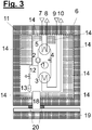
- Fig. 3 shows a refrigeration circuit with a lining and other sorption devices.
- These further sorption devices are an external container 19 filled with adsorbent under the bottom of the housing 6, which is connected to the container 6 via a connection 18, and a multiplicity of shaped bodies and shaped cushions 14. If a leakage occurs in the cooling circuit 1, the shaped bodies take 14 the refrigerant. Will be a bigger loss determined, the remaining refrigerant of the working group 1 can be drained into the container 6 via the safety refrigerant drain device 12 and the outlet with the oil collecting element 13 and the refrigerant is completely absorbed by the adsorbent in the adsorbent container 19. Sealing elements 20 are required so that no working fluid can escape.
Landscapes
- Engineering & Computer Science (AREA)
- Physics & Mathematics (AREA)
- Mechanical Engineering (AREA)
- Thermal Sciences (AREA)
- General Engineering & Computer Science (AREA)
- Separation Of Gases By Adsorption (AREA)
- Compressors, Vaccum Pumps And Other Relevant Systems (AREA)
- Solid-Sorbent Or Filter-Aiding Compositions (AREA)
- Devices That Are Associated With Refrigeration Equipment (AREA)
- Sorption Type Refrigeration Machines (AREA)
- Silicates, Zeolites, And Molecular Sieves (AREA)
Priority Applications (2)
| Application Number | Priority Date | Filing Date | Title |
|---|---|---|---|
| PL19167250T PL3581861T3 (pl) | 2018-04-23 | 2019-04-04 | Sorpcja płynów |
| HRP20210836TT HRP20210836T1 (hr) | 2018-04-23 | 2021-05-24 | Apsorpcija tekućine |
Applications Claiming Priority (1)
| Application Number | Priority Date | Filing Date | Title |
|---|---|---|---|
| DE102018109646.1A DE102018109646A1 (de) | 2018-04-23 | 2018-04-23 | Fluidsorption |
Publications (3)
| Publication Number | Publication Date |
|---|---|
| EP3581861A2 true EP3581861A2 (fr) | 2019-12-18 |
| EP3581861A3 EP3581861A3 (fr) | 2020-03-11 |
| EP3581861B1 EP3581861B1 (fr) | 2021-04-28 |
Family
ID=66092142
Family Applications (1)
| Application Number | Title | Priority Date | Filing Date |
|---|---|---|---|
| EP19167250.0A Active EP3581861B1 (fr) | 2018-04-23 | 2019-04-04 | Sorption du fluide |
Country Status (7)
| Country | Link |
|---|---|
| EP (1) | EP3581861B1 (fr) |
| DE (1) | DE102018109646A1 (fr) |
| DK (1) | DK3581861T3 (fr) |
| ES (1) | ES2874925T3 (fr) |
| HR (1) | HRP20210836T1 (fr) |
| PL (1) | PL3581861T3 (fr) |
| PT (1) | PT3581861T (fr) |
Cited By (4)
| Publication number | Priority date | Publication date | Assignee | Title |
|---|---|---|---|---|
| EP3683518A1 (fr) * | 2019-01-21 | 2020-07-22 | Viessmann Werke GmbH & Co. KG | Appareil thermotechnique |
| EP4209728A1 (fr) | 2022-01-07 | 2023-07-12 | Vaillant GmbH | Pompe à chaleur avec adsorbeur et catalyseur |
| EP4382193A1 (fr) * | 2022-12-09 | 2024-06-12 | Vaillant GmbH | Dispositif d'adsorption |
| EP4417892A1 (fr) * | 2023-02-15 | 2024-08-21 | Vaillant GmbH | Drain de condensat pour appareil de chauffage, boîtier d'appareil de chauffage et appareil de chauffage |
Families Citing this family (3)
| Publication number | Priority date | Publication date | Assignee | Title |
|---|---|---|---|---|
| DE102019118984A1 (de) * | 2019-02-06 | 2020-10-08 | Vaillant Gmbh | Diffusionssperre mittels Schutzschichten |
| DE102020120615A1 (de) * | 2020-08-05 | 2022-02-10 | Vaillant Gmbh | Aktive Abluftbehandlung für eine Wärmepumpe |
| DE102021214715A1 (de) | 2021-12-20 | 2023-06-22 | Robert Bosch Gesellschaft mit beschränkter Haftung | Wärmepumpenvorrichtung und Auffangeinheit für die Wärmepumpenvorrichtung |
Family Cites Families (14)
| Publication number | Priority date | Publication date | Assignee | Title |
|---|---|---|---|---|
| DE553295C (de) | 1931-02-03 | 1932-06-23 | Bbc Brown Boveri & Cie | Gekapselte Kompressionskaeltemaschine |
| DE3841487A1 (de) * | 1988-12-09 | 1990-06-13 | Integral Technologie Gmbh | Kaeltemaschine |
| US5165247A (en) * | 1991-02-11 | 1992-11-24 | Rocky Research | Refrigerant recycling system |
| DE9106051U1 (de) * | 1991-05-16 | 1991-12-05 | RAUM-KLIMA Technologie-GMBH., 7570 Baden-Baden | Kälte- oder Wärmeaggregat |
| DE4315924A1 (de) * | 1993-05-12 | 1994-11-17 | Forschungszentrum Fuer Kaeltet | Kälteträger für Kältemaschinen oder Wärmepumpen |
| DE19525064C1 (de) | 1995-07-10 | 1996-08-01 | Joachim Dr Ing Paul | Kältemaschine |
| DE19526980A1 (de) | 1995-07-25 | 1997-01-30 | York Int Gmbh | Verfahren und eine Vorrichtung zur Reinigung von Luft |
| US5586443A (en) * | 1995-09-20 | 1996-12-24 | Conair Corporation | Refrigerant conservation system and method |
| EP1014015A4 (fr) * | 1998-06-11 | 2001-03-14 | Sanyo Electric Co | Dispositif collecteur de fluide frigorigene, procede de collecte de liquide frigorigene, refrigerateur muni de ce dispositif, procede de regulation de liquide frigorigene dans un circuit de liquide frigorigene ou bien dispositif et procede de regeneration pour dispositif collecteur de liquide frigor |
| US8722854B2 (en) * | 2010-12-23 | 2014-05-13 | Medskin Solutions Dr. Suwelack Ag | Degradation-stabilised, biocompatible collagen matrices |
| DE102011116863A1 (de) | 2011-10-25 | 2013-04-25 | Fraunhofer-Gesellschaft zur Förderung der angewandten Forschung e.V. | Verfahren zur Sicherung einer Vorrichtung für einen thermodynamischen Kreisprozess und abgesicherte Vorrichtung für einen thermodynamischen Kreisprozess |
| WO2015032905A1 (fr) | 2013-09-05 | 2015-03-12 | Holger König | Procédé permettant d'empêcher une fuite d'un contenant et contenant pourvu d'un dispositif anti-fuite |
| DE102014112545B4 (de) * | 2014-09-01 | 2022-06-02 | Denso Automotive Deutschland Gmbh | Kompaktaggregat für ein Kraftfahrzeug und Verfahren zur Notfallbehandlung einer Kraftfahrzeugklimaanlage |
| DK3106780T3 (en) | 2015-06-17 | 2018-02-26 | Vaillant Gmbh | HEAT PUMP SYSTEM |
-
2018
- 2018-04-23 DE DE102018109646.1A patent/DE102018109646A1/de not_active Withdrawn
-
2019
- 2019-04-04 PL PL19167250T patent/PL3581861T3/pl unknown
- 2019-04-04 ES ES19167250T patent/ES2874925T3/es active Active
- 2019-04-04 DK DK19167250.0T patent/DK3581861T3/da active
- 2019-04-04 PT PT191672500T patent/PT3581861T/pt unknown
- 2019-04-04 EP EP19167250.0A patent/EP3581861B1/fr active Active
-
2021
- 2021-05-24 HR HRP20210836TT patent/HRP20210836T1/hr unknown
Cited By (4)
| Publication number | Priority date | Publication date | Assignee | Title |
|---|---|---|---|---|
| EP3683518A1 (fr) * | 2019-01-21 | 2020-07-22 | Viessmann Werke GmbH & Co. KG | Appareil thermotechnique |
| EP4209728A1 (fr) | 2022-01-07 | 2023-07-12 | Vaillant GmbH | Pompe à chaleur avec adsorbeur et catalyseur |
| EP4382193A1 (fr) * | 2022-12-09 | 2024-06-12 | Vaillant GmbH | Dispositif d'adsorption |
| EP4417892A1 (fr) * | 2023-02-15 | 2024-08-21 | Vaillant GmbH | Drain de condensat pour appareil de chauffage, boîtier d'appareil de chauffage et appareil de chauffage |
Also Published As
| Publication number | Publication date |
|---|---|
| PT3581861T (pt) | 2021-06-01 |
| PL3581861T3 (pl) | 2021-09-20 |
| ES2874925T3 (es) | 2021-11-05 |
| EP3581861A3 (fr) | 2020-03-11 |
| DK3581861T3 (da) | 2021-05-25 |
| EP3581861B1 (fr) | 2021-04-28 |
| HRP20210836T1 (hr) | 2021-10-15 |
| DE102018109646A1 (de) | 2019-10-24 |
Similar Documents
| Publication | Publication Date | Title |
|---|---|---|
| EP3486582B1 (fr) | Dispositif de détection des fuites au moyen de capacité adsorbante | |
| EP3581861B1 (fr) | Sorption du fluide | |
| EP3578895B1 (fr) | Dispositif et procédé pour le rinçage sûr et économique d'une enceinte | |
| EP4008979A1 (fr) | Dispositif pour effectuer en toute sécurité un cycle thermodynamique du sens anti-horaire | |
| EP3748257B1 (fr) | Dispositif pour la performance sûre d'un procédé circulaire thermodynamique à rotation à gauche au moyen d'un fluide de travail inflammable avec adsorption de fluide | |
| EP3486564B1 (fr) | DISPOSITIF POUR UNE MISE EN OEUVRE SÉCURITAIRE D'UN PROCESSUS DE RANKINE CLAUSIUS THERMODYNAMIQUE À COMMUTATION GAUCHE
BASÉ SUR UNE ADSORPTION DE FLUIDE DE TRAVAIL À REFOULEMENT DE GAZ INERTE | |
| EP3543629B1 (fr) | Boîtier étanche aux fuites pour un processus cyclique | |
| DE102019124531A1 (de) | Sicherheitsspülvorrichtung für eine Wärmepumpe | |
| EP3693687B1 (fr) | Refroidissement d'adsorbant | |
| EP3486583B1 (fr) | Circuit froid à sécurité anti-fuite | |
| EP3705823B1 (fr) | Dispositif pour une intervention de service en toute sécurité pour un boîtier et procédé d'ouverture du boîtier. | |
| DE102019114738A1 (de) | Fluidadsorption | |
| EP3486575B1 (fr) | Dispositif et procédé d'évacuation de sécurité du flux de travail | |
| EP3647684B1 (fr) | Zone de sécurité du condenseur | |
| EP3492846B1 (fr) | Dispositif pour effectuer en toute sécurité un cycle de rankine thermodynamique en virage à gauche et sa vidange et son remplissage en toute sécurité au moyen d'un fluide de travail inflammable et procédé pour vider en toute sécurité un fluide de travail inflammable | |
| EP3657104A1 (fr) | Pièces moulées pour pompes à chaleur | |
| EP3647685B1 (fr) | Dispositif | |
| DE102019118977A1 (de) | Adsorberkühlung | |
| DE102019121496A1 (de) | Sicherheitsspülvorrichtung für eine Wärmepumpe | |
| EP3719416A1 (fr) | Pompe à chaleur avec fluide de travail inflammable | |
| DE102018129131A1 (de) | Arbeitsfluid-Management | |
| DE102022124089A1 (de) | Adsorberentladung | |
| EP3712531A1 (fr) | Dispositif de rinçage de sécurité pour une pompe à chaleur | |
| DE102022124090A1 (de) | Thermische Adsorberentladung | |
| DE102022124104A1 (de) | Adsorberentladung durch Verdrängungsdesorption |
Legal Events
| Date | Code | Title | Description |
|---|---|---|---|
| PUAI | Public reference made under article 153(3) epc to a published international application that has entered the european phase |
Free format text: ORIGINAL CODE: 0009012 |
|
| STAA | Information on the status of an ep patent application or granted ep patent |
Free format text: STATUS: THE APPLICATION HAS BEEN PUBLISHED |
|
| AK | Designated contracting states |
Kind code of ref document: A2 Designated state(s): AL AT BE BG CH CY CZ DE DK EE ES FI FR GB GR HR HU IE IS IT LI LT LU LV MC MK MT NL NO PL PT RO RS SE SI SK SM TR |
|
| AX | Request for extension of the european patent |
Extension state: BA ME |
|
| PUAL | Search report despatched |
Free format text: ORIGINAL CODE: 0009013 |
|
| AK | Designated contracting states |
Kind code of ref document: A3 Designated state(s): AL AT BE BG CH CY CZ DE DK EE ES FI FR GB GR HR HU IE IS IT LI LT LU LV MC MK MT NL NO PL PT RO RS SE SI SK SM TR |
|
| AX | Request for extension of the european patent |
Extension state: BA ME |
|
| RIC1 | Information provided on ipc code assigned before grant |
Ipc: F25B 25/00 20060101ALI20200131BHEP Ipc: F25B 49/00 20060101AFI20200131BHEP Ipc: F25B 45/00 20060101ALI20200131BHEP |
|
| STAA | Information on the status of an ep patent application or granted ep patent |
Free format text: STATUS: REQUEST FOR EXAMINATION WAS MADE |
|
| 17P | Request for examination filed |
Effective date: 20200911 |
|
| RBV | Designated contracting states (corrected) |
Designated state(s): AL AT BE BG CH CY CZ DE DK EE ES FI FR GB GR HR HU IE IS IT LI LT LU LV MC MK MT NL NO PL PT RO RS SE SI SK SM TR |
|
| GRAP | Despatch of communication of intention to grant a patent |
Free format text: ORIGINAL CODE: EPIDOSNIGR1 |
|
| STAA | Information on the status of an ep patent application or granted ep patent |
Free format text: STATUS: GRANT OF PATENT IS INTENDED |
|
| INTG | Intention to grant announced |
Effective date: 20201117 |
|
| GRAS | Grant fee paid |
Free format text: ORIGINAL CODE: EPIDOSNIGR3 |
|
| GRAA | (expected) grant |
Free format text: ORIGINAL CODE: 0009210 |
|
| STAA | Information on the status of an ep patent application or granted ep patent |
Free format text: STATUS: THE PATENT HAS BEEN GRANTED |
|
| AK | Designated contracting states |
Kind code of ref document: B1 Designated state(s): AL AT BE BG CH CY CZ DE DK EE ES FI FR GB GR HR HU IE IS IT LI LT LU LV MC MK MT NL NO PL PT RO RS SE SI SK SM TR |
|
| REG | Reference to a national code |
Ref country code: GB Ref legal event code: FG4D Free format text: NOT ENGLISH |
|
| REG | Reference to a national code |
Ref country code: CH Ref legal event code: EP |
|
| REG | Reference to a national code |
Ref country code: DE Ref legal event code: R096 Ref document number: 502019001297 Country of ref document: DE |
|
| REG | Reference to a national code |
Ref country code: AT Ref legal event code: REF Ref document number: 1387504 Country of ref document: AT Kind code of ref document: T Effective date: 20210515 |
|
| REG | Reference to a national code |
Ref country code: HR Ref legal event code: TUEP Ref document number: P20210836T Country of ref document: HR |
|
| REG | Reference to a national code |
Ref country code: DK Ref legal event code: T3 Effective date: 20210520 |
|
| REG | Reference to a national code |
Ref country code: IE Ref legal event code: FG4D Free format text: LANGUAGE OF EP DOCUMENT: GERMAN |
|
| REG | Reference to a national code |
Ref country code: PT Ref legal event code: SC4A Ref document number: 3581861 Country of ref document: PT Date of ref document: 20210601 Kind code of ref document: T Free format text: AVAILABILITY OF NATIONAL TRANSLATION Effective date: 20210524 |
|
| REG | Reference to a national code |
Ref country code: NL Ref legal event code: FP |
|
| REG | Reference to a national code |
Ref country code: SE Ref legal event code: TRGR |
|
| REG | Reference to a national code |
Ref country code: LT Ref legal event code: MG9D |
|
| REG | Reference to a national code |
Ref country code: SK Ref legal event code: T3 Ref document number: E 37715 Country of ref document: SK |
|
| REG | Reference to a national code |
Ref country code: HR Ref legal event code: T1PR Ref document number: P20210836 Country of ref document: HR |
|
| PG25 | Lapsed in a contracting state [announced via postgrant information from national office to epo] |
Ref country code: LT Free format text: LAPSE BECAUSE OF FAILURE TO SUBMIT A TRANSLATION OF THE DESCRIPTION OR TO PAY THE FEE WITHIN THE PRESCRIBED TIME-LIMIT Effective date: 20210428 Ref country code: FI Free format text: LAPSE BECAUSE OF FAILURE TO SUBMIT A TRANSLATION OF THE DESCRIPTION OR TO PAY THE FEE WITHIN THE PRESCRIBED TIME-LIMIT Effective date: 20210428 Ref country code: BG Free format text: LAPSE BECAUSE OF FAILURE TO SUBMIT A TRANSLATION OF THE DESCRIPTION OR TO PAY THE FEE WITHIN THE PRESCRIBED TIME-LIMIT Effective date: 20210728 |
|
| REG | Reference to a national code |
Ref country code: ES Ref legal event code: FG2A Ref document number: 2874925 Country of ref document: ES Kind code of ref document: T3 Effective date: 20211105 |
|
| PG25 | Lapsed in a contracting state [announced via postgrant information from national office to epo] |
Ref country code: IS Free format text: LAPSE BECAUSE OF FAILURE TO SUBMIT A TRANSLATION OF THE DESCRIPTION OR TO PAY THE FEE WITHIN THE PRESCRIBED TIME-LIMIT Effective date: 20210828 Ref country code: GR Free format text: LAPSE BECAUSE OF FAILURE TO SUBMIT A TRANSLATION OF THE DESCRIPTION OR TO PAY THE FEE WITHIN THE PRESCRIBED TIME-LIMIT Effective date: 20210729 Ref country code: NO Free format text: LAPSE BECAUSE OF FAILURE TO SUBMIT A TRANSLATION OF THE DESCRIPTION OR TO PAY THE FEE WITHIN THE PRESCRIBED TIME-LIMIT Effective date: 20210728 Ref country code: LV Free format text: LAPSE BECAUSE OF FAILURE TO SUBMIT A TRANSLATION OF THE DESCRIPTION OR TO PAY THE FEE WITHIN THE PRESCRIBED TIME-LIMIT Effective date: 20210428 Ref country code: RS Free format text: LAPSE BECAUSE OF FAILURE TO SUBMIT A TRANSLATION OF THE DESCRIPTION OR TO PAY THE FEE WITHIN THE PRESCRIBED TIME-LIMIT Effective date: 20210428 |
|
| PG25 | Lapsed in a contracting state [announced via postgrant information from national office to epo] |
Ref country code: RO Free format text: LAPSE BECAUSE OF FAILURE TO SUBMIT A TRANSLATION OF THE DESCRIPTION OR TO PAY THE FEE WITHIN THE PRESCRIBED TIME-LIMIT Effective date: 20210428 Ref country code: SM Free format text: LAPSE BECAUSE OF FAILURE TO SUBMIT A TRANSLATION OF THE DESCRIPTION OR TO PAY THE FEE WITHIN THE PRESCRIBED TIME-LIMIT Effective date: 20210428 Ref country code: EE Free format text: LAPSE BECAUSE OF FAILURE TO SUBMIT A TRANSLATION OF THE DESCRIPTION OR TO PAY THE FEE WITHIN THE PRESCRIBED TIME-LIMIT Effective date: 20210428 |
|
| REG | Reference to a national code |
Ref country code: DE Ref legal event code: R097 Ref document number: 502019001297 Country of ref document: DE |
|
| PLBE | No opposition filed within time limit |
Free format text: ORIGINAL CODE: 0009261 |
|
| STAA | Information on the status of an ep patent application or granted ep patent |
Free format text: STATUS: NO OPPOSITION FILED WITHIN TIME LIMIT |
|
| 26N | No opposition filed |
Effective date: 20220131 |
|
| REG | Reference to a national code |
Ref country code: HR Ref legal event code: ODRP Ref document number: P20210836 Country of ref document: HR Payment date: 20220329 Year of fee payment: 4 |
|
| PG25 | Lapsed in a contracting state [announced via postgrant information from national office to epo] |
Ref country code: IS Free format text: LAPSE BECAUSE OF FAILURE TO SUBMIT A TRANSLATION OF THE DESCRIPTION OR TO PAY THE FEE WITHIN THE PRESCRIBED TIME-LIMIT Effective date: 20210828 Ref country code: AL Free format text: LAPSE BECAUSE OF FAILURE TO SUBMIT A TRANSLATION OF THE DESCRIPTION OR TO PAY THE FEE WITHIN THE PRESCRIBED TIME-LIMIT Effective date: 20210428 |
|
| PG25 | Lapsed in a contracting state [announced via postgrant information from national office to epo] |
Ref country code: MC Free format text: LAPSE BECAUSE OF FAILURE TO SUBMIT A TRANSLATION OF THE DESCRIPTION OR TO PAY THE FEE WITHIN THE PRESCRIBED TIME-LIMIT Effective date: 20210428 Ref country code: LU Free format text: LAPSE BECAUSE OF NON-PAYMENT OF DUE FEES Effective date: 20220404 |
|
| REG | Reference to a national code |
Ref country code: HR Ref legal event code: ODRP Ref document number: P20210836 Country of ref document: HR Payment date: 20230327 Year of fee payment: 5 |
|
| PGFP | Annual fee paid to national office [announced via postgrant information from national office to epo] |
Ref country code: PT Payment date: 20230321 Year of fee payment: 5 Ref country code: HR Payment date: 20230327 Year of fee payment: 5 Ref country code: BE Payment date: 20230328 Year of fee payment: 5 |
|
| PGFP | Annual fee paid to national office [announced via postgrant information from national office to epo] |
Ref country code: IE Payment date: 20230420 Year of fee payment: 5 |
|
| PGFP | Annual fee paid to national office [announced via postgrant information from national office to epo] |
Ref country code: NL Payment date: 20240325 Year of fee payment: 6 |
|
| PG25 | Lapsed in a contracting state [announced via postgrant information from national office to epo] |
Ref country code: MK Free format text: LAPSE BECAUSE OF FAILURE TO SUBMIT A TRANSLATION OF THE DESCRIPTION OR TO PAY THE FEE WITHIN THE PRESCRIBED TIME-LIMIT Effective date: 20210428 Ref country code: CY Free format text: LAPSE BECAUSE OF FAILURE TO SUBMIT A TRANSLATION OF THE DESCRIPTION OR TO PAY THE FEE WITHIN THE PRESCRIBED TIME-LIMIT Effective date: 20210428 |
|
| PGFP | Annual fee paid to national office [announced via postgrant information from national office to epo] |
Ref country code: GB Payment date: 20240325 Year of fee payment: 6 Ref country code: SK Payment date: 20240402 Year of fee payment: 6 |
|
| PG25 | Lapsed in a contracting state [announced via postgrant information from national office to epo] |
Ref country code: HU Free format text: LAPSE BECAUSE OF FAILURE TO SUBMIT A TRANSLATION OF THE DESCRIPTION OR TO PAY THE FEE WITHIN THE PRESCRIBED TIME-LIMIT; INVALID AB INITIO Effective date: 20190404 |
|
| PGFP | Annual fee paid to national office [announced via postgrant information from national office to epo] |
Ref country code: TR Payment date: 20240329 Year of fee payment: 6 |
|
| PGFP | Annual fee paid to national office [announced via postgrant information from national office to epo] |
Ref country code: DE Payment date: 20240325 Year of fee payment: 6 |
|
| PGFP | Annual fee paid to national office [announced via postgrant information from national office to epo] |
Ref country code: DK Payment date: 20240419 Year of fee payment: 6 |
|
| PGFP | Annual fee paid to national office [announced via postgrant information from national office to epo] |
Ref country code: CH Payment date: 20240501 Year of fee payment: 6 |
|
| PGFP | Annual fee paid to national office [announced via postgrant information from national office to epo] |
Ref country code: ES Payment date: 20240503 Year of fee payment: 6 |
|
| PGFP | Annual fee paid to national office [announced via postgrant information from national office to epo] |
Ref country code: CZ Payment date: 20240402 Year of fee payment: 6 Ref country code: AT Payment date: 20240403 Year of fee payment: 6 |
|
| PGFP | Annual fee paid to national office [announced via postgrant information from national office to epo] |
Ref country code: IT Payment date: 20240426 Year of fee payment: 6 Ref country code: FR Payment date: 20240423 Year of fee payment: 6 |
|
| PGFP | Annual fee paid to national office [announced via postgrant information from national office to epo] |
Ref country code: PL Payment date: 20240402 Year of fee payment: 6 |
|
| PGFP | Annual fee paid to national office [announced via postgrant information from national office to epo] |
Ref country code: SE Payment date: 20240424 Year of fee payment: 6 |