EP3486575B1 - Dispositif et procédé d'évacuation de sécurité du flux de travail - Google Patents
Dispositif et procédé d'évacuation de sécurité du flux de travail Download PDFInfo
- Publication number
- EP3486575B1 EP3486575B1 EP18198122.6A EP18198122A EP3486575B1 EP 3486575 B1 EP3486575 B1 EP 3486575B1 EP 18198122 A EP18198122 A EP 18198122A EP 3486575 B1 EP3486575 B1 EP 3486575B1
- Authority
- EP
- European Patent Office
- Prior art keywords
- housing
- drain
- shut
- valve
- working fluid
- Prior art date
- Legal status (The legal status is an assumption and is not a legal conclusion. Google has not performed a legal analysis and makes no representation as to the accuracy of the status listed.)
- Active
Links
- 239000012530 fluid Substances 0.000 title claims description 37
- 238000000034 method Methods 0.000 title claims description 23
- 239000011261 inert gas Substances 0.000 claims description 31
- 238000001816 cooling Methods 0.000 claims description 24
- 239000000203 mixture Substances 0.000 claims description 14
- 239000003990 capacitor Substances 0.000 claims description 2
- 238000007689 inspection Methods 0.000 claims 5
- ATUOYWHBWRKTHZ-UHFFFAOYSA-N Propane Chemical compound CCC ATUOYWHBWRKTHZ-UHFFFAOYSA-N 0.000 description 76
- 239000001294 propane Substances 0.000 description 38
- 238000005057 refrigeration Methods 0.000 description 37
- 239000003570 air Substances 0.000 description 21
- 239000007789 gas Substances 0.000 description 13
- 239000003507 refrigerant Substances 0.000 description 12
- 239000003380 propellant Substances 0.000 description 8
- 230000008569 process Effects 0.000 description 7
- XLYOFNOQVPJJNP-UHFFFAOYSA-N water Substances O XLYOFNOQVPJJNP-UHFFFAOYSA-N 0.000 description 6
- 238000013461 design Methods 0.000 description 5
- 239000013529 heat transfer fluid Substances 0.000 description 5
- 238000010438 heat treatment Methods 0.000 description 5
- 230000007257 malfunction Effects 0.000 description 5
- CURLTUGMZLYLDI-UHFFFAOYSA-N Carbon dioxide Chemical compound O=C=O CURLTUGMZLYLDI-UHFFFAOYSA-N 0.000 description 4
- 238000004880 explosion Methods 0.000 description 4
- 239000002360 explosive Substances 0.000 description 4
- 230000009467 reduction Effects 0.000 description 4
- 238000006424 Flood reaction Methods 0.000 description 3
- 238000004378 air conditioning Methods 0.000 description 3
- 238000011109 contamination Methods 0.000 description 3
- 238000001514 detection method Methods 0.000 description 3
- 238000012423 maintenance Methods 0.000 description 3
- 238000012360 testing method Methods 0.000 description 3
- 238000009423 ventilation Methods 0.000 description 3
- IJGRMHOSHXDMSA-UHFFFAOYSA-N Atomic nitrogen Chemical compound N#N IJGRMHOSHXDMSA-UHFFFAOYSA-N 0.000 description 2
- 239000006096 absorbing agent Substances 0.000 description 2
- 239000012267 brine Substances 0.000 description 2
- 239000002775 capsule Substances 0.000 description 2
- 229910002092 carbon dioxide Inorganic materials 0.000 description 2
- 239000001569 carbon dioxide Substances 0.000 description 2
- 230000006835 compression Effects 0.000 description 2
- 238000007906 compression Methods 0.000 description 2
- 238000011161 development Methods 0.000 description 2
- 238000006073 displacement reaction Methods 0.000 description 2
- NNPPMTNAJDCUHE-UHFFFAOYSA-N isobutane Chemical compound CC(C)C NNPPMTNAJDCUHE-UHFFFAOYSA-N 0.000 description 2
- VNWKTOKETHGBQD-UHFFFAOYSA-N methane Chemical compound C VNWKTOKETHGBQD-UHFFFAOYSA-N 0.000 description 2
- 239000003921 oil Substances 0.000 description 2
- 239000008188 pellet Substances 0.000 description 2
- 231100000614 poison Toxicity 0.000 description 2
- 230000007096 poisonous effect Effects 0.000 description 2
- HPALAKNZSZLMCH-UHFFFAOYSA-M sodium;chloride;hydrate Chemical compound O.[Na+].[Cl-] HPALAKNZSZLMCH-UHFFFAOYSA-M 0.000 description 2
- 238000012546 transfer Methods 0.000 description 2
- 238000013022 venting Methods 0.000 description 2
- 238000010792 warming Methods 0.000 description 2
- 241001295925 Gegenes Species 0.000 description 1
- 206010019233 Headaches Diseases 0.000 description 1
- 206010028813 Nausea Diseases 0.000 description 1
- CBENFWSGALASAD-UHFFFAOYSA-N Ozone Chemical compound [O-][O+]=O CBENFWSGALASAD-UHFFFAOYSA-N 0.000 description 1
- 150000001338 aliphatic hydrocarbons Chemical class 0.000 description 1
- 239000012080 ambient air Substances 0.000 description 1
- QVGXLLKOCUKJST-UHFFFAOYSA-N atomic oxygen Chemical compound [O] QVGXLLKOCUKJST-UHFFFAOYSA-N 0.000 description 1
- 238000004140 cleaning Methods 0.000 description 1
- 239000003245 coal Substances 0.000 description 1
- 239000000498 cooling water Substances 0.000 description 1
- 238000003745 diagnosis Methods 0.000 description 1
- 238000007599 discharging Methods 0.000 description 1
- 239000006185 dispersion Substances 0.000 description 1
- 230000000694 effects Effects 0.000 description 1
- 238000005516 engineering process Methods 0.000 description 1
- 238000001704 evaporation Methods 0.000 description 1
- 230000008020 evaporation Effects 0.000 description 1
- 230000002349 favourable effect Effects 0.000 description 1
- 239000002803 fossil fuel Substances 0.000 description 1
- 231100000869 headache Toxicity 0.000 description 1
- 238000005338 heat storage Methods 0.000 description 1
- 229930195733 hydrocarbon Natural products 0.000 description 1
- 150000002430 hydrocarbons Chemical class 0.000 description 1
- 230000003993 interaction Effects 0.000 description 1
- 230000001788 irregular Effects 0.000 description 1
- 239000001282 iso-butane Substances 0.000 description 1
- 239000007788 liquid Substances 0.000 description 1
- 230000003533 narcotic effect Effects 0.000 description 1
- 239000003345 natural gas Substances 0.000 description 1
- 230000008693 nausea Effects 0.000 description 1
- 229910052757 nitrogen Inorganic materials 0.000 description 1
- 239000001301 oxygen Substances 0.000 description 1
- 229910052760 oxygen Inorganic materials 0.000 description 1
- 239000002994 raw material Substances 0.000 description 1
- 230000008439 repair process Effects 0.000 description 1
- 239000002594 sorbent Substances 0.000 description 1
- 230000009182 swimming Effects 0.000 description 1
- 230000007306 turnover Effects 0.000 description 1
- 239000002918 waste heat Substances 0.000 description 1
- 238000004804 winding Methods 0.000 description 1
- 239000002023 wood Substances 0.000 description 1
Images
Classifications
-
- F—MECHANICAL ENGINEERING; LIGHTING; HEATING; WEAPONS; BLASTING
- F24—HEATING; RANGES; VENTILATING
- F24F—AIR-CONDITIONING; AIR-HUMIDIFICATION; VENTILATION; USE OF AIR CURRENTS FOR SCREENING
- F24F11/00—Control or safety arrangements
- F24F11/30—Control or safety arrangements for purposes related to the operation of the system, e.g. for safety or monitoring
- F24F11/32—Responding to malfunctions or emergencies
- F24F11/36—Responding to malfunctions or emergencies to leakage of heat-exchange fluid
-
- F—MECHANICAL ENGINEERING; LIGHTING; HEATING; WEAPONS; BLASTING
- F25—REFRIGERATION OR COOLING; COMBINED HEATING AND REFRIGERATION SYSTEMS; HEAT PUMP SYSTEMS; MANUFACTURE OR STORAGE OF ICE; LIQUEFACTION SOLIDIFICATION OF GASES
- F25B—REFRIGERATION MACHINES, PLANTS OR SYSTEMS; COMBINED HEATING AND REFRIGERATION SYSTEMS; HEAT PUMP SYSTEMS
- F25B49/00—Arrangement or mounting of control or safety devices
- F25B49/02—Arrangement or mounting of control or safety devices for compression type machines, plants or systems
-
- F—MECHANICAL ENGINEERING; LIGHTING; HEATING; WEAPONS; BLASTING
- F25—REFRIGERATION OR COOLING; COMBINED HEATING AND REFRIGERATION SYSTEMS; HEAT PUMP SYSTEMS; MANUFACTURE OR STORAGE OF ICE; LIQUEFACTION SOLIDIFICATION OF GASES
- F25B—REFRIGERATION MACHINES, PLANTS OR SYSTEMS; COMBINED HEATING AND REFRIGERATION SYSTEMS; HEAT PUMP SYSTEMS
- F25B2339/00—Details of evaporators; Details of condensers
- F25B2339/04—Details of condensers
- F25B2339/047—Water-cooled condensers
-
- F—MECHANICAL ENGINEERING; LIGHTING; HEATING; WEAPONS; BLASTING
- F25—REFRIGERATION OR COOLING; COMBINED HEATING AND REFRIGERATION SYSTEMS; HEAT PUMP SYSTEMS; MANUFACTURE OR STORAGE OF ICE; LIQUEFACTION SOLIDIFICATION OF GASES
- F25B—REFRIGERATION MACHINES, PLANTS OR SYSTEMS; COMBINED HEATING AND REFRIGERATION SYSTEMS; HEAT PUMP SYSTEMS
- F25B2400/00—General features or devices for refrigeration machines, plants or systems, combined heating and refrigeration systems or heat-pump systems, i.e. not limited to a particular subgroup of F25B
- F25B2400/12—Inflammable refrigerants
-
- F—MECHANICAL ENGINEERING; LIGHTING; HEATING; WEAPONS; BLASTING
- F25—REFRIGERATION OR COOLING; COMBINED HEATING AND REFRIGERATION SYSTEMS; HEAT PUMP SYSTEMS; MANUFACTURE OR STORAGE OF ICE; LIQUEFACTION SOLIDIFICATION OF GASES
- F25B—REFRIGERATION MACHINES, PLANTS OR SYSTEMS; COMBINED HEATING AND REFRIGERATION SYSTEMS; HEAT PUMP SYSTEMS
- F25B2500/00—Problems to be solved
- F25B2500/22—Preventing, detecting or repairing leaks of refrigeration fluids
Definitions
- the invention relates to irregular states in refrigeration circuits in which a working fluid acting as a refrigerant is conducted in a thermodynamic cycle, such as the Rankine cycle, for example.
- thermodynamic cycle such as the Rankine cycle
- These are mainly heat pumps, air conditioning systems and cooling devices, as are common in residential buildings.
- Residential buildings are understood to mean private houses, apartment complexes, hospitals, hotel facilities, restaurants and combined residential and commercial buildings in which people live and work permanently, in contrast to mobile devices such as car air conditioning systems or transport boxes, or industrial systems or medical devices. What these cycle processes have in common is that they generate useful heat or useful cooling using energy and form heat displacement systems.
- thermodynamic cycle processes used have been known for a long time, as have the safety problems that can arise when using suitable working fluids. Apart from water, the most popular working fluids of the time are flammable and poisonous. In the past century, they led to the development of safety refrigerants, which consisted of fluorinated hydrocarbons. It turned out, however, that these safety refrigerants damage the ozone layer, lead to global warming, and that their safety-related harmlessness led to constructive inattention. Up to 70% of the turnover was accounted for by the need to refill leaky systems and their leakage losses, which was accepted as long as this was perceived as economically justifiable in individual cases and promoted the need for replacement.
- the problems that arise in the safety design of such systems are in the WO 2015/032905 A1 clearly described.
- the lower flammability limit of propane as a working fluid is around 1.7 percent by volume in air, which corresponds to 38 g / m 3 in air.
- the cooling process is carried out in a hermetically sealed, otherwise air-filled room with the working fluid propane , the problem arises of recognizing a critical, explosive situation after a fault, in which the working fluid escapes into this hermetically sealed space.
- Electrical sensors for detecting critical concentrations are difficult to design with explosion protection, which is why the propane detection by the sensors themselves increases the risk of explosion considerably, with the exception of infrared sensors.
- Propane is also poisonous; inhalation above a concentration of approx. 2 g / m 3 results in narcotic effects, headaches and nausea. This affects people who are supposed to solve a recognized problem on site before there is a risk of explosion.
- Propane is also heavier than air, so in still air it sinks to the floor and collects there. So if some of the propane collects in a low-flow zone of the closed space in which the disturbed unit is located, the local explosion limits can be reached much faster than the quotient of the total volume of the space to the amount of propane that has escaped would suggest.
- the WO 2015/032905 A1 seeks to solve this problem by integrating a generator for electrical current into the opening or locking of this room and, when activated, in a first step generates and provides the electrical energy with which the sensor is activated, and in the event of an alarm the The lock then does not release, but causes ventilation of the locked room, and only allows unlocking and opening in a second step.
- the DE-PS 553 295 describes an encapsulated compression refrigeration machine in which the refrigerant compressor 1, its drive motor 2, evaporator 3, condenser 4 and control valve 5 are enclosed in a double-walled capsule 6 and 7, respectively.
- a negative pressure is created in the space between the double-walled capsule and leaks that could occur at the openings for cooling water and brine are sucked out.
- the extracted working fluid can then be recovered if necessary. It should be noted here that there is no ambient air inside the encapsulated space and, due to the negative pressure in the double jacket, it cannot penetrate into the encapsulated interior.
- the DE 195 26 980 A1 describes an apparatus and a method for cleaning air in enclosed spaces which have a gaseous contamination. After the contamination has been detected by a gas sensor, it controls a compressor, which directs the air through an absorber located in this room, whereby the contamination is absorbed. The cleaned air leaves the absorber in the closed room.
- the FR 2 827 948 A1 describes an internally installed heat pump which is operated with propane or isobutane and which has an encapsulated area in which the cooling circuit is arranged.
- This encapsulated area becomes a line to the outside out of which the refrigerant can escape unfiltered in the event of a leak.
- a wall opening, a connection to an external unit or a fan-assisted ventilation of the encapsulated area is provided.
- the object of the invention is therefore to provide a device and a method for the safe and automatic discharge of a flammable working fluid.
- the invention achieves this object by a device according to claim 1 and by a method according to claim 4.
- Heat transfer fluids are to be understood here as all gaseous or liquid media with which heat is transferred, for example air, water, brine, heat transfer oils or the like.
- the drain from the housing should be directed to a location outside the building that does not have any sinks in the floor.
- the shut-off valves should be secured against unintentional backflow by non-return devices.
- an ejector (18) is connected between the shut-off valve (15), which separates the outlet (11) from the refrigeration circuit (1), and the outlet (11), which is connected to a jet line (21). is connected via a shut-off valve (20) to the pressurized inert gas container (19).
- a shut-off valve (16) is arranged in the refrigeration circuit (1) between the compressor (2) and the condenser (3), with the line (17) leading to the drain before the shut-off valve (16) branches off and the connecting line to the inert gas container (19) branches off after the shut-off valve (16).
- the shut-off valve behind the compressor is opened and the pressurized working fluid is released into the open.
- Most flammable working fluids are aliphatic hydrocarbons, in the simplest case this is propane. Propane is therefore chosen as an example below, but the invention is not restricted to propane as the working fluid.
- the process of releasing it into the open is a common procedure, since propane has only a low climate effect, about 3.3 times that of carbon dioxide, which is practically insignificant in the usual amounts used in refrigeration circuits.
- propane has only a low climate effect, about 3.3 times that of carbon dioxide, which is practically insignificant in the usual amounts used in refrigeration circuits.
- a case distinction must be made when discharging into the open, in order to always ensure that an explosive mixture can never occur.
- the invention solves this problem by a method using the device according to the invention by, after the detection of a Leakage is first checked whether an ignitable mixture of working fluid and air has formed inside the housing (6) and whether there is a pressure drop in the refrigeration circuit (1).
- the first thing to do is to check whether there has been a pressure drop in the cooling circuit. In the event that no pressure drop has occurred, a two-phase area in the refrigeration cycle can still be assumed and a massive leak can initially be ruled out.
- the pressure under which the cooling circuit is can then be used as a driving force for the promotion of the propane into the open air and it is also sufficient for dispersion by means of a dispersing nozzle.
- the drain must not be located above a depression in the ground, since propane, like almost all other flammable working fluids, is heavier than air and could sink into such a depression and form an inflammable mixture.
- Such sinks are, for example, cellar windows secured with grating or manhole covers for drainage or cellar stairs.
- one embodiment of the invention provides that the shut-off valve of the refrigeration circuit is closed and the shut-off valve for the inert gas to the housing and, at the same time, the shut-off valve from the housing to the drain is opened.
- the inert gas presses in this case, the propane-air mixture from the housing through the outlet and, due to the inertization, simultaneously causes the tendency to ignite to decrease.
- Carbon dioxide is preferably used as the inerting gas. If other inert gases or gas mixtures are used, their Joule-Thomson coefficient must be observed so that no ice forms during the pressure drop, as would be the case, for example, if pure nitrogen were used.
- the gaseous content of the housing is sucked off and mixed with an inert gas before it is guided out of the housing (6) to a location outside the building (13).
- the suction takes place by means of an ejector (18) and the inert gas is mixed in as a propellant jet.
- the pressurized working fluid directly or is fed into the drain (11) with the assistance of the compressor, the refrigeration circuit being interrupted by a shut-off valve (16) between the drain line (17) and the evaporator (3).
- the last part of the propane in the refrigeration circuit can only be vented slowly by simply opening the shut-off valve, which is undesirable in an emergency.
- the shut-off valve from the inert gas tank to the refrigeration circuit is opened and the refrigeration circuit is flushed with inert gas under pressure.
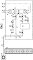
- FIG. 1 a schematic of a refrigeration cycle with the refrigerant propane and the safety devices provided using the example of a domestic heat pump.
- Fig. 1 shows a conventional refrigeration circuit 1 with a compressor 2, a condenser 3, a pressure reduction 4 and an evaporator in a closed housing 6.
- the housing 6 is usually soundproofed and therefore made airtight, it can withstand slight overpressure. Structurally, water storage and switching elements can be integrated.
- the housing 6 has line connections for the heat source, the heat source connection 7 and the heat source flow 8, and the heating circuit with the heat sink flow 9 and the heat sink connection 10.
- cooling circuit shown here in simplified form can also contain several heat exchangers at different temperature levels, a stepped pressure reduction, switching devices for heating operation in winter and cooling in summer, as well as a large number of sensors, although the following safety devices are identical.
- a discharge line 11 leading out of the housing is provided, which is secured against suction from the outside by a kickback device and ends outside the residential building wall 13 in a disperser 14.
- the disperser is designed as a swirl passage, depending on the local conditions, a large number of other designs are also possible. It is important that no strands are formed and that the air is mixed as much as possible so that there is a safe distance from the ignition limits to a propane-air mixture that is formed when propane is released.
- the type of safe discharge of propane depends on the type of accident or the quality of the information and the circumstances that exist in this regard. External circumstances such as power outages, fires, earthquakes, floods and accidents must be distinguished from internal incidents such as the occurrence of leaks or very rare major faults and those that result from the interaction with connected external heat sources and heat sinks.
- the detection means required for this are not the subject of the invention, but are assumed below as being present within the framework of the known prior art and are not shown separately.
- the drain shut-off valve 15 is opened, the pressure reduction 4 opened and the refrigeration circuit shut-off valve 16 closed .
- the propane flowing under pressure into the ejector inlet line 17 is fed into the ejector 18, but does not have to be supported by propellant gas.
- the pressure in the refrigeration circuit is essentially constant and only depends on the temperature. If the heat source and heat sink connections are also closed, the temperature remains largely constant, since the heat capacity present in the housing 6 in the condenser 3 compensates for the loss of heat of evaporation of the propane. Most of the propane can be drained in this way. The situation is different if there is no hot water in the condenser. In this case, a drop in temperature and, associated with this, a drop in pressure in the refrigeration circuit must be expected.
- the compressor 2 can be used for further conveyance and pressure increase, provided that there is no power failure or compressor failure.
- the shut-off valve 22 can be opened in order to fill inert gas from the inert gas pressure vessel 19 into the refrigeration circuit 1 and to maintain the pressure.
- inert gas can also be fed from the propellant gas line 21 into the ejector 18 in order to suck propane out of the refrigeration circuit and feed it into the disperser 14 at such a pressure that there is still sufficient swirling or mixing with the outside air .
- the drain shut-off valve 15 and the refrigeration circuit inertization shut-off valve 22 can be closed.
- the housing 6 then has to be flushed with inert gas, since the previous propane leakage could also result in too much propane in the housing.
- the housing evacuation shut-off valve 26 is opened, and air can be sucked from the housing 6 into the ejector inlet line 17 through the evacuation inlet 27 and the filter 28.
- a kickback device 29 ensures that any residual propane could flow into the housing due to malfunctions.
- the housing inertization shut-off valve 24 is to be opened at the same time, which allows as much inert gas to flow into the housing via the inert gas outlet 25 as is discharged through the evacuation inlet 27.
- the known pendulum gas process should preferably be used here.
- the refrigerant circuit shut-off valve is not closed.
- the housing evacuation shut-off valve is also opened from the start in order to counteract any overpressure that may arise in the housing, be it from escaping propane or from external heat. If the housing has already been damaged and there are no people in the vicinity, the housing inertization shut-off valve is also opened in order to deprive a fire of the oxygen outside the housing.
- the pressure in the refrigeration circuit must be kept at the pressure of the heat transfer fluid.
- the refrigeration circuit inertization shut-off valve 22 which for this case can also be designed as a control valve, is opened in order to feed inert gas into the refrigeration circuit 1 and slightly increase the pressure.
- the connections 7-10 closed.
- the propane must be removed under pressure, with the compressor switched off and the ejector operated with propellant gas. In this way, a safe propane discharge is guaranteed even with the entrainment of heat transfer fluid.
Landscapes
- Engineering & Computer Science (AREA)
- Mechanical Engineering (AREA)
- General Engineering & Computer Science (AREA)
- Chemical & Material Sciences (AREA)
- Combustion & Propulsion (AREA)
- Physics & Mathematics (AREA)
- Thermal Sciences (AREA)
- Devices That Are Associated With Refrigeration Equipment (AREA)
- Filling Or Discharging Of Gas Storage Vessels (AREA)
- Electrical Discharge Machining, Electrochemical Machining, And Combined Machining (AREA)
Claims (8)
- Dispositif pour la réalisation en toute sécurité d'un processus thermodynamique à rotation à gauche de Clausius Rankine dans un bâtiment résidentiel (13) au moyen d'un fluide de travail inflammable, lequel est plus lourd que l'air dans un état gazeux en conditions atmosphériques et est mené dans un circuit de refroidissement (1) fermé de manière hermétiquement étanche, dans lequel un fluide de travail circule, présentant- au moins un compresseur (2) pour du fluide de travail,- au moins un dispositif de détente (4) pour du fluide de travail,- au moins deux échangeurs de chaleur (3, 5) pour du fluide de travail avec respectivement au moins deux raccords (7, 8, 9, 10) pour des fluides de transfert de chaleur,- un boîtier (6) fermé, lequel comprend tous les appareils reliés au circuit de refroidissement (1) et peut comprendre d'autres appareils,
caractérisé en ce que- le circuit de refroidissement (1) est raccordé par une conduite (17) menant à l'évacuation à une évacuation (11), qui est agencée dans le sens du courant suivant le compresseur (2) et l'évacuation (11) est séparée du circuit de refroidissement (1) par une vanne d'arrêt (15),- l'intérieur de boîtier (6) est raccordé à l'évacuation (11) et l'évacuation est séparée de l'intérieur de boîtier (6) par une vanne d'arrêt (26),- l'évacuation (11) peut être menée du boîtier à un endroit à l'extérieur du bâtiment résidentiel (13),- un dispositif pour la dispersion (14) est agencé à la sortie de l'évacuation, et- un gaz inerte maintenu sous pression est stocké dans au moins un réservoir de gaz inerte (19), et ce réservoir de gaz inerte (19) est raccordé à la fois au circuit de refroidissement (1) et à l'intérieur de boîtier (6) via une vanne d'arrêt (22, 24). - Dispositif selon la revendication 1, caractérisé en ce que, entre la vanne d'arrêt (15), laquelle sépare l'évacuation (11) du circuit de refroidissement (1), et un éjecteur (18) est relié à l'évacuation (11), qui est reliée avec une conduite de jet d'expulsion (21) via une vanne d'arrêt (20) au réservoir de gaz inerte (19) maintenu sous pression.
- Dispositif selon l'une quelconque des revendications 1 ou 2, caractérisé en ce qu'une vanne d'arrêt (16) est agencée dans le circuit de refroidissement (1) entre le compresseur (2) et le condenseur (3), dans lequel la conduite (17) menant à l'évacuation bifurque devant la vanne d'arrêt (16) et la conduite de raccordement bifurque vers le réservoir de gaz inerte (19) après la vanne d'arrêt (16).
- Procédé d'évacuation de sécurité d'un circuit de refroidissement et du boîtier l'entourant selon l'une quelconque des revendications 1 à 3,
caractérisé en ce que- après la détection d'une fuite, on vérifie d'abord si un mélange inflammable de fluide de travail et d'air s'est formé dans l'intérieur du boîtier (6)- et si une chute de pression se produit dans le circuit de refroidissement (1). - Procédé selon la revendication 4, caractérisé en ce que, après un examen positif visant à déterminer si un mélange inflammable de fluide de travail et d'air s'est formé dans le boîtier, l'intérieur du boîtier (6) est d'abord rendu inerte en ouvrant la vanne d'arrêt (26), laquelle raccorde l'intérieur du boîtier (6) à l'évacuation (11) et du gaz inerte est mené de manière simultanée du réservoir de gaz inerte (19) dans l'intérieur du boîtier.
- Procédé selon la revendication 5 correspondant à un dispositif selon les revendications 2 ou 3, caractérisé en ce que le contenu gazeux du boîtier est aspiré au moyen d'un éjecteur (18) et ainsi mélangé avec un gaz inerte comme jet d'expulsion, avant qu'il soit mené du boîtier (6) à un endroit à l'extérieur du bâtiment résidentiel (13).
- Procédé selon la revendication 4 correspondant à un dispositif selon les revendications 2 ou 3, caractérisé en ce que, après un examen négatif visant à déterminer si un mélange inflammable de fluide de travail et d'air s'est formé dans le boîtier, et un examen positif visant à déterminer si une chute de pression se produit dans le circuit de refroidissement (1), le contenu gazeux du circuit de refroidissement (1) est aspiré au moyen d'un éjecteur (18) et ainsi mélangé avec un gaz inerte comme jet d'expulsion, avant qu'il soit mené du boîtier (6) à un endroit à l'extérieur du bâtiment résidentiel (13).
- Procédé selon la revendication 4 correspondant à un dispositif selon la revendication 3, caractérisé en ce que, après un examen négatif visant à déterminer si un mélange inflammable de fluide de travail et d'air s'est formé dans le boîtier, et un examen négatif visant à déterminer si une chute de pression se produit dans le circuit de refroidissement (1), le fluide de travail se trouvant sous pression est distribué directement ou avec l'assistance du compresseur dans l'évacuation (11), dans lequel le circuit de refroidissement est interrompu par une vanne d'arrêt (16) entre la conduite d'évacuation (17) et l'évaporateur (3).
Priority Applications (2)
| Application Number | Priority Date | Filing Date | Title |
|---|---|---|---|
| PL18198122T PL3486575T3 (pl) | 2017-11-16 | 2018-10-02 | Urządzenie do spustu bezpieczeństwa płynu roboczego i odnośny sposób |
| HRP20201636TT HRP20201636T1 (hr) | 2017-11-16 | 2020-10-12 | Uređaj za i postupak sigurnog ispuštanja radnog fluida |
Applications Claiming Priority (1)
| Application Number | Priority Date | Filing Date | Title |
|---|---|---|---|
| DE102017126945.2A DE102017126945A1 (de) | 2017-11-16 | 2017-11-16 | Fluidadsorption mit Sicherheitsablass von Arbeitsfluid |
Publications (2)
| Publication Number | Publication Date |
|---|---|
| EP3486575A1 EP3486575A1 (fr) | 2019-05-22 |
| EP3486575B1 true EP3486575B1 (fr) | 2020-09-16 |
Family
ID=63722181
Family Applications (1)
| Application Number | Title | Priority Date | Filing Date |
|---|---|---|---|
| EP18198122.6A Active EP3486575B1 (fr) | 2017-11-16 | 2018-10-02 | Dispositif et procédé d'évacuation de sécurité du flux de travail |
Country Status (7)
| Country | Link |
|---|---|
| EP (1) | EP3486575B1 (fr) |
| DE (1) | DE102017126945A1 (fr) |
| DK (1) | DK3486575T3 (fr) |
| ES (1) | ES2823098T3 (fr) |
| HR (1) | HRP20201636T1 (fr) |
| PL (1) | PL3486575T3 (fr) |
| PT (1) | PT3486575T (fr) |
Families Citing this family (2)
| Publication number | Priority date | Publication date | Assignee | Title |
|---|---|---|---|---|
| DE102019124531A1 (de) * | 2019-09-12 | 2021-03-18 | Vaillant Gmbh | Sicherheitsspülvorrichtung für eine Wärmepumpe |
| DE102022123440A1 (de) * | 2022-09-14 | 2024-03-14 | Vaillant Gmbh | Serviceanschluss für ein Wärmepumpengehäuse |
Family Cites Families (8)
| Publication number | Priority date | Publication date | Assignee | Title |
|---|---|---|---|---|
| DE553295C (de) | 1931-02-03 | 1932-06-23 | Bbc Brown Boveri & Cie | Gekapselte Kompressionskaeltemaschine |
| DE19526980A1 (de) | 1995-07-25 | 1997-01-30 | York Int Gmbh | Verfahren und eine Vorrichtung zur Reinigung von Luft |
| RU2103619C1 (ru) * | 1996-07-17 | 1998-01-27 | Кубанский государственный технологический университет | Аммиачная холодильная машина |
| JP3355548B2 (ja) * | 1998-09-03 | 2002-12-09 | 株式会社デンソー | 車両用冷凍装置 |
| FR2827948B1 (fr) * | 2001-07-26 | 2016-07-29 | Jacques Bernier | Pompe a chaleur a dispositif de ventilation de securite |
| US6912860B2 (en) * | 2003-08-08 | 2005-07-05 | Delphi Technologies, Inc. | Method of operating a directed relief valve in an air conditioning system |
| WO2015032905A1 (fr) | 2013-09-05 | 2015-03-12 | Holger König | Procédé permettant d'empêcher une fuite d'un contenant et contenant pourvu d'un dispositif anti-fuite |
| DE102014112545B4 (de) * | 2014-09-01 | 2022-06-02 | Denso Automotive Deutschland Gmbh | Kompaktaggregat für ein Kraftfahrzeug und Verfahren zur Notfallbehandlung einer Kraftfahrzeugklimaanlage |
-
2017
- 2017-11-16 DE DE102017126945.2A patent/DE102017126945A1/de not_active Withdrawn
-
2018
- 2018-10-02 EP EP18198122.6A patent/EP3486575B1/fr active Active
- 2018-10-02 ES ES18198122T patent/ES2823098T3/es active Active
- 2018-10-02 PL PL18198122T patent/PL3486575T3/pl unknown
- 2018-10-02 DK DK18198122.6T patent/DK3486575T3/da active
- 2018-10-02 PT PT181981226T patent/PT3486575T/pt unknown
-
2020
- 2020-10-12 HR HRP20201636TT patent/HRP20201636T1/hr unknown
Non-Patent Citations (1)
| Title |
|---|
| None * |
Also Published As
| Publication number | Publication date |
|---|---|
| EP3486575A1 (fr) | 2019-05-22 |
| HRP20201636T1 (hr) | 2021-03-05 |
| PL3486575T3 (pl) | 2021-01-25 |
| DE102017126945A1 (de) | 2019-05-16 |
| ES2823098T3 (es) | 2021-05-06 |
| DK3486575T3 (da) | 2020-10-12 |
| PT3486575T (pt) | 2020-10-21 |
Similar Documents
| Publication | Publication Date | Title |
|---|---|---|
| EP3486582B1 (fr) | Dispositif de détection des fuites au moyen de capacité adsorbante | |
| EP3578895B1 (fr) | Dispositif et procédé pour le rinçage sûr et économique d'une enceinte | |
| EP3581861B1 (fr) | Sorption du fluide | |
| EP3486575B1 (fr) | Dispositif et procédé d'évacuation de sécurité du flux de travail | |
| EP3543629B1 (fr) | Boîtier étanche aux fuites pour un processus cyclique | |
| DE102019124531A1 (de) | Sicherheitsspülvorrichtung für eine Wärmepumpe | |
| EP3486564B1 (fr) | DISPOSITIF POUR UNE MISE EN OEUVRE SÉCURITAIRE D'UN PROCESSUS DE RANKINE CLAUSIUS THERMODYNAMIQUE À COMMUTATION GAUCHE
BASÉ SUR UNE ADSORPTION DE FLUIDE DE TRAVAIL À REFOULEMENT DE GAZ INERTE | |
| EP3486583B1 (fr) | Circuit froid à sécurité anti-fuite | |
| EP3647684B1 (fr) | Zone de sécurité du condenseur | |
| EP3705823B1 (fr) | Dispositif pour une intervention de service en toute sécurité pour un boîtier et procédé d'ouverture du boîtier. | |
| EP3492846B1 (fr) | Dispositif pour effectuer en toute sécurité un cycle de rankine thermodynamique en virage à gauche et sa vidange et son remplissage en toute sécurité au moyen d'un fluide de travail inflammable et procédé pour vider en toute sécurité un fluide de travail inflammable | |
| EP3748257B1 (fr) | Dispositif pour la performance sûre d'un procédé circulaire thermodynamique à rotation à gauche au moyen d'un fluide de travail inflammable avec adsorption de fluide | |
| EP3719416B1 (fr) | Dispositif pour la mise en oeuvre sécurisée d'un cycle thermodynamique clausius-rankine tournant à gauche avec r290 comme fluide de travail | |
| DE102019121496A1 (de) | Sicherheitsspülvorrichtung für eine Wärmepumpe | |
| EP3647685B1 (fr) | Dispositif | |
| EP4008979A1 (fr) | Dispositif pour effectuer en toute sécurité un cycle thermodynamique du sens anti-horaire | |
| EP3657104A1 (fr) | Pièces moulées pour pompes à chaleur | |
| DE102019114738A1 (de) | Fluidadsorption | |
| EP3940314B1 (fr) | Dispositif de rinçage de sécurité pour une pompe à chaleur | |
| EP3657102A1 (fr) | Gestion de liquides de travail | |
| EP3712531A1 (fr) | Dispositif de rinçage de sécurité pour une pompe à chaleur |
Legal Events
| Date | Code | Title | Description |
|---|---|---|---|
| PUAI | Public reference made under article 153(3) epc to a published international application that has entered the european phase |
Free format text: ORIGINAL CODE: 0009012 |
|
| STAA | Information on the status of an ep patent application or granted ep patent |
Free format text: STATUS: THE APPLICATION HAS BEEN PUBLISHED |
|
| AK | Designated contracting states |
Kind code of ref document: A1 Designated state(s): AL AT BE BG CH CY CZ DE DK EE ES FI FR GB GR HR HU IE IS IT LI LT LU LV MC MK MT NL NO PL PT RO RS SE SI SK SM TR |
|
| AX | Request for extension of the european patent |
Extension state: BA ME |
|
| STAA | Information on the status of an ep patent application or granted ep patent |
Free format text: STATUS: REQUEST FOR EXAMINATION WAS MADE |
|
| 17P | Request for examination filed |
Effective date: 20191111 |
|
| RBV | Designated contracting states (corrected) |
Designated state(s): AL AT BE BG CH CY CZ DE DK EE ES FI FR GB GR HR HU IE IS IT LI LT LU LV MC MK MT NL NO PL PT RO RS SE SI SK SM TR |
|
| GRAP | Despatch of communication of intention to grant a patent |
Free format text: ORIGINAL CODE: EPIDOSNIGR1 |
|
| STAA | Information on the status of an ep patent application or granted ep patent |
Free format text: STATUS: GRANT OF PATENT IS INTENDED |
|
| INTG | Intention to grant announced |
Effective date: 20200420 |
|
| GRAS | Grant fee paid |
Free format text: ORIGINAL CODE: EPIDOSNIGR3 |
|
| GRAA | (expected) grant |
Free format text: ORIGINAL CODE: 0009210 |
|
| STAA | Information on the status of an ep patent application or granted ep patent |
Free format text: STATUS: THE PATENT HAS BEEN GRANTED |
|
| AK | Designated contracting states |
Kind code of ref document: B1 Designated state(s): AL AT BE BG CH CY CZ DE DK EE ES FI FR GB GR HR HU IE IS IT LI LT LU LV MC MK MT NL NO PL PT RO RS SE SI SK SM TR |
|
| REG | Reference to a national code |
Ref country code: GB Ref legal event code: FG4D Free format text: NOT ENGLISH |
|
| REG | Reference to a national code |
Ref country code: CH Ref legal event code: EP |
|
| REG | Reference to a national code |
Ref country code: DE Ref legal event code: R096 Ref document number: 502018002462 Country of ref document: DE |
|
| REG | Reference to a national code |
Ref country code: DK Ref legal event code: T3 Effective date: 20201009 Ref country code: HR Ref legal event code: TUEP Ref document number: P20201636T Country of ref document: HR |
|
| REG | Reference to a national code |
Ref country code: IE Ref legal event code: FG4D Free format text: LANGUAGE OF EP DOCUMENT: GERMAN |
|
| REG | Reference to a national code |
Ref country code: AT Ref legal event code: REF Ref document number: 1314508 Country of ref document: AT Kind code of ref document: T Effective date: 20201015 |
|
| REG | Reference to a national code |
Ref country code: PT Ref legal event code: SC4A Ref document number: 3486575 Country of ref document: PT Date of ref document: 20201021 Kind code of ref document: T Free format text: AVAILABILITY OF NATIONAL TRANSLATION Effective date: 20201013 |
|
| REG | Reference to a national code |
Ref country code: NL Ref legal event code: FP |
|
| REG | Reference to a national code |
Ref country code: SE Ref legal event code: TRGR |
|
| REG | Reference to a national code |
Ref country code: HR Ref legal event code: ODRP Ref document number: P20201636T Country of ref document: HR Payment date: 20201016 Year of fee payment: 3 |
|
| REG | Reference to a national code |
Ref country code: SK Ref legal event code: T3 Ref document number: E 35935 Country of ref document: SK |
|
| PG25 | Lapsed in a contracting state [announced via postgrant information from national office to epo] |
Ref country code: BG Free format text: LAPSE BECAUSE OF FAILURE TO SUBMIT A TRANSLATION OF THE DESCRIPTION OR TO PAY THE FEE WITHIN THE PRESCRIBED TIME-LIMIT Effective date: 20201216 Ref country code: NO Free format text: LAPSE BECAUSE OF FAILURE TO SUBMIT A TRANSLATION OF THE DESCRIPTION OR TO PAY THE FEE WITHIN THE PRESCRIBED TIME-LIMIT Effective date: 20201216 Ref country code: GR Free format text: LAPSE BECAUSE OF FAILURE TO SUBMIT A TRANSLATION OF THE DESCRIPTION OR TO PAY THE FEE WITHIN THE PRESCRIBED TIME-LIMIT Effective date: 20201217 Ref country code: FI Free format text: LAPSE BECAUSE OF FAILURE TO SUBMIT A TRANSLATION OF THE DESCRIPTION OR TO PAY THE FEE WITHIN THE PRESCRIBED TIME-LIMIT Effective date: 20200916 |
|
| PG25 | Lapsed in a contracting state [announced via postgrant information from national office to epo] |
Ref country code: RS Free format text: LAPSE BECAUSE OF FAILURE TO SUBMIT A TRANSLATION OF THE DESCRIPTION OR TO PAY THE FEE WITHIN THE PRESCRIBED TIME-LIMIT Effective date: 20200916 Ref country code: LV Free format text: LAPSE BECAUSE OF FAILURE TO SUBMIT A TRANSLATION OF THE DESCRIPTION OR TO PAY THE FEE WITHIN THE PRESCRIBED TIME-LIMIT Effective date: 20200916 |
|
| REG | Reference to a national code |
Ref country code: HR Ref legal event code: T1PR Ref document number: P20201636 Country of ref document: HR |
|
| REG | Reference to a national code |
Ref country code: LT Ref legal event code: MG4D |
|
| PG25 | Lapsed in a contracting state [announced via postgrant information from national office to epo] |
Ref country code: EE Free format text: LAPSE BECAUSE OF FAILURE TO SUBMIT A TRANSLATION OF THE DESCRIPTION OR TO PAY THE FEE WITHIN THE PRESCRIBED TIME-LIMIT Effective date: 20200916 Ref country code: RO Free format text: LAPSE BECAUSE OF FAILURE TO SUBMIT A TRANSLATION OF THE DESCRIPTION OR TO PAY THE FEE WITHIN THE PRESCRIBED TIME-LIMIT Effective date: 20200916 Ref country code: SM Free format text: LAPSE BECAUSE OF FAILURE TO SUBMIT A TRANSLATION OF THE DESCRIPTION OR TO PAY THE FEE WITHIN THE PRESCRIBED TIME-LIMIT Effective date: 20200916 Ref country code: LT Free format text: LAPSE BECAUSE OF FAILURE TO SUBMIT A TRANSLATION OF THE DESCRIPTION OR TO PAY THE FEE WITHIN THE PRESCRIBED TIME-LIMIT Effective date: 20200916 |
|
| REG | Reference to a national code |
Ref country code: ES Ref legal event code: FG2A Ref document number: 2823098 Country of ref document: ES Kind code of ref document: T3 Effective date: 20210506 |
|
| PG25 | Lapsed in a contracting state [announced via postgrant information from national office to epo] |
Ref country code: IS Free format text: LAPSE BECAUSE OF FAILURE TO SUBMIT A TRANSLATION OF THE DESCRIPTION OR TO PAY THE FEE WITHIN THE PRESCRIBED TIME-LIMIT Effective date: 20210116 Ref country code: AL Free format text: LAPSE BECAUSE OF FAILURE TO SUBMIT A TRANSLATION OF THE DESCRIPTION OR TO PAY THE FEE WITHIN THE PRESCRIBED TIME-LIMIT Effective date: 20200916 |
|
| REG | Reference to a national code |
Ref country code: DE Ref legal event code: R097 Ref document number: 502018002462 Country of ref document: DE |
|
| PG25 | Lapsed in a contracting state [announced via postgrant information from national office to epo] |
Ref country code: MC Free format text: LAPSE BECAUSE OF FAILURE TO SUBMIT A TRANSLATION OF THE DESCRIPTION OR TO PAY THE FEE WITHIN THE PRESCRIBED TIME-LIMIT Effective date: 20200916 Ref country code: LU Free format text: LAPSE BECAUSE OF NON-PAYMENT OF DUE FEES Effective date: 20201002 |
|
| PLBE | No opposition filed within time limit |
Free format text: ORIGINAL CODE: 0009261 |
|
| STAA | Information on the status of an ep patent application or granted ep patent |
Free format text: STATUS: NO OPPOSITION FILED WITHIN TIME LIMIT |
|
| 26N | No opposition filed |
Effective date: 20210617 |
|
| PG25 | Lapsed in a contracting state [announced via postgrant information from national office to epo] |
Ref country code: SI Free format text: LAPSE BECAUSE OF FAILURE TO SUBMIT A TRANSLATION OF THE DESCRIPTION OR TO PAY THE FEE WITHIN THE PRESCRIBED TIME-LIMIT Effective date: 20200916 |
|
| REG | Reference to a national code |
Ref country code: HR Ref legal event code: ODRP Ref document number: P20201636 Country of ref document: HR Payment date: 20210927 Year of fee payment: 4 |
|
| PG25 | Lapsed in a contracting state [announced via postgrant information from national office to epo] |
Ref country code: MT Free format text: LAPSE BECAUSE OF FAILURE TO SUBMIT A TRANSLATION OF THE DESCRIPTION OR TO PAY THE FEE WITHIN THE PRESCRIBED TIME-LIMIT Effective date: 20200916 Ref country code: CY Free format text: LAPSE BECAUSE OF FAILURE TO SUBMIT A TRANSLATION OF THE DESCRIPTION OR TO PAY THE FEE WITHIN THE PRESCRIBED TIME-LIMIT Effective date: 20200916 |
|
| PG25 | Lapsed in a contracting state [announced via postgrant information from national office to epo] |
Ref country code: MK Free format text: LAPSE BECAUSE OF FAILURE TO SUBMIT A TRANSLATION OF THE DESCRIPTION OR TO PAY THE FEE WITHIN THE PRESCRIBED TIME-LIMIT Effective date: 20200916 |
|
| REG | Reference to a national code |
Ref country code: HR Ref legal event code: ODRP Ref document number: P20201636 Country of ref document: HR Payment date: 20220926 Year of fee payment: 5 |
|
| REG | Reference to a national code |
Ref country code: HR Ref legal event code: ODRP Ref document number: P20201636 Country of ref document: HR Payment date: 20230928 Year of fee payment: 6 |
|
| PGFP | Annual fee paid to national office [announced via postgrant information from national office to epo] |
Ref country code: NL Payment date: 20230927 Year of fee payment: 6 Ref country code: GB Payment date: 20230927 Year of fee payment: 6 |
|
| PGFP | Annual fee paid to national office [announced via postgrant information from national office to epo] |
Ref country code: SK Payment date: 20230927 Year of fee payment: 6 Ref country code: PT Payment date: 20230925 Year of fee payment: 6 Ref country code: PL Payment date: 20230929 Year of fee payment: 6 Ref country code: HR Payment date: 20230928 Year of fee payment: 6 |
|
| PGFP | Annual fee paid to national office [announced via postgrant information from national office to epo] |
Ref country code: ES Payment date: 20231102 Year of fee payment: 6 |
|
| PGFP | Annual fee paid to national office [announced via postgrant information from national office to epo] |
Ref country code: TR Payment date: 20231002 Year of fee payment: 6 Ref country code: SE Payment date: 20231023 Year of fee payment: 6 Ref country code: IT Payment date: 20231030 Year of fee payment: 6 Ref country code: IE Payment date: 20231019 Year of fee payment: 6 Ref country code: FR Payment date: 20231024 Year of fee payment: 6 Ref country code: DK Payment date: 20231002 Year of fee payment: 6 Ref country code: DE Payment date: 20230927 Year of fee payment: 6 Ref country code: CZ Payment date: 20230929 Year of fee payment: 6 Ref country code: CH Payment date: 20231102 Year of fee payment: 6 Ref country code: AT Payment date: 20231003 Year of fee payment: 6 |
|
| PGFP | Annual fee paid to national office [announced via postgrant information from national office to epo] |
Ref country code: BE Payment date: 20230927 Year of fee payment: 6 |