EP3579783B1 - Koppler zur befestigung eines robotischen arms an einem operationstisch - Google Patents
Koppler zur befestigung eines robotischen arms an einem operationstisch Download PDFInfo
- Publication number
- EP3579783B1 EP3579783B1 EP18774510.4A EP18774510A EP3579783B1 EP 3579783 B1 EP3579783 B1 EP 3579783B1 EP 18774510 A EP18774510 A EP 18774510A EP 3579783 B1 EP3579783 B1 EP 3579783B1
- Authority
- EP
- European Patent Office
- Prior art keywords
- coupler
- ball bearing
- cam
- post
- coupling
- Prior art date
- Legal status (The legal status is an assumption and is not a legal conclusion. Google has not performed a legal analysis and makes no representation as to the accuracy of the status listed.)
- Active
Links
Images


Classifications
-
- A—HUMAN NECESSITIES
- A61—MEDICAL OR VETERINARY SCIENCE; HYGIENE
- A61B—DIAGNOSIS; SURGERY; IDENTIFICATION
- A61B34/00—Computer-aided surgery; Manipulators or robots specially adapted for use in surgery
- A61B34/30—Surgical robots
- A61B34/37—Leader-follower robots
-
- A—HUMAN NECESSITIES
- A61—MEDICAL OR VETERINARY SCIENCE; HYGIENE
- A61B—DIAGNOSIS; SURGERY; IDENTIFICATION
- A61B34/00—Computer-aided surgery; Manipulators or robots specially adapted for use in surgery
- A61B34/30—Surgical robots
-
- A—HUMAN NECESSITIES
- A61—MEDICAL OR VETERINARY SCIENCE; HYGIENE
- A61B—DIAGNOSIS; SURGERY; IDENTIFICATION
- A61B34/00—Computer-aided surgery; Manipulators or robots specially adapted for use in surgery
- A61B34/70—Manipulators specially adapted for use in surgery
-
- A—HUMAN NECESSITIES
- A61—MEDICAL OR VETERINARY SCIENCE; HYGIENE
- A61B—DIAGNOSIS; SURGERY; IDENTIFICATION
- A61B90/00—Instruments, implements or accessories specially adapted for surgery or diagnosis and not covered by any of the groups A61B1/00 - A61B50/00, e.g. for luxation treatment or for protecting wound edges
- A61B90/50—Supports for surgical instruments, e.g. articulated arms
- A61B90/57—Accessory clamps
-
- B—PERFORMING OPERATIONS; TRANSPORTING
- B25—HAND TOOLS; PORTABLE POWER-DRIVEN TOOLS; MANIPULATORS
- B25J—MANIPULATORS; CHAMBERS PROVIDED WITH MANIPULATION DEVICES
- B25J18/00—Arms
-
- B—PERFORMING OPERATIONS; TRANSPORTING
- B25—HAND TOOLS; PORTABLE POWER-DRIVEN TOOLS; MANIPULATORS
- B25J—MANIPULATORS; CHAMBERS PROVIDED WITH MANIPULATION DEVICES
- B25J3/00—Manipulators of leader-follower type, i.e. both controlling unit and controlled unit perform corresponding spatial movements
-
- B—PERFORMING OPERATIONS; TRANSPORTING
- B25—HAND TOOLS; PORTABLE POWER-DRIVEN TOOLS; MANIPULATORS
- B25J—MANIPULATORS; CHAMBERS PROVIDED WITH MANIPULATION DEVICES
- B25J9/00—Program-controlled manipulators
- B25J9/0009—Constructional details, e.g. manipulator supports, bases
-
- B—PERFORMING OPERATIONS; TRANSPORTING
- B25—HAND TOOLS; PORTABLE POWER-DRIVEN TOOLS; MANIPULATORS
- B25J—MANIPULATORS; CHAMBERS PROVIDED WITH MANIPULATION DEVICES
- B25J9/00—Program-controlled manipulators
- B25J9/0096—Program-controlled manipulators co-operating with a working support, e.g. work-table
-
- F—MECHANICAL ENGINEERING; LIGHTING; HEATING; WEAPONS; BLASTING
- F16—ENGINEERING ELEMENTS AND UNITS; GENERAL MEASURES FOR PRODUCING AND MAINTAINING EFFECTIVE FUNCTIONING OF MACHINES OR INSTALLATIONS; THERMAL INSULATION IN GENERAL
- F16B—DEVICES FOR FASTENING OR SECURING CONSTRUCTIONAL ELEMENTS OR MACHINE PARTS TOGETHER, e.g. NAILS, BOLTS, CIRCLIPS, CLAMPS, CLIPS OR WEDGES; JOINTS OR JOINTING
- F16B21/00—Means for preventing relative axial movement of a pin, spigot, shaft or the like and a member surrounding it; Stud-and-socket releasable fastenings
- F16B21/10—Means for preventing relative axial movement of a pin, spigot, shaft or the like and a member surrounding it; Stud-and-socket releasable fastenings by separate parts
- F16B21/16—Means for preventing relative axial movement of a pin, spigot, shaft or the like and a member surrounding it; Stud-and-socket releasable fastenings by separate parts with grooves or notches in the pin or shaft
- F16B21/165—Means for preventing relative axial movement of a pin, spigot, shaft or the like and a member surrounding it; Stud-and-socket releasable fastenings by separate parts with grooves or notches in the pin or shaft with balls or rollers
-
- A—HUMAN NECESSITIES
- A61—MEDICAL OR VETERINARY SCIENCE; HYGIENE
- A61B—DIAGNOSIS; SURGERY; IDENTIFICATION
- A61B17/00—Surgical instruments, devices or methods
- A61B2017/00477—Coupling
-
- A—HUMAN NECESSITIES
- A61—MEDICAL OR VETERINARY SCIENCE; HYGIENE
- A61B—DIAGNOSIS; SURGERY; IDENTIFICATION
- A61B90/00—Instruments, implements or accessories specially adapted for surgery or diagnosis and not covered by any of the groups A61B1/00 - A61B50/00, e.g. for luxation treatment or for protecting wound edges
- A61B90/50—Supports for surgical instruments, e.g. articulated arms
- A61B90/57—Accessory clamps
- A61B2090/571—Accessory clamps for clamping a support arm to a bed or other supports
-
- A—HUMAN NECESSITIES
- A61—MEDICAL OR VETERINARY SCIENCE; HYGIENE
- A61B—DIAGNOSIS; SURGERY; IDENTIFICATION
- A61B2560/00—Constructional details of operational features of apparatus; Accessories for medical measuring apparatus
- A61B2560/04—Constructional details of apparatus
-
- F—MECHANICAL ENGINEERING; LIGHTING; HEATING; WEAPONS; BLASTING
- F16—ENGINEERING ELEMENTS AND UNITS; GENERAL MEASURES FOR PRODUCING AND MAINTAINING EFFECTIVE FUNCTIONING OF MACHINES OR INSTALLATIONS; THERMAL INSULATION IN GENERAL
- F16B—DEVICES FOR FASTENING OR SECURING CONSTRUCTIONAL ELEMENTS OR MACHINE PARTS TOGETHER, e.g. NAILS, BOLTS, CIRCLIPS, CLAMPS, CLIPS OR WEDGES; JOINTS OR JOINTING
- F16B2/00—Friction-grip releasable fastenings
- F16B2/02—Clamps, i.e. with gripping action effected by positive means other than the inherent resistance to deformation of the material of the fastening
- F16B2/16—Clamps, i.e. with gripping action effected by positive means other than the inherent resistance to deformation of the material of the fastening using rollers or balls
Definitions
- Robotic arms may be coupled to a surgical table to provide power, data, and mechanical support to the arms.
- the functionality of the surgical table coupled to one or more robotic arms can be limited by the volume of space occupied by the robotic arms and which are generally fixed to the table and difficult to remove.
- Some conventional robotic arms require a technician having specialized training to connect and disconnect the robotic arms to the table such that changing and/or servicing a robotic arm is a time-consuming and expensive task.
- trained technicians may drop and damage a robotic arm during a coupling or de-coupling operation because they do not force a user to support the arm during coupling or de-coupling.
- robotic arms coupled to a surgical table are considered generally fixed to each other.
- robotic arms coupled to a surgical table should adhere to IPX4 requirements related to ingress protection against foreign objects (e.g., liquids). Adhering to this regulatory standard further complicates the design and cost of a robotic surgical arm.
- Removal and reattachment of a robotic arm may introduce misalignment between the robotic arm and surgical table.
- conventional coupling mechanisms between a robotic arm and a surgical table do not register and/or provide confirmation that the robotic arm is positioned at a precise set of coordinates relative to the surgical table.
- some conventional robotic arm coupling mechanisms use removable components (e.g., bolts) that may be misplaced and result in misalignment and/or failure of an arm to table coupling. Additional apparatus and methods for coupling a robotic arm to a surgical table are desirable.
- US2008/223169A1 describes a robot arm coupling device. Even if the coupling surface of an arm side attachment and a tool side attachment is directed in a direction other than the horizontal direction, the tool side attachment can be automatically separated and detached from the arm side attachment. When exchanging a tool, the worker does not have to forcibly pull out and detach a tool side attachment from an arm side attachment, a tool can be exchanged automatically, and the exchange work can be performed easily in a short period of time.
- US4759686A describes a device for an automatic interchange and coupling of grippers on robots or manipulating devices which includes a mounting member connectable to a robot and a gripper-holding interchanging plate which is formed with recesses receiving locking balls or pins interpositioned between the interchanging plate and an actuation cone of an axially movable piston positioned in the mounting member. The movement of the piston causes the actuation cone to push the locking balls or pins to move radially outwardly into the recesses of the interchanging plate to lock the latter with the mounting member.
- US4875275A describes a tool changer including male and female flanges for respectively connecting end effectors to robot arms and the like.
- a male flange assembly having a tapered projection is inserted into a tapered female flange member having a rod aligned along the diameter of the tapered opening.
- a rotatably mounted locking stud is aligned within an opening in the male tapered projection and is machined to provide a slot having locking grooves as its lower end.
- the stud is rotated through a 35 degree angle causing the male and female flanges to be drawn together until the cooperating tapers are seated together.
- a spring retains the flanges in the locked position.
- a cooperating pin and pin receiving socket respectively provided on the male and female flanges at locations displaced from the male and female tapers are utilized to assure the proper orientation between flanges and to prevent rotation of the flanges.
- Spring loaded electrical terminals provided on the male connecting flange firmly engage cooperating conductive terminals fixedly mounted upon the female flange to complete an electrical path between electrical sources and load utilization devices forming part of the end effectors.
- Pneumatic couplings are provided by means of tapered projections arranged on the male flange and cooperating tapered openings provided on the female flange. O-rings arranged on grooves on each of the tapered projections provide air-tight seals between the coupling.
- US2007/228670A1 describes a robotic tool changer which comprises first and second units, operative to be separately attached to a robot and a robotic tool, and further operative to be selectively coupled together and decoupled.
- the first and second units are coupled and decoupled by an electric motor. Power from the electric motor may be applied to couple and decouple the first and second units in a variety of ways.
- US2009/044655A1 describes a robot quick-release assembly which has a first joint member and a robot component mounted thereon, the first joint member has a first coupler and a second joint member, a robot arm mounted thereon, has a second coupler, a clamp, and a locking collar.
- the first coupler can be coaxially aligned with the second coupler and pressed into the second joint member, and detachably connected to the second joint member.
- the first mechanical coupler is detachably connected to the second mechanical coupler for transferring power across the quick-release assembly.
- the robot component can receive an additional electrical connector, the additional electrical connector supplying power to the robot component.
- the quick-release assembly coupling assembly further exerts large forces with the application of a relatively small torque to the locking collar by applying a two stage wedge engagement and can further include a sequencing system.
- US2016/059424A1 describes an inherently safe robotic tool changer, in which a master unit couples to a tool unit via a first power source, and decouples from the tool unit using a separate, second power source.
- the second power source is only available when an attached tool is safely disposed in a tool stand.
- a detent mechanism maintains the master unit in a decoupled state when the master unit is removed from the tool unit. The detent mechanism allows the master unit to couple to a different tool unit upon physically abutting the new tool unit.
- US2009/322041Al describes a robotic tool coupler, in which a rotating cam surface ring having a plurality of surfaces formed therein urges a plurality of ball members in one tool coupling unit radially to contact a coupling surface in the other tool coupling unit.
- Mechanical energy captured and stored upon decoupling the units is used by an actuation mechanism, upon manual initiation, to at least partially automatically couple the two units by partially rotating the rotating cam surface ring. Further manual rotation of the cam member exerts a radial force through the ball members onto the coupling surface. A component of that force is directed by the coupling surface toward the opposite tool coupling unit, locking the two units together.
- US4636135A describes a tool-holder B for gripping and changing tools for an industrial robot suitable for fixing to a rotary wrist-joint (5) of a robot arm, intended to carry one tool at a time.
- This tool-holder B comprises an upstream part Cable to be fixed to the wrist-joint (5), a downstream part D able to be fixed to a tool (El, 7) and remaining integral with the latter at each tool change, the two parts C and D being equipped with additional means for assembly and for rapid locking as well as unlocking and with detachable connectors (28, 32; 29, 37) for supplying the tool (El) with fluid and electricity, the upstream part C containing a jack (7, 22) capable of displacing the locking and unlocking components (25, 41, 42, 14, 15, 16), and the downstream part D can be arranged in a tool magazine with the associated tool.
- the one-piece nature of the tool gripped in the tool-holder B ensures ease and speed of the robot's arm movements in space, maximum robot reliability
- the present invention is directed to an apparatus for coupling robotic arms to a surgical table having a table top on which a patient can be disposed are described herein.
- the apparatus may allow a robotic arm to be securely coupled to and aligned with a surgical table.
- the robotic arm may be quickly released from the surgical table (e.g., quick release, bail-out) such as for an emergency situation where access to the surgical table top is necessary.
- the robotic arm may include a first portion of a coupler and the surgical table may include a second portion of the coupler where the first portion complements the second portion. After inserting the first portion having a post into a ball bearing holder of the second portion, a user may rotate a handle to secure the coupling between the first and second portion.
- the coupler can include kinematic mounts configured to precisely and repeatably align the first and second portions.
- Apparatus and methods for providing a coupler to attach robotic arms to a surgical table having a table top on which a patient can be disposed are described herein. These apparatus and methods can be used to securely attach and align and/or quickly detach one or more robotic arms to a surgical table in a consistent manner, thereby increasing flexibility in configuring and customizing a surgical table with one or more robotic arms.
- the coupling mechanisms described herein can be oriented and constrained in six degrees of freedom with high mechanical stiffness in the presence of external loads (e.g., robotic arm static and inertial loads during a surgical procedure).
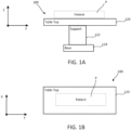
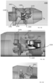
- a surgical table 100 includes a table top 120, a table support 122 and a table base 124.
- the table top 120 has an upper surface on which a patient P can be disposed during a surgical procedure, as shown schematically in FIG. 1A .
- the table top 120 is disposed on the support 122, which can be, for example, a pedestal, at a suitable height above the floor.
- the support 122 may provide for movement of the table top 120 in a desired number of degrees of freedom, such as translation in the Z-axis (height above the floor), Y-axis (along the longitudinal axis of the table), and/or X-axis (along the lateral axis of the table), and/or rotation about the Z, Y, and/or X-axes.
- the table top 120 may also include multiple sections that are movable relative to each other along / about any suitable axes, e.g., separate sections for each of the torso, one or both legs, and/or one or both arms, and a head support section.
- Movement of the table top 120 and/or its constituent sections may be performed manually, driven by motors, controlled remotely, or through any other suitable means.
- the support 122 for the table top may be mounted to the base 124, which can be fixed to the floor of the operating room, or can be movable relative to the floor, e.g., by use of wheels on the base 124.
- the height of the support 122 can be adjusted, which together with, for example, the motion (e.g., axial (longitudinal) or lateral motion) of the table top 120, can allow for the table top 120 to be positioned at a desired surgical site at a certain height above the floor (e.g., to allow surgeon access) and a certain distance from the support 120.
- This also can allow robotic arms (e.g., arms 130 discussed below) coupled to the table 100 to reach a desired treatment target on a patient P disposed on the table top 120.
- one or more robotic arms 130 can be disposed in a desired operative position relative to a patient disposed on the table top 120 of the surgical table 100 (also referred to herein as "table").
- the robotic arm(s) can be used to perform a surgical procedure on a patient disposed on the surgical table 100.
- the distal end of each robotic arm can be disposed in a desired operative position so that a medical instrument coupled to the distal end of the robotic arm can perform a desired function.
- each robotic arm 130 can include a distal end portion 137 and a proximal end portion 136.
- the distal end portion 137 (also referred to herein as “operating end”) can include or have coupled thereto a medical instrument or tool 115.
- the proximal end portion 136 (also referred to herein as the "mounting end portion” or “mounting end”) can include the coupling portion to allow the robotic arm 130 to be coupled to the table 100.
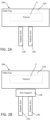
- the robotic arm 130 can include two or more link members or segments 110 coupled together at joints that can provide for translation along and/or rotation about one or more of the X, Y and/or Z-axes (shown, for example, in FIGS. 1A and 1B ).
- the coupling portion of the robotic arm 130 can include a coupling mechanism 139.
- the coupling mechanism 139 can be disposed at the mounting end 136 of the arm 130 and may be coupled to a segment 110 or incorporated within a segment 110.
- the robotic arm 130 also includes a target joint J1 disposed at or near the mounting end 136 of the robotic arm 130 that can be included within the coupling mechanism 139 and/or the coupling portion or can be disposed on a link or segment 110 of the robotic arm 130 that is coupled to the coupling portion.
- the target joint J1 can provide a pivot joint to allow a distal segment of the robotic arm 130 to pivot relative to the table 100.
- the robotic arm 130 can be moved between various extended configurations for use during a surgical procedure, as shown in FIG. 1C , and various folded or collapsed configurations for storage when not in use, as shown in FIG. 1D .
- a robotic arm for use in performing a surgical procedure may be releasably coupled to a surgical table.
- robotic arms can be coupled at a fixed location on the table or can be coupled such that the robotic arms can be movable to multiple locations relative to the table top.
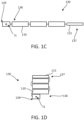
- robotic arms 230 can be coupled to a table top 220 of a surgical table 200.
- the surgical table 200 can be the same or similar in structure and function to the surgical table 100 described above.
- the table top 220 has an upper surface on which a patient P can be disposed during a surgical procedure.
- the robotic arms 230 can be permanently or releasably coupled, in a fixed or movable location, to an arm adapter that is coupled to or separate from the surgical table.
- an arm adapter 246 can be coupled to or separate from but engageable with or couplable to the table top 220.
- the robotic arms 230 can be coupled to the arm adapter 246.
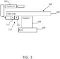
- a coupler 310 may be provided to couple a robotic arm 320 to a surgical table 300.
- the coupler 310 as described herein is usable with any of the surgical tables and robotic arms (e.g., surgical table 100, 200, robotic arms 130, 230), and methods described herein.
- the coupler 310 can include a first portion 312 (e.g., arm adapter) such as a terminal base portion A for a robotic arm.
- the coupler 310 can include a second portion 314 such as a base portion B for mounting to the surgical table 300.
- the robotic arm 320 can be coupled to the first portion 312 and the table top 302 can be coupled to the second portion 314 prior to coupling of the first portion 312 to the second portion 314.
- the coupling of the robotic arm 320 to the surgical table 300 can allow the robotic arm coupled to the table 300 to reach a desired treatment target on a patient disposed on the table top 302.
- the first portion 312 and the second portion 314 may further include electrical power and data connectors. It should be appreciated that the first portion 312 and second portion 314 may be reversed such that the first portion 312 couples to the table 300 and the second portion 314 couples to the robotic arm 320.
- a surgical table 300 includes a table top 302, a table support 304 and a table base 306.
- the table top 302 has an upper surface on which a patient can be disposed during a surgical procedure, as shown schematically in FIG. 1A .
- the table top 302 is disposed on the support 304, which can be, for example, a pedestal, at a suitable height above the floor.
- the support 302 may provide for movement of the table top 302 in a desired number of degrees of freedom, such as translation in the Z-axis (height above the floor), Y axis (along the longitudinal axis of the table), and/or X-axis (along the lateral axis of the table), and/or rotation about the Z, Y, and/or X axes.
- the support 304 for the table top 302 may be mounted to the base 306, which can be fixed to the floor of the operating room, or can be movable relative to the floor, e.g., by use of wheels on the base 306.
- one or more robotic arms 320 shown schematically in FIG. 1C and 1D ) can be disposed in a desired operative position relative to a patient disposed on the table top 302 of the surgical table 300.
- FIG. 4A is a side view of an embodiment of a coupler 400 including a first portion 410 and a second portion 420. Coupling of the first portion 410 and second portion 420 forms a secure mating connection where six degrees of freedom are constrained.
- the secure mating connection y-axisconstrains a translation in the Z-axis, a Y axis, and/or X-axis, and/or rotation about the Z, Y, and/or X-axes, of the first portion 410 with respect to the second portion 420.
- the first portion 410 includes a handle 454 configured to lock and secure the coupling between the first portion 410 and second portion 420, and a set of V-grooves 432 configured to contact a corresponding kinematic mount 430, as described herein.
- the second portion 420 includes a post 422 (e.g., locking post) that may be translated along a Y axis to mate with the first portion 410. Coupling the post 422 to the first portion 410 may constrain translation along the Y axis.
- FIG. 4B illustrates the X-axis, Y axis, and Z-axis relative to the coupler 400.
- the second portion 420 may further include a set of kinematic mounts 430 that may include at least three kinematic mounts that protrude from a surface of the second portion 420 and are configured to slide into and mate with a corresponding V-groove 432.
- the kinematic mounts 430 and V-grooves 432 are configured to locate, constrain, and support the coupling between the first portion 410 and second portion 420.
- the kinematic mounts 430 may include a spherical or semi-spherical shape.
- the kinematic mounts 430 may be equally spaced apart around the post 422 of the second portion 420.
- the V-grooves 432 may form a V-shaped cut-out in the first portion 410 and may further include a groove at a vertex of the "V".
- the sphere-in-groove mating connection between the kinematic mounts 430 and V-grooves 432 may constrain translation in the X-axis and Z-axis and constrain rotation about the X-axis, Y axis, and Z-axis.
- the second portion 420 may include one or more alignment protrusions 434 configured to contact and slide into and mate with a corresponding hole (not shown) in the first portion 410.
- the alignment protrusion 434 is asymmetrical in that alignment of the protrusion 434 with the first portion 410 is configured to prevent a user from inserting the first portion 410 incorrectly into the second portion 420. This process may be referred to herein as registration.
- the shape of the alignment protrusion 434 shown is having a semispherical end, but is not particularly limited.
- FIG. 4C illustrates the second portion 420 partially inserted into the first portion 410.
- the alignment protrusion 434 and alignment hole 436 are oriented so as to permit the post 422 of the second portion 420 to be fully translated into the first portion 410. Otherwise, the alignment protrusion 434 contacts the housing of the first portion 410 to create a gap between the first portion 410 and the second portion 420 that prevents their coupling.
- FIG. 4D illustrates a perspective view of the first portion 410 aligned and having an initial engagement with the second portion 420.
- the handle 454 e.g., lock handle
- the handle 454 is in a first position corresponding to a first position (e.g., unlocked position) of the coupler 400.
- a user may rotate the handle 454 into a second position (e.g., locked position) to transition the coupler 400 from a first configuration (e.g., unlocked state or position) to a second configuration (e.g., locked state or position).
- each of the kinematic mounts 430 are aligned with and engaged to contact and mate with a corresponding V-groove 432.
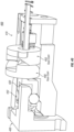
- FIG. 4F is a cross-sectional side view of the initial translation of the second portion 420 into the first portion 410. From this view, it can be seen that first portion 410 includes a first end 456 (the end that attaches to the robotic arm) and a second end 458 (the end that attaches to second portion 420), and an interior cavity 464 formed within first portion 410, between the first and second ends. An opening to the interior cavity is formed through the second end 458.
- the first portion 410 further includes a ball bearing holder 440 (e.g., draw bar) coupled to a set of ball bearings 442, which are positioned within interior cavity 464.
- a ball bearing holder 440 e.g., draw bar
- the set of ball bearings 442 may include four or more ball bearings equally spaced apart along a circumference of the ball bearing holder 440.
- the handle 454 may be coupled to a pair of cams including a first face cam 450 and a second face cam 452.
- a set of Belleville washers 460 may be coupled a shaft of the ball bearing holder 440.
- the post 422 of the second portion 420 may include a first surface 423 (e.g., lead in taper) configured to permit misalignment during translation and sliding of the post 422 into the ball bearing holder 440.
- the post may further include a second surface 424 (e.g., angled face) configured to press against the ball bearings 442 when the mating connection is locked.
- the first surface 423 and second surface 424 experience Hertzian stresses based on the curvature of the surfaces.
- the curvature and material properties, along with the ball bearing 442 diameter and material may be configured to generate contact conditions that do not deteriorate the surfaces.
- the ball bearing holder 440 is configured to hold the ball bearings 442 and surround the post 422.
- the ball bearing holder 440 is configured to translate along the Y axis relative to a housing of the first portion 410 when the face cams are rotated by the handle 454.
- the translation of the ball bearing holder 440 into the first portion 410 presses the ball bearings 442 into surfaces in the first portion 410, surfaces in the ball bearing holder 440, and surfaces in the post 422.
- the ball bearing holder 440 may include a lip on each ball bearing pocket configured to retain the ball bearing 442 within the holder 440 when the ball bearings 442 are not in contact with the post 422. These surfaces experience Hertzian stresses based on the curvature of the surfaces.
- the curvature and material properties, along with the ball bearing 442 diameter and material may be configured to generate contact conditions that do not deteriorate the surfaces.
- the ball bearings 442 move within a predetermined range within the ball bearing holder 440 and serve as a locking mechanism to apply forces to both the first portion 410 and second portion 420 to securely lock them together and form a coupling between the first portion 410 and the second portion 420.
- FIG. 4G is a cross-sectional perspective view of the coupler 400 in a locked state (or locked position) illustrating the first face cam 450 and second face cam 452 in a maximally separated position where the ball bearing holder 440 is maximally translated into the first portion 410 and the ball bearings 442 have engaged the post 442 and housing 410 to securely lock and couple the first portion 410 to the second portion 420 (e.g., the locked position).
- the first face cam 450 and second face cam 452 are coupled to the ball bearing holder 440 such that translation of the face cams along the Y-axis also translates the ball bearing holder 440 along the Y-axis.
- Each of the face cams may include a profile that converts rotational motion (e.g., from motion of handle 454) about the Y-axis into translational motion about the Y-axis.
- the handle 454 may be threaded directly into one of the face cams, thereby allowing for a torque advantage when the face cams are rotated into the locked position.
- the face cams may include a variable cam profile having a first and second profile.
- a first profile may be configured to permit relatively greater translation and a relatively lower axial force advantage.
- a second profile may be configured to permit a relatively lower translation and a relatively greater axial force advantage.
- the first profile may be steep and a second profile may be shallow.
- the varying cam profile may be configured to permit a large translation (e.g., 0.25") followed by a very small (e.g., 0.04") translation.
- the face cams may include a compound profile that decreases the pitch as the ball bearing holder reaches full engagement (e.g., as the ball bearing holder translates towards a lock position.
- the face cams may include a thrust bearing to reduce friction on the outer surfaces of the face cam.
- the face cams may include lobes configured to distribute pressure evenly.
- different portions of the face cams may be made of different materials in order to variably change friction and/or strength of the face cams.
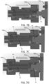
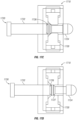
- FIGS. 4H-4L are cross-sectional side views of the coupler 400 in various states (e.g., unlocked and locked).
- FIG. 4H illustrates an initial engagement state where surfaces of the post 422 are in contact with the ball bearing 442 within the ball bearing holder 440.
- the handle 454 (not shown) and the face cams 450, 452 are in an unlocked position.
- FIG. 4I illustrates a locked position of the coupler 400 after rotation of the handle 454 (not shown) to a locked position.
- the rotation of the handle 454 is converted into translational motion of the face cams 450, 452 along the Y-axis such that the first face cam 450 and the second face cam 452 are maximally separated.
- FIG. 4J is a detailed view of the locking mechanism of the coupler 400.
- the ball bearing holder 440 in a locked position translates the ball bearings 442 into the first portion 410 to make contact with a contact surface 411 of the first portion 410, a ball bearing lip 441 of the ball bearing holder 440, and a second surface 424 of the post 422.
- the coupler 400 is self-locking in that the coupling will not become disengaged without user input.
- FIG. 4K illustrates a set of Belleville washers 460 coupled to a threaded shaft of the ball bearing holder 440.
- the Belleville washers 460 may be configured to apply a holding force to ball bearing holder 440. In some embodiments, the Belleville washers may apply between about 90.7 kg force and about 136.1 kg force.
- FIG. 4L illustrates a spring 462 (e.g., compression spring) coupled between an end of the housing of the first portion 410 and the Belleville washers 460.
- the spring 462 may be configured to provide the spring force to reset the position of the ball bearing holder 440 and hold the handle 454 in the unlocked position.
- the spring 462 may be configured to bias the ball bearing holder 440 into an unlocked position such that when a user rotates the handle 454 to an unlocked position, the ball bearing holder 440 will translate along the Y-axis towards an initial position such as shown in FIG . 4F .
- the Belleville washers 460 may be configured to vary a force of the lock.
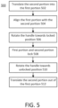
- FIG. 5 is a flowchart of a method 500 of coupling a robotic arm to a surgical table, such as by using any of the couplers described herein.
- the method 500 includes translating at 502 a second portion (e.g., robotic arm base portion) of a coupler into a first portion of the coupler (e.g., mounting portion of a surgical table top) ( FIG . 4F ).
- a post of the second portion may begin to align at 504 as the post moves into the first portion ( FIG . 4C ).
- the locking mechanism of the first portion e.g., ball bearing holder, ball bearings, face cams, handle
- the handle When the post is in an initial engagement state with the ball bearing holder ( FIG . 4H ), the handle may be rotated at 506 to rotate the two face cams.
- the lock may rotate about 90 degrees from an unlocked position to a locked position.
- the face cams move apart and translate the ball bearing holder further into the first portion ( FIG. 4I ).
- the ball bearing holder engages the set of ball bearings so as to press the ball bearings against surfaces of the first portion and the second portion ( FIG. 4J ).
- the pressing force locks at 508 the first and second portions together.
- a set of kinematic mounts engage with corresponding V - grooves to precisely align the first and second portions ( FIG. 4E ).
- a user may rotate the handle at 510 towards the unlocked position. This rotates the face cams towards each other and translates the ball bearing holder towards the second portion, thereby releasing the force between the ball bearings and the housing of the first portion. With the lock disengaged, the second portion may be fully decoupled from the first portion by translating the second portion out of the first portion at 512.
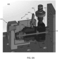
- FIGS. 6A-6C are perspective views of an embodiment of a coupler 600 driven by a motor and having a manual coupling mechanism that may be used to couple and decouple in cases where power is lost and/or emergency operation.
- the coupler 600 may include a first portion 610 and a second portion 620. Coupling of the first portion 610 and the second portion 620 forms a secure mating connection where six degrees of freedom are constrained.
- the second portion 620 may include a post 622 configured to surround the first portion 610. The post 622 may be translated along a Y-axis to mate with the first portion 610 to constrain the translation along the Y-axis.
- the first portion 610 may include a set of ball bearings 640, a cam 630 coupled to a bushing 632, and a shaft 634.
- the set of ball bearings 640 may include four or more ball bearings equally spaced apart along a circumference of the first portion 610.
- the set of ball bearings 640 may be moved by a locking mechanism configured to securely engage and lock the first portion 610 to the second portion 620.
- the cam 630 is configured to translate along the Y-axis relative to a housing of the first portion 610 when driven by a motor and/or handle 650.
- the post 622 and the cam 630 experience Hertzian stresses based on the curvature of those surfaces.
- the curvature and material properties, along with the ball bearing 640 diameter and material may be configured to generate contact conditions that do not deteriorate those surfaces. Movement of a cam 630 into a locked position will position the set of ball bearings 640 in holding contact force between surfaces of the post 622 of the second portion and surfaces of the cam 630.
- the cam 630 and the bushing 632 may be configured to be slidable along the shaft 634. Movement of the cam 630 along the shaft 634 may vary a contact force of the set of ball bearings 640 against a contact surface of the post 622 when the first portion 610 and the second portion 620 are translated into each other.
- a contact surface of the post 622 may include a post lip 624 configured to retain the ball bearings 640 within the second portion 620.
- the ball bearings 640 move within a predetermined range first portion 610 and serve as a locking mechanism to apply forces to both the first portion 610 and second portion 620 to securely lock them together and form a coupling between the first portion 610 and the
- the cam 630 may be driven by a worm gear including a worm wheel 660 and worm 662) using a motor 670 to couple and decouple the first portion 610 and the second portion 620.
- the motor 670 may be, for example, a brushless DC motor.
- the first portion 610 may include a handle 650 configured to permit a user to actuate in order to slide the cam 630 along the shaft 634 and engage or release the set of ball bearings 640 from contact with a contact surface of the post 622.
- the handle 650 may rotate between a locked position and an unlocked position and transition the coupler 600 between a locked configuration and an unlocked configuration.
- FIG. 6A illustrates a locked position of the coupler 600. In the locked position, the contact between the ball bearings 640 and the post 622 of the second portion 620 and the cam 630 securely engage and lock the first portion 610 to the second portion 620.
- Rotation of the handle 650 towards the unlocked position is converted into translational motion of the cam 630 along the Y-axis to disengage contact between the ball bearings 640 and surfaces of the post 622 and the cam 630.
- a spring 664 may be coupled between the bushing 632 and the worm wheel 660 and configured to provide the spring force to reset the position of the cam 630 into an unlocked position where the cam 630 is biased towards the worm gear.
- the post 622 may include one or more relief cuts 626 that may be configured to provide a desired level of holding force between the first portion 610 and the second portion 620. For example, a wider and/or longer gap in the relief cuts 626 may reduce the maximum holding force between the first portion 610 and the second portion 620.
- the second portion 620 may further include a post lip 624.
- the coupler 600 may include kinematic mounts, V-grooves, and/or alignment elements as described herein.
- FIG. 7A is a cross-sectional perspective view of an embodiment of a coupler 700.
- the coupler 700 includes a first portion 710 having an outer housing 712 and a first portion threading 714.
- the coupler 700 also includes a second portion 720 having a post 722. That may be translated along a Y-axis to mate with the first portion 710 to constrain translation along the Y-axis. Coupling of the first portion 710 and the second portion 720 forms a secure mating connection where six degrees of freedom are constrained.
- the first potion 710 may include a collet 750 configured to lock and secure the coupling between the first portion 710 and the second portion 720.
- the first portion 710 includes a ball bearing holder 740 configured to receive, engage, and lock with the post 722.
- the ball bearing holder 740 is configured to hold the ball bearings 742 and surround the post 722.
- the ball bearing holder 740 is configured to translate along the Y-axis relative to a housing of the first portion 710 when the collet 750 is rotated. The translation of the ball bearing holder 740 into the first portion 710 presses the ball bearings 742 into the first portion 710, the ball bearing holder 740, and the post 722.
- the ball bearing holder 740 may include a lip on each ball bearing pocket configured to retain the ball bearing 742 within the holder 740 when the ball bearings 742 are not in contact with the post 722. These surfaces experience Hertzian stresses based on the curvature of the surfaces. The curvature and material properties, along with the ball bearing 742 diameter and material may be configured to generate contact conditions that do not deteriorate the surfaces.
- the ball bearings 742 move within a predetermined range within the ball bearing holder 740 and serve as a locking mechanism to apply forces to both the first portion 710 and second portion 720 to securely lock them together and form a coupling between the first portion 710 and the second portion 720.
- a set of Belleville washers 760, a lock collar 746, and a thrust bearing 744 may be coupled to the ball bearing holder 740.
- the collet 750 may be configured to rotate about the first portion 710 so as to lock and unlock the post 722 from the ball bearing holder 740.
- An outer surface of the collet 750 may be a locking knob that the user can rotate to couple and decouple the first portion 710 and second portion 720.
- FIGS. 7B-7D are cross-sectional side views of the coupler 700 in different coupling states.
- the set of Belleville washers 760 are compressed and the knob portion (of the collet 750) is turned in.
- the second portion 720 is being translated into the first portion 710 but has not made contact with the ball bearing holder 740.
- FIG. 7C the first portion 710 and second portion 720 have made an initial engagement where the post 722 contacts the ball bearing holder 740.
- the collet 750 is in a first position corresponding to an unlocked position of the coupler 700.
- the set of Belleville washers 760 are fully compressed and the knob portion of the collet 750 is turned in.
- the collet knob is rotated so as to be turned out so as to draw the ball bearing holder 740 into the first portion 710 and lock the post 722 to the first portion 710.
- the set of Belleville washers 760 are at a work load compression. Both the post 722 and the first portion 711 are held by a holding force using a set of ball bearings 742.
- the set of ball bearings 742 may include four or more ball bearings equally spaced apart along a circumference of ball bearing holder 740.
- the coupler 700 may include kinematic mounts, V-grooves, and/or alignment elements as describe herein.
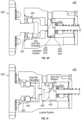
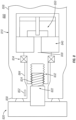
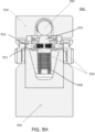
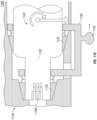
- FIG. 8 is a cross-sectional side view of an embodiment of a coupler 800 driven by a motorized locking mechanism that may generate high forces to ensure the coupling is constrained and maintained in six degrees of freedom even in the presence of external loads (e.g., robotic arm static and inertial loads during a surgical procedure).
- the coupler 800 may include a first portion 810 and a second portion 820. Coupling of the first portion 810 and second portion 820 forms a secure mating connection where six degrees of freedom are constrained. From this view, it can be seen that first portion 810 includes a first end 856 (the end coupled to the robotic arm) and a second end 858 (the end coupled to second portion 820), and an interior cavity 864 formed within first portion 810, between the first and second ends.
- the first portion 810 may include a locking mechanism coupled to a drive mechanism configured to lock and secure the coupling between the first portion 810 and the second portion 820.
- the second portion includes a post 822 that may be translated along a Y-axis to mate with the first portion 810 to constrain translation along the Y-axis.
- the post 822 includes a lead screw 824 that may be coupled to a corresponding threaded portion 832 of a rotatable collet 830.
- a motor 850 may drive the collet 830 to rotate about the lead screw 824 in a first direction so as to translate the lead screw 824 into the first portion 810 along the Y-axis.
- the collet 830 may be engaged with the post 822 to securely lock and couple the first portion 810 to the second portion 820.
- Rotation of the collet 830 in a second direction opposite the first direction may translate the lead screw 824 out of the first portion 810 along the Y-axis.
- the pitch angle of the lead screw 824 may be between about 2 degrees and about 30 degrees. In some embodiments, the pitch angle of the lead screw 824 may be between about 10 degrees and about 15 degrees. In some embodiments, the pitch angle of the lead screw 824 may be configured to prevent the lead screw 824 from being backdriven.
- the motor 850 may be coupled to a gearbox 840 and configured to rotate the collet 830.
- the collet 830 may be coupled to one or more bearings 834.
- the bearings 834 may be, for example, a deep groove ball bearing.
- the gearbox 840 may be, for example, a planetary or harmonic gear box and may have a gear ratio of about 20 to about 200.
- the motor 850 may be, for example, a brushless DC motor.
- the motorized locking mechanism may generate a force of at least 500 N. In some embodiments, the motorized locking mechanism may generate a force of at least 1400 N.
- the motor 850 may be coupled to a controller (not shown) configured to receive input commands from a user.
- a robotic arm may include a switch that may input a coupling command to lock and unlock the first portion 810 from the second portion 820 by driving the lead screw in either direction, thereby attaching and detaching the robotic arm from a surgical table.
- the switch may be provided on a surgical table, medical cart, and/or portable computing device.
- the coupler 800 may include a connection sensor 852 configured to detect coupling and decoupling between the first portion 810 and the second portion 820.
- the connection sensor may include one or more of a force sensor, Hall effect sensor, and electrical switch located on either the first portion 810 and the second portion 820 (e.g., at an interface between the first portion 810 and the second portion 820).
- the connection sensor may include an encoder on the motor 850.
- a controller may be configured to drive the collet 830 using the motor 850 until a coupling or decoupling has been detected.
- the coupler 800 may include kinematic mounts, V-grooves, and/or alignment elements as described herein.
- the motorized locking mechanism of coupler 800 may reduce user error in coupling the first portion 810 to the second portion 820 including partial coupling and decoupling, usability risk (e.g., non-intuitive use), and increase safety (e.g., robotic arm falling to the floor on onto a user's foot or leg).
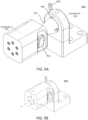
- FIG. 9A is a perspective side view of an embodiment of a coupler 900.
- the coupler 900 can include a first portion 910 such as a base portion for mounting to a surgical table (e.g., surgical table 300).
- the coupler 900 can include a second portion 920 (e.g., arm adapter) such as a terminal base portion for a robotic arm. Coupling of the first portion 910 and second portion 920 forms a secure mating connection where six degrees of freedom are constrained.
- the first portion 910 includes a handle 940 configured to lock and secure the coupling between the first portion 910 and second portion 920, and an alignment protrusion 960 configured to contact a corresponding alignment hole (not shown), as described herein.
- the first portion 910 includes a cone 930 that may be translated along a Y-axis to mate with a conical receiving hole 912 ( FIG. 9D ) of the second portion 920 to constrain translation along the Y-axis.
- FIG. 9B illustrates the X-axis, Y-axis, and Z-axis relative to the coupler 900. It should be appreciated that the first portion 910 and second portion 920 may be reversed such that the first portion 910 couples to a surgical table and the second portion 920 couples to a robotic arm.
- the first portion 910 may include one or more alignment protrusions 960 configured to contact and slide into and mate with a corresponding alignment hole 962 in the second portion 962.
- the alignment protrusion 960 is asymmetrical in that alignment of the protrusion 960 with the second portion 920 is configured to prevent a user from inserting the first portion 910 incorrectly into the second portion 920. This process may be referred to herein as registration.
- the shape of the alignment protrusion 960 is shown having a cylindrical shape, but is not particularly limited.
- the alignment protrusion 960 may include a spring loaded/split pin.
- FIG. 9D illustrates the alignment protrusion 960 of the first portion 910 aligned with the alignment hole 962 of the second portion 920 so as to permit the cone 930 to be fully translated into the second portion 920. Otherwise, the alignment protrusion 960 contacts the housing of the second portion 920 to create a gap between the first portion 910 and the second portion 920 that prevents their coupling.
- the cone 930 is configured to provide a large surface area to form a mechanical coupling having rigidity.
- the cone 930 is configured to couple the first portion 910 and second portion 920 so as to constrain translation in the X-axis and Y-axis, and constrain rotation about the X-axis and Z-axis.
- the surface of the cone 930 forms mating surfaces that may have tight tolerances and a surface finish ensuring proper contact with the second portion 920.
- the contact surface may include a surface roughness configured to increase friction between the first portion 910 and the second portion 920.
- a taper angle of the cone 930 may be configured for low release forces while maintaining high rigidity of the coupling.
- the cone 930 may have a taper angle of about 14 degrees.
- the cone 930 may include edges or planes that contact the alternating mating surface.
- a pin 934 may be disposed at a nose of the cone 930 and may be configured to protrude from and recess into a surface of the cone 930. When the handle 940 is rotated to an unlock position, the pin may be configured to protrude from the cone 930 to aid in the release and translation of the second portion 920 away from the first portion 910 by pushing the first portion 910 and second portion 920 away from each other in the event that they remain in contact due to friction.
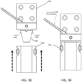
- FIG. 9C illustrates a side view of the first portion 910 and second portion 920.
- the cone 930 may include two or more catches 950 configured to constrain translation of the second portion 920 along the Y-axis.
- the catches 950 may be disposed along opposite lateral sides of the conical taper of the cone 930.
- the catches 950 may be configured as an initial locking mechanism (e.g., spring catch) to prevent a robotic arm attached to the second portion 920 from falling out and away from the cone 930 of the first portion 910.
- the catch 950 may include an angled, flat surface configured to slide easily over a surface of a conical hole 912.
- the catch 950 may include a tapered portion configured to hold the first portion 910 against the second portion 920.
- the second portion 920 includes a switch 952 having a corresponding catch 950 configured to move the catches 950 from a first configuration to a second configuration.
- the catches 950 may be biased to protrude from the cone 930 in the first configuration and be recessed into the cone 930 in the second configuration.
- FIG. 9E shows the second portion 920 being translated over the cone 930.
- the catches 950 make contact with the surface of the conical hole 912 and are recessed into the cone 930.
- the catches 950 advanced over corresponding axial grooves 932 ( FIG.
- FIG. 9D allows the catches 950 to protrude out in the first configuration to thereby couple and secure the first portion 910 to the second portion 920 in an initial lock state, as shown in FIG. 9F .
- FIG. 9G is a perspective view of the first portion 910 and second portion 920 in the initial lock state.
- the handle 940 is in an unlocked state throughout the steps shown in FIGS. 9D-9G .
- FIGS. 9H and 9M shows a first surface 951 and a second surface 953 of the catch 950.
- the first surface 951 may be an angled, flat surface having an angled similar to that of the taper angle of the cone 930.
- the first surface 951 may be configured to permit the catch 950 to slide easily over a surface of a conical hole 912. As the first surface 951 translates through the conical hole 912 of the second portion 920, the catch 950 is recessed into the cone 930.
- the second surface 953 may a tapered portion configured to hold the first portion 910 against the second portion 920.
- the second surface 953 of the catch 950 may include an anti-release angle 1044 configured to prevent the catch 950 from decoupling from the second portion 920 when the catch 950 is in a protruding configuration.
- the catches 950 may be configured to be biased towards the protruding configuration.
- the catches 950 may include a camming surface configured to contact a corresponding surf ace such that by wedging the catches outward rather than being pulled back, the first portion 910 and second portion 920 may be secured and locked together.
- the camming surface may include an angle surface, a ball and socket surface, and/or the like.
- FIG. 9H illustrates a set of Belleville washers 958 coupled to the catches 950 and shuttle 970.
- the Belleville washers 958 may be configured to apply a holding force to the catch 950. In some embodiments, the Belleville washers 958 may apply between about 59.0 kg force and about 104.3 kg force.
- the Belleville washers 958 may be configured to vary a force of the lock (e.g., handle 940, cam 942, and shuttle 970). In some embodiments, a precompression force of the Belleville washers 958 may be adjusted using an auxiliary input.
- the handle 940 coupled to the cam 942 is illustrated in FIGS. 9H and 9M .
- the cam 942 is configured to rotate in response to rotation of the handle 940 between unlocked and locked positions. Rotation of the cam 942 towards a locked position applies contact forces to the shuttle 970 disposed within the cone 930. As the handle 940 rotates through its arc, the cam 942 applies force against the shuttle 970 of the first portion 910 to bring the first portion 910 and second portion 920 together and securely lock the first portion 910 to the second portion 920 with high rigidity. When the handle 940 is in the locked position, the first portion 910 and second portion 920 are securely engaged and locked to each other.
- the first portion may include a motorized locking mechanism as described herein, in place of the handle 940 and cam 942.
- the cam 942 may be rotated indirectly through, for example, a set of right angle gears or rotational motion about an axis separate from the cam 942 axis.
- FIG. 9I - FIG. 9L illustrates front, side, top, and perspective views, respectively, of the switches 952.
- a switch 952 may include a release point 956 configured to make contact with and push a corresponding axial switch 950 into the recessed second configuration.
- the switch 952 may rotate about a hinge 1054 when actuated. In some embodiments, the switches 952 may be spaced apart by about 8.89 cm.
- Each switch 952 may include a torsion spring configured to bias the switch 952 to an initial, reset position.
- the first portion 910 and the second portion 920 may each include an electrical interface 938 to provide a power and/or data connection between the first portion 910 and the second portion 920.
- the electrical interface may include one or more of a spring contact pin, wiping contacts, a fiber optic interface, transformers, or any other power and/or data connector.
- the electrical interface of the first portion 910 may be disposed on the tapered surface of the cone 930 or on the base flange of the first portion 910 that supports the cone 930.
- one or more of the catches 950 may include an electrical interface since the catches 950 contact the second portion 920.
- the coupler 900 may include one or more connection sensors 936, as described herein, and configured to detect coupling and decoupling between the first portion 910 and the second portion 920.
- connection sensors may be configured to detect one or more of an amount of force the catches 950 are holding, a location of the catches 950 (e.g., amount that the catches have moved), and a contact state between the cone 930 and the second portion 920.
- one or more of the first portion 910 and second portion 920 may include a dampener configured to vibrationally isolate the first portion 910 from the second portion 920.
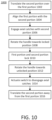
- FIG. 10 is a flowchart of a method 1000 of coupling a robotic arm to a surgical table, such as by using any of the couplers described herein.
- the method 1000 includes translating at 1002 a second portion (e.g., robotic arm base portion) of a coupler over a first portion of the coupler (e.g., mounting portion of a surgical table top) ( FIG. 9E ).
- a conical taper of the first portion may provide initial alignment.
- the second portion at 1004 is further aligned with the first portion as the second portion is translated over a cone of the first portion by aligning corresponding alignment elements on each of the first and second portions.
- the locking mechanism of the first portion (e.g., catches) will not engage with the second portion if the alignment element(s) of the first portion are not aligned with the second portion.
- the catches are engaged with the second portion at 1006 ( FIG. 9F ).
- This initial coupling of the catches to the second portion is self-locking in that the coupling will not become disengaged (e.g., released) without user input (e.g., user actuation of a switch).
- the first portion and second portion are coupled in an initial engagement state such that the second portion is unable to fall away from the first portion if the second portion was unsupported by a user.
- a handle While in the initial engagement state, a handle may be rotated at 1008 to rotate a two position cam of the first portion to apply contact forces to a shuttle disposed within the cone. As the handle rotates through its arc, the cam applies force against the shuttle of the first portion to bring the first portion and second portion together and securely lock the first portion to the second portion with high rigidity. In some embodiments, the handle may rotate about 90 degrees from an unlocked position to a locked position. The first portion and second portion are locked at 1010.
- the handle To disengage the first portion from the second portion, the handle must be rotated to an unlock position before a catch switch is actuated. Accidental decoupling is reduced by required both locks to be decoupled by a user.
- the handle may be rotated at 1012 towards an unlocked position to rotate the cam and decouple it from the shuttle. Rotation of the handle to the unlocked position does not fully decouple the first portion and second portion, and permits the user to support the mass of a robotic arm coupled to the second portion. Actuation of one or more switches at 1014 recesses the catches into the cone and allows the second portion to translate at 1016 out and away from the cone of the first portion.
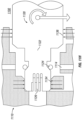
- FIGS. 11A , 11E , and 11H are cross-sectional side views of embodiments of a coupler 1100 including a first portion 1110 and a second portion 1120. Coupling of the first portion 1110 and second portion 1120 forms a secure mating connection where six degrees of freedom are constrained.
- the first and second portion may each include an electrical interface 1126 to provide power and data through the coupler 1100.
- the first portion 1110 includes a ball bearing 1112 coupled to a spring 1114 configured to couple the first portion 1110 to the second portion 1120.
- a positive lock may be further coupled to spring 1114 to prevent spring back.
- the second portion 1120 includes a post 1122 that may be translated along a Y-axis to mate with the first portion 1110.
- the second portion 1120 may include a first surface 1123 and a second surface 1124.
- the second surface 1124 may have a steeper angle relative to the first surface 1123.
- a radial clamp 1130 may be disposed around the second portion 1120. Coupling of the post 1122 to the first portion 1110 may constrain translation along the Y-axis.
- FIG. 11A illustrates the first portion 1110 aligned and having an initial engagement with the second portion 1120.
- the post 1122 of the second portion 1120 may include the first surface 1123 (e.g., lead in taper) configured to permit misalignment during translation and sliding of the post 1122 into the first portion 1110.
- the post 1122 may further include a second surface 1124 (e.g., angled face) configured to press against the ball bearings 1124.
- the first surface 1123 and second surface 1124 experience Hertzian stresses based on the curvature of the surfaces.
- the curvature and material properties, along with the ball bearing 1124 diameter and material may be configured to generate contact conditions that do not deteriorate the surfaces.
- FIGS. 11B-11D are front cross-sectional view of the radial clamp 1130 coupled to an actuator 1140.
- the actuator 1140 may include a screw 1142 and handle 1144. A user actuating the handle 1144 may turn the screw 1142 to vary a radial compression force of the clamp 1130 on the second portion 1120.
- the actuator 1140 may be pivoted or rotated. In some embodiments, the actuator 1140 may be rotated a quarter turn to achieve a desired radial compression of clamp 1130.
- the clamp 1130 may also include one or more reliefs 1132 to distribute compression forces. The clamp compresses within a predetermined range and serve as a locking mechanism to apply forces to both the first portion 1110 and second portion 1120 to securely lock them together and form a coupling between the first portion 1110 and the second portion 1120.
- FIG. 11E illustrates a coupler 1100 including a first collet 1150 and a second collet 1152.
- the first collet 1150 may be configured to couple to an end of the second portion 1120 between the first portion 1110 and the second portion 1120.
- the second collet 1152 may be configured to couple to a base portion of the second portion 1120 between the first portion 1110 and the second portion 1120.
- the first collet 1150 and second collet 1152 are both coupled to a toggle 1160 having a handle 1162 for a user to translate along a Y-axis.
- the outer and inner surfaces of the collets may match an angle of respective first and second portions such that the collets may translate and compress between the first and second portions.
- the collets may be coupled to a set of Belleville washers to provide a predetermined compression force.
- the first collet 1150 and second collet 1152 may each include one or more slits 1151, 1153 (see FIGS. 11F- 11G ) such that translation of the toggle 1160 towards the first portion 1110 will compress the collets and secure the coupling between the first and second portions.
- the collets translate and compress within a predetermined range and serve as a locking mechanism to apply forces to both the first portion 1110 and second portion 1120 to securely lock them together and form a coupling between the first portion 1110 and the second portion 1120.
- compression of the collets at a predetermined force forms an electrical interface connection.
- FIG. 11H illustrates a coupler 1100 including a first clamp 1134 and a second clamp 1136.
- the first clamp 1134 may be configured to couple to and vary a radial compression force to an end of the second portion 1120.
- the second clamp 1136 may be configured to couple and vary a radial compression force.
- the first clamp 1134 and second clamp 1136 may be coupled to a respective first cam 1170 and second cam 1172, as shown in FIG. 11I .
- Each of the cams may be coupled to a handle and actuated together to vary a radial compression force on the second portion 1120.
- the first cam 1170 and second cam 1172 may have different profiles and may be actuated using rotary or linear motion.
- cams 1170, 1172 may allow for different timing, different compression and/or linear motion and clamping of the clamps 1134, 1136.
- Each of the clamps compresses within a predetermined range and serve as a locking mechanism to apply forces to both the first portion 1110 and second portion 1120 to securely lock them together and form a coupling between the first portion 1110 and the second portion 1120.
- compression of the radial clamp at a predetermined force forms an electrical interface connection.
- FIG. 12 is a flowchart of a method 1200 of coupling a robotic arm to a surgical table, such as by using any of the couplers described herein.
- the method 1200 includes translating at 1202 a second portion (e.g., robotic arm base portion) of a coupler into a first portion of the coupler (e.g., mounting portion of a surgical table top).
- a post of the second portion may begin to align at 1204 as the post moves into the first portion.
- the locking mechanism of the first portion e.g., radial clamp, handle, actuator, knob
- the handle When the post is in an initial engagement state against a set of ball bearings, the handle may be rotated at 1206 to compress the radial clamp. The pressing force of the radial clamp locks at 1208 the first and second portions together.
- a user may rotate the handle at 1210 towards the unlocked position. This decompresses the radial clamp, thereby releasing the force between the ball bearings and the housing of the second portion. With the lock disengaged, the second portion may be fully decoupled from the first portion by translating the second portion out of the first portion at 1212.
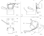
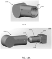
- FIGS. 13A-13D are perspective views of embodiments of a coupler 1300 including a first portion 1310 and a second portion 1320. Coupling of the first portion 1310 and second portion 1320 forms a secure mating connection where six degrees of freedom are constrained.
- the first and second portion may each include an electrical interface to provide power and data through the coupler 1300.
- the post hole 1312 may include a first electrical connector 1316 shown in FIG. 13C configured to couple to a second electrical connector 1330 shown in FIG. 13A-13C .
- the second portion 1320 includes a post 1322 that may be translated along a Y-axis to mate with the first portion 1310.
- the post 1322 may include a set of catches 1324 biased to protrude from the post 1322 in the first configuration and be recessed into the post 1322 in the second configuration.
- the first portion 1320 includes a post hole 1312 and a set of catch holes 1314 corresponding to the set of catches 1324 of the second portion 1320.
- the catches 1324 may be driven by a lead screw 1342 coupled to a motor 1340. As the lead screw 1342 is translated along a Y-axis, a linear rack 1350 coupled to the lead screw 1342 translates along a Y-axis and rotates a catch 1360 between the first and second configurations.
- This motorized locking mechanism may ensure a secure coupling between the first portion 1310 and second portion 1320.
- the second portion 1320 may include an access port 1370 (see FIG. 13D ) for a user to manually insert a tool (e.g., Allen wrench) to manually backdrive the linear rack 1350 and enable decoupling of the robotic arm from the surgical table.
- the motor 1340 may be, for example, a brushless DC motor.
- FIGS. 14A-14E are exterior views of a linear rack assembly 1400 including a linear rack 1420 and catch 1410.
- the linear rack 1420 may be dual sided in that the rack 1422 of one side (see FIG. 14C ) is interchangeable with that of the other side. In other words, the rack 1422 of FIG. 14C may be flipped and mated to be symmetric.
- the linear rack 1420 may include one or more Belleville washers to increase compliance for the catches 1410 (e.g., rotating cam claws).
- a post may be provided at one end of each rack to allow each rack to press together.
- a washer 1430 may be disposed between the mating surfaces of the racks 1422 to add compliance and spring resistance.
- the catch 1410 may include a spur gear 1412 and a cam claw 1414 separated in height by an offset 1418 as illustrated by FIGS. 14D-14E .
- the catch 1410 may rotate about an axis 1416.
- the cam claw 1414 may mate with a corresponding surface of the first portion as the catch rotates.
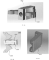
- FIGS. 15A-15C are internal perspective views of a coupler 1500, according to an embodiment.
- the coupler 1500 may include a set of three catches biased to protrude from the surface of a housing in the first configuration and be recessed into the housing in the second configuration.
- the catches 1560, 1562, 1564 may be driven by a lead screw 1542 coupled to a motor 1540.
- a linear rack 1550 coupled to the lead screw 1542 translates along a Y-axis and rotates the catch 1560, 1562, 1564 between the first and second configurations.
- the coupler 1500 may include an access port 1570 for a user to manually insert a tool (e.g., Allen wrench) to manually backdrive the linear rack 1550 and enable decoupling of the robotic arm from the surgical table.
- a tool e.g., Allen wrench
- the motor 1540 may be, for example, a brushless DC motor.
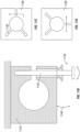
- FIGS. 16A-16B is an internal and external view of a coupler 1600 including a motorized locking mechanism.
- a first portion 1610 may include a motor 1640 coupled to a ball bearing 1650 configured to apply a holding force against a release member 1630 of a second portion 1620.
- the motor 1640 applies a downward force within a predetermined range and serves as a vibration damper and locking mechanism to apply forces to both the first portion 1610 and second portion 1620 to securely lock them together and form a coupling between the first portion 1610 and the second portion 1620.
- the release member 1630 includes a bearing surface 1634 configured to contact the ball bearing 1650.
- the bearing surface 1634 includes a tapered or ramped surface to allow the bearing 1650 to recess into the release member 1630.
- the release member 1630 may rotate about a hinge 1632.
- a pin 1642 may secure the release member 1630. However, when the pin 1642 is released, the force of gravity and the downward pressure of the bearing 1650 will cause the release member 1630 to swing open so as to release the contact force between the first portion 1610 and second portion 1620, thereby decoupling the first portion 1610 and the second portion 1620.
- FIGS. 17A-17D are schematic side views of a coupler 1700 including a translation mechanism.
- a first portion 1710 may include a carriage including a set of latches 1730 to secure a post 1722 of a second portion 1720.
- the post 1722 is translated into the first portion 1710.
- the post is further translated into the first portion 1710 for a predetermined distance, and then may be retracted to decouple the first portion 1710 and second portion 1720.
- a distal head 1724 is translated into the first portion 1710 to contact an angled first surface 1732 of the latches 1730.
- the latches may be coupled to springs 1740 biased to extend toward the other latch.
- the distal head 1724 slides through the latches such that the latches 1730 contact a second diameter portion 1723 of the post 1722.
- the post 1722 is prevented from retracting from the first portion 1710 by the contact between the latch 1730 and proximal end of the distal head 1724.
- the post 1722 includes a sliding collar 1726 that may slide along the second diameter portion 1723 of the post 1722.
- the post 1722 is further translated into the first portion 1710 such that the latch 1730 slides along the second diameter portion 1723.
- the first surface 1732 of the latch 1730 is configured to slide against the first surface 1927 of the sliding collar 1726 such that the latches 1730 hold the sliding collar 1726 in place.
- retraction of the post 1722 away from the first portion 1710 will translate the distal head 1724 in a reverse direction while the sliding collar remains fixed with respect to the latches 1730.
- the sliding collar 1726 will slide along the second diameter portion 1723 from a proximal end to a distal end.
- the opening of the latches 1730 is of a diameter such that distal head 1724 is not prevented from retracting away from the first portion 1710.
- the distal head 1724 at a proximal end may include a recess to hold the sliding collar 1726.
- FIGS. 18A-18B are side views of a grasper 1800 configured to surround and grasp a post of a coupler of any of the previous embodiments.
- the grasper 1800 includes arms 1802, 1804 operable to apply a lateral force to a longitudinal axis of the post (e.g., post 422) of the coupler (e.g., coupler 400).
Landscapes
- Engineering & Computer Science (AREA)
- Health & Medical Sciences (AREA)
- Surgery (AREA)
- Life Sciences & Earth Sciences (AREA)
- Robotics (AREA)
- Mechanical Engineering (AREA)
- Public Health (AREA)
- Animal Behavior & Ethology (AREA)
- Veterinary Medicine (AREA)
- Biomedical Technology (AREA)
- Heart & Thoracic Surgery (AREA)
- Medical Informatics (AREA)
- Molecular Biology (AREA)
- Nuclear Medicine, Radiotherapy & Molecular Imaging (AREA)
- General Health & Medical Sciences (AREA)
- General Engineering & Computer Science (AREA)
- Pathology (AREA)
- Oral & Maxillofacial Surgery (AREA)
- Manipulator (AREA)
- Accommodation For Nursing Or Treatment Tables (AREA)
Claims (5)
- Koppler (400) zum Koppeln eines Roboterarms mit einem Operationstisch, der Koppler (400) umfassend:einen ersten Abschnitt (410), der konfiguriert ist, um mit einem Roboterarm gekoppelt zu werden;einen zweiten Abschnitt (420), der konfiguriert ist, um mit einem Operationstisch gekoppelt zu werden, wobei der zweite Abschnitt (420) einen Pfosten (422) aufweist, der konfiguriert ist, um entlang einer ersten Achse des ersten Abschnitts (410) verschoben zu werden, um den zweiten Abschnitt (420) mit dem ersten Abschnitt (410) zu koppeln; undeinen Verriegelungsmechanismus, der konfiguriert ist, um eine Kopplung zwischen dem ersten Abschnitt (410) und dem zweiten Abschnitt (420) zwischen einer verriegelten Position und einer entriegelten Position zu überführen, wobei in der verriegelten Position die Bewegung des ersten Abschnitts (410) relativ zu dem zweiten Abschnitt (420) in sechs Freiheitsgraden eingeschränkt ist; undwobei der Verriegelungsmechanismus einen ersten Nocken (450), einen zweiten Nocken (452) und eine Kugellageranordnung (440, 442) umfasst, die innerhalb eines Innenhohlraums (464) des ersten Abschnitts (410) positioniert ist,wobei die Kugellageranordnung einen Kugellagerhalter (440) und ein Kugellager (442) umfasst, der Kugellagerhalter (440) umfassend einen Aufnahmehohlraum, der den Pfosten (422) aufnimmt;wobei der erste Nocken 450 und der zweite Nocken 452 mit dem Kugellagerhalter (440) gekoppelt sind,wobei eine Drehung des ersten und des zweiten Nocken (450, 452) eine Verschiebung des ersten und des zweiten Nocken (450, 452) entlang der ersten Achse bewirkt, um den Kugellagerhalter (440) entlang der ersten Achse zu verschieben, wodurch der Pfosten (422) entlang der ersten Achse in die verriegelte oder die entriegelte Position verschoben wird;wobei der Innenhohlraum (464) eine Innenkontaktoberfläche umfasst und der Pfosten (422) eine Außenkontaktoberfläche umfasst und das Kugellager (442) in der verriegelten Position die Innenkontaktoberfläche und die Außenkontaktoberfläche berührt.
- Koppler nach Anspruch 1, wobei der erste Nocken (450) und der zweite Nocken (452) Plannocken sind, die ein variables Nockenoberflächenprofil, aufweisen das konfiguriert ist, um eine Verschiebungsfunktion oder eine Axialkraftfunktion des Verriegelungsmechanismus anzupassen.
- Koppler nach Anspruch 1, wobei der Verriegelungsmechanismus ferner ein Vorspannelement (462) umfasst, das konfiguriert ist, um eine Vorspannkraft auf die Kugellageranordnung auszuüben.
- Koppler nach Anspruch 1, wobei der erste Abschnitt (410) eine axial ausgerichtete Nut (432) entlang einer Außenoberfläche umfasst und der zweite Abschnitt (420) eine kinematische Halterung (430) umfasst, die konfiguriert ist, um mit der Nut (432) zusammenzupassen, wenn der zweite Abschnitt (420) mit dem ersten Abschnitt (410) gekoppelt ist, und wobei die kinematische Halterung (430) und die Nut (432) bemessen sind, um eine Verschiebung oder Rotation des ersten Abschnitts (410) in Bezug auf den zweiten Abschnitt (420) einzuschränken.
- Koppler nach Anspruch 1, wobei der erste Abschnitt (410) ferner eine Ausrichtungsöffnung (436) umfasst und der zweite Abschnitt (420) einen Ausrichtungsvorsprung (434) umfasst, wobei der Ausrichtungsvorsprung (434) eine asymmetrische Form aufweist, die konfiguriert ist, um in einer einzigen Ausrichtung mit der Ausrichtungsöffnung (436) zusammenzupassen und eine Fehlausrichtung des ersten Abschnitts (410) in Bezug auf den zweiten Abschnitt (420) zu verhindern.
Applications Claiming Priority (3)
| Application Number | Priority Date | Filing Date | Title |
|---|---|---|---|
| US201762476816P | 2017-03-26 | 2017-03-26 | |
| US15/934,709 US11078945B2 (en) | 2017-03-26 | 2018-03-23 | Coupler to attach robotic arm to surgical table |
| PCT/US2018/024393 WO2018183212A1 (en) | 2017-03-26 | 2018-03-26 | Coupler to attach robotic arm to surgical table |
Publications (4)
| Publication Number | Publication Date |
|---|---|
| EP3579783A1 EP3579783A1 (de) | 2019-12-18 |
| EP3579783A4 EP3579783A4 (de) | 2020-12-16 |
| EP3579783B1 true EP3579783B1 (de) | 2025-05-07 |
| EP3579783C0 EP3579783C0 (de) | 2025-05-07 |
Family
ID=63581657
Family Applications (1)
| Application Number | Title | Priority Date | Filing Date |
|---|---|---|---|
| EP18774510.4A Active EP3579783B1 (de) | 2017-03-26 | 2018-03-26 | Koppler zur befestigung eines robotischen arms an einem operationstisch |
Country Status (8)
| Country | Link |
|---|---|
| US (3) | US11078945B2 (de) |
| EP (1) | EP3579783B1 (de) |
| JP (1) | JP6905162B2 (de) |
| KR (1) | KR102326102B1 (de) |
| CN (1) | CN110709025B (de) |
| AU (1) | AU2018243738B2 (de) |
| CA (1) | CA3054431C (de) |
| WO (1) | WO2018183212A1 (de) |
Families Citing this family (429)
| Publication number | Priority date | Publication date | Assignee | Title |
|---|---|---|---|---|
| US9060770B2 (en) | 2003-05-20 | 2015-06-23 | Ethicon Endo-Surgery, Inc. | Robotically-driven surgical instrument with E-beam driver |
| US20070084897A1 (en) | 2003-05-20 | 2007-04-19 | Shelton Frederick E Iv | Articulating surgical stapling instrument incorporating a two-piece e-beam firing mechanism |
| US11998198B2 (en) | 2004-07-28 | 2024-06-04 | Cilag Gmbh International | Surgical stapling instrument incorporating a two-piece E-beam firing mechanism |
| US9072535B2 (en) | 2011-05-27 | 2015-07-07 | Ethicon Endo-Surgery, Inc. | Surgical stapling instruments with rotatable staple deployment arrangements |
| US8215531B2 (en) | 2004-07-28 | 2012-07-10 | Ethicon Endo-Surgery, Inc. | Surgical stapling instrument having a medical substance dispenser |
| US11896225B2 (en) | 2004-07-28 | 2024-02-13 | Cilag Gmbh International | Staple cartridge comprising a pan |
| US11246590B2 (en) | 2005-08-31 | 2022-02-15 | Cilag Gmbh International | Staple cartridge including staple drivers having different unfired heights |
| US9237891B2 (en) | 2005-08-31 | 2016-01-19 | Ethicon Endo-Surgery, Inc. | Robotically-controlled surgical stapling devices that produce formed staples having different lengths |
| US11484312B2 (en) | 2005-08-31 | 2022-11-01 | Cilag Gmbh International | Staple cartridge comprising a staple driver arrangement |
| US7934630B2 (en) | 2005-08-31 | 2011-05-03 | Ethicon Endo-Surgery, Inc. | Staple cartridges for forming staples having differing formed staple heights |
| US10159482B2 (en) | 2005-08-31 | 2018-12-25 | Ethicon Llc | Fastener cartridge assembly comprising a fixed anvil and different staple heights |
| US7669746B2 (en) | 2005-08-31 | 2010-03-02 | Ethicon Endo-Surgery, Inc. | Staple cartridges for forming staples having differing formed staple heights |
| US20070106317A1 (en) | 2005-11-09 | 2007-05-10 | Shelton Frederick E Iv | Hydraulically and electrically actuated articulation joints for surgical instruments |
| US7845537B2 (en) | 2006-01-31 | 2010-12-07 | Ethicon Endo-Surgery, Inc. | Surgical instrument having recording capabilities |
| US11278279B2 (en) | 2006-01-31 | 2022-03-22 | Cilag Gmbh International | Surgical instrument assembly |
| US7753904B2 (en) | 2006-01-31 | 2010-07-13 | Ethicon Endo-Surgery, Inc. | Endoscopic surgical instrument with a handle that can articulate with respect to the shaft |
| US20110290856A1 (en) | 2006-01-31 | 2011-12-01 | Ethicon Endo-Surgery, Inc. | Robotically-controlled surgical instrument with force-feedback capabilities |
| US8186555B2 (en) | 2006-01-31 | 2012-05-29 | Ethicon Endo-Surgery, Inc. | Motor-driven surgical cutting and fastening instrument with mechanical closure system |
| US8820603B2 (en) | 2006-01-31 | 2014-09-02 | Ethicon Endo-Surgery, Inc. | Accessing data stored in a memory of a surgical instrument |
| US20110024477A1 (en) | 2009-02-06 | 2011-02-03 | Hall Steven G | Driven Surgical Stapler Improvements |
| US11793518B2 (en) | 2006-01-31 | 2023-10-24 | Cilag Gmbh International | Powered surgical instruments with firing system lockout arrangements |
| US8708213B2 (en) | 2006-01-31 | 2014-04-29 | Ethicon Endo-Surgery, Inc. | Surgical instrument having a feedback system |
| US20120292367A1 (en) | 2006-01-31 | 2012-11-22 | Ethicon Endo-Surgery, Inc. | Robotically-controlled end effector |
| US11224427B2 (en) | 2006-01-31 | 2022-01-18 | Cilag Gmbh International | Surgical stapling system including a console and retraction assembly |
| US8992422B2 (en) | 2006-03-23 | 2015-03-31 | Ethicon Endo-Surgery, Inc. | Robotically-controlled endoscopic accessory channel |
| US8322455B2 (en) | 2006-06-27 | 2012-12-04 | Ethicon Endo-Surgery, Inc. | Manually driven surgical cutting and fastening instrument |
| US10568652B2 (en) | 2006-09-29 | 2020-02-25 | Ethicon Llc | Surgical staples having attached drivers of different heights and stapling instruments for deploying the same |
| US11980366B2 (en) | 2006-10-03 | 2024-05-14 | Cilag Gmbh International | Surgical instrument |
| US8684253B2 (en) | 2007-01-10 | 2014-04-01 | Ethicon Endo-Surgery, Inc. | Surgical instrument with wireless communication between a control unit of a robotic system and remote sensor |
| US11291441B2 (en) | 2007-01-10 | 2022-04-05 | Cilag Gmbh International | Surgical instrument with wireless communication between control unit and remote sensor |
| US8840603B2 (en) | 2007-01-10 | 2014-09-23 | Ethicon Endo-Surgery, Inc. | Surgical instrument with wireless communication between control unit and sensor transponders |
| US11039836B2 (en) | 2007-01-11 | 2021-06-22 | Cilag Gmbh International | Staple cartridge for use with a surgical stapling instrument |
| US20080169333A1 (en) | 2007-01-11 | 2008-07-17 | Shelton Frederick E | Surgical stapler end effector with tapered distal end |
| US7438209B1 (en) | 2007-03-15 | 2008-10-21 | Ethicon Endo-Surgery, Inc. | Surgical stapling instruments having a releasable staple-forming pocket |
| US11857181B2 (en) | 2007-06-04 | 2024-01-02 | Cilag Gmbh International | Robotically-controlled shaft based rotary drive systems for surgical instruments |
| US8931682B2 (en) | 2007-06-04 | 2015-01-13 | Ethicon Endo-Surgery, Inc. | Robotically-controlled shaft based rotary drive systems for surgical instruments |
| US7753245B2 (en) | 2007-06-22 | 2010-07-13 | Ethicon Endo-Surgery, Inc. | Surgical stapling instruments |
| US11849941B2 (en) | 2007-06-29 | 2023-12-26 | Cilag Gmbh International | Staple cartridge having staple cavities extending at a transverse angle relative to a longitudinal cartridge axis |
| US11986183B2 (en) | 2008-02-14 | 2024-05-21 | Cilag Gmbh International | Surgical cutting and fastening instrument comprising a plurality of sensors to measure an electrical parameter |
| US7819298B2 (en) | 2008-02-14 | 2010-10-26 | Ethicon Endo-Surgery, Inc. | Surgical stapling apparatus with control features operable with one hand |
| JP5410110B2 (ja) | 2008-02-14 | 2014-02-05 | エシコン・エンド−サージェリィ・インコーポレイテッド | Rf電極を有する外科用切断・固定器具 |
| US8758391B2 (en) | 2008-02-14 | 2014-06-24 | Ethicon Endo-Surgery, Inc. | Interchangeable tools for surgical instruments |
| US8636736B2 (en) | 2008-02-14 | 2014-01-28 | Ethicon Endo-Surgery, Inc. | Motorized surgical cutting and fastening instrument |
| US8573465B2 (en) | 2008-02-14 | 2013-11-05 | Ethicon Endo-Surgery, Inc. | Robotically-controlled surgical end effector system with rotary actuated closure systems |
| US7866527B2 (en) | 2008-02-14 | 2011-01-11 | Ethicon Endo-Surgery, Inc. | Surgical stapling apparatus with interlockable firing system |
| US9179912B2 (en) | 2008-02-14 | 2015-11-10 | Ethicon Endo-Surgery, Inc. | Robotically-controlled motorized surgical cutting and fastening instrument |
| US10390823B2 (en) | 2008-02-15 | 2019-08-27 | Ethicon Llc | End effector comprising an adjunct |
| US8210411B2 (en) | 2008-09-23 | 2012-07-03 | Ethicon Endo-Surgery, Inc. | Motor-driven surgical cutting instrument |
| US9005230B2 (en) | 2008-09-23 | 2015-04-14 | Ethicon Endo-Surgery, Inc. | Motorized surgical instrument |
| US9386983B2 (en) | 2008-09-23 | 2016-07-12 | Ethicon Endo-Surgery, Llc | Robotically-controlled motorized surgical instrument |
| US11648005B2 (en) | 2008-09-23 | 2023-05-16 | Cilag Gmbh International | Robotically-controlled motorized surgical instrument with an end effector |
| US8608045B2 (en) | 2008-10-10 | 2013-12-17 | Ethicon Endo-Sugery, Inc. | Powered surgical cutting and stapling apparatus with manually retractable firing system |
| US8517239B2 (en) | 2009-02-05 | 2013-08-27 | Ethicon Endo-Surgery, Inc. | Surgical stapling instrument comprising a magnetic element driver |
| JP2012517287A (ja) | 2009-02-06 | 2012-08-02 | エシコン・エンド−サージェリィ・インコーポレイテッド | 被駆動式手術用ステープラの改良 |
| US8220688B2 (en) | 2009-12-24 | 2012-07-17 | Ethicon Endo-Surgery, Inc. | Motor-driven surgical cutting instrument with electric actuator directional control assembly |
| US8851354B2 (en) | 2009-12-24 | 2014-10-07 | Ethicon Endo-Surgery, Inc. | Surgical cutting instrument that analyzes tissue thickness |
| US8783543B2 (en) | 2010-07-30 | 2014-07-22 | Ethicon Endo-Surgery, Inc. | Tissue acquisition arrangements and methods for surgical stapling devices |
| US12213666B2 (en) | 2010-09-30 | 2025-02-04 | Cilag Gmbh International | Tissue thickness compensator comprising layers |
| US11812965B2 (en) | 2010-09-30 | 2023-11-14 | Cilag Gmbh International | Layer of material for a surgical end effector |
| US9386988B2 (en) | 2010-09-30 | 2016-07-12 | Ethicon End-Surgery, LLC | Retainer assembly including a tissue thickness compensator |
| US11298125B2 (en) | 2010-09-30 | 2022-04-12 | Cilag Gmbh International | Tissue stapler having a thickness compensator |
| US11925354B2 (en) | 2010-09-30 | 2024-03-12 | Cilag Gmbh International | Staple cartridge comprising staples positioned within a compressible portion thereof |
| US20120080336A1 (en) | 2010-09-30 | 2012-04-05 | Ethicon Endo-Surgery, Inc. | Staple cartridge comprising staples positioned within a compressible portion thereof |
| US10945731B2 (en) | 2010-09-30 | 2021-03-16 | Ethicon Llc | Tissue thickness compensator comprising controlled release and expansion |
| US9272406B2 (en) | 2010-09-30 | 2016-03-01 | Ethicon Endo-Surgery, Llc | Fastener cartridge comprising a cutting member for releasing a tissue thickness compensator |
| US9241714B2 (en) | 2011-04-29 | 2016-01-26 | Ethicon Endo-Surgery, Inc. | Tissue thickness compensator and method for making the same |
| US9629814B2 (en) | 2010-09-30 | 2017-04-25 | Ethicon Endo-Surgery, Llc | Tissue thickness compensator configured to redistribute compressive forces |
| US8695866B2 (en) | 2010-10-01 | 2014-04-15 | Ethicon Endo-Surgery, Inc. | Surgical instrument having a power control circuit |
| CN104053407B (zh) | 2011-04-29 | 2016-10-26 | 伊西康内外科公司 | 包括定位在其可压缩部分内的钉的钉仓 |
| US11207064B2 (en) | 2011-05-27 | 2021-12-28 | Cilag Gmbh International | Automated end effector component reloading system for use with a robotic system |
| MX353040B (es) | 2012-03-28 | 2017-12-18 | Ethicon Endo Surgery Inc | Unidad retenedora que incluye un compensador de grosor de tejido. |
| MX358135B (es) | 2012-03-28 | 2018-08-06 | Ethicon Endo Surgery Inc | Compensador de grosor de tejido que comprende una pluralidad de capas. |
| BR112014024098B1 (pt) | 2012-03-28 | 2021-05-25 | Ethicon Endo-Surgery, Inc. | cartucho de grampos |
| US9101358B2 (en) | 2012-06-15 | 2015-08-11 | Ethicon Endo-Surgery, Inc. | Articulatable surgical instrument comprising a firing drive |
| US20140001231A1 (en) | 2012-06-28 | 2014-01-02 | Ethicon Endo-Surgery, Inc. | Firing system lockout arrangements for surgical instruments |
| US11197671B2 (en) | 2012-06-28 | 2021-12-14 | Cilag Gmbh International | Stapling assembly comprising a lockout |
| RU2636861C2 (ru) | 2012-06-28 | 2017-11-28 | Этикон Эндо-Серджери, Инк. | Блокировка пустой кассеты с клипсами |
| US12383267B2 (en) | 2012-06-28 | 2025-08-12 | Cilag Gmbh International | Robotically powered surgical device with manually-actuatable reversing system |
| US9364230B2 (en) | 2012-06-28 | 2016-06-14 | Ethicon Endo-Surgery, Llc | Surgical stapling instruments with rotary joint assemblies |
| US9289256B2 (en) | 2012-06-28 | 2016-03-22 | Ethicon Endo-Surgery, Llc | Surgical end effectors having angled tissue-contacting surfaces |
| BR112014032776B1 (pt) | 2012-06-28 | 2021-09-08 | Ethicon Endo-Surgery, Inc | Sistema de instrumento cirúrgico e kit cirúrgico para uso com um sistema de instrumento cirúrgico |
| US9282974B2 (en) | 2012-06-28 | 2016-03-15 | Ethicon Endo-Surgery, Llc | Empty clip cartridge lockout |
| US20140148673A1 (en) | 2012-11-28 | 2014-05-29 | Hansen Medical, Inc. | Method of anchoring pullwire directly articulatable region in catheter |
| MX368026B (es) | 2013-03-01 | 2019-09-12 | Ethicon Endo Surgery Inc | Instrumento quirúrgico articulable con vías conductoras para la comunicación de la señal. |
| BR112015021082B1 (pt) | 2013-03-01 | 2022-05-10 | Ethicon Endo-Surgery, Inc | Instrumento cirúrgico |
| US9629629B2 (en) | 2013-03-14 | 2017-04-25 | Ethicon Endo-Surgey, LLC | Control systems for surgical instruments |
| US20140263541A1 (en) | 2013-03-14 | 2014-09-18 | Ethicon Endo-Surgery, Inc. | Articulatable surgical instrument comprising an articulation lock |
| US9844368B2 (en) | 2013-04-16 | 2017-12-19 | Ethicon Llc | Surgical system comprising first and second drive systems |
| BR112015026109B1 (pt) | 2013-04-16 | 2022-02-22 | Ethicon Endo-Surgery, Inc | Instrumento cirúrgico |
| US9775609B2 (en) | 2013-08-23 | 2017-10-03 | Ethicon Llc | Tamper proof circuit for surgical instrument battery pack |
| BR112016003329B1 (pt) | 2013-08-23 | 2021-12-21 | Ethicon Endo-Surgery, Llc | Instrumento cirúrgico |
| JP6656148B2 (ja) | 2013-10-24 | 2020-03-04 | オーリス ヘルス インコーポレイテッド | ロボット支援管腔内手術のためのシステムおよび関連する方法 |
| US9962161B2 (en) | 2014-02-12 | 2018-05-08 | Ethicon Llc | Deliverable surgical instrument |
| EP3243476B1 (de) | 2014-03-24 | 2019-11-06 | Auris Health, Inc. | Systeme und vorrichtungen für katheter zur förderung von instinkthandlungen |
| US12232723B2 (en) | 2014-03-26 | 2025-02-25 | Cilag Gmbh International | Systems and methods for controlling a segmented circuit |
| BR112016021943B1 (pt) | 2014-03-26 | 2022-06-14 | Ethicon Endo-Surgery, Llc | Instrumento cirúrgico para uso por um operador em um procedimento cirúrgico |
| US9804618B2 (en) | 2014-03-26 | 2017-10-31 | Ethicon Llc | Systems and methods for controlling a segmented circuit |
| US20150272557A1 (en) | 2014-03-26 | 2015-10-01 | Ethicon Endo-Surgery, Inc. | Modular surgical instrument system |
| US9750499B2 (en) | 2014-03-26 | 2017-09-05 | Ethicon Llc | Surgical stapling instrument system |
| US20150297223A1 (en) | 2014-04-16 | 2015-10-22 | Ethicon Endo-Surgery, Inc. | Fastener cartridges including extensions having different configurations |
| CN106456176B (zh) | 2014-04-16 | 2019-06-28 | 伊西康内外科有限责任公司 | 包括具有不同构型的延伸部的紧固件仓 |
| CN106456159B (zh) | 2014-04-16 | 2019-03-08 | 伊西康内外科有限责任公司 | 紧固件仓组件和钉保持器盖布置结构 |
| US10426476B2 (en) | 2014-09-26 | 2019-10-01 | Ethicon Llc | Circular fastener cartridges for applying radially expandable fastener lines |
| US11517315B2 (en) | 2014-04-16 | 2022-12-06 | Cilag Gmbh International | Fastener cartridges including extensions having different configurations |
| BR112016023825B1 (pt) | 2014-04-16 | 2022-08-02 | Ethicon Endo-Surgery, Llc | Cartucho de grampos para uso com um grampeador cirúrgico e cartucho de grampos para uso com um instrumento cirúrgico |
| US20160066913A1 (en) | 2014-09-05 | 2016-03-10 | Ethicon Endo-Surgery, Inc. | Local display of tissue parameter stabilization |
| US11311294B2 (en) | 2014-09-05 | 2022-04-26 | Cilag Gmbh International | Powered medical device including measurement of closure state of jaws |
| BR112017004361B1 (pt) | 2014-09-05 | 2023-04-11 | Ethicon Llc | Sistema eletrônico para um instrumento cirúrgico |
| US10105142B2 (en) | 2014-09-18 | 2018-10-23 | Ethicon Llc | Surgical stapler with plurality of cutting elements |
| CN107427300B (zh) | 2014-09-26 | 2020-12-04 | 伊西康有限责任公司 | 外科缝合支撑物和辅助材料 |
| US11523821B2 (en) | 2014-09-26 | 2022-12-13 | Cilag Gmbh International | Method for creating a flexible staple line |
| EP3200718B1 (de) | 2014-09-30 | 2026-02-18 | Auris Health, Inc. | Konfigurierbares robotisches chirurgisches system mit virtueller schiene und flexiblem endoskop |
| US9924944B2 (en) | 2014-10-16 | 2018-03-27 | Ethicon Llc | Staple cartridge comprising an adjunct material |
| US10314463B2 (en) | 2014-10-24 | 2019-06-11 | Auris Health, Inc. | Automated endoscope calibration |
| US11141153B2 (en) | 2014-10-29 | 2021-10-12 | Cilag Gmbh International | Staple cartridges comprising driver arrangements |
| US10517594B2 (en) | 2014-10-29 | 2019-12-31 | Ethicon Llc | Cartridge assemblies for surgical staplers |
| US9844376B2 (en) | 2014-11-06 | 2017-12-19 | Ethicon Llc | Staple cartridge comprising a releasable adjunct material |
| US10736636B2 (en) | 2014-12-10 | 2020-08-11 | Ethicon Llc | Articulatable surgical instrument system |
| US9844375B2 (en) | 2014-12-18 | 2017-12-19 | Ethicon Llc | Drive arrangements for articulatable surgical instruments |
| US10245027B2 (en) | 2014-12-18 | 2019-04-02 | Ethicon Llc | Surgical instrument with an anvil that is selectively movable about a discrete non-movable axis relative to a staple cartridge |
| US10085748B2 (en) | 2014-12-18 | 2018-10-02 | Ethicon Llc | Locking arrangements for detachable shaft assemblies with articulatable surgical end effectors |
| US9987000B2 (en) | 2014-12-18 | 2018-06-05 | Ethicon Llc | Surgical instrument assembly comprising a flexible articulation system |
| US9844374B2 (en) | 2014-12-18 | 2017-12-19 | Ethicon Llc | Surgical instrument systems comprising an articulatable end effector and means for adjusting the firing stroke of a firing member |
| MX389118B (es) | 2014-12-18 | 2025-03-20 | Ethicon Llc | Instrumento quirurgico con un yunque que puede moverse de manera selectiva sobre un eje discreto no movil con relacion a un cartucho de grapas. |
| JP6860490B2 (ja) | 2015-02-20 | 2021-04-14 | ストライカー・コーポレイション | 滅菌バリアアセンブリ、取付システム、及び外科用構成部品を連結する方法 |
| US11154301B2 (en) | 2015-02-27 | 2021-10-26 | Cilag Gmbh International | Modular stapling assembly |
| US10052044B2 (en) | 2015-03-06 | 2018-08-21 | Ethicon Llc | Time dependent evaluation of sensor data to determine stability, creep, and viscoelastic elements of measures |
| US9901342B2 (en) | 2015-03-06 | 2018-02-27 | Ethicon Endo-Surgery, Llc | Signal and power communication system positioned on a rotatable shaft |
| US10245033B2 (en) | 2015-03-06 | 2019-04-02 | Ethicon Llc | Surgical instrument comprising a lockable battery housing |
| US9808246B2 (en) | 2015-03-06 | 2017-11-07 | Ethicon Endo-Surgery, Llc | Method of operating a powered surgical instrument |
| US10441279B2 (en) | 2015-03-06 | 2019-10-15 | Ethicon Llc | Multiple level thresholds to modify operation of powered surgical instruments |
| US9993248B2 (en) | 2015-03-06 | 2018-06-12 | Ethicon Endo-Surgery, Llc | Smart sensors with local signal processing |
| JP2020121162A (ja) | 2015-03-06 | 2020-08-13 | エシコン エルエルシーEthicon LLC | 測定の安定性要素、クリープ要素、及び粘弾性要素を決定するためのセンサデータの時間依存性評価 |
| US10390825B2 (en) | 2015-03-31 | 2019-08-27 | Ethicon Llc | Surgical instrument with progressive rotary drive systems |
| US11058425B2 (en) | 2015-08-17 | 2021-07-13 | Ethicon Llc | Implantable layers for a surgical instrument |
| US10105139B2 (en) | 2015-09-23 | 2018-10-23 | Ethicon Llc | Surgical stapler having downstream current-based motor control |
| US10238386B2 (en) | 2015-09-23 | 2019-03-26 | Ethicon Llc | Surgical stapler having motor control based on an electrical parameter related to a motor current |
| US10299878B2 (en) | 2015-09-25 | 2019-05-28 | Ethicon Llc | Implantable adjunct systems for determining adjunct skew |
| US10980539B2 (en) | 2015-09-30 | 2021-04-20 | Ethicon Llc | Implantable adjunct comprising bonded layers |
| US11690623B2 (en) | 2015-09-30 | 2023-07-04 | Cilag Gmbh International | Method for applying an implantable layer to a fastener cartridge |
| US11890015B2 (en) | 2015-09-30 | 2024-02-06 | Cilag Gmbh International | Compressible adjunct with crossing spacer fibers |
| US20170086829A1 (en) | 2015-09-30 | 2017-03-30 | Ethicon Endo-Surgery, Llc | Compressible adjunct with intermediate supporting structures |
| US10143526B2 (en) | 2015-11-30 | 2018-12-04 | Auris Health, Inc. | Robot-assisted driving systems and methods |
| US10368865B2 (en) | 2015-12-30 | 2019-08-06 | Ethicon Llc | Mechanisms for compensating for drivetrain failure in powered surgical instruments |
| US10292704B2 (en) | 2015-12-30 | 2019-05-21 | Ethicon Llc | Mechanisms for compensating for battery pack failure in powered surgical instruments |
| US10265068B2 (en) | 2015-12-30 | 2019-04-23 | Ethicon Llc | Surgical instruments with separable motors and motor control circuits |
| US11213293B2 (en) | 2016-02-09 | 2022-01-04 | Cilag Gmbh International | Articulatable surgical instruments with single articulation link arrangements |
| BR112018016098B1 (pt) | 2016-02-09 | 2023-02-23 | Ethicon Llc | Instrumento cirúrgico |
| US10448948B2 (en) | 2016-02-12 | 2019-10-22 | Ethicon Llc | Mechanisms for compensating for drivetrain failure in powered surgical instruments |
| US11224426B2 (en) | 2016-02-12 | 2022-01-18 | Cilag Gmbh International | Mechanisms for compensating for drivetrain failure in powered surgical instruments |
| US10357247B2 (en) | 2016-04-15 | 2019-07-23 | Ethicon Llc | Surgical instrument with multiple program responses during a firing motion |
| US10426467B2 (en) | 2016-04-15 | 2019-10-01 | Ethicon Llc | Surgical instrument with detection sensors |
| US11179150B2 (en) | 2016-04-15 | 2021-11-23 | Cilag Gmbh International | Systems and methods for controlling a surgical stapling and cutting instrument |
| US10828028B2 (en) | 2016-04-15 | 2020-11-10 | Ethicon Llc | Surgical instrument with multiple program responses during a firing motion |
| US10335145B2 (en) | 2016-04-15 | 2019-07-02 | Ethicon Llc | Modular surgical instrument with configurable operating mode |
| US10492783B2 (en) | 2016-04-15 | 2019-12-03 | Ethicon, Llc | Surgical instrument with improved stop/start control during a firing motion |
| US10456137B2 (en) | 2016-04-15 | 2019-10-29 | Ethicon Llc | Staple formation detection mechanisms |
| US11607239B2 (en) | 2016-04-15 | 2023-03-21 | Cilag Gmbh International | Systems and methods for controlling a surgical stapling and cutting instrument |
| US20170296173A1 (en) | 2016-04-18 | 2017-10-19 | Ethicon Endo-Surgery, Llc | Method for operating a surgical instrument |
| US11317917B2 (en) | 2016-04-18 | 2022-05-03 | Cilag Gmbh International | Surgical stapling system comprising a lockable firing assembly |
| US10426469B2 (en) | 2016-04-18 | 2019-10-01 | Ethicon Llc | Surgical instrument comprising a primary firing lockout and a secondary firing lockout |
| US10500000B2 (en) | 2016-08-16 | 2019-12-10 | Ethicon Llc | Surgical tool with manual control of end effector jaws |
| US9931025B1 (en) * | 2016-09-30 | 2018-04-03 | Auris Surgical Robotics, Inc. | Automated calibration of endoscopes with pull wires |
| CN110114014B (zh) | 2016-12-21 | 2022-08-09 | 爱惜康有限责任公司 | 包括端部执行器闭锁件和击发组件闭锁件的外科器械系统 |
| US20180168625A1 (en) | 2016-12-21 | 2018-06-21 | Ethicon Endo-Surgery, Llc | Surgical stapling instruments with smart staple cartridges |
| JP7010957B2 (ja) | 2016-12-21 | 2022-01-26 | エシコン エルエルシー | ロックアウトを備えるシャフトアセンブリ |
| US10639034B2 (en) | 2016-12-21 | 2020-05-05 | Ethicon Llc | Surgical instruments with lockout arrangements for preventing firing system actuation unless an unspent staple cartridge is present |
| US11419606B2 (en) | 2016-12-21 | 2022-08-23 | Cilag Gmbh International | Shaft assembly comprising a clutch configured to adapt the output of a rotary firing member to two different systems |
| US20180168619A1 (en) | 2016-12-21 | 2018-06-21 | Ethicon Endo-Surgery, Llc | Surgical stapling systems |
| US10568624B2 (en) | 2016-12-21 | 2020-02-25 | Ethicon Llc | Surgical instruments with jaws that are pivotable about a fixed axis and include separate and distinct closure and firing systems |
| US10779823B2 (en) | 2016-12-21 | 2020-09-22 | Ethicon Llc | Firing member pin angle |
| US10898186B2 (en) | 2016-12-21 | 2021-01-26 | Ethicon Llc | Staple forming pocket arrangements comprising primary sidewalls and pocket sidewalls |
| MX2019007311A (es) | 2016-12-21 | 2019-11-18 | Ethicon Llc | Sistemas de engrapado quirurgico. |
| JP7010956B2 (ja) | 2016-12-21 | 2022-01-26 | エシコン エルエルシー | 組織をステープル留めする方法 |
| US11090048B2 (en) | 2016-12-21 | 2021-08-17 | Cilag Gmbh International | Method for resetting a fuse of a surgical instrument shaft |
| CN110099619B (zh) | 2016-12-21 | 2022-07-15 | 爱惜康有限责任公司 | 用于外科端部执行器和可替换工具组件的闭锁装置 |
| US10610224B2 (en) | 2016-12-21 | 2020-04-07 | Ethicon Llc | Lockout arrangements for surgical end effectors and replaceable tool assemblies |
| US11134942B2 (en) | 2016-12-21 | 2021-10-05 | Cilag Gmbh International | Surgical stapling instruments and staple-forming anvils |
| JP2020501815A (ja) | 2016-12-21 | 2020-01-23 | エシコン エルエルシーEthicon LLC | 外科用ステープル留めシステム |
| US20180168615A1 (en) | 2016-12-21 | 2018-06-21 | Ethicon Endo-Surgery, Llc | Method of deforming staples from two different types of staple cartridges with the same surgical stapling instrument |
| US10835246B2 (en) | 2016-12-21 | 2020-11-17 | Ethicon Llc | Staple cartridges and arrangements of staples and staple cavities therein |
| US11191539B2 (en) | 2016-12-21 | 2021-12-07 | Cilag Gmbh International | Shaft assembly comprising a manually-operable retraction system for use with a motorized surgical instrument system |
| US10244926B2 (en) | 2016-12-28 | 2019-04-02 | Auris Health, Inc. | Detecting endolumenal buckling of flexible instruments |
| JP7677608B2 (ja) | 2017-05-12 | 2025-05-15 | オーリス ヘルス インコーポレイテッド | 生検装置およびシステム |
| US10792119B2 (en) | 2017-05-22 | 2020-10-06 | Ethicon Llc | Robotic arm cart and uses therefor |
| US10856948B2 (en) * | 2017-05-31 | 2020-12-08 | Verb Surgical Inc. | Cart for robotic arms and method and apparatus for registering cart to surgical table |
| US10485623B2 (en) | 2017-06-01 | 2019-11-26 | Verb Surgical Inc. | Robotic arm cart with fine position adjustment features and uses therefor |
| USD879809S1 (en) | 2017-06-20 | 2020-03-31 | Ethicon Llc | Display panel with changeable graphical user interface |
| US10779820B2 (en) | 2017-06-20 | 2020-09-22 | Ethicon Llc | Systems and methods for controlling motor speed according to user input for a surgical instrument |
| US10307170B2 (en) | 2017-06-20 | 2019-06-04 | Ethicon Llc | Method for closed loop control of motor velocity of a surgical stapling and cutting instrument |
| US12490980B2 (en) | 2017-06-20 | 2025-12-09 | Cilag Gmbh International | Surgical instrument having controllable articulation velocity |
| US11071554B2 (en) | 2017-06-20 | 2021-07-27 | Cilag Gmbh International | Closed loop feedback control of motor velocity of a surgical stapling and cutting instrument based on magnitude of velocity error measurements |
| US10913145B2 (en) * | 2017-06-20 | 2021-02-09 | Verb Surgical Inc. | Cart for robotic arms and method and apparatus for cartridge or magazine loading of arms |
| US11517325B2 (en) | 2017-06-20 | 2022-12-06 | Cilag Gmbh International | Closed loop feedback control of motor velocity of a surgical stapling and cutting instrument based on measured displacement distance traveled over a specified time interval |
| US11653914B2 (en) | 2017-06-20 | 2023-05-23 | Cilag Gmbh International | Systems and methods for controlling motor velocity of a surgical stapling and cutting instrument according to articulation angle of end effector |
| US10980537B2 (en) | 2017-06-20 | 2021-04-20 | Ethicon Llc | Closed loop feedback control of motor velocity of a surgical stapling and cutting instrument based on measured time over a specified number of shaft rotations |
| US11090046B2 (en) | 2017-06-20 | 2021-08-17 | Cilag Gmbh International | Systems and methods for controlling displacement member motion of a surgical stapling and cutting instrument |
| US10888321B2 (en) | 2017-06-20 | 2021-01-12 | Ethicon Llc | Systems and methods for controlling velocity of a displacement member of a surgical stapling and cutting instrument |
| US11382638B2 (en) | 2017-06-20 | 2022-07-12 | Cilag Gmbh International | Closed loop feedback control of motor velocity of a surgical stapling and cutting instrument based on measured time over a specified displacement distance |
| US10881399B2 (en) | 2017-06-20 | 2021-01-05 | Ethicon Llc | Techniques for adaptive control of motor velocity of a surgical stapling and cutting instrument |
| US10631859B2 (en) | 2017-06-27 | 2020-04-28 | Ethicon Llc | Articulation systems for surgical instruments |
| US10993716B2 (en) | 2017-06-27 | 2021-05-04 | Ethicon Llc | Surgical anvil arrangements |
| US11266405B2 (en) | 2017-06-27 | 2022-03-08 | Cilag Gmbh International | Surgical anvil manufacturing methods |
| US11324503B2 (en) | 2017-06-27 | 2022-05-10 | Cilag Gmbh International | Surgical firing member arrangements |
| US11696759B2 (en) | 2017-06-28 | 2023-07-11 | Cilag Gmbh International | Surgical stapling instruments comprising shortened staple cartridge noses |
| US10903685B2 (en) | 2017-06-28 | 2021-01-26 | Ethicon Llc | Surgical shaft assemblies with slip ring assemblies forming capacitive channels |
| US10765427B2 (en) | 2017-06-28 | 2020-09-08 | Ethicon Llc | Method for articulating a surgical instrument |
| US11246592B2 (en) | 2017-06-28 | 2022-02-15 | Cilag Gmbh International | Surgical instrument comprising an articulation system lockable to a frame |
| US10786253B2 (en) | 2017-06-28 | 2020-09-29 | Ethicon Llc | Surgical end effectors with improved jaw aperture arrangements |
| EP3420947B1 (de) | 2017-06-28 | 2022-05-25 | Cilag GmbH International | Chirurgisches instrument mit selektiv betätigbaren drehbaren kupplern |
| US11564686B2 (en) | 2017-06-28 | 2023-01-31 | Cilag Gmbh International | Surgical shaft assemblies with flexible interfaces |
| JP7130682B2 (ja) | 2017-06-28 | 2022-09-05 | オーリス ヘルス インコーポレイテッド | 器具挿入補償 |
| US11259805B2 (en) | 2017-06-28 | 2022-03-01 | Cilag Gmbh International | Surgical instrument comprising firing member supports |
| USD906355S1 (en) | 2017-06-28 | 2020-12-29 | Ethicon Llc | Display screen or portion thereof with a graphical user interface for a surgical instrument |
| BR112019027065B1 (pt) | 2017-06-28 | 2023-12-26 | Ethicon Llc | Instrumento cirúrgico e sistema cirúrgico |
| US10932772B2 (en) | 2017-06-29 | 2021-03-02 | Ethicon Llc | Methods for closed loop velocity control for robotic surgical instrument |
| US10426559B2 (en) | 2017-06-30 | 2019-10-01 | Auris Health, Inc. | Systems and methods for medical instrument compression compensation |
| US11471155B2 (en) | 2017-08-03 | 2022-10-18 | Cilag Gmbh International | Surgical system bailout |
| US11974742B2 (en) | 2017-08-03 | 2024-05-07 | Cilag Gmbh International | Surgical system comprising an articulation bailout |
| US11944300B2 (en) * | 2017-08-03 | 2024-04-02 | Cilag Gmbh International | Method for operating a surgical system bailout |
| US11304695B2 (en) | 2017-08-03 | 2022-04-19 | Cilag Gmbh International | Surgical system shaft interconnection |
| US10695060B2 (en) | 2017-09-01 | 2020-06-30 | RevMedica, Inc. | Loadable power pack for surgical instruments |
| US10966720B2 (en) | 2017-09-01 | 2021-04-06 | RevMedica, Inc. | Surgical stapler with removable power pack |
| US11331099B2 (en) | 2017-09-01 | 2022-05-17 | Rev Medica, Inc. | Surgical stapler with removable power pack and interchangeable battery pack |
| US11399829B2 (en) | 2017-09-29 | 2022-08-02 | Cilag Gmbh International | Systems and methods of initiating a power shutdown mode for a surgical instrument |
| USD907647S1 (en) | 2017-09-29 | 2021-01-12 | Ethicon Llc | Display screen or portion thereof with animated graphical user interface |
| USD917500S1 (en) | 2017-09-29 | 2021-04-27 | Ethicon Llc | Display screen or portion thereof with graphical user interface |
| US10743872B2 (en) | 2017-09-29 | 2020-08-18 | Ethicon Llc | System and methods for controlling a display of a surgical instrument |
| USD907648S1 (en) | 2017-09-29 | 2021-01-12 | Ethicon Llc | Display screen or portion thereof with animated graphical user interface |
| US10145747B1 (en) | 2017-10-10 | 2018-12-04 | Auris Health, Inc. | Detection of undesirable forces on a surgical robotic arm |
| US11134944B2 (en) | 2017-10-30 | 2021-10-05 | Cilag Gmbh International | Surgical stapler knife motion controls |
| US11090075B2 (en) | 2017-10-30 | 2021-08-17 | Cilag Gmbh International | Articulation features for surgical end effector |
| US10842490B2 (en) | 2017-10-31 | 2020-11-24 | Ethicon Llc | Cartridge body design with force reduction based on firing completion |
| JP7362610B2 (ja) | 2017-12-06 | 2023-10-17 | オーリス ヘルス インコーポレイテッド | コマンド指示されていない器具の回動を修正するシステムおよび方法 |
| US11510736B2 (en) | 2017-12-14 | 2022-11-29 | Auris Health, Inc. | System and method for estimating instrument location |
| US11071543B2 (en) | 2017-12-15 | 2021-07-27 | Cilag Gmbh International | Surgical end effectors with clamping assemblies configured to increase jaw aperture ranges |
| US11033267B2 (en) | 2017-12-15 | 2021-06-15 | Ethicon Llc | Systems and methods of controlling a clamping member firing rate of a surgical instrument |
| US10779825B2 (en) | 2017-12-15 | 2020-09-22 | Ethicon Llc | Adapters with end effector position sensing and control arrangements for use in connection with electromechanical surgical instruments |
| US10743875B2 (en) | 2017-12-15 | 2020-08-18 | Ethicon Llc | Surgical end effectors with jaw stiffener arrangements configured to permit monitoring of firing member |
| US11197670B2 (en) | 2017-12-15 | 2021-12-14 | Cilag Gmbh International | Surgical end effectors with pivotal jaws configured to touch at their respective distal ends when fully closed |
| US10869666B2 (en) | 2017-12-15 | 2020-12-22 | Ethicon Llc | Adapters with control systems for controlling multiple motors of an electromechanical surgical instrument |
| US10779826B2 (en) | 2017-12-15 | 2020-09-22 | Ethicon Llc | Methods of operating surgical end effectors |
| US10828033B2 (en) | 2017-12-15 | 2020-11-10 | Ethicon Llc | Handheld electromechanical surgical instruments with improved motor control arrangements for positioning components of an adapter coupled thereto |
| US10966718B2 (en) | 2017-12-15 | 2021-04-06 | Ethicon Llc | Dynamic clamping assemblies with improved wear characteristics for use in connection with electromechanical surgical instruments |
| US10729509B2 (en) | 2017-12-19 | 2020-08-04 | Ethicon Llc | Surgical instrument comprising closure and firing locking mechanism |
| USD910847S1 (en) | 2017-12-19 | 2021-02-16 | Ethicon Llc | Surgical instrument assembly |
| US10835330B2 (en) | 2017-12-19 | 2020-11-17 | Ethicon Llc | Method for determining the position of a rotatable jaw of a surgical instrument attachment assembly |
| US11020112B2 (en) | 2017-12-19 | 2021-06-01 | Ethicon Llc | Surgical tools configured for interchangeable use with different controller interfaces |
| US11076853B2 (en) | 2017-12-21 | 2021-08-03 | Cilag Gmbh International | Systems and methods of displaying a knife position during transection for a surgical instrument |
| US11311290B2 (en) | 2017-12-21 | 2022-04-26 | Cilag Gmbh International | Surgical instrument comprising an end effector dampener |
| US11129680B2 (en) | 2017-12-21 | 2021-09-28 | Cilag Gmbh International | Surgical instrument comprising a projector |
| US20190192151A1 (en) | 2017-12-21 | 2019-06-27 | Ethicon Llc | Surgical instrument having a display comprising image layers |
| US12336705B2 (en) | 2017-12-21 | 2025-06-24 | Cilag Gmbh International | Continuous use self-propelled stapling instrument |
| KR102690164B1 (ko) | 2018-02-13 | 2024-08-02 | 아우리스 헬스, 인코포레이티드 | 의료 기구를 구동시키기 위한 시스템 및 방법 |
| US11077535B2 (en) * | 2018-02-14 | 2021-08-03 | Samsung Electronics Co., Ltd. | Process system having locking pin and locking pin |
| US11039834B2 (en) | 2018-08-20 | 2021-06-22 | Cilag Gmbh International | Surgical stapler anvils with staple directing protrusions and tissue stability features |
| US11207065B2 (en) | 2018-08-20 | 2021-12-28 | Cilag Gmbh International | Method for fabricating surgical stapler anvils |
| US10912559B2 (en) | 2018-08-20 | 2021-02-09 | Ethicon Llc | Reinforced deformable anvil tip for surgical stapler anvil |
| US11083458B2 (en) | 2018-08-20 | 2021-08-10 | Cilag Gmbh International | Powered surgical instruments with clutching arrangements to convert linear drive motions to rotary drive motions |
| USD914878S1 (en) | 2018-08-20 | 2021-03-30 | Ethicon Llc | Surgical instrument anvil |
| US10856870B2 (en) | 2018-08-20 | 2020-12-08 | Ethicon Llc | Switching arrangements for motor powered articulatable surgical instruments |
| US11045192B2 (en) | 2018-08-20 | 2021-06-29 | Cilag Gmbh International | Fabricating techniques for surgical stapler anvils |
| US11291440B2 (en) | 2018-08-20 | 2022-04-05 | Cilag Gmbh International | Method for operating a powered articulatable surgical instrument |
| US11253256B2 (en) | 2018-08-20 | 2022-02-22 | Cilag Gmbh International | Articulatable motor powered surgical instruments with dedicated articulation motor arrangements |
| US20200054321A1 (en) | 2018-08-20 | 2020-02-20 | Ethicon Llc | Surgical instruments with progressive jaw closure arrangements |
| US11324501B2 (en) | 2018-08-20 | 2022-05-10 | Cilag Gmbh International | Surgical stapling devices with improved closure members |
| JP6745306B2 (ja) * | 2018-08-28 | 2020-08-26 | 株式会社メディカロイド | アダプタおよび接続方法 |
| JP7661665B2 (ja) | 2018-09-28 | 2025-04-15 | オーリス ヘルス インコーポレイテッド | 医療器具をドッキングするためのシステム及び方法 |
| AU2019347754B2 (en) | 2018-09-28 | 2024-10-03 | Auris Health, Inc. | Robotic systems and methods for concomitant endoscopic and percutaneous medical procedures |
| EP3890643A2 (de) * | 2018-12-04 | 2021-10-13 | Mako Surgical Corporation | Montagesystem mit steriler sperrvorrichtung zur verwendung bei der kopplung von chirurgischen komponenten |
| WO2020184756A1 (ko) * | 2019-03-13 | 2020-09-17 | 엘지전자 주식회사 | 로봇 |
| US11172929B2 (en) | 2019-03-25 | 2021-11-16 | Cilag Gmbh International | Articulation drive arrangements for surgical systems |
| US11696761B2 (en) | 2019-03-25 | 2023-07-11 | Cilag Gmbh International | Firing drive arrangements for surgical systems |
| US11147551B2 (en) | 2019-03-25 | 2021-10-19 | Cilag Gmbh International | Firing drive arrangements for surgical systems |
| US11147553B2 (en) | 2019-03-25 | 2021-10-19 | Cilag Gmbh International | Firing drive arrangements for surgical systems |
| US11452528B2 (en) | 2019-04-30 | 2022-09-27 | Cilag Gmbh International | Articulation actuators for a surgical instrument |
| US11253254B2 (en) | 2019-04-30 | 2022-02-22 | Cilag Gmbh International | Shaft rotation actuator on a surgical instrument |
| US11648009B2 (en) | 2019-04-30 | 2023-05-16 | Cilag Gmbh International | Rotatable jaw tip for a surgical instrument |
| US11432816B2 (en) | 2019-04-30 | 2022-09-06 | Cilag Gmbh International | Articulation pin for a surgical instrument |
| US11471157B2 (en) | 2019-04-30 | 2022-10-18 | Cilag Gmbh International | Articulation control mapping for a surgical instrument |
| US11903581B2 (en) | 2019-04-30 | 2024-02-20 | Cilag Gmbh International | Methods for stapling tissue using a surgical instrument |
| US11426251B2 (en) | 2019-04-30 | 2022-08-30 | Cilag Gmbh International | Articulation directional lights on a surgical instrument |
| US11259803B2 (en) | 2019-06-28 | 2022-03-01 | Cilag Gmbh International | Surgical stapling system having an information encryption protocol |
| US12004740B2 (en) | 2019-06-28 | 2024-06-11 | Cilag Gmbh International | Surgical stapling system having an information decryption protocol |
| US11497492B2 (en) | 2019-06-28 | 2022-11-15 | Cilag Gmbh International | Surgical instrument including an articulation lock |
| US11224497B2 (en) | 2019-06-28 | 2022-01-18 | Cilag Gmbh International | Surgical systems with multiple RFID tags |
| US11246678B2 (en) | 2019-06-28 | 2022-02-15 | Cilag Gmbh International | Surgical stapling system having a frangible RFID tag |
| US11638587B2 (en) | 2019-06-28 | 2023-05-02 | Cilag Gmbh International | RFID identification systems for surgical instruments |
| US11219455B2 (en) | 2019-06-28 | 2022-01-11 | Cilag Gmbh International | Surgical instrument including a lockout key |
| US11660163B2 (en) | 2019-06-28 | 2023-05-30 | Cilag Gmbh International | Surgical system with RFID tags for updating motor assembly parameters |
| US11350938B2 (en) | 2019-06-28 | 2022-06-07 | Cilag Gmbh International | Surgical instrument comprising an aligned rfid sensor |
| US11298132B2 (en) | 2019-06-28 | 2022-04-12 | Cilag GmbH Inlernational | Staple cartridge including a honeycomb extension |
| US11464601B2 (en) | 2019-06-28 | 2022-10-11 | Cilag Gmbh International | Surgical instrument comprising an RFID system for tracking a movable component |
| US11376098B2 (en) | 2019-06-28 | 2022-07-05 | Cilag Gmbh International | Surgical instrument system comprising an RFID system |
| US11478241B2 (en) | 2019-06-28 | 2022-10-25 | Cilag Gmbh International | Staple cartridge including projections |
| US11051807B2 (en) | 2019-06-28 | 2021-07-06 | Cilag Gmbh International | Packaging assembly including a particulate trap |
| US11426167B2 (en) | 2019-06-28 | 2022-08-30 | Cilag Gmbh International | Mechanisms for proper anvil attachment surgical stapling head assembly |
| US11627959B2 (en) | 2019-06-28 | 2023-04-18 | Cilag Gmbh International | Surgical instruments including manual and powered system lockouts |
| US11399837B2 (en) | 2019-06-28 | 2022-08-02 | Cilag Gmbh International | Mechanisms for motor control adjustments of a motorized surgical instrument |
| US11553971B2 (en) | 2019-06-28 | 2023-01-17 | Cilag Gmbh International | Surgical RFID assemblies for display and communication |
| US11771419B2 (en) | 2019-06-28 | 2023-10-03 | Cilag Gmbh International | Packaging for a replaceable component of a surgical stapling system |
| US11523822B2 (en) | 2019-06-28 | 2022-12-13 | Cilag Gmbh International | Battery pack including a circuit interrupter |
| US11298127B2 (en) | 2019-06-28 | 2022-04-12 | Cilag GmbH Interational | Surgical stapling system having a lockout mechanism for an incompatible cartridge |
| US11684434B2 (en) | 2019-06-28 | 2023-06-27 | Cilag Gmbh International | Surgical RFID assemblies for instrument operational setting control |
| US11291451B2 (en) | 2019-06-28 | 2022-04-05 | Cilag Gmbh International | Surgical instrument with battery compatibility verification functionality |
| US11564685B2 (en) | 2019-07-19 | 2023-01-31 | RevMedica, Inc. | Surgical stapler with removable power pack |
| US12279770B2 (en) | 2019-07-19 | 2025-04-22 | RevMedica, Inc. | Power pack for activating surgical instruments and providing user feedback |
| US12357307B2 (en) | 2022-05-13 | 2025-07-15 | RevMedica, Inc. | Power pack for activating surgical instruments and providing user feedback |
| US12279771B2 (en) | 2019-07-19 | 2025-04-22 | RevMedica, Inc. | Power pack for activating surgical instruments and providing user feedback |
| US12290257B2 (en) | 2019-07-19 | 2025-05-06 | RevMedica, Inc. | Surgical clip applier with removable power pack |
| US12035913B2 (en) | 2019-12-19 | 2024-07-16 | Cilag Gmbh International | Staple cartridge comprising a deployable knife |
| US11576672B2 (en) | 2019-12-19 | 2023-02-14 | Cilag Gmbh International | Surgical instrument comprising a closure system including a closure member and an opening member driven by a drive screw |
| US11559304B2 (en) | 2019-12-19 | 2023-01-24 | Cilag Gmbh International | Surgical instrument comprising a rapid closure mechanism |
| US11234698B2 (en) | 2019-12-19 | 2022-02-01 | Cilag Gmbh International | Stapling system comprising a clamp lockout and a firing lockout |
| US11446029B2 (en) | 2019-12-19 | 2022-09-20 | Cilag Gmbh International | Staple cartridge comprising projections extending from a curved deck surface |
| US11529137B2 (en) | 2019-12-19 | 2022-12-20 | Cilag Gmbh International | Staple cartridge comprising driver retention members |
| US11529139B2 (en) | 2019-12-19 | 2022-12-20 | Cilag Gmbh International | Motor driven surgical instrument |
| US11701111B2 (en) | 2019-12-19 | 2023-07-18 | Cilag Gmbh International | Method for operating a surgical stapling instrument |
| US11504122B2 (en) | 2019-12-19 | 2022-11-22 | Cilag Gmbh International | Surgical instrument comprising a nested firing member |
| US11304696B2 (en) | 2019-12-19 | 2022-04-19 | Cilag Gmbh International | Surgical instrument comprising a powered articulation system |
| US11607219B2 (en) | 2019-12-19 | 2023-03-21 | Cilag Gmbh International | Staple cartridge comprising a detachable tissue cutting knife |
| US11931033B2 (en) | 2019-12-19 | 2024-03-19 | Cilag Gmbh International | Staple cartridge comprising a latch lockout |
| US11464512B2 (en) | 2019-12-19 | 2022-10-11 | Cilag Gmbh International | Staple cartridge comprising a curved deck surface |
| US11844520B2 (en) | 2019-12-19 | 2023-12-19 | Cilag Gmbh International | Staple cartridge comprising driver retention members |
| US11911032B2 (en) | 2019-12-19 | 2024-02-27 | Cilag Gmbh International | Staple cartridge comprising a seating cam |
| US11291447B2 (en) | 2019-12-19 | 2022-04-05 | Cilag Gmbh International | Stapling instrument comprising independent jaw closing and staple firing systems |
| JP7646675B2 (ja) | 2019-12-31 | 2025-03-17 | オーリス ヘルス インコーポレイテッド | 経皮的アクセスのための位置合わせ技術 |
| US20210259693A1 (en) * | 2020-02-26 | 2021-08-26 | Covidien Lp | Surgical stapling device with flexible shaft |
| DE102020204272B3 (de) * | 2020-04-01 | 2021-07-22 | Kuka Deutschland Gmbh | Logistiksystem |
| USD967421S1 (en) | 2020-06-02 | 2022-10-18 | Cilag Gmbh International | Staple cartridge |
| USD975850S1 (en) | 2020-06-02 | 2023-01-17 | Cilag Gmbh International | Staple cartridge |
| USD975278S1 (en) | 2020-06-02 | 2023-01-10 | Cilag Gmbh International | Staple cartridge |
| USD976401S1 (en) | 2020-06-02 | 2023-01-24 | Cilag Gmbh International | Staple cartridge |
| USD966512S1 (en) | 2020-06-02 | 2022-10-11 | Cilag Gmbh International | Staple cartridge |
| USD975851S1 (en) | 2020-06-02 | 2023-01-17 | Cilag Gmbh International | Staple cartridge |
| USD974560S1 (en) | 2020-06-02 | 2023-01-03 | Cilag Gmbh International | Staple cartridge |
| US11974741B2 (en) | 2020-07-28 | 2024-05-07 | Cilag Gmbh International | Surgical instruments with differential articulation joint arrangements for accommodating flexible actuators |
| US11617577B2 (en) | 2020-10-29 | 2023-04-04 | Cilag Gmbh International | Surgical instrument comprising a sensor configured to sense whether an articulation drive of the surgical instrument is actuatable |
| USD1013170S1 (en) | 2020-10-29 | 2024-01-30 | Cilag Gmbh International | Surgical instrument assembly |
| US11717289B2 (en) | 2020-10-29 | 2023-08-08 | Cilag Gmbh International | Surgical instrument comprising an indicator which indicates that an articulation drive is actuatable |
| US11931025B2 (en) | 2020-10-29 | 2024-03-19 | Cilag Gmbh International | Surgical instrument comprising a releasable closure drive lock |
| US11452526B2 (en) | 2020-10-29 | 2022-09-27 | Cilag Gmbh International | Surgical instrument comprising a staged voltage regulation start-up system |
| US12053175B2 (en) | 2020-10-29 | 2024-08-06 | Cilag Gmbh International | Surgical instrument comprising a stowed closure actuator stop |
| US11896217B2 (en) | 2020-10-29 | 2024-02-13 | Cilag Gmbh International | Surgical instrument comprising an articulation lock |
| US11517390B2 (en) | 2020-10-29 | 2022-12-06 | Cilag Gmbh International | Surgical instrument comprising a limited travel switch |
| USD980425S1 (en) | 2020-10-29 | 2023-03-07 | Cilag Gmbh International | Surgical instrument assembly |
| US11534259B2 (en) | 2020-10-29 | 2022-12-27 | Cilag Gmbh International | Surgical instrument comprising an articulation indicator |
| US11779330B2 (en) | 2020-10-29 | 2023-10-10 | Cilag Gmbh International | Surgical instrument comprising a jaw alignment system |
| US11844518B2 (en) | 2020-10-29 | 2023-12-19 | Cilag Gmbh International | Method for operating a surgical instrument |
| US11849943B2 (en) | 2020-12-02 | 2023-12-26 | Cilag Gmbh International | Surgical instrument with cartridge release mechanisms |
| US11627960B2 (en) | 2020-12-02 | 2023-04-18 | Cilag Gmbh International | Powered surgical instruments with smart reload with separately attachable exteriorly mounted wiring connections |
| US11890010B2 (en) | 2020-12-02 | 2024-02-06 | Cllag GmbH International | Dual-sided reinforced reload for surgical instruments |
| US11678882B2 (en) | 2020-12-02 | 2023-06-20 | Cilag Gmbh International | Surgical instruments with interactive features to remedy incidental sled movements |
| US11744581B2 (en) | 2020-12-02 | 2023-09-05 | Cilag Gmbh International | Powered surgical instruments with multi-phase tissue treatment |
| US11737751B2 (en) | 2020-12-02 | 2023-08-29 | Cilag Gmbh International | Devices and methods of managing energy dissipated within sterile barriers of surgical instrument housings |
| US11944296B2 (en) | 2020-12-02 | 2024-04-02 | Cilag Gmbh International | Powered surgical instruments with external connectors |
| US12471982B2 (en) | 2020-12-02 | 2025-11-18 | Cilag Gmbh International | Method for tissue treatment by surgical instrument |
| US11653915B2 (en) | 2020-12-02 | 2023-05-23 | Cilag Gmbh International | Surgical instruments with sled location detection and adjustment features |
| US11653920B2 (en) | 2020-12-02 | 2023-05-23 | Cilag Gmbh International | Powered surgical instruments with communication interfaces through sterile barrier |
| WO2022186994A1 (en) | 2021-03-01 | 2022-09-09 | RevMedica, Inc. | Power pack for activating surgical instruments |
| US11723657B2 (en) | 2021-02-26 | 2023-08-15 | Cilag Gmbh International | Adjustable communication based on available bandwidth and power capacity |
| US12108951B2 (en) | 2021-02-26 | 2024-10-08 | Cilag Gmbh International | Staple cartridge comprising a sensing array and a temperature control system |
| US11751869B2 (en) | 2021-02-26 | 2023-09-12 | Cilag Gmbh International | Monitoring of multiple sensors over time to detect moving characteristics of tissue |
| US11812964B2 (en) | 2021-02-26 | 2023-11-14 | Cilag Gmbh International | Staple cartridge comprising a power management circuit |
| US11950777B2 (en) | 2021-02-26 | 2024-04-09 | Cilag Gmbh International | Staple cartridge comprising an information access control system |
| US11701113B2 (en) | 2021-02-26 | 2023-07-18 | Cilag Gmbh International | Stapling instrument comprising a separate power antenna and a data transfer antenna |
| US11793514B2 (en) | 2021-02-26 | 2023-10-24 | Cilag Gmbh International | Staple cartridge comprising sensor array which may be embedded in cartridge body |
| US11744583B2 (en) | 2021-02-26 | 2023-09-05 | Cilag Gmbh International | Distal communication array to tune frequency of RF systems |
| US11730473B2 (en) | 2021-02-26 | 2023-08-22 | Cilag Gmbh International | Monitoring of manufacturing life-cycle |
| US11749877B2 (en) | 2021-02-26 | 2023-09-05 | Cilag Gmbh International | Stapling instrument comprising a signal antenna |
| US11950779B2 (en) | 2021-02-26 | 2024-04-09 | Cilag Gmbh International | Method of powering and communicating with a staple cartridge |
| US11696757B2 (en) | 2021-02-26 | 2023-07-11 | Cilag Gmbh International | Monitoring of internal systems to detect and track cartridge motion status |
| US11925349B2 (en) | 2021-02-26 | 2024-03-12 | Cilag Gmbh International | Adjustment to transfer parameters to improve available power |
| US11980362B2 (en) | 2021-02-26 | 2024-05-14 | Cilag Gmbh International | Surgical instrument system comprising a power transfer coil |
| US12324580B2 (en) | 2021-02-26 | 2025-06-10 | Cilag Gmbh International | Method of powering and communicating with a staple cartridge |
| US11723658B2 (en) | 2021-03-22 | 2023-08-15 | Cilag Gmbh International | Staple cartridge comprising a firing lockout |
| US11737749B2 (en) | 2021-03-22 | 2023-08-29 | Cilag Gmbh International | Surgical stapling instrument comprising a retraction system |
| US11826042B2 (en) | 2021-03-22 | 2023-11-28 | Cilag Gmbh International | Surgical instrument comprising a firing drive including a selectable leverage mechanism |
| US11826012B2 (en) | 2021-03-22 | 2023-11-28 | Cilag Gmbh International | Stapling instrument comprising a pulsed motor-driven firing rack |
| US11806011B2 (en) | 2021-03-22 | 2023-11-07 | Cilag Gmbh International | Stapling instrument comprising tissue compression systems |
| US11759202B2 (en) | 2021-03-22 | 2023-09-19 | Cilag Gmbh International | Staple cartridge comprising an implantable layer |
| US11717291B2 (en) | 2021-03-22 | 2023-08-08 | Cilag Gmbh International | Staple cartridge comprising staples configured to apply different tissue compression |
| US11744603B2 (en) | 2021-03-24 | 2023-09-05 | Cilag Gmbh International | Multi-axis pivot joints for surgical instruments and methods for manufacturing same |
| US11944336B2 (en) | 2021-03-24 | 2024-04-02 | Cilag Gmbh International | Joint arrangements for multi-planar alignment and support of operational drive shafts in articulatable surgical instruments |
| US11896219B2 (en) | 2021-03-24 | 2024-02-13 | Cilag Gmbh International | Mating features between drivers and underside of a cartridge deck |
| US11849944B2 (en) | 2021-03-24 | 2023-12-26 | Cilag Gmbh International | Drivers for fastener cartridge assemblies having rotary drive screws |
| US11896218B2 (en) | 2021-03-24 | 2024-02-13 | Cilag Gmbh International | Method of using a powered stapling device |
| US11786243B2 (en) | 2021-03-24 | 2023-10-17 | Cilag Gmbh International | Firing members having flexible portions for adapting to a load during a surgical firing stroke |
| US12102323B2 (en) | 2021-03-24 | 2024-10-01 | Cilag Gmbh International | Rotary-driven surgical stapling assembly comprising a floatable component |
| US11793516B2 (en) | 2021-03-24 | 2023-10-24 | Cilag Gmbh International | Surgical staple cartridge comprising longitudinal support beam |
| US11832816B2 (en) | 2021-03-24 | 2023-12-05 | Cilag Gmbh International | Surgical stapling assembly comprising nonplanar staples and planar staples |
| US11786239B2 (en) | 2021-03-24 | 2023-10-17 | Cilag Gmbh International | Surgical instrument articulation joint arrangements comprising multiple moving linkage features |
| US11857183B2 (en) | 2021-03-24 | 2024-01-02 | Cilag Gmbh International | Stapling assembly components having metal substrates and plastic bodies |
| US11849945B2 (en) | 2021-03-24 | 2023-12-26 | Cilag Gmbh International | Rotary-driven surgical stapling assembly comprising eccentrically driven firing member |
| US11903582B2 (en) | 2021-03-24 | 2024-02-20 | Cilag Gmbh International | Leveraging surfaces for cartridge installation |
| US20220378425A1 (en) | 2021-05-28 | 2022-12-01 | Cilag Gmbh International | Stapling instrument comprising a control system that controls a firing stroke length |
| US11839440B2 (en) * | 2021-07-30 | 2023-12-12 | Corindus, Inc. | Attachment for robotic medical system |
| US11906009B2 (en) * | 2021-07-30 | 2024-02-20 | Corindus, Inc. | Rotational joint assembly for robotic medical system |
| US12440289B2 (en) | 2022-08-01 | 2025-10-14 | Imperative Care, Inc. | Method of priming an interventional device assembly |
| US12564414B2 (en) | 2022-08-01 | 2026-03-03 | Imperative Care, Inc. | Method of supra-aortic access for a neurovascular procedure |
| US12446979B2 (en) | 2022-08-01 | 2025-10-21 | Imperative Care, Inc. | Method of performing a multi catheter robotic neurovascular procedure |
| US20230048388A1 (en) | 2021-08-12 | 2023-02-16 | Imperative Care, Inc. | Robotically driven interventional device |
| US12447317B2 (en) | 2022-08-01 | 2025-10-21 | Imperative Care, Inc. | Method of priming concentrically stacked interventional devices |
| US12564458B2 (en) | 2022-08-01 | 2026-03-03 | Imperative Care, Inc. | Method of robotically driving a multi catheter assembly above the aortic arch |
| US12419703B2 (en) | 2022-08-01 | 2025-09-23 | Imperative Care, Inc. | Robotic drive system for achieving supra-aortic access |
| TWI795941B (zh) * | 2021-10-08 | 2023-03-11 | 恒昌行精密工業有限公司 | 板對板定位裝置 |
| US11877745B2 (en) | 2021-10-18 | 2024-01-23 | Cilag Gmbh International | Surgical stapling assembly having longitudinally-repeating staple leg clusters |
| US11980363B2 (en) | 2021-10-18 | 2024-05-14 | Cilag Gmbh International | Row-to-row staple array variations |
| US11957337B2 (en) | 2021-10-18 | 2024-04-16 | Cilag Gmbh International | Surgical stapling assembly with offset ramped drive surfaces |
| US12239317B2 (en) | 2021-10-18 | 2025-03-04 | Cilag Gmbh International | Anvil comprising an arrangement of forming pockets proximal to tissue stop |
| US12432790B2 (en) | 2021-10-28 | 2025-09-30 | Cilag Gmbh International | Method and device for transmitting UART communications over a security short range wireless communication |
| US11937816B2 (en) | 2021-10-28 | 2024-03-26 | Cilag Gmbh International | Electrical lead arrangements for surgical instruments |
| US12089841B2 (en) | 2021-10-28 | 2024-09-17 | Cilag CmbH International | Staple cartridge identification systems |
| US11963733B2 (en) | 2021-12-01 | 2024-04-23 | Nuvasive Inc. | Connector assemblies for connecting a robotic arm with a medical end effector |
| TWI790025B (zh) * | 2021-12-06 | 2023-01-11 | 直得科技股份有限公司 | 機器手臂末端軸機械式自動換刀機構及方法 |
| US12228161B2 (en) * | 2022-05-03 | 2025-02-18 | Ample, Inc. | Self-aligning mechanical fastener |
| TWI806612B (zh) * | 2022-05-18 | 2023-06-21 | 直得科技股份有限公司 | 機器手臂末端軸機械式自動換刀機構 |
| US20230373081A1 (en) * | 2022-05-18 | 2023-11-23 | Delaware Capital Formation, Inc. | Robot Mounting Base |
| DE102022114975A1 (de) * | 2022-06-14 | 2023-12-14 | Andreas Maier Gmbh & Co. Kg | Spannvorrichtung zum Einspannen eines Wechselkörpers an einer Spannfläche und Kombination aus einer solchen Spannvorrichtung und einem Wechselkörper |
| US20240041480A1 (en) | 2022-08-02 | 2024-02-08 | Imperative Care, Inc. | Multi catheter system with integrated fluidics management |
| CN116725682B (zh) * | 2022-09-06 | 2024-09-13 | 北京和华瑞博医疗科技有限公司 | 连接装置及手术机器人 |
| JP2026500622A (ja) | 2022-12-01 | 2026-01-08 | インペラティブ ケア インコーポレイテッド | ロボットカテーテル駆動システムのためのコントローラ |
| US12433702B2 (en) | 2022-12-01 | 2025-10-07 | Imperative Care, Inc. | Telescoping drive table |
| US20240181208A1 (en) | 2022-12-01 | 2024-06-06 | Imperative Care, Inc. | Anti-buckling telescoping segments |
| NL2034301B1 (en) * | 2023-03-09 | 2024-09-20 | Eindhoven Medical Robotics B V | Service trolley comprising a robot arm with a tool |
| US12377206B2 (en) | 2023-05-17 | 2025-08-05 | Imperative Care, Inc. | Fluidics control system for multi catheter stack |
| CN121586597A (zh) | 2023-05-31 | 2026-02-27 | 因普瑞缇夫护理公司 | 通过无菌区域屏障的磁连接 |
| USD1102447S1 (en) | 2023-11-30 | 2025-11-18 | Imperative Care, Inc. | Display screen or portion thereof with graphical user interface |
| USD1119865S1 (en) | 2023-11-30 | 2026-03-24 | Imperative Care, Inc. | Controller |
Citations (4)
| Publication number | Priority date | Publication date | Assignee | Title |
|---|---|---|---|---|
| US3741573A (en) * | 1971-07-12 | 1973-06-26 | S Treer | Tool holder for a machine tool or the like |
| US4636135A (en) * | 1983-03-11 | 1987-01-13 | Societe Syspro | Tool-holder for industrial robot |
| US20090322041A1 (en) * | 2006-04-04 | 2009-12-31 | Ati Industrial Automation, Inc. | Rotating Coupling for Robotic Tool Changer with Actuation Mechanism |
| US20160059424A1 (en) * | 2014-08-20 | 2016-03-03 | Ati Industrial Automation, Inc. | Safe robotic tool changer |
Family Cites Families (75)
| Publication number | Priority date | Publication date | Assignee | Title |
|---|---|---|---|---|
| US2489864A (en) * | 1948-08-17 | 1949-11-29 | Pittsburgh Plate Glass Co | Automatic coupling |
| US3252124A (en) * | 1961-03-10 | 1966-05-17 | Wago Klemmenwerk G M B H | Push-in connector |
| US3430305A (en) | 1967-05-19 | 1969-03-04 | Ted Geffner | Releasable connectors |
| US4198110A (en) * | 1978-06-08 | 1980-04-15 | General Energy Development Corp. | Connector |
| US4211461A (en) * | 1978-11-27 | 1980-07-08 | Industrial Electronic Hardware Corp. | Axially mating cable connector |
| DE3347423A1 (de) | 1983-12-29 | 1985-07-11 | Rudi 4018 Langenfeld Kirst | Vorrichtung zum automatischen auswechseln und kuppeln von greifern an robotern oder handhabungsgeraeten |
| US4664588A (en) * | 1984-03-09 | 1987-05-12 | Applied Robotics Inc. | Apparatus and method for connecting and exchanging remote manipulable elements to a central control source |
| JPS62100889U (de) | 1985-12-11 | 1987-06-26 | ||
| US4655630A (en) | 1985-12-31 | 1987-04-07 | Dana Corporation | Robot arm end adapter |
| DE3710472A1 (de) * | 1987-03-30 | 1988-10-20 | Erowa Ag | Vorrichtung zur loesbaren befestigung von werkzeugen an einem handhabungsgeraet |
| US4875275A (en) | 1987-12-07 | 1989-10-24 | Megamation Incoporated | Novel automatic tool changer |
| US4990022A (en) * | 1988-03-07 | 1991-02-05 | Honda Giken Kogyo Kabushiki Kaisha | Robot hand coupling assembly |
| US5069524A (en) * | 1988-03-07 | 1991-12-03 | Honda Giken Kogyo Kabushiki Kaisha | Robot hand optical fiber connector coupling assembly |
| US5018901A (en) * | 1988-07-21 | 1991-05-28 | Space Industries Partnership, L. P. | Ring latched coupler |
| JPH0742627Y2 (ja) * | 1991-03-12 | 1995-10-04 | エスエムシー株式会社 | 産業用ロボットのハンド交換装置 |
| JPH07328014A (ja) | 1994-06-10 | 1995-12-19 | Olympus Optical Co Ltd | 手術装置 |
| US6331181B1 (en) | 1998-12-08 | 2001-12-18 | Intuitive Surgical, Inc. | Surgical robotic tools, data architecture, and use |
| US7789875B2 (en) | 1998-02-24 | 2010-09-07 | Hansen Medical, Inc. | Surgical instruments |
| JP3053042U (ja) | 1998-04-08 | 1998-10-13 | 株式会社大協器械製作所 | 手術用の撮影機取付アーム |
| US6451027B1 (en) | 1998-12-16 | 2002-09-17 | Intuitive Surgical, Inc. | Devices and methods for moving an image capture device in telesurgical systems |
| US6788018B1 (en) | 1999-08-03 | 2004-09-07 | Intuitive Surgical, Inc. | Ceiling and floor mounted surgical robot set-up arms |
| FR2797789B1 (fr) * | 1999-08-30 | 2001-11-23 | Sames Sa | Procede et dispositif de montage d'un sous-ensemble comprenant au moins un projecteur de produit de revetement sur une partie mobile d'un robot |
| US8004229B2 (en) | 2005-05-19 | 2011-08-23 | Intuitive Surgical Operations, Inc. | Software center and highly configurable robotic systems for surgery and other uses |
| US7594912B2 (en) | 2004-09-30 | 2009-09-29 | Intuitive Surgical, Inc. | Offset remote center manipulator for robotic surgery |
| JP2001129038A (ja) | 1999-11-08 | 2001-05-15 | Mizuho Co Ltd | 手術台 |
| US6457916B2 (en) | 1999-11-15 | 2002-10-01 | Insty-Bit, Inc. | Locking quick-change chuck assembly |
| NO311816B1 (no) * | 2000-04-13 | 2002-01-28 | Knut Ove Steinhovden | Utlösbar låseanordning for mekanisk kopling |
| US6491612B1 (en) * | 2000-10-23 | 2002-12-10 | Ati Industrial Automation, Inc. | Stud welding tool changer |
| US6533594B1 (en) * | 2000-11-16 | 2003-03-18 | Ati Industrial Automation | Apparatus and method for transferring secondary current across a robotic tool changer |
| NL1016794C1 (nl) * | 2000-12-05 | 2002-06-06 | Imc Corporate Licensing | Automatisch koppelingsmechaniek. |
| US6478503B1 (en) * | 2001-06-26 | 2002-11-12 | Pao-Hsien Cheng | Locking device for a detachable handrest of a stroller |
| DE10154876C1 (de) * | 2001-11-06 | 2003-02-13 | Schunk Gmbh & Co Kg | Werkzeugwechselsystem |
| US7331967B2 (en) | 2002-09-09 | 2008-02-19 | Hansen Medical, Inc. | Surgical instrument coupling mechanism |
| GB2397234A (en) | 2003-01-20 | 2004-07-21 | Armstrong Healthcare Ltd | A tool holder arrangement |
| US6840895B2 (en) | 2003-03-12 | 2005-01-11 | Ati Industrial Automation, Inc. | Tool side robotic safety interlock |
| DE10313170B3 (de) * | 2003-03-25 | 2004-08-26 | Otto Ganter Gmbh & Co. Kg Normteilefabrik | Steckbolzen mit druckknopfbetätigter Axialsicherung und freier Lagerung |
| DE10317340A1 (de) * | 2003-04-15 | 2004-11-04 | Ssa System-Spann Ag | Hochdruckkupplung für die Mediendurchführung an Schnellwechselsystemen |
| DE102004006418A1 (de) * | 2004-02-09 | 2005-08-25 | Zero-Point-Systems Günther Stark GmbH | Schnellspannzylinder mit Sicherheitsvorrichtung gegen Blockierung |
| US7379790B2 (en) | 2004-05-04 | 2008-05-27 | Intuitive Surgical, Inc. | Tool memory-based software upgrades for robotic surgery |
| WO2006094306A2 (en) | 2005-03-04 | 2006-09-08 | Breeze-Torca Products, Llc | Pipe clamp assembly with v-ring insert |
| US7789874B2 (en) | 2005-05-03 | 2010-09-07 | Hansen Medical, Inc. | Support assembly for robotic catheter system |
| DE102005031784A1 (de) * | 2005-07-07 | 2007-01-11 | Zero-Point-Systems Günther Stark GmbH | Schnellspann-Vorrichtung mit Austauschzylinder |
| WO2007075844A1 (en) | 2005-12-20 | 2007-07-05 | Intuitive Surgical, Inc. | Telescoping insertion axis of a robotic surgical system |
| US8672922B2 (en) | 2005-12-20 | 2014-03-18 | Intuitive Surgical Operations, Inc. | Wireless communication in a robotic surgical system |
| EP1815949A1 (de) * | 2006-02-03 | 2007-08-08 | The European Atomic Energy Community (EURATOM), represented by the European Commission | Medizinisches Robotersystem mit einem Manipulatorarm mit zylindrischer Kinematik |
| EP1815950A1 (de) | 2006-02-03 | 2007-08-08 | The European Atomic Energy Community (EURATOM), represented by the European Commission | Chirurgisches Robotersystem zur Durchführung minimal-invasiver medizinischer Operationen |
| US8132816B2 (en) | 2006-04-04 | 2012-03-13 | Ati Industrial Automation, Inc. | Electrically Actuated Robotic Tool Changer |
| JP4126074B1 (ja) | 2007-03-13 | 2008-07-30 | 株式会社スター精機 | ロボットアームカップリング装置 |
| DE102007022186A1 (de) * | 2007-05-11 | 2008-11-13 | Robert Bosch Gmbh | Adapter zum Betreiben einer Lochsäge an einer Antriebsmaschine |
| US9144909B2 (en) | 2007-07-05 | 2015-09-29 | Re2, Inc. | Defense related robotic systems |
| GB0717023D0 (en) | 2007-09-01 | 2007-10-10 | Torque Tension Systems Ltd | A device for locking a first component to a second |
| US8400094B2 (en) | 2007-12-21 | 2013-03-19 | Intuitive Surgical Operations, Inc. | Robotic surgical system with patient support |
| US8126114B2 (en) | 2008-09-12 | 2012-02-28 | Accuray Incorporated | Seven or more degrees of freedom robotic manipulator having at least one redundant joint |
| US8747288B2 (en) | 2009-02-04 | 2014-06-10 | Ati Industrial Automation, Inc. | Power control of a robotic tool changer |
| US9254572B2 (en) | 2009-02-04 | 2016-02-09 | Ati Industrial Automation, Inc. | Power control of a robotic tool changer |
| JP5368872B2 (ja) | 2009-05-15 | 2013-12-18 | ココ株式会社 | アーム構造及び手術用具の保持装置 |
| US8992113B2 (en) | 2009-06-08 | 2015-03-31 | Re2, Inc. | Robust manual connector for robotic arm end effector |
| DE102009031533A1 (de) * | 2009-07-02 | 2010-02-11 | Daimler Ag | Befestigungsanordnung eines Verkleidungsteils für einen Innenraum eines Kraftwagens an einem tragenden Bauteil |
| US8926484B1 (en) * | 2010-03-29 | 2015-01-06 | Stratasys, Inc. | Head tool changer for use with deposition-based digital manufacturing systems |
| RU2536017C2 (ru) * | 2010-05-04 | 2014-12-20 | Те Глисон Воркс | Устройство для фиксации инструмента на шпинделе |
| CN103732844B (zh) * | 2011-06-20 | 2015-10-07 | 威克赛特公司 | 带有自由转动座圈的手动驱动式电子插销锁组件 |
| KR102322620B1 (ko) | 2012-06-01 | 2021-11-05 | 인튜어티브 서지컬 오퍼레이션즈 인코포레이티드 | 하드웨어 제한형 원격 중심 로봇 매니퓰레이터용 여유 축 및 자유도 |
| ITTV20120129A1 (it) * | 2012-07-11 | 2014-01-12 | Almerino Canuto | Dispositivo di compensazione del disassamento in sistemi di bloccaggio automatici |
| US9115744B1 (en) * | 2012-07-19 | 2015-08-25 | Lockheed Martin Corporation | Captive fastener with engaging and locking mechanism |
| JP6195333B2 (ja) * | 2012-08-08 | 2017-09-13 | キヤノン株式会社 | ロボット装置 |
| EP2925250B1 (de) | 2012-11-30 | 2017-07-26 | Olympus Corporation | Betriebsunterstützungssystem |
| KR20150017129A (ko) | 2013-08-06 | 2015-02-16 | 삼성전자주식회사 | 수술 로봇 시스템 및 그 제어 방법 |
| US10441372B2 (en) * | 2014-03-17 | 2019-10-15 | Intuitive Surgical Operations, Inc. | Manipulator arm having connection interface, and related devices and systems |
| JP6535496B2 (ja) | 2014-03-31 | 2019-06-26 | 学校法人慶應義塾 | 医療用処置具把持具 |
| US11097390B2 (en) * | 2014-08-20 | 2021-08-24 | Ati Industrial Automation, Inc. | Pneumatic safety interlock |
| JP6467040B2 (ja) * | 2015-02-16 | 2019-02-06 | ノルグレン オートメーション ソーリューションズ エルエルシーNorgren Automation Solutions,Llc. | モジュラー工作機械器具受容器 |
| US9505368B2 (en) | 2015-02-27 | 2016-11-29 | Tk Holdings Inc. | Fastener and fastening system for an airbag assembly |
| JP6030718B1 (ja) | 2015-07-03 | 2016-11-24 | 上銀科技股▲分▼有限公司 | 末端効果器を交換する機械式交換装置 |
| US9827615B2 (en) * | 2015-12-10 | 2017-11-28 | Hsu-Pin Chuang | Float type clamping mechanism |
| KR101887538B1 (ko) * | 2016-06-23 | 2018-08-10 | 한국과학기술연구원 | 무성별 결합이 가능한 모듈 연결장치 |
-
2018
- 2018-03-23 US US15/934,709 patent/US11078945B2/en active Active
- 2018-03-26 KR KR1020197027941A patent/KR102326102B1/ko active Active
- 2018-03-26 CA CA3054431A patent/CA3054431C/en active Active
- 2018-03-26 CN CN201880021052.3A patent/CN110709025B/zh active Active
- 2018-03-26 WO PCT/US2018/024393 patent/WO2018183212A1/en not_active Ceased
- 2018-03-26 AU AU2018243738A patent/AU2018243738B2/en active Active
- 2018-03-26 EP EP18774510.4A patent/EP3579783B1/de active Active
- 2018-03-26 JP JP2019551299A patent/JP6905162B2/ja active Active
-
2021
- 2021-07-01 US US17/365,766 patent/US12140172B2/en active Active
-
2024
- 2024-10-04 US US18/907,404 patent/US20250109762A1/en active Pending
Patent Citations (4)
| Publication number | Priority date | Publication date | Assignee | Title |
|---|---|---|---|---|
| US3741573A (en) * | 1971-07-12 | 1973-06-26 | S Treer | Tool holder for a machine tool or the like |
| US4636135A (en) * | 1983-03-11 | 1987-01-13 | Societe Syspro | Tool-holder for industrial robot |
| US20090322041A1 (en) * | 2006-04-04 | 2009-12-31 | Ati Industrial Automation, Inc. | Rotating Coupling for Robotic Tool Changer with Actuation Mechanism |
| US20160059424A1 (en) * | 2014-08-20 | 2016-03-03 | Ati Industrial Automation, Inc. | Safe robotic tool changer |
Also Published As
| Publication number | Publication date |
|---|---|
| BR112019017981A2 (pt) | 2020-05-19 |
| EP3579783A1 (de) | 2019-12-18 |
| JP6905162B2 (ja) | 2021-07-21 |
| JP2020512076A (ja) | 2020-04-23 |
| US11078945B2 (en) | 2021-08-03 |
| US20210341007A1 (en) | 2021-11-04 |
| WO2018183212A1 (en) | 2018-10-04 |
| US20250109762A1 (en) | 2025-04-03 |
| CN110709025A (zh) | 2020-01-17 |
| CA3054431A1 (en) | 2018-10-04 |
| CN110709025B (zh) | 2024-03-01 |
| EP3579783C0 (de) | 2025-05-07 |
| US20180271604A1 (en) | 2018-09-27 |
| AU2018243738B2 (en) | 2021-08-12 |
| KR20190112829A (ko) | 2019-10-07 |
| EP3579783A4 (de) | 2020-12-16 |
| KR102326102B1 (ko) | 2021-11-17 |
| US12140172B2 (en) | 2024-11-12 |
| AU2018243738A1 (en) | 2019-09-12 |
| CA3054431C (en) | 2023-07-25 |
Similar Documents
| Publication | Publication Date | Title |
|---|---|---|
| EP3579783B1 (de) | Koppler zur befestigung eines robotischen arms an einem operationstisch | |
| US8601667B2 (en) | Rotating coupling for robotic tool changer with actuation mechanism | |
| CN108500964B (zh) | 端部效应器组件和具有端部效应器组件的机器人系统 | |
| JP6918975B2 (ja) | ロックスイベル接合部及び他の位置決め調節特徴を有するロボットアームカート、並びにそのための使用 | |
| EP3983181B1 (de) | Werkzeugwechsler für kollaborative roboter, roboterwerkzeugwechslersystem und verfahren zum verbinden eines werkzeugs mit einem roboterarm | |
| CN101264605B (zh) | 机器人手臂的联结装置 | |
| JP7636356B2 (ja) | 放射状ラッチインターフェースシステム | |
| US12151366B2 (en) | Separable robotic interface | |
| JP2020533189A (ja) | シャフトを自動的に交換する方法およびシステム | |
| KR20180112851A (ko) | 로봇용 이펙터 유닛, 로봇을 포함하는 작업 장치 및 로봇의 이펙터 교환 방법 | |
| US20160120611A1 (en) | Medical Robot | |
| CN112659098A (zh) | 具有可重配的末端执行器总成的机器人系统 | |
| US20220024055A1 (en) | Electric tool changer | |
| CN114852381A (zh) | 一种应用于空间机械臂故障维修的直线推杆工具 | |
| US12564887B2 (en) | Changer device for clamping heads | |
| BR112019017981B1 (pt) | Acoplador para fixar um braço robótico a uma mesa cirúrgica | |
| US12544939B2 (en) | Tool coupling device, tool coupling device set, robot and manufacturing or handling system | |
| IT202000008170A1 (it) | Cambia utensile elettrico | |
| JPH0435882A (ja) | マニピュレータの結合装置 |
Legal Events
| Date | Code | Title | Description |
|---|---|---|---|
| STAA | Information on the status of an ep patent application or granted ep patent |
Free format text: STATUS: THE INTERNATIONAL PUBLICATION HAS BEEN MADE |
|
| PUAI | Public reference made under article 153(3) epc to a published international application that has entered the european phase |
Free format text: ORIGINAL CODE: 0009012 |
|
| STAA | Information on the status of an ep patent application or granted ep patent |
Free format text: STATUS: REQUEST FOR EXAMINATION WAS MADE |
|
| 17P | Request for examination filed |
Effective date: 20190911 |
|
| AK | Designated contracting states |
Kind code of ref document: A1 Designated state(s): AL AT BE BG CH CY CZ DE DK EE ES FI FR GB GR HR HU IE IS IT LI LT LU LV MC MK MT NL NO PL PT RO RS SE SI SK SM TR |
|
| AX | Request for extension of the european patent |
Extension state: BA ME |
|
| RIN1 | Information on inventor provided before grant (corrected) |
Inventor name: TIMM, RICHARD WILLIAM Inventor name: SCHALLER, MICHAEL P. Inventor name: GROUT, WAYNE Inventor name: REESE, BRENDAN C. Inventor name: CAMPBELL, JR., ROBERT J. Inventor name: CAGLE, DAVID JAMES |
|
| RAP1 | Party data changed (applicant data changed or rights of an application transferred) |
Owner name: VERB SURGICAL INC. |
|
| DAV | Request for validation of the european patent (deleted) | ||
| DAX | Request for extension of the european patent (deleted) | ||
| A4 | Supplementary search report drawn up and despatched |
Effective date: 20201113 |
|
| RIC1 | Information provided on ipc code assigned before grant |
Ipc: B25J 18/00 20060101ALI20201109BHEP Ipc: B25J 3/00 20060101ALI20201109BHEP Ipc: A61B 34/00 20160101ALI20201109BHEP Ipc: A61B 34/37 20160101AFI20201109BHEP |
|
| STAA | Information on the status of an ep patent application or granted ep patent |
Free format text: STATUS: EXAMINATION IS IN PROGRESS |
|
| 17Q | First examination report despatched |
Effective date: 20230424 |
|
| GRAP | Despatch of communication of intention to grant a patent |
Free format text: ORIGINAL CODE: EPIDOSNIGR1 |
|
| STAA | Information on the status of an ep patent application or granted ep patent |
Free format text: STATUS: GRANT OF PATENT IS INTENDED |
|
| INTG | Intention to grant announced |
Effective date: 20240621 |
|
| GRAJ | Information related to disapproval of communication of intention to grant by the applicant or resumption of examination proceedings by the epo deleted |
Free format text: ORIGINAL CODE: EPIDOSDIGR1 |
|
| STAA | Information on the status of an ep patent application or granted ep patent |
Free format text: STATUS: EXAMINATION IS IN PROGRESS |
|
| GRAP | Despatch of communication of intention to grant a patent |
Free format text: ORIGINAL CODE: EPIDOSNIGR1 |
|
| STAA | Information on the status of an ep patent application or granted ep patent |
Free format text: STATUS: GRANT OF PATENT IS INTENDED |
|
| INTC | Intention to grant announced (deleted) | ||
| INTG | Intention to grant announced |
Effective date: 20241202 |
|
| GRAS | Grant fee paid |
Free format text: ORIGINAL CODE: EPIDOSNIGR3 |
|
| GRAA | (expected) grant |
Free format text: ORIGINAL CODE: 0009210 |
|
| STAA | Information on the status of an ep patent application or granted ep patent |
Free format text: STATUS: THE PATENT HAS BEEN GRANTED |
|
| AK | Designated contracting states |
Kind code of ref document: B1 Designated state(s): AL AT BE BG CH CY CZ DE DK EE ES FI FR GB GR HR HU IE IS IT LI LT LU LV MC MK MT NL NO PL PT RO RS SE SI SK SM TR |
|
| REG | Reference to a national code |
Ref country code: GB Ref legal event code: FG4D |
|
| REG | Reference to a national code |
Ref country code: CH Ref legal event code: EP |
|
| REG | Reference to a national code |
Ref country code: DE Ref legal event code: R096 Ref document number: 602018081748 Country of ref document: DE |
|
| REG | Reference to a national code |
Ref country code: IE Ref legal event code: FG4D |
|
| U01 | Request for unitary effect filed |
Effective date: 20250528 |
|
| U07 | Unitary effect registered |
Designated state(s): AT BE BG DE DK EE FI FR IT LT LU LV MT NL PT RO SE SI Effective date: 20250606 |
|
| PG25 | Lapsed in a contracting state [announced via postgrant information from national office to epo] |
Ref country code: ES Free format text: LAPSE BECAUSE OF FAILURE TO SUBMIT A TRANSLATION OF THE DESCRIPTION OR TO PAY THE FEE WITHIN THE PRESCRIBED TIME-LIMIT Effective date: 20250507 |
|
| PG25 | Lapsed in a contracting state [announced via postgrant information from national office to epo] |
Ref country code: GR Free format text: LAPSE BECAUSE OF FAILURE TO SUBMIT A TRANSLATION OF THE DESCRIPTION OR TO PAY THE FEE WITHIN THE PRESCRIBED TIME-LIMIT Effective date: 20250808 Ref country code: NO Free format text: LAPSE BECAUSE OF FAILURE TO SUBMIT A TRANSLATION OF THE DESCRIPTION OR TO PAY THE FEE WITHIN THE PRESCRIBED TIME-LIMIT Effective date: 20250807 |
|
| PG25 | Lapsed in a contracting state [announced via postgrant information from national office to epo] |
Ref country code: PL Free format text: LAPSE BECAUSE OF FAILURE TO SUBMIT A TRANSLATION OF THE DESCRIPTION OR TO PAY THE FEE WITHIN THE PRESCRIBED TIME-LIMIT Effective date: 20250507 |
|
| PG25 | Lapsed in a contracting state [announced via postgrant information from national office to epo] |
Ref country code: HR Free format text: LAPSE BECAUSE OF FAILURE TO SUBMIT A TRANSLATION OF THE DESCRIPTION OR TO PAY THE FEE WITHIN THE PRESCRIBED TIME-LIMIT Effective date: 20250507 |
|
| PG25 | Lapsed in a contracting state [announced via postgrant information from national office to epo] |
Ref country code: RS Free format text: LAPSE BECAUSE OF FAILURE TO SUBMIT A TRANSLATION OF THE DESCRIPTION OR TO PAY THE FEE WITHIN THE PRESCRIBED TIME-LIMIT Effective date: 20250807 |
|
| PG25 | Lapsed in a contracting state [announced via postgrant information from national office to epo] |
Ref country code: IS Free format text: LAPSE BECAUSE OF FAILURE TO SUBMIT A TRANSLATION OF THE DESCRIPTION OR TO PAY THE FEE WITHIN THE PRESCRIBED TIME-LIMIT Effective date: 20250907 |
|
| PG25 | Lapsed in a contracting state [announced via postgrant information from national office to epo] |
Ref country code: SM Free format text: LAPSE BECAUSE OF FAILURE TO SUBMIT A TRANSLATION OF THE DESCRIPTION OR TO PAY THE FEE WITHIN THE PRESCRIBED TIME-LIMIT Effective date: 20250507 |
|
| PG25 | Lapsed in a contracting state [announced via postgrant information from national office to epo] |
Ref country code: CZ Free format text: LAPSE BECAUSE OF FAILURE TO SUBMIT A TRANSLATION OF THE DESCRIPTION OR TO PAY THE FEE WITHIN THE PRESCRIBED TIME-LIMIT Effective date: 20250507 |
|
| PG25 | Lapsed in a contracting state [announced via postgrant information from national office to epo] |
Ref country code: SK Free format text: LAPSE BECAUSE OF FAILURE TO SUBMIT A TRANSLATION OF THE DESCRIPTION OR TO PAY THE FEE WITHIN THE PRESCRIBED TIME-LIMIT Effective date: 20250507 |
|
| PLBE | No opposition filed within time limit |
Free format text: ORIGINAL CODE: 0009261 |
|
| STAA | Information on the status of an ep patent application or granted ep patent |
Free format text: STATUS: NO OPPOSITION FILED WITHIN TIME LIMIT |
|
| REG | Reference to a national code |
Ref country code: CH Ref legal event code: L10 Free format text: ST27 STATUS EVENT CODE: U-0-0-L10-L00 (AS PROVIDED BY THE NATIONAL OFFICE) Effective date: 20260318 |
|
| U20 | Renewal fee for the european patent with unitary effect paid |
Year of fee payment: 9 Effective date: 20260209 |
|
| PGFP | Annual fee paid to national office [announced via postgrant information from national office to epo] |
Ref country code: GB Payment date: 20260209 Year of fee payment: 9 |
|
| 26N | No opposition filed |
Effective date: 20260210 |