EP3567265B1 - Vorrichtung zur befestigung in einem kraftfahrzeug - Google Patents
Vorrichtung zur befestigung in einem kraftfahrzeug Download PDFInfo
- Publication number
- EP3567265B1 EP3567265B1 EP19172555.5A EP19172555A EP3567265B1 EP 3567265 B1 EP3567265 B1 EP 3567265B1 EP 19172555 A EP19172555 A EP 19172555A EP 3567265 B1 EP3567265 B1 EP 3567265B1
- Authority
- EP
- European Patent Office
- Prior art keywords
- impact
- absorbing portion
- support member
- impact absorbing
- protrusion
- Prior art date
- Legal status (The legal status is an assumption and is not a legal conclusion. Google has not performed a legal analysis and makes no representation as to the accuracy of the status listed.)
- Active
Links
Images




Classifications
-
- B—PERFORMING OPERATIONS; TRANSPORTING
- B60—VEHICLES IN GENERAL
- B60R—VEHICLES, VEHICLE FITTINGS, OR VEHICLE PARTS, NOT OTHERWISE PROVIDED FOR
- B60R11/00—Arrangements for holding or mounting articles, not otherwise provided for
- B60R11/06—Arrangements for holding or mounting articles, not otherwise provided for for tools or spare parts
-
- F—MECHANICAL ENGINEERING; LIGHTING; HEATING; WEAPONS; BLASTING
- F16—ENGINEERING ELEMENTS AND UNITS; GENERAL MEASURES FOR PRODUCING AND MAINTAINING EFFECTIVE FUNCTIONING OF MACHINES OR INSTALLATIONS; THERMAL INSULATION IN GENERAL
- F16B—DEVICES FOR FASTENING OR SECURING CONSTRUCTIONAL ELEMENTS OR MACHINE PARTS TOGETHER, e.g. NAILS, BOLTS, CIRCLIPS, CLAMPS, CLIPS OR WEDGES; JOINTS OR JOINTING
- F16B5/00—Joining sheets or plates, e.g. panels, to one another or to strips or bars parallel to them
- F16B5/02—Joining sheets or plates, e.g. panels, to one another or to strips or bars parallel to them by means of fastening members using screw-thread
- F16B5/0241—Joining sheets or plates, e.g. panels, to one another or to strips or bars parallel to them by means of fastening members using screw-thread with the possibility for the connection to absorb deformation, e.g. thermal or vibrational
Definitions
- the present disclosure relates to an apparatus configured to be installed in a vehicle and capable of absorbing an impact force acting on an apparatus main body by moving the apparatus main body with respect to a support member, and to a vehicle comprising such apparatus.
- JP 2013-198330 A discloses a support structure for an equipment box in a vehicle.
- a bracket having mounting holes protrudes integrally from a side of the equipment box, and bolts inserted in the mounting holes are fastened to the support member, and thus the equipment box is secured to the support member.
- the bracket has a thin part between the equipment box and the mounting holes so that, when more than a certain load is applied to the equipment box, the bracket is broken at the thin part.
- JP 2002-50880 A discloses an impact absorption structure.
- an internal apparatus is disposed between opposing chassis, the chassis have screw insertion holes, and the internal apparatus has screw holes. Screws inserting in the screw insertion holes are screwed in the screw holes, so that the internal apparatus is secured between the opposing chassis.
- Each chassis has backup holes next to the screw insertion holes and grooves for decreasing the distance between each screw insertion hole and each backup hole.
- JP 2013-198330 A needs to process the thin part at the bracket, increasing the cost of processing the bracket. Furthermore, if more than a certain load acts to break the bracket at the thin part, the equipment box comes off the support member and falls into the vehicle compartment. This is not preferable in the viewpoint of safety.
- JP 2002-50880 A is a structure in which when an impact is applied, each screw slides with respect to the bracket into the backup hole. Therefore, if the fastening force of the screws is excessively high, the internal apparatus cannot move unless an excessive impact is applied, and in contrast, if the fastening force of the screws is excessively low, the internal apparatus moves with the force lower than expected. Thus, it is difficult to appropriately set the impact force to be absorbed.
- An object of the present disclosure is to provide an apparatus configured to be installed in a vehicle and which is capable of absorbing an impact force acting on an apparatus main body and in which the impact force to be absorbed can be set to an optimum value in designing.
- the invention relates to an apparatus configured to be installed in a vehicle and a vehicle comprising such apparatus according to the appended claims. Embodiments are disclosed in the dependent claims.
- An apparatus configured to be installed in a vehicle includes an impact absorbing portion that is part of an apparatus main body configured to be installed in a vehicle and a support member to which the impact absorbing portion is fixed.
- the apparatus is characterized in that an opposing fixing member, a fastening member that fastens the support member and the opposing fixing member together, and an opening in the impact absorbing portion in which the fastening member is inserted are provided.
- the support member and the opposing fixing member are fastened together by the fastening member, with the impact absorbing portion interposed between the support member and the opposing fixing member.
- a moving clearance is provided in an impact acting direction between the opening and the fastening member.
- a protrusion is provided on one of the opposing fixing member and the impact absorbing portion, and a recess is provided in another of the opposing fixing member and the impact absorbing portion, or a protrusion is provided on one of the support member and the impact absorbing portion, and a recess is provided in another of the support member and the impact absorbing portion.
- the protrusion and the recess are fitted to position the impact absorbing portion and the support member in the impact acting direction.
- the protrusion is configured to be separated when a shearing force in the impact acting direction acts on the protrusion.
- the apparatus according to an embodiment is characterized in that the protrusion is provided on the opposing fixing member, and a shearing strength per unit cross-sectional area against a shearing force is smaller in the opposing fixing member than in the impact absorbing portion and the support member.
- the apparatus according to an embodiment is characterized in that the protrusion is smaller in width in the impact acting direction than in length in a direction perpendicular to the impact acting direction, and the protrusion is configured to be separated by a shearing force directed in the width.
- the apparatus according to an embodiment is characterized in that the moving clearance is provided between the opening and the fastening member in all directions in a plane perpendicular to an axis of the fastening member, and the protrusion is configured to be separated by a shearing force in any direction in the plane.
- an opposing fixing member and a support member are fastened to each other by a fastening member, with an impact absorbing portion interposed therebetween, and the opposing fixing member or the support member and the impact absorbing portion are positioned by fitting a protrusion and a recess.
- the protrusion is separated by a shearing force to move the apparatus main body, thereby absorbing the impact.
- Appropriately setting the material and the cross-sectional area of the protrusion facilitates setting an impact force to be absorbed, that is, impact resistance, in designing by separating the protrusion.
- Figs. 1 and 2 illustrate an apparatus 1 configured to be installed in a vehicle according to an embodiment of the present disclosure in the following designated shortly "in-vehicle apparatus".
- the apparatus according to the invention is for example a display device configured to be installed in a vehicle.
- the in-vehicle apparatus 1 generally includes an apparatus main body 1a configured to be installed in a vehicle.
- the apparatus main body 1a includes a chassis 2 and a display cell 3 in the chassis 2.
- Examples of the display cell 3 include a color liquid-crystal display cell and an electroluminescent display cell.
- a display screen 3a of the display cell 3 is exposed from an opening 2a of the chassis 2 facing the vehicle compartment.
- a lower part of a back surface 2b of the chassis 2 opposite to the display screen 3a serves as an impact absorbing portion 10.
- the impact absorbing portion 10 is fixed to a support member 20.
- the support member 20 is a support bracket and is made of a metal plate.
- the support member 20 is fixed to the inside or the front surface of a dashboard of an instrument panel at the front of the vehicle compartment.
- the display screen 3a faces the vehicle interior.
- the support member 20 may be mounted on a movable table of a moving mechanism that moves up and down or back and forth from the dashboard or the instrument panel.
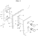
- Fig. 3 illustrates the structure of the impact absorbing portion 10.
- the impact absorbing portion 10 is part of the back surface 2b of the chassis 2 constituting the apparatus main body 1a.
- the impact absorbing portion 10 may be separate from the apparatus main body 1a and may be fixed to the chassis 2 by screwing or the like.
- An impact acting direction Y is assumed to be downward in Figs. 1 and 2 .
- the in-vehicle apparatus 1 according to the embodiment illustrated in Figs. 1 and 2 is configured, if an impact force F greater than a predetermined value is applied between the impact absorbing portion 10 and the support member 20 in a downward impact acting direction Y, to absorb and reduce the impact force F.
- the impact acting direction Y assumed is not limited to the downward direction and may be any direction depending on the placement position of the in-vehicle apparatus 1 in the vehicle component or the kind of the in-vehicle apparatus 1.
- the relative position and the orientation of the impact absorbing portion 10 and the support member 20 are set according to the assumed impact acting direction Y.
- the impact absorbing portion 10 has an opening 11.
- the opening 11 is a long hole whose length extends in the impact acting direction Y.
- a pair of recesses 12 are provided in an inner surface 10a of the impact absorbing portion 10 facing inward of the chassis 2.
- the recesses 12a are formed at a predetermined depth from the inner surface 10a.
- the pair of recesses 12 are positioned above and below the opening 11, with a space therebetween in the impact acting direction Y.
- Each recess 12 is small in width W1 in the impact acting direction Y and is sufficiently larger in width W2 in the X-direction perpendicular to the impact acting direction Y than the width W1.
- the chassis 2 has therein an opposing fixing member 15 that is in contact with the inner surface 10a of the impact absorbing portion 10 and that opposes the support member 20, with the impact absorbing portion 10 therebetween.
- the opposing fixing member 15 has a pair of internal thread holes.
- the internal thread holes 16 are disposed, with a certain distance therebetween in the impact acting direction Y.
- the opposing fixing member 15 has a pair of protrusions 17 protruding integrally from an opposing surface 15a opposing the impact absorbing portion 10.
- the upper protrusion 17 is provided above the upper internal thread hole 16, and the lower protrusion 17 is provided below the lower internal thread hole 16.
- the pair of protrusions 17 are spaced apart from each other in the impact acting direction Y.
- Each protrusion 17 is small in thickness T in the impact acting direction Y and is sufficiently larger in length L in the X-direction perpendicular to the impact acting direction Y than the thickness T.
- the thickness T and the length L of the protrusions 17 are respectively substantially equal to the width W1 and the width W2 of the recesses 12. As illustrated in Fig. 4A , when the protrusions 17 are fitted in the recesses 12 into the fitted state, the opposing fixing member 15 and the impact absorbing portion 10 are positioned without relatively moving in the impact acting direction Y and the X-direction perpendicular to the impact acting direction Y.
- the opposing fixing member 15 is made of an alloy, such as an aluminum alloy or a zinc alloy.
- the impact absorbing portion 10 and the support member 20 are made of iron or an allow. It is assumed that protrusions with the same size as the protrusions 17 are formed on the opposing fixing member 15, the impact absorbing portion 10, or the support member 20.
- the materials of the opposing fixing member 15, the impact absorbing portion 10, and the support member 20 may be selected so that the break strength against a shearing force in the direction of the thickness T of each protrusion is preferably smaller in the opposing fixing member 15 than in the impact absorbing portion 10 and the support member 20. In other words, it is preferable that the break strength of the opposing fixing member 15 per unit cross-sectional area against the shearing force is smaller than the break strength of the impact absorbing portion 10 and the support member 20.
- the support member 20 has a pair of fixing holes 21 spaced in the impact acting direction Y.
- Fastening members 22 are inserted in the corresponding fixing holes 21.
- the fastening members 22 are fixing screws or fixing bolts.
- a washer 23 is disposed between the head of the fastening member 22 and the support member 20 but is not illustrated in Fig. 3 .
- the fastening member 22 may be constituted by a fixing bolt and a nut or may be a press-fit pin or a lock pin to be fitted in the opposing fixing member 15.
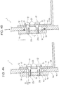
- Fig. 4A illustrates a cross-section structure in which the impact absorbing portion 10, the support member 20, and the opposing fixing member 15 are combined.
- the opposing fixing member 15 is disposed on the inner surface 10a of the impact absorbing portion 10, and the protrusions 17 are fitted in the corresponding recesses 12.
- the fastening members 22 are inserted in the fixing holes 21, with the back surface 2b of the chassis 2 in contact with the support member 20, pass through the opening 11 of the impact absorbing portion 10, and the external threads 22a of the fastening members 22 are screwed in the internal thread holes 16 of the opposing fixing member 15.
- the protrusions 17 and the recesses 12 are fitted, so that the opposing fixing member 15 is positioned and fixed to the impact absorbing portion 10 in the impact acting direction Y and the X-direction perpendicular to the impact acting direction Y. Since the opposing fixing member 15 and the support member 20 are fixed to each other with the fastening members 22, the impact absorbing portion 10, which is part of the apparatus main body 1a, and the support member 20 are also positioned and fixed in the impact acting direction Y and the X-direction. A moving clearance ⁇ is provided in the impact acting direction Y between the opening 11 and the fastening member 22, with the impact absorbing portion 10, the support member 20, and the opposing fixing member 15 combined.
- the chassis 2 and the support member 20 are positioned and fixed by the fitting of the protrusions 17 and the recesses 12. This ensures prevention of the backlash of the apparatus main body 1a with respect to the support member 20 until a predetermined impact force F acts on the chassis 2.
- the impact force F applied when the chassis 2 moves in the impact acting direction Y to the support member 20 to absorb the impact force F, as illustrated in Fig. 4B mainly depends on the material of the opposing fixing member 15 and the size (the cross-sectional area) of the protrusions 17. This facilitates appropriately setting the magnitude of the impact force F, that is, impact load resistance, in designing when an impact absorbing operation as illustrated in Fig. 4B is performed.
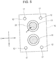
- Fig. 5 is a back view of an in-vehicle apparatus 1 according to a modification of the present disclosure.
- components having the same functions as those of the embodiment illustrated in Figs. 1 to 4B are denoted by the same reference signs.
- the fastening members 22 are illustrated in cross-sectional view, and the support member 20 is omitted.
- the moving clearance ⁇ is set between each of openings 11 formed in the impact absorbing portion 10 and each fastening member 22 in all directions in a plane (a X-Y plane) perpendicular to the axis of the fastening member 22.
- Protrusions 17 formed on the opposing fixing member 15 and recesses 12 formed in the impact absorbing portion 10 are true circles, so that the shearing strength of the protrusions 17 against the shearing force along the X-Y plane is the same in all directions in the X-Y plane.
- Figs. 6 to 8 illustrate the major parts of in-vehicle apparatuses 1 of modifications.
- protrusions 117 protrude from the inner surface 10a of the impact absorbing portion 10, and recesses 112 are formed in the opposing surface 15a of the opposing fixing member 15.
- the protrusions 117 and the recesses 112 are fitted to each other.
- protrusions 217 integrally protrude from the support member 20, and recesses 212 are formed in the impact absorbing portion 10.
- the protrusions 217 and the recesses 212 are fitted to each other.
- protrusions 317 integrally protrude from the impact absorbing portion 10, and recesses 312 are formed in the support member 20.
- the protrusions 317 and the recesses 312 are fitted to each other.
Landscapes
- Engineering & Computer Science (AREA)
- Mechanical Engineering (AREA)
- General Engineering & Computer Science (AREA)
- Vibration Dampers (AREA)
- Fittings On The Vehicle Exterior For Carrying Loads, And Devices For Holding Or Mounting Articles (AREA)
Claims (5)
- Vorrichtung (1), die zur Montage in einem Fahrzeug ausgebildet ist, aufweisend:einen stoßabsorbierenden Bereich (10), der Teil eines Vorrichtungshauptkörpers (1a) ist; undein Abstützelement (20), an dem der stoßabsorbierende Bereich (10) festgelegt ist,wobei die Vorrichtung (1) aufweist:ein gegenüberliegendes Festlegeelement (15), ein Befestigungselement (22), das das Abstützelement (20) und das gegenüberliegende Festlegeelement (15) aneinander befestigt, und eine Öffnung (11) in dem stoßabsorbierenden Bereich (10), in die das Befestigungselement (22) eingesetzt ist;dadurch gekennzeichnet,dass das Abstützelement (20) und das gegenüberliegende Festlegeelement (15) durch das Befestigungselement (22) aneinander befestigt sind, wobei der stoßabsorbierende Bereich (10) zwischen dem Abstützelement (20) und dem gegenüberliegenden Festlegeelement (15) angeordnet ist;dass ein Bewegungsfreiraum (δ) in einer Aufprallwirkungsrichtung zwischen der Öffnung (11) und dem Befestigungselement (22) vorgesehen ist;dass ein Vorsprung (17, 117, 217, 317) an dem einen von dem gegenüberliegenden Festlegeelement (15) und dem stoßabsorbierenden Bereich (10) vorgesehen ist und eine Vertiefung (12, 112, 212, 312) in dem anderen von dem gegenüberliegenden Festlegeelement (15) und dem stoßabsorbierenden Bereich (10) vorgesehen ist, oder ein Vorsprung (17, 117, 217, 317) an dem einen von dem Abstützelement (20) und dem stoßabsorbierenden Bereich (10) vorgesehen ist und eine Vertiefung (12, 112, 212, 312) in dem anderen von dem Abstützelement (20) und dem stoßabsorbierenden Bereich (10) vorgesehen ist;dass der Vorsprung (17, 117, 217, 317) und die Vertiefung (12, 112, 212, 312) derart ausgebildet sind, dass sie zur Positionierung des stoßabsorbierenden Bereichs (10) und des Abstützelements (20) in der Aufprallwirkungsrichtung passend ausgebildet sind; unddass der Vorsprung (17, 117, 217, 317) dazu ausgebildet ist, separiert zu werden, wenn eine Scherkraft in der Aufprallwirkungsrichtung auf den Vorsprung (17, 117, 217, 317) wirkt.
- Vorrichtung (1) nach Anspruch 1,
dadurch gekennzeichnet,
dass der Vorsprung (17) an dem gegenüberliegenden Festlegeelement (15) vorgesehen ist; und
dass eine Scherfestigkeit pro Querschnittsflächeneinheit gegenüber einer Scherkraft in dem gegenüberliegenden Festlegeelement (15) geringer ist als in dem stoßabsorbierenden Bereich (10) und dem Abstützelement (20). - Vorrichtung (1) nach Anspruch 1 oder 2,
dadurch gekennzeichnet,
dass der Vorsprung (17) in der Aufprallwirkungsrichtung eine geringere Breite (W1) als eine Länge (W2) in einer Richtung rechtwinklig zu der Aufprallwirkungsrichtung aufweist; und
dass der Vorsprung (17) dazu ausgebildet ist, durch eine in die Breite (W1) gerichtete Scherkraft separiert zu werden. - Vorrichtung (1) nach einem der Ansprüche 1 bis 3,
dadurch gekennzeichnet,
dass der Bewegungsfreiraum (δ) zwischen der Öffnung (11) und dem Befestigungselement (22) in allen Richtungen in einer Ebene rechtwinklig zu einer Achse des Befestigungselements (22) vorgesehen ist; und
dass der Vorsprung (17) dazu ausgebildet ist, durch eine Scherkraft in einer beliebigen Richtung in der Ebene separiert zu werden. - Fahrzeug, das die Vorrichtung nach einem der vorhergehenden Ansprüche aufweist.
Applications Claiming Priority (1)
| Application Number | Priority Date | Filing Date | Title |
|---|---|---|---|
| JP2018090364A JP6987461B2 (ja) | 2018-05-09 | 2018-05-09 | 車載用装置 |
Publications (2)
| Publication Number | Publication Date |
|---|---|
| EP3567265A1 EP3567265A1 (de) | 2019-11-13 |
| EP3567265B1 true EP3567265B1 (de) | 2020-06-03 |
Family
ID=66397140
Family Applications (1)
| Application Number | Title | Priority Date | Filing Date |
|---|---|---|---|
| EP19172555.5A Active EP3567265B1 (de) | 2018-05-09 | 2019-05-03 | Vorrichtung zur befestigung in einem kraftfahrzeug |
Country Status (2)
| Country | Link |
|---|---|
| EP (1) | EP3567265B1 (de) |
| JP (1) | JP6987461B2 (de) |
Families Citing this family (1)
| Publication number | Priority date | Publication date | Assignee | Title |
|---|---|---|---|---|
| JP7100072B2 (ja) * | 2020-01-08 | 2022-07-12 | 本田技研工業株式会社 | センサ取付ブラケット |
Family Cites Families (11)
| Publication number | Priority date | Publication date | Assignee | Title |
|---|---|---|---|---|
| JPH0518016A (ja) * | 1991-02-28 | 1993-01-26 | Teraoka Enterp Kk | 鉄骨構造物の連結用当て板 |
| JPH0948292A (ja) * | 1995-08-08 | 1997-02-18 | Mitsubishi Motors Corp | 車載用機器の取付構造 |
| KR20000048303A (ko) * | 1998-12-26 | 2000-07-25 | 정훈광 | 전단링을 이용한 강재의 접합구조 및 그 강재의 접합공법 |
| JP2001347895A (ja) * | 2000-06-08 | 2001-12-18 | Nissan Shatai Co Ltd | モニタ取付構造 |
| JP2002050880A (ja) * | 2000-07-31 | 2002-02-15 | Fujitsu Ten Ltd | 衝撃吸収構造 |
| JP2006066288A (ja) * | 2004-08-27 | 2006-03-09 | Mitsubishi Electric Corp | 操作機構 |
| US20070001083A1 (en) * | 2005-06-30 | 2007-01-04 | Daniel Martin | Mounting apparatus for a mobile communication device |
| JP2008221867A (ja) * | 2007-03-08 | 2008-09-25 | Mazda Motor Corp | 車両の電子ユニットカバー構造 |
| JP2013198330A (ja) * | 2012-03-21 | 2013-09-30 | Keihin Corp | 車両における機器ボックスの支持構造 |
| US9487157B1 (en) * | 2015-07-10 | 2016-11-08 | Ford Global Technologies, Llc | Vehicle display assembly including an energy absorption element |
| JP2017050037A (ja) * | 2015-09-03 | 2017-03-09 | ソニー株式会社 | 電子機器 |
-
2018
- 2018-05-09 JP JP2018090364A patent/JP6987461B2/ja active Active
-
2019
- 2019-05-03 EP EP19172555.5A patent/EP3567265B1/de active Active
Non-Patent Citations (1)
| Title |
|---|
| None * |
Also Published As
| Publication number | Publication date |
|---|---|
| EP3567265A1 (de) | 2019-11-13 |
| JP6987461B2 (ja) | 2022-01-05 |
| JP2019196066A (ja) | 2019-11-14 |
Similar Documents
| Publication | Publication Date | Title |
|---|---|---|
| CN107031402B (zh) | 车辆的显示屏设备和信息装置以及制造信息装置的方法 | |
| EP1511368B1 (de) | Sandwich Gehäuse für einen Antennenverstärker | |
| KR101376870B1 (ko) | 기기 지지 스탠드 | |
| DE60220574T2 (de) | Schaltanordnung für ein Kraftfahrzeug mit stoßabsorbierender Vorrichtung | |
| US7997548B2 (en) | Vehicle shifter mounting bracket system and method | |
| US10426048B2 (en) | Electronic device accommodating housing and method of attaching the same | |
| WO2010091819A1 (de) | Befestigungsanordnung für ein airbagmodulgehäuse | |
| EP3567265A1 (de) | Vorrichtung mit konfiguration zur installation in einem fahrzeug | |
| JP2013198330A (ja) | 車両における機器ボックスの支持構造 | |
| US7654864B2 (en) | Mounting bracket structure | |
| US20220073125A1 (en) | Steering Column Impact Energy Absorber, with Loop Closed by a Breakaway Link | |
| DE102007036959B4 (de) | Bodenplatte für eine Sensorbaugruppe, Trägerkörper zur Befestigung der Bodenplatte, Sensorbaugruppe und Befestigungssystem | |
| JP2012208821A (ja) | つまみ装置 | |
| JP7201374B2 (ja) | ブラケットおよび電子機器 | |
| DE102005053326B3 (de) | Anordnung mit einer an einem Kraftfahrzeugteil befestigten Beschleunigungssensorvorrichtung | |
| KR100902742B1 (ko) | 프론트 엔드 모듈의 헤드램프 장착구조 | |
| US20200114870A1 (en) | Apparatus for preventing forcible separation of shift cable | |
| DE102007038737B4 (de) | Bodenplatte für eine Sensorbaugruppe, Trägerkörper zur Befestigung der Sensorbaugruppe, Sensorbaugruppe und Befestigungssystem | |
| US7441808B2 (en) | Steering column assembly comprising a steering column the tilt and length of which can be modified | |
| JP4394312B2 (ja) | 車載用表示装置 | |
| KR20230042932A (ko) | 차량의 장착물 마운팅 구조 | |
| US10315684B2 (en) | Steering column for a motor vehicle | |
| DE102023136730B3 (de) | Eingabegerät mit verbesserter Festlegung eines zugehörigen Aktuators zur Erzeugung eines haptischen Feedbacks, zugehörige Verwendung und Montageverfahren | |
| JP2005014832A (ja) | 衝撃吸収ステアリング装置の取付構造 | |
| EP4074988B1 (de) | Verbindungssystem und verfahren zum verbinden |
Legal Events
| Date | Code | Title | Description |
|---|---|---|---|
| PUAI | Public reference made under article 153(3) epc to a published international application that has entered the european phase |
Free format text: ORIGINAL CODE: 0009012 |
|
| STAA | Information on the status of an ep patent application or granted ep patent |
Free format text: STATUS: THE APPLICATION HAS BEEN PUBLISHED |
|
| AK | Designated contracting states |
Kind code of ref document: A1 Designated state(s): AL AT BE BG CH CY CZ DE DK EE ES FI FR GB GR HR HU IE IS IT LI LT LU LV MC MK MT NL NO PL PT RO RS SE SI SK SM TR |
|
| AX | Request for extension of the european patent |
Extension state: BA ME |
|
| STAA | Information on the status of an ep patent application or granted ep patent |
Free format text: STATUS: REQUEST FOR EXAMINATION WAS MADE |
|
| GRAP | Despatch of communication of intention to grant a patent |
Free format text: ORIGINAL CODE: EPIDOSNIGR1 |
|
| STAA | Information on the status of an ep patent application or granted ep patent |
Free format text: STATUS: GRANT OF PATENT IS INTENDED |
|
| 17P | Request for examination filed |
Effective date: 20191113 |
|
| RBV | Designated contracting states (corrected) |
Designated state(s): AL AT BE BG CH CY CZ DE DK EE ES FI FR GB GR HR HU IE IS IT LI LT LU LV MC MK MT NL NO PL PT RO RS SE SI SK SM TR |
|
| INTG | Intention to grant announced |
Effective date: 20191218 |
|
| RAP1 | Party data changed (applicant data changed or rights of an application transferred) |
Owner name: ALPINE ELECTRONICS, INC. |
|
| GRAS | Grant fee paid |
Free format text: ORIGINAL CODE: EPIDOSNIGR3 |
|
| GRAA | (expected) grant |
Free format text: ORIGINAL CODE: 0009210 |
|
| STAA | Information on the status of an ep patent application or granted ep patent |
Free format text: STATUS: THE PATENT HAS BEEN GRANTED |
|
| AK | Designated contracting states |
Kind code of ref document: B1 Designated state(s): AL AT BE BG CH CY CZ DE DK EE ES FI FR GB GR HR HU IE IS IT LI LT LU LV MC MK MT NL NO PL PT RO RS SE SI SK SM TR |
|
| REG | Reference to a national code |
Ref country code: GB Ref legal event code: FG4D |
|
| REG | Reference to a national code |
Ref country code: CH Ref legal event code: EP Ref country code: AT Ref legal event code: REF Ref document number: 1277299 Country of ref document: AT Kind code of ref document: T Effective date: 20200615 |
|
| REG | Reference to a national code |
Ref country code: DE Ref legal event code: R096 Ref document number: 602019000164 Country of ref document: DE |
|
| REG | Reference to a national code |
Ref country code: LT Ref legal event code: MG4D |
|
| PG25 | Lapsed in a contracting state [announced via postgrant information from national office to epo] |
Ref country code: FI Free format text: LAPSE BECAUSE OF FAILURE TO SUBMIT A TRANSLATION OF THE DESCRIPTION OR TO PAY THE FEE WITHIN THE PRESCRIBED TIME-LIMIT Effective date: 20200603 Ref country code: NO Free format text: LAPSE BECAUSE OF FAILURE TO SUBMIT A TRANSLATION OF THE DESCRIPTION OR TO PAY THE FEE WITHIN THE PRESCRIBED TIME-LIMIT Effective date: 20200903 Ref country code: SE Free format text: LAPSE BECAUSE OF FAILURE TO SUBMIT A TRANSLATION OF THE DESCRIPTION OR TO PAY THE FEE WITHIN THE PRESCRIBED TIME-LIMIT Effective date: 20200603 Ref country code: LT Free format text: LAPSE BECAUSE OF FAILURE TO SUBMIT A TRANSLATION OF THE DESCRIPTION OR TO PAY THE FEE WITHIN THE PRESCRIBED TIME-LIMIT Effective date: 20200603 Ref country code: GR Free format text: LAPSE BECAUSE OF FAILURE TO SUBMIT A TRANSLATION OF THE DESCRIPTION OR TO PAY THE FEE WITHIN THE PRESCRIBED TIME-LIMIT Effective date: 20200904 |
|
| REG | Reference to a national code |
Ref country code: NL Ref legal event code: MP Effective date: 20200603 |
|
| PG25 | Lapsed in a contracting state [announced via postgrant information from national office to epo] |
Ref country code: BG Free format text: LAPSE BECAUSE OF FAILURE TO SUBMIT A TRANSLATION OF THE DESCRIPTION OR TO PAY THE FEE WITHIN THE PRESCRIBED TIME-LIMIT Effective date: 20200903 Ref country code: RS Free format text: LAPSE BECAUSE OF FAILURE TO SUBMIT A TRANSLATION OF THE DESCRIPTION OR TO PAY THE FEE WITHIN THE PRESCRIBED TIME-LIMIT Effective date: 20200603 Ref country code: LV Free format text: LAPSE BECAUSE OF FAILURE TO SUBMIT A TRANSLATION OF THE DESCRIPTION OR TO PAY THE FEE WITHIN THE PRESCRIBED TIME-LIMIT Effective date: 20200603 Ref country code: HR Free format text: LAPSE BECAUSE OF FAILURE TO SUBMIT A TRANSLATION OF THE DESCRIPTION OR TO PAY THE FEE WITHIN THE PRESCRIBED TIME-LIMIT Effective date: 20200603 |
|
| REG | Reference to a national code |
Ref country code: AT Ref legal event code: MK05 Ref document number: 1277299 Country of ref document: AT Kind code of ref document: T Effective date: 20200603 |
|
| PG25 | Lapsed in a contracting state [announced via postgrant information from national office to epo] |
Ref country code: NL Free format text: LAPSE BECAUSE OF FAILURE TO SUBMIT A TRANSLATION OF THE DESCRIPTION OR TO PAY THE FEE WITHIN THE PRESCRIBED TIME-LIMIT Effective date: 20200603 Ref country code: AL Free format text: LAPSE BECAUSE OF FAILURE TO SUBMIT A TRANSLATION OF THE DESCRIPTION OR TO PAY THE FEE WITHIN THE PRESCRIBED TIME-LIMIT Effective date: 20200603 |
|
| PG25 | Lapsed in a contracting state [announced via postgrant information from national office to epo] |
Ref country code: ES Free format text: LAPSE BECAUSE OF FAILURE TO SUBMIT A TRANSLATION OF THE DESCRIPTION OR TO PAY THE FEE WITHIN THE PRESCRIBED TIME-LIMIT Effective date: 20200603 Ref country code: SM Free format text: LAPSE BECAUSE OF FAILURE TO SUBMIT A TRANSLATION OF THE DESCRIPTION OR TO PAY THE FEE WITHIN THE PRESCRIBED TIME-LIMIT Effective date: 20200603 Ref country code: AT Free format text: LAPSE BECAUSE OF FAILURE TO SUBMIT A TRANSLATION OF THE DESCRIPTION OR TO PAY THE FEE WITHIN THE PRESCRIBED TIME-LIMIT Effective date: 20200603 Ref country code: EE Free format text: LAPSE BECAUSE OF FAILURE TO SUBMIT A TRANSLATION OF THE DESCRIPTION OR TO PAY THE FEE WITHIN THE PRESCRIBED TIME-LIMIT Effective date: 20200603 Ref country code: PT Free format text: LAPSE BECAUSE OF FAILURE TO SUBMIT A TRANSLATION OF THE DESCRIPTION OR TO PAY THE FEE WITHIN THE PRESCRIBED TIME-LIMIT Effective date: 20201006 Ref country code: IT Free format text: LAPSE BECAUSE OF FAILURE TO SUBMIT A TRANSLATION OF THE DESCRIPTION OR TO PAY THE FEE WITHIN THE PRESCRIBED TIME-LIMIT Effective date: 20200603 Ref country code: RO Free format text: LAPSE BECAUSE OF FAILURE TO SUBMIT A TRANSLATION OF THE DESCRIPTION OR TO PAY THE FEE WITHIN THE PRESCRIBED TIME-LIMIT Effective date: 20200603 Ref country code: CZ Free format text: LAPSE BECAUSE OF FAILURE TO SUBMIT A TRANSLATION OF THE DESCRIPTION OR TO PAY THE FEE WITHIN THE PRESCRIBED TIME-LIMIT Effective date: 20200603 |
|
| PG25 | Lapsed in a contracting state [announced via postgrant information from national office to epo] |
Ref country code: PL Free format text: LAPSE BECAUSE OF FAILURE TO SUBMIT A TRANSLATION OF THE DESCRIPTION OR TO PAY THE FEE WITHIN THE PRESCRIBED TIME-LIMIT Effective date: 20200603 Ref country code: SK Free format text: LAPSE BECAUSE OF FAILURE TO SUBMIT A TRANSLATION OF THE DESCRIPTION OR TO PAY THE FEE WITHIN THE PRESCRIBED TIME-LIMIT Effective date: 20200603 Ref country code: IS Free format text: LAPSE BECAUSE OF FAILURE TO SUBMIT A TRANSLATION OF THE DESCRIPTION OR TO PAY THE FEE WITHIN THE PRESCRIBED TIME-LIMIT Effective date: 20201003 |
|
| REG | Reference to a national code |
Ref country code: DE Ref legal event code: R097 Ref document number: 602019000164 Country of ref document: DE |
|
| PLBE | No opposition filed within time limit |
Free format text: ORIGINAL CODE: 0009261 |
|
| STAA | Information on the status of an ep patent application or granted ep patent |
Free format text: STATUS: NO OPPOSITION FILED WITHIN TIME LIMIT |
|
| PG25 | Lapsed in a contracting state [announced via postgrant information from national office to epo] |
Ref country code: DK Free format text: LAPSE BECAUSE OF FAILURE TO SUBMIT A TRANSLATION OF THE DESCRIPTION OR TO PAY THE FEE WITHIN THE PRESCRIBED TIME-LIMIT Effective date: 20200603 |
|
| 26N | No opposition filed |
Effective date: 20210304 |
|
| PG25 | Lapsed in a contracting state [announced via postgrant information from national office to epo] |
Ref country code: MC Free format text: LAPSE BECAUSE OF FAILURE TO SUBMIT A TRANSLATION OF THE DESCRIPTION OR TO PAY THE FEE WITHIN THE PRESCRIBED TIME-LIMIT Effective date: 20200603 Ref country code: LU Free format text: LAPSE BECAUSE OF NON-PAYMENT OF DUE FEES Effective date: 20210503 |
|
| REG | Reference to a national code |
Ref country code: BE Ref legal event code: MM Effective date: 20210531 |
|
| PG25 | Lapsed in a contracting state [announced via postgrant information from national office to epo] |
Ref country code: IE Free format text: LAPSE BECAUSE OF NON-PAYMENT OF DUE FEES Effective date: 20210503 |
|
| PG25 | Lapsed in a contracting state [announced via postgrant information from national office to epo] |
Ref country code: BE Free format text: LAPSE BECAUSE OF NON-PAYMENT OF DUE FEES Effective date: 20210531 |
|
| REG | Reference to a national code |
Ref country code: CH Ref legal event code: PL |
|
| PG25 | Lapsed in a contracting state [announced via postgrant information from national office to epo] |
Ref country code: LI Free format text: LAPSE BECAUSE OF NON-PAYMENT OF DUE FEES Effective date: 20220531 Ref country code: CH Free format text: LAPSE BECAUSE OF NON-PAYMENT OF DUE FEES Effective date: 20220531 |
|
| PG25 | Lapsed in a contracting state [announced via postgrant information from national office to epo] |
Ref country code: CY Free format text: LAPSE BECAUSE OF FAILURE TO SUBMIT A TRANSLATION OF THE DESCRIPTION OR TO PAY THE FEE WITHIN THE PRESCRIBED TIME-LIMIT Effective date: 20200603 |
|
| PG25 | Lapsed in a contracting state [announced via postgrant information from national office to epo] |
Ref country code: HU Free format text: LAPSE BECAUSE OF FAILURE TO SUBMIT A TRANSLATION OF THE DESCRIPTION OR TO PAY THE FEE WITHIN THE PRESCRIBED TIME-LIMIT; INVALID AB INITIO Effective date: 20190503 |
|
| PG25 | Lapsed in a contracting state [announced via postgrant information from national office to epo] |
Ref country code: SI Free format text: LAPSE BECAUSE OF FAILURE TO SUBMIT A TRANSLATION OF THE DESCRIPTION OR TO PAY THE FEE WITHIN THE PRESCRIBED TIME-LIMIT Effective date: 20200603 |
|
| PG25 | Lapsed in a contracting state [announced via postgrant information from national office to epo] |
Ref country code: MK Free format text: LAPSE BECAUSE OF FAILURE TO SUBMIT A TRANSLATION OF THE DESCRIPTION OR TO PAY THE FEE WITHIN THE PRESCRIBED TIME-LIMIT Effective date: 20200603 |
|
| PG25 | Lapsed in a contracting state [announced via postgrant information from national office to epo] |
Ref country code: TR Free format text: LAPSE BECAUSE OF FAILURE TO SUBMIT A TRANSLATION OF THE DESCRIPTION OR TO PAY THE FEE WITHIN THE PRESCRIBED TIME-LIMIT Effective date: 20200603 |
|
| PG25 | Lapsed in a contracting state [announced via postgrant information from national office to epo] |
Ref country code: MT Free format text: LAPSE BECAUSE OF FAILURE TO SUBMIT A TRANSLATION OF THE DESCRIPTION OR TO PAY THE FEE WITHIN THE PRESCRIBED TIME-LIMIT Effective date: 20200603 |
|
| PGFP | Annual fee paid to national office [announced via postgrant information from national office to epo] |
Ref country code: DE Payment date: 20250521 Year of fee payment: 7 |
|
| PGFP | Annual fee paid to national office [announced via postgrant information from national office to epo] |
Ref country code: GB Payment date: 20250527 Year of fee payment: 7 |
|
| PGFP | Annual fee paid to national office [announced via postgrant information from national office to epo] |
Ref country code: FR Payment date: 20250528 Year of fee payment: 7 |