EP3565741B1 - Wärmesteuerungssystem für ein digitales kennzeichenschild - Google Patents
Wärmesteuerungssystem für ein digitales kennzeichenschild Download PDFInfo
- Publication number
- EP3565741B1 EP3565741B1 EP18735795.9A EP18735795A EP3565741B1 EP 3565741 B1 EP3565741 B1 EP 3565741B1 EP 18735795 A EP18735795 A EP 18735795A EP 3565741 B1 EP3565741 B1 EP 3565741B1
- Authority
- EP
- European Patent Office
- Prior art keywords
- display
- vehicle
- license plate
- digital license
- temperature
- Prior art date
- Legal status (The legal status is an assumption and is not a legal conclusion. Google has not performed a legal analysis and makes no representation as to the accuracy of the status listed.)
- Active
Links
- 238000000034 method Methods 0.000 claims description 56
- 230000007423 decrease Effects 0.000 claims description 10
- 230000003247 decreasing effect Effects 0.000 claims description 9
- 238000002310 reflectometry Methods 0.000 claims description 8
- 238000010521 absorption reaction Methods 0.000 claims description 7
- 238000010438 heat treatment Methods 0.000 claims description 7
- 239000003981 vehicle Substances 0.000 description 204
- 238000004891 communication Methods 0.000 description 38
- 230000006870 function Effects 0.000 description 23
- 238000003860 storage Methods 0.000 description 14
- 238000010586 diagram Methods 0.000 description 13
- 239000000463 material Substances 0.000 description 9
- 239000002245 particle Substances 0.000 description 8
- 239000000049 pigment Substances 0.000 description 8
- 238000001816 cooling Methods 0.000 description 7
- 230000004044 response Effects 0.000 description 7
- 230000000694 effects Effects 0.000 description 6
- 230000009471 action Effects 0.000 description 5
- 238000004590 computer program Methods 0.000 description 5
- 238000007726 management method Methods 0.000 description 5
- 230000002829 reductive effect Effects 0.000 description 5
- 238000013478 data encryption standard Methods 0.000 description 4
- 238000012545 processing Methods 0.000 description 4
- 230000011664 signaling Effects 0.000 description 4
- 230000001133 acceleration Effects 0.000 description 3
- 238000000576 coating method Methods 0.000 description 3
- 238000012423 maintenance Methods 0.000 description 3
- 239000004005 microsphere Substances 0.000 description 3
- 230000001681 protective effect Effects 0.000 description 3
- 238000009877 rendering Methods 0.000 description 3
- 230000007704 transition Effects 0.000 description 3
- 239000012463 white pigment Substances 0.000 description 3
- GWEVSGVZZGPLCZ-UHFFFAOYSA-N Titan oxide Chemical compound O=[Ti]=O GWEVSGVZZGPLCZ-UHFFFAOYSA-N 0.000 description 2
- 230000001413 cellular effect Effects 0.000 description 2
- 238000001652 electrophoretic deposition Methods 0.000 description 2
- 230000002209 hydrophobic effect Effects 0.000 description 2
- 230000008520 organization Effects 0.000 description 2
- 238000013021 overheating Methods 0.000 description 2
- 238000005070 sampling Methods 0.000 description 2
- 230000003068 static effect Effects 0.000 description 2
- 238000012360 testing method Methods 0.000 description 2
- 238000012546 transfer Methods 0.000 description 2
- 230000000007 visual effect Effects 0.000 description 2
- 239000004986 Cholesteric liquid crystals (ChLC) Substances 0.000 description 1
- 241001465754 Metazoa Species 0.000 description 1
- 206010028980 Neoplasm Diseases 0.000 description 1
- 229920005372 Plexiglas® Polymers 0.000 description 1
- 239000011358 absorbing material Substances 0.000 description 1
- 230000004913 activation Effects 0.000 description 1
- 230000004075 alteration Effects 0.000 description 1
- 230000008901 benefit Effects 0.000 description 1
- 230000033228 biological regulation Effects 0.000 description 1
- 230000005540 biological transmission Effects 0.000 description 1
- 238000009529 body temperature measurement Methods 0.000 description 1
- 201000011510 cancer Diseases 0.000 description 1
- 230000015556 catabolic process Effects 0.000 description 1
- 239000003795 chemical substances by application Substances 0.000 description 1
- 238000004140 cleaning Methods 0.000 description 1
- 239000011248 coating agent Substances 0.000 description 1
- 239000003086 colorant Substances 0.000 description 1
- 150000001875 compounds Chemical class 0.000 description 1
- 239000013078 crystal Substances 0.000 description 1
- 238000007405 data analysis Methods 0.000 description 1
- 238000013500 data storage Methods 0.000 description 1
- 230000009849 deactivation Effects 0.000 description 1
- 238000013461 design Methods 0.000 description 1
- 239000006185 dispersion Substances 0.000 description 1
- 229940079593 drug Drugs 0.000 description 1
- 239000003814 drug Substances 0.000 description 1
- 239000000428 dust Substances 0.000 description 1
- 238000005516 engineering process Methods 0.000 description 1
- 230000001815 facial effect Effects 0.000 description 1
- 230000002349 favourable effect Effects 0.000 description 1
- 238000007710 freezing Methods 0.000 description 1
- 230000008014 freezing Effects 0.000 description 1
- 230000017525 heat dissipation Effects 0.000 description 1
- 230000003993 interaction Effects 0.000 description 1
- 230000000670 limiting effect Effects 0.000 description 1
- 239000007788 liquid Substances 0.000 description 1
- 239000004973 liquid crystal related substance Substances 0.000 description 1
- 238000004519 manufacturing process Methods 0.000 description 1
- 238000005259 measurement Methods 0.000 description 1
- 238000002483 medication Methods 0.000 description 1
- 239000000203 mixture Substances 0.000 description 1
- 238000012986 modification Methods 0.000 description 1
- 230000004048 modification Effects 0.000 description 1
- 230000003287 optical effect Effects 0.000 description 1
- 230000002093 peripheral effect Effects 0.000 description 1
- 230000001699 photocatalysis Effects 0.000 description 1
- 239000004926 polymethyl methacrylate Substances 0.000 description 1
- 238000011176 pooling Methods 0.000 description 1
- 230000001737 promoting effect Effects 0.000 description 1
- 238000007788 roughening Methods 0.000 description 1
- 229910052594 sapphire Inorganic materials 0.000 description 1
- 239000010980 sapphire Substances 0.000 description 1
- 239000005348 self-cleaning glass Substances 0.000 description 1
- 239000002904 solvent Substances 0.000 description 1
- 239000000126 substance Substances 0.000 description 1
- 239000004408 titanium dioxide Substances 0.000 description 1
- 238000009423 ventilation Methods 0.000 description 1
- XLYOFNOQVPJJNP-UHFFFAOYSA-N water Substances O XLYOFNOQVPJJNP-UHFFFAOYSA-N 0.000 description 1
Images


Classifications
-
- B—PERFORMING OPERATIONS; TRANSPORTING
- B60—VEHICLES IN GENERAL
- B60R—VEHICLES, VEHICLE FITTINGS, OR VEHICLE PARTS, NOT OTHERWISE PROVIDED FOR
- B60R13/00—Elements for body-finishing, identifying, or decorating; Arrangements or adaptations for advertising purposes
- B60R13/10—Registration, licensing, or like devices
-
- B—PERFORMING OPERATIONS; TRANSPORTING
- B60—VEHICLES IN GENERAL
- B60Q—ARRANGEMENT OF SIGNALLING OR LIGHTING DEVICES, THE MOUNTING OR SUPPORTING THEREOF OR CIRCUITS THEREFOR, FOR VEHICLES IN GENERAL
- B60Q1/00—Arrangement of optical signalling or lighting devices, the mounting or supporting thereof or circuits therefor
- B60Q1/26—Arrangement of optical signalling or lighting devices, the mounting or supporting thereof or circuits therefor the devices being primarily intended to indicate the vehicle, or parts thereof, or to give signals, to other traffic
- B60Q1/50—Arrangement of optical signalling or lighting devices, the mounting or supporting thereof or circuits therefor the devices being primarily intended to indicate the vehicle, or parts thereof, or to give signals, to other traffic for indicating other intentions or conditions, e.g. request for waiting or overtaking
- B60Q1/503—Arrangement of optical signalling or lighting devices, the mounting or supporting thereof or circuits therefor the devices being primarily intended to indicate the vehicle, or parts thereof, or to give signals, to other traffic for indicating other intentions or conditions, e.g. request for waiting or overtaking using luminous text or symbol displays in or on the vehicle, e.g. static text
- B60Q1/5035—Arrangement of optical signalling or lighting devices, the mounting or supporting thereof or circuits therefor the devices being primarily intended to indicate the vehicle, or parts thereof, or to give signals, to other traffic for indicating other intentions or conditions, e.g. request for waiting or overtaking using luminous text or symbol displays in or on the vehicle, e.g. static text electronic displays
-
- B—PERFORMING OPERATIONS; TRANSPORTING
- B60—VEHICLES IN GENERAL
- B60Q—ARRANGEMENT OF SIGNALLING OR LIGHTING DEVICES, THE MOUNTING OR SUPPORTING THEREOF OR CIRCUITS THEREFOR, FOR VEHICLES IN GENERAL
- B60Q1/00—Arrangement of optical signalling or lighting devices, the mounting or supporting thereof or circuits therefor
- B60Q1/26—Arrangement of optical signalling or lighting devices, the mounting or supporting thereof or circuits therefor the devices being primarily intended to indicate the vehicle, or parts thereof, or to give signals, to other traffic
- B60Q1/50—Arrangement of optical signalling or lighting devices, the mounting or supporting thereof or circuits therefor the devices being primarily intended to indicate the vehicle, or parts thereof, or to give signals, to other traffic for indicating other intentions or conditions, e.g. request for waiting or overtaking
- B60Q1/508—Arrangement of optical signalling or lighting devices, the mounting or supporting thereof or circuits therefor the devices being primarily intended to indicate the vehicle, or parts thereof, or to give signals, to other traffic for indicating other intentions or conditions, e.g. request for waiting or overtaking specific to vehicles driving in fleets or convoys
-
- B—PERFORMING OPERATIONS; TRANSPORTING
- B60—VEHICLES IN GENERAL
- B60Q—ARRANGEMENT OF SIGNALLING OR LIGHTING DEVICES, THE MOUNTING OR SUPPORTING THEREOF OR CIRCUITS THEREFOR, FOR VEHICLES IN GENERAL
- B60Q1/00—Arrangement of optical signalling or lighting devices, the mounting or supporting thereof or circuits therefor
- B60Q1/26—Arrangement of optical signalling or lighting devices, the mounting or supporting thereof or circuits therefor the devices being primarily intended to indicate the vehicle, or parts thereof, or to give signals, to other traffic
- B60Q1/50—Arrangement of optical signalling or lighting devices, the mounting or supporting thereof or circuits therefor the devices being primarily intended to indicate the vehicle, or parts thereof, or to give signals, to other traffic for indicating other intentions or conditions, e.g. request for waiting or overtaking
- B60Q1/509—Arrangement of optical signalling or lighting devices, the mounting or supporting thereof or circuits therefor the devices being primarily intended to indicate the vehicle, or parts thereof, or to give signals, to other traffic for indicating other intentions or conditions, e.g. request for waiting or overtaking specific to unauthorised use, e.g. for indicating stolen vehicles or infringements of traffic rules
-
- B—PERFORMING OPERATIONS; TRANSPORTING
- B60—VEHICLES IN GENERAL
- B60Q—ARRANGEMENT OF SIGNALLING OR LIGHTING DEVICES, THE MOUNTING OR SUPPORTING THEREOF OR CIRCUITS THEREFOR, FOR VEHICLES IN GENERAL
- B60Q1/00—Arrangement of optical signalling or lighting devices, the mounting or supporting thereof or circuits therefor
- B60Q1/26—Arrangement of optical signalling or lighting devices, the mounting or supporting thereof or circuits therefor the devices being primarily intended to indicate the vehicle, or parts thereof, or to give signals, to other traffic
- B60Q1/50—Arrangement of optical signalling or lighting devices, the mounting or supporting thereof or circuits therefor the devices being primarily intended to indicate the vehicle, or parts thereof, or to give signals, to other traffic for indicating other intentions or conditions, e.g. request for waiting or overtaking
- B60Q1/543—Arrangement of optical signalling or lighting devices, the mounting or supporting thereof or circuits therefor the devices being primarily intended to indicate the vehicle, or parts thereof, or to give signals, to other traffic for indicating other intentions or conditions, e.g. request for waiting or overtaking for indicating other states or conditions of the vehicle
-
- B—PERFORMING OPERATIONS; TRANSPORTING
- B60—VEHICLES IN GENERAL
- B60Q—ARRANGEMENT OF SIGNALLING OR LIGHTING DEVICES, THE MOUNTING OR SUPPORTING THEREOF OR CIRCUITS THEREFOR, FOR VEHICLES IN GENERAL
- B60Q1/00—Arrangement of optical signalling or lighting devices, the mounting or supporting thereof or circuits therefor
- B60Q1/26—Arrangement of optical signalling or lighting devices, the mounting or supporting thereof or circuits therefor the devices being primarily intended to indicate the vehicle, or parts thereof, or to give signals, to other traffic
- B60Q1/50—Arrangement of optical signalling or lighting devices, the mounting or supporting thereof or circuits therefor the devices being primarily intended to indicate the vehicle, or parts thereof, or to give signals, to other traffic for indicating other intentions or conditions, e.g. request for waiting or overtaking
- B60Q1/545—Arrangement of optical signalling or lighting devices, the mounting or supporting thereof or circuits therefor the devices being primarily intended to indicate the vehicle, or parts thereof, or to give signals, to other traffic for indicating other intentions or conditions, e.g. request for waiting or overtaking for indicating other traffic conditions, e.g. fog, heavy traffic
-
- B—PERFORMING OPERATIONS; TRANSPORTING
- B60—VEHICLES IN GENERAL
- B60Q—ARRANGEMENT OF SIGNALLING OR LIGHTING DEVICES, THE MOUNTING OR SUPPORTING THEREOF OR CIRCUITS THEREFOR, FOR VEHICLES IN GENERAL
- B60Q1/00—Arrangement of optical signalling or lighting devices, the mounting or supporting thereof or circuits therefor
- B60Q1/26—Arrangement of optical signalling or lighting devices, the mounting or supporting thereof or circuits therefor the devices being primarily intended to indicate the vehicle, or parts thereof, or to give signals, to other traffic
- B60Q1/56—Arrangement of optical signalling or lighting devices, the mounting or supporting thereof or circuits therefor the devices being primarily intended to indicate the vehicle, or parts thereof, or to give signals, to other traffic for illuminating registrations or the like, e.g. for licence plates
-
- G—PHYSICS
- G05—CONTROLLING; REGULATING
- G05B—CONTROL OR REGULATING SYSTEMS IN GENERAL; FUNCTIONAL ELEMENTS OF SUCH SYSTEMS; MONITORING OR TESTING ARRANGEMENTS FOR SUCH SYSTEMS OR ELEMENTS
- G05B15/00—Systems controlled by a computer
- G05B15/02—Systems controlled by a computer electric
-
- G—PHYSICS
- G05—CONTROLLING; REGULATING
- G05D—SYSTEMS FOR CONTROLLING OR REGULATING NON-ELECTRIC VARIABLES
- G05D23/00—Control of temperature
- G05D23/19—Control of temperature characterised by the use of electric means
- G05D23/1917—Control of temperature characterised by the use of electric means using digital means
-
- G—PHYSICS
- G09—EDUCATION; CRYPTOGRAPHY; DISPLAY; ADVERTISING; SEALS
- G09F—DISPLAYING; ADVERTISING; SIGNS; LABELS OR NAME-PLATES; SEALS
- G09F21/00—Mobile visual advertising
- G09F21/04—Mobile visual advertising by land vehicles
- G09F21/048—Advertisement panels on sides, front or back of vehicles
-
- G—PHYSICS
- G09—EDUCATION; CRYPTOGRAPHY; DISPLAY; ADVERTISING; SEALS
- G09F—DISPLAYING; ADVERTISING; SIGNS; LABELS OR NAME-PLATES; SEALS
- G09F9/00—Indicating arrangements for variable information in which the information is built-up on a support by selection or combination of individual elements
- G09F9/30—Indicating arrangements for variable information in which the information is built-up on a support by selection or combination of individual elements in which the desired character or characters are formed by combining individual elements
- G09F9/33—Indicating arrangements for variable information in which the information is built-up on a support by selection or combination of individual elements in which the desired character or characters are formed by combining individual elements being semiconductor devices, e.g. diodes
- G09F9/335—Indicating arrangements for variable information in which the information is built-up on a support by selection or combination of individual elements in which the desired character or characters are formed by combining individual elements being semiconductor devices, e.g. diodes being organic light emitting diodes [OLED]
-
- G—PHYSICS
- G09—EDUCATION; CRYPTOGRAPHY; DISPLAY; ADVERTISING; SEALS
- G09F—DISPLAYING; ADVERTISING; SIGNS; LABELS OR NAME-PLATES; SEALS
- G09F9/00—Indicating arrangements for variable information in which the information is built-up on a support by selection or combination of individual elements
- G09F9/30—Indicating arrangements for variable information in which the information is built-up on a support by selection or combination of individual elements in which the desired character or characters are formed by combining individual elements
- G09F9/35—Indicating arrangements for variable information in which the information is built-up on a support by selection or combination of individual elements in which the desired character or characters are formed by combining individual elements being liquid crystals
-
- B—PERFORMING OPERATIONS; TRANSPORTING
- B60—VEHICLES IN GENERAL
- B60Y—INDEXING SCHEME RELATING TO ASPECTS CROSS-CUTTING VEHICLE TECHNOLOGY
- B60Y2400/00—Special features of vehicle units
- B60Y2400/30—Sensors
- B60Y2400/302—Temperature sensors
Definitions
- the present disclosure relates to vehicle mounted exterior displays, and more specifically to digital license plates able to operate over a wide temperature range.
- displays In addition to temperature considerations, displays must be able to operate in environments that include substantial amounts of vibration, dust, or thrown gravel. Ideally, displays should be able to operate at minimal power levels.
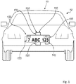
- FIG. 1 illustrates one embodiment of a digital license plate system 11 supporting a dynamic display that presents vehicle identification and registration information and can be arranged on an exterior of a vehicle 10.
- the system 10 includes a display system 100 for use on the exterior of a vehicle 10 includes a display 110, a vehicle speed sensor 120, and a processor 130 coupled to the vehicle speed sensor 120.
- the processor 130 is configured to implement one of three operational modes of the display system 100 based on the speed and state of the vehicle 10: a first operational mode, wherein a first content, including identification information of the vehicle 10 and/or registration information of the vehicle 10 is rendered on the display 110 at a first power consumption level; a second operational mode, wherein a second content, including a message, identification information of the vehicle 10, and/or registration information of the vehicle 10, is rendered on the display 110; and a third operational mode, wherein content is rendered on the display 110 at a second power consumption level less than the first power consumption level.
- the display system 100 preferably also includes a communication device 140 that allows content (for example, updated identification information, registration information, and/or messages) to be transferred to and from the display system 100.
- the display system 100 may also include a location sensor 160, for example, a Global Positioning System (GPS) device, a cellular tower location triangulation device, or any other suitable location sensor that determines the location of the vehicle 10 on which the display 110 is arranged.
- the location sensor 160 may provide a substantially general location or a substantially exact location of the vehicle.
- the display system 100 may include a storage device 150 that functions to store content; the processor 130 may retrieve content from the storage device 150 and render it on the display 110.
- the display system 100 may further comprise a sensor that determines the proximity of the vehicle 10 to a second vehicle.
- the digital license plate system 11 is preferably used for registered vehicles such as personal cars, trucks, motorcycles, rental cars, corporately-owned cars, or any other suitable type of vehicle.
- the display system 100 functions to render identification and/or registration information of the vehicle 10 that is preferably provided by an official authority, such as a Department of Motor Vehicles (DMV).
- the processor 120 renders the identification and/or registration information of the vehicle 10 on the display 110 such that a state vehicle code is followed, such as the size and dimension of the displayed area, the content, size, and lettering style of the information, and the visibility and reflectivity of the display 110.
- the processor 120 renders content on the display 110 such that the state vehicle code of the state in which the vehicle 10 is registered is followed; alternatively, such as in the embodiment of the invention that incorporates a location sensor (such as a GPS device), the processor 120 may render content on the display 110 such that the state vehicle code of the state in which the vehicle is located is followed.
- the display system 100 preferably functions to display a message in addition to the vehicle identification and/or registration information.
- the message is preferably provided by an advertiser, for example, an advertiser that is substantially unrelated to the user.
- the subject matter of the advertisement provided by the advertiser may be substantially unrelated to the driver and/or owner of the vehicle 10, and the advertisement may be substantially unrelated to the vehicle 10.
- the advertisement may be related to a demographic to which the driver and/or owner of the vehicle 10 belongs or to any other suitable characteristic of the driver and/or owner of the vehicle 10.
- the advertisement may also be selectable by the driver and/or owner of the vehicle 10, for example, via the Internet on a personal computer, via the internet on an internet-capable mobile phone, or via any other suitable method.
- the advertisement may also be substantially related to the vehicle 10, for example, a display system mounted to a Porsche may display advertisements that are targeted at a demographic with a brand affinity toward Porsches.
- the advertisements may be substantially related to the location of the vehicle 10, for example, if the vehicle 10 is traveling within the vicinity of a venue, an advertisement for the venue may be shown.
- the message may be provided by a law enforcement agency, for example, an emergency broadcast regarding a missing person (for example, an Amber or an Elder alert). Furthermore, if the vehicle 10 is reported stolen, the message may indicate that the vehicle 10 is stolen, thus allowing parties external to the vehicle to identify the vehicle 10 as such.
- a law enforcement agency for example, an emergency broadcast regarding a missing person (for example, an Amber or an Elder alert).
- the message may indicate that the vehicle 10 is stolen, thus allowing parties external to the vehicle to identify the vehicle 10 as such.
- the message may be any suitable type of message and may be controlled by any suitable party, for example, an official organization (for example, the DMV), the driver of the vehicle 10, the owner of the vehicle 10, a third party unrelated to the vehicle 10, or any other suitable party.
- the message may include additional details related to the vehicle 10, including the model of the vehicle 10, the smog check results of the vehicle 10, maintenance issues of vehicle 10, or any other suitable type of information related to the vehicle 10.
- the message may include details related to the driver of the vehicle 10, including organizations that the driver supports or belongs to (for example, the Girl Scouts, the San Francisco Giants baseball team, or a political party), a cause that the driver supports (for example, People for the Ethical Treatment of Animals (PETA) or cancer awareness), the demographic of the driver, or any other suitable type of information related to the driver.
- the message may also include official details regarding the driver; for example, the message may indicate that the driver is a doctor or a law enforcement officer, allowing people outside the vehicle 10 to direct requests to the driver when his services are desired.
- Official details may also include details relating to the driving history of the driver; for example, if the driver has an imperfect driving record, a notification may be rendered on the display in order to warn others in the vicinity of the vehicle.
- the message may include notifications for drivers in the vicinity of the vehicle 10, for example, traffic information or weather forecasts.
- the message may include details regarding the owner of the vehicle. This may be particularly useful when the vehicle 10 is a member of a fleet of cars, for example, a car rental agency, a moving truck rental agency, a government fleet, or any other suitable type of fleet.
- the message of the fourth example may indicate which fleet the vehicle 10 belongs to; this information may be used to identify vehicles, to advertise regarding the fleet (for example, if the vehicle 10 belongs to a rental car agency, the message may include an advertisement or a message for that particular rental car agency), or for any other suitable purpose.
- the message may be of any other suitable type of message.
- the display system 100 is preferably powered by a power source.
- the power source is preferably a power source of the vehicle 10, such as the accessories battery of the vehicle 10, the engine of the vehicle 10, or any other suitable power source of the vehicle 10.
- the display system 100 may include and be powered by a power source that is substantially independent from a power source of the vehicle 10.
- the power source of the display system 100 is preferably a battery, but may alternatively be a solar panel, wind generator, or any other suitable type of power source or combination of power sources.
- the display system 100 may include a power source that is rechargeable and coupled to a power source of the vehicle 10 that stores power from the vehicle 10 while the vehicle 10 is in operation and/or the ignition of the vehicle 10 is on.
- the power source of the display system 100 allows for power generated while the vehicle is in operation to be used at a later time by the display system 100.
- the display system 100 may be powered using any other suitable method and/or arrangement.
- the display 110 functions to display content, wherein content includes at least one of the identification information of the vehicle 10, registration information of the vehicle 10, and a message.
- the display 110 is operated by the processor 130 in one of the three operational modes.
- the display 110 is preferably of a substantially low power display, such as an LED display, an LCD display, an e-ink display, an organic LED display, an interferometric modulator display (iMoD), a display that uses electrophoretic deposition (EPD), a cholesteric liquid crystal display (ChLCDs), or any other suitable display.
- the display 110 may alternatively be a combination of the above display types.
- the display 110 preferably also has a substantially wide range of viewing angles.
- the display 110 is preferably also substantially thin, allowing the display 110 to replace existing license plates on the rear and/or front exterior of the vehicle.
- the display 110 is preferably of a width, height, and/or aspect ratio that is/are substantially similar to existing license plates.
- the display 110 may be substantially different than existing license plates (for example, in the case of the relatively narrow height of European license plates, the display 110 may be of a substantially different height).
- the display 110 may be of any other suitable dimension.
- the display 110 may also include a backlight.
- the backlight functions to control the light intensity of the information displayed by the display 110.
- the backlight preferably includes a plurality of degrees of light intensity.
- the processor 130 may select the degree of light intensity based upon the mode of operation.
- the processor 130 may also select the degree of light intensity based upon ambient light levels proximal to the display 110. For example, the degree of light intensity may be higher during the day and lower during the night.
- the display system 100 also includes a light sensor to detect the level of ambient light.
- the degree of light intensity of the display system 100 may also be selected based on the preferences of the driver, a law enforcement officer, or any other suitable party. However, the degree of light intensity of the display system 100 may be selected based on any other suitable criteria.
- the backlight may be a set of lights located substantially on the perimeter of the display 110 and that are directed toward the display 110. Alternatively, the backlight may be located substantially behind the display 110 and provide light from behind the display 110. However, the backlight may be of any other suitable arrangement.
- the backlight may be a series of low-power light sources, such as LEDs, but may alternatively be any other type of light source.
- the display may include a light-reflective surface that functions to illuminate the display 110 with reflected light.
- the light-reflective surface may be a mirror or any other suitable type of reflective material.
- the light-reflective surface may also be of a retroreflective material that reflects light back in the direction of the light source.
- the light-reflective surface may also be combined with a light source to more effectively illuminate the display 110, for example, the transflective materials used on freeway signs. However, any other suitable material or method may be used to illuminate the display.
- the vehicle speed sensor 120 functions to detect the speed of the vehicle 10.
- the vehicle speed sensor 120 is preferably a sensor that measures the actual velocity and/or acceleration of the vehicle 10, such as an accelerometer coupled to the vehicle 10 or a tachometer coupled to the drivetrain of the vehicle 10 and which measures the number of revolutions of a drivetrain component, such as a wheel, for a period of time in order to determine the speed of the vehicle 10.
- the vehicle speed sensor 120 couples to the speedometer of the vehicle 10 and/or an onboard computer of the vehicle 10; in this configuration, the speed sensor 120 functions to transmit information gathered by the speedometer and/or the onboard computer to the processor 130, rather than measure the vehicle speed directly.
- the vehicle speed sensor 120 may be any other suitable type of sensor that determines the actual speed and/or acceleration of the vehicle 10.
- the vehicle speed sensor 120 may be a sensor that measures the relative velocity and/or acceleration of the vehicle, for example an ultrasonic sensor or an infrared sensor that determines the speed of the vehicle relative to another object.
- the other object may be a stationary portion of the road or a nearby vehicle.
- the vehicle speed sensor 120 may determine the speed of the vehicle 10 using any other suitable method or sensor type.
- the processor 130 functions to render content on the display 110 based upon the operational mode of the display system 100: a first mode, wherein a first content is rendered on the display 110 at a first power consumption level, the first content including identification information of the vehicle 10 and/or registration information of the vehicle 10; a second mode, wherein a second content is rendered on the display 110, the second content including a message and possibly including identification information of the vehicle 10 and/or registration information of the vehicle 10; and a third mode, wherein content is rendered on the display 110 at a second power consumption level that is less than the first power consumption level.
- content rendered in the third operational mode includes the identification and registration information of the vehicle 10.
- content rendered in the third operational mode includes a message in addition to the identification and/or registration information of the vehicle 10.
- content rendered on the display 110 in the third operational mode may include any other information or messages or any combination thereof.
- the processor 130 is preferably coupled to the vehicle speed sensor 120.
- the speed determined by the vehicle speed sensor 120 may be the actual speed of the vehicle 10 or may alternatively be the speed of the vehicle 10 relative to another object (for example, a neighboring vehicle).
- the processor 130 preferably selects the operational mode of the display system 100 based on the speed and power state of the vehicle 10.
- a device other than the processor such as the onboard computer of the vehicle 10, a law enforcement officer, a second processor connected to a remote server, or any other suitable device or institution may select the operational mode of the display system 100.
- the processor 130 preferably operates the display 110 in the first and second operational modes when the vehicle 10 is on, and the processor preferably operates the display 110 in the third operational mode when the vehicle 10 is off.
- the vehicle 10 is preferably considered “on” when the driver turns any portion of the vehicle 10 on.
- there is a plurality of “on” states for example, a first "on” state in which basic functionality, such as opening and closing windows, is allowed; a second "on” state in which more advanced and/or higher-power functionality, such as ventilation systems or the sound system, is allowed; and a third “on” state in which the vehicle may be driven (or, in other words, the ignition is on).
- the vehicle 10 may be considered “off otherwise. In the "off state, certain portions of the vehicle may still be “on”, for example, security sensors, key proximity sensors (such as keyless entry), or any other type of substantially-low-power functionality.
- the vehicle 10 may be considered “on” when the ignition is on and considered “off when the ignition is off, regardless of any other functionality that the vehicle may provide to the driver. Yet alternatively, the vehicle 10 may be considered “on” when the presence of a person is detected within the vehicle and “off' when there is no one within the vehicle. The vehicle 10 may also be considered off when the emergency brake or transmission parking brake of the vehicle 10 is engaged, regardless of the state of the ignition or presence of a person within the vehicle 10. However, the vehicle may be considered “on” and "off using any other suitable criteria.
- the processor 130 preferably operates the display 110 in the first operational mode when the vehicle 10 is at a first speed and preferably operates the display 110 in the second operational mode when the vehicle 10 is at a second speed lower than the first speed.
- the second speed is preferably substantially zero speed, or substantially close to zero speed. This allows for identification and/or registration information of the vehicle 10 to be substantially visible while the vehicle 10 is in motion (the first speed), as shown in FIG. 1 . This allows any party external to the vehicle 10 to visually access the information rendered on the display 110 in a manner similar to that used to visually access information on a static (or stamped) license plate.
- the processor 130 operates the display 110 in the second operational mode and renders the second content on the display 110 when the vehicle 10 is on and at the second speed, wherein the second speed is preferably zero speed or a substantially slow speed, such as when the vehicle is moving slowly through heavy traffic.
- the identification and/or registration information also depicted may consume a smaller portion of the display area in the second operational mode as compared to the first operational mode. Because the identification and registration information is depicted in a is smaller size on the display 110 when a message is displayed concurrently with the vehicle 10 information, the visibility of the identification and registration information may be less in the second operational mode than in the first operational mode. Alternatively, the identification and/or registration information rendered on the display 110 in the second operational mode may be of the same or similar format (for example, size and layout) as in the first mode, but the message may be rendered on the display to overlap the identification and/or registration information.
- the message may be displayed only under such conditions as when the vehicle is stopped or nearly stopped so that decreased visibility of the identification and/or registration information does not occur when the vehicle 10 is moving at a substantial speed; however, the additional functionality of displaying the message when the vehicle is at the second speed still remains. Additionally, the message may provide an undesired distraction for a party outside of the vehicle 10 while the vehicle 10 is in motion, and thus, by only displaying the message while the vehicle is stopped or nearly stopped, the possibility of distraction may be substantially reduced.
- the processor 130 may alternatively operate the display 110 in the first and second operational modes at any other suitable speed arrangement.
- the display system 100 may enhance legibility of the information for a party outside of the vehicle 10 by horizontally mirroring content rendered on the display 110 when the display 110 is mounted on the front exterior of the vehicle 10; in this variation, content rendered on the display may be read in the correct orientation by a party viewing the display 110 in a rearview or side mirror of a second vehicle located ahead of the vehicle 10.
- the processor may render content on the display 110 by any other means or arrangement such that distraction caused by the display 110 is reduced and legibility of the displayed content is improved.
- the processor 130 preferably functions to operate the display 110 in the third operational mode when the vehicle 10 is off.
- the third operational mode preferably displays identification and registration information of the vehicle 10 at a second lower power consumption level that is less than the first power consumption level.
- a message is rendered on the display 110 in addition to the identification and registration information of the vehicle 10, although any one or combination of a message, identification information of the vehicle 10, registration information of vehicle 10, or any other information may be rendered on the display 110 when in the third operational mode.
- the power available to the display system 100 may be less than when the vehicle is on.
- the display system 100 may be utilizing energy that was stored from another period of time when the vehicle was on.
- the display system 100 may be utilizing energy that was stored from another period of time when the vehicle was on.
- the operation of the display 110 in the third operational mode may reduce the power consumption of the display system 100 in a variety of arrangements.
- the display 110 may be turned off at a first time and turned on at a second time.
- the display 110 may be timed to cycle on and off at specific time intervals, for example, every five minutes.
- the driver, the owner, or any other suitable party may adjust the intervals. This allows the display 110 to be turned off for a length of time and turned on for another length of time.
- the length of time that the display 110 is turned off is preferably substantially longer than the length of time that the display 110 is turned on, which substantially decreases the power consumption of the display 110.
- the processor when in the third operational mode, content may be rendered on the display 110 in colors that require less power to display, as compared to when operating in the first operational mode.
- the processor may operate the display 110 by any other means that reduces power consumption of the display 110 when in the third operational mode, as compared to the first operational mode.
- the processor 130 may reduce the power consumption level of the processor 130 when in the third operational mode, for example, by reducing clock speed, shutting down auxiliary functions such as transmitting data to and/or receiving data from the communications device 140, or any other method to reduce power consumption of the processor 130.
- the light intensity of the display 110 may be substantially identical to the light intensity of the first and/or the second operational modes.
- the light intensity of the display 110 may be substantially less in the third operational mode than in the first and/or second operational modes. However, any other suitable light intensity may be used in the third operational mode.
- the display may be continuously on when operating in the third operational mode but at a substantially lower light intensity than in the first and/or second operational modes.
- the backlight of the display 110 may be at the lowest light intensity in the third mode.
- the backlight of the display 110 may be turned off, allowing only the e-ink, which is bistable and does not require additional power to maintain, to be visible.
- the method and arrangement to decrease the power consumption of the display 110 in the third operational mode is preferably one of the two above variations, but may alternatively be a combination of the above variations or any other suitable method or arrangement.
- the processor 130 may alternatively operate the display 110 in a fourth operational mode.
- the fourth mode may be determined by communication through the communication device 140.
- the communication device 140 may communicate with a law enforcement agency and may indicate to the processor 130 that the vehicle 10 has been stolen.
- the processor 130 may then operate the display 110 in a fourth operational mode in which a notification that the vehicle 10 is a stolen vehicle is rendered on the display 110.
- the fourth mode may alternatively be of any other suitable type and actuated by any other suitable method.
- the communication device 140 functions to allow content, information, and/or data to be transferred to and from the display system 100.
- the communication may be conducted with an official organization (such as a DMV office or a law enforcement agency), a content database, the driver of the vehicle, the owner of the vehicle, or any other suitable party.
- the communication device may transmit and/or receive information regarding vehicle identification and/or registration information, vehicle maintenance information, driver information, vehicle location information (for example, in the variation of the display system 100 that includes a GPS location device or accesses GPS location services), updated advertisements, or any other suitable type of information.
- the communication device 140 is preferably of a wireless communication type, for example, one that communicates with cellular phone towers, Wi-Fi hubs, or any other suitable type of wireless communication.
- the communication device 140 may be a wired communication device.
- updated information is transferred when the display system 100 is "plugged in" to an updating device, for example, a computer at a maintenance facility, at a DMV office, or any other suitable location, or another vehicle and/or display system 100 that has wireless communication capabilities.
- the communication device 140 may also include a communication processor that functions to interpret communications to and/or from the display system 100.
- the communication processor is preferably separate from the processor 130, but may alternatively be the processor 130.
- the communication processor may function to encrypt and/or decrypt communications to and/or from the display system 100.
- the encryption/decryption may be any one of a variety of authentication and encryption schema.
- the communication processor may also function to encrypt data to encryption standards such as the Data Encryption Standard (DES), Triple Data Encryption Standard (3-DES), or Advanced Encryption Standard (AES).
- DES Data Encryption Standard
- 3-DES Triple Data Encryption Standard
- AES Advanced Encryption Standard
- the communication device 140 may allow any other suitable type of communication and may be of any other suitable arrangement.
- the communication device 140 may receive content, information, and/or data from a content database.
- the content database is arranged substantially remote from the processor 130.
- the content database also preferably contains content provided by an institution, for example, an advertiser, a school, a record company, or a sports team or venue; content provided by the institution preferably includes advertisements.
- the content database may contain content provided by the driver and/or owner of the vehicle 10, for example, a message composed by the owner of the vehicle 10 congratulating a child upon graduation from high school.
- any other suitable party may provide content to the content database, and the content database may include a combination of advertisements from one or more institutions and personal messages from one or more individuals.
- content on the content database is accessed by the processor 130 via the communication device 140 and stored on the storage device 150.
- the storage device 150 is arranged substantially proximal to the display 110, such as within the vehicle 10 or within a housing containing the display 110; however, the storage device 150 may be located remotely from the vehicle 10, such as on a hard drive connected to a remote server.
- content on the content database is accessed via the communication device 140 in real time and then rendered on the display 110, thereby bypassing storage of content on the storage device 150.
- content from the remote message database may be accessed by any other means before being rendered on the display 110.
- the storage device also functions as the content database, wherein content from at least one institution or individual, such as those listed above, may be stored on the storage device and also selected by the driver and/or owner of the of vehicle 10 to be rendered on the display 110.
- the storage device 150 of the display system 100 also functioning as a content database, may be accessed by a second display system separate from the display system 100, such as a display system arranged on a second vehicle.
- any other suitable party may select the content to be rendered on the display 110 from the content database.
- content on the content database may be selected, accessed and/or modified by the driver and/or owner of the vehicle 10, or any other suitable party, via an interface.
- the interface is internet-based and accessible via a web browser, for example, on a mobile smart phone or on a computer.
- the driver and/or owner of the vehicle 10 may access interface with an internet-capable mobile phone, then log into the content database and select content (for example, a San Francisco Giants Baseball banner) he wishes to be rendered on the display 110.
- the content database stores vehicle registration information, and upon the renewal of the registration of the vehicle 10, a DMV representative may access the content database via a computer equipped with the interface and then update the registration information of the vehicle 10 on the content database; the communication device 140 may then retrieve the updated registration information from the content database and the registration information subsequently rendered on the display 110 may reflect the renewal.
- the interface may be a handheld device that is hardwired, or physically "plugged in", to the display system 100.
- the interface may or may not be removable from the display system 100.
- the interface may not couple to the content database via the communication device 140, but instead only provide the driver and/or owner of the vehicle 10, or any other suitable party, to access content already located on the display system 100, such as on the storage device 150 arranged substantially proximal to the display 110.
- a law enforcement officer upon pulling over the driver of the vehicle 10 for a traffic violation, may hook up to the display system 100 arranged on the vehicle 10 a device equipped with the interface, wherein the interface provides access to the current identification and/or registration information of the vehicle 10.
- the interface may permit access to any content contained in any other device coupled to the display system 110 and by any other means.
- the communication device 140 may transmit data regarding the rendering of a particular content on the display 110.
- an advertisement is included in the content rendered on the display 110, and the communication device 140 transmits data regarding the rendering of the advertisement on the display 110.
- This data may include, for example, how long the advertisement was displayed, when it was displayed, and where it was displayed.
- this data could be collected and/or stored by the processor 130, although it could be collected and stored by any other device or means.
- this information is used to determine the magnitude or type of an award granted to the driver and/or owner of the vehicle 10.
- the driver and/or owner of the vehicle 10 may receive a monetary award commensurate with the length of time that the advertisement was rendered on the display 110; alternatively, the owner and/or driver of the vehicle 10 may receive one or more tickets to a baseball game featuring this team in return for displaying the advertisement in an area with a relatively low attendance at baseball games.
- any other method may be used to grant an award of any other type to the driver and/or owner of the vehicle 10 in return for the rendering of content on the display 110.
- the sensor for determining the proximity of the vehicle 10 to a second vehicle functions to indicate to the processor 120 to modify content rendered on the display 110.
- the processor 120 preferably renders a message, such as an advertisement, on the display 110 when the second vehicle is substantially proximal to the vehicle 10 (such as in the second mode); the processor 120 preferably renders the identification and registration information of the vehicle 10 on the display 110 when the sensor detects that no second vehicle is substantially proximal to the vehicle 10 (such as in the first mode or the third mode).
- the sensor may be a RADAR detector, a LIDAR detector, an IR transmitter-photoresistor pair, a camera, or any other suitable device configured to detect the proximity of the vehicle 10 to a second vehicle.
- the camera may be configured to detect identification information of the second vehicle (such as the license plate number of the second vehicle); this information may be used to determine the owner of the second vehicle and obtain information relating to the owner of the second vehicle.
- the processor 120 may then modify content rendered on the display 110 based upon the demographic of the owner of the second vehicle, such as by displaying an advertisement for discount prescription medications if the owner of the second vehicle is determined to be at least sixty years of age; by displaying an advertisement for a women's fashion store if the owner of the second vehicle is determined to be female; or by displaying driver information if the second vehicle is determined to be owned by or used by a law enforcement agency.
- identification information of the second vehicle may be transmitted to a database of vehicle identification information, wherein the database returns information about the owner of the second vehicle 10, such as age, ethnicity, or gender; the database may be maintained by an entity such as a DMV or the American Automobile Association (AAA).
- the camera may be configured to determine directly the demographic of the driver of the second vehicle (for example, by matching the driver to a specific ethnicity by with facial recognition software) or the response of the driver of the second vehicle to a message rendered on the display 120.
- the response of the driver of the second vehicle may be used to pick an alternative message that may produce a more favorable response if the initial response is negative, or to choose a similar message if the first response is positive.
- the camera may be used to measure the level of ambient light substantially proximal to the vehicle 10 such that content may be rendered on the display at an appropriate light level; for example, the brightness of the display may increase if the camera determines a high level of sunlight near the vehicle 10.
- the sensor may detect any other information relevant to the second vehicle and indicate to the processor 120 to modify content rendered on the display based upon any other variable.
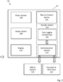
- FIG. 2 illustrates various systems, sub-systems, or modules that can be incorporated into a digital license plate system 200, along potential interacting agents such as vehicle systems 218, vehicle occupants, or third party persons or automated systems 220.
- a digital license plate 202 can be mounted on a vehicle.
- Systems within the digital license plate can include, but are not limited to, a power system 204, thermal control system 206, and sensor system 208.
- An electronic security system 210 limits unauthorized access to data logged and distributed via a data logging and interface system 212, or any received/transmitted communications through communication system 214. Received data can be used to determine or update information presented by display 216.
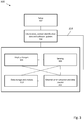
- FIG. 3 illustrates a method for operation of one embodiment of a digital license plate system.
- the digital license plate can be ready for initialization 304 on vehicle startup (or alternatively, on vehicle stop), and can use timers or sensors to help identify context, location, or display presets for the digital license plate.
- Data uploading/downloading can be initiated, and any firmware/software updates completed.
- changes 306 to the display can occur in response to sensed data 308, from data storage or analysis system 310, or as a result of external communication and data transfer 312.
- sensed or stored data can be transmitted or received, and the sensors activated, deactivated, or sensor data analyzed based on internal triggers or externally received data.
- data can be transferred (via line 314) back to the initialization step 304.
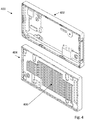
- FIG. 4 depicts two views 400 of a bezel, illustrating cooling fins.
- the view 400 in FIG. 4 shows a bezel 402 that functions as a frame surrounding digital display 110.
- 404 is an alternate view of bezel 402, showing a set of cooling fins 406.
- Cooling fins 406 function to radiate heat away from digital display 110, thereby helping reduce the heating rate associated with digital display 110.
- heat conduits may be included as a part of bezel 402, where heat conduits contact circuit board components directly to funnel heat away, and may also include some sort of heat-transfer compound (possibly in the form of a gel or paste) to help with heat conduction.
- Other embodiments may use thermoelectric cooling (e.g. Peltier devices) to provide active cooling for display system 110.
- a suitable thermal control system such as discussed briefly with respect to FIG. 2 is also useful for ensuring reliable operation under a range of conditions.
- display system 100 may be mounted on the exterior of a vehicle, and may be subject to a range of temperatures. Furthermore, display system 100 generates heat due to power dissipation in the associated components such as display 110. In some conditions, it might be important to prevent display system 100 from overheating. Presented below is a description of how overheating effects in display system 100 can be reduced.
- One strategy to regulate the amount of heat generated is to reduce the brightness of display 110 in accordance with the detected temperature associated with display system 100.
- the control logic for temperature regulation is created based on data collected from experimental bench testing of the device. Some important variables of the control logic to determine the upper temperature limit at which to restrict the device are the amount to decrease the brightness when the limit is reached; the lower limit temperature at which to begin increasing the brightness; the amount to increase the brightness once the device is in a safe temperature range; the sample rate for checking the brightness and temperature; and the maximum brightness level, which is varied depending upon the ambient light levels.
- the current maximum allowable temperature of the device is set at a defined temperature as read by a system-on-microprocessor (SOM) sensor. To ensure that this temperature is not reached, the upper temperature limit needs to be some amount lower than this.
- SOM system-on-microprocessor
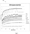
- FIG. 5 shows a test run where the device was being restarted after running for a while, with no time to cool down. This is a worst-case scenario for SOM temperatures. In this data set the SOM makes jumps of 8.5°C in 60 seconds. Assuming sampling data every 60 seconds for the control logic, the plate should be stopped at 8.5°C less than the maximum temperature of 79.2°C. For this reason, the temperature at which to restrict the device is set to 70.7°C.
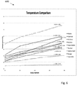
- FIG. 6 illustrates the effect decreasing display brightness has on system temperature.
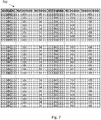
- FIG. 7 depicts a table 700 that shows how temperature decrease correlates with 10%, 15% and 20% decrement steps in display brightness.
- FIG. 8 depicts a flow diagram illustrating one embodiment of a method 800 to implement brightness control logic.
- the method samples the SOM temperature and display brightness at defined time intervals (e.g. every 60 seconds).
- the method checks to see whether the temperature is greater than or equal to 70.7°C. If the temperature is greater than or equal to 70.7°C, the method proceeds to 806, where the method reduces display brightness by 15%, after which the method returns to 802.
- the method goes to 808, where it checks to see whether the temperature is less than or equal to 67°C. If the temperature is not less than or equal to 67°C, then the method returns to 802.
- the method goes to 810, where it checks to see if a set point has been reached, where the term "set point" is used to refer to a predetermined brightness value. If the set point has been reached, then the method returns to 802, otherwise the method goes to 812, where it increases the display brightness by 5% or any other preset value and returns bask to 802.
- a lower temperature threshold is set, below which point the screen brightness will be increased.
- the brightness should begin to increase back towards the set point slowly so that the device does not get stuck in a loop of increasing and decreasing the brightness. Since brightness is being stepped down at 15% increments, the brightness will be increased at 5% increments once the temperature is below the set value. This built-in hysteresis prevents it from getting stuck in a loop of changing the brightness. In some embodiments, a quicker sampling rate may allow for finer adjustment of the brightness at the risk of false actions taken due to noise in the temperature sensor.
- the brightness set point can be generated from the ambient light sensor in the device on boot up, and recalibrated every 60 seconds thereafter.
- FIG. 9 is a flowchart 900 illustrating plate temperature management. Temperature management is accomplished by varying the brightness of the screen, thus varying power consumption which, in turn, directly affects heat dissipation and the associated ambient temperature.
- the method sets the value of the parameter maxBrightness based on an ambient light sensor reading.
- the method reads a temperature value, assigning it to the variable tempValue.
- the method compares tempValue to a predetermined maximum temperature value, denoted by the variable maxTemp.
- the value of maxTemp may be 75°C.
- the method proceeds to 908, where the method compares tempValue to a predetermined minimum temperature value, denoted by the variable minTemp. In some embodiments, the value of minTemp may be 45°C. If, at 908, the method determines that tempValue is not less than minTemp, the method proceeds to 910, where it sets the target brightness level, denoted by the variable targetBrightness, to the current brightness value, denoted by the variable curBrightness. The method then goes to 914, where the brightness of the screen is adjusted to the value of targetBrightness, after which the method returns to 902.
- targetBrightness is calculated as a scaled-down version of the current brightness, where the current brightness is denoted by the variable curBrightness.
- targetBrightness may be assigned a value of 0.92 X curBrightness.
- the method checks to see whether targetBrightness is less than a minimum allowable brightness value, denoted by a variable minBrightness. If targetBrightness is not less than minBrightness, the method goes to 914, where the brightness of the screen is adjusted to the value of targetBrightness, after which the method returns to 902.
- targetBrightness is less than minBrightness
- the method goes to 920, where targetBrightness is assigned the value of minBrightness.
- the method then goes to 914, where the brightness of the screen is adjusted to the value of targetBrightness, after which the method returns to 902.
- targetBrightness is calculated as a scaled-up version of the current brightness, where the current brightness is denoted by the variable curBrightness. In some embodiments, targetBrightness may be assigned a value of 1.5 X curBrightness.
- the method checks to see whether targetBrightness is greater than a maximum allowable brightness value, denoted by a variable maxBrightness. If targetBrightness is not greater than maxBrightness, the method goes to 914, where the brightness of the screen is adjusted to the value of targetBrightness, after which the method returns to 902.
- targetBrightness is greater than maxBrightness
- the method goes to 926, where targetBrightness is assigned the value of maxBrightness.
- the method then goes to 914, where the brightness of the screen is adjusted to the value of targetBrightness, after which the method returns to 902.
- digital display 110 may be a bistable display. Under low operating temperatures, a bistable display may need to be externally heated for the bistable display to correctly transition. Under high operating temperatures, there can be difficulties in switching unless the bistable display is maintained below a defined temperature, or at least temporarily cooled. Due to the differences in the operating temperatures of bistable displays and an LCD, temperature controls might be programmed differently with the bistable display versus the LCD.
- FIG. 10 is a cartoon detail 1000 of pigmented microspheres in an electrophoretic display containing white and black pigment material.
- bistable displays are commonly available from E Ink Corporation, and as illustrated in FIG. 10 , include a microsphere 1010 containing a transparent oil, positively charged white pigments 1012 and negatively charged black pigments 1014. Bistable switching of the microsphere 1010 orientation is enabled by transparent electrode 1020 and addressable pixel electrodes 1022.
- the electrophoretic dispersion has one type of charged pigment particles dispersed in an oil or oil mixture of a contrasting color.
- the pigment particles migrate electrode of polarity opposite that of the pigment particles.
- the color showing at the transparent electrode 1020 may be either the color of the solvent or the color of the pigment particles. Reversal of electrode polarity will cause the particles to migrate back to the opposite pixel electrode 1022, thereby reversing the color.
- white pigment particles can be formed from, or associated with, materials that reflect infrared light. This improves readability using infrared sensitive camera systems.
- the white pigment particles can be formed from, or associated with, materials that fluoresce or are phosphorescent.
- the white pigment particles can be formed from, or associated with, heat rejecting or heat absorbing materials that reduce or increase temperature to help maintain the bistable display of the digital license plate within operational temperature limits.
- a bistable display may need to be externally heated for the bistable display to correctly transition.
- the e-ink may need an external source of heat in order for it to be able to transition, since the lower bound of its operating temperature range is higher than LCDs.
- Attached heating elements, heating pipes, battery or vehicle powered heating elements can all be used to ensure that the bistable display is maintained or temporarily brought above the minimum display switching temperature when switching is required.
- Use of a heating element allows, for example, activation of a heater to bring the display above the minimum display switching temperature, followed by deactivation of the heater and consequent drop in temperature below the minimum display switching temperature.
- Other components that might be heated other than the bistable display may include any associated circuit boards, and the battery system.
- operation of the bistable display can be adjusted to compensate.
- the digital license plate can be set to display only the legally required information. Advertisements that could interfere with display of legally required information or dynamic displays that could partially or completely fail to switch due to cold temperatures would not be allowed. In effect, for example, a vehicle maintained in a heated garage would be able to display the full range of visual effects possible in the digital license plate. If the vehicle moves into an environment with sub-zero temperatures, a temperature sensor could provide warning data of low temperature conditions, the digital license plate would switch to a display of only the legally required information or information that would not interfere with viewing of the legally required information. Similarly, embodiments that with active or passive cooling systems can support methods to ensure that the digital license plate will switch to a display of only the legally required information or information that would not interfere with viewing of the legally required information before temperatures reach a maximum display switching temperature.
- Critical temperatures vary according to material and type of display.
- an e-ink bistable display may have a normal operating temperature range above 0 degrees Celsius and below 50 degrees Celsius. Actions to compensate for low or high heat conditions can begin before a critical temperature is reached.
- a display pattern that impacts reflectivity can be adjusted to increase reflectivity as the sensed temperature increases above 40 degrees Celsius.
- Optional cooling elements can be activated if the temperature continues to increase, and the display can be locked into a non-switching state if temperature continues to rise, with the digital license plate acting to display only the legally required information or information that would not interfere with viewing of the legally required information.
- display pattern reflectivity
- reflectivity can be adjusted to decrease reflectivity (i.e.
- Optional heating elements can be activated if the temperature continues to decrease, and the display can be locked into a non-switching state if temperature continues to fall, with the digital license plate acting to display only the legally required information or information that would not interfere with viewing of the legally required information.
- actions taken to compensate for high or low heat conditions begin within 15, 10, or 5 degrees Celsius of the critical temperature, and can be ordered so that actions requiring little or no power or having a low visual impact are implemented before actions requiring a substantial amount of power or having a greater impact on display messaging are implemented.
- temperature of a display can be directly or indirectly measured.
- Electronic thermometers with associated temperature control modules can be attached to the display, attached near or in the vicinity of the display, or attached somewhere on a vehicle.
- Ambient temperatures can be measured, and an indirect determination of likely display temperature can be made.
- predicted temperatures can be used. For example, if the digital license plate receives predicted or calculated overnight temperature information, protective measures can be immediately engaged when the vehicle is parked near the end of a day. While not as accurate as direct measurement of the display temperature, ambient or other indirect temperature measurement can be accurate enough to engage protective measures when needed as critical temperatures are approached.
- a display system supporting modifiable heat relevant display parameters includes a temperature sensor positioned to measure temperature of the display system.
- a temperature control module can be connected to the temperature sensor and configured to modify heat relevant display parameters as critical temperatures are approached.
- Modifiable heat relevant display parameter includes brightness, with brightness being increased as critical low temperatures are approached and decreased as critical high temperatures are approached.
- the modifiable heat relevant display parameter includes a displayed pattern to modify reflectivity, with the displayed pattern being modified to increase heat absorption as critical low temperatures are approached and modified to decrease heat absorption as critical high temperatures are approached.
- the display can be composed of multiple homogeneous tiles, a large heterogenous display with inset tiles (e.g. a bistable or electrophoretic display with LED display sections), or have distinct color and bistable sections.
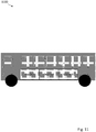
- the display system can control multiple additional displays positioned on the interior or exterior of a vehicle. For example, such displays may be tiled and placed on the side of a bus, as shown in FIG. 11 . Tiling displays may increase the number of options available to present media to an intended audience.
- FIG. 4 shows the displays 1100 placed on the side of a bus; a similar set of tiled displays may be implemented on the back of the bus as well.
- the systems and methods described herein can all be extended to include display ensembles as shown in FIG. 11 .
- Some embodiments include a larger display (say 16" x 16" for example), a portion of which can show the plate image, while the rest can be used for static messaging. This way messages and plate image can be displayed simultaneously.
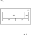
- FIG. 12 is a diagram illustrating a display 1200 comprised of multiple sub-displays.
- a display may be comprised of sub-displays of similar or different kinds tiled together.
- display 1200 may have an outer frame display 1202, an inner sub-display 1204, an inner sub-display 1206, an inner sub-display 1208 and an inner sub-display 1210.
- Outer frame display 1202 and inner sub-display 1204-1210 may be configured to display different media content.
- outer frame display 1202 may be configured to display vehicle license and registration information, while sub-display 1204-1210 may display different advertising and/or promotional messages.
- sub-display 1206 could be, for example, a color OLED display able to accurately display a replica of a colored annual registration sticker.
- outer frame display 1202 and sub-display 1204-1210 may be comprised of different display kinds.
- outer frame display 1202 may be a bistable display
- sub-display 1204 may be an OLED display
- sub-display 1206 may be an LCD display
- sub-display 1208-1210 may each be a bistable display.
- Measures to prevent display system from damage from road debris or similar hazards may include physical protective covers made from, for example, Plexiglas or sapphire crystal. Hydrophobic coatings may also be applied to the exterior surface of display system to prevent damage due to exposure to liquids such as water. In other embodiments, self-cleaning glass using nanocrystalline titanium dioxide coatings, plasma-chemical roughening, photocatalytic cleaning structures, molded polymeric layers, or other suitable hydrophobic or hydrophilic system can be used. Thermal protection can be provided by an IR-blocking coating.
- the display system may also be integrated into the vehicle structure itself. For example, a curved or flexible display may be used to conform aesthetically to a vehicle design. An embodiment of display system 100 may, for example, be conformably integrated into a bumper of a vehicle.
- FIG. 13 is a block diagram 1300 illustrating display communication protocols.
- low voltage differential signaling (LVDS) communication interface may be implemented between a microcontroller 1302 and a display 1 1304.
- a gate/source interface may be implemented between a microcontroller 13013 and a display 2 1308.
- a low voltage differential signaling or serial peripheral interface (LVDS/SPI) communication interface may be implemented between a microcontroller 1310 and a display 3 1312.
- HDMI may be used to implement the communication link between the processing device and the display device, where the processing device may be a microcontroller such as microcontroller 1302 or any other suitable processing device such as a microprocessor, a digital signal processor, a field-programmable gate array and so on.
- the processing device may be a microcontroller such as microcontroller 1302 or any other suitable processing device such as a microprocessor, a digital signal processor, a field-programmable gate array and so on.
- Display 1 1304, display 2 1308, and display 3 1312 may be any of an LCD display, a TFT LCD display with and LED backlight, a bistable display with a front LED light, or any other suitable display. Any combination of signaling methods may be used to communicate between a microcontroller and a display, including LVDS, SPI, parallel port interface, serial port interface, RS232, and so on. In certain embodiments, one or more displays controlled by the foregoing discussed signaling methods and protocols can be positioned at a distance from the digital license plate, either within or on the exterior of the vehicle.
- Embodiments in accordance with the present disclosure may be embodied as an apparatus, method, or computer program product. Accordingly, the present disclosure may take the form of an entirely hardware-comprised embodiment, an entirely software-comprised embodiment (including firmware, resident software, micro-code, etc.), or an embodiment combining software and hardware aspects that may all generally be referred to herein as a "circuit," "module,” or “system.” Furthermore, embodiments of the present disclosure may take the form of a computer program product embodied in any tangible medium of expression having computer-usable program code embodied in the medium.
- a computer-readable medium may include one or more of a portable computer diskette, a hard disk, a random access memory (RAM) device, a read-only memory (ROM) device, an erasable programmable read-only memory (EPROM or Flash memory) device, a portable compact disc read-only memory (CDROM), an optical storage device, and a magnetic storage device.
- Computer program code for carrying out operations of the present disclosure may be written in any combination of one or more programming languages. Such code may be compiled from source code to computer-readable assembly language or machine code suitable for the device or computer on which the code will be executed.
- Embodiments may also be implemented in cloud computing environments.
- cloud computing may be defined as a model for enabling ubiquitous, convenient, on-demand network access to a shared pool of configurable computing resources (e.g., networks, servers, storage, applications, and services) that can be rapidly provisioned via virtualization and released with minimal management effort or service provider interaction and then scaled accordingly.
- configurable computing resources e.g., networks, servers, storage, applications, and services
- a cloud model can be composed of various characteristics (e.g., on-demand self-service, broad network access, resource pooling, rapid elasticity, and measured service), service models (e.g., Software as a Service (“SaaS”), Platform as a Service (“PaaS”), and Infrastructure as a Service (“IaaS”)), and deployment models (e.g., private cloud, community cloud, public cloud, and hybrid cloud).
- service models e.g., Software as a Service (“SaaS”), Platform as a Service (“PaaS”), and Infrastructure as a Service (“IaaS”)
- deployment models e.g., private cloud, community cloud, public cloud, and hybrid cloud.
- each block in the flow diagrams or block diagrams may represent a module, segment, or portion of code, which comprises one or more executable instructions for implementing the specified logical function(s).
- each block of the block diagrams and/or flow diagrams, and combinations of blocks in the block diagrams and/or flow diagrams may be implemented by special purpose hardware-based systems that perform the specified functions or acts, or combinations of special purpose hardware and computer instructions.
- These computer program instructions may also be stored in a computer-readable medium that can direct a computer or other programmable data processing apparatus to function in a particular manner, such that the instructions stored in the computer-readable medium produce an article of manufacture including instruction means which implement the function/act specified in the flow diagram and/or block diagram block or blocks.
Claims (13)
- Ein digitales Nummernschild (202), aufweisend:ein Anzeigesystem (216), das modifizierbare wärmebezogene Anzeigeparameter unterstützt;einen Temperatursensor, der so angeordnet ist, dass er die Temperatur des Anzeigesystems (216) misst; undein Temperatursteuermodul (206), das mit dem Temperatursensor verbunden und so konfiguriert ist, dass es wärmebezogene Anzeigeparameter bei Annäherung an kritische Temperaturen ändert;dadurch gekennzeichnet, dass
die veränderbaren wärmebezogenen Anzeigeparameter ein angezeigtes Muster umfassen zur Veränderung des Reflexionsvermögens. - Digitales Nummernschild (202) nach Anspruch 1, wobei die kritischen Temperaturen unter 0 Grad Celsius und über 50 Grad Celsius liegen.
- Digitales Nummernschild (202) nach Anspruch 1, wobei die veränderbaren wärmebezogenen Anzeigeparameter die Helligkeit beinhalten.
- Digitales Nummernschild (202) nach Anspruch 1, wobei zu den veränderbaren wärmebezogenen Anzeigeparametem die Helligkeit gehört, wobei die Helligkeit erhöht wird, wenn sich kritische niedrige Temperaturen nähern, und verringert wird, wenn sich kritische hohe Temperaturen nähern.
- Digitales Nummernschild (202) nach Anspruch 1, wobei das angezeigte Muster durch das Temperatursteuermodul (206) modifiziert wird, um die Wärmeabsorption zu erhöhen, wenn sich kritische niedrige Temperaturen nähern, und durch das Temperatursteuermodul (206) modifiziert wird, um die Wärmeabsorption zu verringern, wenn sich kritische hohe Temperaturen nähern.
- Digitales Nummernschild (202) nach Anspruch 1, wobei das Anzeigesystem (216) ferner ein LCD umfasst.
- Digitales Nummernschild (202) nach Anspruch 1, wobei das Anzeigesystem (216) ferner eine OLED-Anzeige umfasst.
- Digitales Nummernschild (202) nach Anspruch 1, wobei das Anzeigesystem (216) ferner eine bistabile Anzeige umfasst.
- Digitales Nummernschild (202) nach Anspruch 1, wobei das Anzeigesystem (216) ferner ein Heizelement umfasst.
- Digitales Nummernschild (202) nach Anspruch 1, wobei das Anzeigesystem (216) ferner aufweist:
eine Vielzahl von Unteranzeigen, wobei mindestens eine Unteranzeige bistabil ist und mindestens eine Unteranzeige eine Farb-LCD- oder OLED-Anzeige ist. - Verfahren zum Betrieb eines digitalen Nummernschildes (202), das die folgenden Schritte umfasst:Messung der Temperatur eines Anzeigesystems (216), das modifizierbare wärmebezogene Anzeigeparameter unterstützt; undÄnderung der wärmebezogenen Anzeigeparameter bei Annäherung an kritische Temperaturen; dadurch gekennzeichnet, dassdie veränderbaren wärmerelevanten Anzeigeparameter ein angezeigtes Muster umfassen, um die Reflektivität zu verändern, wobei das angezeigte Muster verändert wird, um die Wärmeabsorption zu erhöhen, wenn sich kritische niedrige Temperaturen nähern, und verändert wird, um die Wärmeabsorption zu verringern, wenn sich kritische hohe Temperaturen nähern.
- Verfahren zum Betreiben eines digitalen Nummernschilds (202) nach Anspruch 11, wobei die kritischen Temperaturen unter 0 Grad Celsius und über 50 Grad Celsius liegen.
- Verfahren zum Betreiben eines digitalen Nummernschilds (202) nach Anspruch 11, wobei die veränderbaren wärmebezogenen Anzeigeparameter die Helligkeit beinhalten, wobei die Helligkeit bei Annäherung an kritische niedrige Temperaturen erhöht und bei Annäherung an kritische hohe Temperaturen verringert wird.
Priority Applications (2)
| Application Number | Priority Date | Filing Date | Title |
|---|---|---|---|
| PL18735795T PL3565741T3 (pl) | 2017-01-05 | 2018-01-05 | System kontroli ciepła do cyfrowej tablicy rejestracyjnej |
| EP21208299.4A EP3984828A1 (de) | 2017-01-05 | 2018-01-05 | Wärmesteuerungssystem für ein digitales kennzeichenschild |
Applications Claiming Priority (3)
| Application Number | Priority Date | Filing Date | Title |
|---|---|---|---|
| US201762442764P | 2017-01-05 | 2017-01-05 | |
| US201762442766P | 2017-01-05 | 2017-01-05 | |
| PCT/US2018/012634 WO2018129352A1 (en) | 2017-01-05 | 2018-01-05 | Thermal control system for a digital license plate |
Related Child Applications (1)
| Application Number | Title | Priority Date | Filing Date |
|---|---|---|---|
| EP21208299.4A Division EP3984828A1 (de) | 2017-01-05 | 2018-01-05 | Wärmesteuerungssystem für ein digitales kennzeichenschild |
Publications (3)
| Publication Number | Publication Date |
|---|---|
| EP3565741A1 EP3565741A1 (de) | 2019-11-13 |
| EP3565741A4 EP3565741A4 (de) | 2020-06-17 |
| EP3565741B1 true EP3565741B1 (de) | 2021-12-15 |
Family
ID=62708765
Family Applications (2)
| Application Number | Title | Priority Date | Filing Date |
|---|---|---|---|
| EP21208299.4A Withdrawn EP3984828A1 (de) | 2017-01-05 | 2018-01-05 | Wärmesteuerungssystem für ein digitales kennzeichenschild |
| EP18735795.9A Active EP3565741B1 (de) | 2017-01-05 | 2018-01-05 | Wärmesteuerungssystem für ein digitales kennzeichenschild |
Family Applications Before (1)
| Application Number | Title | Priority Date | Filing Date |
|---|---|---|---|
| EP21208299.4A Withdrawn EP3984828A1 (de) | 2017-01-05 | 2018-01-05 | Wärmesteuerungssystem für ein digitales kennzeichenschild |
Country Status (9)
| Country | Link |
|---|---|
| US (1) | US10661727B2 (de) |
| EP (2) | EP3984828A1 (de) |
| JP (1) | JP7219219B2 (de) |
| KR (1) | KR20200003365A (de) |
| CN (1) | CN110505983B (de) |
| CA (1) | CA3049246A1 (de) |
| ES (1) | ES2907568T3 (de) |
| PL (1) | PL3565741T3 (de) |
| WO (1) | WO2018129352A1 (de) |
Families Citing this family (6)
| Publication number | Priority date | Publication date | Assignee | Title |
|---|---|---|---|---|
| US9663028B2 (en) * | 2010-05-27 | 2017-05-30 | Frederick Hayle Parkes | Method and system for rendering content on the exterior of a vehicle |
| CN110520337B (zh) * | 2017-01-05 | 2022-08-30 | 复兴者迈科思公司 | 带防盗系统的数字牌照系统 |
| WO2019028262A1 (en) | 2017-08-02 | 2019-02-07 | Golduber Gary | ELECTRONIC REGISTRY PLATE FRAME FOR DISPLAYING STATIC AND NON-STATIC INFORMATION |
| DE102019107918A1 (de) * | 2019-03-27 | 2020-10-01 | Uze! Mobility Gmbh | Display-Vorrichtung für Kraftfahrzeuge |
| JP7207218B2 (ja) * | 2019-07-30 | 2023-01-18 | トヨタ自動車株式会社 | 車両用表示装置 |
| DE102020006808B4 (de) | 2020-06-04 | 2022-11-03 | Xie Jianming | Vertlkale Turbine mit gekoppelten Turbinenblättern mit Strömungsabhängiger gegenseitiger Öffnungs- und Schließ-Kontrolle |
Family Cites Families (235)
| Publication number | Priority date | Publication date | Assignee | Title |
|---|---|---|---|---|
| US4001822A (en) | 1974-05-28 | 1977-01-04 | Rca Corporation | Electronic license plate for motor vehicles |
| US4928084A (en) | 1989-01-23 | 1990-05-22 | Reiser Steven M | Combined message display and brake light |
| US5105179A (en) | 1990-06-28 | 1992-04-14 | Smith J Wise | Electronic display license plate |
| US5132666A (en) | 1990-09-17 | 1992-07-21 | Travel-Ad, Inc. | Vehicle-mounted electronic display system |
| US5155689A (en) | 1991-01-17 | 1992-10-13 | By-Word Technologies, Inc. | Vehicle locating and communicating method and apparatus |
| DE4103267C2 (de) | 1991-02-04 | 1997-06-05 | Hofmann Wilhelm Heinrich | Anordnung zur Kennzeichnung von Kraftfahrzeugen |
| US6097301A (en) | 1996-04-04 | 2000-08-01 | Micron Communications, Inc. | RF identification system with restricted range |
| US5533045A (en) | 1993-02-05 | 1996-07-02 | Matsushita Electric Industrial Co., Ltd. | Automatic vehicle identification system, interrogator and responder included in the same |
| GB9304562D0 (en) | 1993-03-05 | 1993-04-21 | Duckworth Brendan | Vehicle security system |
| US6594471B1 (en) | 1993-04-05 | 2003-07-15 | Ambit Corp | Radiative focal area antenna transmission coupling arrangement |
| US5414626A (en) | 1993-05-19 | 1995-05-09 | Envirotest Systems Corp. | Apparatus and method for capturing, storing, retrieving, and displaying the identification and location of motor vehicle emission control systems |
| US6067008A (en) | 1993-05-25 | 2000-05-23 | Intellectual Property Development Associates Of Connecticut, Inc. | Methods and apparatus for inputting messages, including advertisements, to a vehicle |
| US5422624A (en) | 1993-05-25 | 1995-06-06 | Intellectual Property Development Associates Of Connecticut, Inc. | Methods and apparatus for inputting messages, including advertisements, to a vehicle |
| DE4335316C2 (de) | 1993-10-16 | 1995-08-24 | Ifam Ingenieurbuero Fuer Appli | Anordnung und Verfahren zur Kennzeichnung, Identifikation und Verifikation von Fahrzeugen |
| US5381155A (en) | 1993-12-08 | 1995-01-10 | Gerber; Eliot S. | Vehicle speeding detection and identification |
| US5404664A (en) | 1993-12-21 | 1995-04-11 | Brooks; David H. | License plate security frame |
| US5621571A (en) | 1994-02-14 | 1997-04-15 | Minnesota Mining And Manufacturing Company | Integrated retroreflective electronic display |
| US5552789A (en) | 1994-02-14 | 1996-09-03 | Texas Instruments Deutschland Gmbh | Integrated vehicle communications system |
| JP3336733B2 (ja) | 1994-04-07 | 2002-10-21 | 株式会社村田製作所 | 移動手段用通信モジュール |
| US5873068A (en) | 1994-06-14 | 1999-02-16 | New North Media Inc. | Display based marketing message control system and method |
| WO1996004633A1 (en) | 1994-07-29 | 1996-02-15 | Seiko Communications Holding N.V. | Dual channel advertising referencing vehicle location |
| US5747938A (en) | 1994-10-18 | 1998-05-05 | Norand Corporation | Automatic control electroluminescent backlight panel |
| US5699275A (en) | 1995-04-12 | 1997-12-16 | Highwaymaster Communications, Inc. | System and method for remote patching of operating code located in a mobile unit |
| JPH11505647A (ja) | 1995-05-11 | 1999-05-21 | ミネソタ マイニング アンド マニュファクチャリング カンパニー | 安全識別装置を有する電子ライセンスプレート |
| US5608391A (en) | 1995-05-11 | 1997-03-04 | Minnesota Mining And Manufacturing Company | Electronic license plate architecture |
| US5579008A (en) | 1995-07-14 | 1996-11-26 | Hughes Missile Systems Company | Electronic license plate apparatus and method |
| GB9522249D0 (en) * | 1995-10-31 | 1996-01-03 | Smiths Industries Ltd | Display associates |
| US5737710A (en) | 1995-11-07 | 1998-04-07 | Amtech Corporation | Automated vehicle parking system for a plurality of remote parking facilities |
| US5794164A (en) | 1995-11-29 | 1998-08-11 | Microsoft Corporation | Vehicle computer system |
| US6052068A (en) | 1997-03-25 | 2000-04-18 | Frederick J. Price | Vehicle identification system |
| US6108954A (en) | 1997-04-03 | 2000-08-29 | Eiteneer; Nikolai N. | Motion sensitive animated advertising device |
| US5937392A (en) | 1997-07-28 | 1999-08-10 | Switchboard Incorporated | Banner advertising display system and method with frequency of advertisement control |
| US6057779A (en) | 1997-08-14 | 2000-05-02 | Micron Technology, Inc. | Method of controlling access to a movable container and to a compartment of a vehicle, and a secure cargo transportation system |
| US5963129A (en) | 1997-12-01 | 1999-10-05 | Warner; Kevin | Vehicle identification and information system control device and system |
| US6678612B1 (en) | 1997-12-16 | 2004-01-13 | Maurice A. Khawam | Wireless vehicle location and emergency notification system |
| US6025784A (en) | 1998-02-12 | 2000-02-15 | Micron Technology, Inc. | Vehicles, license plate frame assemblies, methods of forming license plate frames, and methods of attaching RFIDs, transponders and modulators to vehicles |
| US6411217B1 (en) | 1998-05-19 | 2002-06-25 | Charles H. Gabbard | Vehicle disabling system |
| US6124805A (en) | 1998-05-19 | 2000-09-26 | Gabbard; Charles H. | Remotely operable vehicle identification and disabling system |
| US6026060A (en) | 1998-05-26 | 2000-02-15 | Rothschild Technology, L.L.C. | Vehicle sticker |
| US6437692B1 (en) | 1998-06-22 | 2002-08-20 | Statsignal Systems, Inc. | System and method for monitoring and controlling remote devices |
| US6024142A (en) | 1998-06-25 | 2000-02-15 | Micron Communications, Inc. | Communications system and method, fleet management system and method, and method of impeding theft of fuel |
| US6253143B1 (en) | 1999-01-26 | 2001-06-26 | Veritas Dgc, Inc. | Safety limiter for powered vehicles |
| US6229434B1 (en) | 1999-03-04 | 2001-05-08 | Gentex Corporation | Vehicle communication system |
| US7119772B2 (en) * | 1999-04-30 | 2006-10-10 | E Ink Corporation | Methods for driving bistable electro-optic displays, and apparatus for use therein |
| US7426480B2 (en) | 1999-06-09 | 2008-09-16 | Catalina Marketing Corporation | In-vehicle promotions system |
| US6298306B1 (en) | 1999-07-28 | 2001-10-02 | Motorola, Inc. | Vehicle locating system utilizing global positioning |
| US6647270B1 (en) | 1999-09-10 | 2003-11-11 | Richard B. Himmelstein | Vehicletalk |
| US6553131B1 (en) | 1999-09-15 | 2003-04-22 | Siemens Corporate Research, Inc. | License plate recognition with an intelligent camera |
| US6236357B1 (en) | 1999-10-25 | 2001-05-22 | Lucent Technologies Inc. | Automatic vehicle location system and method with reduced bandwidth requirement |
| US6701143B1 (en) | 1999-12-15 | 2004-03-02 | Vert, Inc. | Apparatus, methods, and computer programs for displaying information on mobile signs |
| US6812851B1 (en) | 1999-12-15 | 2004-11-02 | Vert, Inc. | Apparatuses for displaying information on vehicles |
| US6359570B1 (en) | 1999-12-22 | 2002-03-19 | Intelligent Vehicle Systems, Inc. | Vehicle-status device and system for remotely updating and locally indicating the status of a vehicle |
| US6404327B1 (en) * | 2000-03-24 | 2002-06-11 | Dean L. Naddeo | Electronic license plate |
| US7502827B2 (en) | 2000-05-02 | 2009-03-10 | Arfaa Babak E | System and method for communication between motorists in automobiles using license plate information |
| WO2001092909A2 (en) | 2000-05-30 | 2001-12-06 | Technologie Kolombo Inc. | Vehicle anti-theft system and method |
| US6456234B1 (en) | 2000-06-07 | 2002-09-24 | William J. Johnson | System and method for proactive content delivery by situation location |
| US6545596B1 (en) | 2000-06-30 | 2003-04-08 | Cisco Technology, Inc. | Presenting information to mobile targets |
| US6850209B2 (en) | 2000-12-29 | 2005-02-01 | Vert, Inc. | Apparatuses, methods, and computer programs for displaying information on vehicles |
| US6556905B1 (en) | 2000-08-31 | 2003-04-29 | Lisa M. Mittelsteadt | Vehicle supervision and monitoring |
| US6489897B2 (en) | 2000-09-29 | 2002-12-03 | Payment Protection Services, Inc. | Vehicle location system |
| DE60010087T2 (de) | 2000-10-16 | 2005-03-24 | Alcatel | Verfahren und Vorrichtung zur Übermittlung einer Informationsnachricht mit einem angepassten Inhalt an einen Nutzer oder eine Gruppe von Nutzern eines Kommunikationsendgerätes |
| US20020044069A1 (en) | 2000-10-18 | 2002-04-18 | Jenkinson Bruce R. | Microchip-enhanced license plate tab and method |
| US6388388B1 (en) | 2000-12-27 | 2002-05-14 | Visteon Global Technologies, Inc. | Brightness control system and method for a backlight display device using backlight efficiency |
| US20030034934A1 (en) | 2001-01-02 | 2003-02-20 | Jacob Brewer | Electronic vanity display device |
| US20020097193A1 (en) | 2001-01-23 | 2002-07-25 | Freecar Media | System and method to increase the efficiency of outdoor advertising |
| US6728605B2 (en) | 2001-05-16 | 2004-04-27 | Beacon Marine Security Limited | Vehicle speed monitoring system and method |
| US6641038B2 (en) | 2001-06-25 | 2003-11-04 | Lucent Technologies Inc. | Smart vehicle registration plate |
| US7076244B2 (en) | 2001-07-23 | 2006-07-11 | Research In Motion Limited | System and method for pushing information to a mobile device |
| US20030050744A1 (en) | 2001-09-07 | 2003-03-13 | Saraiva Pablo Salle | Electronic sign for information equipped for satellite positioning system on passenger transportation vehicle |
| US6866191B2 (en) | 2001-12-06 | 2005-03-15 | James D. Messina | Method and system for generating and administering vehicle license plates |
| AU2002351375A1 (en) | 2001-12-11 | 2003-06-23 | David Bilyeu | Illuminated display device |
| US7161563B2 (en) | 2001-12-17 | 2007-01-09 | General Motors Corporation | Electronic vehicle registration and license plate |
| US20030142044A1 (en) | 2002-01-31 | 2003-07-31 | James Berry | License plate frame with programmable electronic display |
| US6968176B2 (en) | 2002-02-12 | 2005-11-22 | Trw Inc. | Vehicle communication path tracing system for long range remote communication with a vehicle |
| AU2003211108A1 (en) | 2002-02-14 | 2003-09-04 | Everyday Wireless Llc | Wireless moble vehicle real-time tracking and notification systems and methods related thereto |
| US6914540B2 (en) | 2002-03-04 | 2005-07-05 | Christopher Gongolas | Traffic area signage systems |
| US6853907B2 (en) | 2002-03-21 | 2005-02-08 | General Motors Corporation | Method and system for communicating vehicle location information |
| US20030200227A1 (en) | 2002-04-19 | 2003-10-23 | Ressler M. Kyle | Vehicle and driver identification system |
| US7142104B1 (en) | 2002-04-22 | 2006-11-28 | Helen Blueford | Message display system |
| US6980093B2 (en) | 2002-05-07 | 2005-12-27 | The Johns Hopkins University | Commercial vehicle electronic screening hardware/software system with primary and secondary sensor sets |
| US6922138B2 (en) | 2002-05-16 | 2005-07-26 | Stephen Waller Melvin | Vehicle specific messaging apparatus and method |
| US7319379B1 (en) | 2003-05-16 | 2008-01-15 | Baglador S.A. Llc | Profile-based messaging apparatus and method |
| WO2003107309A2 (en) | 2002-06-13 | 2003-12-24 | 3M Innovative Properties Company | System of controlled certificate production and management |
| AU2003243725A1 (en) | 2002-06-24 | 2004-01-06 | John W. Collins | Vehicle legal compliance system |
| US6909964B2 (en) | 2002-07-03 | 2005-06-21 | Delphi Technologies, Inc. | Vehicle locating system |
| US6864784B1 (en) | 2002-07-19 | 2005-03-08 | Barry Loeb | Vehicle speed and safety warning system |
| US7026918B2 (en) | 2002-08-26 | 2006-04-11 | David Douglas Briick | Motor vehicle verification and control system |
| ITTO20020827A1 (it) | 2002-09-20 | 2004-03-21 | Elsag Spa | Sistema per la sorveglianza e/o il controllo della sicurezza |
| TWI226593B (en) | 2002-10-28 | 2005-01-11 | Sin Etke Technology Co Ltd | Message transmission method among vehicles and devices thereof |
| CN1417755A (zh) | 2002-11-18 | 2003-05-14 | 冯鲁民 | 功能完善且架构简易的智能交通系统体系 |
| KR100497378B1 (ko) | 2003-01-04 | 2005-06-23 | 삼성전자주식회사 | 디스플레이 장치 및 방법 |
| IL154091A0 (en) | 2003-01-23 | 2003-07-31 | A method and a system for unauthorized vehicle control | |
| US6748682B1 (en) | 2003-02-04 | 2004-06-15 | Bradford L. Sims | License plate messaging system |
| JP3956865B2 (ja) | 2003-02-26 | 2007-08-08 | 株式会社デンソー | 車載用電子ナンバープレート |
| US20040187371A1 (en) | 2003-03-26 | 2004-09-30 | David Maqui | Digital display and message device |
| US20040189493A1 (en) | 2003-03-27 | 2004-09-30 | Estus Jay M. | RF electronic license plate and information system for vehicle tracking |
| US20040207526A1 (en) | 2003-04-16 | 2004-10-21 | Lawrance Liao | Structural improvement for a vehicle multifunctional identification and management device |
| US20040263357A1 (en) | 2003-05-06 | 2004-12-30 | John Hamilton | Vehicular monitoring system |
| US20040226204A1 (en) | 2003-05-12 | 2004-11-18 | Randy Green | Changeable sign on a rear of a vehicle |
| JP2005031711A (ja) | 2003-05-12 | 2005-02-03 | Omron Corp | 車載端末装置、車載端末制御プログラム、車載端末制御プログラムを記録した記録媒体、車載端末装置の通信決済方法、決済管理システム、決済管理プログラム、決済管理プログラムを記録した記録媒体、決済管理方法、料金収受システム、料金収受プログラム、料金収受プログラムを記録した記録媒体、および料金収受方法 |
| US7124526B2 (en) | 2003-06-16 | 2006-10-24 | Eckley Keach | Overhead highway billboard and marketing method |
| US6741920B1 (en) | 2003-06-17 | 2004-05-25 | Gateway, Inc. | Vehicle memory key |
| US7154383B2 (en) | 2003-07-09 | 2006-12-26 | Steven Earl Berquist | Dynamic mobile advertising system |
| US6922137B1 (en) | 2003-07-30 | 2005-07-26 | Susan M. Bycroft | Collision and theft alert system |
| US7565141B2 (en) | 2003-10-08 | 2009-07-21 | Macaluso Anthony G | Over the air provisioning of mobile device settings |
| US6873297B1 (en) | 2003-11-13 | 2005-03-29 | Mobile Marks, Inc. | License plate frame with antenna |
| US7145507B2 (en) | 2003-12-16 | 2006-12-05 | Lear Corporation | Vehicle locating system using GPS |
| HRP20040189B1 (en) | 2004-02-26 | 2007-12-31 | Jovanovi� Vladimir | System for wireless electronic licence plates |
| US7096102B1 (en) | 2004-02-27 | 2006-08-22 | Parker Sr Harold C | Motor vehicle license plate with integral wireless tracking and data dissemination device |
| US20050198876A1 (en) | 2004-03-11 | 2005-09-15 | Chang Tsao-Fang | Assembly for mounting a monitoring device on a license plate |
| JP3875697B2 (ja) | 2004-05-06 | 2007-01-31 | 松下電器産業株式会社 | 車載情報処理装置 |
| US7383983B2 (en) | 2004-05-07 | 2008-06-10 | General Instrument Corporation | System and method for managing content between devices in various domains |
| US7478492B2 (en) | 2004-05-14 | 2009-01-20 | Madonia Joseph R | Integrated flat panel display for mounting to exterior surfaces of motor vehicles |
| TWM267615U (en) | 2004-06-14 | 2005-06-11 | An-Sheng Liu | Display lamp structure of vehicle safe driving |
| JP4321416B2 (ja) | 2004-09-21 | 2009-08-26 | 株式会社デンソー | 無線通信モジュール |
| JP4517797B2 (ja) | 2004-09-22 | 2010-08-04 | 株式会社デンソー | 無線モジュールおよび無線モジュールの取り付け構造 |
| US7554464B1 (en) | 2004-09-30 | 2009-06-30 | Gear Six, Inc. | Method and system for processing data having a pattern of repeating bits |
| CA2585229A1 (en) | 2004-10-25 | 2006-05-04 | Payment Protection Systems, Inc. | Method and system for monitoring a vehicle |
| US20060213100A1 (en) | 2004-12-21 | 2006-09-28 | Mccann Keith H | Electronic display system |
| US7449998B1 (en) | 2005-01-07 | 2008-11-11 | Au Daniel W | Electronic display panels for automobiles |
| JP4419872B2 (ja) | 2005-03-08 | 2010-02-24 | セイコーエプソン株式会社 | 表示装置、および表示モジュール |
| US7271738B2 (en) | 2005-04-12 | 2007-09-18 | International Business Machines Corporation | Restricted parking system |
| US20070008084A1 (en) | 2005-07-05 | 2007-01-11 | Sen-Jia Wu | Electronic license plate system changing displayed information and method for the same |
| US7504965B1 (en) | 2005-08-05 | 2009-03-17 | Elsag North America, Llc | Portable covert license plate reader |
| US7117075B1 (en) | 2005-08-15 | 2006-10-03 | Report On Board Llc | Driver activity and vehicle operation logging and reporting |
| US20070038353A1 (en) | 2005-08-15 | 2007-02-15 | Larschan Bradley R | Driver activity and vehicle operation logging and reporting |
| US7538687B2 (en) | 2005-09-01 | 2009-05-26 | Mckenna Louis H | Emergency warning system for approach of right of way vehicle |
| US7444227B2 (en) | 2005-10-11 | 2008-10-28 | Nissan Technical Center North America, Inc. | Vehicle communication system |
| WO2007109541A2 (en) | 2006-03-16 | 2007-09-27 | Brubaker Curtis M | System and method for obtaining revenue through the display of hyper-relevant advertising on moving objects |
| US7595740B2 (en) | 2005-10-26 | 2009-09-29 | Transspot Ltd. | Real time navigation and advertising platform for public transportation |
| US7463150B2 (en) | 2005-10-28 | 2008-12-09 | 3M Innovative Properties Company | Vehicle identification tag and methods of verifying the validity of a vehicle identification tag |
| US20070136900A1 (en) | 2005-11-22 | 2007-06-14 | Lee Watters | License plate frame assembly system and method |
| WO2007087016A2 (en) | 2005-12-08 | 2007-08-02 | Stuart Weissman | Surface-mounted contour-fitting electronic visual display system for use on vehicles and other objects |
| US7430822B1 (en) | 2006-01-11 | 2008-10-07 | Combs David M | Electroluminescent vehicle license plate frame for displaying advertisement and associated method |
| EP1821276A1 (de) | 2006-02-21 | 2007-08-22 | Deutsche Thomson-Brandt Gmbh | Verfahren und Vorrichtung zur Vermeidung der Überhitzung von Plasmaanzeigetafeltreibern |
| GB2436884A (en) | 2006-03-28 | 2007-10-10 | Ehsan Namani | Electronic number plate (ENP) |
| JP5076572B2 (ja) | 2006-04-03 | 2012-11-21 | セイコーエプソン株式会社 | 画像表示装置、及び画像表示方法 |
| US7466241B2 (en) | 2006-04-06 | 2008-12-16 | International Business Machines Corporation | Determining billboard refresh rate based on traffic flow |
| US20080150854A1 (en) | 2006-04-18 | 2008-06-26 | Anna Bryant | Automobile Digital Display Device |
| US7498929B2 (en) | 2006-06-13 | 2009-03-03 | William Pedrick | Numerical display module for trail vehicles |
| CN100397415C (zh) | 2006-06-20 | 2008-06-25 | 叶邦岳 | 机动车电子牌照运行系统 |
| US7389198B1 (en) | 2006-06-26 | 2008-06-17 | Dimitriadis James C | Land vehicle speed monitoring system |
| CN1958342A (zh) | 2006-07-14 | 2007-05-09 | 战国新 | 采用电子标签与车辆识别代码相结合的车辆智能管理组件 |
| NZ549173A (en) | 2006-08-15 | 2007-06-29 | Times 7 Holdings Ltd | Licence plate with integrated antenna |
| JP4694443B2 (ja) | 2006-08-17 | 2011-06-08 | 本田技研工業株式会社 | ナビサーバ、ナビ装置およびナビシステム |
| JP4840025B2 (ja) | 2006-08-23 | 2011-12-21 | 株式会社デンソー | 無線通信モジュールおよび無線通信モジュールのナンバープレートへの取り付け方法 |
| US20080059299A1 (en) | 2006-09-01 | 2008-03-06 | Admob,Inc. | Delivering ads to mobile devices |
| US20080120875A1 (en) | 2006-09-05 | 2008-05-29 | Pao-Hsin Yen | Automobile license plate frame |
| US7894826B2 (en) | 2006-09-07 | 2011-02-22 | Qualcomm Incorporated | Vehicle identification system |
| EP1908673B1 (de) | 2006-10-06 | 2009-12-09 | Rolic Invest Sarl | Raupenfahrzeug |
| US20080129540A1 (en) | 2006-11-15 | 2008-06-05 | Jamaal Williams | System, method and device for communicating information external to a vehicle |
| US7696864B2 (en) | 2006-11-17 | 2010-04-13 | Kevin Dillon | Vehicle information display apparatus, system and method |
| US8525817B2 (en) | 2006-12-06 | 2013-09-03 | Pervasive Display Co., Ltd. | Pixel array module and flat display apparatus |
| CN201029037Y (zh) | 2006-12-06 | 2008-02-27 | 张三川 | 机动车电子牌照 |
| JP5014768B2 (ja) | 2006-12-18 | 2012-08-29 | アルパイン株式会社 | 表示装置及び輝度調整方法 |
| MX2009006781A (es) | 2006-12-21 | 2010-01-15 | Neology Inc | Sistemas y métodos para una placa de metal habilitada con identificación por radio frecuencia. |
| US20080178502A1 (en) | 2007-01-31 | 2008-07-31 | Bart Stuchell | Vehicle identification device and related methods |
| US7551088B2 (en) | 2007-04-12 | 2009-06-23 | Findlay W David | Electronic vehicle tag |
| US20080258938A1 (en) | 2007-04-17 | 2008-10-23 | Electronic Data Systems Corporation | System and method for digital vehicle plating |
| DE102007018959A1 (de) | 2007-04-21 | 2008-10-30 | Advanced Display Technology Ag | Schichtaufbau eines Elektrowetting-Systems |
| WO2008128697A1 (en) | 2007-04-21 | 2008-10-30 | Advanced Display Technology Ag | Use of a fluid mixture for electrowetting in a device |
| US8798806B2 (en) | 2007-04-30 | 2014-08-05 | Hewlett-Packard Development Company, L.P. | Electronic device thermal management system and method |
| JP2009020285A (ja) | 2007-07-11 | 2009-01-29 | Seiko Epson Corp | 電気泳動表示装置、電子機器 |
| US20110037619A1 (en) | 2009-08-11 | 2011-02-17 | On Time Systems, Inc. | Traffic Routing Using Intelligent Traffic Signals, GPS and Mobile Data Devices |
| US20090195171A1 (en) | 2008-02-05 | 2009-08-06 | Wei-Hao Huang | Temperature control system for backlight module |
| US7825790B2 (en) | 2008-04-15 | 2010-11-02 | Lonestar Inventions, Lp | Emergency vehicle light bar with message display |
| US8125163B2 (en) * | 2008-05-21 | 2012-02-28 | Manufacturing Resources International, Inc. | Backlight adjustment system |
| US20090288320A1 (en) | 2008-05-25 | 2009-11-26 | Tawfik El Emam | Sphinx System |
| CN101325002B (zh) | 2008-06-23 | 2010-09-01 | 徐继忠 | 智能化车牌识别方法和系统 |
| JP4623161B2 (ja) | 2008-08-07 | 2011-02-02 | 株式会社デンソー | 液晶表示装置 |
| US8250366B2 (en) | 2008-09-09 | 2012-08-21 | International Business Machines Corporation | Method and system for electronic vehicle document display |
| US8334961B2 (en) | 2008-09-10 | 2012-12-18 | Kent Displays Incorporated | Electrooptical display with electrical crossover |
| DE102008042259A1 (de) | 2008-09-22 | 2010-04-08 | Bundesdruckerei Gmbh | Kraftfahrzeug-Elektronikgerät, Kraftfahrzeug, Verfahren zur Anzeige von Daten auf einer Kraftfahrzeug-Anzeigevorrichtung und Computerprogrammprodukt |
| DE102008043123A1 (de) * | 2008-10-23 | 2010-04-29 | Bundesdruckerei Gmbh | Kraftfahrzeug-Anzeigevorrichtung, Kraftfahrzeug-Elektroniksystem, Kraftfahrzeug, Verfahren zur Anzeige von Daten und Computerprogrammprodukt |
| US8332095B2 (en) | 2008-12-08 | 2012-12-11 | Hembury Christine M | Computer controlled system and method for ensuring all vehicles entering and/or in an area are GPS location registered |
| US8035503B2 (en) | 2008-12-09 | 2011-10-11 | Delphi Technologies, Inc. | Vehicle location reminder system and method |
| US8269716B2 (en) | 2008-12-17 | 2012-09-18 | Getac Technology Corporation | Liquid crystal display and overheat protection method thereof |
| KR101549838B1 (ko) | 2008-12-24 | 2015-09-04 | 삼성디스플레이 주식회사 | 표시 기판, 이의 제조 방법 및 이 표시 기판을 갖는 전기습윤 표시패널 |
| US8760415B2 (en) * | 2009-03-30 | 2014-06-24 | Kent Displays Incorporated | Display with overlayed electronic skin |
| US20100259058A1 (en) | 2009-04-08 | 2010-10-14 | Knighton Mark S | Environmentally friendly mobile office with location based advertising |
| US8188850B2 (en) | 2009-05-15 | 2012-05-29 | Jepp Industries, Inc. | System for enhancing perception of a motor vehicle's mark emblem |
| US8250793B1 (en) | 2009-05-31 | 2012-08-28 | Robert Halula | Multi-image personalized license plate display apparatus |
| US20110078933A1 (en) | 2009-10-02 | 2011-04-07 | Lukawitz Jason J | Electronic license plate and information processing system |
| US20110140996A1 (en) | 2009-12-15 | 2011-06-16 | Lesley Anne Parry-Jones | Switchable transmissive/reflective electrowetting display |
| TWI418849B (zh) | 2009-12-31 | 2013-12-11 | Wintek Corp | 電濕潤顯示器及其畫素陣列基板與電濕潤顯示畫素結構 |
| TW201122545A (en) | 2009-12-31 | 2011-07-01 | Wintek Corp | Electrowetting display and pixel array substrate thereof and electrowetting display pixel structure thereof |
| US20110252675A1 (en) | 2010-04-20 | 2011-10-20 | Ford Global Technologies, Llc | Active license plate |
| US9007193B2 (en) * | 2010-05-27 | 2015-04-14 | Revivermx, Inc. | Method and system for rendering content on the exterior of a vehicle |
| US9663028B2 (en) | 2010-05-27 | 2017-05-30 | Frederick Hayle Parkes | Method and system for rendering content on the exterior of a vehicle |
| US11568772B2 (en) * | 2010-05-27 | 2023-01-31 | Neville Boston | Method and system for rendering content on the exterior of a vehicle |
| TWI428402B (zh) | 2010-10-15 | 2014-03-01 | Jinex Corp Ltd | 雙偶氮化合物及包含其之油墨及電溼潤顯示器 |
| TWM409202U (en) | 2011-01-14 | 2011-08-11 | Weistech Technology Co Ltd | Identification card with multiple information access media |
| EP2479731B1 (de) | 2011-01-18 | 2015-09-23 | Alcatel Lucent | Zugangsrechte und Privilegien durch Benutzer/Fahrzeug-Identifizierung |
| KR101760695B1 (ko) * | 2011-03-21 | 2017-07-24 | 삼성전자 주식회사 | 휴대 단말기의 휘도 제어 방법 및 장치 |
| CN102152764B (zh) | 2011-04-08 | 2012-08-22 | 江苏怡和科技股份有限公司 | 可视电子车牌系统 |
| US8662279B2 (en) | 2011-05-10 | 2014-03-04 | Duncan Solutions, Inc. | Upgraded single space parking meter and method |
| US20120303458A1 (en) | 2011-05-26 | 2012-11-29 | Schuler Jr John H | Gps controlled advertising images on trucks |
| CN102692703B (zh) | 2011-06-02 | 2014-06-18 | 京东方科技集团股份有限公司 | 一种电润湿显示器 |
| TWI460469B (zh) | 2011-06-15 | 2014-11-11 | Au Optronics Corp | 可切換透明式電潤濕顯示裝置 |
| WO2013003797A1 (en) | 2011-06-29 | 2013-01-03 | Smart Plate, Inc. | System and methods for rendering content on a vehicle |
| CN102289693B (zh) * | 2011-08-05 | 2013-09-25 | 高�浩 | 一种基于有源射频识别的电子车牌系统及其通信控制方法 |
| KR20130021703A (ko) | 2011-08-23 | 2013-03-06 | 삼성디스플레이 주식회사 | 전기 습윤 표시 장치 |
| TWI581005B (zh) | 2011-10-24 | 2017-05-01 | 積水化學工業股份有限公司 | 電潤濕元件之製造方法及電潤濕顯示器 |
| JP2013097174A (ja) | 2011-11-01 | 2013-05-20 | Citizen Holdings Co Ltd | 表示装置 |
| US8593713B2 (en) | 2011-12-15 | 2013-11-26 | Industrial Technology Research Institute | Ink composition used in electrowetting display device and electrowetting display device employing the same |
| KR101939836B1 (ko) | 2011-12-30 | 2019-01-18 | 리쿠아비스타 비.브이. | 친수도가 다른 격벽들을 가지는 전기습윤 표시 장치 및 그것의 제조 방법 |
| KR101896703B1 (ko) | 2012-02-17 | 2018-10-04 | 리쿠아비스타 비.브이. | 전기 습윤 표시 장치 및 그 제조 방법 |
| TWI442088B (zh) | 2012-02-24 | 2014-06-21 | Ind Tech Res Inst | 電濕潤顯示元件 |
| KR101962963B1 (ko) | 2012-03-20 | 2019-08-01 | 리쿠아비스타 비.브이. | 전기습윤 표시 장치 |
| KR101891346B1 (ko) | 2012-03-29 | 2018-09-28 | 리쿠아비스타 비.브이. | 전기습윤 표시장치용 화소구조 및 그 제조방법 |
| US9275503B2 (en) | 2012-04-18 | 2016-03-01 | Aeris Communications, Inc. | Method and apparatus for remotely communicating vehicle information to the cloud |
| US20130325629A1 (en) | 2012-05-30 | 2013-12-05 | Arboc, Llc | Interactive Advertising Based On License Plate Recognition |
| KR101949529B1 (ko) | 2012-06-20 | 2019-02-18 | 리쿠아비스타 비.브이. | 전기 습윤 표시장치 |
| US20140019230A1 (en) | 2012-07-13 | 2014-01-16 | Arrivalist Co. | Information processing system and method for tracking geographically targeted advertisements |
| JP5602806B2 (ja) | 2012-08-17 | 2014-10-08 | 富士フイルム株式会社 | エレクトロウェッティング表示装置及びエレクトロウェッティング表示用染料組成物 |
| KR101976209B1 (ko) | 2012-08-28 | 2019-05-07 | 리쿠아비스타 비.브이. | 전기습윤 표시 장치 |
| US20140090280A1 (en) | 2012-10-01 | 2014-04-03 | Thomas W. Cunningham | Electronic vehicle information system, electronic license plates and other related devices and methods |
| TWI470613B (zh) | 2012-10-01 | 2015-01-21 | Ili Technology Corp | Panel drive circuit and over temperature protection device |
| US9141973B2 (en) | 2012-10-18 | 2015-09-22 | Sergio Mendoza | System and method for license plate frame advertising verification and validation |
| RU2514025C1 (ru) | 2012-11-16 | 2014-04-27 | Игорь Юрьевич Мацур | Индукционная система обнаружения и идентификации транспортных средств, индукционный регистрационный номерной знак и индукционный считыватель |
| US9221405B2 (en) | 2013-03-04 | 2015-12-29 | Donnell A. Davis | Multi-function electronic display license plate system |
| US9483777B2 (en) | 2013-06-24 | 2016-11-01 | Ananda Sarangi | Content display on moving vehicles |
| JP2015013560A (ja) | 2013-07-04 | 2015-01-22 | 日本精機株式会社 | 車両用表示装置 |
| CN103353671B (zh) | 2013-07-18 | 2015-10-07 | 深圳市华星光电技术有限公司 | 穿反两用型电润湿显示面板 |
| US9902343B2 (en) | 2013-07-31 | 2018-02-27 | Driverdo Llc | Digital vehicle tag and method of integration in vehicle allocation system |
| US10181104B2 (en) | 2013-07-31 | 2019-01-15 | Driverdo Llc | Allocation system and method of deploying resources |
| JP6318810B2 (ja) | 2014-04-21 | 2018-05-09 | 日本精機株式会社 | 車両用表示装置 |
| US20150353031A1 (en) | 2014-06-10 | 2015-12-10 | Raul Cairo | Electronic License Plate |
| WO2016023033A1 (en) | 2014-08-08 | 2016-02-11 | Findlay William David | Apparatus and method for electronic vehicle plate with variable image using wireless power and wireless communications |
| US9663043B2 (en) | 2014-09-18 | 2017-05-30 | Klodian Belegu | Electronic license plates for vehicles |
| US9748062B2 (en) | 2014-09-30 | 2017-08-29 | GM Global Technology Operations LLC | Surface temperature-responsive switch using smart material actuators |
| US9615430B2 (en) | 2015-03-02 | 2017-04-04 | Ron Meritt | Mobile messaging device for a vehicle triggered by a deceleration sensor |
| US10112528B1 (en) | 2015-07-28 | 2018-10-30 | Apple Inc. | Exterior lighting and warning system |
| US10632966B2 (en) | 2015-09-03 | 2020-04-28 | Neology, Inc. | Self-declaring electronic license plate with immobilizer features |
| US9940089B2 (en) | 2016-08-31 | 2018-04-10 | International Business Machines Corporation | Vehicle information display and management |
-
2018
- 2018-01-05 US US15/863,608 patent/US10661727B2/en active Active
- 2018-01-05 ES ES18735795T patent/ES2907568T3/es active Active
- 2018-01-05 EP EP21208299.4A patent/EP3984828A1/de not_active Withdrawn
- 2018-01-05 CA CA3049246A patent/CA3049246A1/en active Pending
- 2018-01-05 WO PCT/US2018/012634 patent/WO2018129352A1/en unknown
- 2018-01-05 CN CN201880016242.6A patent/CN110505983B/zh active Active
- 2018-01-05 KR KR1020197022021A patent/KR20200003365A/ko not_active Application Discontinuation
- 2018-01-05 PL PL18735795T patent/PL3565741T3/pl unknown
- 2018-01-05 JP JP2019536987A patent/JP7219219B2/ja active Active
- 2018-01-05 EP EP18735795.9A patent/EP3565741B1/de active Active
Also Published As
| Publication number | Publication date |
|---|---|
| US20180186308A1 (en) | 2018-07-05 |
| ES2907568T3 (es) | 2022-04-25 |
| JP2020505264A (ja) | 2020-02-20 |
| JP7219219B2 (ja) | 2023-02-07 |
| PL3565741T3 (pl) | 2022-04-11 |
| CA3049246A1 (en) | 2018-07-12 |
| EP3984828A1 (de) | 2022-04-20 |
| CN110505983A (zh) | 2019-11-26 |
| CN110505983B (zh) | 2023-03-31 |
| KR20200003365A (ko) | 2020-01-09 |
| EP3565741A1 (de) | 2019-11-13 |
| WO2018129352A1 (en) | 2018-07-12 |
| EP3565741A4 (de) | 2020-06-17 |
| US10661727B2 (en) | 2020-05-26 |
Similar Documents
| Publication | Publication Date | Title |
|---|---|---|
| EP3565741B1 (de) | Wärmesteuerungssystem für ein digitales kennzeichenschild | |
| US20230177985A1 (en) | Digital license plate system and method of use thereof | |
| US10836307B2 (en) | Method and system for rendering content on the exterior of a vehicle | |
| US10464525B2 (en) | Digital license plate system with antitheft system | |
| ES2940685T3 (es) | Características de visualización legibles electrónicamente para una placa de matrícula digital | |
| US11074360B2 (en) | User controlled access to vehicle relevant information | |
| US20180186288A1 (en) | Digital License Plate With Camera System | |
| US20230311787A1 (en) | Display Health Check System For A Digital License Plate | |
| US11801787B2 (en) | Digital license plate with active response to infrared license plate recognition |
Legal Events
| Date | Code | Title | Description |
|---|---|---|---|
| STAA | Information on the status of an ep patent application or granted ep patent |
Free format text: STATUS: THE INTERNATIONAL PUBLICATION HAS BEEN MADE |
|
| PUAI | Public reference made under article 153(3) epc to a published international application that has entered the european phase |
Free format text: ORIGINAL CODE: 0009012 |
|
| STAA | Information on the status of an ep patent application or granted ep patent |
Free format text: STATUS: REQUEST FOR EXAMINATION WAS MADE |
|
| 17P | Request for examination filed |
Effective date: 20190805 |
|
| AK | Designated contracting states |
Kind code of ref document: A1 Designated state(s): AL AT BE BG CH CY CZ DE DK EE ES FI FR GB GR HR HU IE IS IT LI LT LU LV MC MK MT NL NO PL PT RO RS SE SI SK SM TR |
|
| AX | Request for extension of the european patent |
Extension state: BA ME |
|
| DAV | Request for validation of the european patent (deleted) | ||
| DAX | Request for extension of the european patent (deleted) | ||
| A4 | Supplementary search report drawn up and despatched |
Effective date: 20200520 |
|
| RIC1 | Information provided on ipc code assigned before grant |
Ipc: G08G 1/00 20060101ALI20200514BHEP Ipc: G01K 13/00 20060101ALI20200514BHEP Ipc: B60R 13/00 20060101AFI20200514BHEP |
|
| STAA | Information on the status of an ep patent application or granted ep patent |
Free format text: STATUS: EXAMINATION IS IN PROGRESS |
|
| 17Q | First examination report despatched |
Effective date: 20210205 |
|
| GRAP | Despatch of communication of intention to grant a patent |
Free format text: ORIGINAL CODE: EPIDOSNIGR1 |
|
| STAA | Information on the status of an ep patent application or granted ep patent |
Free format text: STATUS: GRANT OF PATENT IS INTENDED |
|
| INTG | Intention to grant announced |
Effective date: 20210701 |
|
| RIN1 | Information on inventor provided before grant (corrected) |
Inventor name: BATTEN, DEAN Inventor name: ODENHEIMER, ZACHARY Inventor name: KOPELMAN, AVI |
|
| GRAS | Grant fee paid |
Free format text: ORIGINAL CODE: EPIDOSNIGR3 |
|
| GRAA | (expected) grant |
Free format text: ORIGINAL CODE: 0009210 |
|
| STAA | Information on the status of an ep patent application or granted ep patent |
Free format text: STATUS: THE PATENT HAS BEEN GRANTED |
|
| AK | Designated contracting states |
Kind code of ref document: B1 Designated state(s): AL AT BE BG CH CY CZ DE DK EE ES FI FR GB GR HR HU IE IS IT LI LT LU LV MC MK MT NL NO PL PT RO RS SE SI SK SM TR |
|
| REG | Reference to a national code |
Ref country code: GB Ref legal event code: FG4D Ref country code: CH Ref legal event code: EP |
|
| REG | Reference to a national code |
Ref country code: IE Ref legal event code: FG4D Ref country code: DE Ref legal event code: R096 Ref document number: 602018028204 Country of ref document: DE |
|
| REG | Reference to a national code |
Ref country code: AT Ref legal event code: REF Ref document number: 1455265 Country of ref document: AT Kind code of ref document: T Effective date: 20220115 |
|
| REG | Reference to a national code |
Ref country code: LT Ref legal event code: MG9D |
|
| REG | Reference to a national code |
Ref country code: NL Ref legal event code: MP Effective date: 20211215 |
|
| REG | Reference to a national code |
Ref country code: ES Ref legal event code: FG2A Ref document number: 2907568 Country of ref document: ES Kind code of ref document: T3 Effective date: 20220425 |
|
| PG25 | Lapsed in a contracting state [announced via postgrant information from national office to epo] |
Ref country code: RS Free format text: LAPSE BECAUSE OF FAILURE TO SUBMIT A TRANSLATION OF THE DESCRIPTION OR TO PAY THE FEE WITHIN THE PRESCRIBED TIME-LIMIT Effective date: 20211215 Ref country code: LT Free format text: LAPSE BECAUSE OF FAILURE TO SUBMIT A TRANSLATION OF THE DESCRIPTION OR TO PAY THE FEE WITHIN THE PRESCRIBED TIME-LIMIT Effective date: 20211215 Ref country code: FI Free format text: LAPSE BECAUSE OF FAILURE TO SUBMIT A TRANSLATION OF THE DESCRIPTION OR TO PAY THE FEE WITHIN THE PRESCRIBED TIME-LIMIT Effective date: 20211215 Ref country code: BG Free format text: LAPSE BECAUSE OF FAILURE TO SUBMIT A TRANSLATION OF THE DESCRIPTION OR TO PAY THE FEE WITHIN THE PRESCRIBED TIME-LIMIT Effective date: 20220315 |
|
| REG | Reference to a national code |
Ref country code: GR Ref legal event code: EP Ref document number: 20220400548 Country of ref document: GR Effective date: 20220418 |
|
| REG | Reference to a national code |
Ref country code: AT Ref legal event code: MK05 Ref document number: 1455265 Country of ref document: AT Kind code of ref document: T Effective date: 20211215 |
|
| PG25 | Lapsed in a contracting state [announced via postgrant information from national office to epo] |
Ref country code: SE Free format text: LAPSE BECAUSE OF FAILURE TO SUBMIT A TRANSLATION OF THE DESCRIPTION OR TO PAY THE FEE WITHIN THE PRESCRIBED TIME-LIMIT Effective date: 20211215 Ref country code: NO Free format text: LAPSE BECAUSE OF FAILURE TO SUBMIT A TRANSLATION OF THE DESCRIPTION OR TO PAY THE FEE WITHIN THE PRESCRIBED TIME-LIMIT Effective date: 20220315 Ref country code: LV Free format text: LAPSE BECAUSE OF FAILURE TO SUBMIT A TRANSLATION OF THE DESCRIPTION OR TO PAY THE FEE WITHIN THE PRESCRIBED TIME-LIMIT Effective date: 20211215 Ref country code: HR Free format text: LAPSE BECAUSE OF FAILURE TO SUBMIT A TRANSLATION OF THE DESCRIPTION OR TO PAY THE FEE WITHIN THE PRESCRIBED TIME-LIMIT Effective date: 20211215 |
|
| PG25 | Lapsed in a contracting state [announced via postgrant information from national office to epo] |
Ref country code: NL Free format text: LAPSE BECAUSE OF FAILURE TO SUBMIT A TRANSLATION OF THE DESCRIPTION OR TO PAY THE FEE WITHIN THE PRESCRIBED TIME-LIMIT Effective date: 20211215 |
|
| PG25 | Lapsed in a contracting state [announced via postgrant information from national office to epo] |
Ref country code: SM Free format text: LAPSE BECAUSE OF FAILURE TO SUBMIT A TRANSLATION OF THE DESCRIPTION OR TO PAY THE FEE WITHIN THE PRESCRIBED TIME-LIMIT Effective date: 20211215 Ref country code: SK Free format text: LAPSE BECAUSE OF FAILURE TO SUBMIT A TRANSLATION OF THE DESCRIPTION OR TO PAY THE FEE WITHIN THE PRESCRIBED TIME-LIMIT Effective date: 20211215 Ref country code: RO Free format text: LAPSE BECAUSE OF FAILURE TO SUBMIT A TRANSLATION OF THE DESCRIPTION OR TO PAY THE FEE WITHIN THE PRESCRIBED TIME-LIMIT Effective date: 20211215 Ref country code: PT Free format text: LAPSE BECAUSE OF FAILURE TO SUBMIT A TRANSLATION OF THE DESCRIPTION OR TO PAY THE FEE WITHIN THE PRESCRIBED TIME-LIMIT Effective date: 20220418 Ref country code: EE Free format text: LAPSE BECAUSE OF FAILURE TO SUBMIT A TRANSLATION OF THE DESCRIPTION OR TO PAY THE FEE WITHIN THE PRESCRIBED TIME-LIMIT Effective date: 20211215 Ref country code: CZ Free format text: LAPSE BECAUSE OF FAILURE TO SUBMIT A TRANSLATION OF THE DESCRIPTION OR TO PAY THE FEE WITHIN THE PRESCRIBED TIME-LIMIT Effective date: 20211215 |
|
| PG25 | Lapsed in a contracting state [announced via postgrant information from national office to epo] |
Ref country code: AT Free format text: LAPSE BECAUSE OF FAILURE TO SUBMIT A TRANSLATION OF THE DESCRIPTION OR TO PAY THE FEE WITHIN THE PRESCRIBED TIME-LIMIT Effective date: 20211215 |
|
| REG | Reference to a national code |
Ref country code: DE Ref legal event code: R097 Ref document number: 602018028204 Country of ref document: DE |
|
| PG25 | Lapsed in a contracting state [announced via postgrant information from national office to epo] |
Ref country code: MC Free format text: LAPSE BECAUSE OF FAILURE TO SUBMIT A TRANSLATION OF THE DESCRIPTION OR TO PAY THE FEE WITHIN THE PRESCRIBED TIME-LIMIT Effective date: 20211215 Ref country code: IS Free format text: LAPSE BECAUSE OF FAILURE TO SUBMIT A TRANSLATION OF THE DESCRIPTION OR TO PAY THE FEE WITHIN THE PRESCRIBED TIME-LIMIT Effective date: 20220415 |
|
| REG | Reference to a national code |
Ref country code: BE Ref legal event code: MM Effective date: 20220131 |
|
| PLBE | No opposition filed within time limit |
Free format text: ORIGINAL CODE: 0009261 |
|
| STAA | Information on the status of an ep patent application or granted ep patent |
Free format text: STATUS: NO OPPOSITION FILED WITHIN TIME LIMIT |
|
| PG25 | Lapsed in a contracting state [announced via postgrant information from national office to epo] |
Ref country code: LU Free format text: LAPSE BECAUSE OF NON-PAYMENT OF DUE FEES Effective date: 20220105 Ref country code: DK Free format text: LAPSE BECAUSE OF FAILURE TO SUBMIT A TRANSLATION OF THE DESCRIPTION OR TO PAY THE FEE WITHIN THE PRESCRIBED TIME-LIMIT Effective date: 20211215 Ref country code: AL Free format text: LAPSE BECAUSE OF FAILURE TO SUBMIT A TRANSLATION OF THE DESCRIPTION OR TO PAY THE FEE WITHIN THE PRESCRIBED TIME-LIMIT Effective date: 20211215 |
|
| 26N | No opposition filed |
Effective date: 20220916 |
|
| PG25 | Lapsed in a contracting state [announced via postgrant information from national office to epo] |
Ref country code: SI Free format text: LAPSE BECAUSE OF FAILURE TO SUBMIT A TRANSLATION OF THE DESCRIPTION OR TO PAY THE FEE WITHIN THE PRESCRIBED TIME-LIMIT Effective date: 20211215 Ref country code: BE Free format text: LAPSE BECAUSE OF NON-PAYMENT OF DUE FEES Effective date: 20220131 |
|
| PG25 | Lapsed in a contracting state [announced via postgrant information from national office to epo] |
Ref country code: IE Free format text: LAPSE BECAUSE OF NON-PAYMENT OF DUE FEES Effective date: 20220105 |
|
| PGFP | Annual fee paid to national office [announced via postgrant information from national office to epo] |
Ref country code: PL Payment date: 20221221 Year of fee payment: 6 |
|
| PGFP | Annual fee paid to national office [announced via postgrant information from national office to epo] |
Ref country code: FR Payment date: 20230123 Year of fee payment: 6 Ref country code: ES Payment date: 20230216 Year of fee payment: 6 Ref country code: CH Payment date: 20230130 Year of fee payment: 6 |
|
| PGFP | Annual fee paid to national office [announced via postgrant information from national office to epo] |
Ref country code: IT Payment date: 20230131 Year of fee payment: 6 Ref country code: GR Payment date: 20230118 Year of fee payment: 6 Ref country code: GB Payment date: 20230124 Year of fee payment: 6 Ref country code: DE Payment date: 20230131 Year of fee payment: 6 |
|
| PGFP | Annual fee paid to national office [announced via postgrant information from national office to epo] |
Ref country code: MT Payment date: 20230120 Year of fee payment: 6 |
|
| PGFP | Annual fee paid to national office [announced via postgrant information from national office to epo] |
Ref country code: GR Payment date: 20240118 Year of fee payment: 7 |
|
| PGFP | Annual fee paid to national office [announced via postgrant information from national office to epo] |
Ref country code: ES Payment date: 20240216 Year of fee payment: 7 |