EP1908673B1 - Raupenfahrzeug - Google Patents
Raupenfahrzeug Download PDFInfo
- Publication number
- EP1908673B1 EP1908673B1 EP06020982A EP06020982A EP1908673B1 EP 1908673 B1 EP1908673 B1 EP 1908673B1 EP 06020982 A EP06020982 A EP 06020982A EP 06020982 A EP06020982 A EP 06020982A EP 1908673 B1 EP1908673 B1 EP 1908673B1
- Authority
- EP
- European Patent Office
- Prior art keywords
- chassis frame
- vehicle according
- drive wheel
- wheel
- preparation vehicle
- Prior art date
- Legal status (The legal status is an assumption and is not a legal conclusion. Google has not performed a legal analysis and makes no representation as to the accuracy of the status listed.)
- Not-in-force
Links
- 230000032258 transport Effects 0.000 description 27
- 238000000034 method Methods 0.000 description 2
- 230000002349 favourable effect Effects 0.000 description 1
- 239000010720 hydraulic oil Substances 0.000 description 1
- 238000009434 installation Methods 0.000 description 1
- 238000009420 retrofitting Methods 0.000 description 1
- 239000007787 solid Substances 0.000 description 1
Images


Classifications
-
- B—PERFORMING OPERATIONS; TRANSPORTING
- B62—LAND VEHICLES FOR TRAVELLING OTHERWISE THAN ON RAILS
- B62D—MOTOR VEHICLES; TRAILERS
- B62D55/00—Endless track vehicles
- B62D55/08—Endless track units; Parts thereof
- B62D55/084—Endless-track units or carriages mounted separably, adjustably or extensibly on vehicles, e.g. portable track units
-
- B—PERFORMING OPERATIONS; TRANSPORTING
- B62—LAND VEHICLES FOR TRAVELLING OTHERWISE THAN ON RAILS
- B62D—MOTOR VEHICLES; TRAILERS
- B62D55/00—Endless track vehicles
- B62D55/08—Endless track units; Parts thereof
- B62D55/12—Arrangement, location, or adaptation of driving sprockets
Definitions
- the present invention relates to a piste preparation vehicle having a chassis frame and at least one drive wheel for a crawler.
- the document JP-07237566-A discloses a tracked vehicle having a chassis frame and at least one drive wheel for a track.
- the drive wheel (together with the caterpillar tracks) is movable between a working position - in which the drive wheel projects beyond the chassis frame - and a transport position - in which the drive wheel (together with the crawler frame) lies within the width of the chassis frame.
- Such an arrangement corresponds to the preamble of claim 1.
- Object of the present invention is therefore to propose a piste preparation vehicle of the type mentioned with improved transport properties.
- the usually very solid running drive wheels - preferably on both opposite sides of the slope preparation vehicle - are moved to a position within the width of the vehicle frame, so that the width of the vehicle to be transported substantially corresponds to the maximum dimension of the vehicle frame.
- the drive wheel is mounted on the chassis frame via a wheel bearing.
- the wheel bearing on the chassis frame preferably about a horizontal axis, is pivotally mounted. It may be advantageous if the pivoting range between 0 ° and 180 °, preferably between 0 ° and 90 °.
- the wheel bearing in the working position and / or in the transport position relative to the chassis frame can be fixed by locking means. This is important in that the wheel bearing is able to perform no uncontrolled movements, especially during transport on the road, for this reason, the relative position of the wheel bearing in relation to the chassis frame in at least one of the two end positions can be fixed.
- the drive wheel can be driven by means of a hydraulic drive.
- the hydraulic drive has at least one hydraulic line, preferably a flexible hydraulic hose, which is arranged on the wheel bearing.
- a peculiarity of the subject invention now lies in the fact that the hydraulic line is constantly connected to the wheel bearing in the limited movement between the working position and the transport position.
- the wheel bearing is movable together with the connected flexible hydraulic lines of the described working position in the transport position or in the reverse direction, without it being necessary to disassemble the hydraulic lines and beyond to drain the hydraulic oil.
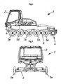
- Fig. 1 shows a schematic side view of a Pisteriprpparungsterrorismes 1 with a cab 2, which is arranged on a substantially rectangular chassis frame 3.
- On the chassis frame 3 is also on each side of the slope preparation vehicle 1 at least one drive wheel 4 arranged for a non-illustrated track, which is provided for driving the vehicle.
- support wheels 5a-5e are also provided, which serve to support the track.
- the illustration shown is merely exemplary in nature, it can be provided on each side of the slope preparation vehicle 1, a plurality of drive wheels 4, which are mounted movable limited by the described working position in a transport position or in the reverse direction.
- Fig. 2 shows a front view of the slope preparation vehicle 1 with the cab 2 and mounted on the chassis frame 3 carrying wheels 5e on both sides of the vehicle.
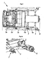
- Fig. 3 shows a schematic plan view of the slope preparation vehicle 1.
- the drive wheel 4 On the chassis frame 3, the drive wheel 4 is provided for the chain in addition to the load-transmitting support wheels 5a-5e
- the drive wheel 4 is mounted on the chassis frame 3 via a wheel bearing 6. In the figure shown, the drive wheel 4 is in the working position, ie in the position in which it is provided for the usual drive of the crawler during piste preparation.
- At least one drive wheel 4 or its wheel bearing 6 is so limited to the chassis frame 3 movable that the drive wheel 4 and the wheel bearing 6 is movable to a transport position, which is within the width B of the chassis frame 3, as in the following figures will be explained in more detail.
- Fig. 4a shows a front perspective view of the chassis frame 3 with disassembled drive wheel 4 and disassembled support wheel 5a, so that the wheel bearing 6 and the bearing part 7 for the support wheel 5a can be seen.
- the wheel bearing 6 is located in the figure shown in the working position in which it protrudes laterally with respect to the chassis frame 3.
- the bearing part 7 for the support wheel 5a has a releasable fastening device for releasably connecting to the chassis frame 3. During transport, the bearing parts 7 can be unscrewed in a simple manner from the chassis frame 3,
- Fig. 4b shows the illustration according to Fig. 4a in a perspective rear view. From this point of view, the flexible hydraulic hoses 8a and 8b can be seen, which are part of a hydraulic drive for the drive wheel 4. Evident is also a wedge-shaped fastening part 9, which serves to lock the relative position of the wheel bearing 6 in the working position and in the transport position.
- Fig. 5 now shows the pivoted into the transport position wheel bearing 6.
- the wedge-shaped fastening part 9 ( Fig. 4b ), whereupon the wheel bearing 6 is pivotable about at least one - preferably horizontal - axis 10.
- the Wheel bearing 6 is now within the width B ( Fig. 3 It can be seen that the two flexible hydraulic hoses 8a and 8b in the limited movement between the in Fig. 4b shown working position and the in Fig. 5 shown transport position constantly connected to the wheel bearing 6 remain. Thereby no time- and labor-intensive procedure of disassembly or retrofitting of the hydraulic hoses 8a and 8b are avoided.
- the in Fig. 4b shown unscrewable fastening part 9 is now screwed to lock the transport position at another location. Thus, one and the same fastening part 9 serves to lock both end positions.
- Fig. 6a and Fig. 6b show the corresponding comparison of the working position ( Fig. 6a ) and the transport position ( Fig. 6b ) in a rear view.
- the pivoting range of the wheel bearing 6 carried out in the course of this pivoting movement is preferably between 0 ° and 90 °. It is favorable, however, provided that the wheel bearing 6 is in the transport position in any case within the width of the chassis frame 3.
- Fig. 7a and Fig. 7b show the corresponding comparison of the working position ( Fig. 7a ) and the transport position ( Fig. 7b ) in a plan view.
- Fig. 7a the fastening part 9 can be seen, which locks the working position shown, while the fastening part 9 in Fig. 7b was mounted at a different location and thereby locks the transport position.
- the present invention is not limited to the illustrated embodiment, but includes all variants and technical equivalents, which may fall within the scope of the following claims.
- location information chosen in the description such as top, bottom, side, etc. relative to the usual installation position or on the immediately described and illustrated figure and are to be transferred to a new position analogous to a change in position.
- the adjusting means for the limited movement of the drive wheel 4 or its wheel bearing 6 between the working position and the transport position can of course also have at least one, preferably hydraulically operable, piston-cylinder unit.
Landscapes
- Engineering & Computer Science (AREA)
- Chemical & Material Sciences (AREA)
- Combustion & Propulsion (AREA)
- Transportation (AREA)
- Mechanical Engineering (AREA)
- Body Structure For Vehicles (AREA)
- Handcart (AREA)
- Agricultural Machines (AREA)
- Automobile Manufacture Line, Endless Track Vehicle, Trailer (AREA)
- Devices For Conveying Motion By Means Of Endless Flexible Members (AREA)
Description
- Die vorliegende Erfindung bezieht sich auf ein Pistenpräparationsfahrzeug mit einem Fahrwerkrahmen und wenigstens einem Antriebsrad für eine Laufkette.
- Bei Pistenpräparationsfahrzeugen werden zum Zweck einer optimierten Flächenleistung und aus Gründen der Zeiteffizienz immer häufiger Fahrzeuge mit größerer Spurbreite eingesetzt. Auf diese Weise können auch breitere Raupen, Räumschilder und Schneefräsen am Fahrzeug montiert werden, um damit kürzere Arbeitszeiten und verminderte Betriebsstunden des Fahrzeuges zu ermöglichen. Im Servicefall oder zur Überstellung der Fahrzeuge an einen anderen Ort müssen diese oftmals auf Lastkraftwagen zum anschließenden Transport auf die Strasse aufgeladen werden. Aufgrund der großen Breite dieser Pistenfahrzeuge ist es häufig notwendig, dass diese hierfür auf einem überbreiten Sondertransport befördert werden muss, was neben einem beträchtlichen Verkehrshindernis auch sehr kostenintensiv ist. Zudem sind diese Sondertransporte mittels LKW auf vielen Passstrassen und Nebenstrassen, die zu den Skigebieten führen, nicht zugelassen.
- Das Dokument
JP-07237566-A - Aufgabe der vorliegenden Erfindung ist es daher, ein Pistenpräparationsfahrzeug der eingangs erwähnten Gattung mit verbesserten Transporteigenschaften vorzuschlagen.
- Dies wird erfindungsgemäß in einer vorteilhaften Ausgestaltung dadurch erreicht, dass das Radlager des Antriebsrads am Fahrwerkrahmen um eine horizontale Achse schwenkbar gelagert ist.
- Auf diese Weise können die üblicherweise sehr massiv ausgeführten Antriebsräder - vorzugsweise auf beiden gegenüberliegenden Seiten des Pistenpräparationsfahrzeug - in eine innerhalb der Breite des Fahrzeugrahmens gelegene Position bewegt werden, sodass die Breite des zu transportierenden Fahrzeuges im Wesentlichen der maximalen Abmessung des Fahrzeugrahmens entspricht. Somit erreicht man eine Verringerung der effektiven Breite des Fahrzeuges, sodass ein Transport mittels LKW in verkehrstechnisch schwieriger zu erreichende Skigebiete überhaupt erst ermöglicht wird.
- Gemäß einem bevorzugten Ausführungsbeispiel der Erfindung ist vorgesehen, dass das Antriebsrad über ein Radlager am Fahrwerkrahmen gelagert ist.
- In diesem Zusammenhang kann es günstig sein, wenn das Radlager am Fahrwerkrahmen, vorzugsweise um eine horizontale Achse, schwenkbar gelagert ist. Dabei kann es vorteilhaft sein, wenn der Schwenkbereich zwischen 0° und 180°, vorzugsweise zwischen 0° und 90°, liegt.
- Gemäß einem weiteren Ausführungsbeispiel der Erfindung kann vorgesehen sein, dass das Radlager in der Arbeitsstellung und/oder in der Transportstellung relativ zum Fahrwerkrahmen durch Arretiermittel fixierbar ist. Dies ist insofern wichtig, dass das Radlager insbesondere beim Transport auf der Straße keine unkontrollierten Bewegungen auszuführen vermag, Aus diesem Grund ist die relative Lage des Radlagers in Bezug zum Fahrwerkrahmen in wenigstens einer der beiden Endlagen fixierbar.
- Gemäß einem weiteren Ausführungsbeispiel der Erfindung kann vorgesehen sein, dass das Antriebsrad mittels einem hydraulischen Antrieb antreibbar ist. Dabei kann es zweckmäßig sein, wenn der hydraulische Antrieb wenigstens eine Hydraulikleitung, vorzugsweise einen flexiblen Hydraulikschlauch, aufweist, die am Radlager angeordnet ist. Eine Besonderheit der gegenständlichen Erfindung liegt nunmehr darin, dass die Hydraulikleitung bei der begrenzten Bewegung zwischen der Arbeitsstellung und der Transportstellung ständig mit dem Radlager verbunden ist. Somit ist das Radlager zusammen mit den daran angeschlossenen flexiblen Hydraulikleitungen von der beschriebenen Arbeitsstellung in die Transportstellung bzw. in die umgekehrte Richtung bewegbar, ohne dass dabei die Notwendigkeit besteht, die Hydraulikleitungen zu demontieren bzw. darüber hinaus auch das Hydrauliköl abzulassen.
- Auf diese Weise kann der zeit- und arbeitsaufwendige Prozess der Demontage bzw. der Montage der Hydraulikleitungen vermieden werden. Da bei einem Pistenpräparationsfahrzeug neben den eigentlichen Antriebsrädern für die Laufkette auch mehrere Tragräder zur Abstützung der Laufkette vorgesehen sind, ist es zweckmäßig, wenn die Tragräder über Lagerteile am Fahrwerkrahmen gelagert sind. Eine vorteilhafte Ausführungsform der Erfindung ergibt sich dadurch, dass die Lagerteile am Fahrwerkrahmen lösbar befestigbar, vorzugsweise verschraubbar, angeordnet sind. Auf diese Weise existieren beim Transport keine vom Fahrwerkrahmen nach außen abstehenden Teile, die ein erhöhtes Unfallrisiko herbeiführen könnten.
- Weitere Einzelheiten der Erfindung werden anhand der nachstehenden Figurenbeschreibung erläutert. Darin zeigt bzw. zeigen:
- Fig. 1
- eine Seitenansicht eines Pistenpräparationsfahrzeuges,
- Fig. 2
- das Pistenpräparationsfahrzeug in einer Vorderansicht,
- Fig. 3
- das Pistenpräparationsfahrzeug in einer Draufsicht,
- Fig. 4a
- eine Detailansicht eines am Fahrwerkrahmen gelagerten Radlagers in der Arbeitsstellung in einer perspektivischen Vorderansicht,
- Fig. 4b
- das Radlager in der Arbeitsstellung in einer perspektivischen Hinteransicht,
- Fig. 5
- das verschwenkte Radlager in der Transportstellung in einer perspektivischen Hinteransicht,
- Fig. 6a
- eine Hinteransicht des Radlagers in der Arbeitsstellung,
- Fig. 6b
- eine Hinteransicht des Radlagers in der Transportstellung,
- Fig. 7a
- eine Draufsicht auf das Radlager in der Arbeitsstellung,
- Fig. 7b
- eine Draufsicht auf das Radlager in der Transportstellung.
-
Fig. 1 zeigt eine schematische Seitenansicht eines Pisteripräparationsfahrzeuges 1 mit einer Führerkabine 2, die auf einem im Wesentlichen rechteckförmigen Fahrwerkrahmen 3 angeordnet ist. Am Fahrwerkrahmen 3 ist zudem auf jeder Seite des Pistenpräparationsfahrzeuges 1 wenigstens ein Antriebsrad 4 für eine nicht näher dargestellte Laufkette angeordnet, die zum Antrieb des Fahrzeuges vorgesehen ist. Neben dem eigentlichen Antriebsrad 4 sind zudem Tragräder 5a-5e vorgesehen, die zur Abstützung der Laufkette dienen. Die gezeigte Darstellung ist lediglich beispielhafter Natur, es können auf jeder Seite des Pistenpräparationsfahrzeuges 1 auch mehrere Antriebsräder 4 vorgesehen sein, die von der beschriebenen Arbeitsstellung in eine Transportstellung bzw. in die umgekehrte Richtung begrenzt bewegbar gelagert sind. -
Fig. 2 zeigt eine Frontansicht des Pistenpräparationsfahrzeuges 1 mit der Führerkabine 2 und den auf dem Fahrwerkrahmen 3 gelagerten Tragrädern 5e auf beiden Seiten des Fahrzeuges. -
Fig. 3 zeigt eine schematische Draufsicht auf das Pistenpräparationsfahrzeug 1. Im Folgenden wird lediglich auf das untere Antriebsrad 4 sowie auf die Ausgestaltung der Tragräder 5a-5e - also auf die linke Seite des Fahrzeuges - Bezug genommen. Am Fahrwerkrahmen 3 ist neben den lastübertragenden Tragrädern 5a-5e das Antriebsrad 4 für die Laufkette vorgesehen Das Antriebsrad 4 ist über ein Radlager 6 am Fahrwerkrahmen 3 gelagert. In der gezeigten Figur befindet sich das Antriebsrad 4 in der Arbeitsstellung, d.h. in der Stellung, in der es zum üblichen Antrieb der Laufkette bei der Pistenpräparation vorgesehen ist. Gemäß der Erfindung ist auch wenigstens ein Antriebsrad 4 bzw. dessen Radlager 6 derart zum Fahrwerkrahmen 3 begrenzt bewegbar, dass das Antriebsrad 4 bzw. dessen Radlager 6 in eine Transportstellung bewegbar ist, die innerhalb der Breite B des Fahrwerkrahmens 3 liegt, so wie dies in den nachfolgenden Figuren noch näher erläutert wird. -
Fig. 4a zeigt eine perspektivische Vorderansicht des Fahrwerkrahmens 3 mit demontiertem Antriebsrad 4 und demontiertem Tragrad 5a, sodass das Radlager 6 und das Lagerteil 7 für das Tragrad 5a ersichtlich ist. Das Radlager 6 befindet sich in der gezeigten Figur in der Arbeitsstellung, in der es in Bezug zum Fahrwerkrahmen 3 seitlich absteht. Das Lagerteil 7 für das Tragrad 5a weist eine lösbare Befestigungsvorrichtung zum lösbaren Verbinden mit dem Fahrwerkrahmen 3 auf. Beim Transport können die Lagerteile 7 in einfacher Weise vom Fahrwerkrahmen 3 abgeschraubt werden, -
Fig. 4b zeigt die Darstellung gemäßFig. 4a in einer perspektivischen Hinteransicht. Aus diesem Blickwinkel sind die flexiblen Hydraulikschläuche 8a und 8b ersichtlich, die Teil eines hydraulischen Antriebes für das Antriebsrad 4 sind. Zu erkennen ist zudem ein keilförmiger Befestigungsteil 9, der zum Arretieren der relativen Lage des Radlagers 6 in der Arbeitsstellung als auch in der Transportstellung dient. -
Fig. 5 zeigt nun das in die Transportstellung verschwenkte Radlager 6. Hierfür wurde der keilförmige Befestigungsteil 9 (Fig. 4b ) abgeschraubt, woraufhin das Radlager 6 um wenigstens eine - vorzugsweise horizontale - Achse 10 verschwenkbar ist. Das Radlager 6 liegt nun innerhalb der Breite B (Fig. 3 ) des Fahrzeugrahmens 3. Zu erkennen ist, dass die beiden flexiblen Hydraulikschläuche 8a und 8b bei der begrenzten Bewegung zwischen der inFig. 4b gezeigten Arbeitsstellung und der inFig. 5 gezeigten Transportstellung ständig mit dem Radlager 6 verbunden bleiben. Dadurch keine eine zeit- und arbeitsintensive Prozedur der Demontage bzw. der nachträglichen Montage der Hydraulikschläuche 8a und 8b vermieden werden. Der inFig. 4b dargestellte abschraubbare Befestigungsteil 9 wird nun zum Arretieren der Transportstellung an einer anderen Stelle angeschraubt. Somit dient ein und derselbe Befestigungsteil 9 zum Arretieren beider Endlagen. -
Fig. 6a und Fig. 6b zeigen die entsprechende Gegenüberstellung der Arbeitsstellung (Fig. 6a ) und der Transportstellung (Fig. 6b ) in einer Hinteransicht. Der im Zuge dieser Verschwenkbewegung durchgeführte Schwenkbereich des Radlagers 6 liegt vorzugsweise zwischen 0° und 90°. Günstig ist jedoch vorgesehen, dass das Radlager 6 in der Transportstellung auf jeden Fall innerhalb der Breite des Fahrwerkrahmens 3 liegt. -
Fig. 7a und Fig. 7b zeigen die entsprechende Gegenüberstellung der Arbeitsstellung (Fig. 7a ) und der Transportstellung (Fig. 7b ) in einer Draufsicht. InFig. 7a ist der Befestigungsteil 9 erkennbar, der die gezeigte Arbeitsstellung arretiert, während der Befestigungsteil 9 inFig. 7b an einer anderen Stelle montiert wurde und dabei die Transportstellung arretiert. - Die vorliegende Erfindung beschränkt sich nicht auf das dargestellte Ausführungsbeispiel, sondern umfasst bzw. erstreckt sich auf alle Varianten und technischen Äquivalente, welche in die Reichweite der nachfolgenden Ansprüche fallen können. Auch sind die in der Beschreibung gewählten Lageangaben, wie z.B. oben, unten, seitlich usw. auf die übliche Einbaulage bzw. auf die unmittelbar beschriebene sowie dargestellte Figur bezogen und sind-bei einer Lageänderung sinngemäß auf die neue Lage zu übertragen. Die Verstellmittel zur begrenzten Bewegung des Antriebsrades 4 bzw. dessen Radlagers 6 zwischen der Arbeitsstellung und der Transportstellung können selbstverständlich auch wenigstens eine, vorzugsweise hydraulisch betreibbare, Kolben-Zylinder-Einheit aufweisen.
Claims (10)
- Pistenpräparationsfahrzeug mit einem Fahzwerkrahmen (3) und wenigstens einem Antriebsrad (4) für eine Laufkette, wobei das Antriebsrad (4) zwischen einer Arbeitsstellung - in der das Antriebsrad (4) über den Fahrwerkrahmen (3) vorsteht - und einer Transportstellung - in der das Antriebsrad (4) zumindest bereichsweise, vorzugsweise vollständig, innerhalb der Breite (B) des Fahrwerkrahmens (3) liegt - begrenzt bewegbar ist, wobei das Antriebsrad (4) über ein Radlager (6) am Fahrwerkrahmen (3) gelagert ist; dadurch gekennzeichnet, dass das Radlager (6) am Fahrwerkrahmen (3) um eine horizontale Achse (10) schwenkbar gelagert ist.
- Pistenpräparationsfahrzeug nach Anspruch 1, dadurch gekennzeichnet, dass das Radlager (6) in der Arbeitsstellung und oder in der Transportstellung relativ zum Fahrwerkrahmen (3) durch Arretiermittel fixierbar ist.
- Pistenpräparationsfahrzeug nach Anspruch 2, dadurch gekennzeichnet, dass die Arretiermittel wenigstens einen Befestigungsteil (9) aufweisen, der einerseits am Fahrwerkrahmen (3) und andererseits am Radlager (6) lösbar befestigbar, vorzugsweise verschraubbar, ist.
- Pistenpräparationsfahrzeug nach Anspruch 3, dadurch gekennzeichnet, dass ein und derselbe Befestigungsteil (9) zum Arretieren der Arbeitsstellung und der Transportstellung vorgesehen ist.
- Pistenpräparationsfahrzeug nach einem der Ansprüche 1 bis 4, dadurch gekennzeichnet, dass das Antriebsrad (4) mittels einem hydraulischen Antrieb antreibbar ist.
- Pistenpräparationsfahrzeug nach Anspruch 5, dadurch gekennzeichnet, dass der hydraulische Antrieb wenigstens eine Hydraulikleitung (8a, 8b), vorzugsweise einen flexiblen Hydraulikschlauch, aufweist, die am Radlager (6) angeordnet ist.
- Pistenpräparationsfahrzeug nach Anspruch 6, dadurch gekennzeichnet, dass die Hydraulikleitung (8a, 8b) bei der begrenzten Bewegung zwischen der Arbeitsstellung und der Transportstellung ständig mit dem Radlager (6) verbunden ist.
- Pistenpräparationsfahrzeug nach einem der Ansprüche 1, bis 7, dadurch gekennzeichnet, dass - vorzugsweise mehrere - Tragräder (5a-5e) für die Laufkette vorgesehen sind.
- Pistenpräparationsfahrzeug nach Anspruch 8, dadurch gekennzeichnet, dass die Tragräder (5a-5e) über Lagerteile (7) am Fabrwerkrahmen (3) gelagert sind.
- Pistenpräparationsfahrzeug nach Anspruch 9, dadurch gekennzeichnet, dass die Lagerteile (7) am Fahrwerkrahmen (3) lösbar befeshgbar, vorzugsweise verschraubbar, angeordnet sind.
Priority Applications (5)
| Application Number | Priority Date | Filing Date | Title |
|---|---|---|---|
| EP06020982A EP1908673B1 (de) | 2006-10-06 | 2006-10-06 | Raupenfahrzeug |
| DE502006005598T DE502006005598D1 (de) | 2006-10-06 | 2006-10-06 | Raupenfahrzeug |
| AT06020982T ATE451290T1 (de) | 2006-10-06 | 2006-10-06 | Raupenfahrzeug |
| CA2606299A CA2606299C (en) | 2006-10-06 | 2007-10-05 | Tracked vehicle |
| US11/868,322 US8353372B2 (en) | 2006-10-06 | 2007-10-05 | Tracked vehicle |
Applications Claiming Priority (1)
| Application Number | Priority Date | Filing Date | Title |
|---|---|---|---|
| EP06020982A EP1908673B1 (de) | 2006-10-06 | 2006-10-06 | Raupenfahrzeug |
Publications (2)
| Publication Number | Publication Date |
|---|---|
| EP1908673A1 EP1908673A1 (de) | 2008-04-09 |
| EP1908673B1 true EP1908673B1 (de) | 2009-12-09 |
Family
ID=37776453
Family Applications (1)
| Application Number | Title | Priority Date | Filing Date |
|---|---|---|---|
| EP06020982A Not-in-force EP1908673B1 (de) | 2006-10-06 | 2006-10-06 | Raupenfahrzeug |
Country Status (5)
| Country | Link |
|---|---|
| US (1) | US8353372B2 (de) |
| EP (1) | EP1908673B1 (de) |
| AT (1) | ATE451290T1 (de) |
| CA (1) | CA2606299C (de) |
| DE (1) | DE502006005598D1 (de) |
Cited By (8)
| Publication number | Priority date | Publication date | Assignee | Title |
|---|---|---|---|---|
| USD630551S1 (en) | 2009-10-23 | 2011-01-11 | Rolic Invest S.Ar.L. | Snow groomer |
| US8307573B2 (en) | 2007-10-31 | 2012-11-13 | Rolic Invest S.A.R.L. | Rotary snow tiller for grooming ski slopes |
| US8387288B2 (en) | 2007-10-31 | 2013-03-05 | Rolic Invest S.Ar.L. | Rotary snow tiller for grooming ski slopes |
| US8388072B2 (en) | 2007-06-21 | 2013-03-05 | Rolic Invest S.Ar.L. | Crawler vehicle track grouser |
| US8393095B2 (en) | 2007-10-30 | 2013-03-12 | Rolic Invest S.AR. L. | Rotary snow tiller and ski slope grooming method |
| US8413353B2 (en) | 2007-10-30 | 2013-04-09 | Rolic Invest S.Ar.L. | Hitch device for connecting a groomer vehicle and a ski slope snow grooming implement, and control method employing such a hitch device |
| US8757736B2 (en) | 2008-05-29 | 2014-06-24 | Snowgrolic S. AR. L. | Snow groomer track and snow groomer featuring such a track |
| US8839533B2 (en) | 2009-02-18 | 2014-09-23 | Snowgrolic S.A.R.L. | Snowgroomer including a winch assembly to aid handling of the snowgroomer on steep slopes, and method of operating the winch assembly |
Families Citing this family (10)
| Publication number | Priority date | Publication date | Assignee | Title |
|---|---|---|---|---|
| ATE463412T1 (de) * | 2006-10-06 | 2010-04-15 | Rolic Invest Sarl | Raupenfahrzeug |
| ITMI20070188U1 (it) * | 2007-05-25 | 2008-11-26 | Rolic Invest Sarl | Veicolo battipista |
| DE102008059467A1 (de) * | 2008-11-28 | 2010-06-10 | Claas Selbstfahrende Erntemaschinen Gmbh | Landwirtschaftliche Zugmaschine |
| DE102012203905A1 (de) * | 2012-03-13 | 2013-09-19 | Kässbohrer Geländefahrzeug AG | Pistenraupe zur Schneeflächenbearbeitung |
| DE102014001006A1 (de) * | 2014-01-29 | 2015-07-30 | Hans Hall Gmbh | Traktionskette für eine Raupenkette eines Kettenfahrzeugs sowie Bausatz für eine Raupenkette |
| USD845353S1 (en) | 2016-04-11 | 2019-04-09 | Prinoth S.P.A. | Snow groomer |
| PL3565741T3 (pl) | 2017-01-05 | 2022-04-11 | Revivermx, Inc. | System kontroli ciepła do cyfrowej tablicy rejestracyjnej |
| WO2018129371A1 (en) | 2017-01-05 | 2018-07-12 | Revivermx, Inc. | Digital license plate system with antitheft system |
| WO2018129343A1 (en) | 2017-01-05 | 2018-07-12 | Revivermx, Inc. | Power and communication modes for digital license plate |
| US11731715B2 (en) | 2018-02-15 | 2023-08-22 | Soucy International Inc. | Track assembly and vehicle |
Family Cites Families (49)
| Publication number | Priority date | Publication date | Assignee | Title |
|---|---|---|---|---|
| US3170533A (en) | 1963-07-05 | 1965-02-23 | Ling Temco Vought Inc | Vehicle with pneumatic support |
| US3227295A (en) | 1964-12-09 | 1966-01-04 | Douglas D Hamilton | Self-loading full tree skidding vehicle |
| US3534701A (en) | 1968-09-27 | 1970-10-20 | Nanuk Inc | Amphibious snow vehicle |
| US3763944A (en) | 1971-02-26 | 1973-10-09 | B Kaltenegger | Steering transmission mechanism and vehicles with rigidly mounted axles incorporating said mechanism |
| DE2145772A1 (de) | 1971-09-14 | 1973-03-22 | Fendt & Co Xaver | Walze fuer schneepistengeraete |
| DE2148304A1 (de) | 1971-09-28 | 1973-04-05 | Henry Neuenburg | Fraeswalze |
| DE2219623A1 (de) | 1972-04-21 | 1973-11-08 | Fendt & Co Xaver | Pistenraupe |
| DE2254276A1 (de) | 1972-11-06 | 1974-05-22 | Kaessbohrer Fahrzeug Karl | Gleiskettenfahrzeug |
| FR2336292A1 (fr) | 1975-12-23 | 1977-07-22 | Martin Rene | Vehicule chenille perfectionne |
| US4087135A (en) * | 1976-09-17 | 1978-05-02 | Caterpillar Tractor Co. | Excavator idler-outrigger |
| GB1590358A (en) | 1977-08-26 | 1981-06-03 | Caterpillar Tractor Co | Apex track shoe |
| AT375557B (de) | 1979-07-13 | 1984-08-27 | Baechler Anton R | Spur- und/oder planiergeraet fuer ski-loipen bzw. pisten |
| IT8223514U1 (it) | 1982-11-22 | 1984-05-22 | Leitner Spa | Fresaneve a tamburo rotante per piste da sci. |
| US4500139A (en) * | 1983-01-28 | 1985-02-19 | J. I. Case Company | Crawler track support system with vertically extensible centra rollers |
| DE3440491C2 (de) | 1984-11-06 | 1987-03-12 | Martin Beilhack Maschinenfabrik Und Hammerwerk Gmbh, 8200 Rosenheim | Schneepflug |
| FR2577357B1 (fr) | 1985-02-11 | 1988-07-15 | Labavia | Perfectionnements aux ralentisseurs electriques |
| DE3534626A1 (de) * | 1985-09-04 | 1987-03-12 | Schaeff Karl Gmbh & Co | Hydraulikbagger mit verstellbarem raupenlaufwerk |
| US4788783A (en) | 1987-03-24 | 1988-12-06 | Bachler Anton R | Ski-track forming apparatus |
| JPH01144287A (ja) | 1987-11-30 | 1989-06-06 | Mitsubishi Electric Corp | データ記憶装置 |
| IT1234428B (it) * | 1989-07-24 | 1992-05-18 | Leitner Spa | Veicolo cingolato, in particolare per la preparazione di piste da sci |
| CA2008235C (en) * | 1990-01-22 | 1999-08-31 | Michel Pelletier | Variable geometry tiller |
| IT1260303B (it) | 1992-01-10 | 1996-04-05 | Leitner Spa | Portattrezzi portato da un veicolo semovente, in particolare per la preparazione di piste di sci |
| JPH07237566A (ja) * | 1993-07-20 | 1995-09-12 | Yua Tec:Kk | 無限軌道車 |
| DE29515866U1 (de) | 1995-10-06 | 1995-11-23 | Kleber, Adelhard, 66663 Merzig | Motorangetriebenes, auf Ketten laufendes Fahrzeug |
| DE29603251U1 (de) | 1996-02-23 | 1996-04-11 | Jäger, Arnold, 31303 Burgdorf | Laufband für Raupenfahrzeuge, insbesondere Schneefahrzeuge |
| US5975226A (en) | 1996-07-30 | 1999-11-02 | Honda Giken Kogyo Kabushiki Kaisha | Crawler belt vehicle |
| CA2256172A1 (en) | 1998-12-15 | 2000-06-15 | Bombardier Inc. | Multifunction joystick |
| IT1313729B1 (it) | 1999-09-15 | 2002-09-17 | Leitner Spa | Gruppo di fresatura per la battitura di piste innevate |
| WO2001044582A1 (en) * | 1999-12-17 | 2001-06-21 | Bombardier Inc. | Snow groomer having an improved variable geometry tiller assembly |
| ITBZ20010017A1 (it) | 2001-03-30 | 2002-09-30 | Leitner Snow Gmbh S R L | Macchina per la preparazione delle piste di neve con fresa girevolmente montata. |
| US20030159840A1 (en) | 2002-02-28 | 2003-08-28 | Anthony Schmidt | Power groomer for snow & earth terrain |
| FI117167B (sv) | 2002-10-01 | 2006-07-14 | Hydrolink Oy Ab | Styranordning |
| CA2441650C (en) | 2002-10-08 | 2008-12-02 | Bombardier Recreational Products | Level wind apparatus for use on a snow grooming vehicle |
| US20040083627A1 (en) | 2002-10-22 | 2004-05-06 | Bombardier Inc. | Snow groomer plow assembly |
| DE10320523A1 (de) | 2003-05-02 | 2004-11-18 | Kässbohrer Geländefahrzeug AG | Kettenlaufwerk und Laufkette für ein Kettenfahrzeug |
| US6921304B2 (en) * | 2003-06-18 | 2005-07-26 | Stanley C. Hewitt | Amphibious vehicle |
| DE10332936A1 (de) | 2003-07-19 | 2005-02-10 | Daimlerchrysler Ag | Steuerung einer elektrisch beheizten Vorwärmeinrichtung für den Kaltstart von Verbrennungsmotoren |
| NZ532006A (en) | 2004-03-29 | 2006-11-30 | Rodney Warwick Sharp | Tooth tip, typically for wood hogging apparatus, with tapered bottom face configured to interact with complementary base portion top face |
| EP1591350A3 (de) | 2004-04-27 | 2006-08-09 | Intertractor GmbH | Gleiskette für Kettenfahrzeuge |
| US7296862B2 (en) * | 2004-05-12 | 2007-11-20 | Clark Equipment Company | Collapsible track undercarriage for installation and tensioning |
| AT502564B1 (de) | 2004-06-04 | 2008-06-15 | Prinoth S R L | Pistenpräparationsfahrzeug mit einer seilwinde |
| EP1674382A1 (de) | 2004-12-22 | 2006-06-28 | Prinoth A.G. | Kettensteg für Laufketten |
| AT501048B8 (de) | 2004-12-22 | 2007-02-15 | Prinoth A G | Kettensteg für eine laufkette von raupenfahrzeugen, insbesondere pistenfahrzeuge oder loipenspurgeräte |
| WO2006069682A1 (de) | 2004-12-22 | 2006-07-06 | Prinoth Ag | Kettensteg für eine laufkette von raupenfahrzeugen, insbesondere pistenfahrzeuge oder loipenspurgeräte |
| SE528322C2 (sv) * | 2005-09-08 | 2006-10-17 | Aake Olsson | Banddrivet fordon, speciellt en snöskoter, innefattande två främre drivbandsaggregat |
| SE529218C2 (sv) | 2005-10-26 | 2007-06-05 | Volvo Lastvagnar Ab | System och förfarande för reglering av axellastfördelningsförhållandet på ett fordon med två framaxlar |
| US7328529B2 (en) * | 2006-01-03 | 2008-02-12 | The Toro Company | Mower convertible into a tracked implement and vice versa |
| FR2902810B1 (fr) | 2006-06-27 | 2011-10-28 | Cochet Sa | Systeme de balayage a efficacite longue duree. |
| ATE463412T1 (de) | 2006-10-06 | 2010-04-15 | Rolic Invest Sarl | Raupenfahrzeug |
-
2006
- 2006-10-06 AT AT06020982T patent/ATE451290T1/de active
- 2006-10-06 DE DE502006005598T patent/DE502006005598D1/de active Active
- 2006-10-06 EP EP06020982A patent/EP1908673B1/de not_active Not-in-force
-
2007
- 2007-10-05 US US11/868,322 patent/US8353372B2/en not_active Expired - Fee Related
- 2007-10-05 CA CA2606299A patent/CA2606299C/en not_active Expired - Fee Related
Cited By (9)
| Publication number | Priority date | Publication date | Assignee | Title |
|---|---|---|---|---|
| US8388072B2 (en) | 2007-06-21 | 2013-03-05 | Rolic Invest S.Ar.L. | Crawler vehicle track grouser |
| US8393095B2 (en) | 2007-10-30 | 2013-03-12 | Rolic Invest S.AR. L. | Rotary snow tiller and ski slope grooming method |
| US8413353B2 (en) | 2007-10-30 | 2013-04-09 | Rolic Invest S.Ar.L. | Hitch device for connecting a groomer vehicle and a ski slope snow grooming implement, and control method employing such a hitch device |
| US8701312B2 (en) | 2007-10-30 | 2014-04-22 | Snowgrolic S.Ar.L. | Hitch device for connecting a groomer vehicle and a ski slope snow grooming implement, and control method employing such a hitch device |
| US8307573B2 (en) | 2007-10-31 | 2012-11-13 | Rolic Invest S.A.R.L. | Rotary snow tiller for grooming ski slopes |
| US8387288B2 (en) | 2007-10-31 | 2013-03-05 | Rolic Invest S.Ar.L. | Rotary snow tiller for grooming ski slopes |
| US8757736B2 (en) | 2008-05-29 | 2014-06-24 | Snowgrolic S. AR. L. | Snow groomer track and snow groomer featuring such a track |
| US8839533B2 (en) | 2009-02-18 | 2014-09-23 | Snowgrolic S.A.R.L. | Snowgroomer including a winch assembly to aid handling of the snowgroomer on steep slopes, and method of operating the winch assembly |
| USD630551S1 (en) | 2009-10-23 | 2011-01-11 | Rolic Invest S.Ar.L. | Snow groomer |
Also Published As
| Publication number | Publication date |
|---|---|
| CA2606299C (en) | 2014-12-09 |
| US8353372B2 (en) | 2013-01-15 |
| CA2606299A1 (en) | 2008-04-06 |
| DE502006005598D1 (de) | 2010-01-21 |
| EP1908673A1 (de) | 2008-04-09 |
| US20090000833A1 (en) | 2009-01-01 |
| ATE451290T1 (de) | 2009-12-15 |
Similar Documents
| Publication | Publication Date | Title |
|---|---|---|
| EP1908673B1 (de) | Raupenfahrzeug | |
| AT396097B (de) | Chassis fuer raupenfahrwerke | |
| DE60309697T2 (de) | Sowohl auf strassen als auch auf eisenbahnschienen fahrbares fahrzeug | |
| DE1944214A1 (de) | Drehkran-Fahrgestell | |
| EP0271645A1 (de) | Schneepflug | |
| DE60131455T2 (de) | Reifenketten mit geringem bodendruck für kompaktlader und andere baumaschinen | |
| EP1522634A2 (de) | Hecklader-Strassenfrässmaschine mit höhenverstellbarer Abdichtungseinrichtung | |
| DE3016232A1 (de) | Selbstfahrende betonpumpe | |
| EP2013041B1 (de) | Transportgerät | |
| DE1932243A1 (de) | Lenkeinrichtung fuer Anhaenger | |
| DE3108614A1 (de) | Vorrichtung zum maehen von gras insbesondere unter absperrungen | |
| DE102007042599A1 (de) | Trägerfahrzeug | |
| EP3143861B2 (de) | Landwirtschaftliches mähwerk und zuggespann und verfahren zum betreiben des mähwerks | |
| DE102005003739B3 (de) | Baumaschine, sowie Schwenkeinrichtung | |
| DE10116578A1 (de) | Baufahrzeug mit einem Arbeitsgerät | |
| EP0762999B1 (de) | Verfahrbare vorrichtung zur durcharbeitung und/oder umsetzung von anhäufungen von materialien (mieten) und dafür vorzugsweise vorgesehene räumeinrichtung | |
| DE202010009744U1 (de) | Raupen- oder Kettenlaufwerk sowie selbstfahrende Arbeitsmaschine mit einem solchen Laufwerk | |
| DE102015006940A1 (de) | Reinigungsvorrichtung für Reifen oder Gleisketten eines Fahrzeugs | |
| DE202022105506U1 (de) | Fahrwerk für Zweiwegefahrzeug | |
| DE202011102504U1 (de) | Selbstfahrende Arbeitsmaschine mit einem Kettenlaufwerk | |
| DE19822809C2 (de) | Knickrahmengelenktes Ladefahrzeug | |
| DE69608589T2 (de) | Vorrichtung zum Festhalten einer Brücke auf einem Transportfahrzeug | |
| DE2216307A1 (de) | Spurbreitenveraenderbares gleiskettenfahrzeug | |
| EP0097165A1 (de) | Anhänger für einen lastkraftwagen. | |
| EP1318068B1 (de) | Raupenfahrzeug mit geteiltem Raupenträger und Verfahren zur Montage und Demontage eines Raupenträgers |
Legal Events
| Date | Code | Title | Description |
|---|---|---|---|
| PUAI | Public reference made under article 153(3) epc to a published international application that has entered the european phase |
Free format text: ORIGINAL CODE: 0009012 |
|
| AK | Designated contracting states |
Kind code of ref document: A1 Designated state(s): AT BE BG CH CY CZ DE DK EE ES FI FR GB GR HU IE IS IT LI LT LU LV MC NL PL PT RO SE SI SK TR |
|
| AX | Request for extension of the european patent |
Extension state: AL BA HR MK RS |
|
| RAP1 | Party data changed (applicant data changed or rights of an application transferred) |
Owner name: ROLIC INVEST SARL |
|
| 17P | Request for examination filed |
Effective date: 20081008 |
|
| 17Q | First examination report despatched |
Effective date: 20081106 |
|
| AKX | Designation fees paid |
Designated state(s): AT BE BG CH CY CZ DE DK EE ES FI FR GB GR HU IE IS IT LI LT LU LV MC NL PL PT RO SE SI SK TR |
|
| GRAP | Despatch of communication of intention to grant a patent |
Free format text: ORIGINAL CODE: EPIDOSNIGR1 |
|
| GRAS | Grant fee paid |
Free format text: ORIGINAL CODE: EPIDOSNIGR3 |
|
| RIN1 | Information on inventor provided before grant (corrected) |
Inventor name: PELLETIER, MICHEL Inventor name: RUNGGALDIER, MARTIN Inventor name: SEBASTIEN, DORAIS |
|
| GRAA | (expected) grant |
Free format text: ORIGINAL CODE: 0009210 |
|
| AK | Designated contracting states |
Kind code of ref document: B1 Designated state(s): AT BE BG CH CY CZ DE DK EE ES FI FR GB GR HU IE IS IT LI LT LU LV MC NL PL PT RO SE SI SK TR |
|
| REG | Reference to a national code |
Ref country code: GB Ref legal event code: FG4D Free format text: NOT ENGLISH |
|
| REG | Reference to a national code |
Ref country code: CH Ref legal event code: EP |
|
| REG | Reference to a national code |
Ref country code: IE Ref legal event code: FG4D |
|
| REF | Corresponds to: |
Ref document number: 502006005598 Country of ref document: DE Date of ref document: 20100121 Kind code of ref document: P |
|
| REG | Reference to a national code |
Ref country code: CH Ref legal event code: NV Representative=s name: MOINAS & SAVOYE SA |
|
| RAP2 | Party data changed (patent owner data changed or rights of a patent transferred) |
Owner name: ROLIC INVEST SARL |
|
| REG | Reference to a national code |
Ref country code: NL Ref legal event code: VDEP Effective date: 20091209 |
|
| PG25 | Lapsed in a contracting state [announced via postgrant information from national office to epo] |
Ref country code: SE Free format text: LAPSE BECAUSE OF FAILURE TO SUBMIT A TRANSLATION OF THE DESCRIPTION OR TO PAY THE FEE WITHIN THE PRESCRIBED TIME-LIMIT Effective date: 20091209 Ref country code: LT Free format text: LAPSE BECAUSE OF FAILURE TO SUBMIT A TRANSLATION OF THE DESCRIPTION OR TO PAY THE FEE WITHIN THE PRESCRIBED TIME-LIMIT Effective date: 20091209 Ref country code: FI Free format text: LAPSE BECAUSE OF FAILURE TO SUBMIT A TRANSLATION OF THE DESCRIPTION OR TO PAY THE FEE WITHIN THE PRESCRIBED TIME-LIMIT Effective date: 20091209 |
|
| LTIE | Lt: invalidation of european patent or patent extension |
Effective date: 20091209 |
|
| PG25 | Lapsed in a contracting state [announced via postgrant information from national office to epo] |
Ref country code: SI Free format text: LAPSE BECAUSE OF FAILURE TO SUBMIT A TRANSLATION OF THE DESCRIPTION OR TO PAY THE FEE WITHIN THE PRESCRIBED TIME-LIMIT Effective date: 20091209 Ref country code: LV Free format text: LAPSE BECAUSE OF FAILURE TO SUBMIT A TRANSLATION OF THE DESCRIPTION OR TO PAY THE FEE WITHIN THE PRESCRIBED TIME-LIMIT Effective date: 20091209 Ref country code: PL Free format text: LAPSE BECAUSE OF FAILURE TO SUBMIT A TRANSLATION OF THE DESCRIPTION OR TO PAY THE FEE WITHIN THE PRESCRIBED TIME-LIMIT Effective date: 20091209 |
|
| REG | Reference to a national code |
Ref country code: IE Ref legal event code: FD4D |
|
| PG25 | Lapsed in a contracting state [announced via postgrant information from national office to epo] |
Ref country code: RO Free format text: LAPSE BECAUSE OF FAILURE TO SUBMIT A TRANSLATION OF THE DESCRIPTION OR TO PAY THE FEE WITHIN THE PRESCRIBED TIME-LIMIT Effective date: 20091209 Ref country code: NL Free format text: LAPSE BECAUSE OF FAILURE TO SUBMIT A TRANSLATION OF THE DESCRIPTION OR TO PAY THE FEE WITHIN THE PRESCRIBED TIME-LIMIT Effective date: 20091209 Ref country code: PT Free format text: LAPSE BECAUSE OF FAILURE TO SUBMIT A TRANSLATION OF THE DESCRIPTION OR TO PAY THE FEE WITHIN THE PRESCRIBED TIME-LIMIT Effective date: 20100409 Ref country code: BG Free format text: LAPSE BECAUSE OF FAILURE TO SUBMIT A TRANSLATION OF THE DESCRIPTION OR TO PAY THE FEE WITHIN THE PRESCRIBED TIME-LIMIT Effective date: 20100309 Ref country code: EE Free format text: LAPSE BECAUSE OF FAILURE TO SUBMIT A TRANSLATION OF THE DESCRIPTION OR TO PAY THE FEE WITHIN THE PRESCRIBED TIME-LIMIT Effective date: 20091209 Ref country code: IE Free format text: LAPSE BECAUSE OF FAILURE TO SUBMIT A TRANSLATION OF THE DESCRIPTION OR TO PAY THE FEE WITHIN THE PRESCRIBED TIME-LIMIT Effective date: 20091209 Ref country code: ES Free format text: LAPSE BECAUSE OF FAILURE TO SUBMIT A TRANSLATION OF THE DESCRIPTION OR TO PAY THE FEE WITHIN THE PRESCRIBED TIME-LIMIT Effective date: 20100320 Ref country code: IS Free format text: LAPSE BECAUSE OF FAILURE TO SUBMIT A TRANSLATION OF THE DESCRIPTION OR TO PAY THE FEE WITHIN THE PRESCRIBED TIME-LIMIT Effective date: 20100409 |
|
| PG25 | Lapsed in a contracting state [announced via postgrant information from national office to epo] |
Ref country code: SK Free format text: LAPSE BECAUSE OF FAILURE TO SUBMIT A TRANSLATION OF THE DESCRIPTION OR TO PAY THE FEE WITHIN THE PRESCRIBED TIME-LIMIT Effective date: 20091209 Ref country code: CZ Free format text: LAPSE BECAUSE OF FAILURE TO SUBMIT A TRANSLATION OF THE DESCRIPTION OR TO PAY THE FEE WITHIN THE PRESCRIBED TIME-LIMIT Effective date: 20091209 |
|
| PLBE | No opposition filed within time limit |
Free format text: ORIGINAL CODE: 0009261 |
|
| STAA | Information on the status of an ep patent application or granted ep patent |
Free format text: STATUS: NO OPPOSITION FILED WITHIN TIME LIMIT |
|
| PG25 | Lapsed in a contracting state [announced via postgrant information from national office to epo] |
Ref country code: CY Free format text: LAPSE BECAUSE OF FAILURE TO SUBMIT A TRANSLATION OF THE DESCRIPTION OR TO PAY THE FEE WITHIN THE PRESCRIBED TIME-LIMIT Effective date: 20091209 Ref country code: GR Free format text: LAPSE BECAUSE OF FAILURE TO SUBMIT A TRANSLATION OF THE DESCRIPTION OR TO PAY THE FEE WITHIN THE PRESCRIBED TIME-LIMIT Effective date: 20100310 |
|
| 26N | No opposition filed |
Effective date: 20100910 |
|
| PG25 | Lapsed in a contracting state [announced via postgrant information from national office to epo] |
Ref country code: DK Free format text: LAPSE BECAUSE OF FAILURE TO SUBMIT A TRANSLATION OF THE DESCRIPTION OR TO PAY THE FEE WITHIN THE PRESCRIBED TIME-LIMIT Effective date: 20091209 |
|
| BERE | Be: lapsed |
Owner name: ROLIC INVEST SARL Effective date: 20101031 |
|
| PG25 | Lapsed in a contracting state [announced via postgrant information from national office to epo] |
Ref country code: MC Free format text: LAPSE BECAUSE OF NON-PAYMENT OF DUE FEES Effective date: 20101031 |
|
| GBPC | Gb: european patent ceased through non-payment of renewal fee |
Effective date: 20101006 |
|
| PG25 | Lapsed in a contracting state [announced via postgrant information from national office to epo] |
Ref country code: BE Free format text: LAPSE BECAUSE OF NON-PAYMENT OF DUE FEES Effective date: 20101031 Ref country code: GB Free format text: LAPSE BECAUSE OF NON-PAYMENT OF DUE FEES Effective date: 20101006 |
|
| PG25 | Lapsed in a contracting state [announced via postgrant information from national office to epo] |
Ref country code: LU Free format text: LAPSE BECAUSE OF NON-PAYMENT OF DUE FEES Effective date: 20101006 Ref country code: HU Free format text: LAPSE BECAUSE OF FAILURE TO SUBMIT A TRANSLATION OF THE DESCRIPTION OR TO PAY THE FEE WITHIN THE PRESCRIBED TIME-LIMIT Effective date: 20100610 |
|
| PG25 | Lapsed in a contracting state [announced via postgrant information from national office to epo] |
Ref country code: TR Free format text: LAPSE BECAUSE OF FAILURE TO SUBMIT A TRANSLATION OF THE DESCRIPTION OR TO PAY THE FEE WITHIN THE PRESCRIBED TIME-LIMIT Effective date: 20091209 |
|
| REG | Reference to a national code |
Ref country code: FR Ref legal event code: TP Owner name: SNOWGROLIC S.A.R.L., LU Effective date: 20130711 |
|
| REG | Reference to a national code |
Ref country code: DE Ref legal event code: R082 Ref document number: 502006005598 Country of ref document: DE Representative=s name: HANSMANN & VOGESER, DE |
|
| REG | Reference to a national code |
Ref country code: CH Ref legal event code: PUE Owner name: SNOWGROLIC S.A R.L., LU Free format text: FORMER OWNER: ROLIC INVEST SARL, LU |
|
| REG | Reference to a national code |
Ref country code: DE Ref legal event code: R082 Ref document number: 502006005598 Country of ref document: DE Representative=s name: HANSMANN & VOGESER, DE Effective date: 20130828 Ref country code: DE Ref legal event code: R081 Ref document number: 502006005598 Country of ref document: DE Owner name: SNOWGROLIC S.A R.L., LU Free format text: FORMER OWNER: ROLIC INVEST SARL, LUXEMBURG, LU Effective date: 20130828 Ref country code: DE Ref legal event code: R082 Ref document number: 502006005598 Country of ref document: DE Representative=s name: PATENTANWAELTE WEICKMANN & WEICKMANN, DE Effective date: 20130828 Ref country code: DE Ref legal event code: R082 Ref document number: 502006005598 Country of ref document: DE Representative=s name: WEICKMANN & WEICKMANN PATENTANWAELTE - RECHTSA, DE Effective date: 20130828 Ref country code: DE Ref legal event code: R081 Ref document number: 502006005598 Country of ref document: DE Owner name: PRINOTH S.P.A., VIPITENO, IT Free format text: FORMER OWNER: ROLIC INVEST SARL, LUXEMBURG, LU Effective date: 20130828 Ref country code: DE Ref legal event code: R082 Ref document number: 502006005598 Country of ref document: DE Representative=s name: WEICKMANN & WEICKMANN PATENT- UND RECHTSANWAEL, DE Effective date: 20130828 |
|
| REG | Reference to a national code |
Ref country code: CH Ref legal event code: NV Representative=s name: MOINAS AND SAVOYE SA, CH |
|
| REG | Reference to a national code |
Ref country code: AT Ref legal event code: PC Ref document number: 451290 Country of ref document: AT Kind code of ref document: T Owner name: SNOWGROLIC S.A.R.L., LU Effective date: 20140415 |
|
| REG | Reference to a national code |
Ref country code: DE Ref legal event code: R082 Ref document number: 502006005598 Country of ref document: DE Representative=s name: PATENTANWAELTE WEICKMANN & WEICKMANN, DE Ref country code: DE Ref legal event code: R082 Ref document number: 502006005598 Country of ref document: DE Representative=s name: WEICKMANN & WEICKMANN PATENTANWAELTE - RECHTSA, DE Ref country code: DE Ref legal event code: R082 Ref document number: 502006005598 Country of ref document: DE Representative=s name: WEICKMANN & WEICKMANN PATENT- UND RECHTSANWAEL, DE |
|
| REG | Reference to a national code |
Ref country code: FR Ref legal event code: PLFP Year of fee payment: 10 |
|
| REG | Reference to a national code |
Ref country code: CH Ref legal event code: PUE Owner name: PRINOTH S.P.A., IT Free format text: FORMER OWNER: SNOWGROLIC S.A R.L., LU |
|
| REG | Reference to a national code |
Ref country code: DE Ref legal event code: R082 Ref document number: 502006005598 Country of ref document: DE Representative=s name: WEICKMANN & WEICKMANN PATENTANWAELTE - RECHTSA, DE Ref country code: DE Ref legal event code: R081 Ref document number: 502006005598 Country of ref document: DE Owner name: PRINOTH S.P.A., VIPITENO, IT Free format text: FORMER OWNER: SNOWGROLIC S.A R.L., LUXEMBOURG, LU Ref country code: DE Ref legal event code: R082 Ref document number: 502006005598 Country of ref document: DE Representative=s name: WEICKMANN & WEICKMANN PATENT- UND RECHTSANWAEL, DE |
|
| REG | Reference to a national code |
Ref country code: FR Ref legal event code: TP Owner name: PRINOTH S.P.A., IT Effective date: 20160413 Ref country code: CH Ref legal event code: NV Representative=s name: MOINAS AND SAVOYE SARL, CH |
|
| REG | Reference to a national code |
Ref country code: AT Ref legal event code: PC Ref document number: 451290 Country of ref document: AT Kind code of ref document: T Owner name: PRINOTH S.P.A., IT Effective date: 20160822 |
|
| REG | Reference to a national code |
Ref country code: FR Ref legal event code: PLFP Year of fee payment: 11 |
|
| REG | Reference to a national code |
Ref country code: FR Ref legal event code: PLFP Year of fee payment: 12 |
|
| REG | Reference to a national code |
Ref country code: FR Ref legal event code: PLFP Year of fee payment: 13 |
|
| PGFP | Annual fee paid to national office [announced via postgrant information from national office to epo] |
Ref country code: AT Payment date: 20201021 Year of fee payment: 15 Ref country code: IT Payment date: 20201008 Year of fee payment: 15 Ref country code: DE Payment date: 20201030 Year of fee payment: 15 Ref country code: FR Payment date: 20201027 Year of fee payment: 15 Ref country code: CH Payment date: 20201023 Year of fee payment: 15 |
|
| REG | Reference to a national code |
Ref country code: DE Ref legal event code: R119 Ref document number: 502006005598 Country of ref document: DE |
|
| REG | Reference to a national code |
Ref country code: CH Ref legal event code: PL |
|
| REG | Reference to a national code |
Ref country code: AT Ref legal event code: MM01 Ref document number: 451290 Country of ref document: AT Kind code of ref document: T Effective date: 20211006 |
|
| PG25 | Lapsed in a contracting state [announced via postgrant information from national office to epo] |
Ref country code: DE Free format text: LAPSE BECAUSE OF NON-PAYMENT OF DUE FEES Effective date: 20220503 |
|
| PG25 | Lapsed in a contracting state [announced via postgrant information from national office to epo] |
Ref country code: LI Free format text: LAPSE BECAUSE OF NON-PAYMENT OF DUE FEES Effective date: 20211031 Ref country code: CH Free format text: LAPSE BECAUSE OF NON-PAYMENT OF DUE FEES Effective date: 20211031 Ref country code: AT Free format text: LAPSE BECAUSE OF NON-PAYMENT OF DUE FEES Effective date: 20211006 |
|
| PG25 | Lapsed in a contracting state [announced via postgrant information from national office to epo] |
Ref country code: FR Free format text: LAPSE BECAUSE OF NON-PAYMENT OF DUE FEES Effective date: 20211031 |
|
| PG25 | Lapsed in a contracting state [announced via postgrant information from national office to epo] |
Ref country code: IT Free format text: LAPSE BECAUSE OF NON-PAYMENT OF DUE FEES Effective date: 20211006 |