EP3561874B1 - Display substrate and manufacturing method thereof, and display device - Google Patents
Display substrate and manufacturing method thereof, and display device Download PDFInfo
- Publication number
- EP3561874B1 EP3561874B1 EP17861210.7A EP17861210A EP3561874B1 EP 3561874 B1 EP3561874 B1 EP 3561874B1 EP 17861210 A EP17861210 A EP 17861210A EP 3561874 B1 EP3561874 B1 EP 3561874B1
- Authority
- EP
- European Patent Office
- Prior art keywords
- color filter
- substrate
- base substrate
- auxiliary portion
- gas hole
- Prior art date
- Legal status (The legal status is an assumption and is not a legal conclusion. Google has not performed a legal analysis and makes no representation as to the accuracy of the status listed.)
- Active
Links
Images


Classifications
-
- H—ELECTRICITY
- H10—SEMICONDUCTOR DEVICES; ELECTRIC SOLID-STATE DEVICES NOT OTHERWISE PROVIDED FOR
- H10K—ORGANIC ELECTRIC SOLID-STATE DEVICES
- H10K59/00—Integrated devices, or assemblies of multiple devices, comprising at least one organic light-emitting element covered by group H10K50/00
- H10K59/30—Devices specially adapted for multicolour light emission
- H10K59/38—Devices specially adapted for multicolour light emission comprising colour filters or colour changing media [CCM]
-
- H—ELECTRICITY
- H10—SEMICONDUCTOR DEVICES; ELECTRIC SOLID-STATE DEVICES NOT OTHERWISE PROVIDED FOR
- H10K—ORGANIC ELECTRIC SOLID-STATE DEVICES
- H10K50/00—Organic light-emitting devices
- H10K50/10—OLEDs or polymer light-emitting diodes [PLED]
- H10K50/11—OLEDs or polymer light-emitting diodes [PLED] characterised by the electroluminescent [EL] layers
- H10K50/125—OLEDs or polymer light-emitting diodes [PLED] characterised by the electroluminescent [EL] layers specially adapted for multicolour light emission, e.g. for emitting white light
-
- H—ELECTRICITY
- H10—SEMICONDUCTOR DEVICES; ELECTRIC SOLID-STATE DEVICES NOT OTHERWISE PROVIDED FOR
- H10K—ORGANIC ELECTRIC SOLID-STATE DEVICES
- H10K50/00—Organic light-emitting devices
- H10K50/80—Constructional details
- H10K50/86—Arrangements for improving contrast, e.g. preventing reflection of ambient light
- H10K50/865—Arrangements for improving contrast, e.g. preventing reflection of ambient light comprising light absorbing layers, e.g. light-blocking layers
-
- H—ELECTRICITY
- H10—SEMICONDUCTOR DEVICES; ELECTRIC SOLID-STATE DEVICES NOT OTHERWISE PROVIDED FOR
- H10K—ORGANIC ELECTRIC SOLID-STATE DEVICES
- H10K59/00—Integrated devices, or assemblies of multiple devices, comprising at least one organic light-emitting element covered by group H10K50/00
- H10K59/10—OLED displays
- H10K59/12—Active-matrix OLED [AMOLED] displays
- H10K59/126—Shielding, e.g. light-blocking means over the TFTs
-
- H—ELECTRICITY
- H10—SEMICONDUCTOR DEVICES; ELECTRIC SOLID-STATE DEVICES NOT OTHERWISE PROVIDED FOR
- H10K—ORGANIC ELECTRIC SOLID-STATE DEVICES
- H10K59/00—Integrated devices, or assemblies of multiple devices, comprising at least one organic light-emitting element covered by group H10K50/00
- H10K59/80—Constructional details
- H10K59/8791—Arrangements for improving contrast, e.g. preventing reflection of ambient light
- H10K59/8792—Arrangements for improving contrast, e.g. preventing reflection of ambient light comprising light absorbing layers, e.g. black layers
-
- H—ELECTRICITY
- H10—SEMICONDUCTOR DEVICES; ELECTRIC SOLID-STATE DEVICES NOT OTHERWISE PROVIDED FOR
- H10K—ORGANIC ELECTRIC SOLID-STATE DEVICES
- H10K71/00—Manufacture or treatment specially adapted for the organic devices covered by this subclass
-
- H—ELECTRICITY
- H10—SEMICONDUCTOR DEVICES; ELECTRIC SOLID-STATE DEVICES NOT OTHERWISE PROVIDED FOR
- H10K—ORGANIC ELECTRIC SOLID-STATE DEVICES
- H10K71/00—Manufacture or treatment specially adapted for the organic devices covered by this subclass
- H10K71/40—Thermal treatment, e.g. annealing in the presence of a solvent vapour
Definitions
- the present disclosure belongs to the field of display technology, and particularly relates to a display substrate, a fabrication method thereof, and a display device.
- a silicon-based organic light emitting diode (silicon-based OLED) micro display uses a monocrystalline silicon chip as a base substrate, and a silicon-based OLED has a pixel size that is only one-tenth of a pixel size of a traditional display device. Therefore, the sophistication in the fabrication process of the silicon-based OLED micro display is much higher than that of the traditional display device. For example, a distance between pixels in the silicon-based OLED is only 1 ⁇ m, thus resulting in high process difficulty in fabrication of a color filter of a color silicon-based OLED display.
- JP 2010 276970 A discloses a method for producing a color filter for a transflective liquid crystal display device.
- the method comprises a bank forming step of forming a bank for partitioning a pattern of the colored layer on a transparent substrate, a transparent resin part-forming step of forming a transparent resin part in a pattern shape in a region partitioned by the bank on the transparent substrate and a colored layer-forming step of forming the colored layer in the pattern shape by ejecting a colored layer-forming composition into the region partitioned by the bank on the transparent substrate by the inkjet method so as to expose a transparent resin part surface.
- WO 02/103661 A1 discloses a display unit and a production method for the display unit, wherein a color filter is patterned in a black-matrix-pattern and in a three-primary-color pattern and is formed by photosensitive layers respectively corresponding to three primary colors.
- the display unit comprises a display drive unit held between opposing electrodes at least one of which being patterned, and a color filter provided adjacent to the display drive unit, wherein the color filter is patterned in a black-matrix-pattern and in a three-primary-color pattern and is formed by photosensitive layers respectively corresponding to three primary colors.
- the display drive unit can be selected from among an electrophoresis device that provides an image-like contrast, an organic electroluminescence device and a liquid crystal display device.
- JP 2010 091670 discloses a method for manufacturing a color filter.
- the method comprises making a side end face facing an upstream side of a printing direction into an inclined face of a horizontal muntin intersected with the printing direction of a color filter layer out of the black matrix layer, forming grooves connecting the upstream side of the printing direction with the downstream side on the horizontal muntin, roughing the surface of the black matrix layer, or providing holes or notches in a region of the color filter layer forming patterns and overlapped with the black matrix layer.3
- At least one embodiment of the present disclosure provides a display substrate, a method for fabricating the same, and a display device, which can improve product yield of silicon-based OLED devices.
- An embodiment of the present disclosure provides a display substrate, including a base substrate and a plurality of pixel regions on one side of the base substrate, each of at least one pixel region of the plurality of pixel regions is provided with a color filter and an auxiliary portion, the color filter and the auxiliary portion are integrally formed, and a gas hole is provided in the auxiliary portion.
- the auxiliary portion is in a peripheral region of the color filter.
- the display substrate further comprises a light-shielding pattern between at least two adjacent pixel regions of the plurality of pixel regions.
- At least three adjacent pixel regions of the plurality of pixel regions are provided with color filters of different colors, which include a red filter, a green filter and a blue filter, and the light-shielding pattern includes a first portion, a second portion and a third portion sequentially stacked;
- Each of the first portion, the second portion and the third portion is provided with a gas hole.
- the first portion is adjacent to the first portion and integrally formed with the red filter.
- the base substrate includes a monocrystalline silicon chip.
- the gas hole is a groove or a through hole.
- an insulation layer, a first electrode, an organic light emitting diode, a second electrode and a planarization layer are sequentially provided on the base substrate.
- the organic light emitting diode is a white organic light emitting diode.
- the present disclosure further provides a display device including any one of the above display substrates.
- the present disclosure further provides a method for fabricating the above display substrate, including: forming the color filter and the auxiliary portion on the base substrate by a single patterning process, such that the gas hole is formed in the auxiliary portion.
- forming the color filter and the auxiliary portion on the base substrate by a single patterning process such that the gas hole is formed in the auxiliary portion includes:
- forming the color filter and the auxiliary portion on the base substrate by a single patterning process such that the gas hole is formed in the auxiliary portion includes:
- forming the color filter and the auxiliary portion on the base substrate by a single patterning process such that the gas hole is formed in the auxiliary portion includes:
- the light-shielding pattern includes a black matrix, and any two adjacent pixel regions are provided with color filters of different colors; forming the light-shielding pattern between at least two adjacent color filters includes: forming the black matrix by a laser transfer process such that a gas hole is formed in the black matrix.
- At least three adjacent pixel regions of the plurality of pixel regions are provided with color filters of different colors, which include a red filter, a green filter and a blue filter, and the light-shielding pattern includes a first portion, a second portion and a third portion sequentially stacked; and wherein forming the light-shielding pattern between any two adjacent color filters of the plurality of pixel regions and forming the color filter and the auxiliary portion on the base substrate by a single patterning process such that the gas hole is formed in the auxiliary portion are performed simultaneously, and include:
- the method prior to forming the color filter and the auxiliary portion on the base substrate by a single patterning process such that the gas hole is formed in the auxiliary portion, the method further includes: forming the bases substrate of a monocrystalline silicon chip.
- the method prior to forming the color filter and the auxiliary portion on the base substrate by a single patterning process such that the gas hole is formed in the auxiliary portion, the method further includes: sequentially providing an insulation layer, a first electrode, an organic light emitting diode, a second electrode and a planarization layer on the base substrate.
- the organic light emitting diode is a white organic light emitting diode.
- Reference Numerals 1, color filter; 11, red filter; 12, green filter; 13, blue filter; 2, auxiliary portion; 3, gas hole; 4, light-shielding pattern; 41, black matrix; 42, first portion; 43, second portion; 44, third portion; 5, base substrate; 6, insulation layer; 7, first electrode; 8, organic light emitting diode; 9, second electrode; 10, planarization layer; 20, color filter material; 30, transfer sacrificial layer; 40, transfer substrate; 401, hollow-out pattern; 402, bulge; 50, photothermal conversion layer; 60, transfer mask plate.
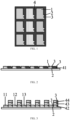
- the present embodiment provides a display substrate including a base substrate 5 and a plurality of pixel regions on the base substrate 5.
- Each of the plurality of pixel regions is provided with a color filter 1 and an auxiliary portion 2 corresponding to the color filter 1.
- the color filter 1 and the auxiliary portion 2 are integrally formed.
- a gas hole 3 is provided in the auxiliary portion 2.
- shape and size of the auxiliary portion 2 are not limited thereto as long as the gas hole 3 is formed inside the auxiliary portion 2, which is not described herein.
- the reason why the laser transfer process is adopted to form the color filter 1 and the auxiliary portion 2 is that the color filter 1 and the auxiliary portion 2 can be formed at a predetermined position using a transfer plate by the laser transfer process, which can avoid overlapping of color filters 1 of various colors.
- the light-shielding pattern 4 is provided between two adjacent pixels to avoid light leakage or light mixing between two adjacent color filters 1.
- the light-shielding pattern 4 includes a black matrix 41.
- a gas hole 3 is provided in the black matrix 41.
- the reason for providing the gas hole 3 in the black matrix 41 is also to allow the generated gas to escape in the process of forming the black matrix 41 by the laser transfer process.
- the light-shielding pattern 4 includes the first portion 42, the second portion 43 and the third portion 44, which are sequentially stacked from bottom to top, and the first portion 42, the second portion 43 and the third portion 44 stacked are provided between the red filter 11, the green filter 12 and the blue filter 13.
- a black matrix-like structure can be formed, so as to block positions between two adjacent color filters and avoid light leakage or light mixing at positions between two adjacent color filters.
- the red filter 11 and the first portion 42 are provided in a same layer and made of a same material, that is, the red filter 11 and the first portion 42 may be formed simultaneously.
- the blue filter 13 and the third portion 44 are provided in a same layer and made of a same material, that is, the blue filter 13 and the third portion 44 may be formed simultaneously, but are in different layers in the macroeconomic sense. Therefore, the first portion 42, the second portion 43 and the third portion 44 are not required to be formed in separate steps, respectively, thereby simplifying fabrication process of the display substrate and improving fabrication efficiency.
- the first portion 42 is integrally formed with the red filter 11 and adjacent to the first portion 42.
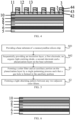
- An insulation layer 6, a first electrode 7, an organic light emitting diode 8, a second electrode 9 and a planarization layer 10 are sequentially provided from bottom to top between the base substrate 5 and the color filter 1.
- the organic light emitting diode 8 is a white organic light emitting diode.
- the reason for this arrangement is that, the red filter 11, the green filter 12 and the blue filter 13 are provided on the planarization layer 10, and thus, the display substrate can operates normally as long as the organic light emitting diode 8 can emit white light.
- an anode, a cathode and a light emitting layer between the anode and the cathode are provided in the organic light emitting diode 8, which is not described here.
- the display substrate of the present embodiment includes the base substrate 5 and the color filter 1 and the auxiliary portion 2 on the base substrate 5, the color filter 1 and the auxiliary portion 2 are integrally formed, and the gas hole 3 is provided in the auxiliary portion 2. Because the color filter 1 and the auxiliary portion 2 are integrally formed, during the formation of the color filter 1 and the auxiliary portion 2, the gas hole 3 provided in the auxiliary portion 2 can allow the gas generated in the process of forming the color filter 1 and the auxiliary portion 2 by a transfer process using a transfer material to escape, thereby forming a more uniform color filter 1 and further improving product yield.
- This embodiment provides a display device including the display substrate.
- the display device may be any product or component with a display function, such as a liquid crystal display panel, an electronic paper, a mobile phone, a tablet computer, a television, a display, a notebook computer, a digital photo frame, a navigator or the like.
- a display function such as a liquid crystal display panel, an electronic paper, a mobile phone, a tablet computer, a television, a display, a notebook computer, a digital photo frame, a navigator or the like.
- the display device of this embodiment includes the display substrate.
- the gas hole provided in the auxiliary portion can allow the gas generated in the process of forming the color filter and the auxiliary portion by a transfer process using a transfer material to escape, thereby forming a more uniform color filter and further improving product yield.
- this embodiment provides a method for fabricating a display substrate, which includes steps S01, S02, S1 and S2.
- an insulation layer 6, a first electrode 7, an organic light emitting diode 8, a second electrode 9 and a planarization layer 10 are sequentially provided on the base substrate 5.
- the organic light emitting diode 8 is white organic light emitting diode.
- step of forming the above structures may be performed by using known techniques and materials, and is not described here.
- Step S1 includes: sequentially providing a color filter material 20, a transfer sacrificial layer 30 and a transfer substrate 40 on the base substrate, hollow-out patterns 401 and bulges 402 being provided at predetermined positions of the transfer substrate 40; irradiating light to corresponding positions of the transfer sacrificial layer 30 via the hollow-out patterns 401 and the bulges 402; melting the transfer sacrificial layer 30 by heat so that the color filter material 20 corresponding to the hollow-out patterns 401 is transferred to predetermined positions on the base substrate to form the color filters and the auxiliary portions, and the bulges 402 allow the gas holes to be formed in the auxiliary portions.
- the transfer substrate 40 is made of a light tight material, and only the hollow-out patterns 401 in the transfer substrate 40 allow light to pass therethrough.
- a position corresponding to each hollow-out pattern 401 is provided with one bulge 402, and the bulge 402 blocks light.
- the color filter material 20 is a red filter material.
- Light (as shown by arrows) is irradiated on the transfer substrate 40 and allowed to pass only at positions corresponding to the hollow-out patterns 401.
- Light is then irradiated onto the transfer sacrificial layer 30, the material of the transfer sacrificial layer 30 is melted by light (or heat), and the red filter material corresponding to the hollow-out patterns 401 is transferred onto the planarization layer 10.
- the material of the transfer sacrificial layer 30 is removed by means of light irradiation, dissolution, or the like, so that the red filters 11 and the auxiliary portions integrally formed with the red filters 11 are formed at the predetermined positions on the planarization layer 10.
- the gas holes will be formed in the auxiliary portions.
- a color filter material 20 which is a green filter material, is provided on the base substrate.
- green filters 12 the auxiliary portions formed integrally with the green filters 12 and the gas holes are formed on the planarization layer 10.
- a color filter material 20 which is a blue filter material, is provided on the base substrate.
- blue filters 13 the auxiliary portions formed integrally with the blue filters 13 and the gas holes are formed on the planarization layer 10.
- a light-shielding pattern is formed between any two adjacent color filters.
- the light-shielding pattern includes a black matrix 41.
- step S2 includes: forming a black matrix 41 by a laser transfer process, and forming gas holes in the black matrix 41.
- the black matrix 41 and the gas holes in the black matrix 41 may be formed using a same method as the color filters, and it is only necessary to change the color filter material 20 to a black matrix material. Detailed description thereof will not be repeated here.
- steps S 1 and S2 are not limited thereto, and may be reversed, which is not described here.
- step S1 includes: sequentially providing the color filter material 20, a photothermal conversion layer 50 and the transfer substrate 40 on the base substrate, hollow-out patterns 401 being provided at predetermined positions of the transfer substrate 40, and bulges 402 being provided on the photothermal conversion layer 50; irradiating light to corresponding positions of the photothermal conversion layer 50 via the hollow-out patterns 401; converting, by the photothermal conversion layer 50, the light into heat, so that the color filter material 20 corresponding to the hollow-out patterns 401 is transferred to predetermined positions on the base substrate to form the color filters and the auxiliary portions, and the bulges 402 allows the gas holes to be formed in the auxiliary portions.
- the color filters include red filters 11, green filters 12 and blue filters 13.
- the light-shielding pattern includes a first portion 42, a second portion 43 and a third portion 44, which are stacked on each other.
- Steps S1 and S2 may be performed at the same time, and include: as shown in FIG. 11 , forming the red filters 11 and the first portions 42 by one laser transfer process, and forming the gas holes in the first portions 42.
- the transfer substrate 40 is made of a light tight material, and only the hollow-out patterns 401 in the transfer substrate 40 allow light to pass therethrough.
- a position corresponding to each hollow-out pattern 401 on the photothermal conversion layer 50 is provided with one bulge 402, and the bulge 402 blocks light.
- the color filter material 20 is a red filter material.
- Light (as shown by arrows) is irradiated on the transfer substrate 40 and allowed to pass only at positions corresponding to the hollow-out patterns 401. Light is then irradiated onto the photothermal conversion layer 50.
- the photothermal conversion layer 50 converts the light into heat, which causes the red filter material corresponding to the hollow-out patterns 401 to be transferred onto the planarization layer 10.
- the red filters 11, the auxiliary portions integrally formed with the red filters 11 and the first portions 42 are formed at the predetermined positions on the planarization layer 10.
- the gas holes will be formed in the auxiliary portions and the first portions 42.
- the first portion 42 is the auxiliary portion 2 that is integrally formed with the red filter 11 and adjacent to the first portion 42.
- the first portion 42 and the red filter 11 are formed simultaneously, the first portion 42 formed adjacent to the red filter 11 may be formed integrally with the red filter 11.
- the first portion 42 is the auxiliary portion 2 connected to the red filter 11, and the gas hole 3 may be formed in the first portion 42, which can simplify fabrication process and improve fabrication efficiency.
- the green filters 12 and the second portions 43 are formed by one laser transfer process, and the gas holes are formed in the second portions 43.
- the color filter material 20 is a green filter material
- the green filters 12, the auxiliary portions integrally formed with the green filters 12, the second portions 43 and the gas holes are formed on the planarization layer 10 through the same steps as above.
- the blue filters 13 and the third portions 44 are formed by one laser transfer process, and the gas holes are formed in the third portions 44.
- the color filter material 20 is a blue filter material
- the blue filters 13, the auxiliary portions integrally formed with the blue filters 13, the third portions 44 and the gas holes are formed on the planarization layer 10 through the same steps as above.
- step S1 includes: sequentially providing the color filter material 20, a photothermal conversion layer 50 and the transfer substrate 40 and a transfer mask plate 60 on the base substrate, the transfer substrate 40 being made of a transparent material, hollow-out patterns 401 being provided at predetermined positions of the transfer mask plate 60, and bulges being provided on the photothermal conversion layer 50; irradiating light to corresponding positions of the photothermal conversion layer 50 via the hollow-out patterns 401 and the transfer substrate 40 corresponding to the hollow-out patterns; converting, by the photothermal conversion layer 50, the light into heat, so that the color filter material 20 corresponding to the hollow-out patterns 401 is transferred to predetermined positions on the base substrate to form the color filters and the auxiliary portions, and the bulges allows the gas holes to be formed in the auxiliary portions.
- the above step S1 differs from the step S1 in previous example in that the transfer substrate 40 is transparent and allows light to pass therethrough, the hollow-out patterns 401 are provided in the transfer mask plate 60 above the transfer substrate 40, and light is irradiated to corresponding positions of the photothermal conversion layer 50 after passing through the hollow-out patterns 401 and the transfer substrate 40 corresponding to the hollow-out patterns 401, so that the color filter material 20 corresponding to the hollow-out patterns 401 is transferred to predetermined positions on the base substrate.
- the gas holes provided in the auxiliary portions can allow the gas generated in the process of forming the color filters and the auxiliary portions by a transfer process using a transfer material to escape, thereby forming more uniform color filters and further improving product yield.
- the display substrate includes the base substrate and the color filters and the auxiliary portions on the base substrate, the color filters and the auxiliary portions are integrally formed, and the gas holes are provided in the auxiliary portions. Because the color filters and the auxiliary portions are integrally formed, during the formation of the color filters and the auxiliary portions, the gas holes provided in the auxiliary portions can allow the gas generated in the process of forming the color filters and the auxiliary portions by a transfer process using a transfer material to escape, thereby forming more uniform color filters and further improving product yield.
Landscapes
- Engineering & Computer Science (AREA)
- Manufacturing & Machinery (AREA)
- Physics & Mathematics (AREA)
- Optics & Photonics (AREA)
- Microelectronics & Electronic Packaging (AREA)
- Electroluminescent Light Sources (AREA)
- Optical Filters (AREA)
- Devices For Indicating Variable Information By Combining Individual Elements (AREA)
Applications Claiming Priority (2)
| Application Number | Priority Date | Filing Date | Title |
|---|---|---|---|
| CN201611207680.XA CN108242454B (zh) | 2016-12-23 | 2016-12-23 | 显示基板及其制备方法、显示装置 |
| PCT/CN2017/101538 WO2018113348A1 (zh) | 2016-12-23 | 2017-09-13 | 显示基板及其制备方法、显示装置 |
Publications (3)
| Publication Number | Publication Date |
|---|---|
| EP3561874A1 EP3561874A1 (en) | 2019-10-30 |
| EP3561874A4 EP3561874A4 (en) | 2020-10-28 |
| EP3561874B1 true EP3561874B1 (en) | 2025-01-08 |
Family
ID=62624386
Family Applications (1)
| Application Number | Title | Priority Date | Filing Date |
|---|---|---|---|
| EP17861210.7A Active EP3561874B1 (en) | 2016-12-23 | 2017-09-13 | Display substrate and manufacturing method thereof, and display device |
Country Status (6)
| Country | Link |
|---|---|
| US (1) | US10804331B2 (enExample) |
| EP (1) | EP3561874B1 (enExample) |
| JP (1) | JP7107837B2 (enExample) |
| KR (1) | KR102206530B1 (enExample) |
| CN (1) | CN108242454B (enExample) |
| WO (1) | WO2018113348A1 (enExample) |
Families Citing this family (6)
| Publication number | Priority date | Publication date | Assignee | Title |
|---|---|---|---|---|
| CN109817164B (zh) * | 2017-11-20 | 2020-10-27 | 上海视涯技术有限公司 | Amoled显示面板和图像显示装置 |
| KR102761175B1 (ko) * | 2019-02-07 | 2025-02-03 | 삼성디스플레이 주식회사 | 색변환 기판 및 표시 장치 |
| CN111403335A (zh) * | 2020-03-26 | 2020-07-10 | 武汉华星光电半导体显示技术有限公司 | 显示器件及其制作方法 |
| CN114578611B (zh) * | 2022-03-15 | 2023-09-05 | 广州华星光电半导体显示技术有限公司 | 彩膜基板、彩膜基板的制作方法以及显示装置 |
| JP2024017711A (ja) * | 2022-07-28 | 2024-02-08 | デクセリアルズ株式会社 | 発光装置の製造方法及び黒色転写フィルム |
| KR20240106343A (ko) * | 2022-12-29 | 2024-07-08 | 엘지디스플레이 주식회사 | 표시 장치 |
Citations (1)
| Publication number | Priority date | Publication date | Assignee | Title |
|---|---|---|---|---|
| JP2010091670A (ja) * | 2008-10-06 | 2010-04-22 | Sumitomo Rubber Ind Ltd | カラーフィルタの製造方法 |
Family Cites Families (23)
| Publication number | Priority date | Publication date | Assignee | Title |
|---|---|---|---|---|
| JPH0493924A (ja) * | 1990-08-07 | 1992-03-26 | Sony Corp | 液晶表示装置 |
| JPH07294716A (ja) * | 1994-04-22 | 1995-11-10 | Matsushita Electric Ind Co Ltd | 液晶表示パネル用カラーフィルター |
| JP3282156B2 (ja) * | 1995-08-07 | 2002-05-13 | 東レ株式会社 | カラーフィルタおよびカラー液晶表示装置 |
| JP2001339055A (ja) * | 2000-05-29 | 2001-12-07 | Asahi Optical Co Ltd | 固体撮像装置のカバー部材と固体撮像装置 |
| WO2002103661A1 (fr) * | 2001-06-19 | 2002-12-27 | International Business Machines Corporation | Unite d'affichage et procede de production de cette unite d'affichage |
| JP4342277B2 (ja) | 2002-12-27 | 2009-10-14 | シャープ株式会社 | カラーフィルタ基板の製造方法、カラーフィルタ基板および表示装置 |
| JP4342342B2 (ja) * | 2003-04-02 | 2009-10-14 | シャープ株式会社 | カラーフィルター、それを用いた表示装置およびそれらの製造方法 |
| KR100667069B1 (ko) * | 2004-10-19 | 2007-01-10 | 삼성에스디아이 주식회사 | 도너 기판 및 그를 사용한 유기전계발광표시장치의 제조방법 |
| KR100742372B1 (ko) * | 2005-11-29 | 2007-07-24 | 삼성에스디아이 주식회사 | 유기전계발광소자의 제조방법 |
| CN101728404B (zh) * | 2008-10-15 | 2011-08-31 | 亚洲光学股份有限公司 | 可逃气的影像感测模块 |
| JP5187276B2 (ja) * | 2009-05-29 | 2013-04-24 | 大日本印刷株式会社 | 半透過型液晶表示装置用カラーフィルタの製造方法 |
| KR101677266B1 (ko) * | 2010-02-12 | 2016-11-18 | 삼성디스플레이 주식회사 | 유기 발광 표시 장치 및 이의 제조 방법 |
| KR101957147B1 (ko) * | 2011-06-01 | 2019-03-12 | 엘지디스플레이 주식회사 | 유기전계 발광소자 및 이의 제조 방법 |
| CN102998841B (zh) * | 2012-12-21 | 2015-07-22 | 京东方科技集团股份有限公司 | 一种显示基板和具有该显示基板的显示装置 |
| KR101957838B1 (ko) * | 2013-05-23 | 2019-03-13 | 엘지디스플레이 주식회사 | 유기발광다이오드 표시장치 및 이의 제조방법 |
| KR102151752B1 (ko) * | 2013-08-05 | 2020-09-04 | 삼성디스플레이 주식회사 | 유기발광 디스플레이 장치 및 그 제조방법 |
| KR102184673B1 (ko) * | 2013-08-14 | 2020-12-01 | 삼성디스플레이 주식회사 | 유기 발광 표시 장치 및 유기 발광 표시 장치의 제조 방법 |
| CN104793357A (zh) * | 2014-01-17 | 2015-07-22 | 鸿富锦精密工业(深圳)有限公司 | 载具、薄膜晶体管阵列基板制造方法及液晶面板制造方法 |
| US9431463B2 (en) | 2014-04-30 | 2016-08-30 | Lg Display Co., Ltd. | Display apparatus |
| KR102151609B1 (ko) | 2014-05-12 | 2020-09-03 | 엘지디스플레이 주식회사 | 디스플레이 장치 및 이의 제조 방법 |
| CN104111564A (zh) * | 2014-07-15 | 2014-10-22 | 京东方科技集团股份有限公司 | 一种显示用基板、显示装置及显示用基板的制作方法 |
| CN104375317B (zh) * | 2014-11-27 | 2017-03-29 | 京东方科技集团股份有限公司 | 一种显示基板、显示装置及彩膜基板的制作方法 |
| CN206322699U (zh) * | 2016-12-23 | 2017-07-11 | 京东方科技集团股份有限公司 | 显示基板、显示装置 |
-
2016
- 2016-12-23 CN CN201611207680.XA patent/CN108242454B/zh active Active
-
2017
- 2017-09-13 EP EP17861210.7A patent/EP3561874B1/en active Active
- 2017-09-13 WO PCT/CN2017/101538 patent/WO2018113348A1/zh not_active Ceased
- 2017-09-13 US US15/771,793 patent/US10804331B2/en active Active
- 2017-09-13 KR KR1020187013034A patent/KR102206530B1/ko active Active
- 2017-09-13 JP JP2018522025A patent/JP7107837B2/ja active Active
Patent Citations (1)
| Publication number | Priority date | Publication date | Assignee | Title |
|---|---|---|---|---|
| JP2010091670A (ja) * | 2008-10-06 | 2010-04-22 | Sumitomo Rubber Ind Ltd | カラーフィルタの製造方法 |
Also Published As
| Publication number | Publication date |
|---|---|
| EP3561874A1 (en) | 2019-10-30 |
| CN108242454A (zh) | 2018-07-03 |
| CN108242454B (zh) | 2020-05-26 |
| KR102206530B1 (ko) | 2021-01-22 |
| JP2020502550A (ja) | 2020-01-23 |
| KR20180088379A (ko) | 2018-08-03 |
| US10804331B2 (en) | 2020-10-13 |
| JP7107837B2 (ja) | 2022-07-27 |
| EP3561874A4 (en) | 2020-10-28 |
| WO2018113348A1 (zh) | 2018-06-28 |
| US20190081109A1 (en) | 2019-03-14 |
Similar Documents
| Publication | Publication Date | Title |
|---|---|---|
| EP3561874B1 (en) | Display substrate and manufacturing method thereof, and display device | |
| CN103794739B (zh) | 有机el 装置的制造方法、有机el 装置、电子设备 | |
| CN216648312U (zh) | 一种显示面板、显示装置 | |
| CN110277508B (zh) | 有机发光二极管显示面板及其制造方法 | |
| US20200295103A1 (en) | Pixel defining structure and fabricating method thereof, display panel and display device | |
| KR20100073356A (ko) | 컬러 전기 영동 표시 장치 및 이의 제조 방법 | |
| CN111785760B (zh) | 一种显示基板及其制备方法、显示装置 | |
| CN110323261A (zh) | 一种显示基板及其制作方法、显示装置 | |
| CN104571716B (zh) | 上基板及制备方法、触控显示面板及制备方法 | |
| WO2020052097A1 (zh) | 阵列基板及显示面板 | |
| CN110993646B (zh) | Oled背板的制备方法及oled背板 | |
| CN110622317B (zh) | 显示基板、制造显示基板的方法和显示设备 | |
| CN206322699U (zh) | 显示基板、显示装置 | |
| WO2014176904A1 (zh) | 显示装置、彩膜基板及其制作方法 | |
| CN102183806A (zh) | 彩色滤光数组及其制造方法 | |
| KR20120107124A (ko) | 컬러 필터 기판의 노광 방법 | |
| CN114400245A (zh) | 一种彩色滤光片、显示面板及彩色滤光片的制备方法 | |
| CN111710699A (zh) | 显示面板及显示面板制作方法 | |
| CN112599552B (zh) | 微发光二极管显示面板及制备方法 | |
| CN110911423B (zh) | 一种基板及其制备方法、掩膜板 | |
| CN101226946B (zh) | 主动阵列基板、液晶显示面板及其制作方法 | |
| CN118678759A (zh) | 显示面板及其制作方法、显示装置 | |
| JP2011017890A (ja) | 電子機器の製造方法 | |
| CN118284168A (zh) | 显示面板、显示装置和显示面板的制备方法 | |
| JP2007279222A (ja) | 表示パネル用基板の製造方法 |
Legal Events
| Date | Code | Title | Description |
|---|---|---|---|
| STAA | Information on the status of an ep patent application or granted ep patent |
Free format text: STATUS: UNKNOWN |
|
| STAA | Information on the status of an ep patent application or granted ep patent |
Free format text: STATUS: THE INTERNATIONAL PUBLICATION HAS BEEN MADE |
|
| PUAI | Public reference made under article 153(3) epc to a published international application that has entered the european phase |
Free format text: ORIGINAL CODE: 0009012 |
|
| STAA | Information on the status of an ep patent application or granted ep patent |
Free format text: STATUS: REQUEST FOR EXAMINATION WAS MADE |
|
| 17P | Request for examination filed |
Effective date: 20180427 |
|
| AK | Designated contracting states |
Kind code of ref document: A1 Designated state(s): AL AT BE BG CH CY CZ DE DK EE ES FI FR GB GR HR HU IE IS IT LI LT LU LV MC MK MT NL NO PL PT RO RS SE SI SK SM TR |
|
| AX | Request for extension of the european patent |
Extension state: BA ME |
|
| DAV | Request for validation of the european patent (deleted) | ||
| DAX | Request for extension of the european patent (deleted) | ||
| R17P | Request for examination filed (corrected) |
Effective date: 20180427 |
|
| A4 | Supplementary search report drawn up and despatched |
Effective date: 20200929 |
|
| RIC1 | Information provided on ipc code assigned before grant |
Ipc: H01L 51/56 20060101ALI20200923BHEP Ipc: H01L 27/32 20060101AFI20200923BHEP |
|
| STAA | Information on the status of an ep patent application or granted ep patent |
Free format text: STATUS: EXAMINATION IS IN PROGRESS |
|
| 17Q | First examination report despatched |
Effective date: 20230216 |
|
| REG | Reference to a national code |
Ref country code: DE Ref legal event code: R079 Free format text: PREVIOUS MAIN CLASS: H01L0027320000 Ipc: H10K0059380000 Ref country code: DE Ref legal event code: R079 Ref document number: 602017087282 Country of ref document: DE Free format text: PREVIOUS MAIN CLASS: H01L0027320000 Ipc: H10K0059380000 |
|
| GRAP | Despatch of communication of intention to grant a patent |
Free format text: ORIGINAL CODE: EPIDOSNIGR1 |
|
| STAA | Information on the status of an ep patent application or granted ep patent |
Free format text: STATUS: GRANT OF PATENT IS INTENDED |
|
| RIC1 | Information provided on ipc code assigned before grant |
Ipc: H10K 50/125 20230101ALN20240711BHEP Ipc: H10K 50/86 20230101ALN20240711BHEP Ipc: H10K 59/38 20230101AFI20240711BHEP |
|
| INTG | Intention to grant announced |
Effective date: 20240813 |
|
| RIC1 | Information provided on ipc code assigned before grant |
Ipc: H10K 50/125 20230101ALN20240806BHEP Ipc: H10K 50/86 20230101ALN20240806BHEP Ipc: H10K 59/38 20230101AFI20240806BHEP |
|
| GRAS | Grant fee paid |
Free format text: ORIGINAL CODE: EPIDOSNIGR3 |
|
| GRAA | (expected) grant |
Free format text: ORIGINAL CODE: 0009210 |
|
| STAA | Information on the status of an ep patent application or granted ep patent |
Free format text: STATUS: THE PATENT HAS BEEN GRANTED |
|
| AK | Designated contracting states |
Kind code of ref document: B1 Designated state(s): AL AT BE BG CH CY CZ DE DK EE ES FI FR GB GR HR HU IE IS IT LI LT LU LV MC MK MT NL NO PL PT RO RS SE SI SK SM TR |
|
| REG | Reference to a national code |
Ref country code: GB Ref legal event code: FG4D |
|
| REG | Reference to a national code |
Ref country code: CH Ref legal event code: EP |
|
| REG | Reference to a national code |
Ref country code: DE Ref legal event code: R096 Ref document number: 602017087282 Country of ref document: DE |
|
| REG | Reference to a national code |
Ref country code: IE Ref legal event code: FG4D |
|
| REG | Reference to a national code |
Ref country code: LT Ref legal event code: MG9D |
|
| REG | Reference to a national code |
Ref country code: NL Ref legal event code: MP Effective date: 20250108 |
|
| REG | Reference to a national code |
Ref country code: AT Ref legal event code: MK05 Ref document number: 1759172 Country of ref document: AT Kind code of ref document: T Effective date: 20250108 |
|
| PG25 | Lapsed in a contracting state [announced via postgrant information from national office to epo] |
Ref country code: NL Free format text: LAPSE BECAUSE OF FAILURE TO SUBMIT A TRANSLATION OF THE DESCRIPTION OR TO PAY THE FEE WITHIN THE PRESCRIBED TIME-LIMIT Effective date: 20250108 |
|
| PG25 | Lapsed in a contracting state [announced via postgrant information from national office to epo] |
Ref country code: RS Free format text: LAPSE BECAUSE OF FAILURE TO SUBMIT A TRANSLATION OF THE DESCRIPTION OR TO PAY THE FEE WITHIN THE PRESCRIBED TIME-LIMIT Effective date: 20250408 |
|
| PG25 | Lapsed in a contracting state [announced via postgrant information from national office to epo] |
Ref country code: FI Free format text: LAPSE BECAUSE OF FAILURE TO SUBMIT A TRANSLATION OF THE DESCRIPTION OR TO PAY THE FEE WITHIN THE PRESCRIBED TIME-LIMIT Effective date: 20250108 |
|
| PG25 | Lapsed in a contracting state [announced via postgrant information from national office to epo] |
Ref country code: PL Free format text: LAPSE BECAUSE OF FAILURE TO SUBMIT A TRANSLATION OF THE DESCRIPTION OR TO PAY THE FEE WITHIN THE PRESCRIBED TIME-LIMIT Effective date: 20250108 |
|
| PG25 | Lapsed in a contracting state [announced via postgrant information from national office to epo] |
Ref country code: ES Free format text: LAPSE BECAUSE OF FAILURE TO SUBMIT A TRANSLATION OF THE DESCRIPTION OR TO PAY THE FEE WITHIN THE PRESCRIBED TIME-LIMIT Effective date: 20250108 |
|
| PG25 | Lapsed in a contracting state [announced via postgrant information from national office to epo] |
Ref country code: IS Free format text: LAPSE BECAUSE OF FAILURE TO SUBMIT A TRANSLATION OF THE DESCRIPTION OR TO PAY THE FEE WITHIN THE PRESCRIBED TIME-LIMIT Effective date: 20250508 Ref country code: NO Free format text: LAPSE BECAUSE OF FAILURE TO SUBMIT A TRANSLATION OF THE DESCRIPTION OR TO PAY THE FEE WITHIN THE PRESCRIBED TIME-LIMIT Effective date: 20250408 |
|
| PG25 | Lapsed in a contracting state [announced via postgrant information from national office to epo] |
Ref country code: HR Free format text: LAPSE BECAUSE OF FAILURE TO SUBMIT A TRANSLATION OF THE DESCRIPTION OR TO PAY THE FEE WITHIN THE PRESCRIBED TIME-LIMIT Effective date: 20250108 |
|
| PG25 | Lapsed in a contracting state [announced via postgrant information from national office to epo] |
Ref country code: LV Free format text: LAPSE BECAUSE OF FAILURE TO SUBMIT A TRANSLATION OF THE DESCRIPTION OR TO PAY THE FEE WITHIN THE PRESCRIBED TIME-LIMIT Effective date: 20250108 Ref country code: PT Free format text: LAPSE BECAUSE OF FAILURE TO SUBMIT A TRANSLATION OF THE DESCRIPTION OR TO PAY THE FEE WITHIN THE PRESCRIBED TIME-LIMIT Effective date: 20250508 |
|
| PG25 | Lapsed in a contracting state [announced via postgrant information from national office to epo] |
Ref country code: GR Free format text: LAPSE BECAUSE OF FAILURE TO SUBMIT A TRANSLATION OF THE DESCRIPTION OR TO PAY THE FEE WITHIN THE PRESCRIBED TIME-LIMIT Effective date: 20250409 Ref country code: BG Free format text: LAPSE BECAUSE OF FAILURE TO SUBMIT A TRANSLATION OF THE DESCRIPTION OR TO PAY THE FEE WITHIN THE PRESCRIBED TIME-LIMIT Effective date: 20250108 |
|
| PG25 | Lapsed in a contracting state [announced via postgrant information from national office to epo] |
Ref country code: AT Free format text: LAPSE BECAUSE OF FAILURE TO SUBMIT A TRANSLATION OF THE DESCRIPTION OR TO PAY THE FEE WITHIN THE PRESCRIBED TIME-LIMIT Effective date: 20250108 |
|
| PG25 | Lapsed in a contracting state [announced via postgrant information from national office to epo] |
Ref country code: SE Free format text: LAPSE BECAUSE OF FAILURE TO SUBMIT A TRANSLATION OF THE DESCRIPTION OR TO PAY THE FEE WITHIN THE PRESCRIBED TIME-LIMIT Effective date: 20250108 |
|
| PG25 | Lapsed in a contracting state [announced via postgrant information from national office to epo] |
Ref country code: SM Free format text: LAPSE BECAUSE OF FAILURE TO SUBMIT A TRANSLATION OF THE DESCRIPTION OR TO PAY THE FEE WITHIN THE PRESCRIBED TIME-LIMIT Effective date: 20250108 |
|
| REG | Reference to a national code |
Ref country code: DE Ref legal event code: R097 Ref document number: 602017087282 Country of ref document: DE |
|
| PG25 | Lapsed in a contracting state [announced via postgrant information from national office to epo] |
Ref country code: DK Free format text: LAPSE BECAUSE OF FAILURE TO SUBMIT A TRANSLATION OF THE DESCRIPTION OR TO PAY THE FEE WITHIN THE PRESCRIBED TIME-LIMIT Effective date: 20250108 |
|
| PGFP | Annual fee paid to national office [announced via postgrant information from national office to epo] |
Ref country code: DE Payment date: 20250919 Year of fee payment: 9 |
|
| PG25 | Lapsed in a contracting state [announced via postgrant information from national office to epo] |
Ref country code: EE Free format text: LAPSE BECAUSE OF FAILURE TO SUBMIT A TRANSLATION OF THE DESCRIPTION OR TO PAY THE FEE WITHIN THE PRESCRIBED TIME-LIMIT Effective date: 20250108 Ref country code: CZ Free format text: LAPSE BECAUSE OF FAILURE TO SUBMIT A TRANSLATION OF THE DESCRIPTION OR TO PAY THE FEE WITHIN THE PRESCRIBED TIME-LIMIT Effective date: 20250108 |
|
| PG25 | Lapsed in a contracting state [announced via postgrant information from national office to epo] |
Ref country code: RO Free format text: LAPSE BECAUSE OF FAILURE TO SUBMIT A TRANSLATION OF THE DESCRIPTION OR TO PAY THE FEE WITHIN THE PRESCRIBED TIME-LIMIT Effective date: 20250108 |
|
| PG25 | Lapsed in a contracting state [announced via postgrant information from national office to epo] |
Ref country code: SK Free format text: LAPSE BECAUSE OF FAILURE TO SUBMIT A TRANSLATION OF THE DESCRIPTION OR TO PAY THE FEE WITHIN THE PRESCRIBED TIME-LIMIT Effective date: 20250108 |
|
| PLBE | No opposition filed within time limit |
Free format text: ORIGINAL CODE: 0009261 |
|
| STAA | Information on the status of an ep patent application or granted ep patent |
Free format text: STATUS: NO OPPOSITION FILED WITHIN TIME LIMIT |